WO2024084635A1 - 画像データ取得方法、画像データ取得装置、端末装置、表示補正システム - Google Patents
画像データ取得方法、画像データ取得装置、端末装置、表示補正システム Download PDFInfo
- Publication number
- WO2024084635A1 WO2024084635A1 PCT/JP2022/038992 JP2022038992W WO2024084635A1 WO 2024084635 A1 WO2024084635 A1 WO 2024084635A1 JP 2022038992 W JP2022038992 W JP 2022038992W WO 2024084635 A1 WO2024084635 A1 WO 2024084635A1
- Authority
- WO
- WIPO (PCT)
- Prior art keywords
- image data
- correction
- luminance
- unit
- display
- Prior art date
- Legal status (The legal status is an assumption and is not a legal conclusion. Google has not performed a legal analysis and makes no representation as to the accuracy of the status listed.)
- Ceased
Links
Images



Classifications
-
- G—PHYSICS
- G09—EDUCATION; CRYPTOGRAPHY; DISPLAY; ADVERTISING; SEALS
- G09G—ARRANGEMENTS OR CIRCUITS FOR CONTROL OF INDICATING DEVICES USING STATIC MEANS TO PRESENT VARIABLE INFORMATION
- G09G3/00—Control arrangements or circuits, of interest only in connection with visual indicators other than cathode-ray tubes
- G09G3/20—Control arrangements or circuits, of interest only in connection with visual indicators other than cathode-ray tubes for presentation of an assembly of a number of characters, e.g. a page, by composing the assembly by combination of individual elements arranged in a matrix no fixed position being assigned to or needed to be assigned to the individual characters or partial characters
-
- G—PHYSICS
- G09—EDUCATION; CRYPTOGRAPHY; DISPLAY; ADVERTISING; SEALS
- G09G—ARRANGEMENTS OR CIRCUITS FOR CONTROL OF INDICATING DEVICES USING STATIC MEANS TO PRESENT VARIABLE INFORMATION
- G09G5/00—Control arrangements or circuits for visual indicators common to cathode-ray tube indicators and other visual indicators
-
- G—PHYSICS
- G09—EDUCATION; CRYPTOGRAPHY; DISPLAY; ADVERTISING; SEALS
- G09G—ARRANGEMENTS OR CIRCUITS FOR CONTROL OF INDICATING DEVICES USING STATIC MEANS TO PRESENT VARIABLE INFORMATION
- G09G5/00—Control arrangements or circuits for visual indicators common to cathode-ray tube indicators and other visual indicators
- G09G5/02—Control arrangements or circuits for visual indicators common to cathode-ray tube indicators and other visual indicators characterised by the way in which colour is displayed
-
- G—PHYSICS
- G09—EDUCATION; CRYPTOGRAPHY; DISPLAY; ADVERTISING; SEALS
- G09G—ARRANGEMENTS OR CIRCUITS FOR CONTROL OF INDICATING DEVICES USING STATIC MEANS TO PRESENT VARIABLE INFORMATION
- G09G5/00—Control arrangements or circuits for visual indicators common to cathode-ray tube indicators and other visual indicators
- G09G5/10—Intensity circuits
Definitions
- This disclosure relates to an image data acquisition method, an image data acquisition device, a terminal device, and a display correction system for acquiring image data for creating luminance correction data.
- the in-plane brightness unevenness of display panels such as liquid crystal panels and self-luminous panels (such as organic EL (Electroluminescence) panels) has been reduced by Demura (removal of in-plane display unevenness) processing at the time of shipment from the factory.
- Demura Removal of in-plane display unevenness
- the output image displayed on the display panel is photographed by a photographing device, and the photographed output image data is used to reduce the in-plane brightness unevenness of the display panel.
- the output image data used to reduce the in-plane luminance unevenness of the display panel is data captured by a capture device, and so depending on the in-plane distribution of detected luminance within the capture range of the capture device (unevenness caused by the capture system), it may not be possible to appropriately reduce the in-plane luminance unevenness of the display panel.
- a capture device is used that is small enough that the in-plane distribution of detected luminance within the capture range can be ignored, or if the in-plane distribution of detected luminance within the capture range is automatically adjusted, it may be possible to appropriately reduce the in-plane luminance unevenness of the display panel even with output image data obtained by capture; however, such capture devices are high performance and expensive.
- the present disclosure has been made to solve the above problems, and aims to provide an image data acquisition method, image data acquisition device, terminal device, and display correction system that can reduce in-plane luminance unevenness of a display panel by an inexpensive method that takes into account the in-plane distribution of detected luminance in the shooting range of the shooting device, not only at the time of factory shipment but also over time.
- the image data acquisition method is a method for acquiring image data for creating correction data for performing luminance correction or chromaticity correction on a display screen of a display device, and includes a first step of instructing a user to capture an image of the display screen to be corrected within the shooting range of a shooting device used by the user, and further instructing the user to capture multiple images of the display screen moved to other positions within the shooting range of the shooting device, and a second step of acquiring the multiple pieces of shooting data captured by the user based on the instructions issued in the first step as image data.
- An image data acquisition device is an image data acquisition device that acquires image data for creating luminance correction data for performing luminance correction or chromaticity correction on a display screen of a display device, and includes an image capture instruction unit that instructs a user to capture an image of the display screen to be corrected within the capture range of an image capture device used by the user, and further instructs the user to capture multiple images of the display screen moved to other positions within the capture range of the image capture device, and an image capture data acquisition unit that acquires the multiple image capture data captured by the user based on the instructions of the image capture instruction unit as image data.
- the present disclosure makes it possible to reduce in-plane luminance unevenness of a display panel using an inexpensive method that takes into account the in-plane distribution of detected luminance in the shooting range of the imaging device.
- FIG. 1 is a schematic configuration block diagram of a smartphone according to a first embodiment of the present disclosure.
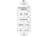
- 10 is a flowchart showing a process flow when a luminance correction processing application is executed by an application execution unit in the smartphone shown in FIG. 1 .
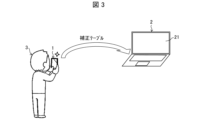
- FIG. 13 is a diagram showing an image in which a user is using a smartphone to capture an image of a display panel of a display device.
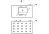
- 2 is a diagram for explaining a method of acquiring image data by a camera provided in the smartphone shown in FIG. 1.
- 5 is a diagram showing an example of image data captured by the image acquisition method shown in FIG. 4.
- 2A to 2C are diagrams illustrating a method for removing external light reflection (glare) contained in image data captured by the camera of the smartphone shown in FIG. 1 .
- 10A and 10B are diagrams illustrating a method for dealing with a change in the display panel position in image data captured by a camera included in the smartphone shown in FIG. 1 .
- 10A and 10B are diagrams illustrating another method for dealing with the variation in the display panel position in image data captured by the camera of the smartphone shown in FIG. 1 .
- a correction table for correcting uneven luminance on a display screen of a display device is created by a terminal device used by a user, for example, a mobile terminal such as a smartphone or a tablet terminal.
- the smartphone 1 is a schematic block diagram of a smartphone (imaging device) 1.
- the smartphone 1 includes a control unit 10, a touch panel 11, an imaging unit 12, a storage unit 13, and a communication unit (transmission unit) 14.
- the control unit 10 controls each unit included in the smartphone 1.
- the control unit 10 will be described in detail later.
- the touch panel 11 is an input and display panel formed by superimposing an input unit 111 that accepts touch input from the user and a display unit 112 that displays images.
- the display unit 112 is composed of, for example, an organic EL panel or a liquid crystal panel, and displays various information using images, text, etc.
- the input unit 111 functions as an operation unit that accepts touch input to perform various operations on the smartphone 1 based on the information displayed on the display unit 112.
- the photographing unit 12 is equipped with an imaging element (not shown).
- the imaging element may be a CCD (Charge Coupled Device) sensor, a CMOS (Complementary Metal Oxide Semiconductor) sensor, or the like.
- the storage unit 13 is a storage device that stores various data used by the smartphone 1.
- the storage unit 13 stores brightness correction data, correction tables, etc., generated by the brightness correction application image capture device executed by the control unit 10.
- the communication unit 14 is capable of communicating with a display device having a display panel to be corrected, and transmits data (such as a correction table) necessary for correcting the brightness of the display panel. If the display device is located near the smartphone 1, communication between the communication unit 14 and the display device uses short-range communication such as Bluetooth (registered trademark) communication or infrared communication. Communication between the communication unit 14 and the display device may also be performed via the Internet. For example, the communication unit 14 transmits data (such as a correction table) necessary for correcting the brightness of the display panel to a cloud via the Internet, and the display device receives the data necessary for correcting the brightness of the display panel from the cloud as necessary.
- data such as a correction table
- the control unit 10 includes a touch acquisition unit 101, a display control unit 102, a shooting control unit 103, a communication control unit 104, and an application execution unit (image data acquisition device) 105.
- the touch acquisition unit 101 acquires an electrical signal indicating a touch from the input unit 111, and calculates the touch coordinates of the touch.
- touch coordinates refers to the touch coordinates (coordinates at the detection resolution of the touch panel) on the input surface of the input unit 111 converted into values indicating which vertical and horizontal pixels were touched on the coordinate display surface of the display surface of the display unit 112.
- the touch acquisition unit 101 supplies the calculated touch coordinates to the application execution unit 105.
- the touch acquisition unit 101 can also hold the touch coordinates in chronological order. Then, it supplies touch information as the trajectory of touch operations (such as a drag operation or a long press operation) that have been continuously input over a certain period of time to the application execution unit 105.
- the display control unit 102 controls the display of the display unit 112. For example, the display control unit 102 generates a screen in response to an instruction from the application execution unit 105 and displays it on the display unit 112.
- the imaging control unit 103 controls the imaging of the imaging unit (camera) 12.
- the imaging control unit 103 controls the imaging of the imaging unit 12 based on instructions from the application execution unit 105.
- the imaging data captured by the imaging unit 12 is supplied to the application execution unit 105 via the imaging control unit 103. Note that in this disclosure, the imaging data captured by the imaging unit 12 will be described as image data.
- the communication control unit 104 controls the communication of the communication unit 14.
- the communication control unit 104 transmits data for brightness correction (such as a correction table) generated by the application execution unit 105 of the smartphone 1 to a display device having a display panel to be corrected.
- data is transmitted to the display device by performing communication via Bluetooth (registered trademark), for example.
- the application execution unit 105 executes various applications on the smartphone 1. Specifically, the application execution unit 105 executes processing in response to various pieces of information supplied from the touch acquisition unit 101, the communication control unit 104, etc.
- the application execution unit 105 includes a shooting instruction unit 51, a shooting data acquisition unit 52, a detected brightness correction unit 53, a brightness correction data creation unit 54, and a correction table creation unit 55.
- the shooting instruction unit 51 instructs the user operating the smartphone 1 to shoot using the shooting unit 12. Specifically, in order to instruct the user to shoot using the shooting unit 12, the shooting instruction unit 51 causes the display unit 112 of the touch panel 11 of the smartphone 1 to display an image prompting the user to shoot. Note that while it is preferable to display an image on the display unit 112 to instruct the user to shoot, it is also possible to output audio prompting the user to shoot from a speaker (not shown) of the smartphone 1. Note that the details of the shooting instructions given by the shooting instruction unit 51 will be described later.
- the shooting data acquisition unit 52 acquires the shooting data captured by the shooting unit 12 in response to shooting instructions from the shooting instruction unit 51 as image data, and sends the acquired image data to the detection brightness correction unit 53. There are no particular limitations on the timing at which the shooting data acquisition unit 52 sends image data to the detection brightness correction unit 53. For example, the shooting data acquisition unit 52 may send image data to the detection brightness correction unit 53 each time it acquires it, or may acquire a predetermined number of image data and then send them all together to the detection brightness correction unit 53.
- the detected brightness correction unit 53 calculates the in-plane distribution of detected brightness within the shooting range of the shooting unit 12 from the multiple image data acquired by the shooting data acquisition unit 52.
- the detected brightness correction unit 53 then corrects the in-plane distribution of detected brightness for one of the multiple image data acquired by the shooting data acquisition unit 52 using at least the calculated in-plane distribution of detected brightness.
- the brightness-corrected image data is sent to the brightness correction data creation unit 54.
- the "in-plane distribution of detected brightness” refers to imaging unevenness caused by the shooting unit 12, etc., contained in the image data (brightness data) detected by the shooting unit 12, and indicates the distribution of brightness components. In other words, it is unevenness caused by the shooting system that is unrelated to the subject being shot (brightness unevenness of the display panel 21 of this disclosure).
- the detection brightness correction unit 53, the brightness correction data creation unit 54, and the correction table creation unit 55 constitute a correction data creation unit that creates correction data for performing brightness correction on the display screen to be corrected (for example, the display panel 21 of the display device 2 shown in FIG. 3) using the image data acquired by the shooting data acquisition unit 52.
- the correction data includes the brightness correction data created by the brightness correction data creation unit 54 and the correction table created by the correction table creation unit 55.
- the correction data is created as follows.
- the luminance correction data creation unit 54 analyzes the luminance components of the image data that has been subjected to detection luminance correction and is sent from the detection luminance correction unit 53, and creates luminance correction data.
- luminance components refer to specific numerical values of the luminance at each position of the image data. Details of the creation of luminance correction data by the luminance correction data creation unit 54 will be described later.
- the correction table creation unit 55 creates a correction table for performing luminance correction on the display screen to be corrected, from the luminance correction data created by the luminance correction data creation unit 54. By using this correction table, it is possible to perform luminance correction at any color/gradation by applying interpolation processing to the image data to be corrected.
- the created correction table is stored in the memory unit 13, and is also sent from the communication unit 14 via the communication control unit 104 to the display device equipped with the display panel to be corrected, and is saved in the non-volatile memory within the display device. As a result, the display device can display an image with an appropriate luminance distribution by reflecting the correction table saved in the non-volatile memory on the image to be displayed.
- Fig. 2 is a flowchart showing a process flow when a brightness correction process application is executed by the application execution unit 105 in the smartphone 1.
- Fig. 3 is a diagram showing an image in which a user 3 uses the smartphone 1 to photograph the display panel 21 of the display device 2.
- Fig. 4 is a diagram for explaining a method of photographing a plurality of images of the display panel 21 of the display device 2, which is the subject of the photographing.
- Fig. 5 is a diagram showing an example of an image photographed by the photographing method shown in Fig. 4.
- the photographing instruction unit 51 instructs the user 3 to photograph the display panel 21 to be corrected (step S1: first step). Specifically, the photographing instruction unit 51 instructs the user 3, for example, to photograph an image of the display panel (display screen) 21 of the display device 2 to be corrected within the photographing range of the photographing unit 12 of the smartphone 1 used by the user 3, and further instructs the user 3 to photograph multiple images of the display panel 21 moved to another position within the photographing range of the photographing unit 12.
- a video prompting the user to take a photograph may be displayed on the display unit 112 of the touch panel 11 of the smartphone 1, or a sound prompting the user to take a photograph may be output from the speaker (not shown) of the smartphone 1.
- the user 3 photographs the display panel 21 of the display device 2, which is the object of correction, with the photographing unit 12, which is the camera of the smartphone 1, according to a photographing instruction from the smartphone 1 that the user 3 operates.
- the photographing unit 12 which is the camera of the smartphone 1
- multiple images of the display panel 21, which is the object of correction are photographed so that the position of the display panel 21 to be corrected in the photographing area 12a of the photographing unit 12 changes.
- photographing multiple images for example, as shown by reference numeral 1041 in FIG.
- the position of the display panel 21 is changed and photographing is repeated so that the circle mark 21a located approximately at the center of the display panel 21 of the display device 2 within the photographing area 12a of the photographing unit 12 of the smartphone 1 is distributed within the photographing area 12a as shown by reference numeral 1042 in FIG.
- the smartphone 1 provides guidance to the user 3 by a message for the user, etc., to photograph so that the display panel 21 is in the center, the display panel 21 is in the upper left corner, the display panel 21 is in the lower right corner, the display panel 21 is in the upper right corner, ...
- a photograph of the image on the display panel 21 shown by reference numerals 1051, 1052, 1053, 1054, ... in FIG. 5 is obtained. Note that as long as the user 3 can take a photograph as described above by using user guidance or the like, the circle 21a does not necessarily need to be displayed on the screen.
- the positions of the points corresponding to the circles 21a within the photographing area 12a do not have to be specifically determined positions, but it is preferable that they are positions that are widely and evenly distributed within the photographing area 12a.
- the analysis here is an analysis of the in-plane distribution of the detected brightness of the image capture unit 12 of the smartphone 1, which is performed in step S3 below.
- the photographing data acquisition unit 52 acquires the photographed data taken in step S1 as a photograph (image data) (step S2: second step).
- the photographing data acquisition unit 52 sends the acquired image data to the detection brightness correction unit 53.
- the photographing data acquisition unit 52 acquires 20 types of image data and sends them to the detection brightness correction unit 53 each time.
- the detection brightness correction unit 53 calculates the in-plane distribution of the detection brightness within the shooting range of the shooting unit 12 from the 20 types of image data from the shooting data acquisition unit 52, and corrects the in-plane distribution of the detection brightness for one of the 20 types of image data from the shooting data acquisition unit 52 using at least the calculated in-plane distribution of the detection brightness (step S3: corresponding to the detection brightness correction step of the third step). Specifically, the detection brightness correction unit 53 first calculates the in-plane distribution of the detection brightness of the shooting unit 12 from the difference in the detection brightness of each of the 20 pieces of image data.
- the detection brightness of a specific location (for example, the position of the circle 21a in the center of the panel) of the display panel 21 to be corrected in the image data is compared between the 20 pieces of image data to analyze the in-plane distribution of the detection brightness in the shooting unit 12 of the smartphone 1. If a difference occurs in the detection value of the brightness as a result of this analysis, it is considered that this is due to the in-plane detection brightness dependency of the shooting unit 12 of the smartphone 1. In other words, in the 20 captured image data, the luminance at the same location would normally be the same, so there would be no difference in the detected luminance values. However, the fact that a difference occurred in the detected luminance values means that the detected luminance of the image capture unit 12 of the smartphone 1 itself has in-plane dependence.
- the detected luminance correction unit 53 then sends the image data in which the in-plane distribution of the detected luminance has been corrected to the luminance correction data creation unit 54.
- the luminance correction data creation unit 54 analyzes the luminance components of the image data in which the in-plane distribution of the detected luminance has been corrected by the detected luminance correction unit 53, and creates luminance correction data (step S4: corresponds to the third step of creating luminance correction data). Specifically, the luminance correction data creation unit 54 analyzes the luminance components of the image data in which the in-plane distribution of the detected luminance has been corrected, and creates luminance correction data that corrects the luminance unevenness of the display panel 21 from the analysis results.
- the correction table creation unit 55 creates a correction table from the luminance correction data created by the luminance correction data creation unit 54 (step S5: corresponding to the third step of creating a correction table).
- an interpolation process or the like is added from the luminance correction data for each color and each gradation to create a correction table for performing luminance correction on the display panel 21 so that luminance correction can be performed for any color/gradation.
- the created correction table is stored in the memory unit 13 in the smartphone 1, and is also sent to the display device 2 via the communication unit 14 and stored in the built-in non-volatile memory (not shown).
- the smartphone 1 configured as described above processes multiple pieces of image data obtained by taking multiple images of the display panel 21 to be corrected from different locations, removes the luminance unevenness caused by the image capture unit 12, and creates image data of the display panel 21 to be corrected.
- the luminance components of the image data from which the luminance unevenness caused by the image capture unit 12 has been removed are then further analyzed, a correction table for correcting the luminance unevenness of the display panel 21 is created and stored in the non-volatile memory within the display panel 21, and the correction table is used on the TCON side of the display device 2 to realize an image display that reflects the image correction.
- the gradation of each pixel of the display panel 21 corresponds to the luminance in the image data.
- the gradation of each of the red subpixels, green subpixels, and blue subpixels of the display panel 21 may be analyzed, and luminance may be corrected by correcting the gradation.
- This correction also makes it possible to correct the luminance unevenness of the display panel 21 described above.
- correction of the luminance of each pixel of the display panel 21 includes correction performed through analysis and correction of the gradation of each pixel of the display panel 21.
- the display panel 21 of the display device 2 reflects external light (glares), and the external light reflection may affect the brightness unevenness of the display panel 21. For this reason, when Demura processing is performed on the display panel 21 of the display device 2, it is preferable to perform the image capture in a dark room where there is no external light reflection.
- the following embodiment 2 an example of eliminating the effects of external light reflection when Demura processing is performed on the display panel 21 of the display device 2 in a bright room is described.
- FIG. 6 is a diagram showing an example of a photograph of an image of the display panel 21 taken when removing the effect of external light reflection (glare) on the display panel 21 when correcting uneven brightness on the display panel 21 of the display device 2.
- the display panel 21, which is the panel to be corrected is set to black display (V0 display) and the image is captured by the image capture unit 12 of the smartphone 1.
- V0 display black display
- the black display is approximately 0 nits, only the effects of external light reflection (glare) should appear within the panel area to be corrected in the image data.
- the detection luminance correction unit 53 and the luminance correction data creation unit 54 in the application execution unit 105 of the smartphone 1 described in the first embodiment create luminance correction data that takes into account external light reflection.
- the detection luminance correction unit 53 first analyzes the external light reflection component from at least one of the multiple pieces of image data acquired by the shooting data acquisition unit 52.
- the detection luminance correction unit 53 subtracts the detection luminance corresponding to the external light reflection component from the detection luminance of the image data in which the external light reflection component has been analyzed, and then corrects the in-plane distribution of the detection luminance for the image data from which the detection luminance corresponding to the external light reflection component has been subtracted.
- the luminance correction data creation unit 54 analyzes the luminance component of the image data whose detection luminance has been corrected by the detection luminance correction unit 53 taking into account the external light reflection component, and creates luminance correction data.
- the external light reflection may differ depending on the angle at which the panel is photographed
- multiple images are taken so that the position of the display panel 21, which is the panel to be corrected, changes in the photographing area 12a of the photographing unit 12 of the smartphone 1, as in the case of creating the brightness correction data in the first embodiment.
- the display panel 21 of the display device 2 is displayed in black, and multiple images of the display panel 21 are photographed so that the external light reflection area 21b changes in the photographing area 12a of the photographing unit 12.
- the smartphone 1 provides guidance to the user 3 by using a message for the user to photograph the display panel 21 so that the display panel 21 is in the center, the upper left corner, the lower right corner, the upper right corner, etc.
- a message for the user to photograph the display panel 21 so that the display panel 21 is in the center, the upper left corner, the lower right corner, the upper right corner, etc.
- the image of the display panel 21 shown by reference numerals 1061, 1062, 1063, 1064, etc. in FIG. 6 is obtained.
- (Response to panel position fluctuations (1)) 7 is a diagram for explaining how to deal with panel position variations in image data.
- the display screen of the display panel 21 to be corrected which is shown in the image data, is converted into an image with a number of pixels that the actual display panel 21 can display. This conversion is performed by the luminance correction data creation unit 54 described in the first embodiment.
- the luminance correction data creation unit 54 associates the position in the display screen of the display panel 21 to be corrected, which is included in the image data subjected to the detection luminance correction by the detection luminance correction unit 53, with the position in the display screen of the actual display panel 21 to be corrected, converts the display data of the display screen to be corrected, which is included in the image data, into display data to be displayed on the display screen of the actual display device, analyzes the luminance components in the converted display data, and creates luminance correction data for performing luminance correction on the display screen on which the display data is displayed, based on the analysis result.
- the luminance correction data creation unit 54 first detects the four corners (four circles 22 in the figure) of the display panel 21 of the display device 2 displayed in the shooting area 12a from the image data shown by reference numeral 1071 in FIG. 7, and identifies the coordinates within the shooting area 12a. Furthermore, the luminance correction data creation unit 54 determines a coordinate conversion formula for converting from the identified coordinates within the shooting area 12a to the actual position (pixel coordinates) within the display panel 21 for any location (for example, two circles 21c) within the display area of the display panel 21 within the shooting area 12a.
- a conversion is performed from the coordinates in the shooting area 12a to the actual position (pixel coordinates) in the display panel 21.
- This conversion is performed, for example, by the brightness correction data creation unit 54 converting the coordinates in the shooting area 12a based on the coordinate conversion formula determined in the previous process.
- the brightness correction data creation unit 54 extracts the display area of the display panel 21 from within the shooting area 12a of the shooting unit 12, and converts it into an image (display data) with a number of pixels that can actually be displayed on the display panel 21, as shown by reference numeral 1072 in FIG. 7.
- the brightness components of this converted display data are analyzed, and from the analysis results, brightness correction data is created for performing brightness correction on the display screen on which the display data is being displayed.
- the correction table creation unit 55 creates a correction table for performing luminance correction on the display screen from the luminance correction data created by the luminance correction data creation unit 54.
- the correction table created by the correction table creation unit 55 is sent to the display device 2 having the display panel 21, stored in a non-volatile memory, and used for luminance correction of the display data as necessary.
- Fig. 8 is a diagram for explaining how to deal with panel position fluctuations in image data.
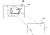
- the positions of the four corners (four circles 22 in the figure) of the display panel 21 in the shooting area 12a are detected and used as a reference for coordinate conversion, but as shown by reference numeral 1081 in Fig. 8, a solid image including four points 21d serving as markers is displayed on the display screen of the display panel 21 in the shooting area 12a, and the positions of the four points 21d serving as markers are used as a reference for coordinate conversion.
- a solid image including four dots 21d serving as markers is displayed on the display screen of the display panel 21 of the display device 2 displayed in the shooting area 12a, and is photographed by the shooting unit 12 of the smartphone 1.
- brightness unevenness caused by the shooting unit 12 of the smartphone 1 is removed.
- Coordinate conversion of the display panel 21 contained in the image data obtained in this manner is performed. This conversion is also performed by the brightness correction data creation unit 54 described in the first embodiment.
- the luminance correction data creation unit 54 first detects four points 21d that serve as markers in the display panel 21 of the display device 2 displayed in the shooting area 12a from the image data shown by reference numeral 1081 in FIG. 8, and identifies their coordinates in the shooting area 12a. Furthermore, the luminance correction data creation unit 54 determines a coordinate conversion formula for converting from the identified coordinates in the shooting area 12a to positions (pixel coordinates) in the actual display panel 21 for any points (e.g., two circles 21c) in the display area of the display panel 21 in the shooting area 12a.
- a conversion is performed from the coordinates in the shooting area 12a to the actual position (pixel coordinates) in the display panel 21.
- This conversion is performed, for example, by the brightness correction data creation unit 54 converting the coordinates in the shooting area 12a based on the coordinate conversion formula determined in the previous process.
- the brightness correction data creation unit 54 extracts the display area of the display panel 21 from within the shooting area 12a of the shooting unit 12, and converts it into an image (display data) with a number of pixels that can actually be displayed on the display panel 21, as shown by reference numeral 1082 in FIG. 8.
- the brightness components of this converted display data are analyzed, and brightness correction data is created from the analysis results for performing brightness correction on the display screen on which the display data is being displayed.
- the correction table creation unit 55 creates a correction table for performing luminance correction on the display screen from the luminance correction data created by the luminance correction data creation unit 54.
- the correction table created by the correction table creation unit 55 is sent to the display device 2 having the display panel 21, stored in a non-volatile memory, and used for luminance correction of the display data as necessary.
- the size and color of the marker points 21d can be adjusted for convenience of detection, so coordinate conversion can be performed more accurately than by detecting the four corners of the display panel 21 shown by reference numeral 1071 in FIG. 7.
- the marker point 21d on the display screen of the display panel 21 is not necessary for actual correction, but by complementing the original luminance of the location of the marker point 21d from the luminance distribution around the marker, it is possible to correct the location of the marker point 21d with a certain degree of accuracy. To perform correction with greater accuracy, it is preferable that the marker point 21d is small.
- the smartphone 1 and the display device 2 constitute a display correction system that corrects the brightness unevenness of the display panel 21 of the display device 2.
- the smartphone 1 performs the process up to the creation of correction data for correcting the in-plane unevenness of the actual display panel 21, but this is not limited to this.
- the processing up to the shooting instruction unit 51 and the shooting data acquisition unit 52 of the application execution unit 105 in the smartphone 1 may be performed on the smartphone 1 side, and the processing of the detection brightness correction unit 53, the brightness correction data creation unit 54, and the correction table creation unit 55 may be performed on the display device 2 side.
- the processing of the detection brightness correction unit 53, the brightness correction data creation unit 54, and the correction table creation unit 55 may be performed on a third device (including on the cloud) other than the smartphone 1 and the display device 2.
- a third device including on the cloud
- the correction table is ultimately stored in a non-volatile memory in the terminal to be corrected.
- a black screen (V0 solid screen) is displayed on the display panel 21 to be corrected, and while the smartphone 1 body and the display panel 21 to be corrected are kept approximately parallel, multiple images are captured so that the position of the display panel 21 changes within the imaging unit 12 of the smartphone 1.
- the image data captured here may be one piece, but it is preferable to capture two or more pieces.
- the display screen of the display panel 21 is changed to a solid screen of, for example, (red, green, blue, white) x (0 gradation, 32 gradation, 64 gradation, 96 gradation, 128 gradation, 160 gradation, 192 gradation, 224 gradation, 255 gradation), and the following processes (1) to (6) are repeated.
- the display panel 21 to be corrected is photographed (obtaining image data to be used for correction).
- image data is acquired to obtain correction data for the in-plane dependency of the luminance detected by the imaging unit 12.
- the process (1) does not have to be performed for each display color and gradation in order to shorten the processing time. If a certain correction effect is obtained, it may be performed only for a specific color and specific gradation, and then applied to all colors and gradations.
- This corrected image data is an image in which the in-plane dependency of the detected brightness by the image capture unit 12 is eliminated. Furthermore, if external light reflection is confirmed in the photograph in (2) and the external light reflection is removed from the image data, the image data obtained in (4) is an image in which the in-plane dependency of the detected brightness by the image capture unit 12 is eliminated and the external light reflection is removed.
- the image data obtained in (4) is analyzed, and the position (pixel coordinates) in the image data of the display panel 21 to be corrected in the smartphone 1 is matched with the position (pixel coordinates) in the display panel 21 to be actually corrected, and the data of the image data in (4) at the location on the display panel 21 is converted into data for the actual display panel 21.
- the data for the display panel 21 in (6) and (5) can be considered in-plane unevenness data for the display panel 21 for each color and gradation, so the luminance components are analyzed and converted into luminance correction data.
- a correction table is created by interpolation processing or the like that enables brightness correction for any color/gradation, and the correction table is stored in the non-volatile memory in the display panel 21 of the display device 2.
- the display device 2 can display an image with appropriate brightness by applying the above-mentioned correction table stored in the non-volatile memory to the image signal to be displayed on the display panel 21.
- the series of processes (1) to (6) above uses solid screens with 0, 32, 64, 96, 128, 160, 192, 224, and 255 gradations for the four colors red, green, blue, and white.
- corrections can be made according to the gradation and color.
- correction data that eliminates in-plane unevenness can be created for each gradation and color. Note that for corrections related to the gradations between the gradations shown above, such as 16 gradations, the in-plane unevenness can be eliminated by interpolation processing.
- the correction table may be stored in a non-volatile memory and used for luminance correction. Therefore, in the present disclosure, even if the display surface of the display panel 21 is a screen other than a solid screen, it is possible to appropriately correct the luminance unevenness of the display panel 21.
- the image data acquisition method of the present disclosure has been described as being applied to the acquisition of image data for performing luminance correction on the display screen of a display device. However, if this luminance correction is performed simultaneously for each of the tristimulus values X, Y, and Z in the XYZ color system, chromaticity correction can also be achieved.
- Smartphone terminal device, photographing device
- User 10 Control unit 11 Touch panel 12
- Shooting unit 12a Shooting area 13
- Storage unit 14 Communication unit (transmission unit) 21 display panel 21a, 21c, 21d, 22 circle 21b external light reflection area 51 shooting instruction unit 52 shooting data acquisition unit 53 detection brightness correction unit (correction data creation unit) 54 Brightness correction data creation unit (correction data creation unit) 55
Landscapes
- Engineering & Computer Science (AREA)
- Physics & Mathematics (AREA)
- Computer Hardware Design (AREA)
- General Physics & Mathematics (AREA)
- Theoretical Computer Science (AREA)
- Controls And Circuits For Display Device (AREA)
Abstract
工場出荷時はもとより、経年時であっても、安価な方法で、且つ、撮影装置の撮影範囲における検出輝度の面内分布を考慮した表示パネルの面内輝度ムラの軽減を行うことができる画像データ取得方法、画像データ取得装置、端末装置および表示補正システムを提供することを目的とする。 本開示の画像データ取得方法は、ユーザに対して、撮影装置の撮影部の撮影範囲内で、補正対象である表示パネルの像を撮影するよう指示を出し、さらに、撮影部の撮影範囲内の他の位置に表示パネルの像を移動させた像を複数撮影するように指示を出す第1ステップ(S1)と、ユーザによって撮影された複数の撮影データを画像データとして取得する第2ステップ(S2)と、を含む。
Description
本開示は、輝度補正データを作成するための画像データを取得する画像データ取得方法、画像データ取得装置、端末装置、表示補正システムに関する。
従来、液晶パネルや自発光パネル(例えば有機EL(Electro luminescence)パネル等)の表示パネルの面内輝度ムラは、工場出荷時に、Demura(パネル面内表示ムラ除去)処理によって軽減させていた。例えば特許文献1では、表示パネルにおいて表示された出力画像を撮影装置によって撮影し、撮影した出力画像データを用いて、表示パネルの面内輝度ムラを軽減させている。
しかしながら、上述のような従来技術では、表示パネルの面内輝度ムラを軽減するために用いる出力画像データが、撮影装置によって撮影されたデータであるため、撮影装置の撮影範囲内における検出輝度の面内分布(撮影系起因のムラ)によっては、表示パネルの面内輝度ムラを適切に軽減できない場合がある。なお、撮影範囲における検出輝度の面内分布が十分に無視できるほど小さな撮影装置を用いれば、あるいは撮影範囲における検出輝度の面内分布を自動調整すれば、撮影によって得られた出力画像データであっても、表示パネルの面内輝度ムラを適切に軽減することができるが、このような撮影装置は高性能であり高価である。
また、工場出荷時に、Demura処理を施し、表示パネルの面内輝度ムラを軽減させても、経年により、表示パネルの面内輝度ムラが再び生じうる。このような場合、再び、特許文献1に記載された技術を用いても、上述したように、表示パネルの面内輝度ムラを適切に軽減できない場合がある。一方で、表示パネルの面内輝度ムラを適切に軽減するための撮影装置は高価かつ設置場所・設置方法等に制約が生じるため、経年での対応に何度も利用するのが現実的ではない(ハードルが高い)という問題が生じる。
本開示は、上記の課題を解決するためになされたものであり、工場出荷時はもとより、経年時であっても、安価な方法で、且つ、撮影装置の撮影範囲における検出輝度の面内分布を考慮した表示パネルの面内輝度ムラの軽減を行うことができる画像データ取得方法、画像データ取得装置、端末装置および表示補正システムを提供することを目的とする。
本開示の一態様にかかる画像データ取得方法は、表示装置の表示画面の輝度補正または色度補正を行うための補正データを作成するための画像データの取得方法であって、ユーザに対して、当該ユーザが使用する撮影装置の撮影範囲内で、補正対象である前記表示画面の像を撮影するよう指示を出し、さらに、撮影装置の撮影範囲内の他の位置に移動させた前記表示画面の像を複数撮影するように指示を出す第1ステップと、前記第1ステップにおいて出された指示に基づいて前記ユーザによって撮影された複数の撮影データを画像データとして取得する第2ステップと、を含む。
本開示の一態様にかかる画像データ取得装置は、表示装置の表示画面の輝度補正または色度補正を行うための輝度補正データを作成するための画像データを取得する画像データ取得装置であって、ユーザに対して、当該ユーザが使用する撮影装置の撮影範囲内で、補正対象である前記表示画面の像を撮影するよう指示を出し、さらに、撮影装置の撮影範囲内の他の位置に移動させた表示画面の像を複数撮影するように指示を出す撮影指示部と、前記撮影指示部の指示に基づいて前記ユーザによって撮影された複数の撮影データを画像データとして取得する撮影データ取得部と、を備える。
本開示によれば、安価な方法で、且つ、撮影装置の撮影範囲における検出輝度の面内分布を考慮した表示パネルの面内輝度ムラの軽減を行うことができる。
〔実施形態1〕
本開示の実施形態1について以下に説明する。ここでは、ユーザが使用する端末装置、例えばスマートフォンまたはタブレット端末等の携帯端末によって、表示装置の表示画面の輝度ムラを補正するための補正テーブルを作成する例について説明する。
本開示の実施形態1について以下に説明する。ここでは、ユーザが使用する端末装置、例えばスマートフォンまたはタブレット端末等の携帯端末によって、表示装置の表示画面の輝度ムラを補正するための補正テーブルを作成する例について説明する。
(スマートフォン)
図1は、スマートフォン(撮影装置)1の概略構成ブロック図である。スマートフォン1は、制御部10、タッチパネル11、撮影部12、記憶部13、通信部(送信部)14を含んでいる。制御部10は、スマートフォン1が備える各部を統括制御するものである。制御部10の詳細は後述する。
図1は、スマートフォン(撮影装置)1の概略構成ブロック図である。スマートフォン1は、制御部10、タッチパネル11、撮影部12、記憶部13、通信部(送信部)14を含んでいる。制御部10は、スマートフォン1が備える各部を統括制御するものである。制御部10の詳細は後述する。
タッチパネル11は、ユーザのタッチ入力を受け付ける入力部111と、画像を表示する表示部112とが重畳して形成された入力および表示用パネルである。表示部112は、例えば有機ELパネルや、液晶パネル等で構成され、画像やテキスト等によって各種情報を表示する。入力部111は、表示部112に表示された情報に基づき、スマートフォン1の各種操作を行うためのタッチ入力を受付ける操作部として機能する。
撮影部12は、撮像素子(図示せず)を搭載している。撮像素子としては、CCD(Charge Coupled Device)センサ、COMS(Complementary Metal Oxide Semiconductor)センサ等を用いる。
記憶部13は、スマートフォン1にて使用される各種データを記憶する記憶デバイスである。例えば、記憶部13は、制御部10において実行される輝度補正アプリケーション撮影装置によって生成される輝度補正データ、補正テーブル等を記憶する。
通信部14は、補正対象である表示パネルを備えた表示装置と通信可能であり、表示パネルの輝度補正に必要なデータ(補正テーブル等)を送信する。表示装置がスマートフォン1の近くにあれば、通信部14と表示装置との通信は、Bluetooth(登録商標)通信、赤外線通信等の近距離通信を用いる。通信部14と表示装置との通信はインターネットを介して行ってもよい。例えば、通信部14は、インターネットを介してクラウドに表示パネルの輝度補正に必要なデータ(補正テーブル等)を送信し、表示装置は必要に応じてクラウドから表示パネルの輝度補正に必要なデータを受信する。
制御部10は、タッチ取得部101、表示制御部102、撮影制御部103、通信制御部104、アプリケーション実行部(画像データ取得装置)105を含む。
タッチ取得部101は、入力部111からタッチを示す電気信号を取得し、当該タッチのタッチ座標を算出するものである。なお本開示において「タッチ座標」は、入力部111の入力面におけるタッチ座標(当該タッチパネルの検出解像度における座標)を、表示部112の表示面における座標表示面上で、縦横何画素目をタッチしたかを示す値に変換したものを示す。タッチ取得部101は算出したタッチ座標をアプリケーション実行部105に供給する。また、タッチ取得部101は、タッチ座標を時系列で保持することができる。そして、一定時間にわたって連続で入力されたタッチ操作(ドラッグ操作や長押し操作など)の軌跡としてのタッチ情報をアプリケーション実行部105に供給する。
表示制御部102は、表示部112の表示を制御するものである。表示制御部102は、例えば、アプリケーション実行部105からの指示に応じて画面を生成し、表示部112に表示させる。
撮影制御部103は、撮影部(カメラ)12の撮影を制御するものである。撮影制御部103は、アプリケーション実行部105からの指示に基づいて撮影部12の撮影を制御する。撮影部12が撮影した撮影データは、撮影制御部103を介してアプリケーション実行部105に供給される。なお、本開示において、撮影部12が撮影した撮影データを画像データとして説明する。
通信制御部104は、通信部14の通信を制御するものである。通信制御部104は、スマートフォン1のアプリケーション実行部105で生成された輝度補正のためのデータ(補正テーブル等)を補正対象の表示パネルを備えた表示装置に送信する。本開示では、上述したように、例えばBluetooth(登録商標)による通信を実行することにより、表示装置にデータを送信する。
アプリケーション実行部105は、スマートフォン1において各種アプリケーションを実行するものである。具体的には、アプリケーション実行部105は、タッチ取得部101や通信制御部104等から供給された各種情報に応じて処理を実行する。本実施形態では、アプリケーション実行部105は、撮影指示部51、撮影データ取得部52、検出輝度補正部53、輝度補正データ作成部54、補正テーブル作成部55を含む。
撮影指示部51は、スマートフォン1を操作しているユーザに対して、撮影部12による撮影の指示を行う。具体的には、撮影指示部51は、ユーザに撮影部12による撮影を指示するために、スマートフォン1のタッチパネル11の表示部112に、撮影の指示を促す映像を表示させる。なお、撮影の指示は、表示部112に映像を表示するのが好ましいが、スマートフォン1のスピーカ(図示せず)に、撮影の指示を促す音声を出力させてもよい。なお、撮影指示部51による撮影指示の内容の詳細は後述する。
撮影データ取得部52は、撮影指示部51による撮影の指示によって撮影部12が撮影した撮影データを画像データとして取得し、取得した画像データを検出輝度補正部53に送る。撮影データ取得部52が検出輝度補正部53に画像データを送るタイミングは特に限定されない。例えば、撮影データ取得部52は、画像データを取得する都度、検出輝度補正部53に送ってもよいし、画像データを所定枚数取得してから、まとめて検出輝度補正部53に送ってもよい。
検出輝度補正部53は、撮影データ取得部52が取得した複数の画像データから撮影部12の撮影範囲内における検出輝度の面内分布を算出する。そして、検出輝度補正部53は、少なくとも算出した検出輝度の面内分布を用いて、撮影データ取得部52が取得した複数の画像データのうち1枚の画像データに対して検出輝度の面内分布を補正する。輝度補正した画像データは、輝度補正データ作成部54に送られる。本開示において、『検出輝度の面内分布』とは、撮影部12によって検出された画像データ(輝度データ)に含まれる撮影部12等に起因する撮像ムラを意味し、輝度成分の分布を示す。言い換えると、撮影される被写体(本開示の表示パネル21の輝度ムラ)に無関係な撮影系に起因するムラである。
検出輝度補正部53、輝度補正データ作成部54および補正テーブル作成部55は、撮影データ取得部52が取得した画像データを用いて補正対象である表示画面(例えば図3に示す表示装置2の表示パネル21)の輝度補正を行うための補正データを作成する補正データ作成部を構成する。ここで、補正データは、輝度補正データ作成部54が作成する輝度補正データと、補正テーブル作成部55が作成する補正テーブルとを含む。補正データは、以下のようにして作成される。
輝度補正データ作成部54は、検出輝度補正部53から送られる検出輝度補正した画像データの輝度成分を分析し、輝度補正データを作成する。本開示において、『輝度成分』とは、画像データの各位置における輝度の具体的な数値を指す。なお、輝度補正データ作成部54による輝度補正データの作成の詳細は後述する。
補正テーブル作成部55は、輝度補正データ作成部54によって作成された輝度補正データから、補正対象である表示画面の輝度補正を行うための補正テーブルを作成する。この補正テーブルを用いることで、補正対象の画像データに対して補間処理等を加え、任意の色/階調における輝度補正を可能としている。作成された補正テーブルは、記憶部13に記憶すると共に、通信制御部104を介して通信部14から補正対象となる表示パネルを備えた表示装置に送られ、表示装置内の不揮発性メモリに保存される。これにより、表示装置では、表示したい画像に、不揮発性メモリに保存された補正テーブルを反映させることで、適切な輝度分布の画像表示を行うことが可能となる。
以下に、上記構成のスマートフォン1を用いた表示装置の表示パネルの輝度ムラの補正(輝度補正処理)を行う方法について説明する。ここでは、スマートフォン1のアプリケーション実行部105によって、輝度補正処理アプリケーションを実行することで、輝度補正を行う例について説明する。
(輝度補正処理)
図2は、スマートフォン1内のアプリケーション実行部105による輝度補正処理アプリケーションを実行したときの処理の流れを示すフローチャートである。図3は、ユーザ3がスマートフォン1を用いて表示装置2の表示パネル21を撮影しているイメージを示す図である。図4は、撮影対象である表示装置2の表示パネル21の複数枚の撮影の仕方を説明するための図である。図5は、図4に示す撮影の仕方によって撮影した画像の一例を示す図である。
図2は、スマートフォン1内のアプリケーション実行部105による輝度補正処理アプリケーションを実行したときの処理の流れを示すフローチャートである。図3は、ユーザ3がスマートフォン1を用いて表示装置2の表示パネル21を撮影しているイメージを示す図である。図4は、撮影対象である表示装置2の表示パネル21の複数枚の撮影の仕方を説明するための図である。図5は、図4に示す撮影の仕方によって撮影した画像の一例を示す図である。
まず、スマートフォン1において輝度補正処理アプリケーションを実行すると、撮影指示部51は、補正対象の表示パネル21の撮影を指示する(ステップS1:第1ステップ)。具体的には、撮影指示部51は、例えばユーザ3に対して、ユーザ3が使用するスマートフォン1の撮影部12の撮影範囲内で、補正対象である表示装置2の表示パネル(表示画面)21の像を撮影するよう指示を出し、さらに、撮影部12の撮影範囲内の他の位置に移動させた表示パネル21の像を複数撮影するように指示を出す。ここでは、スマートフォン1のタッチパネル11の表示部112に、撮影の指示(複数枚の写真の撮影の指示)を促す映像を表示させてもよいし、スマートフォン1のスピーカ(図示せず)に、撮影の指示を促す音声を出力させてもよい。
ユーザ3は、図3に示すように、自身が操作するスマートフォン1からの撮影指示に従って、スマートフォン1のカメラである撮影部12によって補正対象である表示装置2の表示パネル21を撮影する。このとき、スマートフォン1本体と、補正対象の表示パネル21を略平行に保ったまま、撮影部12における撮影エリア12a内での補正対象である表示パネル21の位置が変化するように、複数枚の表示パネル21の像の撮影を行う。このように、複数枚の像を撮影する際、例えば図4の符号1041に示すように、スマートフォン1の撮影部12の撮影エリア12a内で、表示装置2の表示パネル21のほぼ中央に位置する丸印21aが、図4の符号1042に示すように撮影エリア12a内に分布するように、表示パネル21の位置を変化させて撮影を繰り返す。このとき、スマートフォン1は、ユーザ3に対して、表示パネル21が中央、表示パネル21が左上隅、表示パネル21が右下隅、表示パネル21が右上隅、・・・に来るようにして撮影することを、ユーザ向けのメッセージ等でガイダンスする。このように撮影することで、例えば図5の符号1051,1052,1053,1054,・・・に示す表示パネル21の像の写真となる。なお、ユーザ向けのガイダンス等によって、上述の通りにユーザ3が撮影を行える限り、必ずしも丸印21aは画面に表示する必要はない。
図4の符号1042に示す例では、丸印21aの相当位置を20箇所示している。つまり、20種類の像を撮影する例を示している。なお、表示パネル21の像の写真の種類は20種類に限定されるものではない。
また、撮影エリア12a内で、丸印21a相当の箇所の位置は、特に決まった位置でなくてもよいが、撮影エリア12a内で広くまんべんなく分布する位置であることが好ましい。
ただし、表示パネル21の像の写真の数、および比較に用いる箇所(丸印21a位置相当箇所)の数は多い方が、より正確な分析が可能となる。ここでの分析は、以下のステップS3において実行される、スマートフォン1の撮影部12の検出輝度の面内分布の分析である。
次に、撮影データ取得部52は、ステップS1において撮影された撮影データを写真(画像データ)として取得する(ステップS2:第2ステップ)。撮影データ取得部52は、取得した画像データを検出輝度補正部53に送る。本開示では、図4の符号1042に示すように、丸印21aを20個の場合を想定しているため、撮影データ取得部52は、20種類の画像データを取得し、都度、検出輝度補正部53に送っている。
続いて、検出輝度補正部53は、撮影データ取得部52からの20種類の画像データから撮影部12の撮影範囲内における検出輝度の面内分布を算出し、少なくとも算出した検出輝度の面内分布を用いて、撮影データ取得部52からの20種類の画像データのうち1枚の画像データに対して検出輝度の面内分布を補正する(ステップS3:第3ステップの検出輝度補正ステップに相当)。具体的には、検出輝度補正部53は、まず、20枚の画像データそれぞれの検出輝度の差分から、撮影部12の検出輝度の面内分布を算出する。ここでは、画像データにおける補正対象の表示パネル21の特定の場所(例えばパネル中央の丸印21aの位置)の検出輝度を、20枚の画像データ間で比較することで、スマートフォン1の撮影部12における検出輝度の面内分布を分析する。この分析の結果、輝度の検出値に差が生じていれば、スマートフォン1の撮影部12が有する面内検出輝度依存によるものであると考えられる。つまり、撮影した20枚の画像データにおいて、本来であれば、同一場所の輝度は同じであるため、輝度の検出値に差が生じないが、輝度の検出値に差が生じたということは、スマートフォン1の撮影部12自体の検出輝度が面内依存を有しているといえる。そして、検出輝度補正部53は、検出輝度の面内分布を補正した画像データを輝度補正データ作成部54に送る。
輝度補正データ作成部54は、検出輝度補正部53において検出輝度の面内分布を補正した画像データの輝度成分を分析し、輝度補正データを作成する(ステップS4:第3ステップの輝度補正データ作成ステップに相当)。具体的には、輝度補正データ作成部54は、検出輝度の面内分布を補正した画像データの輝度成分を分析し、分析した結果から、表示パネル21の輝度ムラを補正する輝度補正データを作成する。
最後に、補正テーブル作成部55は、輝度補正データ作成部54によって作成された輝度補正データから補正テーブルを作成する(ステップS5:第3ステップの補正テーブル作成ステップに相当)。ここでは、各色・各階調における輝度補正データから、補間処理等を加え、任意の色/階調における輝度補正が可能となるような表示パネル21の輝度補正を行うための補正テーブルを作成する。作成した補正テーブルは、スマートフォン1内の記憶部13に記憶させると共に、通信部14を介して表示装置2に送られ、内蔵の不揮発性メモリ(図示せず)に格納させる。
上記構成のスマートフォン1によって、補正対象の表示パネル21が写る画像データを、対象が写る場所を変えて複数枚撮影して得られた複数の画像データを処理し、撮影部12起因の輝度ムラを取り除き、補正対象である表示パネル21の画像データを作成する。そして、撮影部12起因のムラを取り除いた画像データの輝度成分を更に分析し、表示パネル21の輝度ムラを補正するための補正テーブルを作成し、表示パネル21内の不揮発性メモリに保存し、表示装置2のTCON側でその補正テーブルを用いて、画像補正を反映した画像表示を実現する。
(効果)
このように、撮影部12起因の輝度ムラが考慮されるので、撮影部12起因の輝度ムラがあっても表示パネル21の輝度ムラを適切に補正することができる。よって、撮影部12としては一般に知られているスマートフォンのカメラを含め、一般的に用いられるカメラを広く利用することが可能となる。これにより、安価に、表示画面の輝度ムラを軽減できるという効果を奏する。
このように、撮影部12起因の輝度ムラが考慮されるので、撮影部12起因の輝度ムラがあっても表示パネル21の輝度ムラを適切に補正することができる。よって、撮影部12としては一般に知られているスマートフォンのカメラを含め、一般的に用いられるカメラを広く利用することが可能となる。これにより、安価に、表示画面の輝度ムラを軽減できるという効果を奏する。
なお、一般に、表示パネル21の各画素の階調と画像データにおける輝度とは対応づけられる。このため、本開示においては、輝度の代わりに表示パネル21の赤色サブ画素、緑色サブ画素、および青色サブ画素それぞれの階調を分析し、当該階調の補正を通して輝度に対する補正を行ってもよい。当該補正によっても、上述した表示パネル21の輝度ムラの補正が可能である。そのため、本開示において、表示パネル21の各画素の輝度に対する補正は、表示パネル21の各画素の階調に対する分析および補正を通して実施するものを含む。
ここで、表示装置2の表示パネル21に対してDemura処理を明室で実行する場合、表示装置2の表示パネル21は外光反射(写り込み)があり、外光反射が表示パネル21の輝度ムラに影響を及ぼすことがある。このため、表示装置2の表示パネル21に対してDemura処理を施す場合には、外光反射がない暗室で撮影を実施するのが好ましい。以下の実施形態2では、表示装置2の表示パネル21に対してDemura処理を明室で行う際の外光反射の影響を除去する例について説明する。
〔実施形態2〕
本開示の他の実施形態について、以下に説明する。なお、説明の便宜上、上記実施形態にて説明した部材と同じ機能を有する部材については、同じ符号を付記し、その説明を繰り返さない。
本開示の他の実施形態について、以下に説明する。なお、説明の便宜上、上記実施形態にて説明した部材と同じ機能を有する部材については、同じ符号を付記し、その説明を繰り返さない。
(外光反射(写り込み)の影響の除去)
図6は、表示装置2の表示パネル21の輝度ムラを補正する際に、表示パネル21の外光反射(写り込み)の影響を除去する際に撮影した表示パネル21の像の写真の一例を示す図である。
図6は、表示装置2の表示パネル21の輝度ムラを補正する際に、表示パネル21の外光反射(写り込み)の影響を除去する際に撮影した表示パネル21の像の写真の一例を示す図である。
静止画(黒表示以外のベタ画面を含む)撮影時と同一の環境下において、補正対象パネルである表示パネル21を黒表示(V0表示)にしてスマートフォン1の撮影部12によって撮影する。この際、黒表示はほぼ0nitであることから、画像データの補正対象パネルエリア内には外光反射(写り込み)の影響のみが表れるはずである。これをバックグラウンドノイズとして検出し、静止画撮影時の画像データから減算することにより、外光反射の影響を除去することが可能になる。
ここでは、前記実施形態1で説明したスマートフォン1のアプリケーション実行部105における検出輝度補正部53および輝度補正データ作成部54によって、外光反射を考慮した輝度補正データが作成される。具体的には、検出輝度補正部53は、まず、撮影データ取得部52が取得した複数の画像データのうち少なくとも1枚の画像データから外光反射成分を分析する。次に、検出輝度補正部53は、外光反射成分を分析した前記画像データの検出輝度から、外光反射成分に相当する検出輝度を減算した後、外光反射成分に相当する検出輝度が減算された画像データに対して検出輝度の面内分布を補正する。その後、輝度補正データ作成部54は、検出輝度補正部53によって外光反射成分を考慮して検出輝度補正した画像データの輝度成分を分析し、輝度補正データを作成する。
ここで、外光反射(写り込み)はパネル撮影時の角度等によっても異なる可能性があるため、前記実施形態1における輝度補正データを作成する場合と同様にスマートフォン1の撮影部12における撮影エリア12a内での補正対象パネルである表示パネル21の位置が変化するように、複数枚の撮影を行う。具体的には、例えば図6の符号1061に示すように、表示装置2の表示パネル21を黒表示にして、外光反射領域21bが、撮影部12における撮影エリア12a内で変化するように、複数枚の表示パネル21の像の撮影を行う。この場合も、前記実施形態1と同様に、スマートフォン1は、ユーザ3に対して、表示パネル21が中央、表示パネル21が左上隅、表示パネル21が右下隅、表示パネル21が右上隅、・・・に来るようにして撮影することを、ユーザ向けのメッセージ等でガイダンスする。このように撮影することで、例えば図6の符号1061,1062,1063,1064,・・・に示す表示パネル21の像の写真となる。このようにして得られた複数枚の表示パネル21の像の写真を分析することにより、より精度のよい外光反射成分の検出が可能になる。
(効果)
上記のように、外光反射成分の検出を行い、外光反射成分を除去した画像データに対して、検出輝度の面内分布を算出することで、表示パネル21における輝度補正をより精度よく行うことが可能となる。
上記のように、外光反射成分の検出を行い、外光反射成分を除去した画像データに対して、検出輝度の面内分布を算出することで、表示パネル21における輝度補正をより精度よく行うことが可能となる。
なお、前記実施形態1,2では、複数枚の画像データに表示されている補正対象である表示パネル21の位置が変動するため、実施形態1,2に示す方法を機械的に表示補正に用いることが困難である場合がある。上述した表示パネル21の位置の影響を低減して表示補正を行う方法を下記の実施形態3において説明する。
〔実施形態3〕
本開示の他の実施形態について、以下に説明する。なお、説明の便宜上、上記実施形態にて説明した部材と同じ機能を有する部材については、同じ符号を付記し、その説明を繰り返さない。
本開示の他の実施形態について、以下に説明する。なお、説明の便宜上、上記実施形態にて説明した部材と同じ機能を有する部材については、同じ符号を付記し、その説明を繰り返さない。
(パネル位置変動への対応(1))
図7は、画像データ内におけるパネル位置変動への対応について説明する図である。実際には、画像データに写っている補正対象の表示パネル21の表示画面を、実際の表示パネル21が表示できる画素数の画像に変換している。この変換は、前記実施形態1で説明した輝度補正データ作成部54において行われる。すなわち、輝度補正データ作成部54は、検出輝度補正部53によって検出輝度補正した画像データに含まれる補正対象の表示パネル21の表示画面内の位置と、実際の補正対象の表示パネル21の表示画面内の位置とを対応付け、前記画像データに含まれる補正対象の表示画面の表示データを、実際の表示装置の表示画面に表示する表示データに変換し、変換した表示データにおける輝度成分を分析し、分析した結果から、当該表示データを表示している前記表示画面の輝度補正を行うための輝度補正データを作成する。
図7は、画像データ内におけるパネル位置変動への対応について説明する図である。実際には、画像データに写っている補正対象の表示パネル21の表示画面を、実際の表示パネル21が表示できる画素数の画像に変換している。この変換は、前記実施形態1で説明した輝度補正データ作成部54において行われる。すなわち、輝度補正データ作成部54は、検出輝度補正部53によって検出輝度補正した画像データに含まれる補正対象の表示パネル21の表示画面内の位置と、実際の補正対象の表示パネル21の表示画面内の位置とを対応付け、前記画像データに含まれる補正対象の表示画面の表示データを、実際の表示装置の表示画面に表示する表示データに変換し、変換した表示データにおける輝度成分を分析し、分析した結果から、当該表示データを表示している前記表示画面の輝度補正を行うための輝度補正データを作成する。
具体的には、輝度補正データ作成部54は、まず、図7の符号1071に示す画像データから、撮影エリア12a内に表示されている表示装置2の表示パネル21の4隅(図中の4つの丸印22)を検出し、撮影エリア12a内での座標を特定する。さらに、輝度補正データ作成部54は、特定された撮影エリア12a内での座標から、撮影エリア12a内の表示パネル21の表示エリア内の任意の箇所(例えば2箇所の丸印21c)に対し、実際の表示パネル21内での位置(画素座標)への変換を行うための、座標変換式を決定する。
次に、撮影エリア12a内の表示パネル21の表示エリア内の各箇所(各画素)につき、撮影エリア12a内での座標から実際の表示パネル21内での位置(画素座標)への変換を行う。当該変換は、例えば、輝度補正データ作成部54が、撮影エリア12a内での座標を、前工程において決定した座標変換式に基づいて変換することにより実行する。上記の処理により、撮影部12の撮影エリア12a内の表示パネル21の位置(画素座標)と、実際の補正対象の表示パネル21の表示パネル内の位置(画素座標)を対応付けることが可能となる。
このようにして、輝度補正データ作成部54は、撮影部12の撮影エリア12a内から表示パネル21の表示エリアを抜き出し、図7の符号1072に示すように、実際の表示パネル21で表示できるような画素数を持つ画像(表示データ)に変換する。この変換した表示データの輝度成分を分析して、分析した結果から、当該表示データを表示している表示画面の輝度補正を行うための輝度補正データを作成する。
そして、補正テーブル作成部55は、輝度補正データ作成部54によって作成された輝度補正データから、表示画面の輝度補正を行うための補正テーブルを作成する。補正テーブル作成部55によって作成された補正テーブルは、表示パネル21を有する表示装置2に送られ、不揮発性メモリに格納され、必要に応じて表示データの輝度補正に使用する。
(パネル位置変動への対応(2))
図8は、画像データ内におけるパネル位置変動への対応について説明する図である。図7に示す方法では、撮影エリア12a内の表示パネル21の四隅(図中の4つの丸印22)の位置を検出し、座標変換の基準として用いたが、図8の符号1081に示すように、撮影エリア12a内の表示パネル21の表示画面内にマーカーとなる4つの点21dを含むベタ画像を表示させ、そのマーカーとなる4つの点21dの位置を座標変換の基準に用いる。
図8は、画像データ内におけるパネル位置変動への対応について説明する図である。図7に示す方法では、撮影エリア12a内の表示パネル21の四隅(図中の4つの丸印22)の位置を検出し、座標変換の基準として用いたが、図8の符号1081に示すように、撮影エリア12a内の表示パネル21の表示画面内にマーカーとなる4つの点21dを含むベタ画像を表示させ、そのマーカーとなる4つの点21dの位置を座標変換の基準に用いる。
まず、図8の符号1081に示すように、撮影エリア12a内に表示されている表示装置2の表示パネル21の表示画面にマーカーとなる4つの点21dを含むベタ画像を表示させ、スマートフォン1の撮影部12によって撮影する。撮影した複数の画像データの1枚に対して、スマートフォン1の撮影部12に起因する輝度ムラを取り除く。このようにして得られた画像データに含まれる表示パネル21の座標変換を行う。この変換も、前記実施形態1で説明した輝度補正データ作成部54において行われる。
すなわち、輝度補正データ作成部54は、まず、図8の符号1081に示す画像データから、撮影エリア12a内に表示されている表示装置2の表示パネル21内のマーカーとなる4つの点21dを検出し、撮影エリア12a内で座標を特定する。さらに、輝度補正データ作成部54は、特定された撮影エリア12a内での座標から、撮影エリア12a内の表示パネル21の表示エリア内の任意の箇所(例えば2箇所の丸印21c)に対し、実際の表示パネル21内での位置(画素座標)への変換を行うための、座標変換式を決定する。
次に、撮影エリア12a内の表示パネル21の表示エリア内の各箇所(各画素)につき、撮影エリア12a内での座標から実際の表示パネル21内での位置(画素座標)への変換を行う。当該変換は、例えば、輝度補正データ作成部54が、撮影エリア12a内での座標を、前工程において決定した座標変換式に基づいて変換することにより実行する。上記の処理により、撮影部12の撮影エリア12a内の表示パネル21の位置(画素座標)と、実際の補正対象の表示パネル21の表示パネル内の位置(画素座標)を対応付けることが可能となる。
このようにして、輝度補正データ作成部54は、撮影部12の撮影エリア12a内から表示パネル21の表示エリアを抜き出し、図8の符号1082に示すように、実際の表示パネル21で表示できるような画素数を持つ画像(表示データ)に変換する。この変換した表示データの輝度成分を分析し、分析した結果から、当該表示データを表示している表示画面の輝度補正を行うための輝度補正データを作成する。
そして、補正テーブル作成部55は、輝度補正データ作成部54によって作成された輝度補正データから、表示画面の輝度補正を行うための補正テーブルを作成する。補正テーブル作成部55によって作成された補正テーブルは、表示パネル21を有する表示装置2に送られ、不揮発性メモリに格納され、必要に応じて表示データの輝度補正に使用する。
上記では、撮影エリア12a内に表示されている表示装置2の表示パネル21にマーカーとなる4つの点21dを含むベタ画像を表示させた例について説明したが、表示パネル21内に表示させるマーカーとして4つに限定されるものではなく、少なくとも3つのマーカーとなる点21dを表示せればよい。この場合も、表示パネル21内に少なくとも3つの点21dを表示させ、3つの点21dの位置を座標変換の基準に用いて上記と同様の手順を実施し、補正テーブルを作成する。
また、マーカーとなる点21dの大きさや色等は検出の都合のよいように調整することが可能であるため、図7の符号1071に示す表示パネル21の四隅の検出より精度よく座標変換を行うことができる。
なお、表示パネル21内の表示画面内のマーカーとなる点21dは実際の補正時には不要となるが、マーカー周辺の輝度分布から、マーカーとなる点21dの存在箇所の本来の輝度を補完することにより、マーカーとなる点21dの存在箇所についても一定精度で補正が可能である。補正をより精度よく行うには、マーカーとなる点21dは小さい方が好ましい。
前記実施形態1~3では、図3に示すように、スマートフォン1と表示装置2とによって、表示装置2の表示パネル21の輝度ムラを補正する表示補正システムを構成している。上記の表示補正システムにおいては、実際の表示パネル21の面内ムラを補正するための補正データを作成するまでをスマートフォン1によって行っている例について説明したが、これに限定されるものではない。スマートフォン1内のアプリケーション実行部105の撮影指示部51および撮影データ取得部52までの処理をスマートフォン1側で行い、検出輝度補正部53、輝度補正データ作成部54および補正テーブル作成部55の処理を表示装置2側で行ってもよい。さらに、検出輝度補正部53、輝度補正データ作成部54および補正テーブル作成部55の処理については、スマートフォン1、表示装置2以外の第3の装置(クラウド上を含む)において実行してもよい。何れの場合であっても、最終的に、補正テーブルが補正対象端末内の不揮発性メモリに保存されればよい。なお、不揮発性メモリではない外部領域(例えばクラウド上)に補正テーブルを保存しその都度読み込むことも可能だが、読み込み時間を考慮すると補正対象端末内の不揮発性メモリに補正テーブルを保存しておくのが好ましい。このように、使用者の都合や各端末の性能に合わせて、自由度高く表示補正システムを構築することが可能である。
(実施例)
ここでは、前記実施形態1~3において説明した事項に基づき、実際の表示パネル21の輝度補正を行う処理について説明する。
ここでは、前記実施形態1~3において説明した事項に基づき、実際の表示パネル21の輝度補正を行う処理について説明する。
本実施例では、明室で表示パネル21の輝度補正を行う場合を想定している。このため、表示パネル21の撮影前に以下の処理(A)(B)を行う。なお、暗室で表示パネル21の輝度補正を行う場合には、以下の処理(A)(B)は不要となる。
(A)補正対象の表示パネル21に黒画面(V0ベタ画面)を表示させ、スマートフォン1本体と補正対象の表示パネル21を略平行に保ったまま、スマートフォン1の撮影部12内での表示パネル21の位置が変化するように、複数枚の像を撮影する。ここで撮影する画像データは、1枚でもよいが、2枚以上が好ましい。
(B)(A)で撮影した画像データに対し、反射光と思われるピーク(成分)を検出する。
(A)(B)の処理を施した後、表示パネル21の表示画面を、例えば(赤、緑、青、白)×(0階調、32階調、64階調、96階調、128階調、160階調、192階調、224階調、255階調)のベタ画面と変化させて、以下の(1)~(6)のプロセスを繰り返す。
(1)補正対象の表示パネル21を撮影する(補正に用いる画像データの取得)。ここでは、スマートフォン1本体と補正対象の表示パネル21を略平行に保ったまま、スマートフォン1の撮影部12内での補正対象の表示パネル21の位置が変化するように、複数枚の表示パネル21の像の撮影を行う。すなわち、撮影部12検出輝度の面内依存の補正用データを得るための画像データの取得を行う。
なお、(1)のプロセスは、処理の時間短縮のために各表示色、階調に対して実施しなくてもよく、一定の補正効果が得られれば、特定色、特定階調についてのみ実施し、それをすべての色、階調に適用するという形であってもよい。
(2)(1)で得られた表示パネル21の像の写真のうち、(B)で得られた反射光ピーク(成分)と形状が一致するものを見つけ、見つかった場合には(1)の表示パネル21の像の写真からそれに対応する成分の強度を減算する。すなわち、外光反射(写り込み)を画像データから除去する。一方で、(1)で得られた表示パネル21の像の写真のうち、(B)で得られた反射光ピーク(成分)と形状が一致するものが見つからなかった写真については、外光反射(写り込み)のない写真であると判断し、特に処理は行わない。
(3)(2)で得られた複数の画像データ間の検出輝度の差分から、スマートフォン1に搭載されたカメラ(撮影部12)の検出輝度の面内分布を算出する。
(4)(2)で得られた複数の画像データのうち1枚の画像データに対し、(3)で得られた検出輝度の面内分布の補正を施す。この補正した画像データは、撮影部12検出輝度の面内依存を無くした画像となる。しかも、(2)で写真に外光反射が確認され、かつ、画像データから外光反射を除去された場合には、(4)で得られた画像データは、撮影部12検出輝度の面内依存を無くし、かつ、外光反射が除去された画像となる。
(5)(4)で得られた画像データを分析し、補正対象の表示パネル21のスマートフォン1内の画像データ内の位置(画素座標)と、実際の補正対象の表示パネル21内の位置(画素座標)を対応付け、(4)の画像データの表示パネル21面内箇所におけるデータを、実際の表示パネル21用データに変換する。
(6)(5)の表示パネル21用データは、各色・階調ごとの、表示パネル21における面内ムラデータといえるので、輝度成分を分析し、輝度補正データに変換する。
上記(1)~(6)の一連のプロセスを経て得られた、各色・各階調における輝度補正データから、補間処理等によって、任意の色/階調における輝度補正が可能となるような補正テーブルを作成し、表示装置2の表示パネル21内の不揮発性メモリに保存する。
これにより、表示装置2は、表示パネル21に表示したい画像信号に、不揮発性メモリに保存した上記補正テーブルを反映させることで、適切な輝度の画像を表示することができる。
上記(1)~(6)の一連のプロセスは、上述したように、赤、緑、青、白の4色に対して、それぞれ0階調、32階調、64階調、96階調、128階調、160階調、192階調、224階調、255階調のベタ画面を用いた。この場合、階調や色に応じた補正を施すことができる。具体的には、階調や色ごとに、面内ムラを解消するような補正データを作成すればよい。なお、16階調などの上記に示した階調間の階調に関する補正に関しては、補間処理によって面内ムラを解消するようにすればよい。
なお、サイネージのように常に何かしらの静止画を表示しており、ベタ画面への切替が難しい場合もある。このような場合には、ベタ画面ではない特定の静止画に対して撮影を実施する。その場合においても、本開示によれば、撮影して得られた静止画の画像データから、上述した検出輝度の面内分布の補正方法および座標変換の方法によって検出輝度の面内分布の補正および座標変換が可能である。そして、静止画の画像データの検出輝度の面内分布の補正および座標変換により得られた画像データの輝度成分と静止画の本来の輝度成分との比較により、輝度補正データおよび補正テーブルを作成することができる。本実施形態によれば、当該補正テーブルを不揮発性メモリに保存して輝度補正に用いてもよい。従って、本開示では、表示パネル21の表示面が、ベタ画面以外の画面であっても表示パネル21の輝度ムラを適切に補正することができる。
なお、上記の各実施形態では、本開示の画像データの取得方法を、表示装置の表示画面の輝度補正を行うための画像データの取得に適用した例に説明したが、この輝度補正を、XYZ表色系における三刺激値X,Y,Zそれぞれについて同時に実施すれば、色度補正も達成することができる。
本開示は上述した各実施形態に限定されるものではなく、請求項に示した範囲で種々の変更が可能であり、異なる実施形態にそれぞれ開示された技術的手段を適宜組み合わせて得られる実施形態についても本開示の技術的範囲に含まれる。さらに、各実施形態にそれぞれ開示された技術的手段を組み合わせることにより、新しい技術的特徴を形成することができる。
1 スマートフォン(端末装置、撮影装置)
2 表示装置
3 ユーザ
10 制御部
11 タッチパネル
12 撮影部
12a 撮影エリア
13 記憶部
14 通信部(送信部)
21 表示パネル
21a、21c、21d、22 丸印
21b 外光反射領域
51 撮影指示部
52 撮影データ取得部
53 検出輝度補正部(補正データ作成部)
54 輝度補正データ作成部(補正データ作成部)
55 補正テーブル作成部(補正データ作成部)
101 タッチ取得部
102 表示制御部
103 撮影制御部
104 通信制御部
105 アプリケーション実行部(画像データ取得装置)
111 入力部
112 表示部
2 表示装置
3 ユーザ
10 制御部
11 タッチパネル
12 撮影部
12a 撮影エリア
13 記憶部
14 通信部(送信部)
21 表示パネル
21a、21c、21d、22 丸印
21b 外光反射領域
51 撮影指示部
52 撮影データ取得部
53 検出輝度補正部(補正データ作成部)
54 輝度補正データ作成部(補正データ作成部)
55 補正テーブル作成部(補正データ作成部)
101 タッチ取得部
102 表示制御部
103 撮影制御部
104 通信制御部
105 アプリケーション実行部(画像データ取得装置)
111 入力部
112 表示部
Claims (20)
- 表示装置の表示画面の輝度補正または色度補正を行うための補正データを作成するための画像データの取得方法であって、
ユーザに対して、当該ユーザが使用する撮影装置の撮影範囲内で、補正対象である前記表示画面の像を撮影するよう指示を出し、さらに、撮影装置の撮影範囲内の他の位置に移動させた前記表示画面の像を複数撮影するように指示を出す第1ステップと、
前記第1ステップにおいて出された指示に基づいて前記ユーザによって撮影された複数の撮影データを画像データとして取得する第2ステップと、
を含む画像データ取得方法。 - 前記第2ステップにおいて取得した複数の画像データを用いて前記表示画面の輝度補正または色度補正を行うための補正データを作成する第3ステップをさらに含む、請求項1に記載の画像データ取得方法。
- 前記第3ステップは、
前記第2ステップにおいて取得した複数の画像データから前記撮影装置の撮影範囲内における検出輝度の面内分布を算出し、少なくとも算出した検出輝度の面内分布を用いて、前記第2ステップにおいて取得した複数の画像データのうち1枚の画像データに対して検出輝度の面内分布を補正する検出輝度補正ステップと、
前記検出輝度補正ステップにおいて輝度補正した画像データの輝度成分を分析し、輝度補正データを作成する輝度補正データ作成ステップと、
前記輝度補正データ作成ステップによって作成された輝度補正データから、前記表示画面の輝度補正を行うための補正テーブルを作成する補正テーブル作成ステップと、を含む、請求項2に記載の画像データ取得方法。 - 前記検出輝度補正ステップは、
前記第2ステップにおいて取得した複数の画像データのうち少なくとも1枚の画像データから外光反射成分を分析し、前記外光反射成分を分析した画像データの検出輝度から、前記外光反射成分に相当する検出輝度を減算した後、前記外光反射成分に相当する検出輝度が減算された画像データに対して検出輝度の面内分布を補正する、請求項3に記載の画像データ取得方法。 - 前記外光反射成分の分析は、前記表示画面に黒画面を表示させたときの画像データを用いて実行する、請求項4に記載の画像データ取得方法。
- 前記輝度補正データ作成ステップは、
前記検出輝度補正ステップにおいて輝度補正した画像データに含まれる補正対象の表示画面内の位置と、実際の補正対象の表示画面内の位置とを対応付け、前記画像データに含まれる補正対象の表示画面の表示データを、実際の表示装置の表示画面に表示する表示データに変換し、変換した表示データにおける輝度成分を分析し、分析した結果から、前記変換した表示データを表示している前記表示画面の輝度補正を行うための輝度補正データを作成する、請求項3~5の何れか1項に記載の画像データ取得方法。 - 前記補正対象の表示画面内に少なくとも3個のマーカーを表示させ、当該マーカーの位置を参照することで、前記検出輝度補正ステップにおいて輝度補正した画像データに含まれる補正対象の表示画面内の位置と、実際の補正対象の表示画面内の位置とを対応付ける、請求項6に記載の画像データ取得方法。
- 輝度補正対象の画像データのXYZ表色系における三刺激値を、前記検出輝度補正ステップおよび前記輝度補正データ作成ステップによって補正する、請求項3~7の何れか1項に記載の画像データ取得方法。
- 前記補正対象の表示画面は、同一色で全面表示されたベタ画面である、請求項1~8の何れか1項に記載の画像データ取得方法。
- 前記補正対象の表示画面は、同一色で全面表示されたベタ画面であり、前記ベタ画面の表示色および階調を変化させて、表示色および階調毎に、前記第1ステップから前記第3ステップを繰り返す、請求項2~8の何れか1項に記載の画像データ取得方法。
- 任意の表示色および階調における補正に対応するために、各色・各階調における輝度補正データに対し、補間処理を用いる、請求項10に記載の画像データ取得方法。
- 前記補正対象の表示画面は、同一色で全面表示されたベタ画面以外の画面である、請求項1~8の何れか1項に記載の画像データ取得方法。
- 前記表示装置は、有機EL(Electro luminescence)パネルである、請求項1~12の何れか1項に記載の画像データ取得方法。
- 前記撮影装置は、スマートフォン、タブレット端末の少なくとも一方である、請求項1~13の何れか1項に記載の画像データ取得方法。
- 表示装置の表示画面の輝度補正または色度補正を行うための輝度補正データを作成するための画像データを取得する画像データ取得装置であって、
ユーザに対して、当該ユーザが使用する撮影装置の撮影範囲内で、補正対象である前記表示画面の像を撮影するよう指示を出し、さらに、撮影装置の撮影範囲内の他の位置に移動させた表示画面の像を複数撮影するように指示を出す撮影指示部と、
前記撮影指示部の指示に基づいて前記ユーザによって撮影された複数の撮影データを画像データとして取得する撮影データ取得部と、
を備える画像データ取得装置。 - 前記撮影データ取得部が取得した複数の画像データを用いて前記表示画面の輝度補正または色度補正を行うための補正データを作成する補正データ作成部をさらに備える、請求項15に記載の画像データ取得装置。
- 前記補正データ作成部は、
前記撮影データ取得部において取得した複数の画像データから前記撮影装置の撮影範囲内における検出輝度の面内分布を算出し、少なくとも算出した検出輝度の面内分布を用いて、前記撮影データ取得部が取得した複数の画像データのうち1枚の画像データに対して検出輝度の面内分布を補正する検出輝度補正部と、
前記検出輝度補正部によって輝度補正した画像データの輝度成分を分析し、輝度補正データを作成する輝度補正データ作成部と、
前記輝度補正データ作成部によって作成された輝度補正データから、前記表示画面の輝度補正を行うための補正テーブルを作成する補正テーブル作成部と、を含む、請求項16に記載の画像データ取得装置。 - 輝度補正対象の画像データのXYZ表色系における三刺激値を、前記検出輝度補正部および前記輝度補正データ作成部によって補正する、請求項17に記載の画像データ取得装置。
- 請求項15~18の何れか1項に記載の画像データ取得装置と、
前記画像データ取得装置が作成した補正データを、前記補正対象の表示画面を有する前記表示装置に送信する送信部と、
を含む端末装置。 - 請求項19に記載の端末装置を含むと共に、前記端末装置の前記送信部から送信された前記補正データを受信する表示装置と、を含み、
前記表示装置は、受信した前記補正データを用いて前記表示画面の輝度または色度を補正する、表示補正システム。
Priority Applications (1)
| Application Number | Priority Date | Filing Date | Title |
|---|---|---|---|
| PCT/JP2022/038992 WO2024084635A1 (ja) | 2022-10-19 | 2022-10-19 | 画像データ取得方法、画像データ取得装置、端末装置、表示補正システム |
Applications Claiming Priority (1)
| Application Number | Priority Date | Filing Date | Title |
|---|---|---|---|
| PCT/JP2022/038992 WO2024084635A1 (ja) | 2022-10-19 | 2022-10-19 | 画像データ取得方法、画像データ取得装置、端末装置、表示補正システム |
Publications (1)
| Publication Number | Publication Date |
|---|---|
| WO2024084635A1 true WO2024084635A1 (ja) | 2024-04-25 |
Family
ID=90737189
Family Applications (1)
| Application Number | Title | Priority Date | Filing Date |
|---|---|---|---|
| PCT/JP2022/038992 Ceased WO2024084635A1 (ja) | 2022-10-19 | 2022-10-19 | 画像データ取得方法、画像データ取得装置、端末装置、表示補正システム |
Country Status (1)
| Country | Link |
|---|---|
| WO (1) | WO2024084635A1 (ja) |
Cited By (1)
| Publication number | Priority date | Publication date | Assignee | Title |
|---|---|---|---|---|
| CN119992992A (zh) * | 2025-01-23 | 2025-05-13 | 合肥维信诺科技有限公司 | 数据修正方法、装置、设备、可读存储介质和程序产品 |
Citations (5)
| Publication number | Priority date | Publication date | Assignee | Title |
|---|---|---|---|---|
| JP2009276391A (ja) * | 2008-05-12 | 2009-11-26 | Canon Inc | 画像処理装置、画像表示システム、プログラム及び方法 |
| JP2015119344A (ja) * | 2013-12-18 | 2015-06-25 | キヤノン株式会社 | 撮像素子の感度分布の測定装置及びその制御方法、画像表示装置のキャリブレーション装置及びその制御方法 |
| JP2019149764A (ja) * | 2018-02-28 | 2019-09-05 | パナソニック液晶ディスプレイ株式会社 | 表示装置用校正装置、表示装置用校正システム、表示装置の校正方法、及び、表示装置 |
| WO2020255766A1 (ja) * | 2019-06-20 | 2020-12-24 | ソニー株式会社 | 情報処理装置、情報処理方法、プログラム、投映装置、および情報処理システム |
| CN113257167A (zh) * | 2021-05-13 | 2021-08-13 | Tcl华星光电技术有限公司 | 显示画面的补偿方法 |
-
2022
- 2022-10-19 WO PCT/JP2022/038992 patent/WO2024084635A1/ja not_active Ceased
Patent Citations (5)
| Publication number | Priority date | Publication date | Assignee | Title |
|---|---|---|---|---|
| JP2009276391A (ja) * | 2008-05-12 | 2009-11-26 | Canon Inc | 画像処理装置、画像表示システム、プログラム及び方法 |
| JP2015119344A (ja) * | 2013-12-18 | 2015-06-25 | キヤノン株式会社 | 撮像素子の感度分布の測定装置及びその制御方法、画像表示装置のキャリブレーション装置及びその制御方法 |
| JP2019149764A (ja) * | 2018-02-28 | 2019-09-05 | パナソニック液晶ディスプレイ株式会社 | 表示装置用校正装置、表示装置用校正システム、表示装置の校正方法、及び、表示装置 |
| WO2020255766A1 (ja) * | 2019-06-20 | 2020-12-24 | ソニー株式会社 | 情報処理装置、情報処理方法、プログラム、投映装置、および情報処理システム |
| CN113257167A (zh) * | 2021-05-13 | 2021-08-13 | Tcl华星光电技术有限公司 | 显示画面的补偿方法 |
Cited By (1)
| Publication number | Priority date | Publication date | Assignee | Title |
|---|---|---|---|---|
| CN119992992A (zh) * | 2025-01-23 | 2025-05-13 | 合肥维信诺科技有限公司 | 数据修正方法、装置、设备、可读存储介质和程序产品 |
Similar Documents
| Publication | Publication Date | Title |
|---|---|---|
| JP6278706B2 (ja) | パターン位置検出方法、パターン位置検出システム及びこれらを用いた画質調整技術 | |
| US10440337B2 (en) | Projection apparatus, information processing apparatus, and control methods thereof | |
| JP5633320B2 (ja) | 描画画像共有装置 | |
| JP5205978B2 (ja) | プロジェクタ | |
| JP6679811B1 (ja) | 補正画像生成システム、画像制御プログラム、および記録媒体 | |
| JP2017138927A (ja) | 画像処理装置、撮像装置およびそれらの制御方法、それらのプログラム | |
| JP2008187362A (ja) | プロジェクタおよび投写画像調整方法 | |
| JP4974586B2 (ja) | 顕微鏡用撮像装置 | |
| WO2024084635A1 (ja) | 画像データ取得方法、画像データ取得装置、端末装置、表示補正システム | |
| JP5858735B2 (ja) | 色補正装置及び色補正方法 | |
| JP6722366B1 (ja) | 補正画像生成システム、画像制御方法、画像制御プログラム、および記録媒体 | |
| US12394394B2 (en) | Display control apparatus used for color matching between reference image pickup apparatus and adjustment image pickup apparatus, control method therefor, and storage medium storing control program therefor | |
| JP6209950B2 (ja) | 色再現特性作成装置、色再現特性作成システム、プログラムおよび色再現特性作成方法 | |
| JP5742305B2 (ja) | 描画画像処理装置 | |
| JP4715653B2 (ja) | レーザポインタ位置判定システムおよびレーザポインタ位置判定方法 | |
| TWI497448B (zh) | 影像強化方法及其系統 | |
| JP6732144B1 (ja) | 補正画像生成システム、画像制御方法、画像制御プログラム、および記録媒体 | |
| JP2020112812A (ja) | 補正画像生成システム、画像制御プログラム、および記録媒体 | |
| CN114724502B (zh) | Led显示屏的环境光影响的确定方法、系统、装置、电子设备 | |
| JP2012222508A (ja) | 画像処理装置および画像処理プログラム | |
| JP2005018401A (ja) | 照明変化対応画像処理装置 | |
| JP2022171425A (ja) | 情報処理装置、情報処理方法、制御プログラム及び記録媒体 | |
| JP2020120206A (ja) | 色変換方法 | |
| JP2006201548A (ja) | 画像投射装置及び画像投射方法 | |
| JP2005301700A (ja) | 画像データを補正する装置および方法 |
Legal Events
| Date | Code | Title | Description |
|---|---|---|---|
| 121 | Ep: the epo has been informed by wipo that ep was designated in this application |
Ref document number: 22962743 Country of ref document: EP Kind code of ref document: A1 |
|
| NENP | Non-entry into the national phase |
Ref country code: DE |
|
| 122 | Ep: pct application non-entry in european phase |
Ref document number: 22962743 Country of ref document: EP Kind code of ref document: A1 |
|
| NENP | Non-entry into the national phase |
Ref country code: JP |