WO2024079998A1 - 撮像装置、被写体奥行き推定方法、およびプログラム - Google Patents
撮像装置、被写体奥行き推定方法、およびプログラム Download PDFInfo
- Publication number
- WO2024079998A1 WO2024079998A1 PCT/JP2023/030341 JP2023030341W WO2024079998A1 WO 2024079998 A1 WO2024079998 A1 WO 2024079998A1 JP 2023030341 W JP2023030341 W JP 2023030341W WO 2024079998 A1 WO2024079998 A1 WO 2024079998A1
- Authority
- WO
- WIPO (PCT)
- Prior art keywords
- imaging system
- imaging
- captured image
- image
- subject
- Prior art date
- Legal status (The legal status is an assumption and is not a legal conclusion. Google has not performed a legal analysis and makes no representation as to the accuracy of the status listed.)
- Ceased
Links
Images







Classifications
-
- G—PHYSICS
- G06—COMPUTING OR CALCULATING; COUNTING
- G06V—IMAGE OR VIDEO RECOGNITION OR UNDERSTANDING
- G06V20/00—Scenes; Scene-specific elements
- G06V20/50—Context or environment of the image
- G06V20/56—Context or environment of the image exterior to a vehicle by using sensors mounted on the vehicle
- G06V20/58—Recognition of moving objects or obstacles, e.g. vehicles or pedestrians; Recognition of traffic objects, e.g. traffic signs, traffic lights or roads
-
- G—PHYSICS
- G01—MEASURING; TESTING
- G01C—MEASURING DISTANCES, LEVELS OR BEARINGS; SURVEYING; NAVIGATION; GYROSCOPIC INSTRUMENTS; PHOTOGRAMMETRY OR VIDEOGRAMMETRY
- G01C3/00—Measuring distances in line of sight; Optical rangefinders
- G01C3/02—Details
- G01C3/06—Use of electric means to obtain final indication
- G01C3/08—Use of electric radiation detectors
-
- G—PHYSICS
- G06—COMPUTING OR CALCULATING; COUNTING
- G06T—IMAGE DATA PROCESSING OR GENERATION, IN GENERAL
- G06T7/00—Image analysis
- G06T7/50—Depth or shape recovery
- G06T7/55—Depth or shape recovery from multiple images
- G06T7/557—Depth or shape recovery from multiple images from light fields, e.g. from plenoptic cameras
-
- G—PHYSICS
- G06—COMPUTING OR CALCULATING; COUNTING
- G06T—IMAGE DATA PROCESSING OR GENERATION, IN GENERAL
- G06T7/00—Image analysis
- G06T7/50—Depth or shape recovery
- G06T7/55—Depth or shape recovery from multiple images
- G06T7/571—Depth or shape recovery from multiple images from focus
-
- G—PHYSICS
- G06—COMPUTING OR CALCULATING; COUNTING
- G06T—IMAGE DATA PROCESSING OR GENERATION, IN GENERAL
- G06T7/00—Image analysis
- G06T7/50—Depth or shape recovery
- G06T7/55—Depth or shape recovery from multiple images
- G06T7/593—Depth or shape recovery from multiple images from stereo images
-
- H—ELECTRICITY
- H04—ELECTRIC COMMUNICATION TECHNIQUE
- H04N—PICTORIAL COMMUNICATION, e.g. TELEVISION
- H04N23/00—Cameras or camera modules comprising electronic image sensors; Control thereof
- H04N23/50—Constructional details
- H04N23/55—Optical parts specially adapted for electronic image sensors; Mounting thereof
-
- H—ELECTRICITY
- H04—ELECTRIC COMMUNICATION TECHNIQUE
- H04N—PICTORIAL COMMUNICATION, e.g. TELEVISION
- H04N23/00—Cameras or camera modules comprising electronic image sensors; Control thereof
- H04N23/58—Means for changing the camera field of view without moving the camera body, e.g. nutating or panning of optics or image sensors
-
- H—ELECTRICITY
- H04—ELECTRIC COMMUNICATION TECHNIQUE
- H04N—PICTORIAL COMMUNICATION, e.g. TELEVISION
- H04N23/00—Cameras or camera modules comprising electronic image sensors; Control thereof
- H04N23/60—Control of cameras or camera modules
-
- H—ELECTRICITY
- H04—ELECTRIC COMMUNICATION TECHNIQUE
- H04N—PICTORIAL COMMUNICATION, e.g. TELEVISION
- H04N23/00—Cameras or camera modules comprising electronic image sensors; Control thereof
- H04N23/95—Computational photography systems, e.g. light-field imaging systems
-
- G—PHYSICS
- G06—COMPUTING OR CALCULATING; COUNTING
- G06T—IMAGE DATA PROCESSING OR GENERATION, IN GENERAL
- G06T2207/00—Indexing scheme for image analysis or image enhancement
- G06T2207/30—Subject of image; Context of image processing
- G06T2207/30248—Vehicle exterior or interior
- G06T2207/30252—Vehicle exterior; Vicinity of vehicle
-
- G—PHYSICS
- G06—COMPUTING OR CALCULATING; COUNTING
- G06T—IMAGE DATA PROCESSING OR GENERATION, IN GENERAL
- G06T2207/00—Indexing scheme for image analysis or image enhancement
- G06T2207/30—Subject of image; Context of image processing
- G06T2207/30248—Vehicle exterior or interior
- G06T2207/30252—Vehicle exterior; Vicinity of vehicle
- G06T2207/30261—Obstacle
-
- G—PHYSICS
- G06—COMPUTING OR CALCULATING; COUNTING
- G06V—IMAGE OR VIDEO RECOGNITION OR UNDERSTANDING
- G06V2201/00—Indexing scheme relating to image or video recognition or understanding
- G06V2201/08—Detecting or categorising vehicles
Definitions
- the present invention relates to an imaging device, a subject depth estimation method, and a program.
- DFD Depth From Defocus
- the DFD technology is described in, for example, Patent Document 1 or Non-Patent Document 1.
- a mask is prepared in which the geometric pattern of the openings through which light passes is known in advance.
- coded imaging is performed in which the prepared mask is placed in the light entrance area of the optical system and an image of the subject is captured.
- the captured image obtained by coded imaging is subjected to a decoding process based on a point spread function specific to the mask used, and the depth of the subject is estimated.
- the point spread function is generally called PSF (Point Spread Function) and is also called the blur function, blur spread function, point image distribution function, etc.
- a representative embodiment of the present invention is an imaging device that includes a first imaging system having a first angle of view, a second imaging system having a second angle of view narrower than the first angle of view, and an arithmetic and control unit connected to the first imaging system and the second imaging system, and the arithmetic and control unit performs a first imaging process of encoding and capturing an image of a subject using the first imaging system to obtain a first captured image, a detection process of detecting a specific object that is included in the subject and is at a distance from the first imaging system equal to or greater than a threshold based on the obtained first captured image, a second imaging process of encoding and capturing the detected specific object using the second imaging system to obtain a second captured image, a first decoding process of decoding the first captured image to obtain first depth information that represents the depth of an object at each position of the subject, and a second decoding process of decoding the second captured image to obtain second depth information that represents the depth of the specific object.
- a representative embodiment of the present invention is an imaging device that includes a first imaging system having a first angle of view, a second imaging system having a second angle of view narrower than the first angle of view, and an arithmetic and control unit connected to the first imaging system and the second imaging system, and the arithmetic and control unit performs a first imaging process of encoding and imaging an object using the first imaging system to obtain a first captured image, a first decoding process of decoding the first captured image to obtain a first decoded image representing the object and first depth information representing the depth of the object at each position of the object, a detection process of detecting a specific object that is included in the object and is at a distance from the first imaging system equal to or greater than a threshold based on the first decoded image, a second imaging process of encoding and imaging the detected specific object using the second imaging system to obtain a second captured image, and a second decoding process of decoding the second captured image to obtain second depth information representing the depth of the specific object.
- a representative embodiment of the present invention is a subject depth estimation method that performs encoding imaging of a subject using a first imaging system having a first angle of view to obtain a first captured image, detects a specific object that is included in the subject and is at a distance from the first imaging system equal to or greater than a threshold based on the first captured image, performs encoding imaging of the detected specific object using a second imaging system having a second angle of view narrower than the first angle of view to obtain a second captured image, decodes the first captured image and the second captured image, and obtains depth information of the subject and depth information of the specific object.
- a representative embodiment of the present invention is a subject depth estimation method that performs encoding imaging of a subject using a first imaging system having a first angle of view, obtains a first captured image, decodes the first captured image, obtains a first decoded image representing the subject and depth information of the subject, detects a specific object included in the subject and located at a distance from the first imaging system equal to or greater than a threshold based on the first decoded image, performs encoding imaging of the detected specific object using a second imaging system having a second angle of view narrower than the first angle of view, obtains a second captured image, decodes the second captured image, and obtains depth information of the specific object.
- a representative embodiment of the present invention is a program for causing a computer to execute the following processes: capturing an encoded image of a subject using a first imaging system having a first angle of view to obtain a first captured image; detecting a specific object that is included in the subject and is at a distance from the first imaging system equal to or greater than a threshold based on the first captured image; capturing an encoded image of the detected specific object using a second imaging system having a second angle of view narrower than the first angle of view to obtain a second captured image; and decoding the first captured image and the second captured image to obtain depth information of the subject and depth information of the specific object.
- a representative embodiment of the present invention is a program for causing a computer to execute the following processes: encoding and capturing an image of a subject using a first imaging system having a first angle of view to obtain a first captured image; decoding the first captured image to obtain a first decoded image representing the subject and depth information of the subject; detecting a specific object that is included in the subject and whose distance from the first imaging system is equal to or greater than a threshold based on the first decoded image; encoding and capturing the detected specific object using a second imaging system having a second angle of view narrower than the first angle of view to obtain a second captured image; and decoding the second captured image to obtain depth information of the specific object.
- FIG. 1 is a diagram illustrating an example of installation of an imaging device according to a first embodiment.
- FIG. 1 illustrates an example of a configuration of an imaging device.
- FIG. 2 is a diagram illustrating an example of the configuration of a standard imaging system.
- FIG. 2 is a diagram illustrating an example of the configuration of a telephoto imaging system.
- FIG. 2 is a diagram illustrating an example of a configuration of an arithmetic control unit.
- FIG. 2 is a diagram illustrating various processes performed by an arithmetic control unit.
- FIG. 13 is a diagram showing how a depth map is generated.
- FIG. 4 is a flow diagram showing an example of processing in the imaging device according to the first embodiment.
- FIG. 4 is a flow diagram showing an example of processing in the imaging device according to the first embodiment.
- FIG. 11 is a flowchart showing a modified example of processing in the imaging device according to the first embodiment.
- FIG. 11 is a flowchart showing a modified example of the process in the imaging device.
- FIG. 1 shows an example of a liquid crystal light shutter that realizes multiple masks.
- FIG. 1 is a diagram showing an example of how an image of a subject in front of a vehicle is captured using an imaging system mounted on the vehicle.
- 1 is a diagram showing an example of an image of a subject captured at night by an imaging system mounted on a car; 1A and 1B are diagrams showing the extent of blur in an image when an object that is relatively close to the optical system among distant objects is imaged by a wide-angle imaging system; 1A and 1B are diagrams showing the extent of blur in an image when a distant object is imaged by a wide-angle imaging system.
- 1 is a diagram showing the extent of blur in an image when an image of a nearby object is captured by a telephoto imaging system; 1A and 1B are diagrams showing the extent of blur in an image when a distant object is imaged by a telephoto imaging system;
- the manner in which a subject is blurred in a captured image generally depends on the point spread function, which is determined by the optical system of the imaging device and the shape of the light entrance area of the optical system.
- the point spread function is determined for each mask. Imaging a subject with an imaging device equipped with a mask is called coded imaging.
- coded imaging When a subject is coded, a blurred image is obtained based on the point spread function specific to the mask used.
- the inventors have investigated DFD technology using coded imaging with a mask and found that, as a result, the accuracy of estimating the depth of distant objects among the objects captured in the captured image is low. In particular, when capturing images at night or in dark places such as inside a tunnel, the shading of the captured image is not clearly visible, and the accuracy of estimating the depth of distant objects is further reduced.
- FIG. 12 is a diagram showing an example of how an image of a subject in front of a vehicle is captured using an imaging system mounted on the vehicle.
- FIG. 13 is a diagram showing an example of an image of a subject captured at night by an imaging system mounted on the vehicle.
- an image of a subject 90 in front of the automobile 100 is captured by an imaging system 101 mounted on the automobile 100.
- the subject 90 includes a preceding vehicle 91 that is relatively close to the automobile 100, and a preceding vehicle 92 that is relatively far from the automobile 100.
- the imaging system 101 captures an image of the subject 90 in front at night, for example, an image as shown in FIG. 13 is obtained.
- a standard optical system with a wide angle of view ⁇ for example a wide-angle lens
- the optical system of imaging system 101 is used as shown in FIG. 12.
- the proportion of the area of the image representing vehicle in front 92, which is an object further away than vehicle in front 91, which is an object relatively close to automobile 100, in the entire image area of captured image P90 representing subject 90 is relatively small, and the number of pixels of the image representing the distant object, i.e. vehicle in front 92, is small.
- the distant vehicle ahead 92 may blend into the darkness of the surroundings, with only the taillights of the vehicle ahead 92 being faintly discernible. In other words, it is not rare that the edges of the image representing the distant vehicle ahead 92 are difficult to see in the captured image.
- the inventors conducted the study described below.
- the inventors noticed that when an object is encoded and imaged using a telephoto imaging system, the difference in the depth of the object is more likely to be reflected in the size of the range in which the blurred image of the object appears in the captured image, i.e., the number of pixels, compared to when the object is encoded and imaged using a wide-angle imaging system.
- the inventors then found that when the same object is encoded and imaged using a wide-angle imaging system and a telephoto imaging system, the accuracy of the object depth estimation using the telephoto imaging system is higher than the accuracy of the object depth estimation using the wide-angle imaging system.
- Figure 14A is a diagram showing the spread of image blur when a distant object that is relatively close to the optical system is imaged using a wide-angle imaging system.
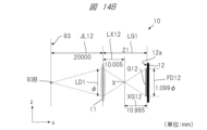
- Figure 14B is a diagram showing the spread of image blur when a distant object is imaged using a wide-angle imaging system. Note that in Figures 14A and 14B, the direction of the principal axis of the optical system is the x-direction, and the direction perpendicular to the x-direction is the y-direction.
- the standard imaging system 10 which is a wide-angle imaging system, has a standard optical system 11, which is a wide-angle optical system, and an imaging element 12, which are spaced apart in the x direction.
- the focal length f of the standard optical system 11 is 10 mm and the focal distance is 19.1 mm
- LG1 the distance from the standard optical system 11 to the light receiving surface 12a of the imaging element 12
- LG1 the distance from the standard optical system 11 to the light receiving surface 12a of the imaging element 12
- LG1 the distance from the standard optical system 11 to the light receiving surface 12a of the imaging element 12
- LG1 the distance from the standard optical system 11 to the light receiving surface 12a of the imaging element 12
- LG1 the distance from the standard optical system 11 to the light receiving surface 12a of the imaging element 12
- the optical system diameter LD1 ⁇ .
- the blur diameter FD11 (distance XG11/distance LX11) x optical system diameter LD1
- the blur diameter FD12 (distance XG12 / distance LX12) ⁇ optical system diameter LD1
- the pixel pitch PP of the image sensor 12 1.2 ⁇ m.
- the depth of the subject 93 is 10,000 mm and when it is 20,000 mm, the number of pixels corresponding to the blur diameter appearing on the light receiving surface 12a of the image sensor 12 is the same, and the difference in depth is not reflected in the number of pixels. In other words, it is difficult to distinguish between subject depths of 10,000 mm and 20,000 mm. Therefore, it can be understood that the accuracy of estimating the depth of a distant object using a wide-angle imaging system is low.
- Figure 15A is a diagram showing the spread of image blur when a close object is imaged using a telephoto imaging system.
- Figure 15B is a diagram showing the spread of image blur when a distant object is imaged using a telephoto imaging system.
- the direction of the principal axis of the optical system is the x-direction
- the direction perpendicular to the x-direction is the y-direction.
- telephoto imaging system 20 which is a telephoto type imaging system, has telephoto optical system 21 and image sensor 22, which are telephoto type optical systems arranged at an interval in the x direction.
- the focal length f of telephoto optical system 21 is 40 mm and the focal length is 66.7 mm
- the diameter of telephoto optical system 21 is represented by LD2
- the optical system diameter LD2 ⁇ .
- the pixel pitch PP of the image sensor 22 1.2 ⁇ m.
- the difference in the number of pixels corresponding to the blur diameter appearing on the light receiving surface 22a of the image sensor 22 is four pixels, and the difference in depth is reflected in the number of pixels.
- the imaging device according to embodiment 1 of the present application includes a first imaging system having a first angle of view, a second imaging system having a second angle of view narrower than the first angle of view, and an arithmetic and control unit connected to the first imaging system and the second imaging system, and the arithmetic and control unit performs a first imaging process of encoding and imaging an object using the first imaging system to obtain a first captured image, a detection process of detecting a specific object included in the object and having a distance from the first imaging system equal to or greater than a threshold based on the obtained first captured image, a second imaging process of encoding and imaging the detected specific object using the second imaging system to obtain a second captured image, a first decoding process of decoding the first captured image to obtain first depth information representing the depth of an object at each position of the object, and a second decoding process of decoding the second captured image to obtain
- the imaging device may be an imaging device that includes a first imaging system having a first angle of view, a second imaging system having a second angle of view narrower than the first angle of view, and an arithmetic and control unit connected to the first imaging system and the second imaging system, and the arithmetic and control unit performs a first imaging process of encoding and imaging a subject using the first imaging system to obtain a first captured image, a first decoding process of decoding the first captured image to obtain a first decoded image representing the subject and first depth information representing the depth of an object at each position of the subject, a detection process of detecting a specific object included in the subject and located at a distance from the first imaging system equal to or greater than a threshold based on the first decoded image, a second imaging process of encoding and imaging the detected specific object using the second imaging system to obtain a second captured image, and a second decoding process of decoding the second captured image to obtain second depth information representing the depth of the specific object.
- the imaging device is characterized in that an image captured by a wide-angle imaging system is used to estimate the depth of the entire subject, and an image captured by a telephoto imaging system is used to estimate the depth of a specific distant object of interest.
- FIG. 1 is a diagram showing an example of installation of an imaging device according to embodiment 1.
- the imaging device 1 is installed in an automobile 100.
- the imaging device 1 is configured to capture an image of a subject 90 in front of the automobile 100.
- the subject 90 includes a leading vehicle that is a vehicle traveling in front of the automobile 100.
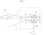
- FIG. 2 is a diagram showing an example of the configuration of the imaging device 1.
- the imaging device 1 has a standard imaging system 10, a telephoto imaging system 20, a calculation and control unit 30, an operation unit 37, and a display unit 38.
- the standard imaging system 10, the telephoto imaging system 20, the operation unit 37, and the display unit 38 are each connected to the calculation and control unit 30.
- the standard imaging system 10 is an example of the "first imaging system” in this application.
- the telephoto imaging system 20 is an example of the “second imaging system” in this application.
- the calculation and control unit 30 is an example of the "calculation and control unit” in this application.
- the standard imaging system 10 is a wide-angle imaging system having a first angle of view ⁇ . The configuration of the standard imaging system 10 will be described.
- FIG. 3 is a diagram showing an example of the configuration of the standard imaging system 10. As shown in FIG. 3, the standard imaging system 10 has a standard optical system 11, an imaging element 12, and a mask M1.
- the standard optical system 11 is, for example, a wide-angle lens with a relatively wide angle of view.
- the standard optical system collects light L coming from the subject 90 and forms an image on the light receiving surface 12a of the image sensor 12.
- the mask M1 is an optical filter that passes a portion of the light L incident on the standard optical system 11 and blocks the other portion of the light L.
- the mask M1 is placed in a light entrance area where the light L enters the standard optical system 11 from the subject 90.
- the mask M1 is placed, for example, on the subject 90 side of the standard optical system 11.
- the mask M1 may be placed inside the standard optical system 11.
- the "mask” is also called a "coded aperture,” “coded stop,” “aperture,” etc.
- the imaging element 12 is an electronic component that performs photoelectric conversion, and has a large number of photoelectric conversion elements arranged two-dimensionally.
- the large number of photoelectric conversion elements form a light receiving surface 12a.
- the imaging element 12 photoelectrically converts the light and darkness of the image formed on the light receiving surface 12a into an amount of electric charge.
- the imaging element 12 outputs data of a standard captured image P1 representing the subject 90.
- the imaging is performed, for example, by a rolling shutter method or a global shutter method.
- the standard captured image P1 is an example of a "first captured image" in this application.
- the “imaging element” is also called an “image sensor.”
- the imaging element 12 is, for example, a CCD (Charge Coupled Devices) image sensor or a COMS (Complementary Metal Oxide Semiconductor) image sensor.
- Light L arriving from a point image h1 on the surface 90a of the subject 90 passes through the mask M1 and is encoded with a point spread function f1, enters the standard optical system 11, and the light L passing through the standard optical system 11 forms a blurred image on the light receiving surface 12a of the image sensor 12.
- This blurred image is encoded with the point spread function f1 that is specific to the standard imaging system 10 that includes the mask M1.
- the telephoto imaging system 20 is a telephoto type imaging system having a second angle of view ⁇ narrower than the first angle of view ⁇ . The configuration of the telephoto imaging system 20 will be described.
- FIG. 4 is a diagram showing an example of the configuration of the telephoto imaging system 20.
- the telephoto imaging system 20 has a telephoto optical system 21, an image sensor 22, a mask M2, a light reflecting tube 23, and an imaging direction changing unit 24.
- the light reflecting tube 23 is an example of a "reflecting unit” in this application.
- the imaging direction changing unit 24 is an example of a "changing unit” in this application.
- the telephoto optical system 21 is, for example, a telephoto lens with a relatively narrow angle of view.
- the telephoto optical system 21 collects light L coming from a specific object of the subject 90 that is located in the imaging direction of the telephoto imaging system 20, and forms an image on the light receiving surface 22a of the imaging element 22.
- the telephoto optical system 21 may be an optical zoom lens, or the standard imaging system 10 may be provided with an optical zoom function and used as the telephoto imaging system 20.
- Mask M2 has the same configuration and function as mask M1, and is an optical filter for light L entering the telephoto optical system 21.
- Mask M2 is placed in the light entrance area where light L enters the telephoto optical system 21 from the subject 90.
- Mask M2 is placed, for example, on the subject 90 side of the telephoto optical system 21.
- Mask M2 may be placed inside the telephoto optical system 21.
- the image sensor 22 has the same configuration and function as the image sensor 12, and when an image is captured, it outputs data of a telephoto captured image P2 represented by an image formed on the light receiving surface 22a.
- the telephoto captured image P2 is an example of a "second captured image" in this application.
- the light reflecting tube 23 is a cylindrical member with a light reflecting surface formed on the inside.
- the light reflecting tube 23 is disposed on the subject side of the telephoto optical system 21, and is configured so that it can move a small distance in a direction perpendicular to the x direction, which is the main axial direction of the telephoto optical system 21.
- the cross-sectional shape of the light reflecting tube 23 taken in a direction perpendicular to the x direction is, for example, circular or rectangular.
- the light reflecting tube 23 is an example of a "reflective portion" in this application.
- the reference position of the light reflecting tube 23 is the position where the central axis of the light reflecting tube 23 and the main axis of the telephoto optical system 21 overlap.
- the light reflecting tube 23 is located at the reference position, the light L coming from the point image h1 on the surface 90a of the subject 90 is reflected by the inner reflecting surface of the light reflecting tube 23, passes through the mask M2 and enters the telephoto optical system 21.
- the light L that passes through the telephoto optical system 21 is focused as a blurred image at position g1 on the light receiving surface 22a of the image sensor 22. This blurred image is encoded with the point spread function f2 that is specific to the telephoto imaging system 20 including the mask M2.
- the light reflecting tube 23 when the light reflecting tube 23 is positioned at a position displaced from the reference position, the light L coming from a point image h2 at a position different from the point image h1 on the surface 90a of the subject 90 is reflected by the inner reflecting surface of the light reflecting tube 23, passes through the mask M2, is encoded, and enters the telephoto optical system 21.
- the light L that passes through the telephoto optical system 21 is focused as a blurred image at position g1 on the light receiving surface 22a of the image sensor 22.
- the imaging direction of the telephoto imaging system 20 changes. In other words, by controlling the position of the light reflecting tube 23, it becomes possible to control the imaging direction of the telephoto imaging system 20.
- the imaging direction change unit 24 changes the position of the light reflecting tube 23 relative to the telephoto optical system 21 in a direction perpendicular to the x direction.
- the imaging direction change unit 24 is connected to the calculation control unit 30.
- the imaging direction change unit 24 controls the imaging direction of the telephoto imaging system 20 by moving the light reflecting tube 23 and changing the position of the light reflecting tube 23 based on a control signal sent from the calculation control unit 30.
- the imaging direction change unit 24 is an example of a "change unit" in this application.
- the imaging direction change unit 24 moves the light reflecting tube 23 by a mechanism using, for example, a motor, an electrostatic actuator, or the like as a drive source.
- the imaging direction change unit 24 may be configured, for example, by MEMS (Micro Electro Mechanical Systems).
- the imaging direction change unit 24 may change the imaging direction of the telephoto imaging system 20 by moving a part or all of the telephoto optical system 21.
- FIG. 5 is a diagram showing an example of the configuration of the calculation control unit 30.
- the calculation control unit 30 is, for example, a computer, and as shown in FIG. 5, has a processor 31, a memory 32, and an interface 33.
- the processor 31 is, for example, a CPU (Central Processing Unit), an MPU (Micro-Processing Unit), a microcontroller, or a GPU (Graphics Processing Unit).
- a CPU Central Processing Unit
- MPU Micro-Processing Unit
- microcontroller or a GPU (Graphics Processing Unit).
- GPU Graphics Processing Unit
- Memory 32 is, for example, a semiconductor storage device, and may include a magnetic disk, an optical disk, etc.
- Program P is stored in memory 32, and processor 31 reads and executes program P to perform various processes.
- the interface 33 is connected to the image sensors 12 and 22, the image capture direction change unit 24, the processor 31, the external device 2, etc., and mediates the sending and receiving of signals and data between these devices.
- calculation control unit 30 when the calculation control unit 30 is a computer, all or part of the computer may be composed of semiconductor circuits such as a DSP (Digital Signal Processor), an ASIC (Application Specific Integrated Circuit), an FPGA (Field Programmable Gate Array), or a CPLD (Complex Programmable Logic Device).
- the calculation control unit 30 may also include electronic circuits such as an image processing engine that processes data output from the image sensors 12 and 22.
- FIG. 6 is a diagram showing a schematic diagram of various processes performed by the calculation control unit.
- the calculation control unit 30 uses a wide-angle standard imaging system 10 to capture an encoded image of the subject 90, and obtains a standard captured image P1, which is an image representing the subject 90, from the standard imaging system 10.
- the calculation control unit 30 detects a distant vehicle ahead 92 as a specific distant object included in the subject 90 based on the obtained standard captured image P1.
- the calculation control unit 30 controls the imaging direction of the telephoto imaging system 20 so that the detected distant vehicle ahead 92 can be captured in an encoded manner using the telephoto imaging system 20.
- the calculation control unit 30 then uses the telephoto imaging system 20 to capture an encoded image of the distant vehicle ahead 92, and obtains a telephoto captured image P2, which is an image representing the detected distant vehicle ahead 92, from the telephoto imaging system 20.
- the calculation control unit 30 decodes the obtained standard captured image P1 to obtain a standard decoded image Q1 representing the subject 90 with improved blurring, and standard depth information D1 representing the depth of objects corresponding to each position of the subject 90 represented by the standard decoded image Q1.
- the calculation control unit 30 also decodes the obtained telephoto captured image P2 to obtain a telephoto decoded image Q2 representing the distant vehicle in front 92 with improved blurring, and telephoto depth information D2 representing the depth of objects corresponding to each position of the distant vehicle in front 92 represented by the telephoto decoded image Q2.
- the standard decoded image Q1 is an example of a "first decoded image” in this application.
- the telephoto decoded image Q2 is an example of a "second decoded image” in this application.
- the calculation control unit 30 generates a standard depth map DM1 by associating each position of the standard decoded image Q1 with the depth of each position of the subject 90 represented by the standard depth information D1.
- the calculation control unit 30 also generates a telephoto depth map DM2 by associating each position of the telephoto decoded image Q2 with the depth of each position of the vehicle in front 92 represented by the telephoto depth information D2.
- the calculation control unit 30 then superimposes the telephoto depth map DM2 on the standard depth map DM1 to combine the two depth maps and generate a depth map DM3.
- the standard depth map DM1 is an example of a "first depth map” in this application.
- the telephoto depth map DM2 is an example of a "second depth map” in this application.
- the process of generating the standard depth map DM1 is an example of a "first generation process” in this application.
- the process of generating the telephoto depth map DM2 is an example of a "second generation process” in this application.
- FIG. 7 is a diagram showing how depth map DM3 is generated.
- depth map DM3 is generated by superimposing telephoto depth map DM2 on standard depth map DM1.
- Depth map DM3 uses telephoto depth information D2 with high depth estimation accuracy for the image portion of the distant vehicle in front 92, so it is a depth map that accurately reflects the depth of the distant vehicle in front 92.
- vehicle in front 92 is an example of a "vehicle in front" in this application.
- the calculation control unit 30 may generate the depth map DM3 based on the standard decoded image Q1 and the standard depth information D1, or based on the standard depth map DM1 and the telephoto depth information D2.
- the depth map DM3 is a depth map in which the image portion representing the distant leading vehicle 92 in the standard decoded image Q1 representing the subject 90 is associated with a depth based on the telephoto depth information D2, and the other image portions are associated with a depth based on the standard depth information D1.
- the calculation control unit 30 outputs the generated depth map DM3 to an external device 2 connected to the imaging device 1.
- the external device 2 is, for example, a driving assistance device, and uses the depth map DM3 to provide driving assistance for the automobile 100.
- the calculation control unit 30 accepts commands and information input based on the user's operation of the operation unit 37.
- the calculation control unit 30 also causes the display unit 38 to display information intended for the user.
- the operation unit 37 may be, for example, a key, a button, a dial, etc.
- the display unit 38 may be, for example, a liquid crystal panel, an organic EL panel, etc.
- the operation unit 37 and the display unit 38 may be configured as an integrated unit, and may be, for example, a touch panel.
- the calculation control unit 30 uses a known detection method, such as template matching or an image detection method using artificial intelligence (AI).
- a known detection method such as template matching or an image detection method using artificial intelligence (AI).
- Whether or not a specific object exists in the distance i.e., whether or not the distance from the standard imaging system 10 to the specific object is equal to or greater than a threshold, is determined, for example, based on the size or number of pixels of the image representing the specific object. For example, if it is determined that the ratio of the size of the image representing the specific object to the size of the standard imaging image P1 is equal to or less than a first threshold set in advance, the specific object is determined to be in the distance. Also, for example, if it is determined that the number of pixels constituting the image representing the specific object is equal to or less than a second threshold set in advance, the specific object is determined to be in the distance.
- Another method is to determine whether a particular object is located far away based on the standard depth map DM1.
- the calculation control unit 30 is configured to store the characteristics of a specific object that exists in the distance so that an image showing the specific object can be detected in the image showing the subject 90.
- the specific object to be detected is the automobile traveling ahead.
- the user inputs and stores into the calculation control unit 30 one of the characteristics of the automobile traveling ahead, that is, the two tail lamps arranged horizontally at a distance from each other at the rear of the automobile.
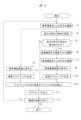
- FIG. 8 is a flow diagram showing an example of processing in the imaging device according to the first embodiment.
- step S1 encoded imaging is performed using a standard imaging system.
- the calculation control unit 30 performs a first encoded imaging process in which the subject 90 is encoded and imaged using the standard imaging system 10 to obtain a standard captured image P1.
- steps S2 to S3 and steps S4 to S9 are performed.
- steps S2 to S3 and steps S4 to S9 may be performed in parallel, or may be performed in order according to a set priority order.
- step S2 the standard captured image is decoded.
- the calculation control unit 30 performs a first decoding process in which the standard captured image P1 is decoded by deconvolution based on the point spread function f1. Through this decoding, the calculation control unit 30 obtains a standard decoded image Q1 in which the blur of the subject 90 has been improved, and standard depth information D1 that represents the depth estimate of the object at each position of the subject 90 represented by the standard decoded image Q1.
- step S3 a standard depth map is generated.
- the calculation control unit 30 performs a first depth map generation process in which the calculation control unit 30 associates each position of the standard decoded image Q1 with the depth estimate of the object at each position of the subject 90 represented by the standard depth information D1, thereby generating a standard depth map DM1.
- step S4 a search is performed for a specific object in the distance.
- the calculation control unit 30 performs a specific object search process to search for a leading vehicle 92 in the distance as a specific object in the distance in the standard captured image P1.
- step S5 it is determined whether a specific distant object has been detected. Specifically, the calculation control unit 30 performs a search determination process to determine whether a distant vehicle ahead 92 has been detected as a specific distant object. If it is determined that the vehicle ahead 92 has been detected (S5: Yes), the calculation control unit 30 advances the processing step to step S6. On the other hand, if it is determined that the vehicle ahead 92 has not been detected (S5: No), the calculation control unit 30 advances the processing step to step S10.
- step S6 the imaging direction of the telephoto imaging system is adjusted.
- the calculation control unit 30 performs imaging direction control processing to control the imaging direction change unit 24 to adjust the imaging direction of the telephoto imaging system 20 so that the detected vehicle in front 92 can be imaged using the telephoto imaging system 20.
- step S7 encoded imaging is performed using the telephoto capture image.
- the calculation and control unit 30 performs a second encoded imaging process in which the telephoto capture system 20 is used to encode and capture the detected leading vehicle 92, thereby obtaining a telephoto capture image P2.
- step S8 the telephoto captured image is decoded.
- the calculation control unit 30 performs a second decoding process in which the telephoto captured image P2 is decoded by deconvolution based on the point spread function f2. Through this decoding, the calculation control unit 30 obtains a telephoto decoded image Q2 in which the blur of the vehicle in front 92 has been improved, and telephoto depth information D2 that represents the depth estimates of objects at each position of the vehicle in front 92 represented by the telephoto decoded image Q2.
- step S9 a telephoto depth map is generated.
- the calculation control unit 30 performs a second depth map generation process in which the calculation control unit 30 associates each position of the telephoto decoded image Q2 with the depth estimate of the object at each position of the vehicle in front 92 represented by the telephoto depth information D2, to generate a telephoto depth map DM2.
- step S10 if the processing of both steps S3 and S9 has been performed, the depth maps are synthesized. Specifically, the calculation control unit 30 performs a third depth map generation process in which the standard depth map DM1 obtained in step S3 is superimposed with the telephoto depth map DM2 obtained in step S9 to generate a depth map DM3. On the other hand, if only the processing of step S3 out of steps S3 and S9 has been performed, the standard depth map DM1 obtained in step S3 becomes the depth map DM3. Specifically, the calculation control unit 30 sets the standard depth map DM1 to the depth map DM3.
- step S11 the depth map is output. Specifically, the calculation control unit 30 performs an output process to output the depth map DM3 to the external device 2.
- step S12 a determination is made as to whether or not imaging should be continued. Specifically, the calculation control unit 30 performs a continuation determination process to determine whether or not imaging should be continued based on whether an imaging stop command has been input, whether or not an error has occurred, etc. If it is determined that imaging should be continued (S12: Yes), the calculation control unit 30 returns the processing step to step S1, and imaging is continued. On the other hand, if it is determined that imaging should not be continued (S12: No), the calculation control unit 30 ends imaging.
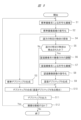
- Fig. 9 is a flow diagram showing a modified example of the processing in the imaging device according to the first embodiment.
- steps S1 to S2 are performed, step S3 and steps S4 to S9 may be performed.
- the search for a specific distant object in step S4 is performed based on a decoded image P3 obtained by decoding the standard captured image P1 in step S2.
- the other steps are the same as the steps in the flow diagram shown in Fig. 8, and therefore description thereof will be omitted here.
- the entire subject is encoded and imaged using a standard imaging system with a wide angle of view, and a specific distant object within the subject is encoded and imaged using a telephoto imaging system with a narrow angle of view.
- the decrease in depth estimation accuracy is suppressed.
- This type of encoded imaging can improve the depth estimation accuracy for distant objects whose depth estimation accuracy is likely to decrease. In other words, it is possible to generate a depth map in which the depth estimation accuracy does not decrease for distant objects that are of interest among the subject. As a result, it is possible to further increase the practicality of the depth estimation technology using DFD.
- Each of the masks M1 and M2 may be a combination of a plurality of masks.
- the mask M1 may include a mask M11 and a mask M12 having different geometric patterns of openings
- the mask M2 may include a mask M21 and a mask M22 having different geometric patterns of openings.
- the first coding imaging process using the standard imaging system 10 includes coding imaging using the mask M11 and coding imaging using the mask M12.
- the second coding imaging using the telephoto imaging system 20 includes coding imaging using the mask M21 and coding imaging using the mask M22.
- the first decoding process includes decoding the multiple captured images obtained by the first encoding imaging by deconvolution based on the point spread function specific to each of the masks M11 and M12.
- the second decoding process includes decoding the multiple captured images obtained by the second encoding imaging by deconvolution based on the point spread function specific to each of the masks M21 and M22.
- the subject depth map DM3 is obtained by combining the first depth map obtained by the first decoding process and the second depth map obtained by the second decoding process.
- Masks M11, M12 and masks M21, M22 are each realized, for example, by a liquid crystal optical shutter. Forming each mask or leaving it maskless can be achieved by controlling the on/off state of each segment of the liquid crystal in the liquid crystal optical shutter.
- FIG. 11 is a diagram showing an example of a liquid crystal light shutter that realizes multiple masks.
- the liquid crystal shutter LS has a light shielding portion BM and segments R1 to R3 that can select a light shielding state (on state in the case of normally white, off state in the case of normally black) and a light transmitting state (off state in the case of normally white, on state in the case of normally black).
- the light shielding portion BM is disposed on the outer periphery of the light entrance region R of the light that enters the optical system.
- the combined region of segments R1 to R3 corresponds to the light entrance region R.
- segment R1 corresponds to the circular region located at the top right of the light entrance region
- segment R2 corresponds to the circular region located at the bottom left of the light entrance region
- segment R3 corresponds to the region obtained by removing segments R1 and R2 from the light entrance region R.
- Segments R1 to R3 are controlled to be turned on and off based on the input signal to their corresponding electrodes.
- masks M11 or M12 can be realized in which the circular area corresponding to segment R1 has an opening.
- masks M21 and M22 can be realized in which the circular area corresponding to segment R2 has an opening.
- a no-mask state can be realized.
- the search process for searching for a specific object may be performed on the image captured using the mask M11 or the image captured using the mask M12, the decoded image obtained by the first decoding, or the image captured without a mask.
- the subject depth estimation method according to embodiment 2 is a subject depth estimation method that performs encoding imaging of a subject using a first imaging system having a first angle of view to obtain a first captured image, detects a specific object that is included in the subject and is at a distance from the first imaging system equal to or greater than a threshold based on the first captured image, performs encoding imaging of the detected specific object using a second imaging system having a second angle of view narrower than the first angle of view to obtain a second captured image, decodes the first captured image and the second captured image, and obtains depth information of the subject and depth information of the specific object.
- the subject depth estimation method may be a subject depth estimation method that performs encoding imaging of a subject using a first imaging system having a first angle of view, obtains a first captured image, decodes the first captured image, obtains a first decoded image representing the subject and depth information of the subject, detects a specific object included in the subject and located at a distance from the first imaging system equal to or greater than a threshold based on the first decoded image, performs encoding imaging of the detected specific object using a second imaging system having a second angle of view narrower than the first angle of view, obtains a second captured image, decodes the second captured image, and obtains depth information of the specific object.
- this subject depth estimation method can provide a more practical DFD technology. More specifically, this subject depth estimation method can generate a depth map that does not reduce depth estimation accuracy for distant objects that are of interest among subjects. As a result, it is possible to improve the practicality of DFD-based depth estimation technology.
- the program according to the third embodiment is a program for causing a computer to execute the following processes: encoding and capturing an image of a subject using a first imaging system having a first angle of view to obtain a first captured image; detecting a specific object that is included in the subject and is at a distance from the first imaging system equal to or greater than a threshold based on the first captured image; encoding and capturing the detected specific object using a second imaging system having a second angle of view narrower than the first angle of view to obtain a second captured image; and decoding the first captured image and the second captured image to obtain depth information of the subject and depth information of the specific object.
- the program according to the third embodiment may be a program for causing a computer to execute the following processes: encoding and capturing an image of a subject using a first imaging system having a first angle of view to obtain a first captured image; decoding the first captured image to obtain a first decoded image representing the subject and depth information of the subject; detecting a specific object that is included in the subject and whose distance from the first imaging system is equal to or greater than a threshold based on the first decoded image; encoding and capturing the detected specific object using a second imaging system having a second angle of view narrower than the first angle of view to obtain a second captured image; and decoding the second captured image to obtain depth information of the specific object.
- the program may also be a program for determining whether or not a specific object is present in the distance based on the standard depth map DM1.
- This program may be a program for causing a computer to function as the arithmetic control unit 30 of the imaging device according to embodiment 1. Also, this program may be a program for causing a computer to execute the subject depth estimation method according to embodiment 2.
- non-transitory, tangible, computer-readable recording medium on which the above program is recorded is also an embodiment of the present invention.
- Such a program can provide a more practical DFD technology, as in the first embodiment. More specifically, this program can generate a depth map in which the accuracy of depth estimation does not decrease for distant objects that are of interest among subjects, as in the first embodiment, by executing the program on a computer. As a result, it becomes possible to improve the practicality of the depth estimation technology using DFD.
- the present invention is not limited to the above-mentioned embodiments and includes various modified examples. Furthermore, the above-mentioned embodiments have been described in detail to clearly explain the present invention, and are not necessarily limited to those having all of the configurations described. Furthermore, it is possible to replace part of the configuration of one embodiment with the configuration of another embodiment, and it is also possible to add the configuration of another embodiment to the configuration of one embodiment. All of these belong to the scope of the present invention. Furthermore, the numerical values etc. contained in the text and figures are merely examples, and the effect of the present invention will not be impaired if different ones are used.
Landscapes
- Engineering & Computer Science (AREA)
- Physics & Mathematics (AREA)
- General Physics & Mathematics (AREA)
- Theoretical Computer Science (AREA)
- Multimedia (AREA)
- Computer Vision & Pattern Recognition (AREA)
- Signal Processing (AREA)
- Remote Sensing (AREA)
- Radar, Positioning & Navigation (AREA)
- Electromagnetism (AREA)
- Computing Systems (AREA)
- Studio Devices (AREA)
- Image Processing (AREA)
Priority Applications (2)
| Application Number | Priority Date | Filing Date | Title |
|---|---|---|---|
| JP2024551262A JPWO2024079998A1 (https=) | 2022-10-13 | 2023-08-23 | |
| US19/175,146 US20250238943A1 (en) | 2022-10-13 | 2025-04-10 | Imaging device, method of estimating subject depth, and program |
Applications Claiming Priority (2)
| Application Number | Priority Date | Filing Date | Title |
|---|---|---|---|
| JP2022164826 | 2022-10-13 | ||
| JP2022-164826 | 2022-10-13 |
Related Child Applications (1)
| Application Number | Title | Priority Date | Filing Date |
|---|---|---|---|
| US19/175,146 Continuation US20250238943A1 (en) | 2022-10-13 | 2025-04-10 | Imaging device, method of estimating subject depth, and program |
Publications (1)
| Publication Number | Publication Date |
|---|---|
| WO2024079998A1 true WO2024079998A1 (ja) | 2024-04-18 |
Family
ID=90669368
Family Applications (1)
| Application Number | Title | Priority Date | Filing Date |
|---|---|---|---|
| PCT/JP2023/030341 Ceased WO2024079998A1 (ja) | 2022-10-13 | 2023-08-23 | 撮像装置、被写体奥行き推定方法、およびプログラム |
Country Status (3)
| Country | Link |
|---|---|
| US (1) | US20250238943A1 (https=) |
| JP (1) | JPWO2024079998A1 (https=) |
| WO (1) | WO2024079998A1 (https=) |
Citations (2)
| Publication number | Priority date | Publication date | Assignee | Title |
|---|---|---|---|---|
| JP2017103695A (ja) * | 2015-12-04 | 2017-06-08 | キヤノン株式会社 | 画像処理装置、画像処理方法、及びそのプログラム |
| JP2021043230A (ja) * | 2017-12-26 | 2021-03-18 | 富士フイルム株式会社 | ワイドコンバージョンレンズ及び撮像装置 |
-
2023
- 2023-08-23 WO PCT/JP2023/030341 patent/WO2024079998A1/ja not_active Ceased
- 2023-08-23 JP JP2024551262A patent/JPWO2024079998A1/ja active Pending
-
2025
- 2025-04-10 US US19/175,146 patent/US20250238943A1/en active Pending
Patent Citations (2)
| Publication number | Priority date | Publication date | Assignee | Title |
|---|---|---|---|---|
| JP2017103695A (ja) * | 2015-12-04 | 2017-06-08 | キヤノン株式会社 | 画像処理装置、画像処理方法、及びそのプログラム |
| JP2021043230A (ja) * | 2017-12-26 | 2021-03-18 | 富士フイルム株式会社 | ワイドコンバージョンレンズ及び撮像装置 |
Non-Patent Citations (2)
| Title |
|---|
| NAGAHARA, HAJIME: "Computational Photography", THE JOURNAL OF THE INSTITUTE OF IMAGE INFORMATION AND TELEVISION ENGINEERS, EIZO JOHO MEDIA GAKKA, JP, vol. 73, no. 3, 1 May 2019 (2019-05-01), JP , pages 460 - 468, XP009554099, ISSN: 1342-6907, DOI: 10.3169/itej.73.460 * |
| YUICHI TAKEDA, SHINSAKU HIURA, KOSUKE SATO: "Fusion of Depth from Defocus using coded aperture and stereo method", IEICE TRANSACTIONS ON INFORMATION AND SYSTEMS, DENSHI JOUHOU TSUUSHIN GAKKAI, JOUHOU SHISUTEMU SOSAIETI, JP, vol. J96-D, no. 8, 1 August 2013 (2013-08-01), JP , pages 1688 - 1700, XP009551652, ISSN: 1880-4535 * |
Also Published As
| Publication number | Publication date |
|---|---|
| US20250238943A1 (en) | 2025-07-24 |
| JPWO2024079998A1 (https=) | 2024-04-18 |
Similar Documents
| Publication | Publication Date | Title |
|---|---|---|
| JP6724982B2 (ja) | 信号処理装置および撮像装置 | |
| EP3787281B1 (en) | Dual aperture zoom camera with video support and switching / non-switching dynamic control | |
| CN102959586B (zh) | 深度推测装置以及深度推测方法 | |
| JP5437855B2 (ja) | 障害物検知装置およびそれを備えた障害物検知システム、並びに障害物検知方法 | |
| JP7620005B2 (ja) | 撮像装置及び電子機器 | |
| JP2017021253A (ja) | カメラシステム、そのブレ補正方法、カメラボディ、及び交換レンズ | |
| JP2020501423A (ja) | 車両の周辺領域を状況に依存した捕捉を実施するためのカメラ手段及び方法 | |
| CN110365878A (zh) | 一种摄像装置和方法 | |
| US11056518B2 (en) | Imaging apparatus and imaging method | |
| JP2016219974A (ja) | 撮影装置及び撮影方法、画像処理装置及び画像処理方法、並びにプログラム | |
| US20180338095A1 (en) | Imaging system and moving body control system | |
| JP2015207278A (ja) | 視差値導出装置、機器制御システム、移動体、ロボット、視差値導出方法、およびプログラム | |
| JP2020115515A (ja) | 撮像装置及び電子機器 | |
| JP4258539B2 (ja) | 複数画角カメラ | |
| JP2021158668A (ja) | 撮像制御装置及び移動体 | |
| JP2018005891A (ja) | 画像処理装置、撮像装置、画像処理方法、及びプログラム | |
| US20250124585A1 (en) | Imaging apparatus, subject depth estimation method, and program | |
| WO2024079998A1 (ja) | 撮像装置、被写体奥行き推定方法、およびプログラム | |
| CN107925719B (zh) | 摄像装置、摄像方法、及非暂时性记录介质 | |
| WO2016072300A1 (ja) | 車両周辺画像表示装置、車両周辺画像表示方法 | |
| US20250126369A1 (en) | Imaging apparatus, depth map generation method, and program | |
| JP2013054193A (ja) | ブレ補正装置及び光学機器 | |
| JP2015194388A (ja) | 撮像装置および撮像システム | |
| JP2006308496A (ja) | 測距装置及び撮像装置 | |
| JP2019092036A (ja) | 撮像装置及び制御方法 |
Legal Events
| Date | Code | Title | Description |
|---|---|---|---|
| 121 | Ep: the epo has been informed by wipo that ep was designated in this application |
Ref document number: 23877006 Country of ref document: EP Kind code of ref document: A1 |
|
| WWE | Wipo information: entry into national phase |
Ref document number: 2024551262 Country of ref document: JP |
|
| NENP | Non-entry into the national phase |
Ref country code: DE |
|
| 122 | Ep: pct application non-entry in european phase |
Ref document number: 23877006 Country of ref document: EP Kind code of ref document: A1 |