WO2024079963A1 - 電子部品及び成膜方法 - Google Patents
電子部品及び成膜方法 Download PDFInfo
- Publication number
- WO2024079963A1 WO2024079963A1 PCT/JP2023/027615 JP2023027615W WO2024079963A1 WO 2024079963 A1 WO2024079963 A1 WO 2024079963A1 JP 2023027615 W JP2023027615 W JP 2023027615W WO 2024079963 A1 WO2024079963 A1 WO 2024079963A1
- Authority
- WO
- WIPO (PCT)
- Prior art keywords
- element body
- protective film
- external electrode
- film
- polishing
- Prior art date
- Legal status (The legal status is an assumption and is not a legal conclusion. Google has not performed a legal analysis and makes no representation as to the accuracy of the status listed.)
- Ceased
Links
Images




Classifications
-
- H—ELECTRICITY
- H01—ELECTRIC ELEMENTS
- H01C—RESISTORS
- H01C17/00—Apparatus or processes specially adapted for manufacturing resistors
- H01C17/06—Apparatus or processes specially adapted for manufacturing resistors adapted for coating resistive material on a base
- H01C17/075—Apparatus or processes specially adapted for manufacturing resistors adapted for coating resistive material on a base by thin-film techniques
- H01C17/14—Apparatus or processes specially adapted for manufacturing resistors adapted for coating resistive material on a base by thin-film techniques by chemical deposition
- H01C17/18—Apparatus or processes specially adapted for manufacturing resistors adapted for coating resistive material on a base by thin-film techniques by chemical deposition without using electric current
-
- H—ELECTRICITY
- H01—ELECTRIC ELEMENTS
- H01C—RESISTORS
- H01C1/00—Details
- H01C1/14—Terminals or tapping points specially adapted for resistors; Arrangements of terminals or tapping points on resistors
-
- H—ELECTRICITY
- H01—ELECTRIC ELEMENTS
- H01C—RESISTORS
- H01C1/00—Details
- H01C1/14—Terminals or tapping points specially adapted for resistors; Arrangements of terminals or tapping points on resistors
- H01C1/1413—Terminals or electrodes formed on resistive elements having negative temperature coefficient
-
- H—ELECTRICITY
- H01—ELECTRIC ELEMENTS
- H01C—RESISTORS
- H01C1/00—Details
- H01C1/14—Terminals or tapping points specially adapted for resistors; Arrangements of terminals or tapping points on resistors
- H01C1/142—Terminals or tapping points specially adapted for resistors; Arrangements of terminals or tapping points on resistors the terminals or tapping points being coated on the resistive element
-
- H—ELECTRICITY
- H01—ELECTRIC ELEMENTS
- H01C—RESISTORS
- H01C1/00—Details
- H01C1/14—Terminals or tapping points specially adapted for resistors; Arrangements of terminals or tapping points on resistors
- H01C1/148—Terminals or tapping points specially adapted for resistors; Arrangements of terminals or tapping points on resistors the terminals embracing or surrounding the resistive element
-
- H—ELECTRICITY
- H01—ELECTRIC ELEMENTS
- H01C—RESISTORS
- H01C17/00—Apparatus or processes specially adapted for manufacturing resistors
- H01C17/28—Apparatus or processes specially adapted for manufacturing resistors adapted for applying terminals
- H01C17/281—Apparatus or processes specially adapted for manufacturing resistors adapted for applying terminals by thick film techniques
-
- H—ELECTRICITY
- H01—ELECTRIC ELEMENTS
- H01C—RESISTORS
- H01C17/00—Apparatus or processes specially adapted for manufacturing resistors
- H01C17/28—Apparatus or processes specially adapted for manufacturing resistors adapted for applying terminals
- H01C17/281—Apparatus or processes specially adapted for manufacturing resistors adapted for applying terminals by thick film techniques
- H01C17/283—Precursor compositions therefor, e.g. pastes, inks, glass frits
-
- H—ELECTRICITY
- H01—ELECTRIC ELEMENTS
- H01C—RESISTORS
- H01C7/00—Non-adjustable resistors formed as one or more layers or coatings; Non-adjustable resistors made from powdered conducting material or powdered semi-conducting material with or without insulating material
- H01C7/008—Thermistors
-
- H—ELECTRICITY
- H01—ELECTRIC ELEMENTS
- H01C—RESISTORS
- H01C7/00—Non-adjustable resistors formed as one or more layers or coatings; Non-adjustable resistors made from powdered conducting material or powdered semi-conducting material with or without insulating material
- H01C7/02—Non-adjustable resistors formed as one or more layers or coatings; Non-adjustable resistors made from powdered conducting material or powdered semi-conducting material with or without insulating material having positive temperature coefficient
-
- H—ELECTRICITY
- H01—ELECTRIC ELEMENTS
- H01C—RESISTORS
- H01C7/00—Non-adjustable resistors formed as one or more layers or coatings; Non-adjustable resistors made from powdered conducting material or powdered semi-conducting material with or without insulating material
- H01C7/04—Non-adjustable resistors formed as one or more layers or coatings; Non-adjustable resistors made from powdered conducting material or powdered semi-conducting material with or without insulating material having negative temperature coefficient
-
- H—ELECTRICITY
- H01—ELECTRIC ELEMENTS
- H01C—RESISTORS
- H01C7/00—Non-adjustable resistors formed as one or more layers or coatings; Non-adjustable resistors made from powdered conducting material or powdered semi-conducting material with or without insulating material
- H01C7/18—Non-adjustable resistors formed as one or more layers or coatings; Non-adjustable resistors made from powdered conducting material or powdered semi-conducting material with or without insulating material comprising a plurality of layers stacked between terminals
-
- H—ELECTRICITY
- H01—ELECTRIC ELEMENTS
- H01F—MAGNETS; INDUCTANCES; TRANSFORMERS; SELECTION OF MATERIALS FOR THEIR MAGNETIC PROPERTIES
- H01F27/00—Details of transformers or inductances, in general
- H01F27/28—Coils; Windings; Conductive connections
- H01F27/29—Terminals; Tapping arrangements for signal inductances
-
- H—ELECTRICITY
- H01—ELECTRIC ELEMENTS
- H01F—MAGNETS; INDUCTANCES; TRANSFORMERS; SELECTION OF MATERIALS FOR THEIR MAGNETIC PROPERTIES
- H01F27/00—Details of transformers or inductances, in general
- H01F27/28—Coils; Windings; Conductive connections
- H01F27/32—Insulating of coils, windings, or parts thereof
-
- H—ELECTRICITY
- H01—ELECTRIC ELEMENTS
- H01G—CAPACITORS; CAPACITORS, RECTIFIERS, DETECTORS, SWITCHING DEVICES, LIGHT-SENSITIVE OR TEMPERATURE-SENSITIVE DEVICES OF THE ELECTROLYTIC TYPE
- H01G4/00—Fixed capacitors; Processes of their manufacture
- H01G4/002—Details
- H01G4/224—Housing; Encapsulation
-
- H—ELECTRICITY
- H01—ELECTRIC ELEMENTS
- H01G—CAPACITORS; CAPACITORS, RECTIFIERS, DETECTORS, SWITCHING DEVICES, LIGHT-SENSITIVE OR TEMPERATURE-SENSITIVE DEVICES OF THE ELECTROLYTIC TYPE
- H01G4/00—Fixed capacitors; Processes of their manufacture
- H01G4/002—Details
- H01G4/228—Terminals
- H01G4/232—Terminals electrically connecting two or more layers of a stacked or rolled capacitor
-
- H—ELECTRICITY
- H01—ELECTRIC ELEMENTS
- H01G—CAPACITORS; CAPACITORS, RECTIFIERS, DETECTORS, SWITCHING DEVICES, LIGHT-SENSITIVE OR TEMPERATURE-SENSITIVE DEVICES OF THE ELECTROLYTIC TYPE
- H01G4/00—Fixed capacitors; Processes of their manufacture
- H01G4/30—Stacked capacitors
Definitions
- This disclosure relates to electronic components and film formation methods.
- the electronic component described in Patent Document 1 comprises an element body and an external electrode.
- the element body is made of ceramic.
- the external electrode covers a part of the outer surface of the element body.
- the external electrode is formed by applying a conductive paste containing glass powder to the outer surface of the element body and firing it.
- the element body has a reaction layer at the location where it comes into contact with the external electrode.
- the reaction layer is formed by reaction between the glass component contained in the conductive paste and the ceramic component of the element body. The presence of this reaction layer prevents the element body from being eroded by the plating solution and solder flux.
- an electronic component has an element body, an external electrode covering a part of the outer surface of the element body, and a protective film of aluminum oxide, the protective film being located between the element body and the external electrode, the thickness of the protective film in a direction perpendicular to the outer surface of the element body being taken as the film thickness, and when the protective film is viewed in cross section perpendicular to the outer surface of the element body at a location covered by the external electrode, the average and standard deviation of the film thickness are calculated within a range of 1 ⁇ m in a direction along the outer surface of the element body, and the ratio of the standard deviation to the average is 0.4 or more.
- a film forming method for forming a protective film, which is an aluminum oxide film, on the outer surface of an element body, and includes a laminate preparation step for preparing the element body, a first polishing step for polishing the element body with a first polishing powder, which is aluminum oxide powder, and a second polishing step for polishing the element body with a second polishing powder, which is aluminum oxide powder, after the first polishing step, and when the median particle size, which is the most frequent value of the particle size in the particle size distribution, is compared between the first polishing powder and the second polishing powder, the median particle size of the second polishing powder is 1/10 or less of the median particle size of the first polishing powder.
- the coefficient of variation of the thickness of the protective film is 0.4 or more, so the film thickness varies relatively widely. That is, the protective film has numerous irregularities on its outer surface. This creates an anchor effect, which improves the adhesion of the glass film to the protective film and the adhesion of the external electrodes to the glass film. In this way, if the layers stacked on the outer surface of the protective film have high adhesion, it is possible to prevent the plating solution, solder flux, etc. from penetrating through the boundaries between the layers. This makes it possible to suppress erosion of the element body by the plating solution, solder flux, etc.
- the outer surface of the protective film has numerous irregularities, the flow of metal particles in the protective film is suppressed during the curing process.
- the metal particles of the conductive paste are also restrained by the metal particles in the protective film, so the fluidity of the metal particles of the conductive paste is suppressed.
- the glass components are restrained in the gaps between the metal particles, so the glass components are less likely to flow to the outer surface of the molten conductive paste. Therefore, glass is less likely to precipitate on the surface of the external electrode after the conductive paste is fired.
- FIG. FIG. 3 is a cross-sectional view taken along line 3-3 in FIG. 2.
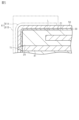
- FIG. 2 is an enlarged cross-sectional view of a protective film and its vicinity.
- FIG. 2 is an enlarged cross-sectional view of a protective film and its vicinity.
- 1 is a flowchart illustrating a method for manufacturing an electronic component.
- 1A to 1C are explanatory diagrams illustrating a manufacturing method of an electronic component.
- 1A to 1C are explanatory diagrams illustrating a manufacturing method of an electronic component.
- 1A to 1C are explanatory diagrams illustrating a manufacturing method of an electronic component.
- 1A to 1C are explanatory diagrams illustrating a manufacturing method of an electronic component.
- 1A to 1C are explanatory diagrams illustrating a manufacturing method of an electronic component.
- the electronic component 10 is, for example, a surface-mount type negative temperature coefficient thermistor component that is mounted on a circuit board, etc. Note that a negative temperature coefficient thermistor component has a characteristic that its resistance value decreases as the temperature increases.
- the electronic component 10 includes an element body 20.
- the element body 20 is generally rectangular prism-shaped and has a central axis CA.
- an axis extending along the central axis CA is defined as a first axis X.
- One of the axes perpendicular to the first axis X is defined as a second axis Y.
- An axis perpendicular to the first axis X and the second axis Y is defined as a third axis Z.
- One of the directions along the first axis X is defined as a first positive direction X1
- the direction along the first axis X opposite to the first positive direction X1 is defined as a first negative direction X2.
- One of the directions along the second axis Y is defined as a second positive direction Y1, and the direction along the second axis Y opposite to the second positive direction Y1 is defined as a second negative direction Y2.
- One of the directions along the third axis Z is defined as a third positive direction Z1, and the direction along the third axis Z opposite to the third positive direction Z1 is defined as a third negative direction Z2.
- the outer surface 21 of the element body 20 has six flat surfaces 22.
- the "surface” of the element body 20 here refers to a surface that can be observed when the entire element body 20 is observed. In other words, even if there are minute irregularities or steps that cannot be seen unless a part of the element body 20 is magnified and observed with a microscope, the surface is expressed as a flat surface or a curved surface.
- the six flat surfaces 22 extend in different directions.
- the six flat surfaces 22 are broadly divided into a first end surface 22A facing the first positive direction X1, a second end surface 22B facing the first negative direction X2, and four side surfaces 22C.
- the four side surfaces 22C are a surface facing the third positive direction Z1, a surface facing the third negative direction Z2, a surface facing the second positive direction Y1, and a surface facing the second negative direction Y2.
- the outer surface 21 of the element body 20 has 12 boundary surfaces 23.
- the boundary surfaces 23 include curved surfaces that exist at the boundaries between adjacent flat surfaces 22.
- the boundary surfaces 23 include curved surfaces that are formed, for example, by chamfering the corners formed by the adjacent flat surfaces 22.
- the outer surface 21 of the element body 20 also has eight spherical corner surfaces 24.
- the corner surfaces 24 are the boundaries between three adjacent flat surfaces 22.
- the corner surfaces 24 include curved surfaces at the intersections of the three boundary surfaces 23. That is, the corner surfaces 24 include curved surfaces formed, for example, by chamfering the corners formed by the three adjacent flat surfaces 22.
- the surface of a glass film 50 which will be described later, is identified with the outer surface 21 of the element body 20 and is given a reference number.
- the element body 20 has a larger dimension along the first axis X than along the third axis Z. Also, as shown in FIG. 1, the element body 20 has a larger dimension along the first axis X than along the second axis Y. Also, the material of the element body 20 is a ceramic made by sintering a metal oxide containing at least one of Mn, Fe, Ni, Co, Ti, Ba, Al, and Zn.
- the electronic component 10 has two first internal electrodes 41 and two second internal electrodes 42.
- the first internal electrodes 41 and the second internal electrodes 42 are embedded inside the element body 20.
- the material of the first internal electrode 41 is a conductive material.
- the material of the first internal electrode 41 is palladium.
- the material of the second internal electrode 42 is the same as the material of the first internal electrode 41.
- the first internal electrode 41 has a rectangular plate shape.
- the main surface of the first internal electrode 41 is perpendicular to the second axis Y.
- the second internal electrode 42 has the same rectangular plate shape as the first internal electrode 41.
- the main surface of the second internal electrode 42 is perpendicular to the second axis Y, similar to the first internal electrode 41.
- the dimension of the first internal electrode 41 in the direction along the first axis X is smaller than the dimension of the element body 20 in the direction along the first axis X. Also, as shown in FIG. 1, the dimension of the first internal electrode 41 in the direction along the third axis Z is approximately two-thirds of the dimension of the element body 20 in the direction along the third axis Z. The dimensions of the second internal electrode 42 in each direction are the same as those of the first internal electrode 41.
- the first internal electrodes 41 and the second internal electrodes 42 are positioned alternately in the direction along the second axis Y. That is, from the side surface 22C facing the second positive direction Y1 to the second negative direction Y2, the first internal electrode 41, the second internal electrode 42, the first internal electrode 41, the second internal electrode 42 are arranged in this order. In this embodiment, the distances between each internal electrode in the direction along the second axis Y are equal.
- the two first internal electrodes 41 and the two second internal electrodes 42 are both located at the center of the element body 20 in the direction along the third axis Z.
- the first internal electrode 41 is located closer to the first positive direction X1.
- the second internal electrode 42 is located closer to the first negative direction X2.
- the end of the first internal electrode 41 on the first positive direction X1 side coincides with the end of the element body 20 on the first positive direction X1 side.
- the end of the first internal electrode 41 on the first negative direction X2 side is located inside the element body 20 and does not reach the end of the element body 20 on the first negative direction X2 side.
- the end of the second internal electrode 42 on the first negative direction X2 side coincides with the end of the element body 20 on the first negative direction X2 side.
- the end of the second internal electrode 42 on the first positive direction X1 side is located inside the element body 20 and does not reach the end of the element body 20 on the first positive direction X1 side.
- the electronic component 10 includes a protective film 30.
- the protective film 30 covers the outer surface 21 of the element body 20.
- the protective film 30 covers almost the entire area of the outer surface 21 of the element body 20.
- the protective film 30 has scattered holes. In other words, at these holes, the outer surface 21 of the element body 20 is exposed from the protective film 30.
- the protective film 30 is illustrated as if it covers the outer surface 21 of the element body 20 with a uniform thickness.
- the material of the protective film 30 is aluminum oxide, specifically alumina.
- the electronic component 10 is provided with a glass film 50.
- the glass film 50 covers the outer surface 31 of the protective film 30 and the outer surface 21 of the element body 20. Specifically, the glass film 50 covers all areas of the outer surface 31 of the protective film 30. The glass film 50 also covers the portion of the outer surface 21 of the element body 20 that is exposed from the protective film 30.
- the material of the glass film 50 is insulating glass whose main component is silicon dioxide.
- the electronic component 10 includes a first external electrode 61 and a second external electrode 62.
- the first external electrode 61 includes a first base electrode 61A and a first metal layer 61B.
- the first base electrode 61A is laminated on the glass film 50 in a portion of the outer surface 21 of the element body 20, including the first end face 22A.
- the first base electrode 61A is a five-sided electrode that covers the first end face 22A of the element body 20 and portions of the four side faces 22C in the first positive direction X1.
- the material of the first base electrode 61A is a mixture of silver and glass.
- the first metal layer 61B covers the first base electrode 61A from the outside. In other words, the first metal layer 61B is laminated on the first base electrode 61A.
- the first metal layer 61B has a two-layer structure, consisting of nickel plating and tin plating, in that order from the element body 20 side.
- the second external electrode 62 has a second base electrode 62A and a second metal layer 62B.
- the second base electrode 62A is laminated on top of the glass film 50 in a portion of the outer surface 21 of the element body 20, including the second end face 22B.
- the second base electrode 62A is a five-sided electrode that covers the second end face 22B of the element body 20 and portions of the four side faces 22C in the first negative direction X2.
- the material of the second base electrode 62A is the same as the material of the first external electrode 61, which is a mixture of silver and glass.
- the second metal layer 62B covers the second base electrode 62A from the outside. In other words, the second metal layer 62B is laminated on the second base electrode 62A.
- the second metal layer 62B has a two-layer structure, consisting of nickel plating and tin plating, in that order from the element body 20 side, just like the first metal layer 61B.
- the second external electrode 62 does not reach the first external electrode 61 on the side surface 22C, and is disposed away from the first external electrode 61 in the direction along the first axis X.
- the first external electrode 61 and the second external electrode 62 are not laminated, and the glass film 50 is exposed. Note that in Figures 1 to 3, the first external electrode 61 and the second external electrode 62 are illustrated by two-dot chain lines.
- the first external electrode 61 and the end of the first internal electrode 41 on the first positive direction X1 side are connected via a first penetration portion 71 that penetrates the protective film 30 and the glass film 50.
- the first penetration portion 71 is a connection portion that connects the first external electrode 61 and the first internal electrode 41. Note that, as will be described in detail later, the first penetration portion 71 is formed during the manufacturing process of the electronic component 10 when the palladium that constitutes the first internal electrode 41 extends toward the first external electrode 61.
- the second external electrode 62 and the end of the second internal electrode 42 on the first negative direction X2 side are connected via a second penetration 72 that penetrates the protective film 30 and the glass film 50. That is, the second penetration 72 is a connection portion that connects the second external electrode 62 and the second internal electrode 42. Like the first penetration 71, the second penetration 72 is formed by the palladium that constitutes the second internal electrode 42 extending toward the second external electrode 62 during the manufacturing process of the electronic component 10. Note that in FIG. 3, the first internal electrode 41 and the first penetration 71 are illustrated as separate members with a boundary, but in reality there is no clear boundary between them. The same applies to the second penetration 72. Also, in FIG. 1 and FIG. 2, the first penetration 71 and the second penetration 72 are omitted from the illustration.
- the protective film 30 is always present between the edge of the first external electrode 61 and the first through-hole 71 which is the connection portion between the first internal electrode 41 and the first external electrode 61. Specifically, as shown in FIG. 5, a perpendicular line is drawn from an arbitrary point on the edge of the first external electrode 61 to the outer surface 21 of the element body 20. Then, a virtual line L is drawn connecting the foot of the perpendicular line along the outer surface 21 of the element body 20 to an arbitrary point on the first through-hole 71.
- the protective film 30 covers substantially the entire outer surface 21 of the element body 20.
- the thickness TP of the protective film 30 is defined as the thickness in a direction perpendicular to the outer surface 21 of the element body 20. Furthermore, as shown in FIG. 4, the element body 20 is cross-sectionally viewed in a cross section perpendicular to the outer surface 21 of the element body 20 at the location where the element body 20 is covered with the first external electrode 61 or the second external electrode 62. Then, the average value and standard deviation of the thickness TP of the protective film 30 are obtained within a range of 1 ⁇ m along the outer surface 21 of the element body 20. The ratio of the standard deviation to the average value obtained in this manner is defined as the coefficient of variation.
- the coefficient of variation of the thickness TP of the protective film 30 is 0.4 or more at the location where the element body 20 is covered with the first external electrode 61 or the second external electrode 62.
- the average value of the thickness TP of the protective film 30 is 100 nm or less.
- the standard deviation of the thickness TP of the protective film 30 is 10 nm or more.
- the average value of the thickness TP of the protective film 30 is 27 nm, and the standard deviation is 13 nm. Therefore, the coefficient of variation in this embodiment is approximately 0.48.
- the method for producing electronic component 10 includes a laminate preparation step S11, a first polishing step S12, a second polishing step S13, a solvent introduction step S14, a catalyst introduction step S15, an element introduction step S16, a polymer introduction step S17, and a metal alkoxide introduction step S18.
- the method for producing electronic component 10 further includes a film formation step S19, a drying step S20, a conductor application step S21, a curing step S22, and a plating step S23.
- a laminate which is the element body 20 that does not have boundary surfaces 23 and corner surfaces 24. That is, the laminate is in a state before R-chamfering and has a rectangular parallelepiped shape with six flat surfaces 22.
- a plurality of ceramic sheets that will become the element body 20 are prepared. The sheets are thin plate-like. A conductive paste that will become the first internal electrode 41 is laminated on the sheets. A ceramic sheet that will become the element body 20 is laminated on the laminated paste. A conductive paste that will become the second internal electrode 42 is laminated on the sheet. In this way, the ceramic sheet and the conductive paste are laminated. Then, by cutting to a predetermined size, an unfired laminate is formed. After that, the unfired laminate is fired at a high temperature to prepare the laminate.
- a first polishing step S12 is performed.
- an interface 23 and a corner surface 24 are formed on the laminate prepared in the laminate preparation step S11. Specifically, the corners of the laminate are rounded by barrel polishing, thereby forming a curved interface 23 and a curved corner surface 24.
- barrel polishing is performed using a first polishing powder, which is aluminum oxide powder. A portion of the first polishing powder used in the first polishing step S12 adheres to the outer surface of the laminate.
- the second polishing step S13 is performed.
- the laminate polished in the first polishing step S12 is further polished.
- barrel polishing is performed using the second polishing powder, which is aluminum oxide powder.
- the median particle size which is the most frequent value of the particle size in the particle size distribution, is compared between the first polishing powder and the second polishing powder, the median particle size of the second polishing powder is less than one-tenth of the median particle size of the first polishing powder.
- the first polishing powder that was attached to the laminate in the first polishing step S12 is pulverized.
- the second polishing powder used in the second polishing step S13 adheres to the outer surface of the laminate.
- aluminum oxide powder of various particle sizes adheres to the outer surface 21 of the base body 20.
- the aluminum oxide powder attached to the outer surface 21 of the base body 20 is stuck or buried in the outer surface 21 of the base body 20.
- a portion of the aluminum oxide powder is surface-fused to the outer surface 21 of the element body 20. Therefore, the aluminum oxide powder does not easily fall off from the outer surface 21 of the element body 20. This forms a protective film 30 on the outer surface 21 of the element body 20.
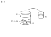
- a solvent introduction step S14 is performed. As shown in FIG. 7, in the solvent introduction step S14, 2-propanol is introduced into a reaction vessel 81 as a solvent 82.
- a catalyst introduction step S15 is performed as shown in Fig. 6. As shown in Fig. 8, in the catalyst introduction step S15, first, stirring of the solvent 82 in the reaction vessel 81 is started. Then, ammonia water is introduced into the reaction vessel 81 as an aqueous solution 83 containing a catalyst.
- the catalyst in this embodiment is a hydroxide ion, which functions as a catalyst for promoting hydrolysis of a metal alkoxide 85 described later.
- a body introduction step S16 is performed. As shown in FIG. 9, in the body introduction step S16, a plurality of body 20 previously formed in the second polishing step S13 as described above is introduced into a reaction vessel 81.
- a polymer introduction step S17 is performed.
- polyvinylpyrrolidone is introduced into the reaction vessel 81 as the polymer 84.
- the polymer 84 introduced into the reaction vessel 81 is adsorbed onto the outer surface 21 of the element body 20.
- a metal alkoxide introduction step S18 is performed.
- liquid tetraethyl orthosilicate is introduced into the reaction vessel 81 as the metal alkoxide 85.
- tetraethyl orthosilicate is also called tetraethoxysilane.
- the amount of metal alkoxide 85 introduced in the metal alkoxide introduction step S18 is calculated based on the area of the outer surface 21 of the element body 20 introduced in the element introduction step S16. Specifically, the amount of metal alkoxide 85 required per element body 20 to form the glass film 50 covering the outer surface 21 of the element body 20 is multiplied by the number of element bodies 20 to calculate the amount.
- a film-forming process S19 is performed.
- the stirring of the solvent 82 that was started in the above-mentioned solvent introduction process S14 is continued for a predetermined time after the metal alkoxide 85 is introduced into the reaction vessel 81 in the metal alkoxide introduction process S18.
- a glass film 50 is formed by a liquid phase reaction in the reaction vessel 81.
- a drying step S20 is performed.
- the element body 20 is removed from the reaction vessel 81 and dried.
- the sol-like glass film 50 is dried to become a gel-like glass film 50.
- the conductor application process S21 is performed.
- conductor paste is applied to two locations on the surface of the glass film 50: a portion including a portion covering the first end face 22A of the element body 20, and a portion including a portion covering the second end face 22B of the element body 20.
- the conductor paste is applied to cover the glass film 50 over the entire first end face 22A and parts of the four side faces 22C.
- the conductor paste is also applied to cover the glass film 50 over the entire second end face 22B and parts of the four side faces 22C.
- the curing step S22 is performed. Specifically, in the curing step S22, the element body 20 to which the glass film 50 and the conductor paste have been applied is heated. This causes the protective film 30 formed on the outer surface 21 of the element body 20 to be baked. Furthermore, as shown in FIG. 3, water and polymer 84 evaporate from the gel-like glass film 50, and the glass film 50 covering the protective film 30 is baked and hardened. Furthermore, in the curing step S22, the conductor paste applied in the conductor application step S21 is baked to form the first base electrode 61A and the second base electrode 62A.
- the Kirkendall effect which arises from the difference in diffusion speed between the first internal electrode 41 and the first base electrode 61A, attracts palladium contained in the first internal electrode 41 to the first base electrode 61A, which contains silver.
- the first penetration portion 71 extends from the first internal electrode 41 toward the first base electrode 61A, penetrating the protective film 30 and the glass film 50, thereby connecting the first internal electrode 41 to the first base electrode 61A.
- the second penetration portion 72 that connects the second internal electrode 42 to the second base electrode 62A.
- the plating process S23 is performed. Electroplating is performed on the first base electrode 61A and the second base electrode 62A. As a result, a first metal layer 61B is formed on the surface of the first base electrode 61A. Also, a second metal layer 62B is formed on the surface of the second base electrode 62A. Although not shown in the figure, the first metal layer 61B and the second metal layer 62B are electroplated with two types of metal, nickel and tin, to form a two-layer structure. In this manner, the electronic component 10 is formed.
- the coefficient of variation of the thickness TP of the protective film 30 is 0.4 or more, so that the thickness TP varies relatively widely. That is, the protective film 30 has numerous irregularities on the outer surface 31. This creates an anchor effect, so that the adhesion of the glass film 50 to the protective film 30 and the adhesion of the first external electrode 61 and the second external electrode 62 to the glass film 50 are high. In this way, if the adhesion of each layer laminated on the outer surface 31 of the protective film 30 is high, it is possible to prevent the plating solution, solder flux, etc. from penetrating through the interface between each layer. Therefore, it is possible to suppress the erosion of the element body 20 by the plating solution, solder flux, etc.
- the outer surface 31 of the protective film 30 has numerous irregularities, the flow of the metal particles in the protective film 30 is suppressed in the hardening step S22.
- the metal particles of the conductive paste are also restrained by the metal particles in the protective film 30, so the fluidity of the metal particles of the conductive paste is suppressed.
- the glass components are restrained in the gaps between the metal particles, so that the glass components are less likely to flow to the outer surface of the molten conductive paste. Therefore, glass is less likely to precipitate on the surface of the external electrode after the conductive paste is fired.
- the average thickness TP of the protective film 30 is 100 nm or less. Because the protective film 30 is formed thin in this manner, it is less likely to impede the formation of the first through-hole 71 and the second through-hole 72 due to the Kirkendall effect. In other words, the connectivity between the first internal electrode 41 and the first external electrode 61 and the connectivity between the second internal electrode 42 and the second external electrode 62 can be ensured.
- the standard deviation of the thickness TP of the protective film 30 is 10 nm or more. If the thickness TP of the protective film 30 varies considerably in this way, the outer surface of the glass film 50 laminated on the outer surface 31 of the protective film 30 will also vary considerably, following the shape of the protective film 30. Therefore, it is easy to obtain the anchor effect of the first external electrode 61 and the second external electrode 62 on the glass film 50.
- the protective film 30 is always present between the edge of the first external electrode 61 and the first through-hole 71, which is the connection portion between the first internal electrode 41 and the first external electrode 61. This blocks the intrusion path of plating solution, flux, etc. that has infiltrated from the edge of the first external electrode 61 to the above-mentioned connection portion. This prevents poor connection between the first external electrode 61 and the first internal electrode 41.
- the second external electrode 62, the second internal electrode 42, and the second through-hole 72 are the same applies to the second external electrode 62, the second internal electrode 42, and the second through-hole 72.
- the glass film 50 is interposed between the protective film 30 and the first and second external electrodes 61 and 62. Therefore, the glass film 50 provides a protective effect not only for the protective film 30 but also for the element body 20. Furthermore, the glass component contained in the conductive paste diffuses into and integrates with the glass film 50, improving the bonding strength between the glass film 50 and the first and second external electrodes 61 and 62. This makes it difficult for each external electrode to peel off from the element body 20.
- the median particle size of the second polishing powder is significantly smaller than that of the first polishing powder.
- a protective film 30 with a large variation in film thickness TP can be formed on the outer surface 21 of the base body 20 without adding a special process for surface roughening.
- the electronic component 10 is not limited to a negative characteristic thermistor component.
- it may be a thermistor component other than a negative characteristic, or it may be a multilayer capacitor component or an inductor component.
- the outer surface 21 of the element body 20 only needs to have a protective film 30 formed thereon, and may not have a boundary surface 23 or a corner surface 24.
- a boundary surface 23 or a corner surface 24 For example, if the boundary between adjacent flat surfaces 22 on the outer surface 21 of the element body 20 is not chamfered, there is no curved surface at the boundary. Therefore, in such a case, the boundary surface 23 and the corner surface 24 may not exist.
- first internal electrode 41 and the second internal electrode 42 are not important as long as it ensures electrical conduction with the corresponding first external electrode 61 and second external electrode 62.
- the number of first internal electrodes 41 and second internal electrodes 42 is not important, and the number of internal electrodes may be one or three or more.
- the configuration of the first external electrode 61 is not limited to the example of the above embodiment.
- the first external electrode 61 may be composed of only the first base electrode 61A, and the first metal layer 61B may not have a two-layer structure. The same applies to the second external electrode 62.
- the combination of materials for the first internal electrode 41 and the first base electrode 61A is not limited to the combination of palladium and silver.
- it may be a combination of copper and nickel, copper and silver, silver and gold, nickel and cobalt, or nickel and gold.
- it may be a combination of one being silver and the other being silver and palladium.
- it may be a combination of one being palladium and the other being silver and palladium, or it may be a combination of one being copper and the other being silver and palladium.
- it may be a combination of one being gold and the other being silver and palladium.
- the Kirkendall effect may not be obtained.
- the first internal electrode 41 may be processed so as to be exposed before the external electrode formation process.
- the first end face 22A side of the element body 20 may be polished to physically remove a part of the protective film 30 and the glass film 50.
- the base electrode formation process may then be performed to connect the first internal electrode 41 and the first base electrode 61A.
- the surface of the first internal electrode 41 exposed from the outer surface 21 of the element body 20 is the connection portion.
- the connection portion is the connection portion.
- the location of the first external electrode 61 is not limited to the example of the above embodiment.
- the first external electrode 61 may be disposed only on the first end surface 22A and one side surface 22C.
- the conductive metals contained in the first base electrode 61A and the second base electrode 62A do not have to be the same.
- the first base electrode 61A may contain Ag
- the second base electrode 62A may contain Cu.
- the protective film 30 does not have to cover the entire outer surface 21 of the element body 20.
- the protective film 30 may cover only the portions of the outer surface 21 of the element body 20 that are covered by the first external electrode 61 and the second external electrode 62, and may not cover the rest of the outer surface 21 of the element body 20.
- only the periphery of the connection portion between the first internal electrode 41 and the first external electrode 61 or the connection portion between the second internal electrode 42 and the second external electrode 62 may be covered by the protective film 30.
- the average value of the thickness TP of the protective film 30 may be greater than 100 nm.
- the first internal electrode 41 and the first external electrode 61 are not connected by the first through-hole 71 formed by the Kirkendall effect, there is little adverse effect even if the average value of the thickness TP is greater than 100 nm.
- the standard deviation of the thickness TP of the protective film 30 may be less than 10 nm. Even if the standard deviation of the thickness TP is 10 nm or more, as long as the coefficient of variation is 0.4 or more, the adhesion of the glass film 50 and each external electrode to the protective film 30 can be ensured.
- the protective film 30 does not necessarily have to be present between the edge of the first external electrode 61 and the first penetration portion 71, which is the connection portion between the first internal electrode 41 and the first external electrode 61.
- a portion of the imaginary line L does not have to overlap with the area where the protective film 30 is present. The same applies to the relationship between the second external electrode 62 and the second penetration portion 72.
- the glass film 50 does not have to cover the entire area of the outer surface 31 of the protective film 30.
- the area covered by the glass film 50 can be changed as appropriate depending on the shape of the element body 20, the positions of the first external electrode 61 and the second external electrode 62, etc.
- the glass in the glass film 50 may diffuse into the glass in the first base electrode 61A, so that the two become integrated.
- the glass film 50 may be omitted. Furthermore, instead of the glass film 50, another film may be formed that is shaped to follow the shape of the outer surface 31 of the protective film 30. In other words, by having irregularities on the outer surface of the film, high adhesion can be obtained due to the anchor effect, and glass precipitation can be suppressed.
- the first base electrode 61A and the second base electrode 62A may be laminated on the outer surface 31 of the protective film 30.
- the first polishing powder and the second polishing powder are preferably alumina, but the composition of each is not important as long as they are aluminum oxide powders with different central particle sizes.
- the first polishing powder and the second polishing powder may be aluminum oxide powders with different compositions.
- the element has an element body, an external electrode covering a part of an outer surface of the element body, and an aluminum oxide protective film, the protective film is located between the element body and the external electrode, a thickness of the protective film in a direction perpendicular to the outer surface of the element body is defined as a film thickness;
- the protective film is viewed in a cross section perpendicular to the outer surface of the element body at a portion covered by the external electrode, the average film thickness and standard deviation are calculated within a range of 1 ⁇ m in a direction along the outer surface of the element body, An electronic component in which the ratio of the standard deviation to the average value is 0.4 or more.
- [4] further comprising an internal electrode located inside the element body, and a connection portion connecting the external electrode and the internal electrode;
- a perpendicular line is drawn from any point on the edge of the external electrode to the outer surface of the element body, and an imaginary line is drawn along the outer surface of the element body connecting the foot of the perpendicular line and any point on the connection portion,
- the electronic component according to any one of [1] to [3], wherein all of the virtual lines overlap with an area where the protective film is present.
- a method for forming a protective film, which is an aluminum oxide film, on an outer surface of an element body comprising the steps of: a laminate preparation step of preparing the element body; a first polishing step of polishing the element body with a first polishing powder which is an aluminum oxide powder; a second polishing step of polishing the element body with a second polishing powder, the second polishing powder being an aluminum oxide powder, after the first polishing step;
- the median particle size which is the most frequent value of the particle size in the particle size distribution, is compared between the first polishing powder and the second polishing powder.
Landscapes
- Engineering & Computer Science (AREA)
- Microelectronics & Electronic Packaging (AREA)
- Power Engineering (AREA)
- Manufacturing & Machinery (AREA)
- Physics & Mathematics (AREA)
- Electromagnetism (AREA)
- Ceramic Engineering (AREA)
- Fixed Capacitors And Capacitor Manufacturing Machines (AREA)
- Thermistors And Varistors (AREA)
- Coils Or Transformers For Communication (AREA)
- Ceramic Capacitors (AREA)
- Formation Of Insulating Films (AREA)
Priority Applications (3)
| Application Number | Priority Date | Filing Date | Title |
|---|---|---|---|
| JP2024519777A JP7529182B1 (ja) | 2022-10-12 | 2023-07-27 | 電子部品及び成膜方法 |
| CN202380072610.XA CN120035869A (zh) | 2022-10-12 | 2023-07-27 | 电子部件以及成膜方法 |
| US19/170,072 US20250232899A1 (en) | 2022-10-12 | 2025-04-04 | Electronic component and film forming method |
Applications Claiming Priority (2)
| Application Number | Priority Date | Filing Date | Title |
|---|---|---|---|
| JP2022163742 | 2022-10-12 | ||
| JP2022-163742 | 2022-10-12 |
Related Child Applications (1)
| Application Number | Title | Priority Date | Filing Date |
|---|---|---|---|
| US19/170,072 Continuation US20250232899A1 (en) | 2022-10-12 | 2025-04-04 | Electronic component and film forming method |
Publications (1)
| Publication Number | Publication Date |
|---|---|
| WO2024079963A1 true WO2024079963A1 (ja) | 2024-04-18 |
Family
ID=90669372
Family Applications (1)
| Application Number | Title | Priority Date | Filing Date |
|---|---|---|---|
| PCT/JP2023/027615 Ceased WO2024079963A1 (ja) | 2022-10-12 | 2023-07-27 | 電子部品及び成膜方法 |
Country Status (4)
| Country | Link |
|---|---|
| US (1) | US20250232899A1 (https=) |
| JP (1) | JP7529182B1 (https=) |
| CN (1) | CN120035869A (https=) |
| WO (1) | WO2024079963A1 (https=) |
Cited By (2)
| Publication number | Priority date | Publication date | Assignee | Title |
|---|---|---|---|---|
| WO2025249191A1 (ja) * | 2024-05-31 | 2025-12-04 | 株式会社村田製作所 | 電子部品 |
| WO2025249192A1 (ja) * | 2024-05-31 | 2025-12-04 | 株式会社村田製作所 | 電子部品 |
Citations (6)
| Publication number | Priority date | Publication date | Assignee | Title |
|---|---|---|---|---|
| JPH01134901A (ja) * | 1987-11-20 | 1989-05-26 | Chichibu Cement Co Ltd | サーミスタ |
| JPH05283206A (ja) * | 1992-03-30 | 1993-10-29 | Taiyo Yuden Co Ltd | チップ型サーミスタの製造方法 |
| JPH0696907A (ja) * | 1992-09-11 | 1994-04-08 | Murata Mfg Co Ltd | チップバリスタの製造方法 |
| JP2007242995A (ja) * | 2006-03-10 | 2007-09-20 | Matsushita Electric Ind Co Ltd | 積層セラミック電子部品とその製造方法 |
| JP2017195309A (ja) * | 2016-04-21 | 2017-10-26 | Tdk株式会社 | 積層コイル部品 |
| JP2021027202A (ja) * | 2019-08-06 | 2021-02-22 | 株式会社村田製作所 | インダクタ |
-
2023
- 2023-07-27 JP JP2024519777A patent/JP7529182B1/ja active Active
- 2023-07-27 CN CN202380072610.XA patent/CN120035869A/zh active Pending
- 2023-07-27 WO PCT/JP2023/027615 patent/WO2024079963A1/ja not_active Ceased
-
2025
- 2025-04-04 US US19/170,072 patent/US20250232899A1/en active Pending
Patent Citations (6)
| Publication number | Priority date | Publication date | Assignee | Title |
|---|---|---|---|---|
| JPH01134901A (ja) * | 1987-11-20 | 1989-05-26 | Chichibu Cement Co Ltd | サーミスタ |
| JPH05283206A (ja) * | 1992-03-30 | 1993-10-29 | Taiyo Yuden Co Ltd | チップ型サーミスタの製造方法 |
| JPH0696907A (ja) * | 1992-09-11 | 1994-04-08 | Murata Mfg Co Ltd | チップバリスタの製造方法 |
| JP2007242995A (ja) * | 2006-03-10 | 2007-09-20 | Matsushita Electric Ind Co Ltd | 積層セラミック電子部品とその製造方法 |
| JP2017195309A (ja) * | 2016-04-21 | 2017-10-26 | Tdk株式会社 | 積層コイル部品 |
| JP2021027202A (ja) * | 2019-08-06 | 2021-02-22 | 株式会社村田製作所 | インダクタ |
Cited By (2)
| Publication number | Priority date | Publication date | Assignee | Title |
|---|---|---|---|---|
| WO2025249191A1 (ja) * | 2024-05-31 | 2025-12-04 | 株式会社村田製作所 | 電子部品 |
| WO2025249192A1 (ja) * | 2024-05-31 | 2025-12-04 | 株式会社村田製作所 | 電子部品 |
Also Published As
| Publication number | Publication date |
|---|---|
| CN120035869A (zh) | 2025-05-23 |
| US20250232899A1 (en) | 2025-07-17 |
| JPWO2024079963A1 (https=) | 2024-04-18 |
| JP7529182B1 (ja) | 2024-08-06 |
Similar Documents
| Publication | Publication Date | Title |
|---|---|---|
| US10714261B2 (en) | Multilayer ceramic capacitor | |
| JP7529182B1 (ja) | 電子部品及び成膜方法 | |
| JP5293506B2 (ja) | セラミック電子部品及びセラミック電子部品の製造方法 | |
| US9275804B2 (en) | Ceramic electronic component and method for producing the same | |
| CN102549687A (zh) | 电容器 | |
| TW201801105A (zh) | 積層線圈零件 | |
| JP2022142213A (ja) | セラミック電子部品、実装基板およびセラミック電子部品の製造方法 | |
| JP7483506B2 (ja) | 電子部品、回路基板および電子部品の製造方法 | |
| WO2006126333A1 (ja) | 積層セラミック電子部品およびその製造方法 | |
| JP2023174139A (ja) | 積層セラミック電子部品およびその製造方法 | |
| KR20130090335A (ko) | 세라믹 전자부품 및 그 제조방법 | |
| JP6788974B2 (ja) | 電子部品 | |
| JP7582508B2 (ja) | 電子部品 | |
| JP7658455B2 (ja) | 電子部品 | |
| WO2024029252A1 (ja) | 電子部品 | |
| JPS61139018A (ja) | チツプ型電子部品の外部接続用電極を形成する方法 | |
| WO2023281838A1 (ja) | 回路基板 | |
| JP2022166463A (ja) | セラミック電子部品および実装基板 | |
| WO2024029251A1 (ja) | 電子部品 | |
| US20250273402A1 (en) | Multilayer electronic component | |
| JP7680252B2 (ja) | 回路基板の製造方法、および、半導体モジュールの製造方法 | |
| US20260011502A1 (en) | Laminated ceramic electronic component | |
| US20250329496A1 (en) | Multilayer ceramic capacitor | |
| WO2025089298A1 (ja) | 電子部品、保護膜の成膜方法、及び電子部品の製造方法 | |
| WO2024236846A1 (ja) | 電子部品、及び成膜方法 |
Legal Events
| Date | Code | Title | Description |
|---|---|---|---|
| ENP | Entry into the national phase |
Ref document number: 2024519777 Country of ref document: JP Kind code of ref document: A |
|
| 121 | Ep: the epo has been informed by wipo that ep was designated in this application |
Ref document number: 23876972 Country of ref document: EP Kind code of ref document: A1 |
|
| WWE | Wipo information: entry into national phase |
Ref document number: 202380072610.X Country of ref document: CN |
|
| NENP | Non-entry into the national phase |
Ref country code: DE |
|
| WWP | Wipo information: published in national office |
Ref document number: 202380072610.X Country of ref document: CN |
|
| 122 | Ep: pct application non-entry in european phase |
Ref document number: 23876972 Country of ref document: EP Kind code of ref document: A1 |