WO2024079884A1 - 車載電力制御システム、制御装置、及び集約制御装置 - Google Patents
車載電力制御システム、制御装置、及び集約制御装置 Download PDFInfo
- Publication number
- WO2024079884A1 WO2024079884A1 PCT/JP2022/038374 JP2022038374W WO2024079884A1 WO 2024079884 A1 WO2024079884 A1 WO 2024079884A1 JP 2022038374 W JP2022038374 W JP 2022038374W WO 2024079884 A1 WO2024079884 A1 WO 2024079884A1
- Authority
- WO
- WIPO (PCT)
- Prior art keywords
- power supply
- control device
- correction
- voltage
- correction request
- Prior art date
- Legal status (The legal status is an assumption and is not a legal conclusion. Google has not performed a legal analysis and makes no representation as to the accuracy of the status listed.)
- Ceased
Links
Images






Classifications
-
- H—ELECTRICITY
- H02—GENERATION; CONVERSION OR DISTRIBUTION OF ELECTRIC POWER
- H02J—ELECTRIC POWER NETWORKS; CIRCUIT ARRANGEMENTS OR SYSTEMS FOR SUPPLYING OR DISTRIBUTING ELECTRIC POWER; SYSTEMS FOR STORING ELECTRIC ENERGY
- H02J1/00—Circuit arrangements for DC mains or DC distribution networks
- H02J1/08—Three-wire DC power distribution systems; Systems having more than three wires
- H02J1/082—DC supplies with two or more different DC voltage levels
-
- B—PERFORMING OPERATIONS; TRANSPORTING
- B60—VEHICLES IN GENERAL
- B60R—VEHICLES, VEHICLE FITTINGS, OR VEHICLE PARTS, NOT OTHERWISE PROVIDED FOR
- B60R16/00—Electric or fluid circuits specially adapted for vehicles and not otherwise provided for; Arrangement of elements of electric or fluid circuits specially adapted for vehicles and not otherwise provided for
- B60R16/02—Electric or fluid circuits specially adapted for vehicles and not otherwise provided for; Arrangement of elements of electric or fluid circuits specially adapted for vehicles and not otherwise provided for electric constitutive elements
- B60R16/03—Electric or fluid circuits specially adapted for vehicles and not otherwise provided for; Arrangement of elements of electric or fluid circuits specially adapted for vehicles and not otherwise provided for electric constitutive elements for supply of electrical power to vehicle subsystems or for
-
- H—ELECTRICITY
- H02—GENERATION; CONVERSION OR DISTRIBUTION OF ELECTRIC POWER
- H02J—ELECTRIC POWER NETWORKS; CIRCUIT ARRANGEMENTS OR SYSTEMS FOR SUPPLYING OR DISTRIBUTING ELECTRIC POWER; SYSTEMS FOR STORING ELECTRIC ENERGY
- H02J7/00—Circuit arrangements for charging or discharging batteries or for supplying loads from batteries
- H02J7/50—Circuit arrangements for charging or discharging batteries or for supplying loads from batteries acting upon multiple batteries simultaneously or sequentially
-
- H—ELECTRICITY
- H02—GENERATION; CONVERSION OR DISTRIBUTION OF ELECTRIC POWER
- H02J—ELECTRIC POWER NETWORKS; CIRCUIT ARRANGEMENTS OR SYSTEMS FOR SUPPLYING OR DISTRIBUTING ELECTRIC POWER; SYSTEMS FOR STORING ELECTRIC ENERGY
- H02J7/00—Circuit arrangements for charging or discharging batteries or for supplying loads from batteries
- H02J7/80—Circuit arrangements for charging or discharging batteries or for supplying loads from batteries including monitoring or indicating arrangements
Definitions
- This disclosure relates to an on-board power control system, and a control device and an aggregated control device mounted in the on-board power control system.
- Patent document 1 describes an overheat protection technology that uses a semiconductor switch and temperature estimation of the wire harness. It states that "The current passing through the wire is detected at predetermined time intervals, and the current wire temperature is estimated using the current passing through the wire, and the current wire temperature is compared with the upper allowable temperature of the wire. Even if the wire temperature rises due to a short circuit current that repeatedly turns on and off, this can be reliably detected and the current passing through the wire can be cut off before the wire reaches a temperature at which it starts to smoke, thereby preventing the wire from starting to smoke.”
- Patent Document 1 when the technology described in Patent Document 1 is used to reduce the diameter of the wires in a wire harness, the wiring resistance value of the wire harness increases, and the amount of voltage drop in the wire harness increases.
- the amount of voltage drop in the wire harness increases as the wire diameter of the wire harness is reduced, causing the power supply voltage supplied to the load to decrease.
- the power supply voltage supplied to the load will fall below the guaranteed operating voltage required to guarantee the performance of the load.
- Patent Document 1 if the technology described in Patent Document 1 is used to reduce the diameter of the wires in the wire harness, the weight of the wires can be reduced, but the performance of the loads such as the control device cannot be guaranteed, which may lead to redesign of the loads and have a significant impact on the vehicle system.
- the present disclosure has been made to solve these technical problems, and aims to suppress the effects of power supply voltage drops caused by the smaller diameter of the wires in the wire harness, and to appropriately ensure the guaranteed operating voltage of the load connected to the wire harness.
- the in-vehicle power control system of the present disclosure includes a power supply device, a control device connected to the power supply device via a first power line, and one or more loads connected to the control device via a second power line.
- the control device has a wiring resistance acquisition means for acquiring wiring resistance values of the first power line and the second power line, a current acquisition means for acquiring a first current value supplied to the control device via the first power line and a second current value supplied to the load via the second power line, a voltage drop amount calculation means for calculating a voltage drop amount in the first power line and the second power line based on the wiring resistance value acquired by the wiring resistance acquisition means, the first current value acquired by the current acquisition means, and the second current value acquired by the current acquisition means, a correction value determination means for determining a correction value for correcting the output voltage of the power supply device based on the voltage drop amount calculated by the voltage drop amount calculation means, and a correction request output means for outputting a correction request indicating the correction value determined by the correction value determination means.
- the control device of the present disclosure is a control device for an in-vehicle power control system connected to a power supply device via a first power line and connected to one or more loads via a second power line, and includes a wiring resistance acquisition means for acquiring a wiring resistance value of the first power line and the second power line, a current acquisition means for acquiring a first current supplied to the control device via the first power line and a second current supplied to the load via the second power line, a voltage drop amount calculation means for calculating a voltage drop amount in the first power line and the second power line based on the wiring resistance value acquired by the wiring resistance acquisition means, the first current acquired by the current acquisition means, and the second current acquired by the current acquisition means, a correction value determination means for determining a correction value for correcting the output voltage of the power supply device based on the voltage drop amount calculated by the voltage drop amount calculation means, and a correction request output means for outputting a correction request indicating the correction value determined by the correction value determination means.
- the aggregated control device of the present disclosure is an aggregated control device that is communicatively connected to the multiple control devices described above, and outputs a correction request selected from the multiple correction requests output from each of the correction request output means of the multiple control devices to a power supply voltage control device that controls the output voltage of the power supply device.
- This disclosure makes it possible to suppress the effects of power supply voltage drops caused by the smaller diameter of the wires in the wire harness, and to appropriately ensure the guaranteed operating voltage of devices connected to the wire harness.
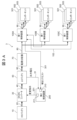
- FIG. 1 is a basic configuration diagram of an in-vehicle power control system 1 according to a first embodiment.
- FIG. 2 is an internal configuration diagram of a first control device 100 according to the first embodiment.
- FIG. 2 is a control flow diagram of the first control device 100 of the first embodiment.
- FIG. 11 is a basic configuration diagram of an on-board power control system 2 according to a second embodiment.
- FIG. 11 is an internal configuration diagram of a third control device 300 according to a second embodiment.
- FIG. 11 is a diagram showing correction requests aggregated by a third control device 300 in the second embodiment.
- FIG. 13 is a diagram showing stored data of a correction request received by a third control device 300 in the second embodiment.
- FIG. 11 is a control flow diagram of a third control device according to the second embodiment.
- FIG. 13 is a basic configuration diagram of an on-board power control system 3 according to a third embodiment.
- FIG. 11 is an internal configuration diagram of a first control device 100A according to a third embodiment.
- FIG. 13 is a basic configuration diagram of an on-board power control system 4 according to a fourth embodiment.
- FIG. 13 is a diagram showing the internal configuration of a semiconductor switch 170 according to a fourth embodiment.
- FIG. 13 is a diagram showing an in-vehicle power control system 4 according to a fourth embodiment when a power line is disconnected.
- FIG. 13 is a diagram showing correction requests aggregated by a third control device 300 in the fifth embodiment.
- FIG. 13 is a control flow diagram of a third control device 300 according to the fifth embodiment.
- FIG. 13 is a time chart showing fluctuations in the output voltage of a DC-DC converter 30 according to a sixth embodiment.
- FIG. 13 is a control flow diagram of a third control device 300 according to the sixth embodiment.
- FIG. 23 is a diagram showing correction requests aggregated by a third control device 300 in the seventh embodiment.
- FIG. 23 is a control flow diagram of a third control device 300 according to the seventh embodiment.
- FIG. 23 is a diagram showing stored data of a correction request received by a third control device 300 in the seventh embodiment.
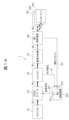
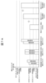
- First Embodiment 1A is a basic configuration diagram of an on-board power control system 1 according to a first embodiment.
- the on-board power control system 1 is an example of a vehicle control system mounted on a vehicle.
- the vehicle-mounted power control system 1 is a system that supplies power supply voltage from a power supply device (high-voltage battery 10 and low-voltage battery 50) to various components 501-503 (loads).
- the components 501-503 are, for example, an ECU (Electronic Control Unit), a sensor, a car navigation system, lamps, and an air conditioner.
- the vehicle-mounted power control system 1 includes a high-voltage battery 10 (HV battery in the figure), a DCDC converter 30, a low-voltage battery 50 (LV battery in the figure), a power distributor 70, a first control device 100, a second control device 200, the components 501-503, and a first power line 20 to a fifth power line 90 that connect them.
- the first power line 20 connects the high-voltage battery 10 and the DCDC converter 30, the second power line 40 connects the DCDC converter 30 and the low-voltage battery 50, the third power line 60 connects the low-voltage battery 50 and the power distributor 70, the fourth power line 80 connects the power distributor 70 and the first control device 100, and the fifth power line 90 connects the first control device 100 and each of the components 501 to 503.
- At least one of the first power line 20 to the fifth power line 90 is a power line of a wire harness having a power line and a signal line.
- the high-voltage battery 10 is the main power source for the vehicle and is a large-capacity battery that is primarily used to drive the vehicle.
- the low-voltage battery 50 (power supply unit) is primarily used as a power supply source for the above-mentioned components 501 to 503 mounted on the vehicle.
- the DCDC converter 30 converts (steps down) the DC voltage supplied from the high-voltage battery 10 to the low-voltage battery 50, and serves to supply power from the high-voltage battery 10 to the low-voltage battery 50. Furthermore, the DCDC converter 30 has the function of changing the output voltage to the low-voltage battery 50. The output voltage of the low-voltage battery 50 depends on the output voltage of the DCDC converter 30.
- the power distributor 70 is disposed between the low-voltage battery 50 and the first control device 100, and is connected to the third power line 60 and the fourth power line 80. In FIG. 1A, the power distributor 70 supplies power to the first control device 100, but it may also distribute power to a load other than the first control device 100.
- the first control device 100 supplies the power supply voltage supplied from the power supply distributor 70 to one or more downstream components 501-503.
- the first control device 100 is connected to the low-voltage battery 50 via a third power supply line 60 and a fourth power supply line 80.
- the multiple components 501-503 are then connected to the first control device 100 via a fifth power supply line 90. Details of the first control device 100 will be described later.
- the second control device 200 monitors the output voltage of the low-voltage battery 50 via signal line 51 and aggregates vehicle information related to power generation from each component 501-503 on the vehicle (for example, the guaranteed operating voltage of each component 501-503).
- the correction request receiving unit 210 of the second control device 200 receives a correction request transmitted from the first control device 100 via signal line 101.
- the correction value indication unit 211 of the second control device 200 instructs the DCDC converter 30 to change the output voltage via signal line 201.
- the second control device 200 instructs the DCDC converter 30 to change the output voltage according to the correction value indicated in the received correction request.
- the first control device 100, the second control device 200, and the DCDC converter 30 are connected to each other via communication protocols used in vehicles, such as CAN (Controller Area Network), LIN (Local Interconnect Network), and Ethernet.
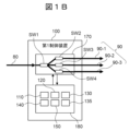
- FIG. 1B is a diagram showing the internal configuration of the first control device 100 of the first embodiment.
- the first control device 100 has a semiconductor switch 170 that supplies or cuts off the power supply voltage to the components 501 to 503, and a microcomputer 180 that controls the semiconductor switch 170.
- the semiconductor switch 170 is composed of, for example, an IPD (Intelligent Power Device) or semiconductor discrete components.
- the semiconductor switch 170 is connected to a fourth power line 80 connected to the power distributor 70 and a fifth power line 90 connected to the components 501 to 503, and supplies and cuts off the power supply voltage.
- the semiconductor switch 170 also measures the current and voltage input to the semiconductor switch 170, and measures the current and voltage output from the semiconductor switch 170.
- the semiconductor switch 170 also has the function of performing fault diagnosis, self-diagnosis, etc.
- the semiconductor switch 170 has a switch SW1 connected to the fourth power line 80, a switch SW2 connected to the power line 90-1 of the fifth power line 90, a switch SW3 connected to the power line 90-2, and a switch SW4 connected to the power line 90-3. These switches SW1 to SW4 are all semiconductor switches such as MOSFETs.
- the semiconductor switch 170 measures the current and voltage supplied to the fourth power line 80.
- the semiconductor switch 170 also measures the current and voltage supplied to each of the power lines 90-1 to 90-3 of the fifth power line 90. The measured current and voltage values are sent to the microcomputer 180.
- the microcomputer 180 is an information processing device having a CPU (Central Processing Unit) and memory, and has functions such as a wiring resistance acquisition unit 110 (wiring resistance acquisition means), a current acquisition unit 120 (current acquisition means), a voltage drop amount calculation unit 130 (voltage drop amount calculation means), a component information unit 135, a correction value determination unit 140 (correction value determination means), and a correction request transmission unit 150 (correction request output means).
- the microcomputer 180 has functions to perform various types of fault diagnoses and self-diagnoses. Each unit will be described later.
- the wiring resistance acquisition unit 110 has information such as the wiring resistance value (reference wiring resistance value) from the low-voltage battery 50 to the components 501 to 503, and the switching resistance value of the semiconductor switch 170. Specifically, the wiring resistance acquisition unit 110 has the wiring resistance value (upstream) from the low-voltage battery 50 to the first control device 100, and the wiring resistance value (downstream) from the first control device 100 to the components 501 to 503.
- the wiring resistance value (upstream) is the combined resistance value of the third power line 60 and the fourth power line 80
- the wiring resistance value (downstream) is the resistance value of each of the power lines 90-1 to 90-3 of the fifth power line 90
- the wiring resistance value is not limited to this and may include, for example, a switching resistance value or a contact resistance value of a connector.
- the information held by the wiring resistance acquisition unit 110 is written in advance to the microcomputer 180 when the first control device 100 is manufactured, or written to the microcomputer 180 after the first control device 100 is mounted on the vehicle. Furthermore, the information held by the wiring resistance acquisition unit 110 may be updated as appropriate.
- the wiring resistance acquisition unit 110 has a function of calculating an estimated temperature value of the wire harness (fourth power line 80, fifth power line 90 (power lines 90-1 to 90-3)) based on the current value and current flow time measured by the semiconductor switch 170 described above, and of adding fluctuations in the wiring resistance value due to the calculated estimated temperature value to the wiring resistance value described above.
- the function of adding fluctuations in the wiring resistance value due to temperature changes is located on the microcomputer 180, but it may be located somewhere other than the microcomputer 180.
- the current acquisition unit 120 acquires each current value measured by the semiconductor switch 170. Specifically, the current acquisition unit 120 acquires the current value (upstream) supplied from the low-voltage battery 50 to the first control device 100, and each current value (downstream) supplied from the first control device 100 to the components 501 to 503.
- the voltage drop calculation unit 130 calculates the voltage drop amount from the low-voltage battery 50 to the components 501 to 503 based on the wiring resistance value (upstream, downstream) acquired from the wiring resistance acquisition unit 110 and the current value (upstream, downstream) acquired from the current acquisition unit 120.
- the component information unit 135 stores information on the guaranteed operating voltages of the components 501 to 503 connected to the first control device 100.
- the information stored in the component information unit 135 is written in advance to the microcomputer 180 when the first control device 100 is manufactured, or written to the microcomputer 180 after the first control device 100 is mounted on the vehicle. Furthermore, the information stored in the component information unit 135 may be updated as appropriate.
- the correction value determination unit 140 calculates a correction value for the power supply voltage based on the voltage drop amount from the low-voltage battery 50 to the components 501 to 503 calculated by the voltage drop amount calculation unit 130 and the guaranteed operating voltage stored in the component information unit 135. Specifically, the correction value determination unit 140 compares the power supply voltage value supplied by the semiconductor switch 170 with the voltage drop amount from the low-voltage battery 50 to the components 501 to 503 calculated by the voltage drop amount calculation unit 130 and the guaranteed operating voltage stored in the component information unit 135, calculates the minimum power supply voltage required for the components 501 to 503, and calculates the correction value for the power supply voltage.
- the correction request sending unit 150 sends a correction request indicating the correction value of the power supply voltage calculated by the correction value determining unit 140 to the second control device 200.
- FIG. 1C is a control flow diagram of the first control device 100 according to the first embodiment. Each step of the flowchart in FIG. 1C is executed by the processor of the microcomputer 180 executing a program expanded in memory. The flowchart shown in FIG. 1C is executed at regular or variable time intervals after the start-up process, initialization process, etc. of the first control device 100 are completed.
- step S110 the microcontroller 180 obtains the reference wiring resistance values (upstream, downstream) that do not take into account temperature changes from the low-voltage battery 50 to the components 501 to 503.
- step S120 the microcontroller 180 acquires the current values (upstream, downstream) and current flow time measured by the semiconductor switch 170.
- step S130 the microcontroller 180 estimates the temperature rise value in the wire harness (third power line 60, fourth power line 80, and fifth power line 90) based on the above-mentioned reference wiring resistance values (upstream, downstream), current values (upstream, downstream), and current flow time.
- step S140 the microcontroller 180 obtains the wiring resistance values (upstream, downstream) associated with the temperature change based on the reference wiring resistance values (upstream, downstream) and the temperature rise value described above.
- step S150 the microcomputer 180 calculates the voltage drop amount (upstream, downstream) from the low-voltage battery 50 to the components 501 to 503 based on the above-mentioned current value (upstream, downstream) and the wiring resistance value (upstream, downstream) associated with temperature change.
- An example of the calculation formula is shown below as formula (1) and formula (2).
- the microcomputer 180 uses the semiconductor switch 170 as a reference, calculates the voltage drop amount (upstream) from the low-voltage battery 50 to the semiconductor switch 170 using formula (1), and calculates each voltage drop amount (downstream) from the semiconductor switch 170 to the components 501 to 503 using formula (2).
- three voltage drop amounts (downstream) are calculated using formula (2), and the largest voltage drop amount is set as the voltage drop amount (downstream).
- Vf_ba current value (upstream) ⁇ wiring resistance value (upstream) (Equation 1)
- Voltage drop amount (downstream) Vf_ac current value (downstream) ⁇ wiring resistance value (downstream) (Equation 2)
- step S160 the microcontroller 180 obtains the power supply voltage that serves as the reference for calculating the correction request.
- step S170 the microcontroller 180 calculates a correction value for the power supply voltage from the reference power supply voltage, the voltage drop amount (upstream), the voltage drop amount (downstream), and the guaranteed operating voltage obtained from the component information unit 135.
- the following formulas (4) and (5) are executed when Vc_Pre ⁇ Vc_lowlimit, and the correction value for the power supply voltage is calculated.
- Vc_pre Va ⁇ Vf_ac Equation (3)
- Vreq Vc_lowlimit-Vc_pre...Equation (4)
- Vreq_total Vf_ba+Vreq+Va (5)
- Va power supply voltage value recognized by the first control device 100
- Vc_pre power supply voltage value in a downstream component calculated by the first control device 100
- Vc_lowlimit lower limit of the guaranteed operating voltage of the components 501 to 503
- Vreq power supply voltage correction relative value required by the components 501 to 503
- Vreq_total correction value of a correction request sent from the first control device 100 to the second control device 200
- step S180 the microcontroller 180 transmits a correction request indicating the correction value of the power supply voltage calculated in step S170 to the correction request receiver 210 of the second control device 200.
- the second control device 200 When the second control device 200 receives a power supply voltage correction request from the microcomputer 180, it sends a change instruction to the DCDC converter 30 to change the output voltage of the DCDC converter 30 in accordance with the correction request.
- the voltage drop amount in the third power line 60, the fourth power line 80, and the fifth power line 90 can be calculated based on the wiring resistance value (upstream, downstream) and the current value (upstream, downstream) from the low-voltage battery 50 to the downstream components 501 to 503. Then, the power supply voltage supplied to the components 501 to 503 calculated from the power supply voltage of the low-voltage battery 50 and the calculated voltage drop amount can be compared in a timely manner with the guaranteed operating voltage value of the downstream components 501 to 503.
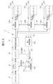
- Figure 2A is a basic configuration diagram of an on-board power control system 2 of the second embodiment.
- the on-board power control system 2 is an example of a vehicle control system to which the present invention is applied. Descriptions of contents that overlap with the first embodiment will be omitted.
- the in-vehicle power control system 2 of this embodiment in a configuration in which multiple first control devices 100A-100C are connected in parallel to one power distributor 70, reduces the complexity of correcting the power supply voltage due to an increase or decrease in the first control devices 100A-100C. This differs from the first embodiment described above in that it takes into consideration correcting the power supply voltage based on correction requests sent from multiple first control devices 100A-100C.
- Each of the multiple first control devices 100A-100C is a zone ECU and is provided for each zone of the vehicle.
- the multiple first control devices 100A-100C are arranged at the front and rear of the vehicle, and inside the vehicle cabin, and each has the role of supplying power supply voltage to components 501-503 arranged near each control device. In FIG. 2A, three first control devices 100A-100C are connected, but the number of first control devices may increase or decrease depending on the vehicle.
- the third control device 300 receives and aggregates the correction requests sent from the multiple first control devices 100A-100C, and transmits them to the second control device 200.
- the third control device 300 aggregate the correction requests, it is possible to appropriately correct the power supply voltage without changing the communication control of the relatively low-functioning second control device 200, even if there are multiple first control devices 100A-100C or the number of connected components 501-503 increases.
- the third control device 300 is an ECU for performing integrated control such as automatic driving of the vehicle, and is connected to the first control devices 100A-100C via CAN or Ethernet communication, and communicates with the third control device 300 using a pre-determined communication format.
- the third control device 300 has a communication circuit so that it can respond to an increase or decrease in the number of connections of the first control devices 100A-100C.
- multiple first control devices 100A-100C are connected from the power distributor 70 via a fourth power line 80.
- Each of the first control devices 100A-100C is connected to one or more components 501-503 via a fifth power line 90.
- each of the first control devices 100A-100C calculates a correction value for the power supply voltage and transmits a correction request to the third control device 300 via a signal line 102.
- the third control device 300 transmits a correction request selected from the multiple correction requests received from the multiple first control devices 100A to 100C to the second control device 200 via the signal line 301.
- the second control device 200 receives the selected correction request, it controls the output voltage of the DCDC converter 30 in accordance with the correction request.
- FIG. 2B is a diagram showing the internal configuration of the third control device 300 of the second embodiment.
- the third control device 300 includes a microcomputer 181.
- the microcomputer 181 includes a correction request receiving unit 305, a correction request aggregating unit 310, and a correction request sending unit 150.
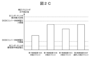
- FIG. 2C is a diagram showing correction requests aggregated by the third control device 300 of the second embodiment.
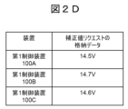
- FIG. 2D is a diagram showing stored data of correction requests received by the third control device 300 of the second embodiment.
- the third control device 300 receives and stores a correction request indicating 14.5V from the first control device 100A, receives and stores a correction request indicating 14.7V from the first control device 100B, and receives and stores a correction request indicating 14.6V from the first control device 100C.
- the third control device 300 selects the correction request with the highest voltage value from among the multiple stored correction requests.
- the third control device 300 selects the correction request (correction value: 14.7 V) received from the first control device 100B.
- the third control device 300 transmits the selected correction request (correction value: 14.7 V) to the second control device 200 via the signal line 301.
- the third control device 300 (warning means) issues a warning as a sign of a malfunction when the correction values indicated by the multiple received correction requests are outside a predetermined range.
- the warning method may include displaying a warning on a display device communicatively connected to the third control device 300, or issuing a warning sound from an audio output device.
- the upper limit of the predetermined range is the minimum value of the absolute maximum ratings of one or more components 501-503, and the lower limit of the predetermined range is the maximum value of the minimum guaranteed operating voltage of one or more components 501-503.
- FIG. 2E is a control flow diagram of the third control device 300 in the second embodiment.
- the flowchart shown in FIG. 2E is executed at regular or variable time intervals after the start-up process and initialization process of the third control device 300 are completed.
- the method for correcting the power supply voltage executed by the first control devices 100A to 100C is the same as in the first embodiment, and therefore will not be described.
- step S200 the microcomputer 181 (correction request receiver 305) of the third control device 300 receives correction requests from the multiple first control devices 100A to 100C.
- step S210 the microcontroller 181 stores the received correction requests in the microcontroller's memory.
- step S220 the microcontroller 181 selects one correction request with the maximum correction value from among the multiple correction requests stored in memory.
- step S230 the microcomputer 181 transmits a correction request in which the selected correction value is the maximum value to the second control device 200.
- the microcomputer 181 since the correction value of the correction request received from the first control device 100B is the maximum value, the microcomputer 181 transmits the correction request received from the first control device 100B to the second control device 200.
- the third control device 300 aggregate correction requests sent from multiple first control devices 100A-100C, even if the number of installed first control devices 100A-100C increases or decreases, there is no need to change the communication protocol between the second control device 200 and the third control device 300, and the second control device 200 shown in the first embodiment can be used as is.
- the third control device 300 can supply to the first control devices 100A-100C a power supply voltage equal to or greater than the correction value of the correction request received from the first control devices 100A-100C.
- the third control device 300 aggregating correction requests, it is possible to shorten the time to determine the power supply voltage to be supplied and the time to supply it.
- Fig. 3A is a basic configuration diagram of an on-board power control system 3 according to the third embodiment.
- the on-board power control system 3 is an example of a vehicle control system to which the present invention is applied. Descriptions of contents that overlap with the above-mentioned embodiments will be omitted.
- the in-vehicle power control system 3 of this embodiment differs from the second embodiment described above in that the correction requests sent by the multiple first control devices 100A to 100C are aggregated by the first control device 100A. Therefore, in this embodiment, the third control device 300 of the second embodiment is not required.
- a correction value is calculated in each of the multiple first control devices 100A to 100C.
- the first control device 100A receives correction requests from the other first control devices 100B and 100C via signal line 102.
- the first control device 100A also selects one correction request from its own correction request and the received correction request, and transmits it to the second control device 200 via signal line 301.
- FIG. 3B is a diagram showing the internal configuration of the first control device 100A of the third embodiment. Compared to the first control device 100 described in FIG. 1B above, it differs in that it has a correction request receiving unit 160 and a correction request aggregating unit 165.
- the correction requests sent by the first control devices 100B and 100C and the correction requests in the own device (first control device 100A) are received by the correction request receiving unit 160 and sent to the correction request aggregating unit 165.
- the correction request aggregating unit 165 selects the correction request with the largest correction value from the multiple correction requests and sends the selected correction request to the correction request sending unit 150.
- the correction request sending unit 150 sends the selected correction request to the second control device 200.
- the on-board power control system 3 of this embodiment it is possible to obtain the same effects as those of the second embodiment described above, even in a system that does not have the third control device 300.
- the device configuration is simplified by the amount that the third control device 300 is not provided, and costs can be reduced.
- Fig. 4A is a basic configuration diagram of an on-board power control system 4 according to the fourth embodiment.
- the on-board power control system 4 is an example of a vehicle control system to which the present invention is applied. Descriptions of contents that overlap with the above-mentioned embodiments will be omitted.
- the power lines of the multiple first control devices 100A to 100C are connected in a ring topology.
- the power distributor 70 and the two first control devices 100A and 100C are connected by a fourth power line 80
- adjacent first control devices 100A and 100B are connected by a sixth power line 81
- adjacent first control devices 100B and 100C are connected by a seventh power line 82.
- the rest of the configuration is the same as in the second embodiment.
- the power supply voltage can be supplied from the power distributor 70 to each of the first control devices 100A to 100C via another power line. As a result, the reliability of the in-vehicle power control system 4 can be improved.
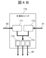
- FIG. 4B is an internal configuration diagram of the semiconductor switch 170 of the fourth embodiment.
- the semiconductor switch 170 of the first control devices 100B and 100C has a similar configuration to the semiconductor switch 170 of the first control device 100A, so a description thereof will be omitted.
- the semiconductor switch 170 includes a semiconductor switch 171 connected to the fourth power line 80, a semiconductor switch 172 connected to the sixth power line 81, and a semiconductor switch group 173 connected to each of the components 501 to 503.
- semiconductor switch 171, semiconductor switch 172, and semiconductor switch group 173 are connected to each other by an internal power supply line 174. Furthermore, the semiconductor switch 171, semiconductor switch 172, and semiconductor switch group 173 are controlled to be turned on and off by a control signal from the microcomputer.
- the semiconductor switch group 173 is connected to the multiple components 501 to 503 via the fifth power line 90.
- the power supply voltage supplied to the semiconductor switch 170 is supplied to the multiple components 501 to 503 via the semiconductor switch group 173.
- FIG. 4C is a diagram showing the on-board power control system 4 of the fourth embodiment when the power line is disconnected.
- the power supply voltage cannot be supplied directly from the power distributor 70 to the first control device 100A. In this case, the power supply voltage cannot be supplied to the components 501 to 503 connected to the first control device 100A.
- first control devices 100A-100C are connected in a ring topology, so that a power supply voltage can be supplied from the power distributor 70 to the first control device 100A via the first power supply voltage supply path (fourth power supply line 80-2, first control device 100C, seventh power supply line 82, first control device 100B, and sixth power supply line 81).
- the power supply voltage is supplied from the power distributor 70 to the first control device 100A via the second power supply voltage supply path (fourth power line 80-1).
- the path of the power supply voltage when the fourth power line 80-1 is not disconnected differs from the path of the power supply voltage when the fourth power line 80-1 is disconnected, so the amount of voltage drop in the path also changes between normal and abnormal conditions. Therefore, when the fourth power line 80-1 is not disconnected, the first control device 100A calculates a correction value taking into account the amount of voltage drop in the third power line 60, the fourth power line 80-1, and the fifth power line 90, and sends a correction request.
- the first control device 100A calculates a correction value taking into account the amount of voltage drop in the third power line 60, the fourth power line 80-2, the seventh power line 82, the sixth power line 81, and the fifth power line 90, and sends a correction request.
- the power supply voltage can be supplied to the first control device 100A and the components 501 to 503 via a bypass power supply line connected by a ring topology.
- the first control device 100A calculates a correction value taking into account the amount of voltage drop and switching resistance in the bypass power supply line and transmits a correction request, thereby obtaining the same effect as that of the first embodiment described above even when the power supply line is broken.
- Figure 5A shows correction requests aggregated by the third control device 300.
- the in-vehicle power control system of this embodiment takes into consideration that when the third control device 300 of the second embodiment described above selects a correction request from among multiple correction requests, it determines whether the correction value indicated by the received correction request is within a predetermined range.
- multiple upper and lower limit values are set for the correction value of the correction request. Since the correction request is used to control the output voltage of the DCDC converter 30, the upper limit value is the maximum output voltage of the DCDC converter 30 or the minimum value of the absolute maximum ratings of the components 501-503 connected to the DCDC converter 30. Here, the maximum output voltage of the DCDC converter 30 is set lower than the minimum value of the absolute maximum ratings of the components 501-503 so as not to exceed the absolute maximum ratings of each of the components 501-503.
- the correction request is used to control the output voltage of the DCDC converter 30, so the lower limit is the minimum output voltage of the DCDC converter 30 or the maximum guaranteed operating voltage of the components 501-503 connected to the DCDC converter 30.
- the minimum output voltage of the DCDC converter 30 is set higher than the maximum guaranteed operating voltage of all the components 501-503, and is not set to fall below the guaranteed operating voltage of all the components 501-503.
- the third control device 300 can determine that a fault has occurred somewhere in the on-board power control system.
- the third control device 300 can determine that the correction value calculated by the first control device 100A-100C is abnormal and that a failure has occurred in the first control device 100A-100C.
- FIG. 5A shows correction requests aggregated by the third control device 300 in the fifth embodiment.
- the third control device 300 receives correction requests indicating correction values within a specified range from the first control device 100A and the first control device 100B.
- the third control device 300 receives a correction request outside the specified range from the first control device 100C.
- the correction value indicated by this correction request is below the maximum guaranteed operating voltage of all components 501-503, and it is found that the correction request indicating the correction value calculated by the first control device 100C is abnormal.
- the third control device 300 functions as a warning means that issues a warning as a precursor to a malfunction if the value indicated by the correction request is outside the specified range.
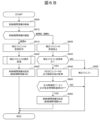
- FIG. 5B is a control flow diagram of the third control device 300 of the fifth embodiment.
- the flowchart shown in FIG. 5B is executed at regular or variable time intervals after the start-up process, initialization process, etc. of the third control device 300 are completed.
- the method of correcting the power supply voltage executed by the first control devices 100A to 100C is the same as in the first embodiment, so a description thereof will be omitted.
- step S500 the third control device 300 stores in memory the correction value indicated by the correction request determined in the previous task.
- a preset setting value is stored.
- step S510 the correction request receiving unit 305 of the third control device 300 receives correction requests sent from the multiple first control devices 100A to 100C.
- step S520 the third control device 300 determines whether the correction value indicated by each correction request received from the first control devices 100A to 100C exceeds the upper limit value. If the correction value indicated by the correction request does not exceed the upper limit value, the process proceeds to step S530, and if the correction value indicated by the correction request exceeds the upper limit value, the process proceeds to step S560.
- step S530 the third control device 300 determines whether the correction value indicated by each correction request received from the first control devices 100A to 100C is below the lower limit. If the correction value indicated by the correction request is not below the lower limit, the process proceeds to step S540; if the correction value indicated by the correction request is below the lower limit, the process proceeds to step S560.
- step S540 is executed when the correction value indicated by the correction request is within a predetermined range. Specifically, in step S540, the third control device 300 selects the correction request with the largest correction value from among the multiple correction requests.
- step S550 the third control device 300 transmits the correction request selected in step S540 to the second control device 200.
- step S560 is executed when the correction value indicated by each correction request is not within the predetermined range.
- the third control device 300 stores state information of the failure state or the pre-failure state in memory.
- Step S570 was normal, meaning that the correction value for the previous task (previous value) was determined as the correction value for the current task.
- Figure 6A is a time chart showing fluctuations in the output voltage of the DC-DC converter 30 of the sixth embodiment.
- the in-vehicle power control system of this embodiment differs from the second embodiment in that when the third control device 300 of the second embodiment aggregates the correction requests transmitted from each of the first control devices 100A to 100C, a period during which the correction requests can be received is set.
- the second control device 200 sends an instruction to change the output voltage to the DCDC converter 30, which then changes the output voltage and settles it to the target power supply voltage.
- the period from when the change instruction is sent to the DCDC converter 30 until the output voltage of the DCDC converter 30 settles is set as a mask period, during which the third control device 300 does not accept correction requests from the first control devices 100A to 100C.
- FIG. 6A shows the period from when a correction request is received until the output voltage of the DCDC converter 30 settles, and the DCDC converter 30 repeats control to change the output voltage according to the change instruction.
- the control period A up to time T100 indicates the period during which the third control device 300 receives multiple correction requests sent from the first control devices 100A to 100C.
- Control period B from time T100 to time T110 indicates a period during which the third control device 300 suspends reception of correction requests sent from the first control devices 100A to 100C. During this control period B, the third control device 300 selects a correction request, sends a correction request to the second control device 200, and the second control device 200 sends a change instruction to the DCDC converter 30.
- Control period C from time T110 to T120 is the period required for the output voltage of the DCDC converter 30 to settle, and indicates the period until the output voltage converges/settles to the final correction value.
- the third control device 300 also suspends reception of correction requests sent from the first control devices 100A to 100C.
- control periods B and C are mask periods.
- FIG. 6B is a control flow diagram of the third control device 300 of the sixth embodiment.
- the flowchart shown in FIG. 6B is executed at regular or variable time intervals after the start-up process, initialization process, etc. of the third control device 300 are completed.
- the method of correcting the power supply voltage executed by the first control devices 100A to 100C is the same as in the first embodiment, so a description thereof will be omitted.
- step S600 the third control device 300 stores control period information in the aggregated control, and proceeds to step S610.
- the control period can be switched between control period A, control period B, and control period C, for example, using a timer function mounted on the microcomputer and a control period determination process described below.
- step S610 the third control device 300 checks the control period information, and if it is control period A, it proceeds to step S615, and if it is control period B or control period C, it proceeds to step S630.
- step S615 the third control device 300 sets permission to receive correction requests and proceeds to step S620.
- step S620 the third control device 300 executes a correction request selection process, for example, executes the correction request aggregation function operation in the second embodiment described above, and proceeds to step S625.
- step S625 the third control device 300 changes the control period information to period B and ends the task processing.
- step S630 the third control device 300 sets the reception of correction requests to be prohibited, and sets the device not to receive correction requests transmitted from the first control devices 100A to 100C. After setting the settings, the process proceeds to step S635.
- step S635 the third control device 300 determines whether a correction request has been sent to the second control device 200. If a correction request has been sent, the third control device 300 proceeds to step S640, and if a correction request has not been sent, the third control device 300 proceeds to step S655.
- step S640 the third control device 300 acquires information on the output control state of the DCDC converter 30.
- the information on the DCDC converter 30 may be transmitted to the third control device 300 via the second control device 200, or may be transmitted directly from the DCDC converter 30 to the third control device 300. Then, the process proceeds to step S645.
- step S645 the third control device 300 checks the output control state of the DCDC converter 30 and checks whether the output control is complete and the output voltage stabilization time has elapsed. If the output control is complete and the output stabilization time has elapsed, the process proceeds to step S650. If the output control is not complete or the output stabilization time has not elapsed, the process does not proceed to step S650 and ends the task processing.
- step S650 the third control device 300 changes the control period information to period A and ends the task processing.
- step S655 the third control device 300 sends a correction request to the second control device 200 and ends the task processing.
- Figure 7A is a diagram showing correction requests aggregated by a third control device 300 in the seventh embodiment.
- the third control device 300 of the second embodiment described above selects a correction request from among multiple correction requests, information on the priority request and general request of the correction request transmitted from the first control devices 100A to 100C is used.
- each component 501-503 is classified into important components (priority loads) that relate to external environment recognition functions related to the vehicle's drive, braking, steering, and automatic driving, and are directly linked to the basic performance of the vehicle, and general components (general loads) that relate to audio and power seat functions, etc.
- important components priority loads
- general components general loads
- the power supply voltage supplied to each component is prioritized for important components.
- the correction requests sent from the first control devices 100A to 100C include high priority correction requests and low priority correction requests.
- the third control device 300 first aggregates the high priority correction requests from the received high priority correction requests and low priority correction requests, selects a correction request from among them, and sends it to the second control device 200. After that, the third control device 300 aggregates the low priority correction requests, selects a correction request from among them, and sends it to the second control device 200.
- a high priority correction request and a low priority correction request are transmitted from each of the three first control devices 100A to 100C.
- STEP 0 indicates the current control voltage of the DCDC converter 30
- STEP 1 indicates the correction value indicated by the high priority correction request which indicates the highest correction value among the high priority correction requests
- STEP 2 indicates the low priority correction request which indicates the highest correction value among the low priority correction requests. Note that if the highest correction value of the low priority correction request is lower than the highest correction value of the high priority correction request, the correction request of STEP 2 is not transmitted.
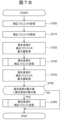
- Figure 7B is a control flow diagram of the third control device 300 of the seventh embodiment.
- the flowchart shown in Figure 7B is executed at regular or variable time intervals after the start-up process and initialization process of the third control device 300 are completed.
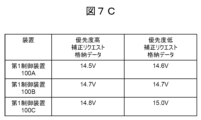
- Figure 7C is a diagram showing stored data of a correction request received by the third control device 300 of the seventh embodiment.
- step S700 the third control device 300 receives multiple correction requests sent from the first control devices 100A to 100C and proceeds to step 710.
- step S710 the third control device 300 stores the received correction requests in memory and proceeds to step S720. As shown in FIG. 7C, the received correction requests are stored in memory.
- step S720 the third control device 300 obtains the maximum value from among the stored high priority correction requests and proceeds to step S730.
- step S730 the third control device 300 transmits the high priority correction request acquired in step S720 to the second control device 200. Then, the process proceeds to step S740.
- step S740 the third control device 300 obtains the maximum value from among the stored correction requests with low priority, and proceeds to step S750.
- step S750 the third control device 300 compares the maximum value of the high priority correction request obtained in step S720 with the maximum value of the low priority correction request obtained in step S740, and if the maximum value of the low priority correction request is greater, it proceeds to step S760, and if the maximum value of the high priority correction request is greater, it ends this task processing without executing step S760.
- step S760 the third control device 300 sends the low priority correction request obtained in step S740 to the second control device 200 and ends this task processing.
- the power supply voltage required by important components directly related to the basic performance of the vehicle can be supplied with priority, thereby making it possible to build a highly safe system that prioritizes the basic performance of the vehicle.
- the present disclosure is not limited to the above-described embodiments, and includes various modified examples.
- the above-described embodiments have been described in detail to clearly explain the present disclosure, and are not necessarily limited to those having all of the configurations described.
- it is possible to replace a part of the configuration of one embodiment with the configuration of another embodiment and it is also possible to add the configuration of another embodiment to the configuration of one embodiment.
- the first control device 100, 100A, 100B, 100C in the above-described embodiments may be a zone ECU provided for each zone of the vehicle, a domain ECU provided for each function of the vehicle, or a central ECU that is communicatively connected to each zone ECU and each domain ECU and controls each zone ECU in an integrated manner.
- Component information unit 140 ...correction value determination unit 150...correction request transmission unit 160...correction request reception unit 165...correction request aggregation unit 170...semiconductor switch 171...semiconductor switch 172...semiconductor switch 173...semiconductor switch group 180...microcomputer 200...second control device 210...correction request reception unit 211...correction value instruction unit 300...third control device 305...correction request reception unit 310...correction request aggregation units 501, 502, 503...components SW1, SW2, SW3, SW4...switch
Landscapes
- Engineering & Computer Science (AREA)
- Power Engineering (AREA)
- Mechanical Engineering (AREA)
- Direct Current Feeding And Distribution (AREA)
- Electric Propulsion And Braking For Vehicles (AREA)
Abstract
Description
以下に説明する発明の構成において、同一部分又は同様な機能を有する部分には同一の符号を異なる図面間で共通して用い、重複する説明は省略することがある。
同一あるいは同様な機能を有する要素が複数ある場合には、同一の符号に異なる添字を付して説明する場合がある。ただし、複数の要素を区別する必要がない場合には、添字を省略して説明する場合がある。
本明細書等における「第1」、「第2」、「第3」などの表記は、構成要素を識別するために付するものであり、必ずしも、数、順序、もしくはその内容を限定するものではない。また、構成要素の識別のための番号は文脈毎に用いられ、一つの文脈で用いた番号が、他の文脈で必ずしも同一の構成を示すとは限らない。また、ある番号で識別された構成要素が、他の番号で識別された構成要素の機能を兼ねることを妨げるものではない。
図面等において示す各構成の位置、大きさ、形状、範囲などは、発明の理解を容易にするため、実際の位置、大きさ、形状、範囲などを表していない場合がある。このため、本発明は、必ずしも、図面等に開示された位置、大きさ、形状、範囲などに限定されない。
本明細書で引用した刊行物、特許および特許出願は、そのまま本明細書の説明の一部を構成する。
本明細書において単数形で表される構成要素は、特段文脈で明らかに示されない限り、複数形を含むものとする。
図1Aは、第1実施形態の車載電力制御システム1の基本構成図である。車載電力制御システム1は、車両に搭載される車両制御システムの一例である。
電圧降下量(下流)Vf_ac=電流値(下流)×配線抵抗値(下流)・・・式(2)
Vreq=Vc_lowlimit-Vc_pre・・・式(4)
Vreq_total=Vf_ba+Vreq+Va・・・式(5)
ここで、式(3)~式(5)の各符号の意味を下記の通りに記載する。
Va:第1制御装置100が認識する電源電圧値
Vc_pre:第1制御装置100が算出する下流のコンポーネントにおける電源電圧値
Vc_lowlimit:コンポーネント501~503の動作保証電圧の下限値
Vreq:コンポーネント501~503が必要とする電源電圧補正相対値
Vreq_total:第1制御装置100から第2制御装置200へ送信する補正リクエストの補正値
本実施形態の車載電力制御システム1によれば、低電圧バッテリ50から下流のコンポーネント501~503までの配線抵抗値(上流、下流)、及び電流値(上流、下流)に基づいて、第3電源線60、第4電源線80、及び第5電源線90における電圧降下量を算出することができる。そして、低電圧バッテリ50の電源電圧及び算出した電圧降下量から算出したコンポーネント501~503に供給される電源電圧と、下流のコンポーネント501~503の動作保証電圧値とをタイムリーに比較することができる。これにより、コンポーネント501~503に供給される電源電圧が、動作保証電圧値よりも低い場合には、低電圧バッテリ50からコンポーネント501~503までの電圧降下量を加味した補正値を算出し、当該補正値を示す補正リクエストをDCDCコンバータ30に送信することができる。その結果、コンポーネント501~503が必要とする動作保証電圧をタイムリーに確保することができる。
以下、図2A~図2Dを参照して第2実施形態を説明する。図2Aは、第2実施形態の車載電力制御システム2の基本構成図である。車載電力制御システム2は、本発明を適用した車両制御システムの一例である。第1実施形態と重複する内容の説明は割愛する。
本実施形態の車載電力制御システム2によれば、複数の第1制御装置100A~100Cが接続されるシステムでも、上述の第1実施形態と同様の作用効果を得ることができる。
以下、図3A及び図3Bを参照して第3実施形態を説明する。図3Aは、第3実施形態の車載電力制御システム3の基本構成図である。車載電力制御システム3は、本発明を適用した車両制御システムの一例である。上述の実施形態と重複する内容の説明は割愛する。
本実施形態の車載電力制御システム3によれば、第3制御装置300を有さないシステムにおいても、上述の第2実施形態と同様の作用効果を得ることができる。第3実施形態では、第2実施形態と比較して、第3制御装置300を有さない分だけ、装置構成が簡素化され、コストダウンを図ることができる。
以下、図4Aから図4Bを参照して第4実施形態を説明する。図4Aは、第4実施形態の車載電力制御システム4の基本構成図である。車載電力制御システム4は、本発明を適用した車両制御システムの一例である。上述の実施形態と重複する内容の説明は割愛する。
第4電源線80-1の断線によって、電源分配器70から第1制御装置100Aへ電源電圧を供給ができない場合であって、リングトポロジにより接続された迂回した電源線を介して、第1制御装置100A及びコンポーネント501~503に電源電圧を供給することができる。この際、第1制御装置100Aは、迂回した電源線での電圧降下量やスイッチング抵抗などを考慮して、補正値を算出し、補正リクエストを送信することによって、電源線の断線時でも、上述の第1実施形態と同様の作用効果を得ることができる。
次に、図5A及び図5Bを参照して第5実施形態を説明する。図5Aは、第3制御装置300が集約した補正リクエストを示す。
上述した方法を用いた第5実施形態によれば、補正リクエストが示す補正値を上下限値と比較することによって、車載電力制御システム内の故障状態又は故障前兆状態をタイムリーに検出することができ、信頼性が向上する。
次に、図6A及び図6Bを参照して第6実施形態を説明する。図6Aは、第6実施形態のDCDCコンバータ30の出力電圧の変動を示すタイムチャートである。
上述した方法を用いた第6実施形態によれば、DCDCコンバータ30が出力電圧の増減を制御している過渡応答期間中に、新たな補正リクエストの受付を中断することができ、DCDCコンバータ30の出力電圧の整定時間を短くでき、安定性を向上させることができる。
次に、図7A~図7Cを参照して第7実施形態を説明する。図7Aは、第7実施形態の第3制御装置300が集約する補正リクエストを示した図である。
第7実施形態では、車両の基本性能に直結する重要なコンポーネントが必要とする電源電圧を優先して供給することができる。これにより、車両の基本性能を優先した安全性の高いシステムを構築することができる。
本開示は、前述した実施形態に限定されるものではなく、様々な変形例が含まれる。例えば、前述した実施形態は本開示を分かりやすく説明するために詳細に説明したものであり、必ずしも説明した全ての構成を備えるものに限定されるものではない。また、ある実施形態の構成の一部を他の実施形態の構成に置き換えることが可能であり、また、ある実施形態の構成に他の実施形態の構成を加えることも可能である。また、各実施形態の構成の一部について、他の構成の追加・削除・置換をすることが可能である。
10…高電圧バッテリ
20…第1電源線
30…DCDCコンバータ
40…第2電源線
50…低電圧バッテリ
51,101,102,201,301…信号線
60…第3電源線
70…電源分配器
80…第4電源線
81…第6電源線
82…第7電源線
90…第5電源線
80-1,80-2,90-1,90-2,90-3…電源線
100,100A,100B,100C…第1制御装置
110…配線抵抗取得部
120…電流取得部
130…電圧降下量算出部
135…コンポーネント情報部
140…補正値決定部
150…補正リクエスト送信部
160…補正リクエスト受信部
165…補正リクエスト集約部
170…半導体スイッチ
171…半導体スイッチ
172…半導体スイッチ
173…半導体スイッチ群
180…マイコン
200…第2制御装置
210…補正リクエスト受信部
211…補正値指示部
300…第3制御装置
305…補正リクエスト受信部
310…補正リクエスト集約部
501,502,503…コンポーネント
SW1,SW2,SW3,SW4…スイッチ
Claims (16)
- 電源装置と、
第1の電源線を介して前記電源装置と接続される制御装置と、
第2の電源線を介して前記制御装置に接続される1又は複数の負荷と、を備え、
前記制御装置は、
前記第1の電源線及び前記第2の電源線の配線抵抗値を取得する配線抵抗取得手段、
前記第1の電源線を介して前記制御装置に供給される第1の電流値および前記第2の電源線を介して前記負荷に供給される第2の電流値を取得する電流取得手段、
前記配線抵抗取得手段によって取得された前記配線抵抗値、前記電流取得手段によって取得された前記第1の電流値、及び前記電流取得手段によって取得された前記第2の電流値に基づいて、前記第1の電源線及び前記第2の電源線での電圧降下量を算出する電圧降下量算出手段、
電圧降下量算出手段によって算出された前記電圧降下量に基づいて、前記電源装置の出力電圧を補正するための補正値を決定する補正値決定手段、及び
前記補正値決定手段によって決定された前記補正値を示す補正リクエストを出力する補正リクエスト出力手段、を有する
ことを特徴とする車載電力制御システム。 - 前記電源装置の出力電圧を制御する電源電圧制御装置をさらに備え、
前記補正リクエスト出力手段は、前記電源電圧制御装置に前記補正リクエストを出力し、
前記電源電圧制御装置は、前記補正リクエストに従って、前記電源装置の出力電圧を制御する
ことを特徴とする請求項1に記載の車載電力制御システム。 - 前記電圧降下量算出手段は、前記第1の電源線又は前記第2の電源線の温度推定値に基づいて、前記電圧降下量を算出する
ことを特徴とする請求項1に記載の車載電力制御システム。 - 前記制御装置は、車両のゾーン毎に複数設けられ、
複数の前記制御装置の各補正リクエスト出力手段は、前記電源装置の出力電圧を補正するための前記補正リクエストを出力する
ことを特徴とする請求項2に記載の車載電力制御システム。 - 複数の前記制御装置の各補正リクエスト出力手段から出力された複数の前記補正リクエストを受信する集約制御装置をさらに備え、
前記集約制御装置は、複数の前記補正リクエストの中から選択した前記補正リクエストを前記電源電圧制御装置に出力し、
前記電源電圧制御装置は、選択された前記補正リクエストに従って、前記電源装置の出力電圧を制御する
ことを特徴とする請求項4に記載の車載電力制御システム。 - 前記集約制御装置は、複数の前記補正リクエストの中から最も高い電圧値を示す前記補正リクエストを選択する
ことを特徴とする請求項5に記載の車載電力制御システム。 - 複数の前記制御装置の中の一の制御装置は、他の1又は複数の制御装置の前記補正リクエスト出力手段から出力された1又は複数の前記補正リクエストを受信し、
前記一の制御装置は、前記一の制御装置の前記補正リクエスト出力手段から出力された前記補正リクエスト、及び前記他の1又は複数の制御装置の前記補正リクエスト出力手段から出力された前記1又は複数の補正リクエストの中から選択した前記補正リクエストを前記電源電圧制御装置に出力し、
前記電源電圧制御装置は、選択された前記補正リクエストに従って、前記電源装置の出力電圧を制御する
ことを特徴とする請求項4に記載の車載電力制御システム。 - 前記一の制御装置は、前記複数の補正リクエストの中から最も高い電圧値を示す前記補正リクエストを選択する
ことを特徴とする請求項7に記載の車載電力制御システム。 - 前記複数の制御装置は、リングトポロジにより接続される
ことを特徴とする請求項4に記載の車載電力制御システム。 - リングトポロジにより接続される前記複数の制御装置は、第1の電源電圧供給経路での電圧降下量に基づいて決定された補正値を示す第1の補正リクエストと、第1の電源電圧供給経路とは異なる第2電源電圧供給経路での電圧降下量に基づいて決定された補正値を示す第2の補正リクエストと、を出力する
ことを特徴とする請求項9に記載の車載電力制御システム。 - 前記補正リクエストが示す値が所定範囲外の場合に故障の前兆として警告を行う警告手段をさらに備える
ことを特徴とする請求項1に記載の車載電力制御システム。 - 前記所定範囲の上限値は、前記1又は複数の負荷の絶対最大定格の最小値であり、前記所定範囲の下限値は、前記1又は複数の負荷の最低動作保証電圧の最大値である
ことを特徴とする請求項11に記載の車載電力制御システム。 - 前記電源電圧制御装置は、前記補正リクエストを受信してから、前記補正リクエストによる前記電源装置の出力電圧が安定するまで、新たな前記補正リクエストをマスクする
ことを特徴とする請求項2に記載の車載電力制御システム。 - 前記負荷は、車両の基本性能に関する優先負荷を含み
前記補正値決定手段は、前記電圧降下量及び前記優先負荷の動作保証電圧に基づいて、前記補正値を決定する
ことを特徴とする請求項1に記載の車載電力制御システム。 - 第1の電源線を介して電源装置と接続され、第2の電源線を介して1又は複数の負荷に接続される車載電力制御システムの制御装置であって、
前記第1の電源線及び前記第2の電源線の配線抵抗値を取得する配線抵抗取得手段と、
前記第1の電源線を介して前記制御装置に供給される第1の電流および前記第2の電源線を介して前記負荷に供給される第2の電流を取得する電流取得手段と、
前記配線抵抗取得手段によって取得された前記配線抵抗値、前記電流取得手段によって取得された前記第1の電流、及び前記電流取得手段によって取得された前記第2の電流に基づいて、前記第1の電源線及び前記第2の電源線での電圧降下量を算出する電圧降下量算出手段と、
電圧降下量算出手段によって算出された前記電圧降下量に基づいて、前記電源装置の出力電圧を補正するための補正値を決定する補正値決定手段と、
前記補正値決定手段によって決定された前記補正値を示す補正リクエストを出力する補正リクエスト出力手段と、を備える
ことを特徴とする制御装置。 - 請求項15に記載の複数の制御装置と通信可能に接続される集約制御装置であって、
前記複数の制御装置の各補正リクエスト出力手段から出力された複数の前記補正リクエストの中から選択した前記補正リクエストを、前記電源装置の出力電圧を制御する電源電圧制御装置に出力する
ことを特徴とする集約制御装置。
Priority Applications (5)
| Application Number | Priority Date | Filing Date | Title |
|---|---|---|---|
| US19/112,719 US12703313B2 (en) | 2022-10-14 | 2022-10-14 | On-vehicle electric power control system, control device, and aggregated control device |
| PCT/JP2022/038374 WO2024079884A1 (ja) | 2022-10-14 | 2022-10-14 | 車載電力制御システム、制御装置、及び集約制御装置 |
| CN202280099793.XA CN119817021A (zh) | 2022-10-14 | 2022-10-14 | 车载电力控制系统、控制装置及汇总控制装置 |
| JP2024551027A JP7905451B2 (ja) | 2022-10-14 | 2022-10-14 | 車載電力制御システム |
| DE112022007476.0T DE112022007476T5 (de) | 2022-10-14 | 2022-10-14 | Steuerungssystem für elektrische leistung im fahrzeug, steuerungseinrichtung und aggregierte steuerungseinrichtung |
Applications Claiming Priority (1)
| Application Number | Priority Date | Filing Date | Title |
|---|---|---|---|
| PCT/JP2022/038374 WO2024079884A1 (ja) | 2022-10-14 | 2022-10-14 | 車載電力制御システム、制御装置、及び集約制御装置 |
Publications (1)
| Publication Number | Publication Date |
|---|---|
| WO2024079884A1 true WO2024079884A1 (ja) | 2024-04-18 |
Family
ID=90669244
Family Applications (1)
| Application Number | Title | Priority Date | Filing Date |
|---|---|---|---|
| PCT/JP2022/038374 Ceased WO2024079884A1 (ja) | 2022-10-14 | 2022-10-14 | 車載電力制御システム、制御装置、及び集約制御装置 |
Country Status (5)
| Country | Link |
|---|---|
| US (1) | US12703313B2 (ja) |
| JP (1) | JP7905451B2 (ja) |
| CN (1) | CN119817021A (ja) |
| DE (1) | DE112022007476T5 (ja) |
| WO (1) | WO2024079884A1 (ja) |
Citations (2)
| Publication number | Priority date | Publication date | Assignee | Title |
|---|---|---|---|---|
| JP2006089014A (ja) * | 2004-08-26 | 2006-04-06 | Auto Network Gijutsu Kenkyusho:Kk | バッテリ状態管理装置及びバッテリ状態管理方法 |
| JP2012039778A (ja) * | 2010-08-09 | 2012-02-23 | Omron Automotive Electronics Co Ltd | Dcdcコンバータ |
Family Cites Families (5)
| Publication number | Priority date | Publication date | Assignee | Title |
|---|---|---|---|---|
| JP4624400B2 (ja) | 2007-11-19 | 2011-02-02 | 株式会社オートネットワーク技術研究所 | 車両用の電線保護方法および電線保護装置 |
| JPWO2012043590A1 (ja) * | 2010-09-30 | 2014-02-24 | 三洋電機株式会社 | 電源装置 |
| JP2015166998A (ja) | 2014-03-04 | 2015-09-24 | 株式会社東芝 | 直流安定化電源装置 |
| JP6908010B2 (ja) | 2018-08-28 | 2021-07-21 | 株式会社デンソー | スイッチの駆動装置 |
| US20250370490A1 (en) * | 2024-05-29 | 2025-12-04 | Panasonic Avionics Corporation | Systems and methods for voltage compensation for seat boxes in transportation vehicles |
-
2022
- 2022-10-14 CN CN202280099793.XA patent/CN119817021A/zh active Pending
- 2022-10-14 WO PCT/JP2022/038374 patent/WO2024079884A1/ja not_active Ceased
- 2022-10-14 JP JP2024551027A patent/JP7905451B2/ja active Active
- 2022-10-14 DE DE112022007476.0T patent/DE112022007476T5/de active Pending
- 2022-10-14 US US19/112,719 patent/US12703313B2/en active Active
Patent Citations (2)
| Publication number | Priority date | Publication date | Assignee | Title |
|---|---|---|---|---|
| JP2006089014A (ja) * | 2004-08-26 | 2006-04-06 | Auto Network Gijutsu Kenkyusho:Kk | バッテリ状態管理装置及びバッテリ状態管理方法 |
| JP2012039778A (ja) * | 2010-08-09 | 2012-02-23 | Omron Automotive Electronics Co Ltd | Dcdcコンバータ |
Also Published As
| Publication number | Publication date |
|---|---|
| JPWO2024079884A1 (ja) | 2024-04-18 |
| US12703313B2 (en) | 2026-08-11 |
| JP7905451B2 (ja) | 2026-08-14 |
| CN119817021A (zh) | 2025-04-11 |
| US20260097728A1 (en) | 2026-04-09 |
| DE112022007476T5 (de) | 2025-05-22 |
Similar Documents
| Publication | Publication Date | Title |
|---|---|---|
| JP7449853B2 (ja) | 車両制御装置 | |
| US11362509B2 (en) | Method of power supply line protection, master device, and power supply system | |
| US9941712B2 (en) | Electrical storage system | |
| CN113492779B (zh) | 用于对车载电网进行配置的方法 | |
| JP6590784B2 (ja) | 内燃機関の始動制御装置 | |
| JP2019041508A (ja) | 電力供給システム | |
| CN114336943A (zh) | 智能驾驶双冗余电源系统 | |
| JP2016060427A (ja) | 車両用電力供給システム | |
| JP3644792B2 (ja) | 車両用電源供給装置 | |
| WO2024084929A1 (ja) | 給電制御装置、給電制御方法及びコンピュータプログラム | |
| CN110034555A (zh) | 冗余电源 | |
| US20180222412A1 (en) | Vehicle power supply control device | |
| JP7211814B2 (ja) | 通電制御方法および電源制御システム | |
| CN118826253A (zh) | 一种冗余供电系统和自动驾驶设备 | |
| US20260097728A1 (en) | On-vehicle electric power control system, control device, and aggregated control device | |
| JP2012201329A (ja) | 車両用電子制御装置及び車両用電子制御システム | |
| US10809291B2 (en) | Method for detecting a proper connection of at least one energy store to an on-board electrical system | |
| JP2005088677A (ja) | 車載用電気応用装置、車載電源制御装置、及び車載電源制御システム | |
| JP6037966B2 (ja) | 車載機器および車輌ヒューズ溶断方法 | |
| JPH1084629A (ja) | 電力分配システム | |
| JP2005263080A (ja) | バッテリ状態検知機能付き車載電源分配装置 | |
| JP2019030163A (ja) | 電力供給装置及び半導体チップ | |
| JP2021158708A (ja) | 電力供給装置及び電力供給システム | |
| JP2008048533A (ja) | 発電機故障検出装置および発電機故障検出方法 | |
| JP7838513B2 (ja) | 車載装置、情報処理方法及びプログラム |
Legal Events
| Date | Code | Title | Description |
|---|---|---|---|
| 121 | Ep: the epo has been informed by wipo that ep was designated in this application |
Ref document number: 22962102 Country of ref document: EP Kind code of ref document: A1 |
|
| WWE | Wipo information: entry into national phase |
Ref document number: 2024551027 Country of ref document: JP |
|
| WWE | Wipo information: entry into national phase |
Ref document number: 112022007476 Country of ref document: DE |
|
| WWE | Wipo information: entry into national phase |
Ref document number: 202280099793.X Country of ref document: CN |
|
| WWP | Wipo information: published in national office |
Ref document number: 202280099793.X Country of ref document: CN |
|
| WWP | Wipo information: published in national office |
Ref document number: 112022007476 Country of ref document: DE |
|
| 122 | Ep: pct application non-entry in european phase |
Ref document number: 22962102 Country of ref document: EP Kind code of ref document: A1 |