WO2024079883A1 - 生産支援装置 - Google Patents
生産支援装置 Download PDFInfo
- Publication number
- WO2024079883A1 WO2024079883A1 PCT/JP2022/038371 JP2022038371W WO2024079883A1 WO 2024079883 A1 WO2024079883 A1 WO 2024079883A1 JP 2022038371 W JP2022038371 W JP 2022038371W WO 2024079883 A1 WO2024079883 A1 WO 2024079883A1
- Authority
- WO
- WIPO (PCT)
- Prior art keywords
- component
- data
- pair
- learning data
- support device
- Prior art date
- Legal status (The legal status is an assumption and is not a legal conclusion. Google has not performed a legal analysis and makes no representation as to the accuracy of the status listed.)
- Ceased
Links
Images




Classifications
-
- H—ELECTRICITY
- H05—ELECTRIC TECHNIQUES NOT OTHERWISE PROVIDED FOR
- H05K—PRINTED CIRCUITS; CASINGS OR CONSTRUCTIONAL DETAILS OF ELECTRIC APPARATUS; MANUFACTURE OF ASSEMBLAGES OF ELECTRICAL COMPONENTS
- H05K13/00—Apparatus or processes specially adapted for manufacturing or adjusting assemblages of electric components
- H05K13/08—Monitoring manufacture of assemblages
- H05K13/085—Production planning, e.g. of allocation of products to machines, of mounting sequences at machine or facility level
-
- G—PHYSICS
- G06—COMPUTING OR CALCULATING; COUNTING
- G06N—COMPUTING ARRANGEMENTS BASED ON SPECIFIC COMPUTATIONAL MODELS
- G06N20/00—Machine learning
-
- G—PHYSICS
- G06—COMPUTING OR CALCULATING; COUNTING
- G06N—COMPUTING ARRANGEMENTS BASED ON SPECIFIC COMPUTATIONAL MODELS
- G06N3/00—Computing arrangements based on biological models
- G06N3/02—Neural networks
- G06N3/04—Architecture, e.g. interconnection topology
-
- G—PHYSICS
- G06—COMPUTING OR CALCULATING; COUNTING
- G06N—COMPUTING ARRANGEMENTS BASED ON SPECIFIC COMPUTATIONAL MODELS
- G06N3/00—Computing arrangements based on biological models
- G06N3/02—Neural networks
- G06N3/08—Learning methods
-
- G—PHYSICS
- G06—COMPUTING OR CALCULATING; COUNTING
- G06N—COMPUTING ARRANGEMENTS BASED ON SPECIFIC COMPUTATIONAL MODELS
- G06N99/00—Subject matter not provided for in other groups of this subclass
Definitions
- This specification relates to a production support device.
- Patent Document 1 a state determination device and a state determination method disclosed in Patent Document 1 (hereinafter referred to as "conventional state determination device, etc.") are known.
- a trained model to which training data classified based on classification conditions is applied is determined, and the classified training data is applied to the determined trained model to perform machine learning.
- machine learning is performed by applying specific classified learning data to a learned model that is selectively determined from a plurality of learned models. Therefore, in conventional state determination devices, etc., the learned model can output the desired inference result for data similar to the specific classified learning data.
- bias occurs in the learning data used for learning, and as a result, a learned model specialized for the classification criteria for classifying the learning data over time is generated.
- the purpose of this specification is to provide a production support device that can use a trained model that is generated while suppressing bias in the training data.
- This specification discloses a production support device that includes a first learning data acquisition unit that acquires multiple first learning data used in first machine learning related to component type pairs that improve the mounting process and obtain a reward by switching component type pairs of components to be mounted on a board between multiple component mounting machines and trying mounting processes, a learning data storage unit that classifies and stores the multiple acquired first learning data according to predetermined classification criteria, an extraction unit that randomly extracts each of the first learning data classified and stored in the learning data storage unit, and a trained model storage unit that stores a trained model generated by performing the first machine learning using the randomly extracted first learning data.
- the production support device randomly extracts each of the classified and stored first learning data and performs first machine learning, thereby making it possible to use a trained model that has been generated while suppressing bias in the learning data.
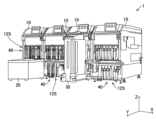
- FIG. 1 is a diagram showing an overall configuration of a production system.
- FIG. 2 is a diagram for explaining a plurality of component mounting machines constituting the production system of FIG. 1 .
- FIG. 3 is a diagram showing a schematic diagram of an overall configuration of the component mounting machine shown in FIG. 2 .
- FIG. 2 is a side view showing a schematic view of a main part of the feeder shown in FIG. 1 .
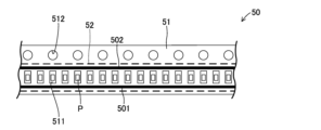
- FIG. 2 is a top view illustrating a carrier tape.
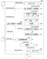
- FIG. 2 is a functional block diagram showing a configuration of a production support device.
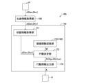
- FIG. 2 is a functional block diagram showing a configuration of an inference phase by a production support device (inference unit).
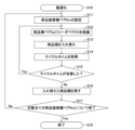
- 4 is a flowchart showing an optimization program executed by the production support device.
- the production support device will be described below with reference to the drawings. In this embodiment, an example will be described in which the production support device is provided in a production system in which a feeder is transported to a component mounting machine by an automatic transport machine.
- the production system 1 includes a plurality of component mounting machines 10 (four in this embodiment) arranged in the width direction, an automatic conveyor 20, a loader device 30, a feeder 40, and a production support device 100.
- the component mounting machine 10 is a substrate-related operation machine that performs a mounting operation of mounting a component P (e.g., an electronic component) on a substrate K as a predetermined operation.
- the board K is transported in sequence into each component mounting machine 10, and a mounting process is performed in which the specified components are mounted in each component mounting machine 10.
- the X-axis direction is the left-right direction (width direction) of the component mounting machine 10
- the Y-axis direction is the front-back direction (depth direction) of the component mounting machine 10
- the Z-axis direction is the up-down direction (vertical direction) of the component mounting machine 10.
- the production system 1 also includes an automatic conveyor 20 that conveys and detaches (replaces) the feeders 40 for each of the component mounting machines 10.
- an example of the automatic conveyor 20 is an AGV (Automatic Guided Vehicle), which is an unmanned transport vehicle (unmanned transport robot) that automatically moves back and forth between an automatic warehouse (not shown) and the component mounting machine 10 to convey a specified feeder 40.
- the automatic conveyor 20 includes a detachment mechanism (e.g., a belt conveyor or an articulated robot) for attaching and detaching the feeder 40 to and from the component supply device 12 of the component mounting machine 10, which will be described later.
- the production system 1 is equipped with a loader device 30 that replenishes parts P and changes the setup for the next production run in accordance with the production schedule.
- the loader device 30 is disposed in front of the component mounting machine 10 (more specifically, the component supply device 12 described below) in the Y-axis direction and is movable in the X-axis direction. Note that in this embodiment, the loader device 30 is also movable in the X-axis direction across adjacent component mounting machines 10 (component supply devices 12).
- the loader device 30 also moves the feeder 40 from the upper level to the lower level or from the lower level to the upper level in the slot 12S of the component supply device 12 described later. Furthermore, the loader device 30 moves and replaces the feeder 40 between two component mounting machines 10, i.e., between the slots 12S of each of the two component supply devices 12. Specifically, the loader device 30 can temporarily store (recover) the feeder 40 set in the upper level of the slot 12S, move it in the X-axis direction, and then discharge the stored (recovered) feeder 40 to the lower level and set it. The loader device 30 can temporarily store (recover) the feeder 40 set in the lower level of the slot 12S, move it in the X-axis direction, and then discharge the stored (recovered) feeder 40 to the upper level and set it.
- the loader device 30 temporarily stores (retrieves) the feeder 40 set in the slot 12S of the component supply device 12 of one component mounting machine 10, moves it in the X-axis direction, and then ejects and sets the stored (retrieved) feeder 40 into the slot 12S of the component supply device 12 of the other component mounting machine 10, i.e., it is possible to interchange multiple feeders 40 between component mounting machines 10. This allows the loader device 30 to automatically supply components P and perform setup changes (including the replacement of feeders 40).
- the production system 1 is provided with a management device H for controlling the entire production.
- the management device H include a host computer or a buffer connected to each of the above-mentioned devices so that they can communicate with each other.
- the management device H supplies various information, including production information J related to production, to each of the above-mentioned devices 10, 20, 30, 40, and 100 as necessary, as described below.
- the component mounting machine 10 mainly comprises a board transport device 11, a component supply device 12, a component transfer device 13, a component camera 14, a board camera 15, and a control device 16.
- the board transport device 11 is composed of a belt conveyor or the like, and transports the board K sequentially in the X-axis direction.
- the board transport device 11 positions the board K at a predetermined position within the component mounting machine 10. Then, when the mounting operation on the positioned board K is completed, the board transport device 11 transports the board K outside the component mounting machine 10 (for example, to an adjacent component mounting machine 10).
- the component supply device 12 supplies components P (e.g., electronic components) to be mounted on the board K.
- the component supply device 12 has a number of slots 12S arranged in the X-axis direction, and a feeder 40 is removably set in each of the slots 12S.
- the slots 12S are formed by an upper section and a lower section along the Z-axis direction (see FIG. 2).
- the component supply device 12 feeds and moves a carrier tape 50 that supplies components P (described later) by the feeder 40, and supplies components P to a component supply position Ps (see FIG. 4) provided at the tip side (upper side in FIG. 3) of the feeder 40.
- the component transfer device 13 holds the component P supplied to the component supply position Ps and mounts the held component P on the positioned board K.
- the component transfer device 13 mainly comprises a head drive device 13A, a moving table 13B, and a mounting head 13C.
- the head drive device 13A moves the moving table 13B in the X-axis and Y-axis directions using a linear motion mechanism.
- the mounting head 13C is a holding device that holds the component P, and is detachably mounted on the moving stage 13B.
- a plurality of suction nozzles 13E capable of holding the component P are detachably mounted on a nozzle holder 13D provided on the mounting head 13C.
- the suction nozzles 13E are supported on the mounting head 13C so that they can rotate about an axis parallel to the Z-axis direction (the up and down direction of the component mounting machine 10) and can be raised and lowered.
- the suction nozzles 13E hold the component P supplied to the component supply position Ps by suction, and mount the held component P on the positioned board K.
- the component camera 14 and the board camera 15 are digital imaging devices having imaging elements such as CCD or CMOS.
- the component camera 14 is fixed to the base of the component mounting machine 10 with its optical axis facing the Z-axis direction, and images the component P held by the suction nozzle 13E from below.
- the board camera 15 is fixed to the moving stage 13B with its optical axis facing the Z-axis direction, and images the board K from above.
- the control device 16 is a computer device whose main components are a CPU, ROM, RAM, and various interfaces, and it controls the overall operation of the component mounting machine 10. Specifically, the control device 16 operates the component mounting machine 10 by executing a control program (not shown). As a result, the component mounting machine 10 performs the mounting work of the component P, for example, according to a sequence stored in advance.
- control device 16 causes the board camera 15 to capture an image of the board K that has been positioned by the board transport device 11. The control device 16 then processes the image captured by the board camera 15 to recognize the positioning state of the board K. The control device 16 also causes the suction nozzle 13E to pick up and hold the component P supplied by the component supply device 12, and causes the component camera 14 to capture an image of the held component P. The control device 16 then processes the image captured by the component camera 14 to recognize the posture of the component P.
- the control device 16 executes a control program and moves the suction nozzle 13E (mounting head 13C) above a designated mounting position that is preset as the position at which the component P is to be mounted on the board K.
- the control device 16 also corrects the designated mounting position and designated mounting angle based on the positioning state of the board K and the attitude of the component P, and sets the mounting position and mounting angle at which the component P is actually mounted.
- the control device 16 corrects the target position (X-axis coordinates and Y-axis coordinates) and rotation angle of the suction nozzle 13E according to the mounting position and mounting angle. The control device 16 then lowers the suction nozzle 13E at the corrected rotation angle in the corrected target position, and mounts the component P on the board K. The control device 16 repeats the pick-and-place cycle as described above to perform the mounting process of mounting multiple components P on the board K.
- Feeder 40 4 the feeder 40 includes a feeder body 41, a drive sprocket 42, a tape pressing unit 43, and a peeling unit 44.
- the feeder 40 holds a reel R on which a carrier tape 50 containing components P for each component type is wound.
- the feeder 40 is capable of communicating with the management device H, for example, when the feeder 40 is set in the slot 12S of the component supply device 12 of the component mounting machine 10 or when the feeder 40 is being transported by the automatic transporter 20.
- the carrier tape 50 wound around the reel R will be described.
- the carrier tape 50 includes a base tape 51 and a cover tape 52.
- the base tape 51 is made of a flexible material such as paper or resin.
- a plurality of cavities 511 capable of accommodating components P are provided at equal intervals along the longitudinal direction of the base tape 51 (the left-right direction in FIG. 5).
- a plurality of feed holes 512 are provided at equal intervals along the longitudinal direction of the base tape 51.
- the plurality of feed holes 512 mesh with the drive sprocket 42.
- the cover tape 52 is formed using a transparent polymer film or the like. As shown by the dashed line in FIG. 5, the cover tape 52 covers the upper surface of the base tape 51 and prevents the component P housed in the cavity 511 from falling out.
- the base tape 51 and the cover tape 52 are joined to each other at joint areas 501 and 502 provided on both sides (one side and the other side) of the width of the carrier tape 50 that sandwich the cavity 511.
- the joint areas 501 and 502 are provided on one side of the width of the carrier tape 50 relative to the feed hole 512.
- the feeder body 41 is a thin box-shaped member formed from a transparent or opaque resin plate or metal plate.
- the side of the feeder body 41 is openable and closable, and inside the feeder body 41, as shown in FIG. 4, a drive sprocket 42, a tape pressing section 43, and a peeling section 44 are arranged.
- the drive sprocket 42 is a sprocket that can mesh with the feed hole 512 provided in the base tape 51 of the carrier tape 50, and is rotatably provided on the feeder body 41.
- a motor e.g., a stepping motor, etc.
- the drive sprocket 42 is driven by the motor and transports the component P to the component supply position Ps by pitch-feeding the carrier tape 50.
- the component supply position Ps is located above the position where the drive sprocket 42 is positioned when viewed from the direction of the rotation axis of the drive sprocket 42 (X-axis direction). This allows the feeder 40 to position the meshing position between the carrier tape 50 and the drive sprocket 42 close to the component supply position Ps, so the feeder 40 can improve the positioning accuracy of the component P transported to the component supply position Ps.
- the tape holding unit 43 guides the carrier tape 50 pulled out from the reel R so that the component P is transported to the component supply position Ps.
- the peeling unit 44 peels the cover tape 52 from the base tape 51 before the component P reaches the component supply position Ps, making the component P accommodated in the cavity 511 available for suction by the suction nozzle 13E (see Figure 3).
- each component mounting machine 10 constituting the production system 1 mounts onto a board K a plurality of different types of components P supplied from each of a plurality of feeders 40 set in a plurality of slots 12S of the component supply device 12 by the automatic conveyor 20 or the loader device 30. That is, each component mounting machine 10 constituting the production system 1 performs a mounting process on the board K by picking and placing the different types of components P in order, and supplies the board K after the mounting process to, for example, an adjacent component mounting machine 10.
- the time required for pick-and-place may differ depending on the type of component P to be mounted on the board K. Therefore, in the production system 1, there may be differences in the cycle time, which represents the time required for each component mounting machine 10 to complete mounting of the component P on the board K. If there is a large difference in cycle time in the production system 1, the component mounting machine 10 requiring a long cycle time may become a so-called bottleneck, and may reduce productivity when producing the board K.
- optimization of the arrangement of components P (component types) mounted on board K by each of the multiple component mounting machines 10 in the production system 1 is considered, i.e., switching between component types of components P in the production system 1 is considered, in order to optimize the mounting order of components P mounted sequentially on board K by the multiple component mounting machines 10 in the production system 1.
- a component type pair Kp representing the component types among all the component types used in the production system 1, or a feeder pair Kf representing the feeders 40 that supply the components P of the component type to be replaced to the component mounting machine 10
- the provisionally determined component type pair Kp or feeder pair Kf
- the mounting process of the components P when the component types (feeders 40) are replaced is simulated, and the cycle time is measured.
- a simulation of the mounting process for the provisionally determined pair of component types Kp (or a pair of feeders Kf) is performed, and the cycle time, which is the result of the simulation, is evaluated, for example, by combining all of the component types (feeders 40) used in the production system 1.
- the production system 1 is equipped with a production support device 100 that infers the above-mentioned component type pair Kp.
- the production support device 100 is provided so as to be able to communicate with each of the component mounting machines 10 (feeders 40), the automatic conveyor 20, the loader device 30, and the management device H that constitute the production system 1.
- the production support device 100 can also be, for example, a device incorporated in the management device H.
- the production support device 100 provides support for maximizing evaluation for a preset evaluation target. An example of the evaluation target is the cycle time.
- the production support device 100 infers and outputs a component type pair Kp to be replaced among the multiple component types of the components P mounted by the component mounting machine 10 according to the evaluation result of the evaluation target.
- the production support device 100 stores a trained model generated by reinforcement learning.
- the production support device 100 uses the trained model and production information J supplied from the management device H to infer and determine a component type pair Kp to be replaced among the multiple component types of the components P used in production, specifically, a feeder pair Kf to be replaced among the multiple feeders 40 set in the component mounting machine 10.
- This allows the production system 1 to optimize the arrangement (replacement) of the component types, that is, the arrangement (replacement) of the feeders 40.
- the cycle time of each component mounting machine 10 is equalized, and the impact of bottlenecks on the overall production in the production system 1 can be reduced.
- the bottleneck for example, if the leveling degree is equal to or above a certain standard, it can be considered that there is no bottleneck.
- the production support device 100 stores each of the first learning data classified according to a predetermined classification criterion.
- the production support device 100 then randomly extracts each of the classified and stored first learning data, and performs first machine learning (reinforcement learning) using the extracted first learning data L1.
- This enables the production support device 100 to reduce (suppress) bias in the first learning data L1 and generate a highly accurate trained model in a short period of time, and ultimately to accurately infer part type pairs Kp with good evaluation results.
- the production support device 100 is a device whose main components are a computer device having a CPU, ROM, RAM, and various interfaces, and as shown in FIG. 6, includes a first learning data acquisition unit 110, a learning data storage unit 120, an extraction unit 130, and a trained model storage unit 150.
- the production support device 100 also includes a production information acquisition unit 160 and an inference unit 170.
- the production support device 100 includes a trained model generation unit 140.
- the production support device 100 also includes an optimizer 180 that can simulate cycle times, which are evaluation results when arbitrarily selected (combined) part type pairs Kp are swapped, and can simulate optimization using the inference results from the inference unit 170.
- an example will be described in which the production support device 100 includes the optimizer 180.
- the optimizer 180 only needs to be able to obtain inference results from the arbitrarily selected part type pairs Kp and the inference unit 170, and can also be provided in a device other than the production support device 100, such as a management device H that can communicate with the production support device 100.
- the first learning data acquisition unit 110 acquires multiple first learning data L1 to be used for first machine learning related to component type pairs Kp, which are represented by component type pair data Cp of multiple components P mounted on a board K by each of multiple component mounting machines 10, and which improve the mounting process and obtain a reward E by trying out the mounting process by swapping the component type pairs Kp represented by the component type pair data Cp of multiple components P mounted on a board K by each of multiple component mounting machines 10.
- the component type pair data Cp representing the component type pair Kp, the feeder pair data Cf representing the feeder pair Kf described below, and the component mounting machine pair data Cm representing the component mounting machine pair Km may be collectively referred to as "pair data C".
- the first learning data L1 acquired by the first learning data acquisition unit 110 may include optimization information D including arrangement data Da relating to the arrangement of the multiple component mounting machines 10 constituting the production system 1 and component type data Dk representing the component types of the multiple components P mounted on the board K by each of the component mounting machines 10.
- the optimization information D includes, for example, as described below, expected cycle time data Ds representing the cycle time when the optimizer 180 simulates the mounting process performed by each component mounting machine 10 for component type pair data Cp of an arbitrarily combined component type pair Kp or inferred component type pair data Cpi representing the component type pair Kp inferred by the inference unit 170.
- the optimization information D also includes replacement restriction information Dj representing the mounting order of the components P that must be strictly observed or whether the components P can be replaced.
- each of the placement data Da, part type data Dk, expected cycle time data Ds, and replacement restriction information Dj included in the optimization information D is supplied from the management device H or an external device not shown.
- the case where the data is supplied from the management device H is illustrated.
- the first learning data acquisition unit 110 acquires, as first learning data L1, the pair data C output from the optimizer 180; specifically, the part type pair data Cp representing any combination of part type pairs Kp, and the cycle time data Rs as result data obtained when simulating the mounting process when the part type pairs Kp represented by the part type pair data Cp are swapped.
- the optimizer 180 links the simulated part type pair data Cp and the cycle time data Rs and outputs them to the first learning data acquisition unit 110.
- the optimizer 180 executes a simulation of the mounting process for the part type pair data Cp of any part type pair Kp that can be determined based on the arrangement data Da and part type data Dk included in the optimization information D, for example, and obtains cycle time data Rs.
- the optimizer 180 also executes a simulation for the part type pair Kp for which the replacement of the part P is not permitted based on the replacement restriction information Dj included in the optimization information D.
- the result data obtained is, for example, a value indicating that the cycle time data Rs indicates that the replacement of the part types is not permitted.
- the first learning data acquisition unit 110 links the acquired optimization information D, pair data C (specifically, part type pair data Cp (or feeder pair data Cf)), and cycle time data Rs to one another.
- the first learning data acquisition unit 110 then outputs the linked optimization information D, pair data C (specifically, part type pair data Cp (or feeder pair data Cf)), and cycle time data Rs to the learning data storage unit 120 as first learning data L1.
- the learning data storage unit 120 classifies and stores the multiple first learning data L1 acquired by the first learning data acquisition unit 110 according to a predetermined classification criterion.
- the result data includes the cycle time data Rs.
- the result data includes cases where the part type pair Kp cannot be replaced.
- the classification criterion is a criterion for classifying the first learning data L1 depending on whether the cycle time represented by the cycle time data Rs has been shortened relative to the expected cycle time represented by the expected cycle time data Ds.
- the classification criterion is a criterion for classifying the first learning data L1 depending on whether the part type can be replaced based on the replacement restriction information Dj.
- the learning data storage unit 120 has multiple (three in this embodiment) storage areas, namely a first memory buffer 121, a second memory buffer 122, and a third memory buffer 123.
- the first memory buffer 121 sequentially accumulates and stores the first learning data L1 in which the cycle time represented by the cycle time data Rs is reduced from the expected cycle time represented by the expected cycle time data Ds, for example, by replacing part types. That is, the first memory buffer 121 sequentially accumulates and stores the first learning data L1 that can be replaced and in which the cycle time is shortened, in other words, the first learning data L1 that appears less frequently.
- the second memory buffer 122 sequentially accumulates and stores the first learning data L1 in which the cycle time represented by the cycle time data Rs has changed from the expected cycle time or has increased from the expected cycle time after part types have been replaced.
- the third memory buffer 123 for example, sequentially accumulates and stores the first learning data L1 in which part types cannot be replaced based on the replacement restriction information Dj. That is, the second memory buffer 122 and the third memory buffer 123 sequentially accumulate and store the first learning data L1 with a high occurrence frequency.
- the extraction unit 130 randomly extracts each of the first learning data L1 classified in the learning data storage unit 120 and stored in the first memory buffer 121, the second memory buffer 122, and the third memory buffer 123.
- first learning data DE1 the first learning data L1 randomly extracted by the extraction unit 130 from the first memory buffer 121
- first learning data DE2 the first learning data L1 randomly extracted by the extraction unit 130 from the second memory buffer 122
- first learning data DE3 the first learning data L1 randomly extracted by the extraction unit 130 from the third memory buffer 123
- first learning data DE3 the first learning data DE3.
- the extraction unit 130 randomly extracts each of the first learning data DE1, the first learning data DE2, and the first learning data DE3 when a certain number or more of the first learning data DE1, the first learning data DE2, and the first learning data DE3 are stored (accumulated) in each of the first memory buffer 121, the second memory buffer 122, and the third memory buffer 123 of the learning data storage unit 120. Furthermore, the extraction unit 130 randomly extracts the first learning data DE1, the first learning data DE2, and the first learning data DE3 stored and classified in the learning data storage unit 120 so as to have an arbitrarily settable composition ratio.
- the composition ratio that can be set arbitrarily can be set according to, for example, the inference accuracy required for inference using the trained model M generated as described below.
- the extraction unit 130 randomly extracts the first learning data DE1, the first learning data DE2, and the first learning data DE3 so that the first learning data DE1 is 40%, the first learning data DE2 is 30%, and the first learning data DE3 is 30%.
- the learning data storage unit 120 accumulates and stores the first learning data L1 so that, for example, 40% is stored in the first memory buffer 121, and 30% is stored in the second memory buffer 122 and the third memory buffer 123.
- the trained model generation unit 140 generates a trained model M by repeatedly performing first machine learning using each of the first training data DE1, the first training data DE2, and the first training data DE3 randomly extracted by the extraction unit 130 so as to have a predetermined composition ratio.
- the multiple components P are each contained in a carrier tape 50 wound around a reel R, and each of the reels R is loaded into a feeder 40 that supplies the components P contained in the carrier tape 50 to the component mounting machine 10.
- the component type pair Kp corresponds to the feeder pair Kf representing the feeders 40 loaded with reels R on which carrier tapes 50 containing the components P of the component types that form the component type pair Kp are wound. Therefore, instead of or in addition to machine learning (reinforcement learning) on the replacement pattern of the component type pair Kp, the trained model generation unit 140 can also generate a trained model M by repeatedly performing machine learning (reinforcement learning) on a replacement pattern in which the feeder pairs Kf are replaced and a reward E, which will be described later, is obtained by multiple component mounting machines 10 mounting the components P. Note that, as the trained model M, the trained model generation unit 140 generates a value function, more specifically, an optimal action value function, as described later.
- the trained model storage unit 150 stores the trained model M generated by the trained model generation unit 140. Therefore, the trained model storage unit 150 can store the trained model M that is updated by the trained model generation unit 140 repeatedly performing machine learning (reinforcement learning).
- the production information acquisition unit 160 acquires production information J that includes at least new placement data Dan and new component type data Dkn, and instructs the component mounting machine 10 to mount new components P to produce a board K. Specifically, the production information acquisition unit 160 acquires production information J from the management device H when the board K is produced, in other words, when optimization of a new component type pair Kp (or a new feeder pair Kf) is required.
- the production information J output by the management device H includes the new number and new arrangement of the component mounting machines 10 constituting the production system 1, which corresponds to the arrangement data Da, the number of feeders 40 set in each component mounting machine 10, the new type and new number of components P to be mounted on each component mounting machine 10, which corresponds to the component type data Dk, and the cycle time as an actual or simulation result, which corresponds to the expected cycle time data Ds.
- the production information J includes control data including the designated mounting position and designated mounting angle of the component P on the board K, component information (shape, dimensions, maximum moving speed, imaging conditions, etc.), the leveling degree of the cycle time (presence or absence of a bottleneck), and equipment information that affects the efficiency of the mounting process (mounting head 13C, suction nozzle 13E, etc.). Therefore, the trained model generation unit 140 can perform machine learning (reinforcement learning) using the production information J as the first training data L1.
- the inference unit 170 uses the new arrangement data Dan and new part type data Dkn included in the production information J acquired by the production information acquisition unit 160 and the learned model M stored in the learned model storage unit 150 to output the inferred inference pair data Ci (specifically, the inferred part type pair data Cpi representing the inferred part type pair Kp or the inferred feeder pair data Cfi representing the inferred feeder pair Kf) that is to be replaced among the new part types distinguished by the part type data Dkn.
- the inferred inference pair data Ci specifically, the inferred part type pair data Cpi representing the inferred part type pair Kp or the inferred feeder pair data Cfi representing the inferred feeder pair Kf
- the inference unit 170 can output the inference pair data Ci (the inferred part type pair data Cpi or the inferred feeder pair data Cfi) to the management device H (more specifically, for example, a display device (not shown) provided in the management device H) to guide the worker or the like.
- the management device H more specifically, for example, a display device (not shown) provided in the management device H
- the inference of the part type pair Kp (or the feeder pair Kf) by the inference unit 170 will be described in detail later.
- trained model generation unit 140 mainly includes state information acquisition unit 141, evaluation result acquisition unit 142, reward calculation unit 143, value function storage unit 144, action decision unit 145, action information output unit 146, and value function update unit 147.
- the state information acquisition unit 141 acquires, as state information, one of the first learning data DE1, the first learning data DE2, and the first learning data DE3 extracted by the extraction unit 130 randomly and to have a predetermined composition ratio. That is, the state information acquisition unit 141 in this embodiment acquires, as state information, one of the first learning data DE1, the first learning data DE2, and the first learning data DE3 that have been classified and randomly extracted to have a predetermined composition ratio.
- the state information acquisition unit 141 mainly acquires state information from the extraction unit 130, but can also acquire state information (first learning data L1) from the optimizer 180.
- the evaluation result acquisition unit 142 acquires, for a preset evaluation target, an evaluation result obtained by a mounting process after replacing a component type pair Kp represented by the component type pair data Cp included in one of the first learning data DE1, the first learning data DE2, and the first learning data DE3, or replacing a feeder pair Kf represented by the feeder pair data Cf among the multiple feeders 40.
- the evaluation result acquisition unit 142 acquires cycle time data Rs, whether the components P are mounted on the board K in ascending order of size, whether the components P are mounted on the board K in ascending order of height from the surface of the board K in the Z-axis direction, and the like. As shown in FIG. 7, the evaluation result acquisition unit 142 can acquire evaluation results for the evaluation target from the optimizer 180.
- the reward calculation unit 143 calculates a reward E for replacing the part type pair Kp (or replacing the feeder pair Kf) in one of the first learning data DE1, the first learning data DE2, and the first learning data DE3 based on the evaluation result (e.g., cycle time data Rs) of the evaluation target obtained by replacing the part type pair Kp represented by the part type pair data Cp (or replacing the feeder pair Kf represented by the feeder pair data Cf). If the evaluation result is good, the reward calculation unit 143 gives a positive reward E for replacing the part type pair Kp (or replacing the feeder pair Kf). On the other hand, if the evaluation result is not good, the reward calculation unit 143 gives a negative reward (penalty) for replacing the part type pair Kp (or replacing the feeder pair Kf).
- the evaluation result e.g., cycle time data Rs
- the remuneration calculation unit 143 simulates the mounting process after switching the component type pair Kp (or switching the feeder pair Kf) with respect to the cycle time, which is one of the evaluation results (or when the mounting process is actually performed by the component mounting machine 10)
- the cycle time represented by the cycle time data Rs decreases
- the remuneration calculation unit 143 gives a positive remuneration E.
- the cycle time represented by the cycle time data Rs increases, the remuneration calculation unit 143 gives a negative remuneration E.
- the remuneration calculation unit 143 simulates the mounting process after switching the component type pair Kp (or switching the feeder pair Kf) with respect to the order in which the components P are placed on the board K, which is one of the evaluation results (or when the mounting process is actually performed by the component mounting machine 10), if the components P are placed (mounted) in order from smallest to largest, or if the components P are placed (mounted) in order from lowest to largest, the remuneration calculation unit 143 gives a positive remuneration E.
- the reward calculation unit 143 gives a negative reward E if the components P are placed (installed) in order from larger to smaller, or if the components P are placed (installed) in order from higher to lower.
- the reward calculation unit 143 calculates the reward E for each evaluation target. Furthermore, the reward calculation unit 143 grants a reward E according to the difference between the evaluation result and the standard set for each evaluation target. That is, when the difference between the evaluation result and the standard is large in the positive direction, the reward calculation unit 143 grants a larger reward E than when the difference between the evaluation result and the standard is small in the positive direction. Conversely, when the difference between the evaluation result and the standard is large in the negative direction, a larger penalty is imposed than when the difference between the evaluation result and the standard is small in the negative direction.
- the cycle time which is one of the evaluation results, will be taken as an example for explanation.
- the cycle time represented by the expected cycle time data Ds included in the optimization information D before the replacement of the part type pair Kp represented by the part type pair data Cp (or the replacement of the feeder pair Kf represented by the feeder pair data Cf) is performed (a simulation is performed) is set as the expected cycle time.
- the reward calculation unit 143 gives a larger reward E than if the shortened time is small in the positive direction. That is, the reward calculation unit 143 gives a larger reward E as the shortened time of the cycle time becomes larger (as the cycle time is shortened). Conversely, if the shortened time is large in the negative direction, that is, if the cycle time is longer than the expected cycle time, the reward calculation unit 143 gives a negative reward E or does not give a reward E.
- the value function memory unit 144 generates a value function in reinforcement learning, i.e., first machine learning, based on the state information acquired by the state information acquisition unit 141 (more specifically, paired data C included in one of the randomly extracted first learning data DE1, first learning data DE2, and first learning data DE3) and the reward E calculated by the reward calculation unit 143.
- the value function is a function generated in order to obtain behavioral information corresponding to the state information so that the evaluation result of the evaluation target is optimized in the learning phase.
- the value function memory unit 144 then stores the generated value function, i.e., the learned model M, in an updatable manner.
- the value function memory unit 144 also performs the function of the learned model memory unit 150.
- the value function (trained model M) of this embodiment is an optimal action value function generated by DQN (Deep Q-Network) as a reinforcement learning algorithm.
- the optimal action value function is found as an approximation function using a neural network, and gives the best action to be taken when a Q value (the value of the reward E obtained instantly according to the state) can be estimated for each action in a certain state.
- the optimal action value function is the trained model M
- the Q value is estimated using a neural network in which the part type pair Kp represented by the part type pair data Cp (or the feeder pair Kf represented by the feeder pair data Cf) becomes a node in the output layer, and as a result, the part type pair Kp represented by the part type pair data Cp (or the feeder pair Kf represented by the feeder pair data Cf) to be replaced as the "best action" is given.
- the value function is not limited to finding the optimal action value function using DQN.
- a "policy" is determined based on the generated value function, and the "best action” is determined based on the "policy.”
- the behavior decision unit 145 determines a part type pair Kp of part types selectable from among a plurality of part types, or a feeder pair Kf selectable from among a plurality of feeders 40, based on the state information (one of the first learning data DE1, the first learning data DE2, and the first learning data DE3 randomly extracted) and the learned model M (optimum action value function). In this case, the behavior decision unit 145 can select the part type pair Kp (or the feeder pair Kf) based on the optimal action value function (learned model M), or search for the part type pair Kp (or the feeder pair Kf) without based on the optimal action value function (learned model M) as necessary. Then, the behavior decision unit 145 outputs part type pair data Cp (or feeder pair data Cf representing the determined feeder pair Kf) representing the determined part type pair Kp, i.e., pair data C.
- the behavior information output unit 146 outputs the contents of the decision made by the behavior decision unit 145, i.e., the part type pair Kp (or feeder pair Kf) to be replaced, to the optimizer 180 as behavior information A.
- the optimizer 180 acquires the behavior information A and performs a simulation of the mounting process based on the virtual mounting conditions in which the part type pair Kp (or feeder pair Kf) is replaced according to the behavior information A. Then, the optimizer 180 estimates the cycle time, which is the evaluation result for the evaluation mode, and outputs cycle time data Rs as the simulation result in the case where the part type pair Kp (or feeder pair Kf) is replaced according to the behavior information A.
- the state information acquisition unit 141 acquires the action information A as new optimization information D, i.e., new state information, for the virtual mounting conditions, and the evaluation result acquisition unit 142 acquires the estimated evaluation result (e.g., cycle time data Rs) of the evaluation target by the optimizer 180.
- the reward calculation unit 143 calculates the reward E for the new optimization information D (i.e., action information A) based on the estimated evaluation result by the optimizer 180.
- the reward calculation unit 143 calculates the evaluation for the action information A that has transitioned from the state information before the replacement of the part type pair Kp (or the feeder pair Kf) (e.g., the expected cycle time data Ds of the optimization information D included in one of the first learning data DE1, DE2, DE3) to the new state information after the replacement of the part type pair Kp (or the feeder pair Kf) (e.g., the cycle time data Rs) as the reward E for the new state information, i.e., the optimization information D.
- the evaluation for the action information A that has transitioned from the state information before the replacement of the part type pair Kp (or the feeder pair Kf) e.g., the expected cycle time data Ds of the optimization information D included in one of the first learning data DE1, DE2, DE3
- the new state information after the replacement of the part type pair Kp (or the feeder pair Kf) e.g., the cycle time data Rs
- the value function update unit 147 updates the optimal action value function stored in the value function update unit 147 based on new state information, i.e., optimization information D (specifically, cycle time data Rs) updated based on the action information A, and the reward E for the new state information (optimization information D reflecting action information A).
- optimization information D specifically, cycle time data Rs
- reward E for the new state information (optimization information D reflecting action information A).
- DQN reinforcement learning algorithm
- inference unit 170 mainly includes state information acquisition unit 171, value function storage unit 172, action decision unit 173, and action information output unit 174.
- state information acquisition unit 171, value function storage unit 172, action decision unit 173, and action information output unit 174 have the same configurations as state information acquisition unit 141, value function storage unit 144, action decision unit 145, and action information output unit 146 of trained model generation unit 140 described above, respectively.
- step S10 the production support device 100's production information acquisition unit 160 acquires production information J that instructs actual production from, for example, the management device H.
- step S11 the production support device 100 (inference unit 170) sets component mounting machine pair data Cm that represents a component mounting machine pair Km of the multiple component mounting machines 10 that constitute the production system 1 based on the production information J.
- the multiple feeders 40 that can be set in each component mounting machine 10 are known, for example, from the optimization information D and production information J.
- the component type of the component P to be mounted in each component mounting machine 10 is also known, for example, from the optimization information D and production information J.
- the relationship between each component type of the component P and each component mounting machine 10 is also known.
- the inference unit 170 when optimizing component types, for example, in accordance with instructions from an operator, the inference unit 170 appropriately sets component mounting machine pair data Cm representing a component mounting machine pair Km among the multiple component mounting machines 10 that make up the production system 1, based on the production information J.
- the production support device 100 infers the component type pair Kp (or feeder pair Kf) using the optimal action value function (trained model M) as a "second step". That is, as shown in FIG. 8, the inference unit 170 acquires production information J including new placement data Dan and component type data Dkn of new component types from the production information acquisition unit 160 by the status information acquisition unit 171 as status information. Then, the action decision unit 173 infers the component type pair Kp (or feeder pair Kf (component mounting machine pair Km)) to be replaced using the status information (production information J) acquired by the status information acquisition unit 171 and the optimal action value function (trained model M) stored in the value function memory unit 172 (trained model memory unit 150).
- the inference unit 170 acquires production information J including new placement data Dan and component type data Dkn of new component types from the production information acquisition unit 160 by the status information acquisition unit 171 as status information.
- the action decision unit 173 infers the component type pair Kp (or feeder pair Kf (component mounting
- the behavior decision unit 173 outputs the inferred component type pair data Cpi representing the inferred component type pair Kp (or the inferred feeder pair data Cfi representing the inferred feeder pair Kf, or the inferred component mounting machine pair data Cmi representing the inferred component mounting machine pair Km), i.e., the inferred pair data Ci, to the behavior information output unit 174.
- the production support device 100 switches the component type pair Kp (or the feeder pair Kf) in the component mounting machine 10. That is, as shown in FIG. 8, the behavior information output unit 174 of the production support device 100 outputs the component type pair Kp (or the feeder pair Kf) inferred in step S11 to the management device H as behavior information A. Then, the management device H outputs a command based on the behavior information A, specifically, a command to switch the feeders 40 that form the feeder pair Kf corresponding to the component type pair Kp, for example, to multiple component mounting machines 10 and loader devices 30.
- each component mounting machine 10 and loader device 30 switches the two feeders 40 identified by the component type pair Kp represented by the component type pair data Cp specified in the behavior information A, specifically, the feeder pair Kf represented by the feeder pair data Cf.
- the switching of the feeders 40 in the component mounting machine 10 includes, for example, changing the identification numbers (numbers corresponding to the order in which the components P are to be mounted) assigned to the slots 12S of the component supply device 12 in response to the switching of the feeders 40.
- the production support device 100 acquires the component type, i.e., the cycle time required for the mounting process after replacing the feeder 40, in the component mounting machine 10. That is, the production support device 100 status information acquisition unit 171 acquires from the management device H the cycle time required for the mounting process in the component mounting machine 10 in which the feeder 40 has been replaced, after the feeder 40 has been replaced.
- the component type i.e., the cycle time required for the mounting process after replacing the feeder 40
- step S15 the production support device 100 judges whether the cycle time acquired in step S14 has improved compared to before the feeder 40 was replaced. That is, if the cycle time after the replacement of the component type pair Kp (or the feeder pair Kf) acquired in step S14 is shorter than the expected cycle time before the replacement of the component type pair Kp (or the feeder pair Kf) included in the production information J (status information) acquired by the production information acquisition unit 160 in step S11, the production support device 100 judges "Yes" since the cycle time has been improved. Then, the production support device 100 returns to step S12 again and executes each step process from step S12 onwards.
- step S12 determines "No" since the cycle time has not been improved. Then, in step S16, the production support device 100 returns the component type replaced in step S13, i.e., the feeder 40, to the state before the replacement, and proceeds to step S17.
- the behavioral information output unit 174 of the production support device 100 outputs, for example, the feeder pair Kf (or component type pair Kp) that returns the corresponding feeder 40 to its pre-swap state as behavioral information A to the management device H.
- the management device H outputs a command based on the behavioral information A, specifically, a command to return the feeders 40 that form the feeder pair Kf corresponding to the component type pair Kp to their pre-swap state, for example, to the multiple component mounting machines 10 and the loader device 30.
- each component mounting machine 10 and loader device 30 returns the component type pair Kp identified in the behavior information A, specifically the two feeders 40 identified by the feeder pair Kf, to the state before the replacement.
- the replacement of the feeders 40 in the component mounting machine 10 includes, for example, changing the identification numbers (numbers corresponding to the order in which the components P are mounted) assigned to the slots 12S of the component supply device 12 in response to the replacement of the feeders 40.
- step S17 the production support device 100 judges whether the above-mentioned component type (feeder 40) replacement, in other words, optimization consideration, has been completed for all of the component mounting machine pairs Km represented by the component mounting machine pair data Cm that can be combined with the multiple component mounting machines 10 that make up the production system 1 based on the production information J. That is, if the optimization consideration for all of the target component mounting machine pairs Km has not been completed, the production support device 100 judges "No" and returns to step S11. Then, when the production support device 100 sets a new component mounting machine pair Km in step S11, it executes each step process from step S12 onwards as described above. On the other hand, if the optimization consideration for all of the target component mounting machine pairs Km has been completed, the production support device 100 judges "Yes" and proceeds to step S18, and ends the execution of the optimization program in step S16.
- the above-mentioned component type (feeder 40) replacement in other words, optimization consideration
- all possible combinations of component mounting machine pairs Km may include, for example, setting combinations of all component mounting machines 10 constituting the production system 1 as component mounting machine pairs Km. Also, for example, if there are combinations of component mounting machines 10 that are expected to have effects such as shortening the cycle time, it is possible to set the component mounting machine pairs Km by selecting the component mounting machines 10 that are likely to have such effects from among all the component mounting machines 10.
- the production support device 100 includes a first learning data acquisition unit 110 that acquires a plurality of first learning data L1 used for the first machine learning related to the component type pair Kp for which the mounting process is improved by switching the component type pair Kp of the components P to be mounted on the board K between the plurality of component mounting machines 10 and performing mounting processes to obtain a reward E; a learning data storage unit 120 that classifies and stores the acquired plurality of first learning data L1 according to a predetermined classification criterion; an extraction unit 130 that randomly extracts each of the first learning data L1 classified and stored in the first memory buffer 121, the second memory buffer 122, and the third memory buffer 123 of the learning data storage unit 120; and a trained model storage unit 150 that stores a trained model M generated by performing the first machine learning using the randomly extracted first learning data L1.
- the production support device 100 also includes a trained model generation unit 140 that generates the trained model M by repeatedly performing the first machine learning using the randomly extracted first learning data L1.
- the production support device 100 further includes a production information acquisition unit 160 that acquires production information J that includes at least arrangement data Da (new arrangement data Dan) representing the arrangement of the component mounting machine 10 and component type data Dk (new component type data Dkn) representing the component type of the component P and instructs the component mounting machine 10 to mount a new component P to produce a board K, and an inference unit 170 that uses the arrangement data Da (new arrangement data Dan) and component type data Dk (new component type data Dkn) of the component P included in the production information J and the trained model M to infer and output a component type pair Kp (inferred component type pair data Cpi representing the inferred component type pair Kp) to be replaced among the new component types distinguished by the component type data Dk (new component type data Dkn).
- a production information acquisition unit 160 that acquires production information J that includes at least arrangement data Da (new arrangement data Dan) representing the arrangement of the component mounting machine 10 and component type data Dk (new component type data Dkn) representing the component type of the component
- the generated trained model M can be used to accurately infer and determine a component type pair Kp (or a feeder pair Kf) that can improve the mounting process between multiple component mounting machines 10.
- the production support device 100 it is not necessary to sequentially consider all combinations of component types (feeders 40) for multiple component types to determine component type pairs Kp (feeder pairs Kf) that are effective for optimization. Furthermore, by using the trained model M, it is possible to selectively determine component type pairs Kp (feeder pairs Kf) that are effective for optimization for new component types as well, and it is possible to efficiently optimize the placement of component types (feeders 40).
- the first learning data L1 classified according to a predetermined classification criterion is stored and accumulated in the first memory buffer 121, the second memory buffer 122, and the third memory buffer 123 of the learning data storage unit 120.
- the first learning data DE1 stored in the first memory buffer 121 specifically, the first learning data L1 including pair data C that allows replacement of the part type pair Kp and reduces the cycle time, requires many trials using the optimizer 180 until a combination is found.
- the first learning data L1 including pair data C that allows replacement of part type pairs Kp and shortens the cycle time appears less frequently, as described above. Therefore, when generating the trained model M, in order to reduce the bias of the first learning data L1 and perform first machine learning (reinforcement learning), it is necessary to accumulate a predetermined number or more of the first learning data DE1 in the first memory buffer 121, which may take time to proceed with the learning.
- a second machine learning is performed using the trained model M generated by the first machine learning, using second learning data L2 including inference pair data Ci inferred by the inference unit 170, to generate a trained model M.
- the part type pair Kp or feeder pair Kf
- the production support device 100 includes a second learning data acquisition unit 190, as indicated by the long dashed line in FIG. 6.
- the second learning data acquisition unit 190 acquires second learning data L2 including the inferred pair data Ci inferred by the inference unit 170, for example, the inferred part type pair data Cpi representing the inferred part type pair Kp.
- the second learning data L2 includes optimization information D and production information J acquired from the management device H, in addition to the inferred part type pair data Cpi.
- the trained model generation unit 140 can perform a first machine learning (reinforcement learning) using the first learning data DE1, the first learning data DE2, and the first learning data DE3 extracted by the extraction unit 130, i.e., the first learning data L1, and can also perform a second machine learning (reinforcement learning) using the second learning data L2 acquired by the second learning data acquisition unit 190.
- the trained model generation unit 140 selects one of the first machine learning and the second machine learning to generate the trained model M.
- the trained model generation unit 140 selects and performs one of the first and second machine learning methods according to the search rate that determines the search ratio according to the epsilon-greedy method, and generates the trained model M. Therefore, as shown in FIG. 7, when the first machine learning is selected according to the epsilon-greedy method, the state information acquisition unit 141 of the first modified example acquires the first learning data L1, i.e., one of the first learning data DE1, the first learning data DE2, and the first learning data DE3, from the extraction unit 130 as state information. On the other hand, when the second machine learning is selected according to the epsilon-greedy method, the state information acquisition unit 141 of the first modified example acquires the second learning data L2 acquired by the second learning data acquisition unit 190 as state information.
- the state information acquisition unit 141 acquires the second learning data L2 from the second learning data acquisition unit 190. Then, as in the above-mentioned embodiment, the value function storage unit 144 generates a value function in reinforcement learning based on the state information acquired by the state information acquisition unit 141 (the second learning data L2, in particular the inference pair data Ci) and the reward E calculated by the reward calculation unit 143.
- the value function storage unit 144 proceeds with reinforcement learning using the inference pair data Ci included in the second learning data L2 for the value function, i.e., the trained model M, generated using the pair data C included in the first learning data DE1 in the above-mentioned embodiment, and stores the trained model M generated by proceeding with the reinforcement learning in an updatable manner.
- the inference pair data Ci (inference component type pair data Cpi (or inference feeder pair data Cfi)) can be used. Therefore, in the first modified example, it is possible to seemingly increase the frequency of reinforcement learning using the first learning data DE1 described in the above embodiment, and to improve the generation speed of the trained model M, in other words, the learning speed.
- the action decision unit 145 can determine a part type pair Kp of part types selectable from among a plurality of part types, or a feeder pair Kf of feeders 40 selectable from among a plurality of feeders 40, based on the state information (second learning data L2) and the learned model M (optimum action value function), as in the above-described embodiment. Note that even in this case, the action decision unit 145 can select the part type pair Kp (or the feeder pair Kf) based on the optimal action value function (learned model M), or search for the part type pair Kp (or the feeder pair Kf) without based on the optimal action value function (learned model M) as necessary.
- the behavior information output unit 146 outputs the contents of the decision made by the behavior decision unit 145, i.e., the component type pair Kp (or the feeder pair Kf) to be replaced, to the optimizer 180 as behavior information A.
- the optimizer 180 acquires the behavior information A, performs a simulation of the mounting process based on the virtual mounting conditions in which the component type pair Kp (or the feeder pair Kf) is replaced according to the behavior information A, estimates the cycle time, which is the evaluation result for the evaluation mode, as the simulation result, and outputs the cycle time data Rs.
- the value function update unit 147 updates the optimal action value function stored in the value function update unit 147 based on new state information, i.e., optimization information D (specifically, cycle time data Rs), updated based on the action information A, and the reward E for the new state information (optimization information D reflecting action information A).
- optimization information D specifically, cycle time data Rs
- the value function update unit 147 only needs to update the optimal action value function based on the reinforcement learning algorithm (DQN), and it is possible not to update the optimal action value function if, for example, a negative reward E is given.
- reinforcement learning can be carried out by using the inferred pair data Ci, i.e., the inferred part type pair data Cpi (or inferred feeder pair data Cfi), inferred using the trained model M as the second learning data L2, in accordance with a judgment according to the situation, particularly for a part type pair Kp (or feeder pair Kf) for which the cycle time represented by the cycle time data Rs can be shortened.
- the inferred pair data Ci i.e., the inferred part type pair data Cpi (or inferred feeder pair data Cfi)
- the trained model M as the second learning data L2
- the inference pair data Ci (inference component type pair data Cpi or inference feeder pair data Cfi) corresponding to the pair data C included in the first learning data DE1 inferred by the trained model M can be used in the second machine learning.
- the frequency of occurrence of the inference pair data Ci in other words, the part type pair Kp (or feeder pair Kf) that can be replaced and that shortens the cycle time, increases.
- the time required to accumulate the first learning data L1 and the second learning data L2, which are classified according to a predetermined classification criterion and stored in the first memory buffer 121, until they reach a predetermined number or more can be shortened.
- the learning time required to generate a trained model M with high inference accuracy can be shortened, and a trained model M can be generated efficiently.
- the same effects as those of the above-mentioned embodiment can be obtained.
- Second Modification for example, a component mounting machine pair Km is set by an operator or the like as the first process, and the production support device 100 is configured to replace, that is, to optimize, the feeders 40 (component types) set in the component mounting machine pair Km selectively set as the second process.
- the number of simulations executed by the optimizer 180 can be reduced, and the arrangement of component types can be efficiently optimized.
- the production support device 100 can infer the component mounting machine pair Km represented by the component mounting machine pair data Cm in the same manner as inferring the component type pair Kp represented by the component type pair data Cp or the feeder pair Kf represented by the feeder pair data Cf, as shown in Figures 6, 7, and 9.
- the component mounting machine pair Km (component mounting machine pair data Cm) is inferred for the component mounting machine 10 on which the feeder 40 (component type) to be replaced is likely to be mounted based on the learned model M and the optimization information D (or production information J).
- the production support device 100 can infer the feeder pair Kf, i.e., the component type pair Kp, that will actually be set on the component mounting machine pair Km in the second process, thereby efficiently optimizing the placement of component types.
- the reward calculation unit 143 calculates the reward E according to the evaluation result regardless of the evaluation target.
- the trained model generation unit 140 may also include a weighting unit 148. The weighting unit 148 will be described below.
- the weighting unit 148 weights the reward E that the reward calculation unit 143 gives to each of the multiple evaluation targets.
- the weighting unit 148 gives a larger reward E or penalty to some of the evaluation targets than to the other evaluation targets. Therefore, the third modified example can also achieve the same effects as the above-mentioned embodiment and first modified example.
- the weighting of the reward E for each evaluation target can be set, for example, by the worker.
- the production support device 100 infers the component type pair Kp (feeder pair Kf) based on the trained model M and the optimization information D (production information J).
- the worker may determine the component type pair Kp and the feeder pair Kf for the limited feeders 40, i.e., the component types, set in the component mounting machines 10 that form the component mounting machine pair Km. Even in this case, since the number of component types (feeders 40) to be replaced is limited, even if the worker determines the component type pair Kp and the feeder pair Kf, it is possible to optimize the arrangement of the component types more efficiently than in the conventional method described above.
- the production support device 100 is provided with a trained model generation unit 140.
- the trained model generation unit 140 can be provided in a device other than the production support device 100 provided in the production system 1 (for example, the management device H of the production system 1, or a computer device that can communicate with the management device H and is owned by the manufacturer that manufactures the production system 1 and the component mounting machine 10, etc.).
- the trained model generation unit 140 provided in a device other than the production support device 100 can generate a trained model M using, for example, optimization information D owned by the manufacturer.
- the generated trained model M is then supplied, for example, to the management device H of the production system 1, and supplied from the management device H to the trained model storage unit 150 of the production support device 100 and stored therein.
- the same effects as those of the above-mentioned embodiment and each modified example can be obtained.
- 1...production system 10...component mounting machine, 11...board transport device, 12...component supply device, 12S...slot, 13...component transfer device, 13A...head drive device, 13B...moving table, 13C...mounting head, 13D...nozzle holder, 13E...suction nozzle, 14...component camera, 15...board camera, 16...control device, 20...automatic transport machine, 30...loader device, 40...feeder, 41...feeder body, 42...drive sprocket, 43...tape pressing section, 44...peeling unit, 50...carrier tape, 501...bonding portion, 502...bonding portion, 51...base tape, 511...cavity, 512...feed hole, 52...cover tape, 100...production support device, 110...first learning data acquisition unit, 120...learning data storage unit, 130...extraction unit, 140...trained model generation unit, 141...state information acquisition unit, 142...evaluation result acquisition unit, 143...reward calculation unit, 144...value function storage unit, 145...action decision
- behavior information output unit 147 ... value function update unit, 148 ... weighting unit, 150 ... learned model storage unit, 160 ... production information acquisition unit, 170 ... inference unit, 171 ... state information acquisition unit, 172 ... value function storage unit, 173 ... behavior decision unit, 174 ... behavior information output unit, 180 ... optimizer, 190 ... second learning data acquisition unit, P ... part, Ps ... part supply position, R ... reel, D ... optimization information, Da ... placement data, Dk ...
- part type data data Ds...estimated cycle time data, Dj...replacement restriction information, C...pair data, Cp...component type pair data, Cf...feeder pair data, Cm...component mounting machine pair data, Ci...inferred pair data, Cpi...inferred component type pair data, Cfi...inferred feeder pair data, Cmi...inferred component mounting machine pair data, Rs...cycle time data (result data), J...production information, M...trained model, E...reward, A...action information, H...management device
Landscapes
- Engineering & Computer Science (AREA)
- Theoretical Computer Science (AREA)
- Physics & Mathematics (AREA)
- Software Systems (AREA)
- Computing Systems (AREA)
- Mathematical Physics (AREA)
- General Physics & Mathematics (AREA)
- General Engineering & Computer Science (AREA)
- Artificial Intelligence (AREA)
- Data Mining & Analysis (AREA)
- Evolutionary Computation (AREA)
- Biophysics (AREA)
- Molecular Biology (AREA)
- General Health & Medical Sciences (AREA)
- Computational Linguistics (AREA)
- Biomedical Technology (AREA)
- Life Sciences & Earth Sciences (AREA)
- Health & Medical Sciences (AREA)
- Computer Vision & Pattern Recognition (AREA)
- Medical Informatics (AREA)
- Operations Research (AREA)
- Manufacturing & Machinery (AREA)
- Microelectronics & Electronic Packaging (AREA)
- Supply And Installment Of Electrical Components (AREA)
Abstract
Description
最初に、図1、図2及び図3を参照して、生産システム1の全体構成を説明する。生産システム1は、幅方向に複数(本実施形態においては、4つ)並べられた部品装着機10と、自動搬送機20と、ローダ装置30と、フィーダ40と、生産支援装置100とを備える。部品装着機10は、所定作業として部品P(例えば、電子部品)を基板Kに装着する装着作業を実施する対基板作業機である。
部品装着機10は、図3にて概略的に示すように、基板搬送装置11と、部品供給装置12と、部品移載装置13と、部品カメラ14と、基板カメラ15と、制御装置16とを主に備える。
フィーダ40は、図4に示すように、フィーダ本体41と、駆動スプロケット42と、テープ押え部43と、剥離部44とを備える。フィーダ40は、部品種ごとに部品Pを収容したキャリアテープ50が巻回されたリールRを保持する。フィーダ40は、例えば、部品装着機10の部品供給装置12のスロット12Sにセットされた状態で、又は、自動搬送機20によって搬送されている状態で、管理装置Hと通信することが可能である。
上述したように、生産システム1を構成する各々の部品装着機10は、自動搬送機20又はローダ装置30によって部品供給装置12の複数のスロット12Sにセットされた複数のフィーダ40の各々から供給される複数の異なる部品種の部品Pを基板Kに装着する。即ち、生産システム1を構成する各々の部品装着機10は、異なる部品種の部品Pを順番にピックアンドプレースすることにより基板Kに装着処理を施し、装着処理を施した基板Kを、例えば、隣接する部品装着機10に供給する。
次に、本実施形態の生産支援装置100の構成を説明する。生産支援装置100は、CPU、ROM、RAM、各種インターフェースを有するコンピュータ装置を主要構成部品とする装置であり、図6に示すように、第一学習用データ取得部110と、学習用データ記憶部120と、抽出部130と、学習済みモデル記憶部150と、を備えている。又、生産支援装置100は、生産情報取得部160と、推論部170とを備えている。更に、生産支援装置100は、学習済みモデル生成部140を備えている。
次に、図7を参照して、学習フェーズにおいて機能する生産支援装置100の学習済みモデル生成部140の構成を説明する。図7に示すように、学習済みモデル生成部140は、状態情報取得部141と、評価結果取得部142と、報酬算出部143と、価値関数記憶部144と、行動決定部145と、行動情報出力部146と、価値関数更新部147とを主に備える。
次に、図8を参照して、推論フェーズにおいて機能する生産支援装置100の推論部170の構成を説明する。図8に示すように、推論部170は、状態情報取得部171と、価値関数記憶部172と、行動決定部173と、行動情報出力部174とを主に備える。尚、状態情報取得部171、価値関数記憶部172、行動決定部173、及び、行動情報出力部174は、それぞれ、上述した学習済みモデル生成部140の状態情報取得部141、価値関数記憶部144、行動決定部145、及び、行動情報出力部146と同等の構成である。
次に、図9に示す最適化プログラムのフローチャートを参照して、生産支援装置100のうち主として推論部170による部品種ペアKp(又はフィーダペアKf)の入れ替えの最適化について説明する。最適化プログラムは、ステップS10に開始される。そして、続くステップS11において、生産支援装置100は、生産情報取得部160が、例えば、管理装置Hから実際の生産を指示する生産情報Jを取得する。そして、生産支援装置100(推論部170)は、「第一工程」として、生産情報Jに基づいて生産システム1を構成する複数の部品装着機10のうちの部品装着機ペアKmを表す部品装着機ペアデータCmを設定する。
上述した実施形態においては、学習用データ記憶部120の第一メモリバッファ121、第二メモリバッファ122及び第三メモリバッファ123には、所定の分類基準に従って分類された第一学習用データL1が記憶されて蓄積される。ところで、特に、第一メモリバッファ121に蓄積される第一学習用データDE1、具体的には、部品種ペアKpの入れ替えが可能であり、且つ、サイクルタイムが短縮されるペアデータCを含む第一学習用データL1は、組み合わせを見つけるまでにオプチマイザ180を用いた多くの試行が必要である。
上述した実施形態においては、例えば、第一工程として作業者等によって部品装着機ペアKmが設定され、生産支援装置100は、第二工程として選択的に設定された部品装着機ペアKmにセットされたフィーダ40(部品種)を入れ替え即ち最適化の対象とすることができるようにした。これにより、上述した実施形態及び第一変形例においては、例えば、オプチマイザ180が実行するシミュレーションの回数を低減することができ、効率良く部品種の配置の最適化を行うことができる。
又、上述した実施形態及び第一変形例においては、学習フェーズにおいて、報酬算出部143は、評価対象に関係なく、評価結果に応じた報酬Eを算出するようにした。これに加えて、図7にて破線により示すように、学習済みモデル生成部140が重み付け部148を備えることも可能である。以下、重み付け部148を説明する。
上述した実施形態及び第一変形例においては、生産支援装置100が学習済みモデルMとオプチマイズ情報D(生産情報J)とに基づいて、部品種ペアKp(フィーダペアKf)を推論するようにした。これに代えて、例えば、第二変形例のように、生産支援装置100によって部品装着機ペアKmが推論される場合には、部品装着機ペアKmを形成する部品装着機10にセットされる限られたフィーダ40即ち部品種について、作業者が部品種ペアKpやフィーダペアKfを決定するようにしても良い。この場合においても、入れ替えの対象となる部品種(フィーダ40)の数が限られるため、仮に作業者が部品種ペアKpやフィーダペアKfを決定したとしても、上述した従来の方法に比べて、効率良く部品種の配置の最適化を図ることが可能となる。
Claims (21)
- 複数の部品装着機の間で基板に装着する部品の部品種ペアを入れ替えて装着処理を試行することにより前記装着処理が改善して報酬が得られる前記部品種ペアに関する第一機械学習に用いられる複数の第一学習用データを取得する第一学習用データ取得部と、
取得された複数の前記第一学習用データを所定の分類基準に従って分類して記憶する学習用データ記憶部と、
前記学習用データ記憶部に分類されて記憶されている各々の前記第一学習用データを無作為に抽出する抽出部と、
無作為に抽出された前記第一学習用データを用いて前記第一機械学習を行うことによって生成された学習済みモデルを記憶する学習済みモデル記憶部と、
を備えた、生産支援装置。 - 前記部品装着機の配置を表す配置データ及び前記部品の部品種を表す部品種データを少なくとも含み、前記部品装着機を用いて新たな前記部品を装着して前記基板を生産することを指示する生産情報を取得する生産情報取得部と、
前記生産情報に含まれる前記配置データ及び前記部品の部品種データと前記学習済みモデルとを用いて、前記部品種データによって区別される新たな前記部品種のうちの入れ替え対象となる前記部品種ペアを推論して出力する推論部と、
を備えた、請求項1に記載の生産支援装置。 - 前記抽出部は、前記学習用データ記憶部において任意に設定可能な構成比となるように分類されて記憶されている各々の前記第一学習用データのうちから無作為に前記第一学習用データを抽出する、請求項1又は2に記載の生産支援装置。
- 前記抽出部は、前記学習用データ記憶部において一定数以上記憶されて蓄積されている各々の前記第一学習用データのうちから無作為に前記第一学習用データを抽出する、請求項1又は2に記載の生産支援装置。
- 無作為に抽出された前記第一学習用データを用いて、前記第一機械学習を繰り返し行うことにより、前記学習済みモデルを生成する学習済みモデル生成部を備えた、請求項1又は2に記載の生産支援装置。
- 前記第一学習用データは、前記学習用データ記憶部において各々の前記第一学習用データが一定数以上記憶されて蓄積された状態で、無作為に抽出される、請求項5に記載の生産支援装置。
- 前記第一学習用データは、
前記部品装着機の配置を表す配置データと、前記部品の部品種を表す部品種データと、前記部品種データによって区別される前記部品種同士の前記部品種ペアを表す部品種ペアデータと、複数の前記部品装着機が前記部品種同士を入れ替えて前記部品を装着する際に得られる結果を表す結果データと、が互いに紐付けされて形成される、請求項1又は2に記載の生産支援装置。 - 前記学習用データ記憶部は、
取得された複数の前記第一学習用データを、前記結果データに関する所定の前記分類基準に従って分類して記憶する、請求項7に記載の生産支援装置。 - 前記結果データは、前記部品の装着に要するサイクルタイムを含んでおり、
前記分類基準は、前記サイクルタイムに応じて前記第一学習用データを分類する基準である、請求項8に記載の生産支援装置。 - 前記結果データは、前記部品種ペアの入れ替えが不能である場合を含んでおり、
前記分類基準は、前記部品種ペアの入れ替えが可能か否かに応じて前記第一学習用データを分類する基準である、請求項8に記載の生産支援装置。 - 更に、前記推論部によって推論された前記部品種ペアを表す推論部品種ペアデータを含む第二学習用データを取得する第二学習用データ取得部を有し、
前記学習済みモデル記憶部は、
前記第一学習用データを用いた前記第一機械学習、及び、前記第二学習用データを用いて推論された前記部品種ペアを入れ替えて前記装着処理を試行することにより前記装着処理が改善して報酬が得られる前記部品種ペアに関する第二機械学習のうちの何れか一方を行うことによって生成された前記学習済みモデルを記憶する、請求項2に記載の生産支援装置。 - 前記第一機械学習、及び、前記第二機械学習のうちの何れか一方を繰り返し行うことにより、前記学習済みモデルを生成する学習済みモデル生成部を備えた、請求項11に記載の生産支援装置。
- 前記学習済みモデル生成部は、
イプシロン-グリーディ法に従い、探索割合を決定する探索率に応じて前記第一機械学習及び前記第二機械学習の一方を選択して行い、前記学習済みモデルを生成する、請求項12に記載の生産支援装置。 - 前記報酬は、
前記部品種ペアの入れ替えを行った後のシミュレーションにおいて、前記部品の装着に要するサイクルタイムが短縮される場合に与えられる、請求項1又は2に記載の生産支援装置。 - 前記報酬は、
前記部品種ペアの入れ替えを行う前の前記サイクルタイムに比べて、前記部品種ペアの入れ替えを行った後の前記サイクルタイムの短縮時間が大きくなるにつれて大きくなる、請求項14に記載の生産支援装置。 - 前記報酬は、
前記部品種ペアの入れ替えを行った後のシミュレーションにおいて、前記部品が小さい順に前記基板に装着される場合に与えられる、請求項1又は2に記載の生産支援装置。 - 前記報酬は、
前記部品種ペアの入れ替えを行った後のシミュレーションにおいて、前記部品の前記基板の表面からの高さが低い順に前記基板に装着される場合に与えられる、請求項16に記載の生産支援装置。 - 複数の前記部品は、各々、リールに巻回されたキャリアテープに収容されており、
前記リールは、各々、前記キャリアテープに収容された前記部品を前記部品装着機に供給するフィーダに装填される、請求項2に記載の生産支援装置。 - 前記推論部は、
前記部品を前記部品装着機に供給する前記フィーダ同士を表すフィーダペアを前記部品種ペアとして推論して出力する、請求項18に記載の生産支援装置。 - 前記配置データに基づいて複数の前記部品装着機のうちの前記部品装着機同士を表す部品装着機ペアを設定する第一工程と、
前記部品装着機ペアにおける前記部品種ペアを推論して出力する第二工程と、を実行する、請求項2に記載の生産支援装置。 - 前記推論部は、
前記生産情報と前記学習済みモデルとを用いて、前記第一工程における前記部品装着機ペアを推論して出力する、請求項20に記載の生産支援装置。
Priority Applications (3)
| Application Number | Priority Date | Filing Date | Title |
|---|---|---|---|
| JP2024551026A JPWO2024079883A1 (ja) | 2022-10-14 | 2022-10-14 | |
| DE112022007902.9T DE112022007902T5 (de) | 2022-10-14 | 2022-10-14 | Produktionsunterstützungsvorrichtung |
| PCT/JP2022/038371 WO2024079883A1 (ja) | 2022-10-14 | 2022-10-14 | 生産支援装置 |
Applications Claiming Priority (1)
| Application Number | Priority Date | Filing Date | Title |
|---|---|---|---|
| PCT/JP2022/038371 WO2024079883A1 (ja) | 2022-10-14 | 2022-10-14 | 生産支援装置 |
Publications (1)
| Publication Number | Publication Date |
|---|---|
| WO2024079883A1 true WO2024079883A1 (ja) | 2024-04-18 |
Family
ID=90669247
Family Applications (1)
| Application Number | Title | Priority Date | Filing Date |
|---|---|---|---|
| PCT/JP2022/038371 Ceased WO2024079883A1 (ja) | 2022-10-14 | 2022-10-14 | 生産支援装置 |
Country Status (3)
| Country | Link |
|---|---|
| JP (1) | JPWO2024079883A1 (ja) |
| DE (1) | DE112022007902T5 (ja) |
| WO (1) | WO2024079883A1 (ja) |
Citations (4)
| Publication number | Priority date | Publication date | Assignee | Title |
|---|---|---|---|---|
| JP2017033979A (ja) * | 2015-07-29 | 2017-02-09 | ファナック株式会社 | 実装タクトおよび消費電力を低減する部品マウンタ及び機械学習器 |
| WO2019155593A1 (ja) * | 2018-02-09 | 2019-08-15 | 株式会社Fuji | 部品画像認識用学習済みモデル作成システム及び部品画像認識用学習済みモデル作成方法 |
| JP2020066178A (ja) * | 2018-10-25 | 2020-04-30 | ファナック株式会社 | 状態判定装置及び状態判定方法 |
| WO2021100630A1 (ja) * | 2019-11-18 | 2021-05-27 | パナソニックIpマネジメント株式会社 | 配置支援方法、学習済みモデルの生成方法、プログラム、配置支援システム及び作業システム |
-
2022
- 2022-10-14 WO PCT/JP2022/038371 patent/WO2024079883A1/ja not_active Ceased
- 2022-10-14 DE DE112022007902.9T patent/DE112022007902T5/de active Pending
- 2022-10-14 JP JP2024551026A patent/JPWO2024079883A1/ja active Pending
Patent Citations (4)
| Publication number | Priority date | Publication date | Assignee | Title |
|---|---|---|---|---|
| JP2017033979A (ja) * | 2015-07-29 | 2017-02-09 | ファナック株式会社 | 実装タクトおよび消費電力を低減する部品マウンタ及び機械学習器 |
| WO2019155593A1 (ja) * | 2018-02-09 | 2019-08-15 | 株式会社Fuji | 部品画像認識用学習済みモデル作成システム及び部品画像認識用学習済みモデル作成方法 |
| JP2020066178A (ja) * | 2018-10-25 | 2020-04-30 | ファナック株式会社 | 状態判定装置及び状態判定方法 |
| WO2021100630A1 (ja) * | 2019-11-18 | 2021-05-27 | パナソニックIpマネジメント株式会社 | 配置支援方法、学習済みモデルの生成方法、プログラム、配置支援システム及び作業システム |
Also Published As
| Publication number | Publication date |
|---|---|
| JPWO2024079883A1 (ja) | 2024-04-18 |
| DE112022007902T5 (de) | 2025-07-31 |
Similar Documents
| Publication | Publication Date | Title |
|---|---|---|
| US20230324874A1 (en) | System and method for improving assembly line processes | |
| JP6732038B2 (ja) | 部品実装ラインの生産管理システム及び生産管理方法 | |
| JP7520094B2 (ja) | 部品補給作業管理装置、実装システム及び部品補給作業管理方法 | |
| JP6140414B2 (ja) | 部品管理装置、部品管理方法及びそのプログラム | |
| JP7203866B2 (ja) | 管理装置、移動型作業装置、実装システム及び管理方法 | |
| JP7163393B2 (ja) | 移動作業管理装置、実装システム、移動型作業装置及び移動作業管理方法 | |
| JP2000505959A (ja) | ピックアンドプレイス機械のフローラインのレイアウト及びチャージマップの最適化方法及び装置 | |
| CN112567901A (zh) | 移动作业管理装置、移动型作业装置、安装系统及移动作业管理方法 | |
| JP2017033979A (ja) | 実装タクトおよび消費電力を低減する部品マウンタ及び機械学習器 | |
| CN111903202B (zh) | 元件补给管理装置、元件安装系统以及元件补给管理方法 | |
| JP7403121B2 (ja) | 生産管理装置、生産管理方法、およびプログラム | |
| WO2016151833A1 (ja) | 部品実装ラインの最適化装置および部品実装ラインの最適化方法 | |
| JP7133021B2 (ja) | 移動作業管理装置、実装システム及び管理方法 | |
| JP2013038335A (ja) | 部品実装ライン | |
| WO2021059535A1 (ja) | シミュレーション装置およびシミュレーション方法 | |
| JP6883141B2 (ja) | 部品補給管理システム及び部品実装システム | |
| WO2024079882A1 (ja) | 生産支援装置 | |
| Kuehn et al. | Automatically designing and printing 3-D objects with EvoFab 0.2 | |
| JP2012064964A (ja) | 部品実装システム | |
| JP6424236B2 (ja) | 対基板作業管理装置 | |
| WO2021111851A1 (ja) | 生産データ生成装置、生産データ生成方法、およびプログラム | |
| CN109417864B (zh) | 生产计划生成系统及生产计划生成方法 | |
| JP7682287B2 (ja) | 分析支援装置及び分析支援システム | |
| JP5885510B2 (ja) | 部品実装方法 | |
| JP7825196B2 (ja) | 生産管理装置および生産管理方法 |
Legal Events
| Date | Code | Title | Description |
|---|---|---|---|
| 121 | Ep: the epo has been informed by wipo that ep was designated in this application |
Ref document number: 22962101 Country of ref document: EP Kind code of ref document: A1 |
|
| WWE | Wipo information: entry into national phase |
Ref document number: 2024551026 Country of ref document: JP |
|
| WWE | Wipo information: entry into national phase |
Ref document number: 112022007902 Country of ref document: DE |
|
| WWP | Wipo information: published in national office |
Ref document number: 112022007902 Country of ref document: DE |
|
| 122 | Ep: pct application non-entry in european phase |
Ref document number: 22962101 Country of ref document: EP Kind code of ref document: A1 |