WO2024079874A1 - Air conditioner - Google Patents
Air conditioner Download PDFInfo
- Publication number
- WO2024079874A1 WO2024079874A1 PCT/JP2022/038341 JP2022038341W WO2024079874A1 WO 2024079874 A1 WO2024079874 A1 WO 2024079874A1 JP 2022038341 W JP2022038341 W JP 2022038341W WO 2024079874 A1 WO2024079874 A1 WO 2024079874A1
- Authority
- WO
- WIPO (PCT)
- Prior art keywords
- pressure
- refrigerant
- relay
- pipe
- outdoor
- Prior art date
Links
- 239000003507 refrigerant Substances 0.000 claims abstract description 236
- 238000010257 thawing Methods 0.000 claims abstract description 106
- 238000010438 heat treatment Methods 0.000 claims abstract description 66
- 239000007788 liquid Substances 0.000 claims description 67
- 238000004378 air conditioning Methods 0.000 claims description 40
- 238000010586 diagram Methods 0.000 description 26
- 238000001514 detection method Methods 0.000 description 24
- 230000006870 function Effects 0.000 description 15
- 238000005259 measurement Methods 0.000 description 13
- 230000007704 transition Effects 0.000 description 11
- 230000004048 modification Effects 0.000 description 10
- 238000012986 modification Methods 0.000 description 10
- 238000001816 cooling Methods 0.000 description 8
- 238000000034 method Methods 0.000 description 8
- 230000008569 process Effects 0.000 description 8
- 230000000694 effects Effects 0.000 description 3
- XLYOFNOQVPJJNP-UHFFFAOYSA-N water Substances O XLYOFNOQVPJJNP-UHFFFAOYSA-N 0.000 description 3
- 239000004065 semiconductor Substances 0.000 description 2
- 238000010521 absorption reaction Methods 0.000 description 1
- 230000000903 blocking effect Effects 0.000 description 1
- 239000012267 brine Substances 0.000 description 1
- 239000002131 composite material Substances 0.000 description 1
- 239000012530 fluid Substances 0.000 description 1
- 230000017525 heat dissipation Effects 0.000 description 1
- 230000007246 mechanism Effects 0.000 description 1
- 230000003287 optical effect Effects 0.000 description 1
- 230000000737 periodic effect Effects 0.000 description 1
- 230000003578 releasing effect Effects 0.000 description 1
- 238000004904 shortening Methods 0.000 description 1
- HPALAKNZSZLMCH-UHFFFAOYSA-M sodium;chloride;hydrate Chemical compound O.[Na+].[Cl-] HPALAKNZSZLMCH-UHFFFAOYSA-M 0.000 description 1
- 239000007787 solid Substances 0.000 description 1
Images


Classifications
-
- F—MECHANICAL ENGINEERING; LIGHTING; HEATING; WEAPONS; BLASTING
- F25—REFRIGERATION OR COOLING; COMBINED HEATING AND REFRIGERATION SYSTEMS; HEAT PUMP SYSTEMS; MANUFACTURE OR STORAGE OF ICE; LIQUEFACTION SOLIDIFICATION OF GASES
- F25B—REFRIGERATION MACHINES, PLANTS OR SYSTEMS; COMBINED HEATING AND REFRIGERATION SYSTEMS; HEAT PUMP SYSTEMS
- F25B47/00—Arrangements for preventing or removing deposits or corrosion, not provided for in another subclass
- F25B47/02—Defrosting cycles
Definitions
- This disclosure relates to an air conditioning device having a repeater.
- Patent Document 1 discloses an air conditioner constituting a two-pipe simultaneous heating and cooling operation system in which the refrigerant that has lost heat in the outdoor heat exchanger and become cold during defrosting operation is circulated only through the outdoor unit, main pipe, and relay unit, and the opening/closing state and direction of the valve are controlled so that the refrigerant that has lost heat in the outdoor heat exchanger and become cold is not allowed to flow into the branch pipes and indoor unit.
- the opening/closing state and direction of the valve are controlled so that the refrigerant that has lost heat in the outdoor heat exchanger and become cold is circulated only through the outdoor unit, main pipe, and relay unit, and is not allowed to flow into the extension branch pipe connecting the relay unit and the indoor unit, and into the indoor unit.
- the air conditioner of Patent Document 1 suppresses the temperature drop in the extension branch pipe, eliminating the need to reheat the extension branch pipe when heating is resumed, thereby shortening the time it takes to resume heating.
- Patent Document 1 the extension main pipe connecting the outdoor unit and the relay unit loses temperature as heat is absorbed by the low-temperature refrigerant, and so it is necessary to reheat these pipes when heating is resumed. Therefore, even in the air conditioning device of Patent Document 1, there is still room to further shorten the heating resume time.
- This disclosure has been made to solve the problems described above, and aims to provide an air conditioner that shortens the time it takes to return to heating mode from defrosting operation.
- the air conditioner according to the present disclosure includes an outdoor unit having a compressor that compresses a refrigerant, an outdoor flow path switching device that switches the connection direction of the piping through which the refrigerant discharged from the compressor flows, an outdoor heat exchanger that performs heat exchange between the air and the refrigerant, and an outdoor expansion valve that expands the refrigerant, an indoor unit having an indoor refrigerant heat exchanger that performs heat exchange between the refrigerant or heat medium and the air, a relay unit that relays the heat supplied from the outdoor unit via the refrigerant to the indoor unit via the refrigerant or heat medium, and a control device, and the control device performs a heating operation and a defrosting operation that removes frost that has formed on the outdoor heat exchanger during the heating operation, controls the relay unit to cut off the supply of heat to the indoor unit during the defrosting operation, and controls the outdoor flow path switching device to circulate the refrigerant discharged from the compressor to the relay unit without passing through the outdoor heat exchanger.
- the air conditioning apparatus of the present disclosure controls the relay unit to cut off the supply of heat to the indoor unit, and controls the outdoor flow path switching device to allow the refrigerant discharged from the compressor to flow to the relay unit without passing through the outdoor heat exchanger.
- the outdoor unit, the relay unit, and the main pipe connecting the outdoor unit and the relay unit are prevented from dropping in temperature during defrost operation by circulating high-temperature refrigerant.
- the temperature of the indoor unit, in which refrigerant does not circulate, and the branch pipe connecting the relay unit and the indoor unit are also prevented from dropping during defrost operation.
- the air conditioning apparatus of the present disclosure it is not necessary to reheat the outdoor unit, the relay unit, the indoor unit, and the main pipe and branch pipe when heating is resumed, and the heating restoration time from the end of defrost operation to the actual start of heating in the room can be shortened.
- FIG. 1 is a refrigerant circuit diagram of an air conditioning apparatus according to a first embodiment.
- FIG. 2 is a hardware configuration diagram showing a configuration example of a control device according to the first embodiment.
- FIG. 2 is a hardware configuration diagram showing a configuration example of a control device according to the first embodiment.
- 1 is a functional block diagram showing an air conditioning apparatus according to a first embodiment.
- FIG. 2 is a diagram for explaining a heating operation of the air conditioning apparatus according to the first embodiment.
- FIG. 2 is a diagram for explaining the defrosting operation of the air conditioning apparatus according to the first embodiment.
- 4 is a flowchart showing the operation of the control device according to the first embodiment.
- FIG. 2 is a refrigerant circuit diagram for explaining a defrosting operation of an air conditioner according to a first modified example of the first embodiment.
- 10 is a flowchart showing the operation of the control device according to the first modification of the first embodiment.
- FIG. 11 is a refrigerant circuit diagram for explaining a defrosting operation of an air conditioner according to a second modification of the first embodiment.
- 13 is a flowchart showing the operation of a control device according to a second modification of the first embodiment.
- FIG. 6 is a refrigerant circuit diagram and a water circuit diagram of an air conditioning apparatus according to a second embodiment.
- FIG. 11 is a functional block diagram showing an air conditioning apparatus according to a second embodiment.
- FIG. 11 is a diagram for explaining the heating operation of the air conditioning apparatus according to the second embodiment.
- FIG. 11 is a diagram for explaining the defrosting operation of the air conditioning apparatus according to the second embodiment.
- 10 is a flowchart showing the operation of the control device according to the second embodiment.
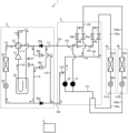
- Fig. 1 is a refrigerant circuit diagram of an air conditioner 1 according to embodiment 1. As shown in Fig. 1, the air conditioner 1 has an outdoor unit 2, a relay unit 3, a first indoor unit 4a, and a second indoor unit 4b.
- the outdoor unit 2 and the repeater unit 3 are connected by a low-pressure main pipe 101 and a high-pressure main pipe 102. Refrigerant flowing from the repeater unit 3 to the outdoor unit 2 passes through the low-pressure main pipe 101. Refrigerant flowing from the outdoor unit 2 to the repeater unit 3 passes through the high-pressure main pipe 102. Refrigerant with a higher pressure than the refrigerant flowing through the low-pressure main pipe 101 flows through the high-pressure main pipe 102.
- the relay unit 3 and the first indoor unit 4a are connected by the first gas branch pipe 103a and the first liquid branch pipe 104a.
- the relay unit 3 and the second indoor unit 4b are connected by the second gas branch pipe 103b and the second liquid branch pipe 104b.
- Gas refrigerant flows through the first gas branch pipe 103a and the second gas branch pipe 103b regardless of the operation mode of the air conditioning device 1.
- Gas-liquid two-phase refrigerant or liquid refrigerant flows through the first liquid branch pipe 104a and the second liquid branch pipe 104b regardless of the operation mode of the air conditioning device 1.
- the outdoor unit 2 is a device that supplies hot or cold heat to the first indoor unit 4a and the second indoor unit 4b.
- the outdoor unit 2 has outdoor piping 111-115, a suction pipe 116, and a discharge pipe 117.
- the outdoor unit 2 includes a compressor 21, an outdoor flow path switching device 22, an outdoor heat exchanger 23, an outdoor expansion valve 24, an accumulator 25, check valves 26a-26d, a frost detection device 27, and a defrost detection device 28.
- the outdoor pipe 111 is a pipe that connects the outdoor flow path switching device 22 and the low pressure main pipe 101.
- the outdoor pipe 112 is a pipe that connects the outdoor flow path switching device 22, the outdoor heat exchanger 23, the outdoor expansion valve 24, and the high pressure main pipe 102.
- the outdoor pipe 113 is a pipe that connects the outdoor flow path switching device 22 and the accumulator 25.
- the outdoor pipe 114 is a pipe that connects the outdoor pipe 111 and the outdoor pipe 112.
- the outdoor pipe 115 is a pipe that connects the outdoor pipe 111 and the outdoor pipe 112.
- the suction pipe 116 is a pipe that connects the accumulator 25 and the suction side of the compressor 21.
- the discharge pipe 117 is a pipe that connects the discharge side of the compressor 21 and the outdoor flow path switching device 22.
- the compressor 21 sucks in a refrigerant in a low temperature and low pressure state, compresses the sucked refrigerant, and discharges it as a refrigerant in a high temperature and high pressure state.
- the outdoor flow path switching device 22 is, for example, a four-way valve.
- the outdoor flow path switching device 22 switches the connection direction of the pipe through which the refrigerant discharged from the compressor 21 flows. Specifically, the outdoor flow path switching device 22 switches the connection direction of the pipe between the connection direction of the outdoor heat exchanger 23 and the compressor 21 and the connection direction of the outdoor heat exchanger 23 and the accumulator 25. This switches the flow direction of the refrigerant in the refrigerant circuit.
- the outdoor heat exchanger 23 exchanges heat between the refrigerant and the outdoor air.
- the outdoor heat exchanger 23 functions as a condenser with a heat dissipation effect during cooling operation, and functions as an evaporator with a heat absorption effect during heating operation.
- the outdoor expansion valve 24 reduces the pressure of the refrigerant and expands it, and is, for example, an electronic expansion valve with an adjustable opening.
- the accumulator 25 is a device for storing excess refrigerant circulating through the outdoor unit 2.
- Check valve 26a is provided in outdoor pipe 111 between the point where outdoor pipe 114 is connected and the point where outdoor pipe 115 is connected.
- Check valve 26a allows the flow of refrigerant flowing through outdoor pipe 111 from low-pressure main pipe 101 to outdoor flow path switching device 22, and blocks the flow of refrigerant flowing from outdoor flow path switching device 22 to low-pressure main pipe 101.
- Check valve 26b is provided in outdoor pipe 115.
- Check valve 26b allows the flow of refrigerant flowing through outdoor pipe 115 from outdoor pipe 111 to outdoor pipe 112, and blocks the flow of refrigerant flowing from outdoor pipe 112 to outdoor pipe 111.
- Check valve 26c is provided in outdoor pipe 114.
- Check valve 26c allows the flow of refrigerant through outdoor pipe 114 from outdoor pipe 111 to outdoor pipe 112, and blocks the flow of refrigerant from outdoor pipe 112 to outdoor pipe 111.
- Check valve 26d is provided in outdoor pipe 112 between the point where outdoor pipe 114 is connected and the point where outdoor pipe 115 is connected.
- Check valve 26d allows the flow of refrigerant through outdoor pipe 112 from outdoor expansion valve 24 to high-pressure main pipe 102, and blocks the flow of refrigerant from high-pressure main pipe 102 to outdoor expansion valve 24.
- the relay unit 3 is a device that relays hot or cold energy supplied from the outdoor unit 2 via a refrigerant to the first indoor unit 4a and the second indoor unit 4b via the refrigerant or heat medium.
- the relay unit 3 also blocks the supply of hot or cold energy from the outdoor unit 2 to the first indoor unit 4a and the second indoor unit 4b via the refrigerant or heat medium.
- the relay unit 3 has a liquid relay pipe 121 and a gas relay pipe 124.
- the relay unit 3 has a low pressure relay expansion valve 31, a high pressure relay expansion valve 32, a first low pressure valve 33a, a second low pressure valve 33b, a first high pressure valve 34a, and a second high pressure valve 34b.
- the liquid relay pipe 121 connects the first liquid branch pipe 104a and the second liquid branch pipe 104b to the low pressure main pipe 101 and the high pressure main pipe 102.
- the liquid relay pipe 121 is a pipe that branches into a low pressure side and a high pressure side, and has a low pressure liquid branch pipe 122 and a high pressure liquid branch pipe 123.
- the low pressure liquid branch pipe 122 is a pipe that connects the branched portion of the liquid relay pipe 121 to the low pressure main pipe 101.
- the high pressure liquid branch pipe 123 is a pipe that connects the branched portion of the liquid relay pipe 121 to the high pressure main pipe 102.
- the liquid relay pipe 121 branches corresponding to the first indoor unit 4a and the second indoor unit 4b.
- the gas relay pipe 124 connects the first gas branch pipe 103a and the second gas branch pipe 103b to the low-pressure liquid branch pipe 122 and the high-pressure liquid branch pipe 123.
- the gas relay pipe 124 is a pipe that branches into a low-pressure side and a high-pressure side, and has a low-pressure gas branch pipe 125 and a high-pressure gas branch pipe 126.
- the low-pressure gas branch pipe 125 is a pipe that connects the branched portion of the gas relay pipe 124 to the low-pressure liquid branch pipe 122.
- the low-pressure gas branch pipe 125 branches in correspondence with the first indoor unit 4a and the second indoor unit 4b.
- the high-pressure gas branch pipe 126 is a pipe that connects the branched portion of the gas relay pipe 124 to the high-pressure liquid branch pipe 123.
- the high-pressure gas branch pipe 126 branches in correspondence with the first indoor unit 4a and the second indoor unit 4b.
- the low-pressure relay expansion valve 31 is provided in the low-pressure liquid branch pipe 122 at a portion closer to the liquid branch pipe 104 than the connection portion of the low-pressure gas branch pipe 125.
- the low-pressure relay expansion valve 31 reduces the pressure of the refrigerant to expand it, and is, for example, an electronic expansion valve with an adjustable opening.
- the high-pressure relay expansion valve 32 is provided in the high-pressure liquid branch pipe 123 at a portion closer to the liquid branch pipe 104 than the connection portion of the high-pressure gas branch pipe 126.
- the high-pressure relay expansion valve 32 reduces the pressure of the refrigerant to expand it, and is, for example, an electronic expansion valve with an adjustable opening.
- the first low pressure valve 33a is provided at a position corresponding to the first indoor unit 4a in the low pressure gas branch pipe 125 that branches into the first indoor unit 4a and the second indoor unit 4b.
- the first low pressure valve 33a has a function of switching between an open state that allows the flow of refrigerant flowing through the region of the low pressure gas branch pipe 125 that corresponds to the first indoor unit 4a and a closed state that blocks the flow of refrigerant flowing through the region of the low pressure gas branch pipe 125 that corresponds to the first indoor unit 4a.
- the second low pressure valve 33b is provided at a position corresponding to the second indoor unit 4b in the low pressure gas branch pipe 125 that branches into the first indoor unit 4a and the second indoor unit 4b.
- the second low pressure valve 33b has a function of switching between an open state that allows the flow of refrigerant flowing through the region of the low pressure gas branch pipe 125 that corresponds to the second indoor unit 4b and a closed state that blocks the flow of refrigerant flowing through the region of the low pressure gas branch pipe 125 that corresponds to the second indoor unit 4b.
- the first high pressure valve 34a is provided at a position corresponding to the first indoor unit 4a in the high pressure gas branch pipe 126 that branches into the first indoor unit 4a and the second indoor unit 4b.
- the first high pressure valve 34a has a function of switching between an open state that allows the flow of refrigerant flowing through the area of the high pressure gas branch pipe 126 that corresponds to the first indoor unit 4a and a closed state that blocks the flow of refrigerant flowing through the area of the high pressure gas branch pipe 126 that corresponds to the first indoor unit 4a.
- the second high pressure valve 34b is provided at a position corresponding to the second indoor unit 4b in the high pressure gas branch pipe 126 that branches into the first indoor unit 4a and the second indoor unit 4b.
- the second high pressure valve 34b has a function of switching between an open state that allows the flow of refrigerant flowing through the area of the high pressure gas branch pipe 126 that corresponds to the second indoor unit 4b and a closed state that blocks the flow of refrigerant flowing through the area of the high pressure gas branch pipe 126 that corresponds to the second indoor unit 4b.
- the first low pressure valve 33a, the second low pressure valve 33b, the first high pressure valve 34a, and the second high pressure valve 34b are not limited in type as long as they have a mechanism that can switch between allowing and blocking the flow of refrigerant. Therefore, these valves may be, for example, opening and closing valves or expansion valves.
- the first indoor unit 4a and the second indoor unit 4b are devices for supplying hot or cold heat to the room.
- the first indoor unit 4a has a first indoor refrigerant piping 131a.
- the first indoor unit 4a is equipped with a first indoor refrigerant heat exchanger 41a and a first indoor expansion valve 42a.
- the first indoor refrigerant piping 131a connects the first gas branch pipe 103a, the first indoor refrigerant heat exchanger 41a, the first indoor expansion valve 42a, and the first liquid branch pipe 104a, and is a pipe through which refrigerant flows.
- the second indoor unit 4b has a second indoor refrigerant piping 131b.
- the second indoor unit 4b is equipped with a second indoor refrigerant heat exchanger 41b and a second indoor expansion valve 42b.
- the second indoor refrigerant pipe 131b is a pipe that connects the second gas branch pipe 103b, the second indoor refrigerant heat exchanger 41b, the second indoor expansion valve 42b, and the second liquid branch pipe 104b, and through which the refrigerant flows.
- the first indoor refrigerant heat exchanger 41a and the second indoor refrigerant heat exchanger 41b exchange heat between the indoor air and the refrigerant.
- the first indoor refrigerant heat exchanger 41a and the second indoor refrigerant heat exchanger 41b act as evaporators during cooling operation and as condensers during heating operation.
- the first indoor expansion valve 42a and the second indoor expansion valve 42b reduce the pressure of the refrigerant to expand it, and are, for example, electronic expansion valves with adjustable opening.
- the number of indoor units 4 in the air conditioning device 1 is not limited to two, and may be one, three or more.
- the first indoor unit 4a and the second indoor unit 4b are not particularly distinguished, they and their corresponding configurations may be referred to as follows. That is, when the first indoor unit 4a and the second indoor unit 4b are not distinguished, they are referred to as indoor units 44.
- the first gas branch pipe 103a and the second gas branch pipe 103b are not distinguished, they are referred to as gas branch pipe 103.
- the first liquid branch pipe 104a and the second liquid branch pipe 104b are not distinguished, they are referred to as liquid branch pipe 104.
- first low pressure valve 33a and the second low pressure valve 33b are not distinguished, they are referred to as low pressure valve 33.
- first high pressure valve 34a and the second high pressure valve 34b are not distinguished, they are referred to as high pressure valve 34.
- the indoor refrigerant heat exchanger 41a and the second indoor refrigerant heat exchanger 41b are not differentiated from each other, they are referred to as the indoor refrigerant heat exchanger 41.
- the indoor expansion valve 42a and the second indoor expansion valve 42b are not differentiated from each other, they are referred to as the indoor expansion valve 42.
- the air conditioning device 1 has a control device 5 that controls each device of the outdoor unit 2, relay unit 3, and indoor unit 4.
- the control device 5 controls the execution of various operation modes.
- the operation modes executed by the air conditioning device 1 of embodiment 1 include heating operation, defrosting operation, and cooling operation.
- the user instructs the execution of heating operation and cooling operation using a remote control (not shown) or the like.
- the defrosting operation is an operation mode for removing frost that has formed on the outdoor heat exchanger 23 during heating operation.
- FIG. 2 is a hardware configuration diagram showing an example of the configuration of the control device 5 according to the first embodiment.
- the control device 5 is configured by a processing circuit 201 as shown in FIG. 2.
- the processing circuit 201 is, for example, a single circuit, a composite circuit, a programmed processor 202, a parallel programmed processor 202, an ASIC (Application Specific Integrated Circuit), an FPGA (Field-Programmable Gate Array), or a combination of these.
- Each function realized by the processing circuit 201 may be realized by separate hardware, or each function may be realized by a single piece of hardware.
- FIG. 3 is a hardware configuration diagram showing an example of the configuration of the control device 5 according to the first embodiment.
- the control device 5 is composed of a processor 202 such as a CPU and a memory 203, as shown in FIG. 3.
- FIG. 3 shows that the processor 202 and the memory 203 are communicatively connected to each other via a bus 204.
- Each function of the control device 5 is realized by software, firmware, or a combination of software and firmware.
- the software and firmware are written as programs and stored in the memory 203.
- the processor 202 realizes the functions of each means by reading and executing the programs stored in the memory 203.
- a non-volatile semiconductor memory such as a ROM (Read Only Memory), a flash memory, an EPROM (Erasable and Programmable ROM), and an EEPROM (Electrically Erasable and Programmable ROM) may be used.
- a volatile semiconductor memory such as a RAM (Random Access Memory) may be used as the memory 203.
- a removable recording medium such as a magnetic disk, a flexible disk, an optical disk, a CD (Compact Disc), an MD (Mini Disc), and a DVD (Digital Versatile Disc) may be used as the memory 203.
- some of the functions of the processing circuit 201 may be realized by dedicated hardware, and some may be realized by software or firmware.
- FIG. 4 is a functional block diagram showing the air conditioning apparatus 1 according to the first embodiment.
- the control device 5 controls the compressor 21, outdoor flow path switching device 22, and outdoor expansion valve 24 of the outdoor unit 2 according to the operation mode.
- the control device 5 also controls the low pressure relay expansion valve 31, high pressure relay expansion valve 32, low pressure valve 33, and high pressure valve 34 of the relay unit 3 according to the operation mode.
- the control device 5 controls the indoor expansion valve 42 of the indoor unit 44 according to the operation mode.
- the control device 5 transitions the operation mode based on the measurement results of the frost detection device 27 and the defrost detection device 28.
- the frost detection device 27 is a sensor for detecting frost on the outdoor heat exchanger 23, and is, for example, a pressure sensor.
- the frost detection device 27 is not particularly limited, but is, for example, arranged in the piping between the outdoor heat exchanger 23 and the compressor 21.
- the frost detection device 27 transmits the measurement result to the control device 5.
- the control device 5 determines, based on the measurement result of the frost detection device 27, that frost has occurred in the outdoor heat exchanger 23 to the extent that defrosting is required, the control device 5 transitions the operation mode from heating operation to defrosting operation.
- the control device 5 determines that frost has occurred in the outdoor heat exchanger 23 to the extent that defrosting is required.
- the defrost detection means is a sensor for detecting defrost from the outdoor heat exchanger 23, and is, for example, a temperature sensor.
- the defrost detection device 28 is arranged in the piping between the outdoor heat exchanger 23 and the compressor 21.
- the defrost detection device 28 transmits the measurement result to the control device 5.
- the control device 5 determines that the defrosting of the outdoor heat exchanger 23 is completed based on the measurement result of the defrost detection device 28, it transitions the operation mode from the defrosting operation to the heating operation. For example, when the temperature of the refrigerant measured by the defrost detection device 28 exceeds a predetermined threshold, the control device 5 determines that the defrosting of the outdoor heat exchanger 23 is completed.
- FIG. 5 is a diagram for explaining the heating operation of the air conditioner 1 according to the first embodiment.
- the arrows indicate the direction of the refrigerant flow.
- the control device 5 switches the outdoor flow path switching device 22 to a direction that connects the outdoor heat exchanger 23 and the accumulator 25.
- the control device 5 also opens the low-pressure relay expansion valve 31 and closes the high-pressure relay expansion valve 32.
- the control device 5 closes the low-pressure valve 33 and opens the high-pressure valve 34.
- the control device 5 then opens the indoor expansion valve 42 and the outdoor expansion valve 24.
- the refrigerant sucked into the compressor 21 is compressed by the compressor 21 and discharged in a high-temperature, high-pressure gas state.
- the high-temperature, high-pressure gas refrigerant discharged from the compressor 21 passes through the high-pressure main pipe 102 via the outdoor piping 115 equipped with a check valve 26b, and flows into the relay unit 3.
- the refrigerant that flows into the relay unit 3 passes through a part of the high-pressure liquid branch pipe 123, the high-pressure gas branch pipe 126 equipped with a high-pressure valve 34, and the gas branch pipe 103, and flows into the indoor unit 4.
- the high-temperature, high-pressure gas refrigerant that flows into the indoor unit 4 passes through the indoor refrigerant heat exchanger 41, which acts as a condenser.
- the refrigerant that passes through the indoor refrigerant heat exchanger 41 exchanges heat with the indoor air, condenses, and liquefies. At this time, the indoor air is warmed, and heating is performed in the room.
- the liquid refrigerant passes through the indoor expansion valve 42, is decompressed and expanded, and becomes a low-temperature, low-pressure gas-liquid two-phase refrigerant.
- the refrigerant in the gas-liquid two-phase state passes through the liquid branch pipe 104 and flows into the relay unit 3.
- the refrigerant that flows into the relay unit 3 passes through the low-pressure liquid branch pipe 122, which is provided with the low-pressure relay expansion valve 31, and the low-pressure main pipe 101, and flows into the outdoor unit 2.
- the refrigerant that flows into the outdoor unit 2 passes through the outdoor expansion valve 24 via the outdoor piping 114, which is provided with the check valve 26c, and is further reduced in pressure and expanded, and passes through the outdoor heat exchanger 23, which acts as an evaporator.
- the refrigerant that passes through the outdoor heat exchanger 23 exchanges heat with the outdoor air and evaporates and gasifies.
- the evaporated low-temperature, low-pressure gaseous refrigerant then passes through the outdoor flow switching device 22 and the accumulator 25, and is sucked back into the compressor 21 and circulates.
- FIG. 6 is a diagram for explaining the defrosting operation of the air conditioning apparatus 1 according to the first embodiment.
- the arrows indicate the direction of refrigerant flow.
- the control device 5 switches the outdoor flow path switching device 22 to a direction that connects the outdoor heat exchanger 23 and the accumulator 25.
- the control device 5 also closes the low pressure relay expansion valve 31 and closes the high pressure relay expansion valve 32.
- the control device 5 opens the low pressure valve 33 and opens the high pressure valve 34.
- the control device 5 then opens the indoor expansion valve 42 and opens the outdoor expansion valve 24. Note that the indoor expansion valve 42 may be closed.
- the refrigerant sucked into the compressor 21 is compressed by the compressor 21 and discharged in a high-temperature, high-pressure gas state.
- the high-temperature, high-pressure gas refrigerant discharged from the compressor 21 passes through the high-pressure main pipe 102 via the outdoor piping 115 equipped with a check valve 26b, and flows into the relay unit 3.
- the refrigerant that flows into the relay unit 3 passes through a part of the high-pressure liquid branch pipe 123, the high-pressure gas branch pipe 126 equipped with a high-pressure valve 34, the low-pressure gas branch pipe 125 equipped with a low-pressure valve 33, a part of the low-pressure liquid branch pipe 122, and the low-pressure main pipe 101, and flows back into the outdoor unit 2.
- the high-temperature, high-pressure gas refrigerant that flows into the outdoor unit 2 passes through the outdoor expansion valve 24 via the outdoor piping 114 equipped with a check valve 26c, where it is decompressed and expanded, becoming a high-temperature, low-pressure gas refrigerant, which passes through the outdoor heat exchanger 23.
- the high-temperature, low-pressure gaseous refrigerant passing through the outdoor heat exchanger 23 exchanges heat with the frost adhering to the outdoor heat exchanger 23, and becomes a low-temperature, low-pressure gaseous refrigerant.
- the outdoor heat exchanger 23 is defrosted.
- the low-temperature, low-pressure gaseous refrigerant then passes through the outdoor flow switching device 22 and the accumulator 25, and is again sucked into the compressor 21 and circulated. In this way, in the defrosting operation of the first embodiment, high-temperature refrigerant circulates between the outdoor unit 2 and the relay unit 3, and the flow of refrigerant to the indoor unit 44, and thus the supply of heat, is blocked.
- FIG. 7 is a flowchart showing the operation of the control device 5 according to the first embodiment.
- the execution of the defrosting operation will be described with reference to FIG. 7.
- the control device 5 determines whether or not defrosting of the outdoor heat exchanger 23 is necessary based on the measurement result of the frost detection device 27 (step S1). If it is determined that defrosting of the outdoor heat exchanger 23 is unnecessary (step S1: NO), the process of step S1 is repeated until it is determined that defrosting of the outdoor heat exchanger 23 is necessary. If it is determined that defrosting of the outdoor heat exchanger 23 is necessary (step S1: YES), the low-pressure valve 33 is changed to an open state (step S2). Then, the low-pressure relay expansion valve 31 is closed (step S3). This causes the operation mode to transition from the heating operation to the defrosting operation.
- step S4 determines whether the defrosting of the outdoor heat exchanger 23 has been completed based on the measurement result of the defrosting detection device 28 (step S4). If it is determined that the defrosting of the outdoor heat exchanger 23 is not completed (step S4: NO), the process of step S4 is repeated until it is determined that the defrosting of the outdoor heat exchanger 23 has been completed. If it is determined that the defrosting of the outdoor heat exchanger 23 has been completed (step S4: YES), the low-pressure relay expansion valve 31 is opened (step S5). Then, the low-pressure valve 33 is changed to a closed state (step S6). This causes the operation mode to transition from the defrosting operation to the heating operation.
- the air conditioning device 1 of the first embodiment controls the relay unit 3 to cut off the supply of heat to the indoor unit 4 during defrost operation, and controls the outdoor flow path switching device 22 to allow the refrigerant discharged from the compressor 21 to flow to the relay unit 3 without passing through the outdoor heat exchanger 23. Therefore, the outdoor unit 2, the relay unit 3, and the main pipe connecting the outdoor unit 2 and the relay unit 3 are prevented from dropping in temperature during defrost operation by circulating high-temperature refrigerant. In addition, the temperature of the indoor unit 4, in which refrigerant does not circulate, and the branch pipe connecting the relay unit 3 and the indoor unit 4 are also prevented from dropping during defrost operation.
- the air conditioning device 1 of the first embodiment it is not necessary to reheat the outdoor unit 2, the relay unit 3, the indoor unit 4, and the main pipe and branch pipe when heating is resumed, and the heating resume time from the end of the defrost operation to the start of actual heating in the room can be shortened.
- FIG. 8 is a refrigerant circuit diagram for explaining the defrosting operation of the air conditioner 1 according to the first modification of the first embodiment.
- the arrows indicate the direction of the refrigerant flow.
- the control device 5 switches the outdoor flow path switching device 22 to a direction that connects the outdoor heat exchanger 23 and the accumulator 25.
- the control device 5 opens the low pressure relay expansion valve 31 and opens the high pressure relay expansion valve 32.
- the control device 5 closes the low pressure valve 33 and opens the high pressure valve 34. Then, the control device 5 closes the indoor expansion valve 42 and opens the outdoor expansion valve 24.
- the refrigerant sucked into the compressor 21 is compressed by the compressor 21 and discharged in a high-temperature, high-pressure gas state.
- the high-temperature, high-pressure gas state refrigerant discharged from the compressor 21 passes through the high-pressure main pipe 102 via the outdoor piping 115 equipped with a check valve 26b, and flows into the relay unit 3.
- the refrigerant that flows into the relay unit 3 passes through the high-pressure liquid branch pipe 123 equipped with a high-pressure relay expansion valve 32, the low-pressure liquid branch pipe 122 equipped with a low-pressure relay expansion valve 31, and the low-pressure main pipe 101, and flows back into the outdoor unit 2.
- the high-temperature, high-pressure gas state refrigerant that flows into the outdoor unit 2 passes through the outdoor expansion valve 24 via the outdoor piping 114 equipped with a check valve 26c, where it is decompressed and expanded, becoming a high-temperature, low-pressure gas state refrigerant that passes through the outdoor heat exchanger 23.
- the high-temperature, low-pressure gaseous refrigerant passing through the outdoor heat exchanger 23 exchanges heat with the frost adhering to the outdoor heat exchanger 23, and becomes a low-temperature, low-pressure gaseous state. At this time, the outdoor heat exchanger 23 is defrosted.
- the low-temperature, low-pressure gaseous refrigerant then passes through the outdoor flow path switching device 22 and the accumulator 25, and is again sucked into the compressor 21 and circulated. In this way, even in the defrosting operation of the first modification of the first embodiment, high-temperature refrigerant circulates between the outdoor unit 2 and the relay unit 3, and the flow of refrigerant to the indoor unit 44, and the supply of heat, are blocked.
- FIG. 9 is a flowchart showing the operation of the control device 5 according to the first modification of the first embodiment.
- the execution of the defrosting operation will be described with reference to FIG. 9.
- the control device 5 determines whether or not defrosting of the outdoor heat exchanger 23 is necessary based on the measurement result of the frost detection device 27 (step S11). If it is determined that defrosting of the outdoor heat exchanger 23 is unnecessary (step S11: NO), the process of step S11 is repeated until it is determined that defrosting of the outdoor heat exchanger 23 is necessary. If it is determined that defrosting of the outdoor heat exchanger 23 is necessary (step S11: YES), the high-pressure relay expansion valve 32 is opened (step S12). Then, the indoor expansion valve 42 is closed (step S13). This causes the operation mode to transition from the heating operation to the defrosting operation.
- step S14 determines whether the defrosting of the outdoor heat exchanger 23 has been completed based on the measurement result of the defrosting detection device 28 (step S14). If it is determined that the defrosting of the outdoor heat exchanger 23 is not completed (step S14: NO), the process of step S14 is repeated until it is determined that the defrosting of the outdoor heat exchanger 23 has been completed. If it is determined that the defrosting of the outdoor heat exchanger 23 has been completed (step S14: YES), the indoor expansion valve 42 is opened (step S15). Then, the high-pressure relay expansion valve 32 is closed (step S16). This causes the operation mode to transition from the defrosting operation to the heating operation.
- the air conditioning apparatus 1 of Variation 1 of Embodiment 1 also controls the relay unit 3 to cut off the supply of heat to the indoor unit 4 during defrost operation, and controls the outdoor flow path switching device 22 to cause the refrigerant discharged from the compressor 21 to flow through the relay unit 3 without passing through the outdoor heat exchanger 23. Therefore, with the air conditioning apparatus 1 of Variation 1 of Embodiment 1, it does not take time to reheat the outdoor unit 2, relay unit 3, indoor unit 4, and main pipe and branch pipe when heating is resumed. Therefore, the heating restoration time from the end of defrost operation to the actual start of heating indoors can be shortened.
- the first high pressure valve 34a may be closed. Or, both the first indoor expansion valve 42a and the first high pressure valve 34a may be closed.
- the second high pressure valve 34b may be closed. Or, both the second indoor expansion valve 42b and the second high pressure valve 34b may be closed.
- the air conditioning apparatus 1 may control the devices differently from the devices in the defrosting operation shown in the first embodiment and the first modified example of the first embodiment.
- FIG. 10 is a refrigerant circuit diagram for explaining the defrosting operation of the air conditioning apparatus 1 according to the second modified example of the first embodiment.
- the arrows indicate the direction of the refrigerant flow.
- the control device 5 switches the outdoor flow path switching device 22 to a direction that connects the outdoor heat exchanger 23 and the accumulator 25.
- the control device 5 opens the low pressure relay expansion valve 31 and opens the high pressure relay expansion valve 32.
- the control device 5 opens the low pressure valve 33 and opens the high pressure valve 34. Then, the control device 5 closes the indoor expansion valve 42 and opens the outdoor expansion valve 24.
- a main circuit and a bypass circuit are formed.
- the refrigerant sucked into the compressor 21 is compressed by the compressor 21 and discharged in a high-temperature, high-pressure gas state.
- the high-temperature, high-pressure gas refrigerant discharged from the compressor 21 passes through the high-pressure main pipe 102 via the outdoor piping 115 provided with a check valve 26b, and flows into the relay unit 3.
- the refrigerant that flows into the relay unit 3 passes through a part of the high-pressure liquid branch pipe 123, the high-pressure gas branch pipe 126 provided with a high-pressure valve 34, the low-pressure gas branch pipe 125 provided with a low-pressure valve 33, a part of the low-pressure liquid branch pipe 122, and the low-pressure main pipe 101, and flows back into the outdoor unit 2.
- the high-temperature, high-pressure gas refrigerant that flows into the outdoor unit 2 passes through the outdoor expansion valve 24 via the outdoor piping 114 provided with a check valve 26c, is decompressed and expanded, and becomes a high-temperature, low-pressure gas refrigerant, which passes through the outdoor heat exchanger 23.
- the high-temperature, low-pressure gaseous refrigerant passing through the outdoor heat exchanger 23 exchanges heat with the frost adhering to the outdoor heat exchanger 23, and becomes a low-temperature, low-pressure gaseous refrigerant.
- the outdoor heat exchanger 23 is defrosted.
- the low-temperature, low-pressure gaseous refrigerant then passes through the outdoor flow switching device 22 and the accumulator 25, and is sucked back into the compressor 21 and circulated.
- the refrigerant flowing through the bypass circuit branches off from the main circuit, passes through high-pressure liquid branch pipe 123, in which high-pressure relay expansion valve 32 is provided, and low-pressure liquid branch pipe 122, in which low-pressure relay expansion valve 31 is provided, and merges into the main circuit.
- high-temperature refrigerant circulates between the outdoor unit 2 and the relay unit 3, and the flow of refrigerant to the indoor unit 44, and thus the supply of heat, is blocked.
- FIG. 11 is a flowchart showing the operation of the control device 5 according to the first modification of the first embodiment. The execution of the defrosting operation will be described based on FIG. 11.
- the control device 5 judges whether or not defrosting of the outdoor heat exchanger 23 is necessary based on the measurement result of the frost detection device 27 (step S21). If it is judged that defrosting of the outdoor heat exchanger 23 is unnecessary (step S21: NO), the process of step S21 is repeated until it is judged that defrosting of the outdoor heat exchanger 23 is necessary.
- step S21 If it is judged that defrosting of the outdoor heat exchanger 23 is necessary (step S21: YES), the low pressure valve 33 is changed to an open state and the high pressure relay expansion valve 32 is opened (step S22). Then, the indoor expansion valve 42 is closed (step S23). This causes the operation mode to transition from the heating operation to the defrosting operation.
- step S24 determines whether the defrosting of the outdoor heat exchanger 23 has been completed based on the measurement result of the defrosting detection device 28 (step S24). If it is determined that the defrosting of the outdoor heat exchanger 23 is not completed (step S24: NO), the process of step S24 is repeated until it is determined that the defrosting of the outdoor heat exchanger 23 has been completed. If it is determined that the defrosting of the outdoor heat exchanger 23 has been completed (step S24: YES), the indoor expansion valve 42 is opened (step S25). After that, the low pressure valve 33 is changed to a closed state, and the high pressure relay expansion valve 32 is closed (step S26). This causes the operation mode to transition from the defrosting operation to the heating operation.
- the air conditioning apparatus 1 of Variation 2 of Embodiment 1 also controls the relay unit 3 to cut off the supply of heat to the indoor unit 4 during defrost operation, and controls the outdoor flow path switching device 22 to cause the refrigerant discharged from the compressor 21 to flow through the relay unit 3 without passing through the outdoor heat exchanger 23. Therefore, with the air conditioning apparatus 1 of Variation 2 of Embodiment 1, no time is required to reheat the outdoor unit 2, relay unit 3, indoor unit 4, and main pipe and branch pipe when heating is resumed. Therefore, the heating restoration time from the end of defrost operation to the actual start of heating indoors can be shortened.
- the first low pressure valve 33a, the second low pressure valve 33b, and the high pressure relay expansion valve 32 may not all be opened, and only the high pressure relay expansion valve 32 or the first low pressure valve 33a and the second low pressure valve 33b may be opened.
- Embodiment 2 differs from the first embodiment in that the indoor refrigerant heat exchanger 41 is a device that exchanges heat between the heat medium and the air.
- the same parts as those in the first embodiment are denoted by the same reference numerals and the description thereof is omitted, and the description will be centered on the differences from the first embodiment.
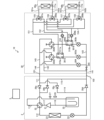
- FIG. 12 is a refrigerant circuit diagram and a water circuit diagram of an air conditioning apparatus 10 according to embodiment 2.
- the configuration of the outdoor unit 2 is the same as that of embodiment 1, and therefore a description thereof is omitted.
- the relay unit 30 and the first indoor unit 40a are connected by a first high-pressure branch pipe 161a and a first low-pressure branch pipe 162a.
- the relay unit 30 and the second indoor unit 40b are connected by a second high-pressure branch pipe 161b and a second low-pressure branch pipe 162b.
- a heat medium flows through the first high-pressure branch pipe 161a and the second high-pressure branch pipe 161b, and the first low-pressure branch pipe 162a and the second low-pressure branch pipe 162b.
- the heat medium is a fluid other than a refrigerant, such as water or brine.
- the relay unit 30 has a high-pressure relay pipe 141, a low-pressure relay pipe 144, and a relay connection pipe 145.
- the relay unit 30 also has a first relay heat exchanger 301a, a second relay heat exchanger 301b, a first relay flow path switching device 302a, a second relay flow path switching device 302b, a first main expansion valve 303a, a second main expansion valve 303b, a sub-expansion valve 304, and a relay switching valve 305.
- the high-pressure relay pipe 141 is a pipe that connects the high-pressure main pipe 102 to the inlet and outlet of the first heat medium flow path 311a of the first relay heat exchanger 301a described later.
- the high-pressure relay pipe 141 also connects the high-pressure main pipe 102 to the inlet and outlet of the second heat medium flow path 311b of the second relay heat exchanger 301b described later.
- the high-pressure relay pipe 141 has an inlet branch pipe 142 that connects to the inlet, and an outlet branch pipe 143 that connects to the outlet.
- the inlet branch pipe 142 and the outlet branch pipe 143 are branched in correspondence with the first relay heat exchanger 301a and the second relay heat exchanger 301b.
- the low-pressure relay pipe 144 is a pipe that connects the low-pressure main pipe 101 to the outlet branch pipe 143.
- the first relay heat exchanger 301a has a first refrigerant flow path 310a through which the refrigerant that has been heat exchanged in the outdoor heat exchanger 23 flows, and a first heat medium flow path 311a through which the heat medium that has been heat exchanged in the indoor refrigerant heat exchanger 41 flows.
- the first relay heat exchanger 301a performs heat exchange between the refrigerant flowing in the first refrigerant flow path 310a and the heat medium flowing in the first heat medium flow path 311a.
- the second relay heat exchanger 301b has a second refrigerant flow path 310b through which the refrigerant that has been heat exchanged in the outdoor heat exchanger 23 flows, and a second heat medium flow path 311b through which the heat medium that has been heat exchanged in the indoor refrigerant heat exchanger 41 flows.
- the second relay heat exchanger 301b performs heat exchange between the refrigerant flowing in the second refrigerant flow path 310b and the heat medium flowing in the second heat medium flow path 311b.
- the first relay flow path switching device 302a switches between an orientation in which the first relay heat exchanger 301a is connected to the low-pressure main pipe 101 and an orientation in which the first relay heat exchanger 301a is connected to the high-pressure main pipe 102.
- the second relay flow path switching device 302b switches between an orientation in which the second relay heat exchanger 301b is connected to the low-pressure main pipe 101 and an orientation in which the second relay heat exchanger 301b is connected to the high-pressure main pipe 102.
- the first main expansion valve 303a is provided at a position corresponding to the first relay heat exchanger 301a in the outflow branch pipe 143 that branches into the first relay heat exchanger 301a and the second relay heat exchanger 301b.
- the first main expansion valve 303a is provided at a portion of the outflow branch pipe 143 that is closer to the first relay heat exchanger 301a than the connection portion of the low-pressure relay pipe 144.
- the first main expansion valve 303a reduces the pressure of the refrigerant flowing through the area of the outflow branch pipe 143 that corresponds to the first relay heat exchanger 301a and is, for example, an electronic expansion valve whose opening is adjustable.
- the second main expansion valve 303b is provided at a position corresponding to the second relay heat exchanger 301b in the outflow branch pipe 143 that branches into the first relay heat exchanger 301a and the second relay heat exchanger 301b.
- the second main expansion valve 303b is provided in a portion of the outflow branch pipe 143 that is closer to the second relay heat exchanger 301b than the connection portion of the low-pressure relay pipe 144.
- the second main expansion valve 303b reduces the pressure of the refrigerant flowing through the region of the outflow branch pipe 143 that corresponds to the second relay heat exchanger 301b, and expands it, and is, for example, an electronic expansion valve with an adjustable opening.
- the sub-expansion valve 304 is provided in the low-pressure relay pipe 144.
- the sub-expansion valve 304 reduces the pressure of the refrigerant flowing through the low-pressure relay pipe 144 and expands it, and is, for example, an electronic expansion valve with an adjustable opening.
- the relay switching valve 305 is provided in a portion of the outflow branch pipe 143 that is closer to the high-pressure main pipe 102 than the connection portion of the low-pressure relay pipe 144.
- the relay switching valve 305 has a function of switching between an open state that allows the flow of refrigerant through the outflow branch pipe 143 and a closed state that blocks the flow of refrigerant through the outflow branch pipe 143.
- the relay unit 30 has heat medium supply pipes 151 and 152, heat medium return pipes 153 and 154, and heat medium piping 155 to 158.
- the relay unit 30 also has a first pump 306a, a second pump 306b, a first mixed three-way valve 307a, a second mixed three-way valve 307b, a first diverting three-way valve 308a, and a second diverting three-way valve 308b.
- the heat medium supply pipe 151 is a pipe that connects the outlet of the first heat medium flow path 311a of the first relay heat exchanger 301a to the first mixed three-way valve 307a and the second mixed three-way valve 307b.
- the heat medium supply pipe 152 is a pipe that connects the outlet of the second heat medium flow path 311b of the second relay heat exchanger 301b to the first mixed three-way valve 307a and the second mixed three-way valve 307b.
- the heat medium return pipe 153 is a pipe that connects the inlet of the first heat medium flow path 311a of the first relay heat exchanger 301a to the first and second branch three-way valves 308a and 308b.
- the heat medium return pipe 154 is a pipe that connects the inlet of the second heat medium flow path 311b of the second relay heat exchanger 301b to the first and second branch three-way valves 308a and 308b.
- the heat medium pipe 155 is a pipe that connects the first mixed flow three-way valve 307a and the first high pressure branch pipe 161a.
- the heat medium pipe 156 is a pipe that connects the first diverted three-way valve 308a and the first low pressure branch pipe 162a.
- the heat medium pipe 157 is a pipe that connects the first mixed flow three-way valve 307a and the second high pressure branch pipe 161b.
- the heat medium pipe 158 is a pipe that connects the first diverted three-way valve 308a and the second low pressure branch pipe 162b.
- the first pump 306a is provided in the heat medium return pipe 153.
- the first pump 306a sends the heat medium flowing through the heat medium return pipe 153 to the first relay heat exchanger 301a side.
- the second pump 306b is provided in the heat medium return pipe 154.
- the second pump 306b sends the heat medium flowing through the heat medium return pipe 154 to the second relay heat exchanger 301b side.
- the first mixed flow three-way valve 307a is passed by the heat medium that flows out of the first relay heat exchanger 301a or the second relay heat exchanger 301b and flows to the first indoor unit 40a.
- the first mixed flow three-way valve 307a switches between a direction that connects the first indoor unit 40a and the first relay heat exchanger 301a and a direction that connects the first indoor unit 40a and the second relay heat exchanger 301b.
- the second mixed flow three-way valve 307b is passed by the heat medium that flows out of the first relay heat exchanger 301a or the second relay heat exchanger 301b and flows to the second indoor unit 40b.
- the second mixed flow three-way valve 307b switches between a direction that connects the second indoor unit 40b and the first relay heat exchanger 301a and a direction that connects the second indoor unit 40b and the second relay heat exchanger 301b.
- the first branch three-way valve 308a passes the heat medium that flows out from the first indoor unit 40a and flows to the first relay heat exchanger 301a or the second relay heat exchanger 301b.
- the first branch three-way valve 308a switches between a direction that connects the first indoor unit 40a and the first relay heat exchanger 301a and a direction that connects the first indoor unit 40a and the second relay heat exchanger 301b.
- the second branch three-way valve 308b passes the heat medium that flows out from the second indoor unit 40b and flows to the first relay heat exchanger 301a or the second relay heat exchanger 301b.
- the second branch three-way valve 308b switches between a direction that connects the second indoor unit 40b and the first relay heat exchanger 301a and a direction that connects the second indoor unit 40b and the second relay heat exchanger 301b.
- the first indoor unit 40a has a first indoor heat medium piping 171a.
- the first indoor unit 40a is equipped with a first indoor heat medium heat exchanger 401a.
- the first indoor refrigerant piping 131a connects the first high-pressure branch pipe 161a, the first indoor heat medium heat exchanger 401a, and the first low-pressure branch pipe 162a, and is a pipe through which a heat medium flows.
- the second indoor unit 40b has a second indoor heat medium piping 171b.
- the second indoor unit 40b is equipped with a second indoor heat medium heat exchanger 401b.
- the second indoor refrigerant piping 131b connects the second high-pressure branch pipe 161b, the second indoor heat medium heat exchanger 401b, and the second low-pressure branch pipe 162b, and is a pipe through which a heat medium flows.
- the first indoor heat medium heat exchanger 401a and the second indoor heat medium heat exchanger 401b exchange heat between the indoor air and the heat medium.
- the first indoor refrigerant heat exchanger 41a and the second indoor refrigerant heat exchanger 41b function as evaporators with a heat absorbing effect during cooling operation, and as condensers with a heat releasing effect during heating operation.
- the number of indoor units in the air conditioning device 10 is not limited to two, and may be one or three or more.
- the first indoor unit 40a and the second indoor unit 40b are not particularly distinguished, they and their corresponding configurations may be referred to as follows. That is, when the first indoor unit 40a and the second indoor unit 40b are not distinguished, they are referred to as indoor units 40.
- the first high-pressure branch pipe 161a and the second high-pressure branch pipe 161b are not distinguished, they are referred to as high-pressure branch pipe 161.
- the first low-pressure branch pipe 162a and the second low-pressure branch pipe 162b are not distinguished, they are referred to as low-pressure branch pipe 162.
- first relay heat exchanger 301a and the second relay heat exchanger 301b are not distinguished, they are referred to as relay heat exchanger 301.
- refrigerant flow path 310a and the second refrigerant flow path 310b are not distinguished, they are referred to as refrigerant flow path 310.
- the first heat medium flow path 311a and the second heat medium flow path 311b are not distinguished from each other, they are referred to as the heat medium flow path 311.
- the indoor heat medium heat exchanger 401a and the second indoor heat medium heat exchanger 401b are not distinguished from each other, they are referred to as the indoor heat medium heat exchanger 401.
- first relay flow path switching device 302a and the second relay flow path switching device 302b are not distinguished from each other, they are referred to as the relay flow path switching device 302.
- the first main expansion valve 303a and the second main expansion valve 303b are not distinguished from each other, they are referred to as the main expansion valve 303.
- the pump 306 When the first pump 306a and the second pump 306b are not distinguished from each other, they are referred to as the pump 306.
- the first mixed flow three-way valve 307a and the second mixed flow three-way valve 307b are not distinguished from each other, they are referred to as the mixed flow three-way valve 307.
- the diversion three-way valve 308a and 308b they are referred to as the diversion three-way valve 308.
- FIG. 13 is a functional block diagram showing an air conditioning apparatus 10 according to the second embodiment.
- the control device 5 controls the compressor 21, outdoor flow path switching device 22, and outdoor expansion valve 24 of the outdoor unit 2 according to the operation mode.
- the control device 5 also controls the relay flow path switching device 302, main expansion valve 303, and sub-expansion valve 304 of the relay unit 30, as well as the pump 306, mixed flow three-way valve 307, and divided flow three-way valve 308 according to the operation mode.
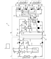
- FIG. 14 is a diagram for explaining the heating operation of the air conditioning device 10 according to the second embodiment.
- the solid arrows indicate the direction of the refrigerant flow
- the dashed arrows indicate the direction of the heat medium flow.
- the control device 5 switches the relay flow path switching device 302 to a direction that connects the relay heat exchanger 301 and the high-pressure main pipe 102.
- the control device 5 closes the relay switching valve 305.
- the control device 5 also opens the main expansion valve 303, opens the sub-expansion valve 304, and opens the outdoor expansion valve 24.
- the refrigerant sucked into the compressor 21 is compressed by the compressor 21 and discharged in a high-temperature, high-pressure gas state.
- the high-temperature, high-pressure gas refrigerant discharged from the compressor 21 passes through the high-pressure main pipe 102 via the outdoor pipe 115 provided with a check valve 26b, and flows into the relay unit 30.
- the refrigerant that flows into the relay unit 30 passes through the relay flow path switching device 302 and the refrigerant flow path 310 of the relay heat exchanger 301 via the inlet branch pipe 142.
- the refrigerant passing through the refrigerant flow path 310 of the relay heat exchanger 301 is cooled by heat exchange with the heat medium flowing through the heat medium flow path 311.
- the cooled refrigerant is decompressed and expanded by passing through a part of the outlet branch pipe 143 provided with the main expansion valve 303.
- the decompressed and expanded refrigerant passes through the low-pressure relay pipe 144 provided with the sub-expansion valve 304 and the low-pressure main pipe 101, and flows into the outdoor unit 2.
- the refrigerant that flows into the outdoor unit 2 passes through the outdoor expansion valve 24 via the outdoor piping 114 equipped with a check valve 26c, and is further decompressed and expanded before passing through the outdoor heat exchanger 23 that acts as an evaporator.
- the refrigerant that passes through the outdoor heat exchanger 23 exchanges heat with the outdoor air and evaporates and gasifies.
- the evaporated low-temperature, low-pressure gaseous refrigerant then passes through the outdoor flow switching device 22 and the accumulator 25, and is sucked back into the compressor 21 and circulated.
- the heat medium sent out from the pump 306 is heat exchanged with the refrigerant flowing through the refrigerant flow path 310 in the relay heat exchanger 301.
- the heat medium heated by the heat exchange passes through the high-pressure branch pipe 161 via the mixed flow three-way valve 307 and flows into the indoor unit 40.
- the heat medium that flows into the indoor unit 40 is cooled by heat exchange with the indoor air in the indoor heat medium heat exchanger 401. At this time, heating is performed indoors.
- the cooled refrigerant passes through the low-pressure branch pipe 162 and flows into the relay unit 30.
- the refrigerant that flows into the relay unit 30 passes through the diverting three-way valve 308, is sucked into the pump 306, and circulates.
- FIG 15 is a diagram for explaining the defrosting operation of the air conditioning apparatus 10 according to the second embodiment.
- the arrows indicate the direction of refrigerant flow
- the dashed arrows indicate the direction of heat medium flow.
- the control device 5 switches the outdoor flow path switching device 22 to a direction that connects the outdoor heat exchanger 23 and the accumulator 25.
- the control device 5 switches the relay flow path switching device 302 to a direction that connects the relay heat exchanger 301 and the high-pressure main pipe 102.
- the control device 5 opens the relay switching valve 305.
- the control device 5 also closes the main expansion valve 303, opens the sub-expansion valve 304, and opens the outdoor expansion valve 24.
- the refrigerant sucked into the compressor 21 is compressed by the compressor 21 and discharged in a high-temperature, high-pressure gas state.
- the high-temperature, high-pressure gas state refrigerant discharged from the compressor 21 passes through the high-pressure main pipe 102 via the outdoor pipe 115 provided with a check valve 26b, and flows into the relay unit 30.
- the refrigerant that flows into the relay unit 30 passes through a part of the high-pressure relay pipe 141 provided with a relay switching valve 305, the low-pressure relay pipe 144 provided with a sub-expansion valve 304, and the low-pressure main pipe 101, and flows back into the outdoor unit 2.
- the high-temperature, high-pressure gas state refrigerant that flows into the outdoor unit 2 passes through the outdoor expansion valve 24 via the outdoor pipe 114 provided with a check valve 26c, is decompressed and expanded, and passes through the outdoor heat exchanger 23.
- the high-temperature, low-pressure gas state refrigerant that passes through the outdoor heat exchanger 23 is heat exchanged with the frost attached to the outdoor heat exchanger 23, and becomes a low-temperature, low-pressure gas state.
- the outdoor heat exchanger 23 is defrosted.
- the low-temperature, low-pressure gaseous refrigerant then passes through the outdoor flow switching device 22 and the accumulator 25, and is again drawn into the compressor 21 and circulated.
- the refrigerant does not flow through the relay heat exchanger 301, so heat is not supplied to the indoor unit 40.
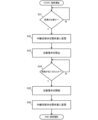
- FIG. 16 is a flowchart showing the operation of the control device 5 according to the second embodiment.
- the execution of the defrosting operation will be described with reference to FIG. 16.
- the control device 5 judges whether or not defrosting of the outdoor heat exchanger 23 is necessary based on the measurement result of the frost detection device 27 (step S31). If it is judged that defrosting of the outdoor heat exchanger 23 is unnecessary (step S31: NO), the process of step S31 is repeated until it is judged that defrosting of the outdoor heat exchanger 23 is necessary. If it is judged that defrosting of the outdoor heat exchanger 23 is necessary (step S31: YES), the relay switching valve 305 is changed to an open state (step S32). Then, the main expansion valve 303 is closed (step S33). This causes the operation mode to transition from the heating operation to the defrosting operation.
- step S34 determines whether the defrosting of the outdoor heat exchanger 23 has been completed based on the measurement result of the defrosting detection device 28 (step S34). If it is determined that the defrosting of the outdoor heat exchanger 23 is not completed (step S34: NO), the process of step S34 is repeated until it is determined that the defrosting of the outdoor heat exchanger 23 has been completed. If it is determined that the defrosting of the outdoor heat exchanger 23 has been completed (step S34: YES), the main expansion valve 303 is opened (step S35). Then, the relay switching valve 305 is changed to a closed state (step S36). This causes the operation mode to transition from the defrosting operation to the heating operation.
- the air conditioning device 10 of the second embodiment controls the relay unit 30 during defrost operation to cut off the supply of heat to the indoor unit 4, and controls the outdoor flow path switching device 22 to allow the refrigerant discharged from the compressor 21 to flow through the relay unit 30 without passing through the outdoor heat exchanger 23. Therefore, the outdoor unit 2, the relay unit 30, and the main pipe connecting the outdoor unit 2 and the relay unit 30 are prevented from dropping in temperature during defrost operation by circulating high-temperature refrigerant. In addition, the temperature of the indoor unit 40, in which refrigerant does not circulate, and the branch pipe connecting the relay unit 30 and the indoor unit 40 are also prevented from dropping during defrost operation.
- the air conditioning device 10 of the second embodiment it does not take time to reheat the outdoor unit 2, the relay unit 30, the indoor unit 40, and the main pipe and branch pipe when heating is resumed. Therefore, the heating resume time from the end of the defrost operation to the actual start of heating in the room can be shortened.
- Air conditioner 10 Air conditioner, 2 Outdoor unit, 3 Relay unit, 30 Relay unit, 4 Indoor unit, 40 Indoor unit, 4a First indoor unit, 4b Second indoor unit, 40a First indoor unit, 40b Second indoor unit, 5 Control device, 21 Compressor, 22 Outdoor flow path switching device, 23 Outdoor heat exchanger, 24 Outdoor expansion valve, 25 Accumulator, 2 6a check valve, 26b check valve, 26c check valve, 26d check valve, 27 frost detection device, 28 defrost detection device, 31 low pressure relay expansion valve, 32 high pressure relay expansion valve, 33 low pressure valve, 33a first low pressure valve, 33b second low pressure valve, 34 high pressure valve, 34a first high pressure valve, 34b second high pressure valve, 41 indoor refrigerant heat exchanger, 41a first indoor refrigerant medium heat exchanger, 41b second indoor refrigerant heat exchanger, 42 indoor expansion valve, 42a first indoor expansion valve, 42b second indoor expansion valve, 101 low pressure main pipe, 102 high pressure main pipe, 103 gas branch pipe, 103a first gas branch pipe,
Landscapes
- Engineering & Computer Science (AREA)
- Physics & Mathematics (AREA)
- Mechanical Engineering (AREA)
- Thermal Sciences (AREA)
- General Engineering & Computer Science (AREA)
- Air Conditioning Control Device (AREA)
- Compression-Type Refrigeration Machines With Reversible Cycles (AREA)
Abstract
This air conditioner comprises: an outdoor machine having a compressor that compresses a refrigerant, an outdoor channel switching device that switches the connection direction of a piping through which the refrigerant discharged from the compressor flows, an outdoor heat exchanger that exchanges heat between air and the refrigerant, and an outdoor expansion valve that expands the refrigerant; an indoor machine having an indoor refrigerant heat exchanger that exchanges heat between the refrigerant or a heat medium and air; a relay device that relays heat supplied via the refrigerant from the outdoor machine to the indoor machine via the refrigerant or the heat medium; and a control device. The control device executes a heating operation and a defrosting operation for removing frost stuck to the outdoor heat exchanger during the heating operation, and performs, during the defrosting operation, control on the relay device to cut off supplying of the heat to the indoor machine and control on the outdoor channel switching device to distribute the refrigerant discharged from the compressor to the relay device without passing through the outdoor heat exchanger.
Description
本開示は、中継機を有する空気調和装置に関する。
This disclosure relates to an air conditioning device having a repeater.
ヒートポンプ式の空気調和装置においては、低外気時に暖房を行う場合、室外熱交換器表面に霜が生じるため、定期的な霜取運転が必要となる。一般的に、霜取運転中に室外熱交換器で放熱した冷媒は低温となるため、冷媒回路において室外熱交換器の下流に位置する機器は冷媒に吸熱され温度が低下する。よって、霜取運転からの暖房復帰する際には、冷えた機器を再度加熱する必要があり、直ちに暖房が開始されず、室内において実際に暖房が開始されるまでの暖房復帰時間が長くなることがあった。
In heat pump air conditioners, when heating is performed when the outdoor air temperature is low, frost forms on the surface of the outdoor heat exchanger, making periodic defrosting operation necessary. Generally, the refrigerant that dissipates heat in the outdoor heat exchanger during defrosting operation becomes cold, so the temperature of the equipment located downstream of the outdoor heat exchanger in the refrigerant circuit drops as heat is absorbed by the refrigerant. Therefore, when returning to heating mode from defrosting operation, the cooled equipment needs to be heated again, so heating does not start immediately, and it can take a long time for heating to return to normal before heating actually starts indoors.
そこで、特許文献1には、霜取運転中に室外熱交換器で放熱し低温となった冷媒を、室外機、主管及び中継機のみで循環させ、枝管及び室内機に流さないように、弁の開閉及び向きを制御する、2管式冷暖同時運転システムを構成する空気調和装置が開示されている。特許文献1の空気調和装置では、霜取運転中、室外熱交換器で放熱し低温となった冷媒を、室外機、主管及び中継機のみで循環させ、中継機と室内機とを繋ぐ延長枝管及び室内機に流さないように、弁の開閉状態及び向きを制御する。これにより、特許文献1の空気調和装置は、延長枝管の温度低下を抑制して、暖房復帰時の延長枝管の再加熱を行う必要性をなくすことで、暖房復帰時間の短縮を図っている。
Patent Document 1 discloses an air conditioner constituting a two-pipe simultaneous heating and cooling operation system in which the refrigerant that has lost heat in the outdoor heat exchanger and become cold during defrosting operation is circulated only through the outdoor unit, main pipe, and relay unit, and the opening/closing state and direction of the valve are controlled so that the refrigerant that has lost heat in the outdoor heat exchanger and become cold is not allowed to flow into the branch pipes and indoor unit. In the air conditioner of Patent Document 1, the opening/closing state and direction of the valve are controlled so that the refrigerant that has lost heat in the outdoor heat exchanger and become cold is circulated only through the outdoor unit, main pipe, and relay unit, and is not allowed to flow into the extension branch pipe connecting the relay unit and the indoor unit, and into the indoor unit. In this way, the air conditioner of Patent Document 1 suppresses the temperature drop in the extension branch pipe, eliminating the need to reheat the extension branch pipe when heating is resumed, thereby shortening the time it takes to resume heating.
しかしながら、特許文献1では、室外機と中継機とを繋ぐ延長主管が低温冷媒に吸熱されて温度低下するため、暖房復帰時にこれらを再加熱する必要がある。したがって、特許文献1の空気調和装置においても、暖房復帰時間を更に短縮する余地が残されている。
However, in Patent Document 1, the extension main pipe connecting the outdoor unit and the relay unit loses temperature as heat is absorbed by the low-temperature refrigerant, and so it is necessary to reheat these pipes when heating is resumed. Therefore, even in the air conditioning device of Patent Document 1, there is still room to further shorten the heating resume time.
本開示は、上記のような課題を解決するためになされたもので、霜取運転からの暖房復帰時間が短縮された空気調和装置を提供することを目的とするものである。
This disclosure has been made to solve the problems described above, and aims to provide an air conditioner that shortens the time it takes to return to heating mode from defrosting operation.
本開示に係る空気調和装置は、冷媒を圧縮する圧縮機、圧縮機から吐出された冷媒が流れる配管の接続向きを切り替える室外流路切替装置、空気と冷媒との間で熱交換を行わせる室外熱交換器、及び冷媒を膨張させる室外膨張弁、を有する室外機と、冷媒又は熱媒体と、空気との間で熱交換を行わせる室内冷媒熱交換器を有する室内機と、室外機から冷媒を介して供給される温熱を、冷媒又は熱媒体を介して室内機に中継する中継機と、制御装置と、を備え、制御装置は、暖房運転、及び暖房運転中に室外熱交換器に着いた霜を除く霜取運転を実行し、霜取運転中に、中継機を制御して室内機への温熱の供給を遮断し、室外流路切替装置を制御して、圧縮機から吐出された冷媒を、室外熱交換器を経由させずに中継機に流通させる。
The air conditioner according to the present disclosure includes an outdoor unit having a compressor that compresses a refrigerant, an outdoor flow path switching device that switches the connection direction of the piping through which the refrigerant discharged from the compressor flows, an outdoor heat exchanger that performs heat exchange between the air and the refrigerant, and an outdoor expansion valve that expands the refrigerant, an indoor unit having an indoor refrigerant heat exchanger that performs heat exchange between the refrigerant or heat medium and the air, a relay unit that relays the heat supplied from the outdoor unit via the refrigerant to the indoor unit via the refrigerant or heat medium, and a control device, and the control device performs a heating operation and a defrosting operation that removes frost that has formed on the outdoor heat exchanger during the heating operation, controls the relay unit to cut off the supply of heat to the indoor unit during the defrosting operation, and controls the outdoor flow path switching device to circulate the refrigerant discharged from the compressor to the relay unit without passing through the outdoor heat exchanger.
本開示の空気調和装置は、霜取運転中に、中継機を制御して室内機への温熱の供給を遮断し、室外流路切替装置を制御して、圧縮機から吐出された冷媒を、室外熱交換器を経由させずに中継機に流通させる。このため、室外機、中継機、及び室外機と中継機とを繋ぐ主管は、高温の冷媒が循環することで、霜取運転中に温度が低下することが抑制されている。また、冷媒が循環しない室内機、及び中継機と室内機とを繋ぐ枝管の温度も霜取運転中に低下することが抑制されている。したがって、本開示の空気調和装置によれば、暖房復帰時に室外機、中継機、室内機、並びに主管及び枝管の再加熱に要する時間がかからず、霜取運転が終了してから室内において実際に暖房が開始されるまでの暖房復帰時間を短縮することができる。
During defrost operation, the air conditioning apparatus of the present disclosure controls the relay unit to cut off the supply of heat to the indoor unit, and controls the outdoor flow path switching device to allow the refrigerant discharged from the compressor to flow to the relay unit without passing through the outdoor heat exchanger. As a result, the outdoor unit, the relay unit, and the main pipe connecting the outdoor unit and the relay unit are prevented from dropping in temperature during defrost operation by circulating high-temperature refrigerant. In addition, the temperature of the indoor unit, in which refrigerant does not circulate, and the branch pipe connecting the relay unit and the indoor unit are also prevented from dropping during defrost operation. Therefore, according to the air conditioning apparatus of the present disclosure, it is not necessary to reheat the outdoor unit, the relay unit, the indoor unit, and the main pipe and branch pipe when heating is resumed, and the heating restoration time from the end of defrost operation to the actual start of heating in the room can be shortened.
以下、図面を参照して、実施の形態に係る空気調和装置について説明する。なお、図面において、同一の構成要素には同一符号を付して説明し、重複説明は必要な場合にのみ行なう。本開示は、以下の各実施の形態で説明する構成のうち、組合せ可能な構成のあらゆる組合せを含み得る。明細書全文に表わされている構成要素の形態は、あくまでも例示であって、明細書に記載された形態に限定するものではない。特に構成要素の組み合わせは、各実施の形態における組み合わせのみに限定するものではなく、他の実施の形態に記載した構成要素を別の実施の形態に適用することができる。
Below, an air conditioning device according to an embodiment will be described with reference to the drawings. In the drawings, identical components will be denoted with the same reference numerals and will be described only when necessary. This disclosure may include any combination of possible configurations among those described in the following embodiments. The configurations of the components shown in the entire specification are merely examples and are not limited to the configurations described in the specification. In particular, the combinations of the components are not limited to only the combinations in each embodiment, and components described in other embodiments may be applied to other embodiments.
実施の形態1.
図1は、実施の形態1に係る空気調和装置1の冷媒回路図である。図1に示すように、空気調和装置1は、室外機2、中継機3、第1室内機4a及び第2室内機4bを有する。Embodiment 1.
Fig. 1 is a refrigerant circuit diagram of anair conditioner 1 according to embodiment 1. As shown in Fig. 1, the air conditioner 1 has an outdoor unit 2, a relay unit 3, a first indoor unit 4a, and a second indoor unit 4b.
図1は、実施の形態1に係る空気調和装置1の冷媒回路図である。図1に示すように、空気調和装置1は、室外機2、中継機3、第1室内機4a及び第2室内機4bを有する。
Fig. 1 is a refrigerant circuit diagram of an
室外機2と中継機3とは、低圧主管101及び高圧主管102で接続される。低圧主管101には、中継機3から室外機2に流入する冷媒が通過する。高圧主管102には、室外機2から中継機3に流入する冷媒が通過する。高圧主管102には、低圧主管101を流れる冷媒よりも高圧の冷媒が流通する。
The outdoor unit 2 and the repeater unit 3 are connected by a low-pressure main pipe 101 and a high-pressure main pipe 102. Refrigerant flowing from the repeater unit 3 to the outdoor unit 2 passes through the low-pressure main pipe 101. Refrigerant flowing from the outdoor unit 2 to the repeater unit 3 passes through the high-pressure main pipe 102. Refrigerant with a higher pressure than the refrigerant flowing through the low-pressure main pipe 101 flows through the high-pressure main pipe 102.
中継機3と第1室内機4aとは、第1ガス枝管103a及び第1液枝管104aで接続される。中継機3と第2室内機4bとは、第2ガス枝管103b及び第2液枝管104bで接続される。第1ガス枝管103a及び第2ガス枝管103bには、空気調和装置1の運転モードによらずガス冷媒が流れる。第1液枝管104a及び第2液枝管104bには、空気調和装置1の運転モードによらず気液二相冷媒又は液冷媒が流れる。
The relay unit 3 and the first indoor unit 4a are connected by the first gas branch pipe 103a and the first liquid branch pipe 104a. The relay unit 3 and the second indoor unit 4b are connected by the second gas branch pipe 103b and the second liquid branch pipe 104b. Gas refrigerant flows through the first gas branch pipe 103a and the second gas branch pipe 103b regardless of the operation mode of the air conditioning device 1. Gas-liquid two-phase refrigerant or liquid refrigerant flows through the first liquid branch pipe 104a and the second liquid branch pipe 104b regardless of the operation mode of the air conditioning device 1.
室外機2は、第1室内機4a及び第2室内機4bに温熱又は冷熱を供給する機器である。室外機2は、室外配管111~115、吸入管116及び吐出管117を有する。室外機2は、圧縮機21、室外流路切替装置22、室外熱交換器23、室外膨張弁24、アキュムレータ25、逆止弁26a~26d、着霜検出装置27、及び除霜検出装置28を備える。
The outdoor unit 2 is a device that supplies hot or cold heat to the first indoor unit 4a and the second indoor unit 4b. The outdoor unit 2 has outdoor piping 111-115, a suction pipe 116, and a discharge pipe 117. The outdoor unit 2 includes a compressor 21, an outdoor flow path switching device 22, an outdoor heat exchanger 23, an outdoor expansion valve 24, an accumulator 25, check valves 26a-26d, a frost detection device 27, and a defrost detection device 28.
室外配管111は、室外流路切替装置22と低圧主管101とを接続する配管である。室外配管112は、室外流路切替装置22と、室外熱交換器23と、室外膨張弁24と、高圧主管102とを接続する配管である。室外配管113は、室外流路切替装置22とアキュムレータ25とを接続する配管である。室外配管114は、室外配管111と室外配管112とを接続する配管である。室外配管115は、室外配管111と室外配管112とを接続する配管である。吸入管116は、アキュムレータ25と圧縮機21の吸入側とを接続する配管である。吐出管117は、圧縮機21の吐出側と室外流路切替装置22とを接続する配管である。
The outdoor pipe 111 is a pipe that connects the outdoor flow path switching device 22 and the low pressure main pipe 101. The outdoor pipe 112 is a pipe that connects the outdoor flow path switching device 22, the outdoor heat exchanger 23, the outdoor expansion valve 24, and the high pressure main pipe 102. The outdoor pipe 113 is a pipe that connects the outdoor flow path switching device 22 and the accumulator 25. The outdoor pipe 114 is a pipe that connects the outdoor pipe 111 and the outdoor pipe 112. The outdoor pipe 115 is a pipe that connects the outdoor pipe 111 and the outdoor pipe 112. The suction pipe 116 is a pipe that connects the accumulator 25 and the suction side of the compressor 21. The discharge pipe 117 is a pipe that connects the discharge side of the compressor 21 and the outdoor flow path switching device 22.
圧縮機21は、低温且つ低圧の状態の冷媒を吸入し、吸入した冷媒を圧縮して高温且つ高圧の状態の冷媒にして吐出するものである。室外流路切替装置22は、例えば四方弁である。室外流路切替装置22は、圧縮機21から吐出された冷媒が流れる配管の接続向きを切り替える。具体的に、室外流路切替装置22は、配管の接続向きを、室外熱交換器23と圧縮機21とが接続する向きと、室外熱交換器23とアキュムレータ25とが接続する向きとに切り替える。これにより、冷媒回路における冷媒の流通方向が切り替わる。室外熱交換器23は、冷媒と室外空気との間で熱交換を行うものである。室外熱交換器23は、冷房運転時には放熱作用を有する凝縮器として機能し、暖房運転時には吸熱作用を有する蒸発器として機能する。室外膨張弁24は、冷媒を減圧して膨張させるものであり、例えば、開度が調整可能な電子膨張弁である。アキュムレータ25は、室外機2を循環する余剰冷媒を貯留するための機器である。
The compressor 21 sucks in a refrigerant in a low temperature and low pressure state, compresses the sucked refrigerant, and discharges it as a refrigerant in a high temperature and high pressure state. The outdoor flow path switching device 22 is, for example, a four-way valve. The outdoor flow path switching device 22 switches the connection direction of the pipe through which the refrigerant discharged from the compressor 21 flows. Specifically, the outdoor flow path switching device 22 switches the connection direction of the pipe between the connection direction of the outdoor heat exchanger 23 and the compressor 21 and the connection direction of the outdoor heat exchanger 23 and the accumulator 25. This switches the flow direction of the refrigerant in the refrigerant circuit. The outdoor heat exchanger 23 exchanges heat between the refrigerant and the outdoor air. The outdoor heat exchanger 23 functions as a condenser with a heat dissipation effect during cooling operation, and functions as an evaporator with a heat absorption effect during heating operation. The outdoor expansion valve 24 reduces the pressure of the refrigerant and expands it, and is, for example, an electronic expansion valve with an adjustable opening. The accumulator 25 is a device for storing excess refrigerant circulating through the outdoor unit 2.
逆止弁26aは、室外配管111において、室外配管114が接続する箇所と室外配管115が接続する箇所との間に設けられている。逆止弁26aは、室外配管111を低圧主管101から室外流路切替装置22に流れる冷媒の流通を許可し、室外流路切替装置22から低圧主管101に流れる冷媒の流通を遮断する。逆止弁26bは、室外配管115に設けられている。逆止弁26bは、室外配管115を室外配管111から室外配管112に流れる冷媒の流通を許可し、室外配管112から室外配管111に流れる冷媒の流通を遮断する。
Check valve 26a is provided in outdoor pipe 111 between the point where outdoor pipe 114 is connected and the point where outdoor pipe 115 is connected. Check valve 26a allows the flow of refrigerant flowing through outdoor pipe 111 from low-pressure main pipe 101 to outdoor flow path switching device 22, and blocks the flow of refrigerant flowing from outdoor flow path switching device 22 to low-pressure main pipe 101. Check valve 26b is provided in outdoor pipe 115. Check valve 26b allows the flow of refrigerant flowing through outdoor pipe 115 from outdoor pipe 111 to outdoor pipe 112, and blocks the flow of refrigerant flowing from outdoor pipe 112 to outdoor pipe 111.
逆止弁26cは、室外配管114に設けられている。逆止弁26cは、室外配管114を室外配管111から室外配管112に流れる冷媒の流通を許可し、室外配管112から室外配管111に流れる冷媒の流通を遮断する。逆止弁26dは、室外配管112において、室外配管114が接続する箇所と室外配管115が接続する箇所との間に設けられている。逆止弁26dは、室外配管112を室外膨張弁24から高圧主管102に流れる冷媒の流通を許可し、高圧主管102から室外膨張弁24に流れる冷媒の流通を遮断する。
Check valve 26c is provided in outdoor pipe 114. Check valve 26c allows the flow of refrigerant through outdoor pipe 114 from outdoor pipe 111 to outdoor pipe 112, and blocks the flow of refrigerant from outdoor pipe 112 to outdoor pipe 111. Check valve 26d is provided in outdoor pipe 112 between the point where outdoor pipe 114 is connected and the point where outdoor pipe 115 is connected. Check valve 26d allows the flow of refrigerant through outdoor pipe 112 from outdoor expansion valve 24 to high-pressure main pipe 102, and blocks the flow of refrigerant from high-pressure main pipe 102 to outdoor expansion valve 24.
中継機3は、室外機2から冷媒を介して供給される温熱又は冷熱を、冷媒又は熱媒体を介し第1室内機4a及び第2室内機4bに中継する機器である。また、中継機3は、室外機2からの第1室内機4a及び第2室内機4bへの冷媒又は熱媒体を介した温熱又は冷熱の供給を遮断する。中継機3は、液中継配管121、ガス中継配管124を有する。中継機3は、低圧中継膨張弁31、高圧中継膨張弁32、第1低圧弁33a、第2低圧弁33b、第1高圧弁34a、及び第2高圧弁34bを有する。
The relay unit 3 is a device that relays hot or cold energy supplied from the outdoor unit 2 via a refrigerant to the first indoor unit 4a and the second indoor unit 4b via the refrigerant or heat medium. The relay unit 3 also blocks the supply of hot or cold energy from the outdoor unit 2 to the first indoor unit 4a and the second indoor unit 4b via the refrigerant or heat medium. The relay unit 3 has a liquid relay pipe 121 and a gas relay pipe 124. The relay unit 3 has a low pressure relay expansion valve 31, a high pressure relay expansion valve 32, a first low pressure valve 33a, a second low pressure valve 33b, a first high pressure valve 34a, and a second high pressure valve 34b.
液中継配管121は、第1液枝管104a及び第2液枝管104bと、低圧主管101及び高圧主管102とを接続する。液中継配管121は、低圧側と高圧側とに分岐する配管であって、低圧液分岐管122及び高圧液分岐管123を有する。低圧液分岐管122は、液中継配管121の分岐部分と、低圧主管101とを接続する配管である。高圧液分岐管123は、液中継配管121の分岐部分と、高圧主管102とを接続する配管である。液中継配管121は、第1室内機4aと第2室内機4bとに対応して分岐している。
The liquid relay pipe 121 connects the first liquid branch pipe 104a and the second liquid branch pipe 104b to the low pressure main pipe 101 and the high pressure main pipe 102. The liquid relay pipe 121 is a pipe that branches into a low pressure side and a high pressure side, and has a low pressure liquid branch pipe 122 and a high pressure liquid branch pipe 123. The low pressure liquid branch pipe 122 is a pipe that connects the branched portion of the liquid relay pipe 121 to the low pressure main pipe 101. The high pressure liquid branch pipe 123 is a pipe that connects the branched portion of the liquid relay pipe 121 to the high pressure main pipe 102. The liquid relay pipe 121 branches corresponding to the first indoor unit 4a and the second indoor unit 4b.
ガス中継配管124は、第1ガス枝管103a及び第2ガス枝管103bと、低圧液分岐管122及び高圧液分岐管123とを接続している。ガス中継配管124は、低圧側と高圧側とに分岐する配管であって、低圧ガス分岐管125及び高圧ガス分岐管126を有する。低圧ガス分岐管125は、ガス中継配管124の分岐部分と、低圧液分岐管122とを接続する配管である。低圧ガス分岐管125は、第1室内機4aと第2室内機4bとに対応して分岐している。高圧ガス分岐管126は、ガス中継配管124の分岐部分と、高圧液分岐管123とを接続する配管である。高圧ガス分岐管126は、第1室内機4aと第2室内機4bとに対応して分岐している。
The gas relay pipe 124 connects the first gas branch pipe 103a and the second gas branch pipe 103b to the low-pressure liquid branch pipe 122 and the high-pressure liquid branch pipe 123. The gas relay pipe 124 is a pipe that branches into a low-pressure side and a high-pressure side, and has a low-pressure gas branch pipe 125 and a high-pressure gas branch pipe 126. The low-pressure gas branch pipe 125 is a pipe that connects the branched portion of the gas relay pipe 124 to the low-pressure liquid branch pipe 122. The low-pressure gas branch pipe 125 branches in correspondence with the first indoor unit 4a and the second indoor unit 4b. The high-pressure gas branch pipe 126 is a pipe that connects the branched portion of the gas relay pipe 124 to the high-pressure liquid branch pipe 123. The high-pressure gas branch pipe 126 branches in correspondence with the first indoor unit 4a and the second indoor unit 4b.
低圧中継膨張弁31は、低圧液分岐管122において、低圧ガス分岐管125の接続部分よりも液枝管104に近い部分に設けられている。低圧中継膨張弁31は、冷媒を減圧して膨張させるものであり、例えば、開度が調整可能な電子膨張弁である。高圧中継膨張弁32は、高圧液分岐管123において、高圧ガス分岐管126の接続部分よりも液枝管104に近い部分に設けられている。高圧中継膨張弁32は、冷媒を減圧して膨張させるものであり、例えば、開度が調整可能な電子膨張弁である。
The low-pressure relay expansion valve 31 is provided in the low-pressure liquid branch pipe 122 at a portion closer to the liquid branch pipe 104 than the connection portion of the low-pressure gas branch pipe 125. The low-pressure relay expansion valve 31 reduces the pressure of the refrigerant to expand it, and is, for example, an electronic expansion valve with an adjustable opening. The high-pressure relay expansion valve 32 is provided in the high-pressure liquid branch pipe 123 at a portion closer to the liquid branch pipe 104 than the connection portion of the high-pressure gas branch pipe 126. The high-pressure relay expansion valve 32 reduces the pressure of the refrigerant to expand it, and is, for example, an electronic expansion valve with an adjustable opening.
第1低圧弁33aは、第1室内機4aと第2室内機4bとに分岐する低圧ガス分岐管125のうち第1室内機4aに対応する位置に設けられる。第1低圧弁33aは、低圧ガス分岐管125のうち第1室内機4aに対応する領域を流れる冷媒の流通を許容する開状態と、低圧ガス分岐管125のうち第1室内機4aに対応する領域を流れる冷媒の流通を遮断する閉状態とを切り替える機能を有する。第2低圧弁33bは、第1室内機4aと第2室内機4bとに分岐する低圧ガス分岐管125のうち第2室内機4bに対応する位置に設けられる。第2低圧弁33bは、低圧ガス分岐管125のうち第2室内機4bに対応する領域を流れる冷媒の流通を許容する開状態と、低圧ガス分岐管125のうち第2室内機4bに対応する領域を流れる冷媒の流通を遮断する閉状態とを切り替える機能を有する。
The first low pressure valve 33a is provided at a position corresponding to the first indoor unit 4a in the low pressure gas branch pipe 125 that branches into the first indoor unit 4a and the second indoor unit 4b. The first low pressure valve 33a has a function of switching between an open state that allows the flow of refrigerant flowing through the region of the low pressure gas branch pipe 125 that corresponds to the first indoor unit 4a and a closed state that blocks the flow of refrigerant flowing through the region of the low pressure gas branch pipe 125 that corresponds to the first indoor unit 4a. The second low pressure valve 33b is provided at a position corresponding to the second indoor unit 4b in the low pressure gas branch pipe 125 that branches into the first indoor unit 4a and the second indoor unit 4b. The second low pressure valve 33b has a function of switching between an open state that allows the flow of refrigerant flowing through the region of the low pressure gas branch pipe 125 that corresponds to the second indoor unit 4b and a closed state that blocks the flow of refrigerant flowing through the region of the low pressure gas branch pipe 125 that corresponds to the second indoor unit 4b.
第1高圧弁34aは、第1室内機4aと第2室内機4bとに分岐する高圧ガス分岐管126のうち第1室内機4aに対応する位置に設けられる。第1高圧弁34aは、高圧ガス分岐管126のうち第1室内機4aに対応する領域を流れる冷媒の流通を許容する開状態と、高圧ガス分岐管126のうち第1室内機4aに対応する領域を流れる冷媒の流通を遮断する閉状態とを切り替える機能を有する。第2高圧弁34bは、第1室内機4aと第2室内機4bとに分岐する高圧ガス分岐管126のうち第2室内機4bに対応する位置に設けられる。第2高圧弁34bは、高圧ガス分岐管126のうち第2室内機4bに対応する領域を流れる冷媒の流通を許容する開状態と、高圧ガス分岐管126のうち第2室内機4bに対応する領域を流れる冷媒の流通を遮断する閉状態とを切り替える機能を有する。
The first high pressure valve 34a is provided at a position corresponding to the first indoor unit 4a in the high pressure gas branch pipe 126 that branches into the first indoor unit 4a and the second indoor unit 4b. The first high pressure valve 34a has a function of switching between an open state that allows the flow of refrigerant flowing through the area of the high pressure gas branch pipe 126 that corresponds to the first indoor unit 4a and a closed state that blocks the flow of refrigerant flowing through the area of the high pressure gas branch pipe 126 that corresponds to the first indoor unit 4a. The second high pressure valve 34b is provided at a position corresponding to the second indoor unit 4b in the high pressure gas branch pipe 126 that branches into the first indoor unit 4a and the second indoor unit 4b. The second high pressure valve 34b has a function of switching between an open state that allows the flow of refrigerant flowing through the area of the high pressure gas branch pipe 126 that corresponds to the second indoor unit 4b and a closed state that blocks the flow of refrigerant flowing through the area of the high pressure gas branch pipe 126 that corresponds to the second indoor unit 4b.
なお、第1低圧弁33a、第2低圧弁33b、第1高圧弁34a及び第2高圧弁34bは、冷媒の流通の許容及び遮断の切り替えができる機構でさえあれば、種類は限定されない。したがって、これらの弁は、例えば開閉弁又は膨張弁等であってもよい。
The first low pressure valve 33a, the second low pressure valve 33b, the first high pressure valve 34a, and the second high pressure valve 34b are not limited in type as long as they have a mechanism that can switch between allowing and blocking the flow of refrigerant. Therefore, these valves may be, for example, opening and closing valves or expansion valves.
第1室内機4a及び第2室内機4bは、室内に温熱又は冷熱を供給するための機器である。第1室内機4aは、第1室内冷媒配管131aを有する。第1室内機4aは、第1室内冷媒熱交換器41a及び第1室内膨張弁42aを備える。第1室内冷媒配管131aは、第1ガス枝管103aと、第1室内冷媒熱交換器41aと、第1室内膨張弁42aと、第1液枝管104aと、を接続し、内部を冷媒が流れる配管である。第2室内機4bは、第2室内冷媒配管131bを有する。第2室内機4bは、第2室内冷媒熱交換器41b及び第2室内膨張弁42bを備える。第2室内冷媒配管131bは、第2ガス枝管103bと、第2室内冷媒熱交換器41bと、第2室内膨張弁42bと、第2液枝管104bと、を接続し、内部を冷媒が流れる配管である。第1室内冷媒熱交換器41a及び第2室内冷媒熱交換器41bは、室内空気と冷媒との間で熱交換を行うものである。第1室内冷媒熱交換器41a及び第2室内冷媒熱交換器41bは、冷房運転時には蒸発器として作用し、暖房運転時には凝縮器として作用する。第1室内膨張弁42a及び第2室内膨張弁42bは、冷媒を減圧して膨張させるものであり、例えば、開度が調整可能な電子膨張弁である。
The first indoor unit 4a and the second indoor unit 4b are devices for supplying hot or cold heat to the room. The first indoor unit 4a has a first indoor refrigerant piping 131a. The first indoor unit 4a is equipped with a first indoor refrigerant heat exchanger 41a and a first indoor expansion valve 42a. The first indoor refrigerant piping 131a connects the first gas branch pipe 103a, the first indoor refrigerant heat exchanger 41a, the first indoor expansion valve 42a, and the first liquid branch pipe 104a, and is a pipe through which refrigerant flows. The second indoor unit 4b has a second indoor refrigerant piping 131b. The second indoor unit 4b is equipped with a second indoor refrigerant heat exchanger 41b and a second indoor expansion valve 42b. The second indoor refrigerant pipe 131b is a pipe that connects the second gas branch pipe 103b, the second indoor refrigerant heat exchanger 41b, the second indoor expansion valve 42b, and the second liquid branch pipe 104b, and through which the refrigerant flows. The first indoor refrigerant heat exchanger 41a and the second indoor refrigerant heat exchanger 41b exchange heat between the indoor air and the refrigerant. The first indoor refrigerant heat exchanger 41a and the second indoor refrigerant heat exchanger 41b act as evaporators during cooling operation and as condensers during heating operation. The first indoor expansion valve 42a and the second indoor expansion valve 42b reduce the pressure of the refrigerant to expand it, and are, for example, electronic expansion valves with adjustable opening.
空気調和装置1における室内機4は、2台である場合に限らず、1台又は3台以上であってもよい。以下の説明では、第1室内機4aと第2室内機4bとを特に区別しない場合、これら及びこれらに対応する構成を次のように呼称することがある。即ち、第1室内機4aと第2室内機4bとを区別しない場合、室内機44と称する。第1ガス枝管103aと第2ガス枝管103bとを区別しない場合、ガス枝管103と称する。第1液枝管104aと第2液枝管104bを区別しない場合、液枝管104と称する。第1低圧弁33aと第2低圧弁33bとを区別しない場合、低圧弁33と称する。第1高圧弁34aと第2高圧弁34bと区別しない場合、高圧弁34と称する。第1室内冷媒熱交換器41aと第2室内冷媒熱交換器41bとを区別しない場合、室内冷媒熱交換器41と称する。第1室内膨張弁42aと第2室内膨張弁42bとを区別しない場合、室内膨張弁42と称する。
The number of indoor units 4 in the air conditioning device 1 is not limited to two, and may be one, three or more. In the following description, when the first indoor unit 4a and the second indoor unit 4b are not particularly distinguished, they and their corresponding configurations may be referred to as follows. That is, when the first indoor unit 4a and the second indoor unit 4b are not distinguished, they are referred to as indoor units 44. When the first gas branch pipe 103a and the second gas branch pipe 103b are not distinguished, they are referred to as gas branch pipe 103. When the first liquid branch pipe 104a and the second liquid branch pipe 104b are not distinguished, they are referred to as liquid branch pipe 104. When the first low pressure valve 33a and the second low pressure valve 33b are not distinguished, they are referred to as low pressure valve 33. When the first high pressure valve 34a and the second high pressure valve 34b are not distinguished, they are referred to as high pressure valve 34. When the first indoor refrigerant heat exchanger 41a and the second indoor refrigerant heat exchanger 41b are not differentiated from each other, they are referred to as the indoor refrigerant heat exchanger 41. When the first indoor expansion valve 42a and the second indoor expansion valve 42b are not differentiated from each other, they are referred to as the indoor expansion valve 42.
空気調和装置1は、室外機2、中継機3及び室内機4が有する各機器を制御する制御装置5を有する。制御装置5は、各種の運転モードの実行を制御する。実施の形態1の空気調和装置1で実行される運転モードには、暖房運転、霜取運転、及び冷房運転がある。暖房運転及び冷房運転は、図示しないリモコン等から利用者によって実行が指示される。霜取運転は、暖房運転時に室外熱交換器23に着いた霜を除くための運転モードである。
The air conditioning device 1 has a control device 5 that controls each device of the outdoor unit 2, relay unit 3, and indoor unit 4. The control device 5 controls the execution of various operation modes. The operation modes executed by the air conditioning device 1 of embodiment 1 include heating operation, defrosting operation, and cooling operation. The user instructs the execution of heating operation and cooling operation using a remote control (not shown) or the like. The defrosting operation is an operation mode for removing frost that has formed on the outdoor heat exchanger 23 during heating operation.
ここで、制御装置5のハードウェアの一例を説明する。図2は、実施の形態1に係る制御装置5の一構成例を示すハードウェア構成図である。制御装置5の各機能がハードウェアで実行される場合、制御装置5は、図2に示すように処理回路201で構成される。処理回路201は、例えば、単一回路、複合回路、プログラム化したプロセッサ202、並列プログラム化したプロセッサ202、ASIC(Application Specific Integrated Circuit)、FPGA(Field-Programmable Gate Array)、又はこれらを組み合わせたものである。処理回路201が実現する各機能のそれぞれを、個別のハードウェアで実現してもよいし、各機能が一つのハードウェアで実現されてもよい。
Here, an example of the hardware of the control device 5 will be described. FIG. 2 is a hardware configuration diagram showing an example of the configuration of the control device 5 according to the first embodiment. When each function of the control device 5 is executed by hardware, the control device 5 is configured by a processing circuit 201 as shown in FIG. 2. The processing circuit 201 is, for example, a single circuit, a composite circuit, a programmed processor 202, a parallel programmed processor 202, an ASIC (Application Specific Integrated Circuit), an FPGA (Field-Programmable Gate Array), or a combination of these. Each function realized by the processing circuit 201 may be realized by separate hardware, or each function may be realized by a single piece of hardware.
また、制御装置5の別のハードウェアの一例を説明する。図3は、実施の形態1に係る制御装置5の一構成例を示すハードウェア構成図である。制御装置5の各機能がソフトウェアで実行される場合、制御装置5は、図3に示すように、CPU等のプロセッサ202及びメモリ203で構成される。図3は、プロセッサ202及びメモリ203が互いにバス204を介して通信可能に接続されることを示している。制御装置5の各機能は、ソフトウェア、ファームウェア、又はソフトウェアとファームウェアとの組み合わせにより実現される。ソフトウェア及びファームウェアは、プログラムとして記述され、メモリ203に格納される。プロセッサ202は、メモリ203に記憶されたプログラムを読み出して実行することにより、各手段の機能を実現する。
Furthermore, another example of hardware of the control device 5 will be described. FIG. 3 is a hardware configuration diagram showing an example of the configuration of the control device 5 according to the first embodiment. When each function of the control device 5 is executed by software, the control device 5 is composed of a processor 202 such as a CPU and a memory 203, as shown in FIG. 3. FIG. 3 shows that the processor 202 and the memory 203 are communicatively connected to each other via a bus 204. Each function of the control device 5 is realized by software, firmware, or a combination of software and firmware. The software and firmware are written as programs and stored in the memory 203. The processor 202 realizes the functions of each means by reading and executing the programs stored in the memory 203.
メモリ203として、例えば、ROM(Read Only Memory)、フラッシュメモリ、EPROM(Erasable and Programmable ROM)及びEEPROM(Electrically Erasable and Programmable ROM)等の不揮発性の半導体メモリが用いられる。また、メモリ203として、RAM(Random Access Memory)の揮発性の半導体メモリが用いられてもよい。さらに、メモリ203として、磁気ディスク、フレキシブルディスク、光ディスク、CD(Compact Disc)、MD(Mini Disc)及びDVD(Digital Versatile Disc)等の着脱可能な記録媒体が用いられてもよい。なお、処理回路201の機能の一部を専用のハードウェアで実現し、一部をソフトウェア又はファームウェアで実現するようにしてもよい。
As the memory 203, for example, a non-volatile semiconductor memory such as a ROM (Read Only Memory), a flash memory, an EPROM (Erasable and Programmable ROM), and an EEPROM (Electrically Erasable and Programmable ROM) may be used. Also, a volatile semiconductor memory such as a RAM (Random Access Memory) may be used as the memory 203. Furthermore, a removable recording medium such as a magnetic disk, a flexible disk, an optical disk, a CD (Compact Disc), an MD (Mini Disc), and a DVD (Digital Versatile Disc) may be used as the memory 203. In addition, some of the functions of the processing circuit 201 may be realized by dedicated hardware, and some may be realized by software or firmware.
図4は、実施の形態1に係る空気調和装置1を示す機能ブロック図である。図4に示すように、制御装置5は、運転モードに応じて、室外機2の圧縮機21、室外流路切替装置22、及び室外膨張弁24を制御する。また、制御装置5は、運転モードに応じて、中継機3の低圧中継膨張弁31、高圧中継膨張弁32、低圧弁33及び高圧弁34を制御する。さらに、制御装置5は、運転モードに応じて、室内機44の室内膨張弁42を制御する。
FIG. 4 is a functional block diagram showing the air conditioning apparatus 1 according to the first embodiment. As shown in FIG. 4, the control device 5 controls the compressor 21, outdoor flow path switching device 22, and outdoor expansion valve 24 of the outdoor unit 2 according to the operation mode. The control device 5 also controls the low pressure relay expansion valve 31, high pressure relay expansion valve 32, low pressure valve 33, and high pressure valve 34 of the relay unit 3 according to the operation mode. Furthermore, the control device 5 controls the indoor expansion valve 42 of the indoor unit 44 according to the operation mode.
制御装置5は、着霜検出装置27及び除霜検出装置28の測定結果に基づいて、運転モードを遷移させる。着霜検出装置27は、室外熱交換器23への着霜を検出するためのセンサであって、例えば圧力センサである。着霜検出装置27は、特に限定されないが、例えば、室外熱交換器23と圧縮機21との間の配管に配置する。着霜検出装置27は、測定結果を制御装置5に送信する。制御装置5は、着霜検出装置27の測定結果に基づいて、室外熱交換器23に除霜を要する程度の霜が発生していると判断した場合、運転モードを暖房運転から霜取運転に遷移させる。例えば、制御装置5は、着霜検出装置27が測定した冷媒の圧力が予め定められた閾値に満たない場合、室外熱交換器23に除霜を要する程度の霜が発生していると判断する。除霜検出手段は、室外熱交換器23からの除霜を検出するためのセンサであって、例えば温度センサである。除霜検出装置28は、室外熱交換器23から圧縮機21の間の配管に配置する。除霜検出装置28は、測定結果を制御装置5に送信する。制御装置5は、除霜検出装置28の測定結果に基づいて、室外熱交換器23の除霜が完了されたと判断した場合、運転モードを霜取運転から暖房運転に遷移させる。例えば、制御装置5は、除霜検出装置28が測定した冷媒の温度が予め定められた閾値を超える場合、室外熱交換器23の除霜が完了されたと判断する。
The control device 5 transitions the operation mode based on the measurement results of the frost detection device 27 and the defrost detection device 28. The frost detection device 27 is a sensor for detecting frost on the outdoor heat exchanger 23, and is, for example, a pressure sensor. The frost detection device 27 is not particularly limited, but is, for example, arranged in the piping between the outdoor heat exchanger 23 and the compressor 21. The frost detection device 27 transmits the measurement result to the control device 5. When the control device 5 determines, based on the measurement result of the frost detection device 27, that frost has occurred in the outdoor heat exchanger 23 to the extent that defrosting is required, the control device 5 transitions the operation mode from heating operation to defrosting operation. For example, when the pressure of the refrigerant measured by the frost detection device 27 does not meet a predetermined threshold value, the control device 5 determines that frost has occurred in the outdoor heat exchanger 23 to the extent that defrosting is required. The defrost detection means is a sensor for detecting defrost from the outdoor heat exchanger 23, and is, for example, a temperature sensor. The defrost detection device 28 is arranged in the piping between the outdoor heat exchanger 23 and the compressor 21. The defrost detection device 28 transmits the measurement result to the control device 5. When the control device 5 determines that the defrosting of the outdoor heat exchanger 23 is completed based on the measurement result of the defrost detection device 28, it transitions the operation mode from the defrosting operation to the heating operation. For example, when the temperature of the refrigerant measured by the defrost detection device 28 exceeds a predetermined threshold, the control device 5 determines that the defrosting of the outdoor heat exchanger 23 is completed.
暖房運転及び霜取運転における各機器の状態と、冷媒の流れについて説明する。冷房運転については、周知の形態と同様であるため、説明を省略する。まず、暖房運転について説明する。図5は、実施の形態1に係る空気調和装置1の暖房運転を説明するための図である。図5において、矢印は冷媒の流れの方向を示す。暖房運転を行う場合、制御装置5は、室外流路切替装置22を室外熱交換器23とアキュムレータ25とを繋ぐ向きに切り替える。また、制御装置5は、低圧中継膨張弁31を開放し、高圧中継膨張弁32を閉止する。さらに、制御装置5は、低圧弁33を閉状態にし、高圧弁34を開状態にする。そして、制御装置5は、室内膨張弁42及び室外膨張弁24を開放する。
The state of each device and the flow of refrigerant during heating operation and defrosting operation will be described. The cooling operation is similar to that of the known embodiment, so a description will be omitted. First, the heating operation will be described. FIG. 5 is a diagram for explaining the heating operation of the air conditioner 1 according to the first embodiment. In FIG. 5, the arrows indicate the direction of the refrigerant flow. When performing the heating operation, the control device 5 switches the outdoor flow path switching device 22 to a direction that connects the outdoor heat exchanger 23 and the accumulator 25. The control device 5 also opens the low-pressure relay expansion valve 31 and closes the high-pressure relay expansion valve 32. Furthermore, the control device 5 closes the low-pressure valve 33 and opens the high-pressure valve 34. The control device 5 then opens the indoor expansion valve 42 and the outdoor expansion valve 24.
暖房運転において、圧縮機21に吸入された冷媒は、圧縮機21によって圧縮されて高温かつ高圧のガス状態で吐出される。圧縮機21から吐出された高温かつ高圧のガス状態の冷媒は、逆止弁26bが設けられた室外配管115を経由して高圧主管102を通過し、中継機3に流入する。中継機3に流入した冷媒は、高圧液分岐管123の一部、高圧弁34が設けられた高圧ガス分岐管126、及びガス枝管103を通過して、室内機4に流入する。室内機4に流入した高温かつ高圧のガス状態の冷媒は、凝縮器として作用する室内冷媒熱交換器41を通過する。室内冷媒熱交換器41を通過する冷媒は、室内空気と熱交換されて凝縮し、液化する。この際に、室内空気が温められて、室内における暖房が実施される。液状態の冷媒は、室内膨張弁42を通過し、減圧及び膨張されて、低温且つ低圧の気液二相状態の冷媒となる。気液二相状態の冷媒は、液枝管104を通過して、中継機3に流入する。中継機3に流入した冷媒は、低圧中継膨張弁31が設けられた低圧液分岐管122、及び低圧主管101を通過して、室外機2に流入する。室外機2に流入した冷媒は、逆止弁26cが設けられた室外配管114を経由して室外膨張弁24を通過し、さらに減圧及び膨張されて、蒸発器として作用する室外熱交換器23を通過する。室外熱交換器23を通過する冷媒は、室外空気と熱交換されて蒸発し、ガス化する。その後、蒸発した低温且つ低圧のガス状態の冷媒は、室外流路切替装置22及びアキュムレータ25を通過して、再び圧縮機21に吸入され、循環する。
In heating operation, the refrigerant sucked into the compressor 21 is compressed by the compressor 21 and discharged in a high-temperature, high-pressure gas state. The high-temperature, high-pressure gas refrigerant discharged from the compressor 21 passes through the high-pressure main pipe 102 via the outdoor piping 115 equipped with a check valve 26b, and flows into the relay unit 3. The refrigerant that flows into the relay unit 3 passes through a part of the high-pressure liquid branch pipe 123, the high-pressure gas branch pipe 126 equipped with a high-pressure valve 34, and the gas branch pipe 103, and flows into the indoor unit 4. The high-temperature, high-pressure gas refrigerant that flows into the indoor unit 4 passes through the indoor refrigerant heat exchanger 41, which acts as a condenser. The refrigerant that passes through the indoor refrigerant heat exchanger 41 exchanges heat with the indoor air, condenses, and liquefies. At this time, the indoor air is warmed, and heating is performed in the room. The liquid refrigerant passes through the indoor expansion valve 42, is decompressed and expanded, and becomes a low-temperature, low-pressure gas-liquid two-phase refrigerant. The refrigerant in the gas-liquid two-phase state passes through the liquid branch pipe 104 and flows into the relay unit 3. The refrigerant that flows into the relay unit 3 passes through the low-pressure liquid branch pipe 122, which is provided with the low-pressure relay expansion valve 31, and the low-pressure main pipe 101, and flows into the outdoor unit 2. The refrigerant that flows into the outdoor unit 2 passes through the outdoor expansion valve 24 via the outdoor piping 114, which is provided with the check valve 26c, and is further reduced in pressure and expanded, and passes through the outdoor heat exchanger 23, which acts as an evaporator. The refrigerant that passes through the outdoor heat exchanger 23 exchanges heat with the outdoor air and evaporates and gasifies. The evaporated low-temperature, low-pressure gaseous refrigerant then passes through the outdoor flow switching device 22 and the accumulator 25, and is sucked back into the compressor 21 and circulates.
次に、霜取運転について説明する。図6は、実施の形態1に係る空気調和装置1の霜取運転を説明するための図である。図6において、矢印は冷媒の流れの方向を示す。霜取運転を行う場合、制御装置5は、室外流路切替装置22を室外熱交換器23とアキュムレータ25とを繋ぐ向きに切り替える。また、制御装置5は、低圧中継膨張弁31を閉止し、高圧中継膨張弁32を閉止する。さらに、制御装置5は、低圧弁33を開状態にし、高圧弁34を開状態にする。そして、制御装置5は、室内膨張弁42を開放し、室外膨張弁24を開放する。なお、室内膨張弁42は、閉止してもよい。
Next, the defrosting operation will be described. Figure 6 is a diagram for explaining the defrosting operation of the air conditioning apparatus 1 according to the first embodiment. In Figure 6, the arrows indicate the direction of refrigerant flow. When performing the defrosting operation, the control device 5 switches the outdoor flow path switching device 22 to a direction that connects the outdoor heat exchanger 23 and the accumulator 25. The control device 5 also closes the low pressure relay expansion valve 31 and closes the high pressure relay expansion valve 32. Furthermore, the control device 5 opens the low pressure valve 33 and opens the high pressure valve 34. The control device 5 then opens the indoor expansion valve 42 and opens the outdoor expansion valve 24. Note that the indoor expansion valve 42 may be closed.
霜取運転において、圧縮機21に吸入された冷媒は、圧縮機21によって圧縮されて高温かつ高圧のガス状態で吐出される。圧縮機21から吐出された高温かつ高圧のガス状態の冷媒は、逆止弁26bが設けられた室外配管115を経由して高圧主管102を通過し、中継機3に流入する。中継機3に流入した冷媒は、高圧液分岐管123の一部、高圧弁34が設けられた高圧ガス分岐管126、低圧弁33が設けられた低圧ガス分岐管125、低圧液分岐管122の一部、及び低圧主管101を通り、再び室外機2に流入する。室外機2に流入した高温かつ高圧のガス状態の冷媒は、逆止弁26cが設けられた室外配管114を経由して室外膨張弁24を通過して減圧及び膨張され、高温かつ低圧のガス状態の冷媒となって、室外熱交換器23を通過する。室外熱交換器23を通過する高温かつ低圧のガス状態の冷媒は、室外熱交換器23に付着した霜と熱交換されて、低温かつ低圧のガス状態となる。この際に、室外熱交換器23が除霜される。その後、低温かつ低圧のガス状態の冷媒は、室外流路切替装置22、及びアキュムレータ25を通過して、再び圧縮機21に吸入され、循環する。このように、実施の形態1の霜取運転においては、室外機2と中継機3との間で高温の冷媒が循環し、室内機44への冷媒の流通、延いては温熱の供給は遮断されている。
During defrost operation, the refrigerant sucked into the compressor 21 is compressed by the compressor 21 and discharged in a high-temperature, high-pressure gas state. The high-temperature, high-pressure gas refrigerant discharged from the compressor 21 passes through the high-pressure main pipe 102 via the outdoor piping 115 equipped with a check valve 26b, and flows into the relay unit 3. The refrigerant that flows into the relay unit 3 passes through a part of the high-pressure liquid branch pipe 123, the high-pressure gas branch pipe 126 equipped with a high-pressure valve 34, the low-pressure gas branch pipe 125 equipped with a low-pressure valve 33, a part of the low-pressure liquid branch pipe 122, and the low-pressure main pipe 101, and flows back into the outdoor unit 2. The high-temperature, high-pressure gas refrigerant that flows into the outdoor unit 2 passes through the outdoor expansion valve 24 via the outdoor piping 114 equipped with a check valve 26c, where it is decompressed and expanded, becoming a high-temperature, low-pressure gas refrigerant, which passes through the outdoor heat exchanger 23. The high-temperature, low-pressure gaseous refrigerant passing through the outdoor heat exchanger 23 exchanges heat with the frost adhering to the outdoor heat exchanger 23, and becomes a low-temperature, low-pressure gaseous refrigerant. At this time, the outdoor heat exchanger 23 is defrosted. The low-temperature, low-pressure gaseous refrigerant then passes through the outdoor flow switching device 22 and the accumulator 25, and is again sucked into the compressor 21 and circulated. In this way, in the defrosting operation of the first embodiment, high-temperature refrigerant circulates between the outdoor unit 2 and the relay unit 3, and the flow of refrigerant to the indoor unit 44, and thus the supply of heat, is blocked.
制御装置5の動作について説明する。図7は、実施の形態1に係る制御装置5の動作を示すフローチャートである。図7に基づいて、除霜運転の実行について説明する。制御装置5は、暖房運転中に、着霜検出装置27の測定結果に基づいて、室外熱交換器23の除霜が必要であるか否かを判断する(ステップS1)。室外熱交換器23の除霜が不要であると判定された場合(ステップS1:NO)、室外熱交換器23の除霜が必要であると判定されるまでステップS1の処理を繰り返す。室外熱交換器23の除霜が必要であると判定された場合(ステップS1:YES)、低圧弁33を開状態に変更する(ステップS2)。その後、低圧中継膨張弁31を閉止する(ステップS3)。これにより、運転モードが暖房運転から霜取運転に移行する。
The operation of the control device 5 will be described. FIG. 7 is a flowchart showing the operation of the control device 5 according to the first embodiment. The execution of the defrosting operation will be described with reference to FIG. 7. During the heating operation, the control device 5 determines whether or not defrosting of the outdoor heat exchanger 23 is necessary based on the measurement result of the frost detection device 27 (step S1). If it is determined that defrosting of the outdoor heat exchanger 23 is unnecessary (step S1: NO), the process of step S1 is repeated until it is determined that defrosting of the outdoor heat exchanger 23 is necessary. If it is determined that defrosting of the outdoor heat exchanger 23 is necessary (step S1: YES), the low-pressure valve 33 is changed to an open state (step S2). Then, the low-pressure relay expansion valve 31 is closed (step S3). This causes the operation mode to transition from the heating operation to the defrosting operation.
制御装置5は、霜取運転中に、除霜検出装置28の測定結果に基づいて、室外熱交換器23の除霜が完了されたか否かを判断する(ステップS4)。室外熱交換器23の除霜が未完了であると判定された場合(ステップS4:NO)、室外熱交換器23の除霜が完了されたと判定されるまでステップS4の処理を繰り返す。室外熱交換器23の除霜が完了されたと判定された場合(ステップS4:YES)、低圧中継膨張弁31を開放する(ステップS5)。その後、低圧弁33を閉状態に変更する(ステップS6)。これにより、運転モードが霜取運転から暖房運転に移行する。
During the defrosting operation, the control device 5 determines whether the defrosting of the outdoor heat exchanger 23 has been completed based on the measurement result of the defrosting detection device 28 (step S4). If it is determined that the defrosting of the outdoor heat exchanger 23 is not completed (step S4: NO), the process of step S4 is repeated until it is determined that the defrosting of the outdoor heat exchanger 23 has been completed. If it is determined that the defrosting of the outdoor heat exchanger 23 has been completed (step S4: YES), the low-pressure relay expansion valve 31 is opened (step S5). Then, the low-pressure valve 33 is changed to a closed state (step S6). This causes the operation mode to transition from the defrosting operation to the heating operation.
以上のように、実施の形態1の空気調和装置1は、霜取運転中に、中継機3を制御して室内機4への温熱の供給を遮断し、室外流路切替装置22を制御して、圧縮機21から吐出された冷媒を、室外熱交換器23を経由させずに中継機3に流通させる。このため、室外機2、中継機3、及び室外機2と中継機3とを繋ぐ主管は、高温の冷媒が循環することで、霜取運転中に温度が低下することが抑制されている。また、冷媒が循環しない室内機4、及び中継機3と室内機4とを繋ぐ枝管の温度も霜取運転中に低下することが抑制されている。したがって、実施の形態1の空気調和装置1によれば、暖房復帰時に室外機2、中継機3、室内機4、並びに主管及び枝管の再加熱に要する時間がかからず、霜取運転が終了してから室内において実際に暖房が開始されるまでの暖房復帰時間を短縮することができる。
As described above, the air conditioning device 1 of the first embodiment controls the relay unit 3 to cut off the supply of heat to the indoor unit 4 during defrost operation, and controls the outdoor flow path switching device 22 to allow the refrigerant discharged from the compressor 21 to flow to the relay unit 3 without passing through the outdoor heat exchanger 23. Therefore, the outdoor unit 2, the relay unit 3, and the main pipe connecting the outdoor unit 2 and the relay unit 3 are prevented from dropping in temperature during defrost operation by circulating high-temperature refrigerant. In addition, the temperature of the indoor unit 4, in which refrigerant does not circulate, and the branch pipe connecting the relay unit 3 and the indoor unit 4 are also prevented from dropping during defrost operation. Therefore, according to the air conditioning device 1 of the first embodiment, it is not necessary to reheat the outdoor unit 2, the relay unit 3, the indoor unit 4, and the main pipe and branch pipe when heating is resumed, and the heating resume time from the end of the defrost operation to the start of actual heating in the room can be shortened.
(実施の形態1の変形例1)
空気調和装置1は、霜取運転において、実施の形態1で示した霜取運転での機器の制御とは異なる機器の制御を行うようにしてもよい。図8は、実施の形態1の変形例1に係る空気調和装置1の除霜運転を説明するための冷媒回路図である。図8において、矢印は冷媒の流れの方向を示す。霜取運転を行う場合、制御装置5は、室外流路切替装置22を室外熱交換器23とアキュムレータ25とを繋ぐ向きに切り替える。また、制御装置5は、低圧中継膨張弁31を開放し、高圧中継膨張弁32を開放する。さらに、制御装置5は、低圧弁33を閉状態にし、高圧弁34を開状態にする。そして、制御装置5は、室内膨張弁42を閉止し、室外膨張弁24を開放する。 (First Modification of First Embodiment)
In the defrosting operation, theair conditioner 1 may control devices different from those in the defrosting operation shown in the first embodiment. FIG. 8 is a refrigerant circuit diagram for explaining the defrosting operation of the air conditioner 1 according to the first modification of the first embodiment. In FIG. 8, the arrows indicate the direction of the refrigerant flow. When performing the defrosting operation, the control device 5 switches the outdoor flow path switching device 22 to a direction that connects the outdoor heat exchanger 23 and the accumulator 25. In addition, the control device 5 opens the low pressure relay expansion valve 31 and opens the high pressure relay expansion valve 32. Furthermore, the control device 5 closes the low pressure valve 33 and opens the high pressure valve 34. Then, the control device 5 closes the indoor expansion valve 42 and opens the outdoor expansion valve 24.
空気調和装置1は、霜取運転において、実施の形態1で示した霜取運転での機器の制御とは異なる機器の制御を行うようにしてもよい。図8は、実施の形態1の変形例1に係る空気調和装置1の除霜運転を説明するための冷媒回路図である。図8において、矢印は冷媒の流れの方向を示す。霜取運転を行う場合、制御装置5は、室外流路切替装置22を室外熱交換器23とアキュムレータ25とを繋ぐ向きに切り替える。また、制御装置5は、低圧中継膨張弁31を開放し、高圧中継膨張弁32を開放する。さらに、制御装置5は、低圧弁33を閉状態にし、高圧弁34を開状態にする。そして、制御装置5は、室内膨張弁42を閉止し、室外膨張弁24を開放する。 (First Modification of First Embodiment)
In the defrosting operation, the
霜取運転において、圧縮機21に吸入された冷媒は、圧縮機21によって圧縮されて高温かつ高圧のガス状態で吐出される。圧縮機21から吐出された高温かつ高圧のガス状態の冷媒は、逆止弁26bが設けられた室外配管115を経由して高圧主管102を通過し、中継機3に流入する。中継機3に流入した冷媒は、高圧中継膨張弁32が設けられた高圧液分岐管123、低圧中継膨張弁31が設けられた低圧液分岐管122、及び低圧主管101を通り、再び室外機2に流入する。室外機2に流入した高温かつ高圧のガス状態の冷媒は、逆止弁26cが設けられた室外配管114を経由して室外膨張弁24を通過して減圧及び膨張され、高温かつ低圧のガス状態の冷媒となって、室外熱交換器23を通過する。室外熱交換器23を通過する高温かつ低圧のガス状態の冷媒は、室外熱交換器23に付着した霜と熱交換されて、低温かつ低圧のガス状態となる。この際に、室外熱交換器23が除霜される。その後、低温かつ低圧のガス状態の冷媒は、室外流路切替装置22、及びアキュムレータ25を通過して、再び圧縮機21に吸入され、循環する。このように、実施の形態1の変形例1の霜取運転においても、室外機2と中継機3との間で高温の冷媒が循環し、室内機44への冷媒の流通、延いては温熱の供給は遮断されている。
During defrost operation, the refrigerant sucked into the compressor 21 is compressed by the compressor 21 and discharged in a high-temperature, high-pressure gas state. The high-temperature, high-pressure gas state refrigerant discharged from the compressor 21 passes through the high-pressure main pipe 102 via the outdoor piping 115 equipped with a check valve 26b, and flows into the relay unit 3. The refrigerant that flows into the relay unit 3 passes through the high-pressure liquid branch pipe 123 equipped with a high-pressure relay expansion valve 32, the low-pressure liquid branch pipe 122 equipped with a low-pressure relay expansion valve 31, and the low-pressure main pipe 101, and flows back into the outdoor unit 2. The high-temperature, high-pressure gas state refrigerant that flows into the outdoor unit 2 passes through the outdoor expansion valve 24 via the outdoor piping 114 equipped with a check valve 26c, where it is decompressed and expanded, becoming a high-temperature, low-pressure gas state refrigerant that passes through the outdoor heat exchanger 23. The high-temperature, low-pressure gaseous refrigerant passing through the outdoor heat exchanger 23 exchanges heat with the frost adhering to the outdoor heat exchanger 23, and becomes a low-temperature, low-pressure gaseous state. At this time, the outdoor heat exchanger 23 is defrosted. The low-temperature, low-pressure gaseous refrigerant then passes through the outdoor flow path switching device 22 and the accumulator 25, and is again sucked into the compressor 21 and circulated. In this way, even in the defrosting operation of the first modification of the first embodiment, high-temperature refrigerant circulates between the outdoor unit 2 and the relay unit 3, and the flow of refrigerant to the indoor unit 44, and the supply of heat, are blocked.
制御装置5の動作について説明する。図9は、実施の形態1の変形例1に係る制御装置5の動作を示すフローチャートである。図9に基づいて、除霜運転の実行について説明する。制御装置5は、暖房運転中に、着霜検出装置27の測定結果に基づいて、室外熱交換器23の除霜が必要であるか否かを判断する(ステップS11)。室外熱交換器23の除霜が不要であると判定された場合(ステップS11:NO)、室外熱交換器23の除霜が必要であると判定されるまでステップS11の処理を繰り返す。室外熱交換器23の除霜が必要であると判定された場合(ステップS11:YES)、高圧中継膨張弁32を開放する(ステップS12)。その後、室内膨張弁42を閉止する(ステップS13)。これにより、運転モードが暖房運転から霜取運転に移行する。
The operation of the control device 5 will be described. FIG. 9 is a flowchart showing the operation of the control device 5 according to the first modification of the first embodiment. The execution of the defrosting operation will be described with reference to FIG. 9. During the heating operation, the control device 5 determines whether or not defrosting of the outdoor heat exchanger 23 is necessary based on the measurement result of the frost detection device 27 (step S11). If it is determined that defrosting of the outdoor heat exchanger 23 is unnecessary (step S11: NO), the process of step S11 is repeated until it is determined that defrosting of the outdoor heat exchanger 23 is necessary. If it is determined that defrosting of the outdoor heat exchanger 23 is necessary (step S11: YES), the high-pressure relay expansion valve 32 is opened (step S12). Then, the indoor expansion valve 42 is closed (step S13). This causes the operation mode to transition from the heating operation to the defrosting operation.
制御装置5は、霜取運転中に、除霜検出装置28の測定結果に基づいて、室外熱交換器23の除霜が完了されたか否かを判断する(ステップS14)。室外熱交換器23の除霜が未完了であると判定された場合(ステップS14:NO)、室外熱交換器23の除霜が完了されたと判定されるまでステップS14の処理を繰り返す。室外熱交換器23の除霜が完了されたと判定された場合(ステップS14:YES)、室内膨張弁42を開放する(ステップS15)。その後、高圧中継膨張弁32を閉止する(ステップS16)。これにより、運転モードが霜取運転から暖房運転に移行する。
During the defrosting operation, the control device 5 determines whether the defrosting of the outdoor heat exchanger 23 has been completed based on the measurement result of the defrosting detection device 28 (step S14). If it is determined that the defrosting of the outdoor heat exchanger 23 is not completed (step S14: NO), the process of step S14 is repeated until it is determined that the defrosting of the outdoor heat exchanger 23 has been completed. If it is determined that the defrosting of the outdoor heat exchanger 23 has been completed (step S14: YES), the indoor expansion valve 42 is opened (step S15). Then, the high-pressure relay expansion valve 32 is closed (step S16). This causes the operation mode to transition from the defrosting operation to the heating operation.
以上のように、実施の形態1の変形例1の空気調和装置1によっても、霜取運転中に、中継機3を制御して室内機4への温熱の供給を遮断し、室外流路切替装置22を制御して、圧縮機21から吐出された冷媒を、室外熱交換器23を経由させずに中継機3に流通させる。このため、実施の形態1の変形例1の空気調和装置1によれば、暖房復帰時に室外機2、中継機3、室内機4、並びに主管及び枝管の再加熱に要する時間がかからない。したがって、霜取運転が終了してから室内において実際に暖房が開始されるまでの暖房復帰時間を短縮することができる。
As described above, the air conditioning apparatus 1 of Variation 1 of Embodiment 1 also controls the relay unit 3 to cut off the supply of heat to the indoor unit 4 during defrost operation, and controls the outdoor flow path switching device 22 to cause the refrigerant discharged from the compressor 21 to flow through the relay unit 3 without passing through the outdoor heat exchanger 23. Therefore, with the air conditioning apparatus 1 of Variation 1 of Embodiment 1, it does not take time to reheat the outdoor unit 2, relay unit 3, indoor unit 4, and main pipe and branch pipe when heating is resumed. Therefore, the heating restoration time from the end of defrost operation to the actual start of heating indoors can be shortened.
なお、霜取運転においては、第1室内膨張弁42aを閉止することに代えて第1高圧弁34aを閉止するようにしてもよい。又は、第1室内膨張弁42a及び第1高圧弁34aの両方を閉止するようにしてもよい。同様に、第2室内膨張弁42bを閉止することに代えて第2高圧弁34bを閉止するようにしてもよい。又は、第2室内膨張弁42b及び第2高圧弁34bの両方を閉止するようにしてもよい。
In addition, during defrosting operation, instead of closing the first indoor expansion valve 42a, the first high pressure valve 34a may be closed. Or, both the first indoor expansion valve 42a and the first high pressure valve 34a may be closed. Similarly, instead of closing the second indoor expansion valve 42b, the second high pressure valve 34b may be closed. Or, both the second indoor expansion valve 42b and the second high pressure valve 34b may be closed.
(実施の形態1の変形例2)
空気調和装置1は、霜取運転において、実施の形態1及び実施の形態1の変形例1で示した霜取運転での機器の制御とは異なる機器の制御を行うようにしてもよい。図10は、実施の形態1の変形例2に係る空気調和装置1の除霜運転を説明するための冷媒回路図である。図10において、矢印は冷媒の流れの方向を示す。霜取運転を行う場合、制御装置5は、室外流路切替装置22を室外熱交換器23とアキュムレータ25とを繋ぐ向きに切り替える。また、制御装置5は、低圧中継膨張弁31を開放し、高圧中継膨張弁32を開放する。さらに、制御装置5は、低圧弁33を開状態にし、高圧弁34を開状態にする。そして、制御装置5は、室内膨張弁42を閉止し、室外膨張弁24を開放する。 (Second Modification of First Embodiment)
In the defrosting operation, theair conditioning apparatus 1 may control the devices differently from the devices in the defrosting operation shown in the first embodiment and the first modified example of the first embodiment. FIG. 10 is a refrigerant circuit diagram for explaining the defrosting operation of the air conditioning apparatus 1 according to the second modified example of the first embodiment. In FIG. 10, the arrows indicate the direction of the refrigerant flow. When performing the defrosting operation, the control device 5 switches the outdoor flow path switching device 22 to a direction that connects the outdoor heat exchanger 23 and the accumulator 25. In addition, the control device 5 opens the low pressure relay expansion valve 31 and opens the high pressure relay expansion valve 32. Furthermore, the control device 5 opens the low pressure valve 33 and opens the high pressure valve 34. Then, the control device 5 closes the indoor expansion valve 42 and opens the outdoor expansion valve 24.
空気調和装置1は、霜取運転において、実施の形態1及び実施の形態1の変形例1で示した霜取運転での機器の制御とは異なる機器の制御を行うようにしてもよい。図10は、実施の形態1の変形例2に係る空気調和装置1の除霜運転を説明するための冷媒回路図である。図10において、矢印は冷媒の流れの方向を示す。霜取運転を行う場合、制御装置5は、室外流路切替装置22を室外熱交換器23とアキュムレータ25とを繋ぐ向きに切り替える。また、制御装置5は、低圧中継膨張弁31を開放し、高圧中継膨張弁32を開放する。さらに、制御装置5は、低圧弁33を開状態にし、高圧弁34を開状態にする。そして、制御装置5は、室内膨張弁42を閉止し、室外膨張弁24を開放する。 (Second Modification of First Embodiment)
In the defrosting operation, the
実施の形態1の変形例2の霜取運転においては、主回路及びバイパス回路が形成される。主回路では、圧縮機21に吸入された冷媒は、圧縮機21によって圧縮されて高温かつ高圧のガス状態で吐出される。圧縮機21から吐出された高温かつ高圧のガス状態の冷媒は、逆止弁26bが設けられた室外配管115を経由して高圧主管102を通過し、中継機3に流入する。中継機3に流入した冷媒は、高圧液分岐管123の一部、高圧弁34が設けられた高圧ガス分岐管126、低圧弁33が設けられた低圧ガス分岐管125、低圧液分岐管122の一部、及び低圧主管101を通り、再び室外機2に流入する。室外機2に流入した高温かつ高圧のガス状態の冷媒は、逆止弁26cが設けられた室外配管114を経由して室外膨張弁24を通過して減圧及び膨張され、高温かつ低圧のガス状態の冷媒となって、室外熱交換器23を通過する。室外熱交換器23を通過する高温かつ低圧のガス状態の冷媒は、室外熱交換器23に付着した霜と熱交換されて、低温かつ低圧のガス状態となる。この際に、室外熱交換器23が除霜される。その後、低温かつ低圧のガス状態の冷媒は、室外流路切替装置22、及びアキュムレータ25を通過して、再び圧縮機21に吸入され、循環する。
In the defrosting operation of the second modified example of the first embodiment, a main circuit and a bypass circuit are formed. In the main circuit, the refrigerant sucked into the compressor 21 is compressed by the compressor 21 and discharged in a high-temperature, high-pressure gas state. The high-temperature, high-pressure gas refrigerant discharged from the compressor 21 passes through the high-pressure main pipe 102 via the outdoor piping 115 provided with a check valve 26b, and flows into the relay unit 3. The refrigerant that flows into the relay unit 3 passes through a part of the high-pressure liquid branch pipe 123, the high-pressure gas branch pipe 126 provided with a high-pressure valve 34, the low-pressure gas branch pipe 125 provided with a low-pressure valve 33, a part of the low-pressure liquid branch pipe 122, and the low-pressure main pipe 101, and flows back into the outdoor unit 2. The high-temperature, high-pressure gas refrigerant that flows into the outdoor unit 2 passes through the outdoor expansion valve 24 via the outdoor piping 114 provided with a check valve 26c, is decompressed and expanded, and becomes a high-temperature, low-pressure gas refrigerant, which passes through the outdoor heat exchanger 23. The high-temperature, low-pressure gaseous refrigerant passing through the outdoor heat exchanger 23 exchanges heat with the frost adhering to the outdoor heat exchanger 23, and becomes a low-temperature, low-pressure gaseous refrigerant. At this time, the outdoor heat exchanger 23 is defrosted. The low-temperature, low-pressure gaseous refrigerant then passes through the outdoor flow switching device 22 and the accumulator 25, and is sucked back into the compressor 21 and circulated.
一方で、バイパス回路を流れる冷媒は、主回路から分岐し、高圧中継膨張弁32が設けられた高圧液分岐管123、及び低圧中継膨張弁31が設けられた低圧液分岐管122を通過して主回路に合流する。このように、実施の形態1の変形例2の霜取運転においても、室外機2と中継機3との間で高温の冷媒が循環し、室内機44への冷媒の流通、延いては温熱の供給は遮断されている。
Meanwhile, the refrigerant flowing through the bypass circuit branches off from the main circuit, passes through high-pressure liquid branch pipe 123, in which high-pressure relay expansion valve 32 is provided, and low-pressure liquid branch pipe 122, in which low-pressure relay expansion valve 31 is provided, and merges into the main circuit. In this way, even during the defrosting operation of variant 2 of embodiment 1, high-temperature refrigerant circulates between the outdoor unit 2 and the relay unit 3, and the flow of refrigerant to the indoor unit 44, and thus the supply of heat, is blocked.
制御装置5の動作について説明する。図11は、実施の形態1の変形例1に係る制御装置5の動作を示すフローチャートである。図11に基づいて、除霜運転の実行について説明する。制御装置5は、暖房運転中に、着霜検出装置27の測定結果に基づいて、室外熱交換器23の除霜が必要であるか否かを判断する(ステップS21)。室外熱交換器23の除霜が不要であると判定された場合(ステップS21:NO)、室外熱交換器23の除霜が必要であると判定されるまでステップS21の処理を繰り返す。室外熱交換器23の除霜が必要であると判定された場合(ステップS21:YES)、低圧弁33を開状態に変更し、高圧中継膨張弁32を開放する(ステップS22)。その後、室内膨張弁42を閉止する(ステップS23)。これにより、運転モードが暖房運転から霜取運転に移行する。
The operation of the control device 5 will be described. FIG. 11 is a flowchart showing the operation of the control device 5 according to the first modification of the first embodiment. The execution of the defrosting operation will be described based on FIG. 11. During the heating operation, the control device 5 judges whether or not defrosting of the outdoor heat exchanger 23 is necessary based on the measurement result of the frost detection device 27 (step S21). If it is judged that defrosting of the outdoor heat exchanger 23 is unnecessary (step S21: NO), the process of step S21 is repeated until it is judged that defrosting of the outdoor heat exchanger 23 is necessary. If it is judged that defrosting of the outdoor heat exchanger 23 is necessary (step S21: YES), the low pressure valve 33 is changed to an open state and the high pressure relay expansion valve 32 is opened (step S22). Then, the indoor expansion valve 42 is closed (step S23). This causes the operation mode to transition from the heating operation to the defrosting operation.
制御装置5は、霜取運転中に、除霜検出装置28の測定結果に基づいて、室外熱交換器23の除霜が完了されたか否かを判断する(ステップS24)。室外熱交換器23の除霜が未完了であると判定された場合(ステップS24:NO)、室外熱交換器23の除霜が完了されたと判定されるまでステップS24の処理を繰り返す。室外熱交換器23の除霜が完了されたと判定された場合(ステップS24:YES)、室内膨張弁42を開放する(ステップS25)。その後、低圧弁33を閉状態に変更し、高圧中継膨張弁32を閉止する(ステップS26)。これにより、運転モードが霜取運転から暖房運転に移行する。
During the defrosting operation, the control device 5 determines whether the defrosting of the outdoor heat exchanger 23 has been completed based on the measurement result of the defrosting detection device 28 (step S24). If it is determined that the defrosting of the outdoor heat exchanger 23 is not completed (step S24: NO), the process of step S24 is repeated until it is determined that the defrosting of the outdoor heat exchanger 23 has been completed. If it is determined that the defrosting of the outdoor heat exchanger 23 has been completed (step S24: YES), the indoor expansion valve 42 is opened (step S25). After that, the low pressure valve 33 is changed to a closed state, and the high pressure relay expansion valve 32 is closed (step S26). This causes the operation mode to transition from the defrosting operation to the heating operation.
以上のように、実施の形態1の変形例2の空気調和装置1によっても、霜取運転中に、中継機3を制御して室内機4への温熱の供給を遮断し、室外流路切替装置22を制御して、圧縮機21から吐出された冷媒を、室外熱交換器23を経由させずに中継機3に流通させる。このため、実施の形態1の変形例2の空気調和装置1によれば、暖房復帰時に室外機2、中継機3、室内機4、並びに主管及び枝管の再加熱に要する時間がかからない。したがって、霜取運転が終了してから室内において実際に暖房が開始されるまでの暖房復帰時間を短縮することができる。
As described above, the air conditioning apparatus 1 of Variation 2 of Embodiment 1 also controls the relay unit 3 to cut off the supply of heat to the indoor unit 4 during defrost operation, and controls the outdoor flow path switching device 22 to cause the refrigerant discharged from the compressor 21 to flow through the relay unit 3 without passing through the outdoor heat exchanger 23. Therefore, with the air conditioning apparatus 1 of Variation 2 of Embodiment 1, no time is required to reheat the outdoor unit 2, relay unit 3, indoor unit 4, and main pipe and branch pipe when heating is resumed. Therefore, the heating restoration time from the end of defrost operation to the actual start of heating indoors can be shortened.
なお、霜取運転においては、第1低圧弁33a及び第2低圧弁33b、並びに高圧中継膨張弁32の全てを開放しないで、高圧中継膨張弁32、又は第1低圧弁33a及び第2低圧弁33bを開放するようにしてもよい。
In addition, during defrosting operation, the first low pressure valve 33a, the second low pressure valve 33b, and the high pressure relay expansion valve 32 may not all be opened, and only the high pressure relay expansion valve 32 or the first low pressure valve 33a and the second low pressure valve 33b may be opened.
実施の形態2.
実施の形態2は、室内冷媒熱交換器41が熱媒体と空気との熱交換を行う機器である点で実施の形態1と相違する。実施の形態2では、実施の形態1と同一の部分は同一の符合を付して説明を省略し、実施の形態1との相違点を中心に説明する。 Embodiment 2.
The second embodiment differs from the first embodiment in that the indoorrefrigerant heat exchanger 41 is a device that exchanges heat between the heat medium and the air. In the second embodiment, the same parts as those in the first embodiment are denoted by the same reference numerals and the description thereof is omitted, and the description will be centered on the differences from the first embodiment.
実施の形態2は、室内冷媒熱交換器41が熱媒体と空気との熱交換を行う機器である点で実施の形態1と相違する。実施の形態2では、実施の形態1と同一の部分は同一の符合を付して説明を省略し、実施の形態1との相違点を中心に説明する。 Embodiment 2.
The second embodiment differs from the first embodiment in that the indoor
図12は、実施の形態2に係る空気調和装置10の冷媒回路図及び水回路図である。室外機2の構成は、実施の形態1と同様であるため、説明を省略する。図12に示すように、中継機30と第1室内機40aとは、第1高圧枝管161a及び第1低圧枝管162aで接続される。中継機30と第2室内機40bとは、第2高圧枝管161b及び第2低圧枝管162bで接続される。第1高圧枝管161a及び第2高圧枝管161b、並びに第1低圧枝管162a及び第2低圧枝管162bには、熱媒体が流れる。熱媒体は、例えば水、又はブライン等の冷媒以外の流体である。
FIG. 12 is a refrigerant circuit diagram and a water circuit diagram of an air conditioning apparatus 10 according to embodiment 2. The configuration of the outdoor unit 2 is the same as that of embodiment 1, and therefore a description thereof is omitted. As shown in FIG. 12, the relay unit 30 and the first indoor unit 40a are connected by a first high-pressure branch pipe 161a and a first low-pressure branch pipe 162a. The relay unit 30 and the second indoor unit 40b are connected by a second high-pressure branch pipe 161b and a second low-pressure branch pipe 162b. A heat medium flows through the first high-pressure branch pipe 161a and the second high-pressure branch pipe 161b, and the first low-pressure branch pipe 162a and the second low-pressure branch pipe 162b. The heat medium is a fluid other than a refrigerant, such as water or brine.
中継機30は、高圧中継配管141、低圧中継配管144、及び中継接続配管145を有する。また、中継機30は、第1中継熱交換器301a、第2中継熱交換器301b、第1中継流路切替装置302a、第2中継流路切替装置302b、第1主膨張弁303a、第2主膨張弁303b、副膨張弁304、及び中継切替弁305を有している。
The relay unit 30 has a high-pressure relay pipe 141, a low-pressure relay pipe 144, and a relay connection pipe 145. The relay unit 30 also has a first relay heat exchanger 301a, a second relay heat exchanger 301b, a first relay flow path switching device 302a, a second relay flow path switching device 302b, a first main expansion valve 303a, a second main expansion valve 303b, a sub-expansion valve 304, and a relay switching valve 305.
高圧中継配管141は、高圧主管102と、後述する第1中継熱交換器301aの第1熱媒体流路311aの流入口及び流出口とを接続する配管である。また、高圧中継配管141は、高圧主管102と、後述する第2中継熱交換器301bの第2熱媒体流路311bの流入口及び流出口とを接続する。高圧中継配管141は、流入口に接続する流入分岐管142、及び流出口に接続する流出分岐管143を有する。つまり、流入分岐管142及び流出分岐管143は、第1中継熱交換器301a及び第2中継熱交換器301bに対応して分岐している。低圧中継配管144は、低圧主管101と流出分岐管143とを接続する配管である。
The high-pressure relay pipe 141 is a pipe that connects the high-pressure main pipe 102 to the inlet and outlet of the first heat medium flow path 311a of the first relay heat exchanger 301a described later. The high-pressure relay pipe 141 also connects the high-pressure main pipe 102 to the inlet and outlet of the second heat medium flow path 311b of the second relay heat exchanger 301b described later. The high-pressure relay pipe 141 has an inlet branch pipe 142 that connects to the inlet, and an outlet branch pipe 143 that connects to the outlet. In other words, the inlet branch pipe 142 and the outlet branch pipe 143 are branched in correspondence with the first relay heat exchanger 301a and the second relay heat exchanger 301b. The low-pressure relay pipe 144 is a pipe that connects the low-pressure main pipe 101 to the outlet branch pipe 143.
第1中継熱交換器301aは、室外熱交換器23で熱交換された冷媒が流れる第1冷媒流路310aと、室内冷媒熱交換器41で熱交換された熱媒体が流れる第1熱媒体流路311aとを有す。第1中継熱交換器301aは、第1冷媒流路310aを流れる冷媒と、第1熱媒体流路311aを流れる熱媒体との間で熱交換を行わせる。第2中継熱交換器301bは、室外熱交換器23で熱交換された冷媒が流れる第2冷媒流路310bと、室内冷媒熱交換器41で熱交換された熱媒体が流れる第2熱媒体流路311bとを有す。第2中継熱交換器301bは、第2冷媒流路310bを流れる冷媒と、第2熱媒体流路311bを流れる熱媒体との間で熱交換を行わせる。
The first relay heat exchanger 301a has a first refrigerant flow path 310a through which the refrigerant that has been heat exchanged in the outdoor heat exchanger 23 flows, and a first heat medium flow path 311a through which the heat medium that has been heat exchanged in the indoor refrigerant heat exchanger 41 flows. The first relay heat exchanger 301a performs heat exchange between the refrigerant flowing in the first refrigerant flow path 310a and the heat medium flowing in the first heat medium flow path 311a. The second relay heat exchanger 301b has a second refrigerant flow path 310b through which the refrigerant that has been heat exchanged in the outdoor heat exchanger 23 flows, and a second heat medium flow path 311b through which the heat medium that has been heat exchanged in the indoor refrigerant heat exchanger 41 flows. The second relay heat exchanger 301b performs heat exchange between the refrigerant flowing in the second refrigerant flow path 310b and the heat medium flowing in the second heat medium flow path 311b.
第1中継流路切替装置302aは、第1中継熱交換器301aと低圧主管101とが接続する向きと、第1中継熱交換器301aと高圧主管102とが接続する向きとに切り替わる。第2中継流路切替装置302bは、第2中継熱交換器301bと低圧主管101とが接続する向きと、第2中継熱交換器301bと高圧主管102とが接続する向きとに切り替わる。
The first relay flow path switching device 302a switches between an orientation in which the first relay heat exchanger 301a is connected to the low-pressure main pipe 101 and an orientation in which the first relay heat exchanger 301a is connected to the high-pressure main pipe 102. The second relay flow path switching device 302b switches between an orientation in which the second relay heat exchanger 301b is connected to the low-pressure main pipe 101 and an orientation in which the second relay heat exchanger 301b is connected to the high-pressure main pipe 102.
第1主膨張弁303aは、第1中継熱交換器301aと第2中継熱交換器301bとに分岐する流出分岐管143のうち第1中継熱交換器301aに対応する位置に設けられる。また、第1主膨張弁303aは、流出分岐管143において、低圧中継配管144の接続部分よりも第1中継熱交換器301aに近い部分に設けられている。第1主膨張弁303aは、流出分岐管143のうち第1中継熱交換器301aに対応する領域を流れる冷媒を減圧して膨張させるものであり、例えば、開度が調整可能な電子膨張弁である。第2主膨張弁303bは、第1中継熱交換器301aと第2中継熱交換器301bとに分岐する流出分岐管143のうち第2中継熱交換器301bに対応する位置に設けられる。また、第2主膨張弁303bは、流出分岐管143において、低圧中継配管144の接続部分よりも第2中継熱交換器301bに近い部分に設けられている。第2主膨張弁303bは、流出分岐管143のうち第2中継熱交換器301bに対応する領域を流れる冷媒を減圧して膨張させるものであり、例えば、開度が調整可能な電子膨張弁である。
The first main expansion valve 303a is provided at a position corresponding to the first relay heat exchanger 301a in the outflow branch pipe 143 that branches into the first relay heat exchanger 301a and the second relay heat exchanger 301b. The first main expansion valve 303a is provided at a portion of the outflow branch pipe 143 that is closer to the first relay heat exchanger 301a than the connection portion of the low-pressure relay pipe 144. The first main expansion valve 303a reduces the pressure of the refrigerant flowing through the area of the outflow branch pipe 143 that corresponds to the first relay heat exchanger 301a and is, for example, an electronic expansion valve whose opening is adjustable. The second main expansion valve 303b is provided at a position corresponding to the second relay heat exchanger 301b in the outflow branch pipe 143 that branches into the first relay heat exchanger 301a and the second relay heat exchanger 301b. The second main expansion valve 303b is provided in a portion of the outflow branch pipe 143 that is closer to the second relay heat exchanger 301b than the connection portion of the low-pressure relay pipe 144. The second main expansion valve 303b reduces the pressure of the refrigerant flowing through the region of the outflow branch pipe 143 that corresponds to the second relay heat exchanger 301b, and expands it, and is, for example, an electronic expansion valve with an adjustable opening.
副膨張弁304は、低圧中継配管144に設けられている。副膨張弁304は、低圧中継配管144を流れる冷媒を減圧して膨張させるものであり、例えば、開度が調整可能な電子膨張弁である。
The sub-expansion valve 304 is provided in the low-pressure relay pipe 144. The sub-expansion valve 304 reduces the pressure of the refrigerant flowing through the low-pressure relay pipe 144 and expands it, and is, for example, an electronic expansion valve with an adjustable opening.
中継切替弁305は、流出分岐管143において、低圧中継配管144の接続部分よりも高圧主管102に近い部分に設けられている。中継切替弁305は、流出分岐管143を流れる冷媒の流通を許容する開状態と、流出分岐管143を流れる冷媒の流通を遮断する閉状態とを切り替える機能を有する。
The relay switching valve 305 is provided in a portion of the outflow branch pipe 143 that is closer to the high-pressure main pipe 102 than the connection portion of the low-pressure relay pipe 144. The relay switching valve 305 has a function of switching between an open state that allows the flow of refrigerant through the outflow branch pipe 143 and a closed state that blocks the flow of refrigerant through the outflow branch pipe 143.
中継機30は、熱媒体往管151及び熱媒体往管152、熱媒体復管153及び熱媒体復管154、並びに熱媒体配管155~158を有する。また、中継機30は、第1ポンプ306a、第2ポンプ306b、第1混流三方弁307a、第2混流三方弁307b、第1分流三方弁308a、及び第2分流三方弁308bを有している。
The relay unit 30 has heat medium supply pipes 151 and 152, heat medium return pipes 153 and 154, and heat medium piping 155 to 158. The relay unit 30 also has a first pump 306a, a second pump 306b, a first mixed three-way valve 307a, a second mixed three-way valve 307b, a first diverting three-way valve 308a, and a second diverting three-way valve 308b.
熱媒体往管151は、第1中継熱交換器301aの第1熱媒体流路311aの流出口と、第1混流三方弁307a及び第2混流三方弁307bとを接続する配管である。熱媒体往管152は、第2中継熱交換器301bの第2熱媒体流路311bの流出口と、第1混流三方弁307a及び第2混流三方弁307bとを接続する配管である。
The heat medium supply pipe 151 is a pipe that connects the outlet of the first heat medium flow path 311a of the first relay heat exchanger 301a to the first mixed three-way valve 307a and the second mixed three-way valve 307b. The heat medium supply pipe 152 is a pipe that connects the outlet of the second heat medium flow path 311b of the second relay heat exchanger 301b to the first mixed three-way valve 307a and the second mixed three-way valve 307b.
熱媒体復管153は、第1中継熱交換器301aの第1熱媒体流路311aの流入口と、第1分流三方弁308a及び第2分流三方弁308bとを接続する配管である。熱媒体復管154は、第2中継熱交換器301bの第2熱媒体流路311bの流入口と、第1分流三方弁308a及び第2分流三方弁308bとを接続する配管である。
The heat medium return pipe 153 is a pipe that connects the inlet of the first heat medium flow path 311a of the first relay heat exchanger 301a to the first and second branch three- way valves 308a and 308b. The heat medium return pipe 154 is a pipe that connects the inlet of the second heat medium flow path 311b of the second relay heat exchanger 301b to the first and second branch three- way valves 308a and 308b.
熱媒体配管155は、第1混流三方弁307aと第1高圧枝管161aとを接続する配管である。熱媒体配管156は、第1分流三方弁308aと第1低圧枝管162aとを接続する配管である。熱媒体配管157は、第1混流三方弁307aと第2高圧枝管161bとを接続する配管である。熱媒体配管158は、第1分流三方弁308aと第2低圧枝管162bとを接続する配管である。
The heat medium pipe 155 is a pipe that connects the first mixed flow three-way valve 307a and the first high pressure branch pipe 161a. The heat medium pipe 156 is a pipe that connects the first diverted three-way valve 308a and the first low pressure branch pipe 162a. The heat medium pipe 157 is a pipe that connects the first mixed flow three-way valve 307a and the second high pressure branch pipe 161b. The heat medium pipe 158 is a pipe that connects the first diverted three-way valve 308a and the second low pressure branch pipe 162b.
第1ポンプ306aは、熱媒体復管153に設けられている。第1ポンプ306aは、熱媒体復管153を流れる熱媒体を第1中継熱交換器301a側に送出するものである。第2ポンプ306bは、熱媒体復管154に設けられている。第2ポンプ306bは、熱媒体復管154を流れる熱媒体を第2中継熱交換器301b側に送出するものである。
The first pump 306a is provided in the heat medium return pipe 153. The first pump 306a sends the heat medium flowing through the heat medium return pipe 153 to the first relay heat exchanger 301a side. The second pump 306b is provided in the heat medium return pipe 154. The second pump 306b sends the heat medium flowing through the heat medium return pipe 154 to the second relay heat exchanger 301b side.
第1混流三方弁307aでは、第1中継熱交換器301a又は第2中継熱交換器301bから流出し、第1室内機40aに流れる熱媒体が通過する。第1混流三方弁307aは、第1室内機40aと第1中継熱交換器301aとを接続する向きと、第1室内機40aと第2中継熱交換器301bとを接続する向きとに切り替わる。第2混流三方弁307bでは、第1中継熱交換器301a又は第2中継熱交換器301bから流出し、第2室内機40bに流れる熱媒体が通過する。第2混流三方弁307bは、第2室内機40bと第1中継熱交換器301aとを接続する向きと、第2室内機40bと第2中継熱交換器301bとを接続する向きとに切り替わる。
The first mixed flow three-way valve 307a is passed by the heat medium that flows out of the first relay heat exchanger 301a or the second relay heat exchanger 301b and flows to the first indoor unit 40a. The first mixed flow three-way valve 307a switches between a direction that connects the first indoor unit 40a and the first relay heat exchanger 301a and a direction that connects the first indoor unit 40a and the second relay heat exchanger 301b. The second mixed flow three-way valve 307b is passed by the heat medium that flows out of the first relay heat exchanger 301a or the second relay heat exchanger 301b and flows to the second indoor unit 40b. The second mixed flow three-way valve 307b switches between a direction that connects the second indoor unit 40b and the first relay heat exchanger 301a and a direction that connects the second indoor unit 40b and the second relay heat exchanger 301b.
第1分流三方弁308aでは、第1室内機40aから流出し、第1中継熱交換器301a又は第2中継熱交換器301bに流れる熱媒体が通過する。第1分流三方弁308aは、第1室内機40aと第1中継熱交換器301aとを接続する向きと、第1室内機40aと第2中継熱交換器301bとを接続する向きとに切り替わる。第2分流三方弁308bでは、第2室内機40bから流出し、第1中継熱交換器301a又は第2中継熱交換器301bに流れる熱媒体が通過する。第2分流三方弁308bは、第2室内機40bと第1中継熱交換器301aとを接続する向きと、第2室内機40bと第2中継熱交換器301bとを接続する向きとに切り替わる。
The first branch three-way valve 308a passes the heat medium that flows out from the first indoor unit 40a and flows to the first relay heat exchanger 301a or the second relay heat exchanger 301b. The first branch three-way valve 308a switches between a direction that connects the first indoor unit 40a and the first relay heat exchanger 301a and a direction that connects the first indoor unit 40a and the second relay heat exchanger 301b. The second branch three-way valve 308b passes the heat medium that flows out from the second indoor unit 40b and flows to the first relay heat exchanger 301a or the second relay heat exchanger 301b. The second branch three-way valve 308b switches between a direction that connects the second indoor unit 40b and the first relay heat exchanger 301a and a direction that connects the second indoor unit 40b and the second relay heat exchanger 301b.
第1室内機40aは、第1室内熱媒体配管171aを有する。第1室内機40aは、第1室内熱媒体熱交換器401aを備える。第1室内冷媒配管131aは、第1高圧枝管161aと、第1室内熱媒体熱交換器401aと、第1低圧枝管162aと、を接続し、内部を熱媒体が流れる配管である。第2室内機40bは、第2室内熱媒体配管171bを有する。第2室内機40bは、第2室内熱媒体熱交換器401bを備える。第2室内冷媒配管131bは、第2高圧枝管161bと、第2室内熱媒体熱交換器401bと、第2低圧枝管162bと、を接続し、内部を熱媒体が流れる配管である。第1室内熱媒体熱交換器401a及び第2室内熱媒体熱交換器401bは、室内空気と熱媒体との間で熱交換を行うものである。第1室内冷媒熱交換器41a及び第2室内冷媒熱交換器41bは、冷房運転時には吸熱作用を有する蒸発器として作用し、暖房運転時には放熱作用を有する凝縮器として機能する。
The first indoor unit 40a has a first indoor heat medium piping 171a. The first indoor unit 40a is equipped with a first indoor heat medium heat exchanger 401a. The first indoor refrigerant piping 131a connects the first high-pressure branch pipe 161a, the first indoor heat medium heat exchanger 401a, and the first low-pressure branch pipe 162a, and is a pipe through which a heat medium flows. The second indoor unit 40b has a second indoor heat medium piping 171b. The second indoor unit 40b is equipped with a second indoor heat medium heat exchanger 401b. The second indoor refrigerant piping 131b connects the second high-pressure branch pipe 161b, the second indoor heat medium heat exchanger 401b, and the second low-pressure branch pipe 162b, and is a pipe through which a heat medium flows. The first indoor heat medium heat exchanger 401a and the second indoor heat medium heat exchanger 401b exchange heat between the indoor air and the heat medium. The first indoor refrigerant heat exchanger 41a and the second indoor refrigerant heat exchanger 41b function as evaporators with a heat absorbing effect during cooling operation, and as condensers with a heat releasing effect during heating operation.
空気調和装置10における室内機は、2台である場合に限らず、1台又は3台以上であってもよい。以下の説明では、第1室内機40aと第2室内機40bとを特に区別しない場合、これら及びこれらに対応する構成を次のように呼称することがある。即ち、第1室内機40aと第2室内機40bとを区別しない場合、室内機40と称する。第1高圧枝管161aと第2高圧枝管161bとを区別しない場合、高圧枝管161と称する。第1低圧枝管162aと第2低圧枝管162bを区別しない場合、低圧枝管162と称する。第1中継熱交換器301aと第2中継熱交換器301bとを区別しない場合、中継熱交換器301と称する。第1冷媒流路310aと第2冷媒流路310bとを区別しない場合、冷媒流路310と称する。第1熱媒体流路311aと第2熱媒体流路311bとを区別しない場合、熱媒体流路311と称する。第1室内熱媒体熱交換器401aと第2室内熱媒体熱交換器401bとを区別しない場合、室内熱媒体熱交換器401と称する。第1中継流路切替装置302aと第2中継流路切替装置302bとを区別しない場合、中継流路切替装置302と称する。第1主膨張弁303aと第2主膨張弁303bとを区別しない場合、主膨張弁303と称する。第1ポンプ306aと第2ポンプ306bとを区別しない場合、ポンプ306と称する。第1混流三方弁307aと第2混流三方弁307bとを区別しない場合、混流三方弁307と称する。第1分流三方弁308aと第2分流三方弁308bとを区別しない場合、分流三方弁308と称する。
The number of indoor units in the air conditioning device 10 is not limited to two, and may be one or three or more. In the following description, when the first indoor unit 40a and the second indoor unit 40b are not particularly distinguished, they and their corresponding configurations may be referred to as follows. That is, when the first indoor unit 40a and the second indoor unit 40b are not distinguished, they are referred to as indoor units 40. When the first high-pressure branch pipe 161a and the second high-pressure branch pipe 161b are not distinguished, they are referred to as high-pressure branch pipe 161. When the first low-pressure branch pipe 162a and the second low-pressure branch pipe 162b are not distinguished, they are referred to as low-pressure branch pipe 162. When the first relay heat exchanger 301a and the second relay heat exchanger 301b are not distinguished, they are referred to as relay heat exchanger 301. When the first refrigerant flow path 310a and the second refrigerant flow path 310b are not distinguished, they are referred to as refrigerant flow path 310. When the first heat medium flow path 311a and the second heat medium flow path 311b are not distinguished from each other, they are referred to as the heat medium flow path 311. When the first indoor heat medium heat exchanger 401a and the second indoor heat medium heat exchanger 401b are not distinguished from each other, they are referred to as the indoor heat medium heat exchanger 401. When the first relay flow path switching device 302a and the second relay flow path switching device 302b are not distinguished from each other, they are referred to as the relay flow path switching device 302. When the first main expansion valve 303a and the second main expansion valve 303b are not distinguished from each other, they are referred to as the main expansion valve 303. When the first pump 306a and the second pump 306b are not distinguished from each other, they are referred to as the pump 306. When the first mixed flow three-way valve 307a and the second mixed flow three-way valve 307b are not distinguished from each other, they are referred to as the mixed flow three-way valve 307. When there is no distinction between the first and second diversion three- way valves 308a and 308b, they are referred to as the diversion three-way valve 308.
図13は、実施の形態2に係る空気調和装置10を示す機能ブロック図である。図13に示すように、制御装置5は、運転モードに応じて、室外機2の圧縮機21、室外流路切替装置22、及び室外膨張弁24を制御する。また、制御装置5は、運転モードに応じて、中継機30の中継流路切替装置302、主膨張弁303、及び副膨張弁304、並びにポンプ306、混流三方弁307、及び分流三方弁308を制御する。
FIG. 13 is a functional block diagram showing an air conditioning apparatus 10 according to the second embodiment. As shown in FIG. 13, the control device 5 controls the compressor 21, outdoor flow path switching device 22, and outdoor expansion valve 24 of the outdoor unit 2 according to the operation mode. The control device 5 also controls the relay flow path switching device 302, main expansion valve 303, and sub-expansion valve 304 of the relay unit 30, as well as the pump 306, mixed flow three-way valve 307, and divided flow three-way valve 308 according to the operation mode.
暖房運転及び霜取運転における各機器の状態と、冷媒の流れについて説明する。冷房運転については、周知の形態と同様であるため、説明を省略する。まず、暖房運転について説明する。図14は、実施の形態2に係る空気調和装置10の暖房運転を説明するための図である。図14において、実線の矢印は冷媒の流れの方向を示し、破線の矢印は熱媒体の流れの方向を示す。暖房運転を行う場合、制御装置5は、室外流路切替装置22を室外熱交換器23とアキュムレータ25とを接続する向きに切り替える。制御装置5は、中継流路切替装置302を中継熱交換器301と高圧主管102とが接続する向きに切り替える。制御装置5は、中継切替弁305を閉状態にする。また、制御装置5は、主膨張弁303を開放し、副膨張弁304を開放し、室外膨張弁24を開放する。
The state of each device and the flow of the refrigerant during heating operation and defrosting operation will be described. The cooling operation is similar to that of a known embodiment, so a description will be omitted. First, the heating operation will be described. FIG. 14 is a diagram for explaining the heating operation of the air conditioning device 10 according to the second embodiment. In FIG. 14, the solid arrows indicate the direction of the refrigerant flow, and the dashed arrows indicate the direction of the heat medium flow. When performing the heating operation, the control device 5 switches the outdoor flow path switching device 22 to a direction that connects the outdoor heat exchanger 23 and the accumulator 25. The control device 5 switches the relay flow path switching device 302 to a direction that connects the relay heat exchanger 301 and the high-pressure main pipe 102. The control device 5 closes the relay switching valve 305. The control device 5 also opens the main expansion valve 303, opens the sub-expansion valve 304, and opens the outdoor expansion valve 24.
暖房運転において、圧縮機21に吸入された冷媒は、圧縮機21によって圧縮されて高温かつ高圧のガス状態で吐出される。圧縮機21から吐出された高温かつ高圧のガス状態の冷媒は、逆止弁26bが設けられた室外配管115を経由して高圧主管102を通過し、中継機30に流入する。中継機30に流入した冷媒は、流入分岐管142を経由して、中継流路切替装置302及び中継熱交換器301の冷媒流路310を通過する。中継熱交換器301の冷媒流路310を通過する冷媒は、熱媒体流路311を流れる熱媒体と熱交換して冷却される。冷却された冷媒は、主膨張弁303が設けられた流出分岐管143の一部を通過して減圧及び膨張される。減圧及び膨張された冷媒は、副膨張弁304が設けられた低圧中継配管144、及び低圧主管101を通過して、室外機2に流入する。室外機2に流入した冷媒は、逆止弁26cが設けられた室外配管114を経由して室外膨張弁24を通過し、さらに減圧及び膨張されて、蒸発器として作用する室外熱交換器23を通過する。室外熱交換器23を通過する冷媒は、室外空気と熱交換されて蒸発し、ガス化する。その後、蒸発した低温且つ低圧のガス状態の冷媒は、室外流路切替装置22及びアキュムレータ25を通過して、再び圧縮機21に吸入され、循環する。
In heating operation, the refrigerant sucked into the compressor 21 is compressed by the compressor 21 and discharged in a high-temperature, high-pressure gas state. The high-temperature, high-pressure gas refrigerant discharged from the compressor 21 passes through the high-pressure main pipe 102 via the outdoor pipe 115 provided with a check valve 26b, and flows into the relay unit 30. The refrigerant that flows into the relay unit 30 passes through the relay flow path switching device 302 and the refrigerant flow path 310 of the relay heat exchanger 301 via the inlet branch pipe 142. The refrigerant passing through the refrigerant flow path 310 of the relay heat exchanger 301 is cooled by heat exchange with the heat medium flowing through the heat medium flow path 311. The cooled refrigerant is decompressed and expanded by passing through a part of the outlet branch pipe 143 provided with the main expansion valve 303. The decompressed and expanded refrigerant passes through the low-pressure relay pipe 144 provided with the sub-expansion valve 304 and the low-pressure main pipe 101, and flows into the outdoor unit 2. The refrigerant that flows into the outdoor unit 2 passes through the outdoor expansion valve 24 via the outdoor piping 114 equipped with a check valve 26c, and is further decompressed and expanded before passing through the outdoor heat exchanger 23 that acts as an evaporator. The refrigerant that passes through the outdoor heat exchanger 23 exchanges heat with the outdoor air and evaporates and gasifies. The evaporated low-temperature, low-pressure gaseous refrigerant then passes through the outdoor flow switching device 22 and the accumulator 25, and is sucked back into the compressor 21 and circulated.
一方で、ポンプ306から送出された熱媒体は、中継熱交換器301で冷媒流路310を流れる冷媒と熱交換される。熱交換されて加熱された熱媒体は、混流三方弁307を経由して高圧枝管161を通過し、室内機40に流入する。室内機40に流入した熱媒体は、室内熱媒体熱交換器401において室内空気と熱交換されて、冷却される。この際に、室内において暖房が実施される。冷却された冷媒は、低圧枝管162を通過して、中継機30に流入する。中継機30に流入した冷媒は、分流三方弁308を通過して、ポンプ306に吸入され、循環する。
Meanwhile, the heat medium sent out from the pump 306 is heat exchanged with the refrigerant flowing through the refrigerant flow path 310 in the relay heat exchanger 301. The heat medium heated by the heat exchange passes through the high-pressure branch pipe 161 via the mixed flow three-way valve 307 and flows into the indoor unit 40. The heat medium that flows into the indoor unit 40 is cooled by heat exchange with the indoor air in the indoor heat medium heat exchanger 401. At this time, heating is performed indoors. The cooled refrigerant passes through the low-pressure branch pipe 162 and flows into the relay unit 30. The refrigerant that flows into the relay unit 30 passes through the diverting three-way valve 308, is sucked into the pump 306, and circulates.
次に、霜取運転について説明する。図15は、実施の形態2に係る空気調和装置10の霜取運転を説明するための図である。図15において、矢印は冷媒の流れの方向を示し、破線の矢印は熱媒体の流れの方向を示す。霜取運転を行う場合、制御装置5は、室外流路切替装置22を室外熱交換器23とアキュムレータ25とを接続する向きに切り替える。制御装置5は、中継流路切替装置302を中継熱交換器301と高圧主管102とが接続する向きに切り替える。制御装置5は、中継切替弁305を開状態にする。また、制御装置5は、主膨張弁303を閉止し、副膨張弁304を開放し、室外膨張弁24を開放する。
Next, the defrosting operation will be described. Figure 15 is a diagram for explaining the defrosting operation of the air conditioning apparatus 10 according to the second embodiment. In Figure 15, the arrows indicate the direction of refrigerant flow, and the dashed arrows indicate the direction of heat medium flow. When performing the defrosting operation, the control device 5 switches the outdoor flow path switching device 22 to a direction that connects the outdoor heat exchanger 23 and the accumulator 25. The control device 5 switches the relay flow path switching device 302 to a direction that connects the relay heat exchanger 301 and the high-pressure main pipe 102. The control device 5 opens the relay switching valve 305. The control device 5 also closes the main expansion valve 303, opens the sub-expansion valve 304, and opens the outdoor expansion valve 24.
霜取運転において、圧縮機21に吸入された冷媒は、圧縮機21によって圧縮されて高温かつ高圧のガス状態で吐出される。圧縮機21から吐出された高温かつ高圧のガス状態の冷媒は、逆止弁26bが設けられた室外配管115を経由して高圧主管102を通過し、中継機30に流入する。中継機30に流入した冷媒は、中継切替弁305が設けられた高圧中継配管141の一部、副膨張弁304が設けられた低圧中継配管144、及び低圧主管101を通過して、再び室外機2に流入する。室外機2に流入した高温かつ高圧のガス状態の冷媒は、逆止弁26cが設けられた室外配管114を経由して室外膨張弁24を通過し、減圧及び膨張されて、室外熱交換器23を通過する。室外熱交換器23を通過する高温かつ低圧のガス状態の冷媒は、室外熱交換器23に付着した霜と熱交換されて、低温かつ低圧のガス状態となる。この際に、室外熱交換器23が除霜される。その後、低温かつ低圧のガス状態の冷媒は、室外流路切替装置22、及びアキュムレータ25を通過して、再び圧縮機21に吸入され、循環する。このように、実施の形態2の霜取運転においては、冷媒が中継熱交換器301を流通しないため、室内機40への温熱の供給が行われない。
In the defrosting operation, the refrigerant sucked into the compressor 21 is compressed by the compressor 21 and discharged in a high-temperature, high-pressure gas state. The high-temperature, high-pressure gas state refrigerant discharged from the compressor 21 passes through the high-pressure main pipe 102 via the outdoor pipe 115 provided with a check valve 26b, and flows into the relay unit 30. The refrigerant that flows into the relay unit 30 passes through a part of the high-pressure relay pipe 141 provided with a relay switching valve 305, the low-pressure relay pipe 144 provided with a sub-expansion valve 304, and the low-pressure main pipe 101, and flows back into the outdoor unit 2. The high-temperature, high-pressure gas state refrigerant that flows into the outdoor unit 2 passes through the outdoor expansion valve 24 via the outdoor pipe 114 provided with a check valve 26c, is decompressed and expanded, and passes through the outdoor heat exchanger 23. The high-temperature, low-pressure gas state refrigerant that passes through the outdoor heat exchanger 23 is heat exchanged with the frost attached to the outdoor heat exchanger 23, and becomes a low-temperature, low-pressure gas state. At this time, the outdoor heat exchanger 23 is defrosted. The low-temperature, low-pressure gaseous refrigerant then passes through the outdoor flow switching device 22 and the accumulator 25, and is again drawn into the compressor 21 and circulated. Thus, in the defrosting operation of the second embodiment, the refrigerant does not flow through the relay heat exchanger 301, so heat is not supplied to the indoor unit 40.
制御装置5の動作について説明する。図16は、実施の形態2に係る制御装置5の動作を示すフローチャートである。図16に基づいて、除霜運転の実行について説明する。制御装置5は、暖房運転中に、着霜検出装置27の測定結果に基づいて、室外熱交換器23の除霜が必要であるか否かを判断する(ステップS31)。室外熱交換器23の除霜が不要であると判定された場合(ステップS31:NO)、室外熱交換器23の除霜が必要であると判定されるまでステップS31の処理を繰り返す。室外熱交換器23の除霜が必要であると判定された場合(ステップS31:YES)、中継切替弁305を開状態に変更する(ステップS32)。その後、主膨張弁303を閉止する(ステップS33)。これにより、運転モードが暖房運転から霜取運転に移行する。
The operation of the control device 5 will be described. FIG. 16 is a flowchart showing the operation of the control device 5 according to the second embodiment. The execution of the defrosting operation will be described with reference to FIG. 16. During the heating operation, the control device 5 judges whether or not defrosting of the outdoor heat exchanger 23 is necessary based on the measurement result of the frost detection device 27 (step S31). If it is judged that defrosting of the outdoor heat exchanger 23 is unnecessary (step S31: NO), the process of step S31 is repeated until it is judged that defrosting of the outdoor heat exchanger 23 is necessary. If it is judged that defrosting of the outdoor heat exchanger 23 is necessary (step S31: YES), the relay switching valve 305 is changed to an open state (step S32). Then, the main expansion valve 303 is closed (step S33). This causes the operation mode to transition from the heating operation to the defrosting operation.
制御装置5は、霜取運転中に、除霜検出装置28の測定結果に基づいて、室外熱交換器23の除霜が完了されたか否かを判断する(ステップS34)。室外熱交換器23の除霜が未完了であると判定された場合(ステップS34:NO)、室外熱交換器23の除霜が完了されたと判定されるまでステップS34の処理を繰り返す。室外熱交換器23の除霜が完了されたと判定された場合(ステップS34:YES)、主膨張弁303を開放する(ステップS35)。その後、中継切替弁305弁を閉状態に変更する(ステップS36)。これにより、運転モードが霜取運転から暖房運転に移行する。
During the defrosting operation, the control device 5 determines whether the defrosting of the outdoor heat exchanger 23 has been completed based on the measurement result of the defrosting detection device 28 (step S34). If it is determined that the defrosting of the outdoor heat exchanger 23 is not completed (step S34: NO), the process of step S34 is repeated until it is determined that the defrosting of the outdoor heat exchanger 23 has been completed. If it is determined that the defrosting of the outdoor heat exchanger 23 has been completed (step S34: YES), the main expansion valve 303 is opened (step S35). Then, the relay switching valve 305 is changed to a closed state (step S36). This causes the operation mode to transition from the defrosting operation to the heating operation.
以上のように、実施の形態2の空気調和装置10は、霜取運転中に、中継機30を制御して室内機4への温熱の供給を遮断し、室外流路切替装置22を制御して、圧縮機21から吐出された冷媒を、室外熱交換器23を経由させずに中継機30に流通させる。このため、室外機2、中継機30、及び室外機2と中継機30とを繋ぐ主管は、高温の冷媒が循環することで、霜取運転中に温度が低下することが抑制されている。また、冷媒が循環しない室内機40、及び中継機30と室内機40とを繋ぐ枝管の温度も霜取運転中に低下することが抑制されている。このため、実施の形態2の空気調和装置10によれば、暖房復帰時に室外機2、中継機30、室内機40、並びに主管及び枝管の再加熱に要する時間がかからない。したがって、霜取運転が終了してから室内において実際に暖房が開始されるまでの暖房復帰時間を短縮することができる。
As described above, the air conditioning device 10 of the second embodiment controls the relay unit 30 during defrost operation to cut off the supply of heat to the indoor unit 4, and controls the outdoor flow path switching device 22 to allow the refrigerant discharged from the compressor 21 to flow through the relay unit 30 without passing through the outdoor heat exchanger 23. Therefore, the outdoor unit 2, the relay unit 30, and the main pipe connecting the outdoor unit 2 and the relay unit 30 are prevented from dropping in temperature during defrost operation by circulating high-temperature refrigerant. In addition, the temperature of the indoor unit 40, in which refrigerant does not circulate, and the branch pipe connecting the relay unit 30 and the indoor unit 40 are also prevented from dropping during defrost operation. Therefore, according to the air conditioning device 10 of the second embodiment, it does not take time to reheat the outdoor unit 2, the relay unit 30, the indoor unit 40, and the main pipe and branch pipe when heating is resumed. Therefore, the heating resume time from the end of the defrost operation to the actual start of heating in the room can be shortened.
以上が本開示の実施の形態の説明であるが、本開示は、上記の実施の形態の構成に限定されるものではなく、その技術的思想の範囲内で様々な変形又は組み合わせが可能である。
The above is an explanation of the embodiments of the present disclosure, but the present disclosure is not limited to the configurations of the above embodiments, and various modifications and combinations are possible within the scope of the technical concept.
1 空気調和装置、10 空気調和装置、2 室外機、3 中継機、30 中継機、4 室内機、40 室内機、4a 第1室内機、4b 第2室内機、40a 第1室内機、40b 第2室内機、5 制御装置、21 圧縮機、22 室外流路切替装置、23 室外熱交換器、24 室外膨張弁、25 アキュムレータ、26a 逆止弁、26b 逆止弁、26c 逆止弁、26d 逆止弁、27 着霜検出装置、28 除霜検出装置、31 低圧中継膨張弁、32 高圧中継膨張弁、33 低圧弁、33a 第1低圧弁、33b 第2低圧弁、34 高圧弁、34a 第1高圧弁、34b 第2高圧弁、41 室内冷媒熱交換器、41a 第1室内冷媒熱交換器、41b 第2室内冷媒熱交換器、42 室内膨張弁、42a 第1室内膨張弁、42b 第2室内膨張弁、101 低圧主管、102 高圧主管、103 ガス枝管、103a 第1ガス枝管、103b 第2ガス枝管、104 液枝管、104a 第1液枝管、104b 第2液枝管、111 室外配管、112 室外配管、113 室外配管、114 室外配管、115 室外配管、116 吸入管、117 吐出管、121 液中継配管、122 低圧液分岐管、123 高圧液分岐管、124 ガス中継配管、125 低圧ガス分岐管、126 高圧ガス分岐管、131a 第1室内冷媒配管、131b 第2室内冷媒配管、141 高圧中継配管、142 流入分岐管、143 流出分岐管、144 低圧中継配管、145 中継接続配管、151 熱媒体往管、152 熱媒体往管、153 熱媒体復管、154 熱媒体復管、155 熱媒体配管、156 熱媒体配管、157 熱媒体配管、158 熱媒体配管、161 高圧枝管、161a 第1高圧枝管、161b 第2高圧枝管、162 低圧枝管、162a 第1低圧枝管、162b 第2低圧枝管、171a 第1室内熱媒体配管、171b 第2室内熱媒体配管、201 処理回路、202 プロセッサ、203 メモリ、204 バス、301 中継熱交換器、301a 第1中継熱交換器、301b 第2中継熱交換器、302 中継流路切替装置、302a 第1中継流路切替装置、302b 第2中継流路切替装置、303 主膨張弁、303a 第1主膨張弁、303b 第2主膨張弁、304 副膨張弁、305 中継切替弁、306 ポンプ、306a 第1ポンプ、306b 第2ポンプ、307 混流三方弁、307a 第1混流三方弁、307b 第2混流三方弁、308 分流三方弁、308a 第1分流三方弁、308b 第2分流三方弁、310a 第1冷媒流路、310b 第2冷媒流路、311a 第1熱媒体流路、311b 第2熱媒体流路、401 室内熱媒体熱交換器、401a 第1室内熱媒体熱交換器、401b 第2室内熱媒体熱交換器。
1 Air conditioner, 10 Air conditioner, 2 Outdoor unit, 3 Relay unit, 30 Relay unit, 4 Indoor unit, 40 Indoor unit, 4a First indoor unit, 4b Second indoor unit, 40a First indoor unit, 40b Second indoor unit, 5 Control device, 21 Compressor, 22 Outdoor flow path switching device, 23 Outdoor heat exchanger, 24 Outdoor expansion valve, 25 Accumulator, 2 6a check valve, 26b check valve, 26c check valve, 26d check valve, 27 frost detection device, 28 defrost detection device, 31 low pressure relay expansion valve, 32 high pressure relay expansion valve, 33 low pressure valve, 33a first low pressure valve, 33b second low pressure valve, 34 high pressure valve, 34a first high pressure valve, 34b second high pressure valve, 41 indoor refrigerant heat exchanger, 41a first indoor refrigerant medium heat exchanger, 41b second indoor refrigerant heat exchanger, 42 indoor expansion valve, 42a first indoor expansion valve, 42b second indoor expansion valve, 101 low pressure main pipe, 102 high pressure main pipe, 103 gas branch pipe, 103a first gas branch pipe, 103b second gas branch pipe, 104 liquid branch pipe, 104a first liquid branch pipe, 104b second liquid branch pipe, 111 outdoor piping, 112 Outdoor piping, 113 outdoor piping, 114 outdoor piping, 115 outdoor piping, 116 suction pipe, 117 discharge pipe, 121 liquid relay piping, 122 low pressure liquid branch pipe, 123 high pressure liquid branch pipe, 124 gas relay piping, 125 low pressure gas branch pipe, 126 high pressure gas branch pipe, 131a first indoor refrigerant piping, 131b second indoor refrigerant piping, 141 high pressure relay piping, 142 inlet branch pipe, 143 outlet branch pipe, 144 low pressure relay piping, 145 relay connection piping, 151 heat medium supply pipe, 152 heat medium supply pipe, 153 heat medium return pipe, 154 heat medium return pipe, 155 heat medium piping, 156 heat medium piping, 157 heat medium piping, 158 heat medium piping, 161 high pressure branch pipe, 161a first high pressure branch pipe, 161b second high pressure branch pipe, 162 low pressure branch pipe, 162a first low pressure branch pipe, 162b second low pressure branch pipe, 171a first indoor heat medium piping, 171b second indoor heat medium piping, 201 processing circuit, 202 processor, 203 memory, 204 bus, 301 relay heat exchanger, 301a first relay heat exchanger, 301b second relay heat exchanger, 3 02 relay flow path switching device, 302a first relay flow path switching device, 302b second relay flow path switching device, 303 main expansion valve, 303a first main expansion valve, 303b second main expansion valve, 304 auxiliary expansion valve, 305 relay switching valve, 306 pump, 306a first pump, 306b second pump, 307 mixed flow three-way valve, 307a first mixed flow three-way valve , 307b second mixed flow three-way valve, 308 dividing flow three-way valve, 308a first dividing flow three-way valve, 308b second dividing flow three-way valve, 310a first refrigerant flow path, 310b second refrigerant flow path, 311a first heat medium flow path, 311b second heat medium flow path, 401 indoor heat medium heat exchanger, 401a first indoor heat medium heat exchanger, 401b second indoor heat medium heat exchanger.
Claims (9)
- 冷媒を圧縮する圧縮機、前記圧縮機から吐出された冷媒が流れる配管の接続向きを切り替える室外流路切替装置、空気と冷媒との間で熱交換を行わせる室外熱交換器、及び冷媒を膨張させる室外膨張弁、を有する室外機と、
冷媒又は熱媒体と、空気との間で熱交換を行わせる室内冷媒熱交換器を有する室内機と、
前記室外機から冷媒を介して供給される温熱を、冷媒又は熱媒体を介して前記室内機に中継する中継機と、
制御装置と、を備え、
前記制御装置は、
暖房運転、及び前記暖房運転中に前記室外熱交換器に着いた霜を除く霜取運転を実行し、
前記霜取運転中に、前記中継機を制御して前記室内機への温熱の供給を遮断し、前記室外流路切替装置を制御して、前記圧縮機から吐出された冷媒を、前記室外熱交換器を経由させずに前記中継機に流通させる
空気調和装置。 an outdoor unit including a compressor that compresses a refrigerant, an outdoor flow path switching device that switches the connection direction of a pipe through which the refrigerant discharged from the compressor flows, an outdoor heat exchanger that performs heat exchange between air and the refrigerant, and an outdoor expansion valve that expands the refrigerant;
an indoor unit having an indoor refrigerant heat exchanger that exchanges heat between a refrigerant or a heat medium and air;
A relay unit that relays heat supplied from the outdoor unit via a refrigerant to the indoor unit via a refrigerant or a heat medium;
A control device,
The control device includes:
A heating operation and a defrosting operation for removing frost formed on the outdoor heat exchanger during the heating operation are performed;
During the defrosting operation, the relay unit is controlled to cut off the supply of heat to the indoor unit, and the outdoor flow path switching device is controlled to cause the refrigerant discharged from the compressor to flow through the relay unit without passing through the outdoor heat exchanger. - 前記室内冷媒熱交換器は、冷媒と空気との間で熱交換を行い、
前記室外機と前記中継機とは、低圧主管、及び運転モードに関わらず前記低圧主管を流れる冷媒よりも圧力が高い冷媒が流れる高圧主管によって接続され、
前記中継機と前記室内機とは、運転モードに関わらずガス冷媒が流れるガス枝管、及び運転モードに関わらず液冷媒又は気液二相冷媒が流れる液枝管によって接続され、
前記中継機は、
前記液枝管と前記低圧主管及び前記高圧主管とを接続するものであって、前記低圧主管に接続する低圧液分岐管と、前記高圧主管に接続する高圧液分岐管と、を有する液中継配管と、
前記ガス枝管と前記低圧液分岐管及び前記高圧液分岐管とを接続するものであって、前記低圧液分岐管に接続する低圧ガス分岐管と、前記高圧液分岐管に接続する高圧ガス分岐管と、を有するガス中継配管と、
前記低圧液分岐管において、前記低圧ガス分岐管の接続部分よりも前記液枝管に近い部分に設けられた低圧中継膨張弁と、
前記高圧液分岐管において、前記高圧ガス分岐管の接続部分よりも前記液枝管に近い部分に設けられた高圧中継膨張弁と、
前記低圧ガス分岐管に設けられた低圧弁と、
前記高圧ガス分岐管に設けられた高圧弁と、を有する
請求項1に記載の空気調和装置。 The indoor refrigerant heat exchanger exchanges heat between the refrigerant and the air,
The outdoor unit and the relay unit are connected by a low-pressure main pipe and a high-pressure main pipe through which a refrigerant having a higher pressure than the refrigerant flowing through the low-pressure main pipe flows regardless of an operation mode,
The relay unit and the indoor unit are connected by a gas branch pipe through which a gas refrigerant flows regardless of the operation mode, and a liquid branch pipe through which a liquid refrigerant or a gas-liquid two-phase refrigerant flows regardless of the operation mode,
The repeater is
a liquid relay pipe that connects the liquid branch pipe to the low-pressure main pipe and the high-pressure main pipe, the liquid relay pipe having a low-pressure liquid branch pipe connected to the low-pressure main pipe and a high-pressure liquid branch pipe connected to the high-pressure main pipe;
a gas relay pipe that connects the gas branch pipe to the low-pressure liquid branch pipe and the high-pressure liquid branch pipe, the gas relay pipe having a low-pressure gas branch pipe connected to the low-pressure liquid branch pipe and a high-pressure gas branch pipe connected to the high-pressure liquid branch pipe;
a low pressure relay expansion valve provided in the low pressure liquid branch pipe at a portion closer to the liquid branch pipe than a connection portion of the low pressure gas branch pipe;
a high pressure relay expansion valve provided in the high pressure liquid branch pipe at a portion closer to the liquid branch pipe than a connection portion of the high pressure gas branch pipe;
a low pressure valve provided in the low pressure gas branch pipe;
The air-conditioning apparatus according to claim 1 , further comprising: a high-pressure valve provided in the high-pressure gas branch pipe. - 前記制御装置は、
前記霜取運転において、
前記低圧中継膨張弁を閉止し、
前記高圧中継膨張弁を閉止し、
前記低圧弁を開放し、
前記高圧弁を開放する
請求項2に記載の空気調和装置。 The control device includes:
In the defrosting operation,
The low pressure relay expansion valve is closed.
The high pressure relay expansion valve is closed.
Opening the low pressure valve;
The air conditioning apparatus according to claim 2 , wherein the high-pressure valve is opened. - 前記制御装置は、
前記霜取運転において、
前記低圧中継膨張弁を開放し、
前記高圧中継膨張弁を開放し、
前記低圧弁を閉止し、
前記高圧弁を閉止する
請求項2に記載の空気調和装置。 The control device includes:
In the defrosting operation,
Opening the low pressure relay expansion valve;
Opening the high pressure relay expansion valve;
The low pressure valve is closed.
The air conditioning apparatus according to claim 2 , wherein the high-pressure valve is closed. - 前記室内機は、
冷媒を膨張させる室内膨張弁を更に有し、
前記制御装置は、
前記霜取運転において、
前記低圧中継膨張弁を開放し、
前記高圧中継膨張弁を開放し、
前記低圧弁を閉止し、
前記室内膨張弁を閉止する
請求項2に記載の空気調和装置。 The indoor unit includes:
The compressor further includes an indoor expansion valve for expanding the refrigerant.
The control device includes:
In the defrosting operation,
Opening the low pressure relay expansion valve;
Opening the high pressure relay expansion valve;
Closing the low pressure valve;
The air conditioner according to claim 2 , wherein the indoor expansion valve is closed. - 前記室内機は、
冷媒を膨張させる室内膨張弁を更に有し、
前記制御装置は、
前記霜取運転において、
前記低圧中継膨張弁を開放し、
前記高圧中継膨張弁を開放し、
前記低圧弁を開放し、
前記高圧弁を開放し、
前記室内膨張弁を閉止する
請求項2に記載の空気調和装置。 The indoor unit includes:
The compressor further includes an indoor expansion valve for expanding the refrigerant.
The control device includes:
In the defrosting operation,
Opening the low pressure relay expansion valve;
Opening the high pressure relay expansion valve;
Opening the low pressure valve;
Opening the high pressure valve;
The air conditioner according to claim 2 , wherein the indoor expansion valve is closed. - 前記室内冷媒熱交換器は、熱媒体と空気との間で熱交換を行い、
前記室外機と前記中継機とは、低圧主管、及び運転モードに関わらず前記低圧主管を流れる冷媒よりも圧力が高い冷媒が流れる高圧主管によって接続され、
前記中継機と前記室内機とは、熱媒体が流れる熱媒体配管によって接続され、
前記中継機は、
前記室外熱交換器で熱交換された冷媒が流れる冷媒流路と、前記室内冷媒熱交換器で熱交換された熱媒体が流れる熱媒体流路とを有する中継熱交換器と、
前記高圧主管と前記熱媒体流路の流入口及び流出口とを接続するものであって、前記流入口に接続する流入分岐管と、前記流出口に接続する流出分岐管と、を有する高圧中継配管と、
前記低圧主管と前記流出分岐管とを接続する低圧中継配管と、
前記流出分岐管において、前記低圧中継配管の接続部分よりも前記中継熱交換器に近い間の部分に設けられた主膨張弁と、
前記流出分岐管において、前記低圧中継配管の接続部分よりも前記高圧主管に近い部分に設けられた中継切替弁と、
前記低圧中継配管に設けられた副膨張弁と、を有する
請求項1に記載の空気調和装置。 The indoor refrigerant heat exchanger performs heat exchange between a heat medium and air,
The outdoor unit and the relay unit are connected by a low-pressure main pipe and a high-pressure main pipe through which a refrigerant having a higher pressure than the refrigerant flowing through the low-pressure main pipe flows regardless of an operation mode,
The relay unit and the indoor unit are connected by a heat medium pipe through which a heat medium flows,
The repeater is
a relay heat exchanger having a refrigerant flow path through which the refrigerant that has been heat exchanged in the outdoor heat exchanger flows and a heat medium flow path through which the heat medium that has been heat exchanged in the indoor refrigerant heat exchanger flows;
A high-pressure relay pipe that connects the high-pressure main pipe to an inlet and an outlet of the heat medium flow path, the high-pressure relay pipe having an inlet branch pipe connected to the inlet and an outlet branch pipe connected to the outlet;
a low-pressure relay pipe connecting the low-pressure main pipe and the outflow branch pipe;
a main expansion valve provided in the outlet branch pipe at a portion closer to the relay heat exchanger than a connection portion of the low-pressure relay pipe;
a relay switching valve provided in the outflow branch pipe at a portion closer to the high-pressure main pipe than the connection portion of the low-pressure relay pipe;
The air conditioner according to claim 1 , further comprising: a sub-expansion valve provided in the low-pressure relay piping. - 前記制御装置は、
前記霜取運転において、
前記主膨張弁を閉止し、
前記副膨張弁を開放し、
前記中継切替弁を開放する
請求項7に記載の空気調和装置。 The control device includes:
In the defrosting operation,
The main expansion valve is closed.
The auxiliary expansion valve is opened,
The air conditioning apparatus according to claim 7 , wherein the relay switching valve is opened. - 前記霜取運転中の前記高圧主管及び前記低圧主管を流れる冷媒の圧力は、前記室外熱交換器を流れる冷媒の圧力よりも高く、
前記霜取運転中の前記高圧主管及び前記低圧主管を流れる冷媒の温度は、前記室外熱交換器を流れる冷媒の温度よりも高い
請求項2~8の何れか1項に記載の空気調和装置。 The pressure of the refrigerant flowing through the high pressure main pipe and the low pressure main pipe during the defrosting operation is higher than the pressure of the refrigerant flowing through the outdoor heat exchanger,
The air-conditioning apparatus according to any one of claims 2 to 8, wherein a temperature of the refrigerant flowing through the high-pressure main pipe and the low-pressure main pipe during the defrosting operation is higher than a temperature of the refrigerant flowing through the outdoor heat exchanger.
Priority Applications (2)
| Application Number | Priority Date | Filing Date | Title |
|---|---|---|---|
| PCT/JP2022/038341 WO2024079874A1 (en) | 2022-10-14 | 2022-10-14 | Air conditioner |
| JP2023512095A JP7305081B1 (en) | 2022-10-14 | 2022-10-14 | air conditioner |
Applications Claiming Priority (1)
| Application Number | Priority Date | Filing Date | Title |
|---|---|---|---|
| PCT/JP2022/038341 WO2024079874A1 (en) | 2022-10-14 | 2022-10-14 | Air conditioner |
Publications (1)
| Publication Number | Publication Date |
|---|---|
| WO2024079874A1 true WO2024079874A1 (en) | 2024-04-18 |
Family
ID=87001936
Family Applications (1)
| Application Number | Title | Priority Date | Filing Date |
|---|---|---|---|
| PCT/JP2022/038341 WO2024079874A1 (en) | 2022-10-14 | 2022-10-14 | Air conditioner |
Country Status (2)
| Country | Link |
|---|---|
| JP (1) | JP7305081B1 (en) |
| WO (1) | WO2024079874A1 (en) |
Families Citing this family (1)
| Publication number | Priority date | Publication date | Assignee | Title |
|---|---|---|---|---|
| JP2020204016A (en) | 2019-06-13 | 2020-12-24 | 株式会社ジェイテクト | Grease composition and rolling bearing |
Citations (5)
| Publication number | Priority date | Publication date | Assignee | Title |
|---|---|---|---|---|
| JP2598550B2 (en) * | 1990-04-23 | 1997-04-09 | 三菱電機株式会社 | Air conditioner |
| WO2013088484A1 (en) * | 2011-12-16 | 2013-06-20 | 三菱電機株式会社 | Air conditioning device |
| WO2014128970A1 (en) * | 2013-02-25 | 2014-08-28 | 三菱電機株式会社 | Air conditioner |
| WO2017199289A1 (en) * | 2016-05-16 | 2017-11-23 | 三菱電機株式会社 | Air conditioning device |
| WO2021001869A1 (en) * | 2019-07-01 | 2021-01-07 | 三菱電機株式会社 | Air conditioning device |
-
2022
- 2022-10-14 WO PCT/JP2022/038341 patent/WO2024079874A1/en unknown
- 2022-10-14 JP JP2023512095A patent/JP7305081B1/en active Active
Patent Citations (5)
| Publication number | Priority date | Publication date | Assignee | Title |
|---|---|---|---|---|
| JP2598550B2 (en) * | 1990-04-23 | 1997-04-09 | 三菱電機株式会社 | Air conditioner |
| WO2013088484A1 (en) * | 2011-12-16 | 2013-06-20 | 三菱電機株式会社 | Air conditioning device |
| WO2014128970A1 (en) * | 2013-02-25 | 2014-08-28 | 三菱電機株式会社 | Air conditioner |
| WO2017199289A1 (en) * | 2016-05-16 | 2017-11-23 | 三菱電機株式会社 | Air conditioning device |
| WO2021001869A1 (en) * | 2019-07-01 | 2021-01-07 | 三菱電機株式会社 | Air conditioning device |
Also Published As
| Publication number | Publication date |
|---|---|
| JP7305081B1 (en) | 2023-07-07 |
| JPWO2024079874A1 (en) | 2024-04-18 |
Similar Documents
| Publication | Publication Date | Title |
|---|---|---|
| CN107110546B (en) | Air conditioning apparatus | |
| JP5506185B2 (en) | Air conditioner | |
| US20080028773A1 (en) | Air conditioner and controlling method thereof | |
| JP2008082589A (en) | Air conditioner | |
| WO2015045247A1 (en) | Heat pump system, and heat pump water heater | |
| JP2003172523A (en) | Heat-pump floor heater air conditioner | |
| WO2024079874A1 (en) | Air conditioner | |
| JP5334554B2 (en) | Air conditioner | |
| JP3324420B2 (en) | Refrigeration equipment | |
| JP2004271105A (en) | Refrigerating cycle device | |
| JP2667741B2 (en) | Air conditioner | |
| JP4270555B2 (en) | Reheat dehumidification type air conditioner | |
| JP3794339B2 (en) | Air conditioner | |
| JP2002107012A (en) | Air conditioner | |
| JP3511161B2 (en) | Air conditioner | |
| KR101692243B1 (en) | Heat pump with cascade refrigerating cycle | |
| JP5071425B2 (en) | Branch unit | |
| EP1878985A2 (en) | Air conditioning system and method of controlling the same | |
| WO2021192074A1 (en) | Air conditioner | |
| JP2723774B2 (en) | Multi-room air conditioner | |
| KR100591323B1 (en) | Heat Pump Air Conditioners | |
| JP6932551B2 (en) | Heat exchange system and its control method | |
| KR100854828B1 (en) | Control Method of Air Conditioning System | |
| JPH1163709A (en) | Air conditioner | |
| JP7615415B1 (en) | Air Conditioning Equipment |
Legal Events
| Date | Code | Title | Description |
|---|---|---|---|
| ENP | Entry into the national phase |
Ref document number: 2023512095 Country of ref document: JP Kind code of ref document: A |
|
| 121 | Ep: the epo has been informed by wipo that ep was designated in this application |
Ref document number: 22962092 Country of ref document: EP Kind code of ref document: A1 |