WO2024079857A1 - 検査システム - Google Patents
検査システム Download PDFInfo
- Publication number
- WO2024079857A1 WO2024079857A1 PCT/JP2022/038266 JP2022038266W WO2024079857A1 WO 2024079857 A1 WO2024079857 A1 WO 2024079857A1 JP 2022038266 W JP2022038266 W JP 2022038266W WO 2024079857 A1 WO2024079857 A1 WO 2024079857A1
- Authority
- WO
- WIPO (PCT)
- Prior art keywords
- rotation
- container
- rotating
- image
- camera
- Prior art date
- Legal status (The legal status is an assumption and is not a legal conclusion. Google has not performed a legal analysis and makes no representation as to the accuracy of the status listed.)
- Ceased
Links
Images


Classifications
-
- G—PHYSICS
- G01—MEASURING; TESTING
- G01N—INVESTIGATING OR ANALYSING MATERIALS BY DETERMINING THEIR CHEMICAL OR PHYSICAL PROPERTIES
- G01N21/00—Investigating or analysing materials by the use of optical means, i.e. using sub-millimetre waves, infrared, visible or ultraviolet light
- G01N21/84—Systems specially adapted for particular applications
- G01N21/88—Investigating the presence of flaws or contamination
- G01N21/8851—Scan or image signal processing specially adapted therefor, e.g. for scan signal adjustment, for detecting different kinds of defects, for compensating for structures, markings, edges
-
- G—PHYSICS
- G01—MEASURING; TESTING
- G01N—INVESTIGATING OR ANALYSING MATERIALS BY DETERMINING THEIR CHEMICAL OR PHYSICAL PROPERTIES
- G01N21/00—Investigating or analysing materials by the use of optical means, i.e. using sub-millimetre waves, infrared, visible or ultraviolet light
- G01N21/84—Systems specially adapted for particular applications
- G01N21/88—Investigating the presence of flaws or contamination
- G01N21/90—Investigating the presence of flaws or contamination in a container or its contents
- G01N21/9009—Non-optical constructional details affecting optical inspection, e.g. cleaning mechanisms for optical parts, vibration reduction
-
- G—PHYSICS
- G01—MEASURING; TESTING
- G01N—INVESTIGATING OR ANALYSING MATERIALS BY DETERMINING THEIR CHEMICAL OR PHYSICAL PROPERTIES
- G01N21/00—Investigating or analysing materials by the use of optical means, i.e. using sub-millimetre waves, infrared, visible or ultraviolet light
- G01N21/84—Systems specially adapted for particular applications
- G01N21/88—Investigating the presence of flaws or contamination
- G01N21/90—Investigating the presence of flaws or contamination in a container or its contents
- G01N21/9018—Dirt detection in containers
- G01N21/9027—Dirt detection in containers in containers after filling
-
- G—PHYSICS
- G01—MEASURING; TESTING
- G01N—INVESTIGATING OR ANALYSING MATERIALS BY DETERMINING THEIR CHEMICAL OR PHYSICAL PROPERTIES
- G01N21/00—Investigating or analysing materials by the use of optical means, i.e. using sub-millimetre waves, infrared, visible or ultraviolet light
- G01N21/84—Systems specially adapted for particular applications
- G01N21/88—Investigating the presence of flaws or contamination
- G01N21/90—Investigating the presence of flaws or contamination in a container or its contents
- G01N21/909—Investigating the presence of flaws or contamination in a container or its contents in opaque containers or opaque container parts, e.g. cans, tins, caps, labels
Definitions
- the present invention relates to an inspection system, an inspection method, and a recording medium.
- Patent Document 1 the liquid in a container is vibrated and then brought to rest, and the movement trajectory of the floating matter is calculated from multiple images obtained by continuously photographing the liquid in the container with a camera, and it is determined whether the floating matter is an air bubble or a foreign object based on the characteristics of the movement trajectory.
- Patent Document 2 discloses an inspection device that has a gripping unit that grips a container filled with liquid, a tilting unit that tilts the container around a first axis while the gripping unit is gripping the container, and a changing unit that changes the location on the container photographed by the imaging device by changing the relative orientation between the container and the imaging device around a second axis different from the first axis.
- Patent Document 3 also discloses an inspection device that photographs the bottom of a container while the container is upright, then rotates the container to move any heavy foreign objects that have settled to the bottom, and then photographs the bottom of the container again, detecting foreign objects based on the difference image between the first and second photographed images.
- Patent document 4 discloses an inspection device that illuminates the inside of a container from the bottom side with a light placed below the container while the container is held upright, and captures the liquid surface illuminated by direct light from the light and reflected light from the back side of the cap with a camera placed below the container.
- the object of the present invention is to provide an inspection system that can change the position of foreign objects attached to the inner wall of a container.
- An inspection system includes: 1. An apparatus for inspecting a container filled with liquid, comprising: a rotating unit that performs a first rotation step of rotating the container around a central axis of the container in a sideways position; an acquisition unit that acquires images before and after rotation by photographing the same predetermined area of the container with a camera before and after the first rotation step is performed by the rotation unit;
- the device is configured to include:
- a testing method includes: 1.
- a method for inspecting a container filled with liquid comprising: A first rotation step is performed in which the container is placed in a sideways position and rotated around a central axis of the container; acquiring images before and after the first rotation step by photographing the same predetermined area of the container with a camera; and It is structured as follows.
- a computer-readable recording medium includes: A computer inspects containers filled with liquid. A process of controlling a first rotation step in which the container is placed in a sideways position and rotated around a central axis of the container; A process of acquiring pre-rotation images and post-rotation images obtained by photographing the same predetermined area of the container with a camera before and after the first rotation step is performed; The recording medium is configured to record a program for causing the recording medium to perform the above steps.
- the present invention can change the position of foreign matter attached to the inner wall of a container.
- FIG. 1 is a configuration diagram of an inspection system according to a first embodiment of the present invention.
- 1 is a block diagram showing an example of an information processing device in an inspection system according to a first embodiment of the present invention.
- FIG. 2 is a diagram showing an example of image information in the inspection system according to the first embodiment of the present invention.
- 3 is a diagram showing an example of inspection result information in the inspection system according to the first embodiment of the present invention;
- FIG. 4 is a flowchart showing an example of processing of the inspection system according to the first embodiment of the present invention.
- FIG. 2 is a diagram showing an example of a rotation angle timeline in the inspection system according to the first embodiment of the present invention.
- FIG. 13 is a schematic diagram showing how a vial in an upright position is photographed by a camera device.
- FIG. 13 is a schematic diagram showing how a vial in an upright position is photographed by a camera device.
- FIG. 13 is a schematic diagram showing how a vial in a sideways position is photographed by a camera device.
- 5 is a flowchart showing an example of a process in which a detection unit in the first embodiment of the present invention detects a foreign object stuck to a bottle body and a scratch on the bottle body.
- 5 is a flowchart showing an example of a process in which a detection unit detects a lid back deposit in the first embodiment of the present invention.
- 5 is a flowchart showing an example of a process for detecting a bottom surface scratch and a bottom surface foreign object by a detection unit according to the first embodiment of the present invention.
- FIG. 11 is a diagram showing another example of a rotation angle timeline in the inspection system according to the first embodiment of the present invention.
- FIG. 11 is a block diagram of an inspection system according to a second embodiment of the present invention.
- Fig. 1 is a configuration diagram of an inspection system 100 according to a first embodiment of the present invention.
- the inspection system 100 is a system for inspecting a filled vial 110.
- the inspection system 100 includes, as main components, a gripping and rotating device 200, a lighting device 300, a camera device 400, an information processing device 500, and a display device 600.
- a filled vial (hereinafter simply referred to as a vial) 110 is, for example, a bottle that is filled with a medicinal liquid, has an opening sealed with a rubber stopper, and is then covered with an aluminum cap to cover the rubber stopper, after which the vial is filled with the medicinal liquid in order to store the medicinal liquid in a sterile condition.
- a plastic cap is placed over the aluminum cap. The rubber stopper and the aluminum and plastic caps form the lid of the vial 110.
- the amount of liquid filled in the vial 110 in this example is approximately half the capacity of the vial. That is, the liquid level height R of the vial 110 in this example is approximately the center of the bottle body.
- the vials to which the present invention can be applied are not limited to the above.
- the amount of liquid filled in the vial 110 does not need to be approximately half the capacity of the vial, and may be more than half, or less than half.
- a vial that is completely filled with liquid or a vial that is not filled with liquid at all is not suitable for inspection of foreign matter stuck to the bottle body.
- a vial that is completely filled with liquid is not suitable for inspection of matter attached to the back of the lid.
- the vial 110 may have various defects. For example, there is a possibility that a foreign object has been mixed into the vial 110. Examples of the foreign object include glass fragments, metal fragments, rubber fragments, hair, fiber fragments, soot, and the like.
- the vial 110 may also have cracks, scratches, dirt, poor seaming, a shortage of medicine, and the like.
- the inspection system 100 is a system that inspects the vial 110 for various defects that may occur.
- the inspection system 100 according to this embodiment mainly inspects the following items:
- the items inspected by the inspection system 100 are not limited to those mentioned above. Items other than those mentioned above, such as foreign matter floating in the filled liquid, foreign matter settling on the bottom surface, a shortage of medicine (insufficient filling), foreign matter floating on the liquid surface, poor seaming, scratches on the bottle top, etc. may also be inspected.
- the vial 110 is composed of, from top to bottom in an upright position, a seam, a bottle head (container head), a cone-shaped bottle shoulder (container shoulder), a cylindrical bottle body (container body), and a bottle bottom that closes the bottle body.
- Foreign matter adhered to the bottle body is foreign matter that is attached to the inner wall surface of the bottle body of the vial 110.
- the main foreign matter adhered to the bottle body is fiber fragments.
- the size of the fiber fragments is about several tens of ⁇ m in diameter, and about several hundred ⁇ m to several mm in length. Damage to the bottle body is cracks, scratches, dirt, etc. on the bottle body of the vial 110.
- Matter attached to the back of the lid is foreign matter that is attached to the back side of the lid of the vial 110 (the back side of the rubber stopper). Damage to the bottom is cracks, scratches, dirt, etc. on the bottle bottom of the vial 110. The size of the bottle body scratches and bottom scratches that are detected is on the order of mm. This is because fine scratches are generally not considered a problem.
- the gripping and rotating device 200 is a device that can rotate the vial 110 while gripping it.
- the gripping and rotating device 200 has two mutually perpendicular rotation axes (rotation axis A and rotation axis B), and is capable of rotating the gripped vial 110 about rotation axis A as an axis, as well as about rotation axis B as an axis.
- the gripping and rotating device 200 comprises a flat plate-like member 201, an upper arm 202 connected to the upper end of the flat plate-like member 201, and a lower arm 203 connected to the lower end of the flat plate-like member 201.
- a lower gripping part 204 is connected to the end of the lower arm 203 opposite to the end to which the flat plate-like member 201 is connected.
- the lower gripping part 204 functions as a base on which the vial 110 is placed, and as a base for fixing the illumination device 300-2 and the camera device 400-2 for illuminating and photographing the bottom side of the vial 110.
- a rotatable transparent plate 205 is attached to the upper surface of the lower gripping part 204, and the illumination device 300-2 is attached to the underside of this transparent plate 205.
- the transparent plate 205 may have a hole slightly smaller than the outer diameter of the vial 110, or may have no such hole.
- the illumination device 300-2 is a ring light, and illuminates the vial 110 placed on the transparent plate 205 from the bottom side of the vial.
- the camera device 400-2 is attached in a manner that it is built into the lower gripping part 204, and is attached in a position and orientation that allows the vial 110 to be photographed from the bottom side of the vial.
- a chuck mechanism 206 having a chuck finger 211 for chucking the vial 110 is provided at the end of the upper arm 202 opposite to the end to which the flat plate member 201 is connected.
- the chuck mechanism 206 can be configured as a parallel opening and closing type air chuck, but is not limited to this.
- the chuck finger 211 is freely rotatable around the rotation axis A and can be raised and lowered along the rotation axis A.
- the chuck mechanism 206 closes, opens, rotates, and raises and lowers the chuck finger 211 according to commands sent from the information processing device 500.
- the vial 110 When the vial 110 is placed on the transparent plate 205 in an upright position and the chuck finger 211 is lowered to chuck the bottle head of the vial 110, the vial 110 is gripped by the gripping and rotating device 200 so that the central axis of the vial 110 (the axis passing through the center of the head and bottom, also called the upright central axis) coincides with the rotation axis A.
- the central axis of the vial 110 the axis passing through the center of the head and bottom, also called the upright central axis
- the vial 110 rotates around the rotation axis A.
- a rotation angle detector 209 such as an encoder provided on the upper arm 202 is configured to detect the rotation angle of the chuck finger 211, and therefore the rotation angle of the vial 110 chucked by the chuck finger 211 about the rotation axis A, and output it to the information processing device 500.
- the lighting device 300-1 is a surface light source that illuminates the bottle body of the vial 110 chucked by the chuck mechanism 206 of the gripping and rotating device 200 from a direction perpendicular to the rotation axis A, and is attached to the flat plate-shaped member 201.
- the lighting device 300-1 is installed on the opposite side of the vial 110 from the camera device 400-1.
- the flat plate member 201 is supported by a rotating shaft 208 that is rotated by a motor 207.
- the motor 207 is fixed by a support member (not shown).
- the rotating shaft 208 is rotated by the motor 207, the flat plate member 201 rotates.
- all elements directly or indirectly connected or attached to the flat plate member 201 namely, the upper arm 202, the lower arm 203, the lower gripping portion 204, the chuck finger 211, the chuck mechanism 206, the transparent plate 205, the lighting device 300-2, the camera device 400-2, and the lighting device 300-1, rotate. Therefore, the vial 110 placed on the transparent plate 205 and chucked by the chuck mechanism 206 also rotates around the rotation axis B.
- a rotation angle detector 210 such as an encoder, provided on the flat plate member 201 is configured to detect the rotation angle of the rotating shaft 208, and therefore the rotation angle of the vial 110 chucked by the chuck finger 211 about the rotation axis B, and output the detected angle to the information processing device 500.
- the camera device 400-1 has a wide-angle lens and is a high-speed camera that continuously captures the bottle body of the vial 110 at a predetermined frame rate (100 fps or more) from a predetermined position on the opposite side of the vial 110 from the side where the lighting device 300-1 is installed.
- the camera device 400-1 may have a telecentric lens instead of a wide-angle lens.
- the optical axis of the camera device 400-1 is parallel to the rotation axis B.
- the focus value of the camera device 400-1 is adjusted, for example, so that at least scratches on the outer wall of the bottle body close to the camera device 400-1 and foreign objects attached to the inner wall can be clearly captured.
- the camera device 400-1 may be configured to include a color camera or a black-and-white camera equipped with a CCD (Charge-Coupled Device) image sensor or a CMOS (Complementary MOS) image sensor having a pixel capacity of about several million pixels.
- the camera device 400-1 is connected to the information processing device 500 by wire or wirelessly.
- the camera device 400-1 is configured to transmit time-series images obtained by shooting to the information processing device 500 together with information indicating the shooting time, etc.
- the camera device 400-2 has a telecentric lens and is a high-speed camera that continuously captures the vial 110 chucked by the chuck mechanism 206 from the bottom side of the vial at a predetermined frame rate (100 fps).
- the camera device 400-2 may have a wide-angle lens instead of a telecentric lens.
- the optical axis of the camera device 400-2 is parallel to the rotation axis A.
- the focus value of the camera device 400-2 is adjusted so that, for example, foreign matter attached to the back of the lid of the vial 110 can be clearly captured. In the camera device 400-2 with the focus value adjusted in this way, scratches on the bottom surface of the vial 110 and foreign matter that has settled or stuck to the bottom surface are captured as somewhat unclear dark areas.
- the camera device 400-2 may be configured to include, for example, a color camera or a black-and-white camera equipped with a CCD image sensor or CMOS image sensor having a pixel capacity of about several million pixels.
- the camera device 400-2 is connected to the information processing device 500 by wire or wirelessly.
- the camera device 400-2 is configured to transmit the captured images in time series to the information processing device 500 together with information indicating the capture time.
- the display device 600 is a display device such as an LCD (Liquid Crystal Display).
- the display device 600 is connected to the information processing device 500 by wire or wirelessly.
- the display device 600 is configured to display the results of an inspection of the vial 110 performed by the information processing device 500.
- the information processing device 500 is a device that performs image processing on the time series images captured by the camera device 400 and inspects the vial 110 for defects.
- the information processing device 500 is connected to the gripping and rotating device 200, the camera device 400, and the display device 600 by wire or wirelessly.
- FIG. 2 is a block diagram showing an example of an information processing device 500.
- the information processing device 500 includes a communication I/F unit 510, an operation input unit 520, a storage unit 530, and an arithmetic processing unit 540.
- the communication I/F unit 510 is composed of a data communication circuit, and is configured to perform data communication via wire or wirelessly between the gripping and rotating device 200, the lighting device 300, the camera device 400, the display device 600, and other external devices (not shown).
- the operation input unit 520 is composed of operation input devices such as a keyboard and a mouse, and is configured to detect the operation of the operator and output it to the calculation processing unit 540.
- the storage unit 530 is composed of one or more storage devices of one or more types, such as a hard disk or memory, and is configured to store processing information and programs 531 required for various processes in the arithmetic processing unit 540.
- the programs 531 are programs that are loaded into the arithmetic processing unit 540 and executed to realize various processing units, and are loaded in advance from an external device or recording medium (not shown) via a data input/output function such as the communication I/F unit 510 and stored in the storage unit 530.
- the main processing information stored in the storage unit 530 includes image information 532 and examination result information 533.
- Image information 532 includes a time series of images obtained by continuously photographing vial 110 with camera device 400-1. Image information 532 also includes a time series of images obtained by continuously photographing vial 110 with camera device 400-2.
- image information 532 is composed of entries including container ID 5321, camera ID 5322, shooting time 5323, rotation angle 5324, rotation angle 5325, and frame image 5326.
- container ID 5321 field an ID that uniquely identifies the vial 110 held by the gripping/rotating device 200 is set.
- the container ID 5321 a serial number assigned to the vial 110, a barcode affixed to the vial 110, object fingerprint information collected from the cap of the vial 110, etc. are conceivable.
- the camera ID 5322 field an ID that uniquely identifies the camera device 400 that captured the frame image is set.
- a shooting time with an accuracy (for example, milliseconds) that allows the frame image to be distinguished from other adjacent frame images is set.
- the rotation angle 5324 field is set to the rotation angle of the vial 110 about the rotation axis A when the frame image was captured.
- the rotation angle 5325 field is set to the rotation angle of the vial 110 about the rotation axis B when the frame image was captured.
- the frame image 5326 field is set to the acquired frame image.
- the entries in the image information 532 are arranged in order of the camera ID 5322. Multiple entries with the same camera ID 5322 are arranged in order of the capture time 5323.
- a pair of a container ID and a camera ID is associated with each frame image 2326, but a pair of a container ID and a camera ID may also be associated with each group of multiple frame images 2326.
- the inspection result information 533 includes information according to the results of the inspection of the vial 110.
- FIG. 4 shows an example of the configuration of the inspection result information 533.
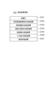
- the inspection result information 533 is composed of the following entries: container ID 5331, inspection result 5332 for foreign matter stuck to the bottle body, inspection result 5333 for scratches on the bottle body, inspection result 5334 for matter adhering to the back of the lid, inspection result 5335 for scratches on the bottom, other inspection results 5336, and final inspection result 5337.
- the entry for container ID 5331 is set with an ID that uniquely identifies the vial 110 being inspected.
- the entries for inspection result 5332 for foreign matter stuck to the bottle body, inspection result 5333 for scratches on the bottle body, inspection result 5334 for matter adhering to the back of the lid, and inspection result 5335 for scratches on the bottom are set with an inspection result of either OK (inspection passed) or NG (inspection failed).
- an inspection result of either OK (inspection passed) or NG (inspection failed) is set for each inspection item inspected.
- NG inspection failure
- the calculation processing unit 540 has a processor such as a CPU (Central Processing Unit) and its peripheral circuits, and is configured to read and execute a program 531 from the storage unit 530, thereby implementing various processing units through cooperation between the above hardware and the program 531.
- the main processing units implemented by the calculation processing unit 540 include a gripping/rotation control unit 541, an acquisition unit 542, a detection unit 543, and a display control unit 544.
- the gripping/rotation control unit 541 is configured to control the gripping/rotating device 200.
- the gripping/rotation control unit 541 controls the lowering, closing, rotating, opening, raising, and other operations of the chuck finger 211 by transmitting and receiving signals to and from the chuck mechanism 206 of the gripping/rotating device 200 through the communication I/F unit 510.
- the gripping/rotation control unit 541 also controls the rotation of the vial 110 gripped by the gripping/rotating device 200 about the rotation axis B by transmitting and receiving signals to and from the motor 207 through the communication I/F unit 510.
- the gripping/rotation control unit 541 also monitors the rotation angles of the vial 110 gripped by the gripping/rotating control unit 541 about the rotation axes A and B by transmitting and receiving signals to and from the rotation angle detectors 209 and 210 through the communication I/F unit 510.
- the acquisition unit 542 is configured to control the lighting device 300 and the camera device 400.
- the acquisition unit 542 controls the lighting device 300 to be turned on and off by transmitting and receiving signals to and from the lighting device 300 through the communication I/F unit 510.
- the acquisition unit 542 also controls the photographing of the vial 110 held by the gripping and rotating device 200 by transmitting and receiving signals to and from the camera device 400 through the communication I/F unit 510, and acquires time-series images obtained by photographing.
- the acquisition unit 542 also creates image information 532 based on the images acquired from the camera device 400 and information on the rotation angles of the vial 110 about the rotation axes A and B monitored by the rotation angle detectors 209 and 210, and stores the image information in the storage unit 530.
- the detection unit 543 is configured to inspect the presence or absence of defects in the vial 110 based on the image information 532 acquired by the acquisition unit 542.
- the detection unit 543 is also configured to create inspection result information 533 based on the inspection results and store it in the storage unit 530.
- the display control unit 544 is configured to output the test result information 533 created by the detection unit 543 to the display device 600.
- FIG. 5 is a flow chart showing an example of the processing of the inspection system 100.
- the inspection system 100 performs the processing shown in FIG. 5 for each vial 110 to be inspected. Dust and other particles that may adhere to the outside of the vial 110 to be inspected are blown away with air immediately before inspection.
- the gripping and rotating device 200 is in an initial state.
- the chuck finger 211 of the gripping and rotating device 200 is open and in an elevated position and stops rotating.
- the rotation angle around the rotation axis A detected by the rotation angle detector 209 is set to 0°.
- the motor 207 of the gripping and rotating device 200 stops the rotation of the flat member 201 around the rotation axis B at an angle where the rotation axis A coincides with the vertical.
- the rotation angle around the rotation axis B detected by the rotation angle detector 210 is set to 0°.
- the gripping and rotating device 200 of the inspection system 100 carries in the vial 110 to be inspected (step S1).
- the gripping and rotating control unit 541 places the vial 110 in an upright position at a predetermined position on the transparent plate 205 of the gripping and rotating device 200, for example, by using a robot arm or manual labor not shown.
- the gripping/rotation control unit 541 controls the chuck mechanism 206 to lower the chuck finger 211 and chuck the head of the vial 110.
- the vial 110 to be inspected is gripped by the gripping/rotation device 200 in an upright position.
- the central axis of the vial 110 approximately coincides with the rotation axis A and becomes vertical.
- the inspection system 100 rotates and photographs the vial 110 (step S2).
- the gripping/rotation control unit 541 controls the chuck mechanism 206 and the motor 207 to rotate the vial 110 around the rotation axis A and the rotation axis B according to a preset rotation angle timeline.
- the gripping/rotation control unit 541 starts rotating the vial 110 around the rotation axis A, it issues a rotation start command to the chuck mechanism 206 specifying the rotation direction, and when it ends the rotation, it issues a rotation end command to the chuck mechanism 206.
- the gripping/rotation control unit 541 rotates the vial 110 around the rotation axis B, it issues a rotation start command to the motor 207 specifying the rotation direction, and when it ends the rotation, it issues a rotation end command to the motor 207.
- the grip/rotation control unit 541 also monitors the rotation angles around the rotation axis A and the rotation axis B detected by the rotation angle detector 209 and the rotation angle detector 210.
- step S2 when the camera device 400-1 starts photographing the vial 110, the acquisition unit 542 issues a turn-on command to the lighting device 300-1 and issues a start photographing command to the camera device 400-1, and when the photographing ends, it issues a turn-off command to the lighting device 300-1 and issues an end photographing command to the camera device 400-1. Also, when the camera device 400-2 starts photographing the vial 110, the acquisition unit 542 issues a turn-on command to the lighting device 300-2 and issues a start photographing command to the camera device 400-2, and when the photographing ends, it issues a turn-off command to the lighting device 300-2 and issues an end photographing command to the camera device 400-2. However, the lighting devices 300-1 and 300-2 may be always turned on.
- the acquisition unit 542 may issue a command to control the zoom and/or focus to the camera device 400, so that the zoom amount and/or focus value of the camera device 400 can be changed during photographing.
- the gripping/rotation control unit 541 and the acquisition unit 542 are configured to operate in synchronization. For example, when the vial 110 is rotated around the rotation axis A and image capture is started by the camera device 400-1 at the same time, the gripping/rotation control unit 541 issues a rotation start command to the chuck mechanism 206, and the acquisition unit 542 issues an image capture start command to the camera device 400-1 in synchronization with the rotation start command.
- step S2 while the camera device 400 is capturing images, the acquisition unit 542 receives time-series images sent from the camera device 400 together with information indicating the capture time, etc.
- the acquisition unit 542 also receives information on the monitored rotation angles around the rotation axis A and the rotation axis B from the rotation angle detectors 209, 210 via the grip/rotation control unit 541.
- the acquisition unit 542 then associates the time-series images received from the camera device 400 with the capture time and the rotation angles around the rotation axis A and the rotation axis B, and stores them in the storage unit 530 as image information 532.
- the acquisition unit 542 uses information on the monitored rotation angles around the rotation axis A and the rotation axis B.
- the rotation angle timeline is set in advance and is known, processing may be performed assuming that rotation always starts and ends at a fixed time.
- the acquisition unit 542 automatically determines the programmed rotation angles of rotation axis A and rotation axis B from the time information of the operation start command from the information processing device 500, associates it with a time-series image, and stores it in the storage unit 530 as image information 532.
- the detection unit 543 of the inspection system 100 inspects the presence or absence of defects in the vial 110 based on the acquired image information 532, creates inspection result information 533 based on the inspection result, and stores it in the storage unit 530 (step S3).
- the display control unit 544 of the inspection system 100 displays the inspection result information 533 on the display device 600 and/or transmits it to an external device (not shown) through the communication I/F unit 510 (step S4).
- the inspection system 100 carries out the vial 110 that has been inspected (step S5).
- the gripping/rotating control unit 541 controls the chuck mechanism 206 to release the chuck finger 211 and then raise it, and moves the vial 110 on the transparent plate 205 of the gripping/rotating device 200 to a storage location according to the inspection result using a robot arm or human hands (not shown) in the above.
- defect detection by image analysis step S3 was performed.
- the rotation and photographing of the vial 110 (step S2) and defect detection through image analysis (step S3) may be performed simultaneously (sequential processing).
- FIG. 6 is a diagram showing an example of a rotation angle timeline.
- the vial 110 is rotated as follows: Interval 1 (time t0-t1): Stationary in an upright position Interval 2 (time t1-t2): Rotates 360° around rotation axis A.
- Section 5 (time t4-t5): Rotated -5° around rotation axis B.
- Section 6 (time t5-t6): Section 5, i.e., rotation -180° around rotation axis A in a sideways position.
- Section 7 (time t6-t7): Rotate 180° around rotation axis A in a sideways position.
- Section 8 (time t7-t9): After rotating -170° around rotation axis B, immediately rotate 80°.
- Section 9 (time t9-t10): Stationary in the same position as section 1.
- Section 10 (time t10-t11): Rotate -360° around rotation axis A.
- Section 11 (time t11-t12): Stationary in the same position as in section 1.
- the rotation angle of rotation axis A in section 2 does not need to be 360° depending on the vial diameter and the thickness of the glass on the side of the vial, and may be a value smaller than 360°, for example, 355°.
- the rotation angle in section 10 is an angle that returns the angle rotated in section 2.
- the rotation angle of rotation axis B in section 8 may be changed depending on the vial diameter and the amount of liquid content filled.
- the acquisition unit 542 When the vial 110 is rotated along the rotation angle timeline shown in FIG. 6, the acquisition unit 542, for example, at time t0, sends a turn-on command to the lighting devices 300-1 and 300-2 and a start image capture command to the camera devices 400-1 and 400-2, and at time t12, sends a turn-off command to the lighting devices 300-1 and 300-2 and a stop image capture command to the camera devices 400-1 and 400-2.
- This causes the camera devices 400-1 and 400-2 to capture images of the vial 110 over the entire section of the rotation angle timeline in FIG. 6.
- image capture by the camera devices 400-1 and 400-2 may be limited to a certain section.
- FIG. 7 is a schematic diagram showing how the upright vial 110 is photographed by camera device 400-1 and camera device 400-2 in sections 2 and 10.
- the vial 110 rotates 360° around rotation axis A in an upright position
- the vial 110 rotates -360° around rotation axis A in an upright position.
- Camera device 400-1 photographs the body of the rotating vial 110 from a direction perpendicular to rotation axis A
- camera device 400-2 photographs the rotating vial 110 from the bottom side of the vial 110 in a direction parallel to rotation axis A.
- FIG. 8 is a schematic diagram showing how the vial 110 in a sideways position is photographed by camera device 400-1 and camera device 400-2 in sections 6 and 7.
- the vial 110 in a sideways position rotates -180° and 180° around rotation axis A.
- Camera device 400-1 photographs the body of the rotating vial 110 from a direction perpendicular to rotation axis A.
- camera device 400-2 photographs the rotating vial 110 from a direction parallel to rotation axis A and from the bottom side of the vial.
- the inventor of the present application discovered the following phenomenon in the process of searching for a method of inspecting foreign matter stuck to the inner wall of the vial. That is, when the vial is turned on its side and rotated around the central axis so that the foreign matter stuck to the inner wall of the vial passes through the boundary between inside and outside the liquid, the position of the foreign matter stuck to the inner wall of the vial changes slightly.
- the foreign matter stuck to the inner wall of the vial is mainly fiber pieces, and when the vial is rotated as described above, the shape of the stuck fiber pieces changes.
- the reason for this phenomenon is considered to be that the foreign matter stuck to the inner wall of the vial is pulled by the surface tension of the liquid surface when passing through the boundary between inside and outside the liquid due to the rotation.
- the amount of liquid filled in the vial is approximately half the capacity of the vial, so that the liquid level height R of the vial 110 in the turned-over position is approximately near the center of the bottle body, and the lower half of the inner wall of the bottle body is in the liquid and the upper half is outside the liquid, as shown in FIG. 8.
- the vial 110 when the vial 110 is rotated about the rotation axis A by ⁇ 180° or more, the foreign matter attached to the inner wall of the bottle body passes through the boundary between the inside and outside of the liquid as it rotates, and is affected by the surface tension of the liquid surface.
- the vial 110 when the vial 110 is rotated about the rotation axis A in a sideways position, the foreign matter attached to the back of the lid or the bottom of the vial 110 also passes through the boundary between the inside and outside of the liquid as it rotates. Therefore, it is expected that not only the foreign matter attached to the inner wall of the bottle body, but also the position and shape of the foreign matter attached to the back of the lid or the bottom will change.
- the foreign matter attached to the inner wall may be completely peeled off, or the foreign matter floating in the liquid may newly stick to the inner wall.
- the foreign matter before peeling off and the newly attached foreign matter will be detected as the difference between the images before and after rotation, as well as the foreign matter that remains attached before and after rotation.
- the camera device 400-1 photographs the same area of the vial body of the vial 110 before and after sections 6 and 7 in which the vial 110 is rotated around rotation axis A in a sideways position, and the images obtained before and after the rotation are compared to distinguish and detect foreign objects stuck to the bottle body, scratches on the bottle body, etc.
- FIG. 9 is a flow chart showing an example of a process in which the detection unit 543 detects foreign matter stuck to the bottle body and scratches on the bottle body.
- the detection unit 543 acquires all entries including the camera ID 5322 of the camera device 400-1 and the shooting time 5323 included in section 2 as first entries from the image information 532 shown in FIG. 3 (step S11).
- the frame image included in this first entry corresponds to the image before rotation described above.
- the detection unit 543 also acquires all entries including the camera ID 5322 of the camera device 400-1 and the shooting time 5323 included in section 10 as second entries from the image information 532 shown in FIG. 3 (step S12).
- the frame image included in this second entry corresponds to the image after rotation described above.
- the detection unit 543 generates all pairs of the first entry and the second entry in which the rotation angle 5324 of the rotation axis A is the same (step S13).
- the detection unit 543 focuses on one of the pairs (step S14), compares the frame image 5326 of the first entry of the focused pair with the frame image 5326 of the second entry (step S15), and determines whether the images of the bottle body are the same or different in both frame images (step S16).
- the detection unit 543 may, for example, take the difference between the image of the bottle body in the frame image 5326 of the first entry and the image of the bottle body in the frame image 5326 of the second entry, and determine that there is a difference and that there is no difference and that there is the same.
- the method of determining whether the images of the bottle body in both frame images are the same or different is not limited to the method based on the difference, and any other method may be used.
- the detection unit 543 determines that this is due to a foreign object stuck to the bottle body, and increments the foreign object stuck to the bottle body counter (initial value is 0) (step S17).
- the detection unit 543 determines that this is due to a foreign object stuck to the bottle body, and increments the foreign object stuck to the bottle body counter (initial value is 0) (step S17).
- the dark area is a foreign object such as a piece of fiber, or a liquid droplet other than a foreign object, based on information on the appearance, such as the shape and color, of the dark area in the frame image that caused the difference.
- the detection unit 543 determines whether or not there is a dark area of a size equal to or larger than the threshold size in the image of the bottle body of the frame image of the first entry or the second entry of the pair under consideration (step S18). Note that since the image of the bottle body shows the bottle wall and its vicinity as dark areas, it may be possible to determine whether or not there is a dark area of a size equal to or larger than the threshold size in other locations (such as the center of the bottle body).
- the detection unit 543 determines that the dark area is a scratch on the bottle body of an unacceptable size, and increments the bottle body scratch counter (initial value is 0) (step S19).
- the threshold size is on the order of millimeters. This is because scratches smaller than the order of millimeters are not considered a problem.
- the detection unit 543 shifts its attention to the next pair (steps S20, S21), returns to step S15, and repeats the same process as described above. Then, when the detection unit 543 has finished paying attention to all the necessary pairs (YES in step S21), it updates the inspection result information 533 (step S22).
- the "necessary pair" in step S21 may be, for example, a pair of the minimum number of sheets in which the entire area is visible in front.
- the detection unit 543 updates the inspection result 5332 for foreign matter stuck to the bottle body and the inspection result 5333 for damage to the bottle body in the inspection result information 533 in which the container ID 5331 of the vial 110 to be inspected is set.
- the detection unit 543 sets NG (inspection failed) and if it is less than 1, sets OK (inspection passed). Furthermore, when updating the bottle body damage inspection results 5333, the detection unit 543 sets NG (inspection failed) if the value of the bottle body damage counter is 1 or more, and sets OK (inspection passed) if it is less than 1.
- the value of the bottle body stuck foreign matter counter which is a measure of the number of foreign matter stuck to the bottle body, may be stored in the bottle body stuck foreign matter inspection results 5332.
- the value of the bottle body damage counter which is a measure of the number of scratches on the bottle body, may be stored in the bottle body damage inspection results 5333.
- step S22 immediately when the bottle body adhered foreign matter counter and/or the bottle body scratch counter reach a value of 1 or more, and then terminate the process of FIG. 9.
- the amount of liquid filled in the vial 110 is approximately half the capacity of the vial 110. Therefore, as shown in FIG. 8, the liquid level of the vial 110 in the lying position is approximately at the center of the bottle body, and at least the upper half of the bottle body is in a state where no liquid exists.
- the camera device 400-2 photographs the vial 110 in such a state from the direction parallel to the rotation axis A and from the bottle bottom side. Therefore, the camera device 400-2 can photograph a part of the back of the lid of the vial 110 without passing through the liquid (and therefore without being affected by air bubbles present in the liquid).
- the image photographed by the camera device 400-2 shows a part of the back of the lid of the vial 110 photographed without passing through the liquid.
- the vial 110 is stationary, the range of the back of the lid that can be photographed without passing through the liquid is limited to a part.
- the vial 110 is rotated -180° around the rotation axis A and then rotated 180°, and the camera device 400-2 captures images during the rotation. Therefore, by collecting multiple frame images captured by the camera device 400-2 in sections 6 and/or 7, the entire back of the lid can be observed without passing through liquid.
- the detection unit 543 detects the matter adhering to the back of the lid based on the images of the back of the lid of the vial 110 captured without passing through liquid as described above.
- the detection unit 543 acquires all entries including the camera ID 5322 of the camera device 400-2 and the shooting time 5323 included in section 6 or/and section 7 from the image information 532 shown in FIG. 3 (step S31).
- the detection unit 543 focuses on one entry (step S32).
- the detection unit 543 compares the frame image 5326 of the entry being focused on with a reference image (not shown) stored in the storage unit 530 (step S33) and determines whether the two images are the same or different (step S34).
- the shape and color of the back of the lid of the vial 110 are determined for each type of vial.
- the reference image is a previously captured image of the back of the lid of a vial of the same type as the vial 110 to be inspected, without a lid back attachment, by the camera device 400-2 and stored in the storage unit 530.
- the detection unit 543 may, for example, take the difference between the frame image 5326 and the reference image, and determine that they are different if there is a difference, and that they are the same if there is no difference.
- the range of the frame image 5326 from which the difference with the reference image is taken may be the entire frame image 5326, may be the entire range of the lid back in the frame image 5326, or may be limited to the range of the lid back photographed without liquid.
- the method of determining whether the frame image 5326 and the reference image are the same or different is not limited to the method based on the difference, and any other method may be used.
- step S35 if there is a difference between frame image 5326 and the reference image, detection unit 543 determines that this is due to a lid back attachment, and increments the lid back attachment counter (initial value is 0) (step S35).
- the lid back attachment counter increments the lid back attachment counter (initial value is 0) (step S35).
- the detection unit 543 skips step S35.
- the detection unit 543 shifts its attention to the next entry (steps S36, S37), returns to step S33, and repeats the same process as described above.
- the detection unit 543 has finished paying attention to all entries (YES in step S37)
- it updates the inspection result information 533 (step S38).
- the detection unit 543 updates the inspection result 5334 of the lid back attachment in the inspection result information 533 in which the container ID 5331 of the vial 110 to be inspected is set.
- the detection unit 543 sets NG (inspection failed) and if it is less than 1, sets OK (inspection passed). Note that the value of the lid back attachment counter, which is an indication of the number of lid back attachments, may be saved in the lid back attachment inspection result 5334.
- step S38 immediately when the lid back deposit counter reaches a value of 1 or more, and then terminate the process of Figure 10.
- FIG. 11 is a flowchart showing an example of a process in which the detection unit 543 detects bottom scratches and bottom foreign objects.
- the detection unit 543 acquires all entries including the camera ID 5322 of the camera device 400-2 and the shooting time 5323 included in the section 2 as first entries from the image information 532 shown in FIG. 3 (step S41).
- the frame image included in this first entry corresponds to an image obtained by photographing the vial 110 from the bottle bottom side by the camera device 400-2 before rotating the vial 110 around the rotation axis A in a sideways position.
- the detection unit 543 acquires all entries including the camera ID 5322 of the camera device 400-2 and the shooting time 5323 included in the section 10 as second entries from the image information 532 shown in FIG. 3 (step S42).
- the frame image included in this second entry corresponds to an image obtained by rotating vial 110 on its side about rotation axis A and then photographing vial 110 from the bottom side with camera device 400-2.
- the detection unit 543 generates a pair of a first entry and a second entry in which the rotation angle 5324 of the rotation axis A is the same (step S43).
- the detection unit 543 focuses on one of the pairs (step S44), compares the frame image 5326 of the first entry of the focused pair with the frame image 5326 of the second entry (step S45), and determines whether the two frame images are the same or different (step S46).
- the detection unit 543 may, for example, take the difference between the image of the bottle bottom in the frame image 5326 of the first entry and the image of the bottle bottom in the frame image 5326 of the second entry, and determine that there is a difference and that there is no difference and that there is the same.
- the method of determining whether the images of the bottle bottom in both frame images are the same or different is not limited to the method based on the difference, and any other method may be used.
- the detection unit 543 determines that this is due to a foreign object that has settled or stuck to the bottom surface of the vial 110, and increments the bottom foreign object counter (initial value is 0) (step S47).
- the bottom foreign object counter increments the bottom foreign object counter (initial value is 0)
- the dark part is a foreign object such as a piece of metal or fiber, or a large bubble other than a foreign object, based on appearance information such as the shape and color of the dark part of the frame image that caused the difference.
- the detection unit 543 determines whether or not a dark area of a size equal to or larger than the threshold size is present in the frame image of the first or second entry of the pair under consideration (step S48). Note that since the image of the bottom of the bottle shows the bottle wall and its vicinity as dark areas, it may be possible to determine whether or not a dark area of a size equal to or larger than the threshold size is present in other locations (such as the center of the bottom of the bottle). If a dark area of a size equal to or larger than the threshold size is present, the detection unit 543 determines that the dark area is a bottom scratch of an unacceptable size, and increments the bottom scratch counter (initial value is 0) (step S49).
- the threshold size is on the order of millimeters. This is because scratches smaller than the order of millimeters are not considered a problem.
- the detection unit 543 shifts its attention to the next pair (steps S50, S51), and returns to step S45 to repeat the same process as described above. Then, when the detection unit 543 has finished paying attention to all pairs (YES in step S51), it updates the inspection result information 533 (step S52). In this step S52, the detection unit 543 updates the bottom scratch inspection result 5335 and other inspection results 5336 of the inspection result information 533 in which the container ID 5331 of the vial 110 to be inspected is set. In updating the bottom scratch inspection result 5335, if the value of the bottom scratch counter is 1 or more, the detection unit 543 sets NG (inspection failed) and if it is less than 1, sets OK (inspection passed).
- the detection unit 543 adds an inspection item for bottom foreign matter to the other inspection results 5336 and sets NG (inspection failed), and if the value is less than 1, sets OK (inspection passed).
- the values of the bottom scratch counter and bottom foreign matter count which are indicators of the number of bottom scratches and bottom foreign matter, may be saved in the bottom scratch inspection result 5335 and the bottom foreign matter inspection item of the other inspection results 5336.
- step S52 the process is repeated for all pairs, but it is also possible to execute step S52 immediately when the bottom scratch counter and/or bottom foreign object counter reach a value of 1 or more, and then terminate the process of FIG. 11.
- the inspection system 100 performs a process of rotating the vial 110 around its central axis (rotation axis A) in a horizontal position (section 6 or section 7 in FIG. 6).
- This induces a phenomenon in which the position and shape of the foreign matter adhering to the inner wall of the vial 110 changes when the foreign matter passes through the boundary between inside and outside the liquid and is pulled by the surface tension of the liquid surface. That is, the position of the foreign matter adhering to the inner wall of the vial 110 can be changed.
- the inspection system 100 then obtains an image before rotation (image of section 2 in FIG. 6) and an image after rotation (image of section 10 in FIG.
- the foreign matter adhering to the inner wall of the vial 110 can be detected separately from scratches whose position and shape do not change even when the above process is performed.
- the inspection system 100 rotates the vial 110 around its central axis (rotation axis A) while the vial 110 is in a sideways position, and acquires an image (an image of section 6 or section 7 in FIG. 6) of the back side of the lid of the rotating vial 110 through the area outside the liquid from the bottom side of the vial 110 using the camera device 400-2 having an optical axis parallel to the central axis (rotation axis A). Therefore, the camera device 400-2 can capture a part of the back side of the lid of the vial 110 without passing through the liquid. That is, the image captured by the camera device 400-2 captures a part of the back side of the lid of the vial 110 without passing through the liquid.
- the camera device 400-2 having a telecentric lens is used, so that the liquid surface is not captured as much as possible (so that the thickness of the liquid surface contour in the image is thin), and the back side of the lid, which is the farthest from the camera, can be captured in a large size.
- This embodiment can be modified in various ways, such as:
- bottles and containers other than vials can also be tested as long as they are transparent or translucent containers filled with liquids such as drinking water.
- the inspection system 100 rotates the vial 110 by -180° (half rotation) and then 180° (half rotation) around the rotation axis A in sections 6 and 7 of the rotation angle timeline in Figure 6, but this is merely one example. If the amount of liquid is approximately half the vial capacity, the vial 110 only needs to be rotated at least 180° (half rotation) in the positive or negative direction around the rotation axis A. This is because all areas of the inner wall of the bottle body will pass the boundary between in and out of the liquid at least once. Alternatively, the inspection system 100 may detect the amount of liquid filled and determine the amount of rotation in sections 6 and 7 depending on the detected amount of liquid.
- the inspection system 100 may detect the height of the liquid level of the vial 110 in a sideways position by image analysis or the like, calculate the minimum rotation angle around the rotation axis A required for all areas of the inner wall of the vial 110 to pass the boundary between inside and outside the liquid at least once from the detected liquid level, and rotate the vial 110 around the rotation axis A by at least this calculated minimum rotation angle.
- the vial 110 is filled with liquid, by rotating the vial 110 at least 360° (one rotation) in the positive or negative direction around the rotation axis A, all areas of the inner wall of the vial 110 will necessarily pass the boundary between inside and outside the liquid at least once.
- the vial 110 may be rotated at least 360° (one rotation) in the positive or negative direction around the rotation axis A.
- the inspection system 100 rotates the vial 110 once around the rotation axis A, but may rotate the vial 110 one or more times (for example, two or more times).
- the inspection system 100 rotates the vial 110 by ⁇ 170° around the rotation axis B in section 8, and then immediately rotates it by 80°.
- the inspection system 100 may only rotate the vial 110 by ⁇ 90° around the rotation axis B. That is, in section 8, the inspection system 100 may only return the vial 110, which is in a sideways position, to an upright position again.
- the inspection system 100 may also use a section in which the vial 110 is laid on its side and rotated around its central axis (rotation axis A) as a section in which the camera device 400 captures images of the same specified area, such as the bottle body of the vial 110, before and after the process of laying the vial 110 on its side and rotating it around its central axis (rotation axis A) (section 6 or section 7 in FIG. 6). This will be described in detail below with reference to FIG. 12.
- FIG. 12 is a diagram showing another example of a rotation angle timeline.
- the vial 110 is rotated as follows.
- Interval 1 time t0-t1: Stationary in an upright position
- Interval 2 time t1-t2: Rotated 90° around rotation axis B.
- Section 3 time t2-t3): Rotate 360° around rotation axis A in a sideways position.
- Section 4 (time t3-t4): Rotate -360° around rotation axis A in a sideways position.
- Section 5 (time t4-t5): Rotate 360° around rotation axis A in a sideways position.
- Section 6 time t5-t6): Rotate -90° around rotation axis B.
- Section 7 time t6-t7): Stationary in the same position as section 1.
- Section 4 in FIG. 12 is the process of placing the vial 110 in a sideways position and rotating it at least once around its central axis (rotation axis A), and sections 3 and 5 are the processes of photographing the same specified area of the vial 110, such as the bottle body, with the camera device 400 before and after the process.
- Fig. 13 is a block diagram showing the configuration of an inspection system 1 in this embodiment.
- the inspection system 1 is an apparatus for inspecting a container filled with liquid, and includes a rotation unit 2 and an acquisition unit 3.
- the rotating unit 2 is configured to perform a first rotation process in which the container is placed in a sideways position and rotated around the central axis of the container.
- the rotating unit 2 can be configured in the same manner as the gripping and rotating device 200 in FIG. 1, for example, but is not limited to this.
- the acquisition unit 3 is configured to acquire images before and after rotation obtained by photographing the same specified area of the container with a camera before and after the first rotation process is performed by the rotation unit 2.
- the acquisition unit 3 can be configured, for example, in the same way as the acquisition unit 542 in FIG. 2, but is not limited thereto.
- the inspection system 1 configured in this manner operates as follows. That is, the rotation unit 2 performs a first rotation process in which the container is placed in a sideways position and rotated around the central axis of the container.
- the acquisition unit 3 acquires pre-rotation and post-rotation images obtained by photographing the same specified area of the container with a camera before and after the first rotation process is performed by the rotation unit 2.
- the first rotation process induces a phenomenon in which the position of a foreign object stuck to the inner wall of the container changes as the foreign object is pulled by the surface tension of the liquid surface as it passes through the boundary between inside and outside the liquid.
- the position of the foreign object stuck to the inner wall of the container can be changed.
- the inspection device 1 then obtains images before and after rotation obtained by photographing the same specified area of the container with a camera before and after the first rotation process is performed.
- a detection unit that compares the images before and after rotation to detect foreign objects attached to the inner wall of the container, foreign objects stuck to the inner wall of the container can be detected separately from scratches whose position or shape does not change even when the first rotation process is performed.
- the information processing device can use a GPU (Graphic Processing Unit), a DSP (Digital Signal Processor), an MPU (Micro Processing Unit), an FPU (Floating number Processing Unit), a PPU (Physics Processing Unit), a TPU (Tensor Processing Unit), a quantum processor, a microcontroller, or a combination of these.
- a GPU Graphic Processing Unit
- DSP Digital Signal Processor
- MPU Micro Processing Unit
- FPU Floating number Processing Unit
- PPU Physicals Processing Unit
- TPU Tinsor Processing Unit
- quantum processor a microcontroller, or a combination of these.
- the present invention can be used in fields such as inspecting containers filled with liquids, such as vials.
- a system for inspecting a container filled with liquid comprising: a rotating unit that performs a first rotation step of rotating the container around a central axis of the container in a sideways position; an acquisition unit that acquires images before and after rotation by photographing the same predetermined area of the container with a camera before and after the first rotation step is performed by the rotation unit;
- An inspection system comprising: [Appendix 2] the rotating unit performs a second rotation step of rotating the container around the central axis with the container in an upright position before the first rotation step, and performs a third rotation step of rotating the container around the central axis with the container in an upright position after the first rotation step, the acquisition unit acquires the pre-rotation image from images captured by the camera during the second rotation process, and acquires the post-rotation image from images captured by the camera during the third rotation process.
- the inspection system of claim 1 [Appendix 3] The rotating unit performs a second rotation step of turning the container sideways and rotating the container around a central axis of the container before the first rotation step, and performs a third rotation step of turning the container sideways and rotating the container around the central axis of the container after the first rotation step, the acquisition unit acquires the pre-rotation image from images captured by the camera during the second rotation process, and acquires the post-rotation image from images captured by the camera during the third rotation process. 3. The inspection system of claim 1 or 2. [Appendix 4] A detection unit is further provided which detects foreign matter attached to an inner wall of the container by comparing the image before the rotation with the image after the rotation. 4. An inspection system according to any one of claims 1 to 3.
- the detection unit further compares the image before rotation with the image after rotation to detect scratches on the container. 5.
- the camera has an optical axis perpendicular to the central axis; 6.
- the predetermined area includes a body portion of the container. 7.
- the camera has an optical axis parallel to the central axis. 6.
- the predetermined area includes a bottom area of the container. 9.
- [Appendix 10] The predetermined area includes an area behind the lid of the container. 9.
- a method for inspecting a container filled with liquid comprising: A first rotation step is performed in which the container is placed in a sideways position and rotated at least once around a central axis of the container; acquiring images before and after the first rotation step by photographing the same predetermined area of the container with a camera; and Inspection method.
- a second rotation step of rotating the container around the central axis in an upright position before the first rotation step a third rotation step of rotating the container around the central axis in an upright position after the first rotation step;
- the pre-rotation image is acquired from the images captured by the camera during the second rotation process
- the post-rotation image is acquired from the images captured by the camera during the third rotation process.
- the detection further includes comparing the image before rotation with the image after rotation to detect scratches on the container. 21.
- [Appendix 22] the camera has an optical axis perpendicular to the central axis; 22.
- [Appendix 23] The predetermined area includes a body portion of the container. 23.
- [Appendix 24] The camera has an optical axis parallel to the central axis. 22.
- [Appendix 25] The predetermined area includes a bottom area of the container. 25.
- the predetermined area includes an area behind the lid of the container. 21.
- the camera has a wide-angle lens. 23.
- the camera has a telecentric lens. 23.
- [Appendix 29] In the first rotating step, the container is rotated so that substantially the entire area of the inner wall of the container passes through a boundary between inside and outside the liquid at least once. 23.
- the first rotating step rotates the container at least half a rotation about a central axis of the container.
- Inspection system 2 Rotation unit 3 Acquisition unit 100 Inspection system 110 Vial 200 Grip/rotate device 201 Flat plate member 202 Upper arm 203 Lower arm 204 Lower gripping unit 205 Transparent plate 206 Chuck mechanism 207 Motor 208 Rotating shaft 209, 210 Rotation angle detector 211 Chuck finger 300-1, 300-2 Illumination device 400-1, 400-2 Camera device 500 Information processing device 510 Communication I/F unit 520 Operation input unit 530 Memory unit 531 Program 532 Image information 533 Inspection result information 540 Arithmetic processing unit 541 Grip/rotate control unit 542 Acquisition unit 543 Detection unit 544 Display control unit 600 Display device
Landscapes
- Physics & Mathematics (AREA)
- Health & Medical Sciences (AREA)
- Life Sciences & Earth Sciences (AREA)
- Chemical & Material Sciences (AREA)
- Analytical Chemistry (AREA)
- Biochemistry (AREA)
- General Health & Medical Sciences (AREA)
- General Physics & Mathematics (AREA)
- Immunology (AREA)
- Pathology (AREA)
- Engineering & Computer Science (AREA)
- Computer Vision & Pattern Recognition (AREA)
- Signal Processing (AREA)
- Investigating Materials By The Use Of Optical Means Adapted For Particular Applications (AREA)
Priority Applications (3)
| Application Number | Priority Date | Filing Date | Title |
|---|---|---|---|
| PCT/JP2022/038266 WO2024079857A1 (ja) | 2022-10-13 | 2022-10-13 | 検査システム |
| US19/112,639 US20260086040A1 (en) | 2022-10-13 | 2022-10-13 | Inspection system |
| JP2024551007A JPWO2024079857A1 (https=) | 2022-10-13 | 2022-10-13 |
Applications Claiming Priority (1)
| Application Number | Priority Date | Filing Date | Title |
|---|---|---|---|
| PCT/JP2022/038266 WO2024079857A1 (ja) | 2022-10-13 | 2022-10-13 | 検査システム |
Publications (1)
| Publication Number | Publication Date |
|---|---|
| WO2024079857A1 true WO2024079857A1 (ja) | 2024-04-18 |
Family
ID=90669025
Family Applications (1)
| Application Number | Title | Priority Date | Filing Date |
|---|---|---|---|
| PCT/JP2022/038266 Ceased WO2024079857A1 (ja) | 2022-10-13 | 2022-10-13 | 検査システム |
Country Status (3)
| Country | Link |
|---|---|
| US (1) | US20260086040A1 (https=) |
| JP (1) | JPWO2024079857A1 (https=) |
| WO (1) | WO2024079857A1 (https=) |
Citations (4)
| Publication number | Priority date | Publication date | Assignee | Title |
|---|---|---|---|---|
| JP2001215199A (ja) * | 2000-02-01 | 2001-08-10 | Sukiyan Technol:Kk | 容器の検査方法。 |
| JP2018205199A (ja) * | 2017-06-07 | 2018-12-27 | 株式会社 日立産業制御ソリューションズ | 異物検査装置及び方法 |
| US20200110042A1 (en) * | 2017-03-23 | 2020-04-09 | Antares Vision S.P.A. | An inspection machine |
| JP3236441U (ja) * | 2021-12-20 | 2022-02-18 | 一郎 渡邊 | カメラユニット及びそれを用いた外観検査装置 |
-
2022
- 2022-10-13 JP JP2024551007A patent/JPWO2024079857A1/ja active Pending
- 2022-10-13 WO PCT/JP2022/038266 patent/WO2024079857A1/ja not_active Ceased
- 2022-10-13 US US19/112,639 patent/US20260086040A1/en active Pending
Patent Citations (4)
| Publication number | Priority date | Publication date | Assignee | Title |
|---|---|---|---|---|
| JP2001215199A (ja) * | 2000-02-01 | 2001-08-10 | Sukiyan Technol:Kk | 容器の検査方法。 |
| US20200110042A1 (en) * | 2017-03-23 | 2020-04-09 | Antares Vision S.P.A. | An inspection machine |
| JP2018205199A (ja) * | 2017-06-07 | 2018-12-27 | 株式会社 日立産業制御ソリューションズ | 異物検査装置及び方法 |
| JP3236441U (ja) * | 2021-12-20 | 2022-02-18 | 一郎 渡邊 | カメラユニット及びそれを用いた外観検査装置 |
Also Published As
| Publication number | Publication date |
|---|---|
| JPWO2024079857A1 (https=) | 2024-04-18 |
| US20260086040A1 (en) | 2026-03-26 |
Similar Documents
| Publication | Publication Date | Title |
|---|---|---|
| TWI582408B (zh) | 用於非破壞性檢測-流體中未溶解粒子之方法及裝置 | |
| JPH10505680A (ja) | 環状レンズを用いた容器フランジ検査システム | |
| JP5154479B2 (ja) | 液体中の異物検査方法 | |
| JP7359297B2 (ja) | 検査システム | |
| JP2010048602A (ja) | プリント基板検査装置及び検査方法 | |
| JP2010181231A (ja) | 不透明溶液中の異物検査装置および異物検査方法 | |
| WO2022244075A1 (ja) | 検査システム | |
| CN103119395B (zh) | 玻璃瓶检查装置 | |
| WO2016186018A1 (ja) | 容器検査装置及び検査方法 | |
| JP5352444B2 (ja) | 外観検査装置、表面検査装置、及び外観検査方法 | |
| JP2016090293A (ja) | 管材の内面検査装置及びそれを用いた検査方法 | |
| JP2001116703A (ja) | 容器内浮遊物判別方法及びその装置 | |
| JP2004257937A (ja) | 異物検査装置および検査方法 | |
| JPH08189903A (ja) | 気泡検査装置 | |
| CN112129782A (zh) | 显示面板异物分层检测方法和装置 | |
| WO2024079857A1 (ja) | 検査システム | |
| WO2024079858A1 (ja) | 検査システム | |
| KR20100093213A (ko) | 휘도값을 이용한 글래스 기판 상의 이물 감지 시스템 및 그방법 | |
| JP2009103494A (ja) | 表面検査装置 | |
| JPH0436644A (ja) | 円筒内壁面の欠陥の検査方法 | |
| JP3816226B2 (ja) | 光ファイバ母材の検査装置 | |
| WO2025027717A1 (ja) | 検査装置 | |
| JP2004226228A (ja) | 溶液中の異物検査方法およびその装置 | |
| JP2002267612A (ja) | 透明容器等の充填液体中の異物検査装置及びシステム | |
| WO2025154143A1 (ja) | 検査装置 |
Legal Events
| Date | Code | Title | Description |
|---|---|---|---|
| 121 | Ep: the epo has been informed by wipo that ep was designated in this application |
Ref document number: 22962075 Country of ref document: EP Kind code of ref document: A1 |
|
| WWE | Wipo information: entry into national phase |
Ref document number: 2024551007 Country of ref document: JP |
|
| NENP | Non-entry into the national phase |
Ref country code: DE |
|
| 122 | Ep: pct application non-entry in european phase |
Ref document number: 22962075 Country of ref document: EP Kind code of ref document: A1 |