WO2024079857A1 - Inspection system - Google Patents
Inspection system Download PDFInfo
- Publication number
- WO2024079857A1 WO2024079857A1 PCT/JP2022/038266 JP2022038266W WO2024079857A1 WO 2024079857 A1 WO2024079857 A1 WO 2024079857A1 JP 2022038266 W JP2022038266 W JP 2022038266W WO 2024079857 A1 WO2024079857 A1 WO 2024079857A1
- Authority
- WO
- WIPO (PCT)
- Prior art keywords
- rotation
- container
- rotating
- image
- camera
- Prior art date
Links
- 238000007689 inspection Methods 0.000 title claims description 204
- 239000007788 liquid Substances 0.000 claims abstract description 76
- 238000000034 method Methods 0.000 claims description 102
- 238000001514 detection method Methods 0.000 claims description 59
- 230000008569 process Effects 0.000 claims description 55
- 230000003287 optical effect Effects 0.000 claims description 11
- 238000003384 imaging method Methods 0.000 abstract description 3
- 238000012545 processing Methods 0.000 description 24
- 230000010365 information processing Effects 0.000 description 19
- 238000010586 diagram Methods 0.000 description 16
- 230000007246 mechanism Effects 0.000 description 16
- 238000004891 communication Methods 0.000 description 12
- 230000007547 defect Effects 0.000 description 7
- 239000000835 fiber Substances 0.000 description 7
- 230000008859 change Effects 0.000 description 6
- 239000012634 fragment Substances 0.000 description 6
- 238000005286 illumination Methods 0.000 description 4
- 229910052782 aluminium Inorganic materials 0.000 description 3
- XAGFODPZIPBFFR-UHFFFAOYSA-N aluminium Chemical compound [Al] XAGFODPZIPBFFR-UHFFFAOYSA-N 0.000 description 3
- 230000006870 function Effects 0.000 description 3
- 238000010191 image analysis Methods 0.000 description 3
- 238000012360 testing method Methods 0.000 description 3
- 239000003814 drug Substances 0.000 description 2
- 230000000694 effects Effects 0.000 description 2
- 239000011521 glass Substances 0.000 description 2
- 229910052751 metal Inorganic materials 0.000 description 2
- 239000002184 metal Substances 0.000 description 2
- 239000004033 plastic Substances 0.000 description 2
- 230000004044 response Effects 0.000 description 2
- 238000004826 seaming Methods 0.000 description 2
- 230000000295 complement effect Effects 0.000 description 1
- 239000003651 drinking water Substances 0.000 description 1
- 235000020188 drinking water Nutrition 0.000 description 1
- 239000000428 dust Substances 0.000 description 1
- -1 hair Substances 0.000 description 1
- 239000004973 liquid crystal related substance Substances 0.000 description 1
- 239000000463 material Substances 0.000 description 1
- 238000012986 modification Methods 0.000 description 1
- 230000004048 modification Effects 0.000 description 1
- 239000002245 particle Substances 0.000 description 1
- 230000002093 peripheral effect Effects 0.000 description 1
- 239000004071 soot Substances 0.000 description 1
Images


Abstract
Provided is a system which inspects a container filled with liquid, the system comprising a rotation unit which executes a first rotation step of rotating the container about a center axis of the container while the container is in a horizontally-laid posture and an acquisition unit which acquires an image before the rotation and an image after the rotation obtained by a camera imaging the same predetermined region of the container before and after the execution of the first rotation step by the rotation unit, respectively.
Description
本発明は、検査システム、検査方法、および、記録媒体に関する。
The present invention relates to an inspection system, an inspection method, and a recording medium.
液体が充填された容器を検査する装置が各種提案ないし実用化されている。
Various devices have been proposed or put into practical use to inspect containers filled with liquid.
例えば、特許文献1では、容器を振動させた後に静止させた容器中の液体をカメラで連続して撮影して得られた複数の画像から浮遊物の移動軌跡を算出し、その移動軌跡の特徴に基づいて浮遊物が気泡および異物の何れであるかを判定する。
For example, in Patent Document 1, the liquid in a container is vibrated and then brought to rest, and the movement trajectory of the floating matter is calculated from multiple images obtained by continuously photographing the liquid in the container with a camera, and it is determined whether the floating matter is an air bubble or a foreign object based on the characteristics of the movement trajectory.
また、特許文献2では、液体が充填された容器を把持する把持部と、把持部が容器を把持した状態で当該容器を第1の軸を中心として傾斜させる傾斜部と、第1の軸とは異なる第2の軸を中心として容器と撮影装置との相対的な向きを変化させることで、撮影装置による容器の撮影箇所を変更する変更部と、を有する検査装置が開示されている。
Patent Document 2 discloses an inspection device that has a gripping unit that grips a container filled with liquid, a tilting unit that tilts the container around a first axis while the gripping unit is gripping the container, and a changing unit that changes the location on the container photographed by the imaging device by changing the relative orientation between the container and the imaging device around a second axis different from the first axis.
また、特許文献3では、容器を正立させた状態で容器の底を撮影した後に、容器を回転させて底部に沈殿した重量系異物を移動させ、その後再び容器の底を撮影し、撮影画像1枚目と撮影画像2枚目の差分画像に基づいて異物を検出する検査装置が開示されている。
Patent Document 3 also discloses an inspection device that photographs the bottom of a container while the container is upright, then rotates the container to move any heavy foreign objects that have settled to the bottom, and then photographs the bottom of the container again, detecting foreign objects based on the difference image between the first and second photographed images.
また、特許文献4では、容器を正立させた状態で容器の下方に配置された照明によって容器内を容器底面側から照明し、照明からの直接光およびキャップ裏面からの反射光により照明された液面を容器の下方に配置されたカメラにより撮影する検査装置が開示されている。
Patent document 4 discloses an inspection device that illuminates the inside of a container from the bottom side with a light placed below the container while the container is held upright, and captures the liquid surface illuminated by direct light from the light and reflected light from the back side of the cap with a camera placed below the container.
ところで、液体が充填された容器の内壁に異物が張り付いた状態になることがある。このような容器の内壁に張り付いた異物は、容器の傷や汚れなどと区別して検出するなどのために、張り付いた位置を変化させるのは困難であった。
However, foreign matter can sometimes become attached to the inner wall of a container filled with liquid. It is difficult to change the position of such foreign matter attached to the inner wall of a container, as it is necessary to distinguish such foreign matter from scratches or dirt on the container and detect it.
本発明の目的は、容器の内壁に張り付いた異物の位置を変化させることができる検査システムを提供することにある。
The object of the present invention is to provide an inspection system that can change the position of foreign objects attached to the inner wall of a container.
本発明の一形態に係る検査システムは、
液体が充填された容器を検査する装置であって、
前記容器を横倒し姿勢にして前記容器の中心軸を中心に前記容器を回転させる第1の回転工程を行う回転部と、
前記回転部によって前記第1の回転工程が行われる前と後にカメラによって前記容器の同一の所定領域をそれぞれ撮影して得られた回転前の画像および回転後の画像を取得する取得部と、
を備えるように構成されている。 An inspection system according to one embodiment of the present invention includes:
1. An apparatus for inspecting a container filled with liquid, comprising:
a rotating unit that performs a first rotation step of rotating the container around a central axis of the container in a sideways position;
an acquisition unit that acquires images before and after rotation by photographing the same predetermined area of the container with a camera before and after the first rotation step is performed by the rotation unit;
The device is configured to include:
また、本発明の他の形態に係る検査方法は、
液体が充填された容器を検査する方法であって、
前記容器を横倒し姿勢にして前記容器の中心軸を中心に前記容器を回転させる第1の回転工程を行い、
前記第1の回転工程が行われる前と後にカメラによって前記容器の同一の所定領域をそれぞれ撮影して得られた回転前の画像および回転後の画像を取得する、
ように構成されている。 In addition, a testing method according to another aspect of the present invention includes:
1. A method for inspecting a container filled with liquid, comprising:
A first rotation step is performed in which the container is placed in a sideways position and rotated around a central axis of the container;
acquiring images before and after the first rotation step by photographing the same predetermined area of the container with a camera; and
It is structured as follows.
また、本発明の他の形態に係るコンピュータ読み取り可能な記録媒体は、
液体が充填された容器を検査するコンピュータに、
前記容器を横倒し姿勢にして前記容器の中心軸を中心に前記容器を回転させる第1の回転工程を制御する処理と、
前記第1の回転工程が行われる前と後にカメラによって前記容器の同一の所定領域をそれぞれ撮影して得られた回転前の画像および回転後の画像を取得する処理と、
を行わせるためのプログラムを記録するように構成されている。 In addition, a computer-readable recording medium according to another aspect of the present invention includes:
A computer inspects containers filled with liquid.
A process of controlling a first rotation step in which the container is placed in a sideways position and rotated around a central axis of the container;
A process of acquiring pre-rotation images and post-rotation images obtained by photographing the same predetermined area of the container with a camera before and after the first rotation step is performed;
The recording medium is configured to record a program for causing the recording medium to perform the above steps.
本発明は、上述したような構成を有することにより、容器の内壁に張り付いた異物の位置を変化させることができる。
By having the above-mentioned configuration, the present invention can change the position of foreign matter attached to the inner wall of a container.
次に、本発明の実施の形態について、図面を参照して詳細に説明する。なお、以降の説明において、符号「XXX」を付された要素と共通の機能を持つ要素が複数存在する場合には、当該符号「XXX」に枝番号を付けて区別することとする。
[第1の実施の形態]
図1は、本発明の第1の実施形態に係る検査システム100の構成図である。図1を参照すると、検査システム100は、充填済みバイアル110を検査するシステムである。検査システム100は、主な構成要素として、把持・回転装置200と、照明装置300と、カメラ装置400と、情報処理装置500と、表示装置600と、を備えている。 Next, the embodiment of the present invention will be described in detail with reference to the drawings. In the following description, when there are multiple elements having a common function with an element marked with a reference number "XXX", the elements will be distinguished by adding a subnumber to the reference number "XXX".
[First embodiment]
Fig. 1 is a configuration diagram of an inspection system 100 according to a first embodiment of the present invention. Referring to Fig. 1, the inspection system 100 is a system for inspecting a filledvial 110. The inspection system 100 includes, as main components, a gripping and rotating device 200, a lighting device 300, a camera device 400, an information processing device 500, and a display device 600.
[第1の実施の形態]
図1は、本発明の第1の実施形態に係る検査システム100の構成図である。図1を参照すると、検査システム100は、充填済みバイアル110を検査するシステムである。検査システム100は、主な構成要素として、把持・回転装置200と、照明装置300と、カメラ装置400と、情報処理装置500と、表示装置600と、を備えている。 Next, the embodiment of the present invention will be described in detail with reference to the drawings. In the following description, when there are multiple elements having a common function with an element marked with a reference number "XXX", the elements will be distinguished by adding a subnumber to the reference number "XXX".
[First embodiment]
Fig. 1 is a configuration diagram of an inspection system 100 according to a first embodiment of the present invention. Referring to Fig. 1, the inspection system 100 is a system for inspecting a filled
充填済みバイアル(以下、単にバイアルと記す)110は、例えば、薬液を無菌状態で保存するために薬液を充填した後に開口部にゴム栓で打栓し、さらにゴム栓を覆うようにアルミニウム製のキャップを被せた瓶である。製品出荷前の最終工程ではアルミニウム製のキャップを覆うプラスチック製のキャップが被せられる。ゴム栓とアルミニウム製及びプラスチック製のキャップとでバイアル110の蓋が構成される。本例のバイアル110に充填される液体の量はバイアルの容量の略半分である。即ち、本例のバイアル110の液面高さRは、瓶胴部の略中央である。但し、本発明が適用可能なバイアルは上記に限定されない。また、バイアル110に充填される液体の量はバイアルの容量の略半分である必要はなく、半分以上あってもよいし、半分以下であってもよい。但し、液体で完全に満たされているバイアルや液体が全く充填されていないバイアルは、瓶胴部固着異物の検査対象には適さない。また、液体で完全に満たされているバイアルは、蓋裏付着物の検査対象には適さない。バイアル110には様々な欠陥があり得る。例えば、バイアル110内に異物が混入している可能性がある。異物としては、例えば、ガラス片、金属片、ゴム片、髪の毛、繊維片、煤、などが想定される。また、バイアル110に、ヒビ割れ、キズ、汚れ、巻締不良、薬剤の不足などがあり得る。検査システム100は、バイアル110に生じ得る様々な欠陥の有無を検査するシステムである。本実施形態に係る検査システム100は、主に以下の項目を検査する。
A filled vial (hereinafter simply referred to as a vial) 110 is, for example, a bottle that is filled with a medicinal liquid, has an opening sealed with a rubber stopper, and is then covered with an aluminum cap to cover the rubber stopper, after which the vial is filled with the medicinal liquid in order to store the medicinal liquid in a sterile condition. In the final process before product shipment, a plastic cap is placed over the aluminum cap. The rubber stopper and the aluminum and plastic caps form the lid of the vial 110. The amount of liquid filled in the vial 110 in this example is approximately half the capacity of the vial. That is, the liquid level height R of the vial 110 in this example is approximately the center of the bottle body. However, the vials to which the present invention can be applied are not limited to the above. In addition, the amount of liquid filled in the vial 110 does not need to be approximately half the capacity of the vial, and may be more than half, or less than half. However, a vial that is completely filled with liquid or a vial that is not filled with liquid at all is not suitable for inspection of foreign matter stuck to the bottle body. In addition, a vial that is completely filled with liquid is not suitable for inspection of matter attached to the back of the lid. The vial 110 may have various defects. For example, there is a possibility that a foreign object has been mixed into the vial 110. Examples of the foreign object include glass fragments, metal fragments, rubber fragments, hair, fiber fragments, soot, and the like. The vial 110 may also have cracks, scratches, dirt, poor seaming, a shortage of medicine, and the like. The inspection system 100 is a system that inspects the vial 110 for various defects that may occur. The inspection system 100 according to this embodiment mainly inspects the following items:
(1)瓶胴部固着異物
(2)瓶胴部傷
(3)蓋裏付着物
(4)底面傷
但し、検査システム100が検査する項目は上記に限定されない。上記検査項目以外の項目、例えば、充填された液中を浮遊する異物、底面に沈殿する異物、薬剤の不足(入り目不足)、液面を浮遊する異物、巻締不良、瓶頭部の傷などを検査項目としてよい。 (1) Foreign matter stuck to the bottle body (2) Scratches on the bottle body (3) Matter adhering to the underside of the lid (4) Scratches on the bottom surface However, the items inspected by the inspection system 100 are not limited to those mentioned above. Items other than those mentioned above, such as foreign matter floating in the filled liquid, foreign matter settling on the bottom surface, a shortage of medicine (insufficient filling), foreign matter floating on the liquid surface, poor seaming, scratches on the bottle top, etc. may also be inspected.
バイアル110は、正立姿勢で上から順に、巻締部、瓶頭部(容器頭部)、円錐台形状の瓶肩部(容器肩部)、筒状の瓶胴部(容器胴部)、および瓶胴部を閉じている瓶底部からなる。瓶胴部固着異物は、バイアル110の瓶胴部の内側壁面に張り付いた異物である。主な瓶胴部固着異物は繊維片である。繊維片のサイズは直径数十μm程度で、長さは数百μm~数mm程度である。瓶胴部傷は、バイアル110の瓶胴部のヒビ割れ、傷、汚れなどである。蓋裏付着物は、バイアル110の蓋の裏側(ゴム栓の裏側)に付着した異物である。底面傷は、バイアル110の瓶底部のヒビ割れ、傷、汚れなどである。瓶胴部傷および底面傷の検出対象サイズはmmオーダーである。微細な傷は一般に問題とはされないためである。
The vial 110 is composed of, from top to bottom in an upright position, a seam, a bottle head (container head), a cone-shaped bottle shoulder (container shoulder), a cylindrical bottle body (container body), and a bottle bottom that closes the bottle body. Foreign matter adhered to the bottle body is foreign matter that is attached to the inner wall surface of the bottle body of the vial 110. The main foreign matter adhered to the bottle body is fiber fragments. The size of the fiber fragments is about several tens of μm in diameter, and about several hundred μm to several mm in length. Damage to the bottle body is cracks, scratches, dirt, etc. on the bottle body of the vial 110. Matter attached to the back of the lid is foreign matter that is attached to the back side of the lid of the vial 110 (the back side of the rubber stopper). Damage to the bottom is cracks, scratches, dirt, etc. on the bottle bottom of the vial 110. The size of the bottle body scratches and bottom scratches that are detected is on the order of mm. This is because fine scratches are generally not considered a problem.
把持・回転装置200は、バイアル110を把持した状態で回転させることができる装置である。把持・回転装置200は、互いに直交する2つの回転軸(回転軸Aと回転軸B)を有し、把持したバイアル110を、回転軸Aを軸に回転させることができるとともに、回転軸Bを軸に回転させることができるようになっている。把持・回転装置200は、平板状部材201と、平板状部材201の上端に連結された上側腕部202と、平板状部材201の下端に連結された下側腕部203とを備える。また、下側腕部203は、平板状部材201が連結された端部とは反対側の端部に下側把持部204が連結されている。
The gripping and rotating device 200 is a device that can rotate the vial 110 while gripping it. The gripping and rotating device 200 has two mutually perpendicular rotation axes (rotation axis A and rotation axis B), and is capable of rotating the gripped vial 110 about rotation axis A as an axis, as well as about rotation axis B as an axis. The gripping and rotating device 200 comprises a flat plate-like member 201, an upper arm 202 connected to the upper end of the flat plate-like member 201, and a lower arm 203 connected to the lower end of the flat plate-like member 201. In addition, a lower gripping part 204 is connected to the end of the lower arm 203 opposite to the end to which the flat plate-like member 201 is connected.
下側把持部204は、バイアル110を載置する台座としての機能と、バイアル110の底部側から照明および撮影するための照明装置300-2およびカメラ装置400-2を固定する台座としての機能とを有する。下側把持部204の上面には回転自在な透明板205が装着され、この透明板205の下側に照明装置300-2が取り付けられている。透明板205は、バイアル110の外径より若干小さな穴を有していてもよいし、そのような穴のないものであってもよい。照明装置300-2は、リング照明であり、透明板205上に載置されたバイアル110をその瓶底部側から照明する。カメラ装置400-2は、下側把持部204に内蔵される形で装着されており、バイアル110をその瓶底部側から撮影できる位置および姿勢で取り付けられている。
The lower gripping part 204 functions as a base on which the vial 110 is placed, and as a base for fixing the illumination device 300-2 and the camera device 400-2 for illuminating and photographing the bottom side of the vial 110. A rotatable transparent plate 205 is attached to the upper surface of the lower gripping part 204, and the illumination device 300-2 is attached to the underside of this transparent plate 205. The transparent plate 205 may have a hole slightly smaller than the outer diameter of the vial 110, or may have no such hole. The illumination device 300-2 is a ring light, and illuminates the vial 110 placed on the transparent plate 205 from the bottom side of the vial. The camera device 400-2 is attached in a manner that it is built into the lower gripping part 204, and is attached in a position and orientation that allows the vial 110 to be photographed from the bottom side of the vial.
平板状部材201が連結された端部とは反対側の上側腕部202の端部には、バイアル110をチャックするチャックフィンガ211を有するチャック機構206が設けられている。例えば、チャック機構206は、平行開閉型エアチャックで構成することができるが、それに限定されない。チャックフィンガ211は、回転軸Aを中心に回転自在であり、かつ回転軸Aに沿って昇降自在になっている。チャック機構206は、情報処理装置500から送られてくる指令に従い、チャックフィンガ211の閉止、開放、回転、昇降を行う。バイアル110を正立姿勢で透明板205上に載置し且つチャックフィンガ211を下降させてバイアル110の瓶頭部をチャックすると、バイアル110の中心軸(頭部と底部の中心を貫く軸。正立中心軸とも呼ぶ)が回転軸Aに一致するように把持・回転装置200によって把持された状態になる。この状態でチャックフィンガ211を回転させると、バイアル110が回転軸Aを中心に回転する。上側腕部202に設けられたエンコーダーなどの回転角検出器209は、チャックフィンガ211の回転角、従って、チャックフィンガ211でチャックされたバイアル110の回転軸Aまわりの回転角を検出し、情報処理装置500へ出力するように構成されている。
A chuck mechanism 206 having a chuck finger 211 for chucking the vial 110 is provided at the end of the upper arm 202 opposite to the end to which the flat plate member 201 is connected. For example, the chuck mechanism 206 can be configured as a parallel opening and closing type air chuck, but is not limited to this. The chuck finger 211 is freely rotatable around the rotation axis A and can be raised and lowered along the rotation axis A. The chuck mechanism 206 closes, opens, rotates, and raises and lowers the chuck finger 211 according to commands sent from the information processing device 500. When the vial 110 is placed on the transparent plate 205 in an upright position and the chuck finger 211 is lowered to chuck the bottle head of the vial 110, the vial 110 is gripped by the gripping and rotating device 200 so that the central axis of the vial 110 (the axis passing through the center of the head and bottom, also called the upright central axis) coincides with the rotation axis A. When the chuck finger 211 is rotated in this state, the vial 110 rotates around the rotation axis A. A rotation angle detector 209 such as an encoder provided on the upper arm 202 is configured to detect the rotation angle of the chuck finger 211, and therefore the rotation angle of the vial 110 chucked by the chuck finger 211 about the rotation axis A, and output it to the information processing device 500.
照明装置300-1は、把持・回転装置200のチャック機構206でチャックされたバイアル110の瓶胴部を回転軸Aに垂直な方向から照明する面光源であり、平板状部材201に取り付けられている。照明装置300-1は、バイアル110を挟んでカメラ装置400-1とは反対側に設置されている。
The lighting device 300-1 is a surface light source that illuminates the bottle body of the vial 110 chucked by the chuck mechanism 206 of the gripping and rotating device 200 from a direction perpendicular to the rotation axis A, and is attached to the flat plate-shaped member 201. The lighting device 300-1 is installed on the opposite side of the vial 110 from the camera device 400-1.
平板状部材201は、モータ207により回転される回転シャフト208に軸支されている。モータ207は図示しない支持部材によって固定されている。モータ207によって回転シャフト208が回転すると、平板状部材201が回転する。それに応じて平板状部材201に直接あるいは間接的に連結ないし取り付けられた全ての要素、即ち上側腕部202、下側腕部203、下側把持部204、チャックフィンガ211、チャック機構206、透明板205、照明装置300-2、カメラ装置400-2、照明装置300-1が回転する。従って、透明板205上に載置され且つチャック機構206でチャックされたバイアル110も回転軸Bを中心に回転する。このとき、バイアル110が、回転軸Aに垂直かつバイアル110の中心を通る軸を中心に回転するように、把持・回転装置200の各部の寸法や取り付け位置などの仕様が定められている。平板状部材201に設けられたエンコーダーなどの回転角検出器210は、回転シャフト208の回転角、従って、チャックフィンガ211でチャックされたバイアル110の回転軸Bまわりの回転角を検出し、情報処理装置500へ出力するように構成されている。
The flat plate member 201 is supported by a rotating shaft 208 that is rotated by a motor 207. The motor 207 is fixed by a support member (not shown). When the rotating shaft 208 is rotated by the motor 207, the flat plate member 201 rotates. In response to this, all elements directly or indirectly connected or attached to the flat plate member 201, namely, the upper arm 202, the lower arm 203, the lower gripping portion 204, the chuck finger 211, the chuck mechanism 206, the transparent plate 205, the lighting device 300-2, the camera device 400-2, and the lighting device 300-1, rotate. Therefore, the vial 110 placed on the transparent plate 205 and chucked by the chuck mechanism 206 also rotates around the rotation axis B. At this time, the dimensions and mounting positions of each part of the gripping/rotating device 200 are determined so that the vial 110 rotates around an axis perpendicular to the rotation axis A and passing through the center of the vial 110. A rotation angle detector 210, such as an encoder, provided on the flat plate member 201 is configured to detect the rotation angle of the rotating shaft 208, and therefore the rotation angle of the vial 110 chucked by the chuck finger 211 about the rotation axis B, and output the detected angle to the information processing device 500.
カメラ装置400-1は、広角レンズを有し、バイアル110からみて照明装置300-1が設置される側とは反対側の所定位置から、バイアル110の瓶胴部を、所定のフレームレート(100fps以上)で連続して撮影する高速撮影装置である。カメラ装置400-1は、広角レンズの代わりにテレセントリックレンズを有していてもよい。カメラ装置400-1の光軸は、回転軸Bと平行である。カメラ装置400-1のフォーカス値は、例えば、少なくともカメラ装置400-1に近い瓶胴部の外壁の傷や内壁に張り付いた異物が鮮明に撮影できるように調整されている。カメラ装置400-1は、例えば、数百万画素程度の画素容量を有するCCD(Charge-Coupled Device)イメージセンサやCMOS(Complementary MOS)イメージセンサを備えたカラーカメラまたは白黒カメラを含んで構成されていてよい。カメラ装置400-1は、有線または無線により、情報処理装置500と接続されている。カメラ装置400-1は、撮影して得られた時系列の画像を、撮影時刻を示す情報などと共に、情報処理装置500に対して送信するように構成されている。
The camera device 400-1 has a wide-angle lens and is a high-speed camera that continuously captures the bottle body of the vial 110 at a predetermined frame rate (100 fps or more) from a predetermined position on the opposite side of the vial 110 from the side where the lighting device 300-1 is installed. The camera device 400-1 may have a telecentric lens instead of a wide-angle lens. The optical axis of the camera device 400-1 is parallel to the rotation axis B. The focus value of the camera device 400-1 is adjusted, for example, so that at least scratches on the outer wall of the bottle body close to the camera device 400-1 and foreign objects attached to the inner wall can be clearly captured. The camera device 400-1 may be configured to include a color camera or a black-and-white camera equipped with a CCD (Charge-Coupled Device) image sensor or a CMOS (Complementary MOS) image sensor having a pixel capacity of about several million pixels. The camera device 400-1 is connected to the information processing device 500 by wire or wirelessly. The camera device 400-1 is configured to transmit time-series images obtained by shooting to the information processing device 500 together with information indicating the shooting time, etc.
カメラ装置400-2は、テレセントリックレンズを有し、チャック機構206でチャックされたバイアル110をその瓶底部側から所定のフレームレート(100fps)トで連続して撮影する高速撮影装置である。カメラ装置400-2は、テレセントリックレンズの代わりに広角レンズを有していてもよい。カメラ装置400-2の光軸は、回転軸Aと平行である。カメラ装置400-2のフォーカス値は、例えば、バイアル110の蓋の裏に付着した異物が鮮明に撮影できるように調整されている。このようにフォーカス値が調整されているカメラ装置400-2では、バイアル110の底面傷や底面に沈殿ないし張り付いている異物は多少不鮮明な暗領域として撮影される。カメラ装置400-2は、例えば、数百万画素程度の画素容量を有するCCDイメージセンサやCMOSイメージセンサを備えたカラーカメラまたは白黒カメラを含んで構成されていてよい。カメラ装置400-2は、有線または無線により、情報処理装置500と接続されている。カメラ装置400-2は、撮影して得られた時系列の画像を、撮影時刻を示す情報などと共に、情報処理装置500に対して送信するように構成されている。
The camera device 400-2 has a telecentric lens and is a high-speed camera that continuously captures the vial 110 chucked by the chuck mechanism 206 from the bottom side of the vial at a predetermined frame rate (100 fps). The camera device 400-2 may have a wide-angle lens instead of a telecentric lens. The optical axis of the camera device 400-2 is parallel to the rotation axis A. The focus value of the camera device 400-2 is adjusted so that, for example, foreign matter attached to the back of the lid of the vial 110 can be clearly captured. In the camera device 400-2 with the focus value adjusted in this way, scratches on the bottom surface of the vial 110 and foreign matter that has settled or stuck to the bottom surface are captured as somewhat unclear dark areas. The camera device 400-2 may be configured to include, for example, a color camera or a black-and-white camera equipped with a CCD image sensor or CMOS image sensor having a pixel capacity of about several million pixels. The camera device 400-2 is connected to the information processing device 500 by wire or wirelessly. The camera device 400-2 is configured to transmit the captured images in time series to the information processing device 500 together with information indicating the capture time.
表示装置600は、LCD(Liquid Crystal Display:液晶ディスプレイ)などの表示装置である。表示装置600は、情報処理装置500と有線または無線により接続されている。表示装置600は、情報処理装置500で行われたバイアル110の検査の結果などを表示するように構成されている。
The display device 600 is a display device such as an LCD (Liquid Crystal Display). The display device 600 is connected to the information processing device 500 by wire or wirelessly. The display device 600 is configured to display the results of an inspection of the vial 110 performed by the information processing device 500.
情報処理装置500は、カメラ装置400によって撮影して得られた時系列の画像に対して画像処理を行って、バイアル110の欠陥を検査する装置である。情報処理装置500は、把持・回転装置200、カメラ装置400、および表示装置600と有線または無線により接続されている。
The information processing device 500 is a device that performs image processing on the time series images captured by the camera device 400 and inspects the vial 110 for defects. The information processing device 500 is connected to the gripping and rotating device 200, the camera device 400, and the display device 600 by wire or wirelessly.
図2は、情報処理装置500の一例を示すブロック図である。図2を参照すると、情報処理装置500は、通信I/F部510と操作入力部520と記憶部530と演算処理部540とを備えている。
FIG. 2 is a block diagram showing an example of an information processing device 500. Referring to FIG. 2, the information processing device 500 includes a communication I/F unit 510, an operation input unit 520, a storage unit 530, and an arithmetic processing unit 540.
通信I/F部510は、データ通信回路から構成され、有線または無線により把持・回転装置200、照明装置300、カメラ装置400、表示装置600、および、図示しない他の外部装置との間でデータ通信を行うように構成されている。操作入力部520は、キーボードやマウスなどの操作入力装置から構成され、オペレータの操作を検出して演算処理部540に出力するように構成されている。
The communication I/F unit 510 is composed of a data communication circuit, and is configured to perform data communication via wire or wirelessly between the gripping and rotating device 200, the lighting device 300, the camera device 400, the display device 600, and other external devices (not shown). The operation input unit 520 is composed of operation input devices such as a keyboard and a mouse, and is configured to detect the operation of the operator and output it to the calculation processing unit 540.
記憶部530は、ハードディスクやメモリなどの1種類あるいは多種類の1以上の記憶装置から構成され、演算処理部540における各種処理に必要な処理情報およびプログラム531を記憶するように構成されている。プログラム531は、演算処理部540に読み込まれて実行されることにより各種処理部を実現するプログラムであり、通信I/F部510などのデータ入出力機能を介して図示しない外部装置や記録媒体から予め読み込まれて記憶部530に保存される。記憶部530に記憶される主な処理情報には、画像情報532、および、検査結果情報533がある。
The storage unit 530 is composed of one or more storage devices of one or more types, such as a hard disk or memory, and is configured to store processing information and programs 531 required for various processes in the arithmetic processing unit 540. The programs 531 are programs that are loaded into the arithmetic processing unit 540 and executed to realize various processing units, and are loaded in advance from an external device or recording medium (not shown) via a data input/output function such as the communication I/F unit 510 and stored in the storage unit 530. The main processing information stored in the storage unit 530 includes image information 532 and examination result information 533.
画像情報532は、バイアル110をカメラ装置400-1によって連続して撮影して得られた時系列の画像を含んでいる。また、画像情報532は、バイアル110をカメラ装置400-2によって連続して撮影して得られた時系列の画像を含んでいる。
Image information 532 includes a time series of images obtained by continuously photographing vial 110 with camera device 400-1. Image information 532 also includes a time series of images obtained by continuously photographing vial 110 with camera device 400-2.
図3は、画像情報532の構成例を示す。この例の画像情報532は、容器ID5321とカメラID5322と撮影時刻5323と回転角5324と回転角5325とフレーム画像5326とからなるエントリから構成されている。容器ID5321の項目には、把持・回転装置200に把持されたバイアル110を一意に識別するIDが設定される。容器ID5321としては、バイアル110に振られた通し番号、バイアル110に貼付されたバーコード、バイアル110のキャップなどから採取された物体指紋情報などが考えられる。カメラID5322の項目には、フレーム画像を撮影したカメラ装置400を一意に識別するIDが設定される。撮影時刻2323の項目には、隣接する他のフレーム画像と区別して識別できるような精度(例えばミリ秒単位)の撮影時刻が設定される。回転角5324の項目には、フレーム画像が撮影されたときのバイアル110の回転軸Aまわりの回転角が設定される。回転角5325の項目には、フレーム画像が撮影されたときのバイアル110の回転軸Bまわりの回転角が設定される。フレーム画像5326の項目には、取得されたフレーム画像が設定される。画像情報532のエントリは、カメラID5322の順に並べられている。カメラID5322が同じ複数のエントリは、撮影時刻5323の順に並べられている。図3の例では、フレーム画像2326毎に容器IDとカメラIDとの組を関連付けているが、複数のフレーム画像2326のグループ毎に容器IDとカメラIDとの組を関連付けるようにしてもよい。
3 shows an example of the configuration of image information 532. In this example, image information 532 is composed of entries including container ID 5321, camera ID 5322, shooting time 5323, rotation angle 5324, rotation angle 5325, and frame image 5326. In the container ID 5321 field, an ID that uniquely identifies the vial 110 held by the gripping/rotating device 200 is set. As the container ID 5321, a serial number assigned to the vial 110, a barcode affixed to the vial 110, object fingerprint information collected from the cap of the vial 110, etc. are conceivable. In the camera ID 5322 field, an ID that uniquely identifies the camera device 400 that captured the frame image is set. In the shooting time 2323 field, a shooting time with an accuracy (for example, milliseconds) that allows the frame image to be distinguished from other adjacent frame images is set. The rotation angle 5324 field is set to the rotation angle of the vial 110 about the rotation axis A when the frame image was captured. The rotation angle 5325 field is set to the rotation angle of the vial 110 about the rotation axis B when the frame image was captured. The frame image 5326 field is set to the acquired frame image. The entries in the image information 532 are arranged in order of the camera ID 5322. Multiple entries with the same camera ID 5322 are arranged in order of the capture time 5323. In the example of FIG. 3, a pair of a container ID and a camera ID is associated with each frame image 2326, but a pair of a container ID and a camera ID may also be associated with each group of multiple frame images 2326.
検査結果情報533は、バイアル110の検査の結果に応じた情報を含んでいる。図4は、検査結果情報533の構成例を示す。この例の検査結果情報533は、容器ID5331、瓶胴部固着異物の検査結果5332、瓶胴部傷の検査結果5333、蓋裏付着物の検査結果5334、底面傷の検査結果5335、その他の検査結果5336、および、最終検査結果5337、の各エントリから構成されている。容器ID5331のエントリには、検査対象のバイアル110を一意に識別するIDが設定される。瓶胴部固着異物の検査結果5332、瓶胴部傷の検査結果5333、蓋裏付着物の検査結果5334、底面傷の検査結果5335の各エントリには、OK(検査合格)またはNG(検査不合格)の何れかの検査結果が設定される。その他の検査結果5336のエントリには、検査システム100により検査対象のバイアル110に対して、瓶胴部固着異物、瓶胴部傷、蓋裏付着物、および、底面傷の4項目以外の項目の検査が実施された場合に、実施された検査項目毎にOK(検査合格)またはNG(検査不合格)の何れかの検査結果が設定される。上記4項目以外の項目の検査が実施されなかった場合、その他の検査結果5336のエントリは、検査を実施していない旨が設定される。最終検査結果5337のエントリには、瓶胴部固着異物の検査結果5332、瓶胴部傷の検査結果5333、蓋裏付着物の検査結果5334、および、底面傷の検査結果5335の全エントリにOK(検査合格)が設定され、且つ、その他の検査結果5336のエントリに実施された検査項目全てでOK(検査合格)が設定されているか、或いはその他の検査結果5336に検査を実施していない旨が設定されていた場合にOK(検査合格)が設定される。それ以外、即ち、瓶胴部固着異物の検査結果5332、瓶胴部傷の検査結果5333、蓋裏付着物の検査結果5334、底面傷の検査結果5335、および、その他の検査結果5336の少なくとも1つにNG(検査不合格)が設定されていた場合にNG(検査不合格)が設定される。
The inspection result information 533 includes information according to the results of the inspection of the vial 110. FIG. 4 shows an example of the configuration of the inspection result information 533. In this example, the inspection result information 533 is composed of the following entries: container ID 5331, inspection result 5332 for foreign matter stuck to the bottle body, inspection result 5333 for scratches on the bottle body, inspection result 5334 for matter adhering to the back of the lid, inspection result 5335 for scratches on the bottom, other inspection results 5336, and final inspection result 5337. The entry for container ID 5331 is set with an ID that uniquely identifies the vial 110 being inspected. The entries for inspection result 5332 for foreign matter stuck to the bottle body, inspection result 5333 for scratches on the bottle body, inspection result 5334 for matter adhering to the back of the lid, and inspection result 5335 for scratches on the bottom are set with an inspection result of either OK (inspection passed) or NG (inspection failed). In the entry of other inspection results 5336, when the inspection system 100 inspects the vial 110 to be inspected for items other than the four items of foreign matter stuck to the bottle body, scratches on the bottle body, adhesions on the lid back, and scratches on the bottom, an inspection result of either OK (inspection passed) or NG (inspection failed) is set for each inspection item inspected. If inspection of items other than the above four items is not performed, the entry of other inspection results 5336 is set to the effect that the inspection was not performed. In the entry of final inspection result 5337, OK (inspection passed) is set for all entries of the inspection result 5332 of foreign matter stuck to the bottle body, the inspection result 5333 of scratches on the bottle body, the inspection result 5334 of adhesions on the lid back, and the inspection result 5335 of scratches on the bottom, and OK (inspection passed) is set for all the inspection items inspected in the entry of other inspection results 5336, or when the other inspection results 5336 is set to the effect that the inspection was not performed. Otherwise, if NG (inspection failure) is set for at least one of the inspection results 5332 for foreign matter stuck to the bottle body, the inspection result 5333 for scratches on the bottle body, the inspection result 5334 for material adhering to the underside of the lid, the inspection result 5335 for scratches on the bottom, and the other inspection results 5336, then NG (inspection failure) is set.
演算処理部540は、CPU(Central Processing Unit)などのプロセッサとその周辺回路を有し、記憶部530からプログラム531を読み込んで実行することにより、上記ハードウェアとプログラム531とを協働させて各種処理部を実現するように構成されている。演算処理部540で実現される主な処理部には、把持・回転制御部541、取得部542、検出部543、および表示制御部544がある。
The calculation processing unit 540 has a processor such as a CPU (Central Processing Unit) and its peripheral circuits, and is configured to read and execute a program 531 from the storage unit 530, thereby implementing various processing units through cooperation between the above hardware and the program 531. The main processing units implemented by the calculation processing unit 540 include a gripping/rotation control unit 541, an acquisition unit 542, a detection unit 543, and a display control unit 544.
把持・回転制御部541は、把持・回転装置200の制御を行うように構成されている。把持・回転制御部541は、通信I/F部510を通じて把持・回転装置200のチャック機構206と信号の送受信を行うことにより、チャックフィンガ211の下降、閉止、回転、開放、上昇などの動作を制御する。また、把持・回転制御部541は、通信I/F部510を通じてモータ207と信号の送受信を行うことにより、把持・回転装置200に把持されたバイアル110の回転軸Bまわりの回転を制御する。また、把持・回転制御部541は、通信I/F部510を通じて回転角検出器209、210と信号の送受信を行うことにより、把持・回転制御部541に把持されたバイアル110の回転軸Aおよび回転軸Bまわりの回転角をモニタする。
The gripping/rotation control unit 541 is configured to control the gripping/rotating device 200. The gripping/rotation control unit 541 controls the lowering, closing, rotating, opening, raising, and other operations of the chuck finger 211 by transmitting and receiving signals to and from the chuck mechanism 206 of the gripping/rotating device 200 through the communication I/F unit 510. The gripping/rotation control unit 541 also controls the rotation of the vial 110 gripped by the gripping/rotating device 200 about the rotation axis B by transmitting and receiving signals to and from the motor 207 through the communication I/F unit 510. The gripping/rotation control unit 541 also monitors the rotation angles of the vial 110 gripped by the gripping/rotating control unit 541 about the rotation axes A and B by transmitting and receiving signals to and from the rotation angle detectors 209 and 210 through the communication I/F unit 510.
取得部542は、照明装置300およびカメラ装置400の制御を行うように構成されている。取得部542は、通信I/F部510を通じて照明装置300と信号の送受信を行うことにより、照明装置300の点灯、消灯などを制御する。また、取得部542は、通信I/F部510を通じてカメラ装置400と信号の送受信を行うことにより、把持・回転装置200に把持されたバイアル110の撮影を制御し、撮影して得られた時系列の画像を取得する。また、取得部542は、カメラ装置400から取得した画像と、回転角検出器209、210によってモニタされているバイアル110の回転軸Aおよび回転軸Bまわりの回転角の情報とに基づいて、画像情報532を作成し、記憶部530に保存する。
The acquisition unit 542 is configured to control the lighting device 300 and the camera device 400. The acquisition unit 542 controls the lighting device 300 to be turned on and off by transmitting and receiving signals to and from the lighting device 300 through the communication I/F unit 510. The acquisition unit 542 also controls the photographing of the vial 110 held by the gripping and rotating device 200 by transmitting and receiving signals to and from the camera device 400 through the communication I/F unit 510, and acquires time-series images obtained by photographing. The acquisition unit 542 also creates image information 532 based on the images acquired from the camera device 400 and information on the rotation angles of the vial 110 about the rotation axes A and B monitored by the rotation angle detectors 209 and 210, and stores the image information in the storage unit 530.
検出部543は、取得部542によって取得された画像情報532に基づいて、バイアル110の欠陥の有無を検査するように構成されている。また、検出部543は、検査結果に基づいて検査結果情報533を作成し、記憶部530に保存するように構成されている。
The detection unit 543 is configured to inspect the presence or absence of defects in the vial 110 based on the image information 532 acquired by the acquisition unit 542. The detection unit 543 is also configured to create inspection result information 533 based on the inspection results and store it in the storage unit 530.
表示制御部544は、検出部543によって作成された検査結果情報533を表示装置600に出力するように構成されている。
The display control unit 544 is configured to output the test result information 533 created by the detection unit 543 to the display device 600.
次に、本実施形態に係る検査システム100の動作を説明する。図5は、検査システム100の処理の一例を示すフローチャートである。検査システム100は、検査対象のバイアル110毎に、図5に示される処理を実施する。検査対象のバイアル110の瓶外側に付着する可能性があるホコリなどは、検査直前にエアで吹き飛ばされている。
Next, the operation of the inspection system 100 according to this embodiment will be described. FIG. 5 is a flow chart showing an example of the processing of the inspection system 100. The inspection system 100 performs the processing shown in FIG. 5 for each vial 110 to be inspected. Dust and other particles that may adhere to the outside of the vial 110 to be inspected are blown away with air immediately before inspection.
図5の処理が開始される時点の把持・回転装置200は初期状態にある。初期状態では、把持・回転装置200のチャックフィンガ211は開放して上昇した状態で回転を停止している。このとき回転角検出器209で検出される回転軸Aまわりの回転角を0°とする。また、把持・回転装置200のモータ207は、回転軸Aが鉛直に一致する角度で平板状部材201の回転軸Bまわりの回転を停止している。このとき回転角検出器210で検出される回転軸Bまわりの回転角を0°とする。このような初期状態で、検査システム100の把持・回転装置200は、検査対象とするバイアル110を搬入する(ステップS1)。このとき把持・回転制御部541は、例えば図示しないロボットアームや人手などを用いて把持・回転装置200の透明板205上の所定の位置にバイアル110を正立姿勢で載置させる。次に、把持・回転制御部541は、チャック機構206を制御してチャックフィンガ211を下降させ、バイアル110の頭部をチャックさせる。これにより、検査対象のバイアル110が正立姿勢で把持・回転装置200に把持される。このとき、バイアル110の中心軸が回転軸Aに略一致し鉛直になる。
When the process of FIG. 5 is started, the gripping and rotating device 200 is in an initial state. In the initial state, the chuck finger 211 of the gripping and rotating device 200 is open and in an elevated position and stops rotating. At this time, the rotation angle around the rotation axis A detected by the rotation angle detector 209 is set to 0°. Also, the motor 207 of the gripping and rotating device 200 stops the rotation of the flat member 201 around the rotation axis B at an angle where the rotation axis A coincides with the vertical. At this time, the rotation angle around the rotation axis B detected by the rotation angle detector 210 is set to 0°. In this initial state, the gripping and rotating device 200 of the inspection system 100 carries in the vial 110 to be inspected (step S1). At this time, the gripping and rotating control unit 541 places the vial 110 in an upright position at a predetermined position on the transparent plate 205 of the gripping and rotating device 200, for example, by using a robot arm or manual labor not shown. Next, the gripping/rotation control unit 541 controls the chuck mechanism 206 to lower the chuck finger 211 and chuck the head of the vial 110. As a result, the vial 110 to be inspected is gripped by the gripping/rotation device 200 in an upright position. At this time, the central axis of the vial 110 approximately coincides with the rotation axis A and becomes vertical.
次に、検査システム100は、バイアル110の回転と撮影を行う(ステップS2)。このステップS2では、把持・回転制御部541は、事前に設定された回転角度タイムラインに従って、回転軸Aおよび回転軸Bを軸としてバイアル110を回転させるようにチャック機構206およびモータ207を制御する。把持・回転制御部541は、バイアル110を、回転軸Aを軸に回転を開始させるとき、チャック機構206に対して回転方向を指定して回転開始指令を与え、その回転を終了させるとき、チャック機構206に対して回転終了指令を与える。また、把持・回転制御部541は、バイアル110を、回転軸Bを軸に回転させるとき、モータ207に対して回転方向を指定して回転開始指令を与え、その回転を終了させるとき、モータ207に対して回転終了指令を与える。また、把持・回転制御部541は、回転中、回転角検出器209および回転角検出器210で検出される回転軸Aおよび回転軸Bまわりの回転角度をモニタする。
Next, the inspection system 100 rotates and photographs the vial 110 (step S2). In this step S2, the gripping/rotation control unit 541 controls the chuck mechanism 206 and the motor 207 to rotate the vial 110 around the rotation axis A and the rotation axis B according to a preset rotation angle timeline. When the gripping/rotation control unit 541 starts rotating the vial 110 around the rotation axis A, it issues a rotation start command to the chuck mechanism 206 specifying the rotation direction, and when it ends the rotation, it issues a rotation end command to the chuck mechanism 206. In addition, when the gripping/rotation control unit 541 rotates the vial 110 around the rotation axis B, it issues a rotation start command to the motor 207 specifying the rotation direction, and when it ends the rotation, it issues a rotation end command to the motor 207. During rotation, the grip/rotation control unit 541 also monitors the rotation angles around the rotation axis A and the rotation axis B detected by the rotation angle detector 209 and the rotation angle detector 210.
一方、ステップS2では、取得部542は、バイアル110をカメラ装置400-1によって撮影を開始するとき、照明装置300-1に対して点灯指令を与え、カメラ装置400-1に対して撮影開始指令を与え、その撮影を終了するとき、照明装置300-1に対して消灯指令を与え、カメラ装置400-1に対して撮影終了指令を与える。また、取得部542は、バイアル110をカメラ装置400-2によって撮影を開始するとき、照明装置300-2に対して点灯指令を与え、カメラ装置400-2に対して撮影開始指令を与え、その撮影を終了するとき、照明装置300-2に対して消灯指令を与え、カメラ装置400-2に対して撮影終了指令を与える。但し、照明装置300-1、300-2は常に点灯させておいてもよい。また、取得部542は、カメラ装置400に対してズームおよび/またはフォーカスを制御する指令を与えて、カメラ装置400のズーム量および/フォーカス値を撮影中に変更するようにしてもよい。なお、ステップS2において回転と撮影を同時に開始させる場合、把持・回転制御部541と取得部542は、同期して動作するように構成されている。例えば、バイアル110を、回転軸Aを軸に回転させると同時にカメラ装置400-1によって撮影を開始する場合、把持・回転制御部541はチャック機構206に対して回転開始命令を与え、取得部542はその回転開始指令に同期してカメラ装置400-1に対して撮影開始指令を与える。
On the other hand, in step S2, when the camera device 400-1 starts photographing the vial 110, the acquisition unit 542 issues a turn-on command to the lighting device 300-1 and issues a start photographing command to the camera device 400-1, and when the photographing ends, it issues a turn-off command to the lighting device 300-1 and issues an end photographing command to the camera device 400-1. Also, when the camera device 400-2 starts photographing the vial 110, the acquisition unit 542 issues a turn-on command to the lighting device 300-2 and issues a start photographing command to the camera device 400-2, and when the photographing ends, it issues a turn-off command to the lighting device 300-2 and issues an end photographing command to the camera device 400-2. However, the lighting devices 300-1 and 300-2 may be always turned on. Also, the acquisition unit 542 may issue a command to control the zoom and/or focus to the camera device 400, so that the zoom amount and/or focus value of the camera device 400 can be changed during photographing. When rotation and image capture are started simultaneously in step S2, the gripping/rotation control unit 541 and the acquisition unit 542 are configured to operate in synchronization. For example, when the vial 110 is rotated around the rotation axis A and image capture is started by the camera device 400-1 at the same time, the gripping/rotation control unit 541 issues a rotation start command to the chuck mechanism 206, and the acquisition unit 542 issues an image capture start command to the camera device 400-1 in synchronization with the rotation start command.
また、ステップS2では、取得部542は、カメラ装置400による撮影中、カメラ装置400から送られてくる時系列の画像を、撮影時刻を示す情報などと共に受信する。また、取得部542は、モニタされている回転軸Aおよび回転軸Bまわりの回転角の情報を把持・回転制御部541を通じて回転角検出器209、210から受信する。そして、取得部542は、カメラ装置400から受信した時系列の画像と撮影時刻と回転軸Aおよび回転軸Bの回転角とを関連付けて、画像情報532として記憶部530に保存する。上記では、取得部542は、モニタされている回転軸Aおよび回転軸Bまわりの回転角の情報を用いた。しかし、回転角度タイムラインは事前に設定されていて既知なので、常に決まった時刻に回転開始・終了するものとして処理を行ってもよい。即ち、把持・回転機構200は情報処理装置500の動作開始指示によりミリ秒単位でプログラムされた動作を行うようにすれば、取得部542は情報処理装置500の動作開始指示の時刻情報から自動的にプログラムされた回転軸Aおよび回転軸Bの回転角とを決定し、時系列の画像と関連付けて、画像情報532として記憶部530に保存する。
In addition, in step S2, while the camera device 400 is capturing images, the acquisition unit 542 receives time-series images sent from the camera device 400 together with information indicating the capture time, etc. The acquisition unit 542 also receives information on the monitored rotation angles around the rotation axis A and the rotation axis B from the rotation angle detectors 209, 210 via the grip/rotation control unit 541. The acquisition unit 542 then associates the time-series images received from the camera device 400 with the capture time and the rotation angles around the rotation axis A and the rotation axis B, and stores them in the storage unit 530 as image information 532. In the above, the acquisition unit 542 uses information on the monitored rotation angles around the rotation axis A and the rotation axis B. However, since the rotation angle timeline is set in advance and is known, processing may be performed assuming that rotation always starts and ends at a fixed time. In other words, if the gripping and rotating mechanism 200 is configured to perform programmed operations in milliseconds in response to an operation start command from the information processing device 500, the acquisition unit 542 automatically determines the programmed rotation angles of rotation axis A and rotation axis B from the time information of the operation start command from the information processing device 500, associates it with a time-series image, and stores it in the storage unit 530 as image information 532.
次に、検査システム100の検出部543は、取得された画像情報532に基づいてバイアル110の欠陥の有無を検査し、その検査結果に基づいて検査結果情報533を作成して記憶部530に保存する(ステップS3)。次に、検査システム100の表示制御部544は、検査結果情報533を表示装置600に表示し、または/および、通信I/F部510を通じて図示しない外部装置へ送信する(ステップS4)。次に、検査システム100は、検査を終えたバイアル110の搬出を行う(ステップS5)。このとき把持・回転制御部541は、チャック機構206を制御してチャックフィンガ211を開放した後に上昇させ、図示しないロボットアームや人手などを用いて把持・回転装置200の透明板205上のバイアル110を検査結果に応じた保管場所へ移動させる。上記では、バイアル110の回転と撮影(ステップS2)を完了してから、画像解析による欠陥検出(ステップS3)を実施した。しかし、バイアル110の回転と撮影(ステップS2)、および、画像解析による欠陥検出(ステップS3)を同時に実施(逐次処理)してもよい。
Next, the detection unit 543 of the inspection system 100 inspects the presence or absence of defects in the vial 110 based on the acquired image information 532, creates inspection result information 533 based on the inspection result, and stores it in the storage unit 530 (step S3). Next, the display control unit 544 of the inspection system 100 displays the inspection result information 533 on the display device 600 and/or transmits it to an external device (not shown) through the communication I/F unit 510 (step S4). Next, the inspection system 100 carries out the vial 110 that has been inspected (step S5). At this time, the gripping/rotating control unit 541 controls the chuck mechanism 206 to release the chuck finger 211 and then raise it, and moves the vial 110 on the transparent plate 205 of the gripping/rotating device 200 to a storage location according to the inspection result using a robot arm or human hands (not shown) in the above. In the above, after completing the rotation and photographing of the vial 110 (step S2), defect detection by image analysis (step S3) was performed. However, the rotation and photographing of the vial 110 (step S2) and defect detection through image analysis (step S3) may be performed simultaneously (sequential processing).
続いて、回転角度タイムラインの具体例について説明する。
Next, we will explain a specific example of a rotation angle timeline.
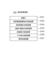
図6は回転角度タイムラインの一例を示す図である。この例では、バイアル110は以下のように回転させられる。
区間1(時刻t0-t1):正立した姿勢で静止
区間2(時刻t1-t2):回転軸Aを軸に360°回転。
区間3(時刻t2-t3):回転軸Bを軸に95°回転。
区間4(時刻t3-t4):区間3の姿勢で静止
区間5(時刻t4-t5):回転軸Bを軸に-5°回転。
区間6(時刻t5-t6):区間5すなわち横倒しの姿勢で回転軸Aを軸に-180°回転。
区間7(時刻t6-t7):横倒しの姿勢で回転軸Aを軸に180°回転。
区間8(時刻t7-t9):回転軸Bを軸に-170°回転した後、直ちに80°回転。
区間9(時刻t9-t10):区間1と同じ姿勢で静止。
区間10(時刻t10-t11):回転軸Aを軸に-360°回転。
区間11(時刻t11-t12):区間1と同じ姿勢で静止。
区間2の回転軸Aの回転角度はバイアル径とバイアル側面のガラスの厚みによっては360°回転させる必要はなく360°より小さな値例えば355°であってもよい。この場合、区間10の回転角度は区間2で回転した角度分戻る角度になる。また、区間8の回転軸Bの回転角度はバイアル径や充填された内容液量によって変化させてもよい。 6 is a diagram showing an example of a rotation angle timeline. In this example, thevial 110 is rotated as follows:
Interval 1 (time t0-t1): Stationary in an upright position Interval 2 (time t1-t2): Rotates 360° around rotation axis A.
Section 3 (time t2-t3): Rotate 95° around rotation axis B.
Section 4 (time t3-t4): Stationary in the posture of section 3 Section 5 (time t4-t5): Rotated -5° around rotation axis B.
Section 6 (time t5-t6): Section 5, i.e., rotation -180° around rotation axis A in a sideways position.
Section 7 (time t6-t7): Rotate 180° around rotation axis A in a sideways position.
Section 8 (time t7-t9): After rotating -170° around rotation axis B, immediately rotate 80°.
Section 9 (time t9-t10): Stationary in the same position as section 1.
Section 10 (time t10-t11): Rotate -360° around rotation axis A.
Section 11 (time t11-t12): Stationary in the same position as in section 1.
The rotation angle of rotation axis A in section 2 does not need to be 360° depending on the vial diameter and the thickness of the glass on the side of the vial, and may be a value smaller than 360°, for example, 355°. In this case, the rotation angle in section 10 is an angle that returns the angle rotated in section 2. Furthermore, the rotation angle of rotation axis B in section 8 may be changed depending on the vial diameter and the amount of liquid content filled.
区間1(時刻t0-t1):正立した姿勢で静止
区間2(時刻t1-t2):回転軸Aを軸に360°回転。
区間3(時刻t2-t3):回転軸Bを軸に95°回転。
区間4(時刻t3-t4):区間3の姿勢で静止
区間5(時刻t4-t5):回転軸Bを軸に-5°回転。
区間6(時刻t5-t6):区間5すなわち横倒しの姿勢で回転軸Aを軸に-180°回転。
区間7(時刻t6-t7):横倒しの姿勢で回転軸Aを軸に180°回転。
区間8(時刻t7-t9):回転軸Bを軸に-170°回転した後、直ちに80°回転。
区間9(時刻t9-t10):区間1と同じ姿勢で静止。
区間10(時刻t10-t11):回転軸Aを軸に-360°回転。
区間11(時刻t11-t12):区間1と同じ姿勢で静止。
区間2の回転軸Aの回転角度はバイアル径とバイアル側面のガラスの厚みによっては360°回転させる必要はなく360°より小さな値例えば355°であってもよい。この場合、区間10の回転角度は区間2で回転した角度分戻る角度になる。また、区間8の回転軸Bの回転角度はバイアル径や充填された内容液量によって変化させてもよい。 6 is a diagram showing an example of a rotation angle timeline. In this example, the
Interval 1 (time t0-t1): Stationary in an upright position Interval 2 (time t1-t2): Rotates 360° around rotation axis A.
Section 3 (time t2-t3): Rotate 95° around rotation axis B.
Section 4 (time t3-t4): Stationary in the posture of section 3 Section 5 (time t4-t5): Rotated -5° around rotation axis B.
Section 6 (time t5-t6): Section 5, i.e., rotation -180° around rotation axis A in a sideways position.
Section 7 (time t6-t7): Rotate 180° around rotation axis A in a sideways position.
Section 8 (time t7-t9): After rotating -170° around rotation axis B, immediately rotate 80°.
Section 9 (time t9-t10): Stationary in the same position as section 1.
Section 10 (time t10-t11): Rotate -360° around rotation axis A.
Section 11 (time t11-t12): Stationary in the same position as in section 1.
The rotation angle of rotation axis A in section 2 does not need to be 360° depending on the vial diameter and the thickness of the glass on the side of the vial, and may be a value smaller than 360°, for example, 355°. In this case, the rotation angle in section 10 is an angle that returns the angle rotated in section 2. Furthermore, the rotation angle of rotation axis B in section 8 may be changed depending on the vial diameter and the amount of liquid content filled.
バイアル110が図6に示す回転角度タイムラインにそって回転させられる場合、取得部542は、例えば、時刻t0において、照明装置300-1、300-2に対して点灯指令を送出すると共にカメラ装置400-1、400-2に対して撮影開始指令を送出し、時刻t12において、照明装置300-1、300-2に対して消灯指令を送出すると共にカメラ装置400-1、400-2に対して撮影終了指令を送出する。これにより、図6の回転角度タイムラインの全区間でカメラ装置400-1、400-2によるバイアル110の撮影が行われる。但し、一部の区間に限定してカメラ装置400-1、400-2による撮影を行うようにしてもよい。
When the vial 110 is rotated along the rotation angle timeline shown in FIG. 6, the acquisition unit 542, for example, at time t0, sends a turn-on command to the lighting devices 300-1 and 300-2 and a start image capture command to the camera devices 400-1 and 400-2, and at time t12, sends a turn-off command to the lighting devices 300-1 and 300-2 and a stop image capture command to the camera devices 400-1 and 400-2. This causes the camera devices 400-1 and 400-2 to capture images of the vial 110 over the entire section of the rotation angle timeline in FIG. 6. However, image capture by the camera devices 400-1 and 400-2 may be limited to a certain section.
図7は、区間2および区間10において、カメラ装置400-1およびカメラ装置400-2によって正立姿勢のバイアル110を撮影する様子を示す模式図である。区間2では、バイアル110は、正立姿勢で回転軸Aを軸に360°回転し、区間10では、バイアル110は、正立姿勢で回転軸Aを軸に-360°回転する。カメラ装置400-1は、これらの回転中のバイアル110の瓶胴部を回転軸Aに垂直な方向から撮影し、カメラ装置400-2は、これらの回転中のバイアル110を回転軸Aに平行な方向からバイアル110の瓶底部側から撮影する。
FIG. 7 is a schematic diagram showing how the upright vial 110 is photographed by camera device 400-1 and camera device 400-2 in sections 2 and 10. In section 2, the vial 110 rotates 360° around rotation axis A in an upright position, and in section 10, the vial 110 rotates -360° around rotation axis A in an upright position. Camera device 400-1 photographs the body of the rotating vial 110 from a direction perpendicular to rotation axis A, and camera device 400-2 photographs the rotating vial 110 from the bottom side of the vial 110 in a direction parallel to rotation axis A.
図8は、区間6および区間7において、カメラ装置400-1およびカメラ装置400-2によって横倒し姿勢のバイアル110を撮影する様子を示す模式図である。区間6および区間7では、バイアル110は、横倒しの姿勢で回転軸Aを軸に-180°および180°回転する。カメラ装置400-1は、この回転中のバイアル110の瓶胴部を回転軸Aに垂直な方向から撮影する。一方、カメラ装置400-2は、この回転中のバイアル110を回転軸Aに平行な方向且つ瓶底部側から撮影する。
FIG. 8 is a schematic diagram showing how the vial 110 in a sideways position is photographed by camera device 400-1 and camera device 400-2 in sections 6 and 7. In sections 6 and 7, the vial 110 in a sideways position rotates -180° and 180° around rotation axis A. Camera device 400-1 photographs the body of the rotating vial 110 from a direction perpendicular to rotation axis A. Meanwhile, camera device 400-2 photographs the rotating vial 110 from a direction parallel to rotation axis A and from the bottom side of the vial.
続いて、バイアル110が図6に示す回転角度タイムラインに沿って回転しているときにカメラ装置400によって撮影して得られた画像に基づいて、瓶胴部固着異物、瓶胴部傷、蓋裏付着物、底面傷などを検査する方法の一例について説明する。
Next, we will explain an example of a method for inspecting for foreign objects stuck to the bottle body, scratches on the bottle body, objects attached to the back of the lid, scratches on the bottom surface, etc., based on images captured by the camera device 400 while the vial 110 is rotating along the rotation angle timeline shown in Figure 6.
<瓶胴部固着異物、瓶胴部傷の検査>
本願発明者は、バイアルの瓶胴部内壁に張り付いた異物の検査方法を探求する過程で、次のような現象を発見した。即ち、バイアルを横倒しの姿勢で中心軸を中心に瓶胴部内壁に張り付いた異物が液中と液外の境界を通過するように回転させると、瓶胴部内壁に張り付いた異物の位置が少し変化する現象が確認された。また、バイアルの瓶胴部内壁に張り付いた異物は主に繊維片であるが、上記のように回転させると、張り付いた繊維片の形状が変化する現象が確認された。このような現象が起きる理由として、上記回転によって、バイアルの瓶胴部内壁に張り付いた異物が、液中と液外の境界を通過する際に液面の表面張力に引っ張られることが考えられる。前述したようにバイアルに充填される液体の量はバイアルの容量の略半分であるため、図8に示されるように、横倒しの姿勢のバイアル110の液面高さRは瓶胴部の略中央付近になり、瓶胴部内壁の下半分は液中になり、上半分は液外になる。この状態でバイアル110を、回転軸Aを軸に-180°以上回転させると、瓶胴部内壁に張り付いた異物は回転に応じて液中と液外の境界を通過することになり、その際に液面の表面張力の影響を受ける。また、バイアル110を横倒しの姿勢で回転軸Aを軸に回転させることにより、バイアル110の蓋裏や底面に張り付いた異物も回転に応じて液中と液外の境界を通過する。そのため、瓶胴部内壁に張り付いた異物だけでなく、蓋裏や底面に張り付いた異物の位置や形状も変化することが期待される。なお、バイアル110を横倒しの姿勢で中心軸を中心に回転させると、内壁に張り付いた異物が完全に剥離し、あるいは液中を浮遊していた異物が内壁に新たに張り付くことがあり得る。この場合、剥離する前の異物および新たに張り付いた異物も、回転前後ともに張り付いたままの異物と同様に回転前後の画像の差分として検出されることになる。 <Inspection for foreign objects stuck to bottle bodies and scratches on bottle bodies>
The inventor of the present application discovered the following phenomenon in the process of searching for a method of inspecting foreign matter stuck to the inner wall of the vial. That is, when the vial is turned on its side and rotated around the central axis so that the foreign matter stuck to the inner wall of the vial passes through the boundary between inside and outside the liquid, the position of the foreign matter stuck to the inner wall of the vial changes slightly. In addition, the foreign matter stuck to the inner wall of the vial is mainly fiber pieces, and when the vial is rotated as described above, the shape of the stuck fiber pieces changes. The reason for this phenomenon is considered to be that the foreign matter stuck to the inner wall of the vial is pulled by the surface tension of the liquid surface when passing through the boundary between inside and outside the liquid due to the rotation. As described above, the amount of liquid filled in the vial is approximately half the capacity of the vial, so that the liquid level height R of thevial 110 in the turned-over position is approximately near the center of the bottle body, and the lower half of the inner wall of the bottle body is in the liquid and the upper half is outside the liquid, as shown in FIG. 8. In this state, when the vial 110 is rotated about the rotation axis A by −180° or more, the foreign matter attached to the inner wall of the bottle body passes through the boundary between the inside and outside of the liquid as it rotates, and is affected by the surface tension of the liquid surface. In addition, when the vial 110 is rotated about the rotation axis A in a sideways position, the foreign matter attached to the back of the lid or the bottom of the vial 110 also passes through the boundary between the inside and outside of the liquid as it rotates. Therefore, it is expected that not only the foreign matter attached to the inner wall of the bottle body, but also the position and shape of the foreign matter attached to the back of the lid or the bottom will change. In addition, when the vial 110 is rotated about the central axis in a sideways position, the foreign matter attached to the inner wall may be completely peeled off, or the foreign matter floating in the liquid may newly stick to the inner wall. In this case, the foreign matter before peeling off and the newly attached foreign matter will be detected as the difference between the images before and after rotation, as well as the foreign matter that remains attached before and after rotation.
本願発明者は、バイアルの瓶胴部内壁に張り付いた異物の検査方法を探求する過程で、次のような現象を発見した。即ち、バイアルを横倒しの姿勢で中心軸を中心に瓶胴部内壁に張り付いた異物が液中と液外の境界を通過するように回転させると、瓶胴部内壁に張り付いた異物の位置が少し変化する現象が確認された。また、バイアルの瓶胴部内壁に張り付いた異物は主に繊維片であるが、上記のように回転させると、張り付いた繊維片の形状が変化する現象が確認された。このような現象が起きる理由として、上記回転によって、バイアルの瓶胴部内壁に張り付いた異物が、液中と液外の境界を通過する際に液面の表面張力に引っ張られることが考えられる。前述したようにバイアルに充填される液体の量はバイアルの容量の略半分であるため、図8に示されるように、横倒しの姿勢のバイアル110の液面高さRは瓶胴部の略中央付近になり、瓶胴部内壁の下半分は液中になり、上半分は液外になる。この状態でバイアル110を、回転軸Aを軸に-180°以上回転させると、瓶胴部内壁に張り付いた異物は回転に応じて液中と液外の境界を通過することになり、その際に液面の表面張力の影響を受ける。また、バイアル110を横倒しの姿勢で回転軸Aを軸に回転させることにより、バイアル110の蓋裏や底面に張り付いた異物も回転に応じて液中と液外の境界を通過する。そのため、瓶胴部内壁に張り付いた異物だけでなく、蓋裏や底面に張り付いた異物の位置や形状も変化することが期待される。なお、バイアル110を横倒しの姿勢で中心軸を中心に回転させると、内壁に張り付いた異物が完全に剥離し、あるいは液中を浮遊していた異物が内壁に新たに張り付くことがあり得る。この場合、剥離する前の異物および新たに張り付いた異物も、回転前後ともに張り付いたままの異物と同様に回転前後の画像の差分として検出されることになる。 <Inspection for foreign objects stuck to bottle bodies and scratches on bottle bodies>
The inventor of the present application discovered the following phenomenon in the process of searching for a method of inspecting foreign matter stuck to the inner wall of the vial. That is, when the vial is turned on its side and rotated around the central axis so that the foreign matter stuck to the inner wall of the vial passes through the boundary between inside and outside the liquid, the position of the foreign matter stuck to the inner wall of the vial changes slightly. In addition, the foreign matter stuck to the inner wall of the vial is mainly fiber pieces, and when the vial is rotated as described above, the shape of the stuck fiber pieces changes. The reason for this phenomenon is considered to be that the foreign matter stuck to the inner wall of the vial is pulled by the surface tension of the liquid surface when passing through the boundary between inside and outside the liquid due to the rotation. As described above, the amount of liquid filled in the vial is approximately half the capacity of the vial, so that the liquid level height R of the
そこで、本実施形態では、バイアル110を、横倒し姿勢で回転軸Aを軸に回転させる区間6および区間7の前と後にカメラ装置400-1によってバイアル110の瓶胴部の同一の領域をそれぞれ撮影して得られる回転前の画像および回転後の画像を比較することにより、瓶胴部固着異物、瓶胴部傷などを区別して検出する。
In this embodiment, therefore, the camera device 400-1 photographs the same area of the vial body of the vial 110 before and after sections 6 and 7 in which the vial 110 is rotated around rotation axis A in a sideways position, and the images obtained before and after the rotation are compared to distinguish and detect foreign objects stuck to the bottle body, scratches on the bottle body, etc.
図9は、検出部543が瓶胴部固着異物および瓶胴部傷を検出する処理の一例を示すフローチャートである。図9を参照すると、検出部543は、図3に示される画像情報532から、カメラ装置400-1のカメラID5322と区間2に含まれる撮影時刻5323とを含むエントリを第1エントリとして全て取得する(ステップS11)。この第1エントリに含まれるフレーム画像が、上述した回転前の画像に相当する。また、検出部543は、図3に示される画像情報532から、カメラ装置400-1のカメラID5322と区間10に含まれる撮影時刻5323とを含むエントリを第2エントリとして全て取得する(ステップS12)。この第2エントリに含まれるフレーム画像が、上述した回転後の画像に相当する。
FIG. 9 is a flow chart showing an example of a process in which the detection unit 543 detects foreign matter stuck to the bottle body and scratches on the bottle body. Referring to FIG. 9, the detection unit 543 acquires all entries including the camera ID 5322 of the camera device 400-1 and the shooting time 5323 included in section 2 as first entries from the image information 532 shown in FIG. 3 (step S11). The frame image included in this first entry corresponds to the image before rotation described above. The detection unit 543 also acquires all entries including the camera ID 5322 of the camera device 400-1 and the shooting time 5323 included in section 10 as second entries from the image information 532 shown in FIG. 3 (step S12). The frame image included in this second entry corresponds to the image after rotation described above.
次に、検出部543は、回転軸Aの回転角5324が同一である第1エントリと第2エントリとの組を全て生成する(ステップS13)。次に、検出部543は、組の1つに注目し(ステップS14)、注目中の組の第1エントリのフレーム画像5326と第2エントリのフレーム画像5326とを比較し(ステップS15)、両フレーム画像で瓶胴部の画像が同一であるか、相違するかを判別する(ステップS16)。このステップS15、S16では、検出部543は、例えば、第1エントリのフレーム画像5326中の瓶胴部の画像と第2エントリのフレーム画像5326中の瓶胴部の画像との差分をとり、差分があれば相違すると判断し、差分がなければ同一であると判断してよい。但し、両フレーム画像の瓶胴部の画像が同一か相違するかを判別する方法は差分による方法に限定されず、他の任意の方法を使用してもよい。次に、検出部543は、両フレーム画像間に相違があるならば、それは瓶胴部固着異物に起因するものと判断し、瓶胴部固着異物カウンタ(初期値は0)をインクリメントする(ステップS17)。この例では、両フレーム画像間に相違があるときは直ちに瓶胴部固着異物であると判断している。しかし、両フレーム画像間に相違があるときに、相違する原因となったフレーム画像中の暗部の形状、色などの見た目の情報に基づいて、当該暗部が繊維片などの異物であるか、異物以外の液滴であるかを識別するようにしてもよい。
Next, the detection unit 543 generates all pairs of the first entry and the second entry in which the rotation angle 5324 of the rotation axis A is the same (step S13). Next, the detection unit 543 focuses on one of the pairs (step S14), compares the frame image 5326 of the first entry of the focused pair with the frame image 5326 of the second entry (step S15), and determines whether the images of the bottle body are the same or different in both frame images (step S16). In these steps S15 and S16, the detection unit 543 may, for example, take the difference between the image of the bottle body in the frame image 5326 of the first entry and the image of the bottle body in the frame image 5326 of the second entry, and determine that there is a difference and that there is no difference and that there is the same. However, the method of determining whether the images of the bottle body in both frame images are the same or different is not limited to the method based on the difference, and any other method may be used. Next, if there is a difference between the two frame images, the detection unit 543 determines that this is due to a foreign object stuck to the bottle body, and increments the foreign object stuck to the bottle body counter (initial value is 0) (step S17). In this example, when there is a difference between the two frame images, it is immediately determined that there is a foreign object stuck to the bottle body. However, when there is a difference between the two frame images, it may be possible to identify whether the dark area is a foreign object such as a piece of fiber, or a liquid droplet other than a foreign object, based on information on the appearance, such as the shape and color, of the dark area in the frame image that caused the difference.
一方、両フレーム画像間に相違がないときは、検出部543は、注目中の組の第1エントリまたは第2エントリのフレーム画像の瓶胴部の画像中に閾値サイズ以上のサイズの暗部が存在するか否かを判別する(ステップS18)。なお、瓶胴部の画像には、瓶の壁やその付近が暗部として写っているので、それ以外の箇所(瓶胴部の中央部分など)に閾値サイズ以上のサイズの暗部が存在するか否かを判別するようにしてよい。検出部543は、閾値サイズ以上のサイズの暗部が存在するならば、その暗部は許容できないサイズの瓶胴部の傷であると判断し、瓶胴部傷カウンタ(初期値は0)をインクリメントする(ステップS19)。閾値サイズは、ミリメートルオーダーである。これは、ミリメートルオーダー未満の傷は問題とされないためである。
On the other hand, when there is no difference between the two frame images, the detection unit 543 determines whether or not there is a dark area of a size equal to or larger than the threshold size in the image of the bottle body of the frame image of the first entry or the second entry of the pair under consideration (step S18). Note that since the image of the bottle body shows the bottle wall and its vicinity as dark areas, it may be possible to determine whether or not there is a dark area of a size equal to or larger than the threshold size in other locations (such as the center of the bottle body). If there is a dark area of a size equal to or larger than the threshold size, the detection unit 543 determines that the dark area is a scratch on the bottle body of an unacceptable size, and increments the bottle body scratch counter (initial value is 0) (step S19). The threshold size is on the order of millimeters. This is because scratches smaller than the order of millimeters are not considered a problem.
次に、検出部543は、次の1つの組に注目を移し(ステップS20、S21)、ステップS15に戻って、上述した処理と同様の処理を繰り返す。そして、検出部543は、必要な組すべてに注目し終えると(ステップS21でYES)、検査結果情報533を更新する(ステップS22)。ステップS21における「必要な組」とは、例えば全領域が手前側に見えるだけの最小枚数の組としてよい。このステップS22では、検出部543は、検査対象のバイアル110の容器ID5331が設定された検査結果情報533の瓶胴部固着異物の検査結果5332および瓶胴部傷の検査結果5333を更新する。検出部543は、瓶胴部固着異物の検査結果5332の更新では、瓶胴部固着異物カウンタの値が1以上であれば、NG(検査不合格)を設定し、1未満であればOK(検査合格)を設定する。また、検出部543は、瓶胴部傷の検査結果5333の更新では、瓶胴部傷カウンタの値が1以上であれば、NG(検査不合格)を設定し、1未満であればOK(検査合格)を設定する。なお、瓶胴部固着異物の数の大小の目安となる瓶胴部固着異物カウンタの値を瓶胴部固着異物の検査結果5332に保存するようにしてもよい。同様に、瓶胴部傷の数の大小の目安となる瓶胴部傷カウンタの値を瓶胴部傷の検査結果5333に保存するようにしてもよい。
Next, the detection unit 543 shifts its attention to the next pair (steps S20, S21), returns to step S15, and repeats the same process as described above. Then, when the detection unit 543 has finished paying attention to all the necessary pairs (YES in step S21), it updates the inspection result information 533 (step S22). The "necessary pair" in step S21 may be, for example, a pair of the minimum number of sheets in which the entire area is visible in front. In this step S22, the detection unit 543 updates the inspection result 5332 for foreign matter stuck to the bottle body and the inspection result 5333 for damage to the bottle body in the inspection result information 533 in which the container ID 5331 of the vial 110 to be inspected is set. In updating the inspection result 5332 for foreign matter stuck to the bottle body, if the value of the counter for foreign matter stuck to the bottle body is 1 or more, the detection unit 543 sets NG (inspection failed) and if it is less than 1, sets OK (inspection passed). Furthermore, when updating the bottle body damage inspection results 5333, the detection unit 543 sets NG (inspection failed) if the value of the bottle body damage counter is 1 or more, and sets OK (inspection passed) if it is less than 1. Note that the value of the bottle body stuck foreign matter counter, which is a measure of the number of foreign matter stuck to the bottle body, may be stored in the bottle body stuck foreign matter inspection results 5332. Similarly, the value of the bottle body damage counter, which is a measure of the number of scratches on the bottle body, may be stored in the bottle body damage inspection results 5333.
図9に示した例では、必要な組すべてについて処理を繰り返しているが、瓶胴部固着異物カウンタまたは/および瓶胴部傷カウンタが1以上の値になった時点で、直ちにステップS22を実行し、その後に図9の処理を終了するようにしてもよい。
In the example shown in FIG. 9, the process is repeated for all necessary pairs, but it is also possible to execute step S22 immediately when the bottle body adhered foreign matter counter and/or the bottle body scratch counter reach a value of 1 or more, and then terminate the process of FIG. 9.
<蓋裏付着物>
上述したように、バイアル110に充填される液体の量はバイアル110の容量の略半分である。そのため、図8に示されるように、横倒しの姿勢のバイアル110の液面は瓶胴部の略中央になり、瓶胴部内の少なくとも上半分は液体が存在しない状態になる。カメラ装置400-2は、このような状態のバイアル110を回転軸Aに平行な方向且つ瓶底部側から撮影する。従って、カメラ装置400-2は、バイアル110の蓋の裏の一部を、液中を通さずに(従って、液中に存在する気泡の影響を受けずに)撮影することができる。換言すれば、カメラ装置400-2で撮影された画像には、液中を通さずに撮影されたバイアル110の蓋の裏の一部が写っている。バイアル110が静止した状態では、液中を通さずに撮影できる蓋の裏の範囲は一部に限定される。しかし、区間6および区間7では、バイアル110を、回転軸Aを軸に-180°回転させた後に180度回転させ、その回転中にカメラ装置400-2が撮影を行っている。そのため、カメラ装置400-2によって区間6または/および区間7で撮影された複数枚のフレーム画像を集めれば、蓋の裏全体を、液中を通さずに観察することができる。検出部543は、上記のように液中を通さずに撮影されたバイアル110の蓋の裏の画像に基づいて、蓋裏付着物を検出する。 <Deposits on the back of the lid>
As described above, the amount of liquid filled in thevial 110 is approximately half the capacity of the vial 110. Therefore, as shown in FIG. 8, the liquid level of the vial 110 in the lying position is approximately at the center of the bottle body, and at least the upper half of the bottle body is in a state where no liquid exists. The camera device 400-2 photographs the vial 110 in such a state from the direction parallel to the rotation axis A and from the bottle bottom side. Therefore, the camera device 400-2 can photograph a part of the back of the lid of the vial 110 without passing through the liquid (and therefore without being affected by air bubbles present in the liquid). In other words, the image photographed by the camera device 400-2 shows a part of the back of the lid of the vial 110 photographed without passing through the liquid. When the vial 110 is stationary, the range of the back of the lid that can be photographed without passing through the liquid is limited to a part. However, in sections 6 and 7, the vial 110 is rotated -180° around the rotation axis A and then rotated 180°, and the camera device 400-2 captures images during the rotation. Therefore, by collecting multiple frame images captured by the camera device 400-2 in sections 6 and/or 7, the entire back of the lid can be observed without passing through liquid. The detection unit 543 detects the matter adhering to the back of the lid based on the images of the back of the lid of the vial 110 captured without passing through liquid as described above.
上述したように、バイアル110に充填される液体の量はバイアル110の容量の略半分である。そのため、図8に示されるように、横倒しの姿勢のバイアル110の液面は瓶胴部の略中央になり、瓶胴部内の少なくとも上半分は液体が存在しない状態になる。カメラ装置400-2は、このような状態のバイアル110を回転軸Aに平行な方向且つ瓶底部側から撮影する。従って、カメラ装置400-2は、バイアル110の蓋の裏の一部を、液中を通さずに(従って、液中に存在する気泡の影響を受けずに)撮影することができる。換言すれば、カメラ装置400-2で撮影された画像には、液中を通さずに撮影されたバイアル110の蓋の裏の一部が写っている。バイアル110が静止した状態では、液中を通さずに撮影できる蓋の裏の範囲は一部に限定される。しかし、区間6および区間7では、バイアル110を、回転軸Aを軸に-180°回転させた後に180度回転させ、その回転中にカメラ装置400-2が撮影を行っている。そのため、カメラ装置400-2によって区間6または/および区間7で撮影された複数枚のフレーム画像を集めれば、蓋の裏全体を、液中を通さずに観察することができる。検出部543は、上記のように液中を通さずに撮影されたバイアル110の蓋の裏の画像に基づいて、蓋裏付着物を検出する。 <Deposits on the back of the lid>
As described above, the amount of liquid filled in the
図10は、検出部543が蓋裏付着物を検出する処理の一例を示すフローチャートである。図10を参照すると、検出部543は、図3に示される画像情報532から、カメラ装置400-2のカメラID5322と区間6または/および区間7に含まれる撮影時刻5323とを含むエントリを全て取得する(ステップS31)。次に、検出部543は、1つのエントリに注目する(ステップS32)。次に、検出部543は、注目中のエントリのフレーム画像5326と記憶部530に保存されている基準画像(図示せず)とを比較し(ステップS33)、両画像が同一であるか、相違するかを判別する(ステップS34)。バイアル110の蓋の裏の形状および色は、バイアルの種類毎に定まっている。基準画像は、検査対象のバイアル110と同じ種類であって蓋裏付着物がない状態のバイアルの蓋裏をカメラ装置400-2で事前に撮影して記憶部530に保存されている。ステップS33では、検出部543は、例えば、フレーム画像5326と基準画像との差分をとり、差分があれば相違すると判断し、差分がなければ同一であると判断してよい。基準画像と差分をとるフレーム画像5326の範囲は、フレーム画像5326の全体であってもよいし、フレーム画像5326中の蓋裏の全範囲であってもよいし、液体を介さずに撮影された蓋裏の範囲に限定してもよい。また、フレーム画像5326と基準画像が同一か相違するかを判別する方法は差分による方法に限定されず、他の任意の方法を使用してもよい。
10 is a flow chart showing an example of a process in which the detection unit 543 detects a lid back attachment. Referring to FIG. 10, the detection unit 543 acquires all entries including the camera ID 5322 of the camera device 400-2 and the shooting time 5323 included in section 6 or/and section 7 from the image information 532 shown in FIG. 3 (step S31). Next, the detection unit 543 focuses on one entry (step S32). Next, the detection unit 543 compares the frame image 5326 of the entry being focused on with a reference image (not shown) stored in the storage unit 530 (step S33) and determines whether the two images are the same or different (step S34). The shape and color of the back of the lid of the vial 110 are determined for each type of vial. The reference image is a previously captured image of the back of the lid of a vial of the same type as the vial 110 to be inspected, without a lid back attachment, by the camera device 400-2 and stored in the storage unit 530. In step S33, the detection unit 543 may, for example, take the difference between the frame image 5326 and the reference image, and determine that they are different if there is a difference, and that they are the same if there is no difference. The range of the frame image 5326 from which the difference with the reference image is taken may be the entire frame image 5326, may be the entire range of the lid back in the frame image 5326, or may be limited to the range of the lid back photographed without liquid. Furthermore, the method of determining whether the frame image 5326 and the reference image are the same or different is not limited to the method based on the difference, and any other method may be used.
次に、検出部543は、フレーム画像5326と基準画像間に相違があるならば、それは蓋裏付着物に起因するものと判断し、蓋裏付着物カウンタ(初期値は0)をインクリメントする(ステップS35)。この例では、フレーム画像5326と基準画像間に相違があるときは直ちに蓋裏付着物であると判断している。しかし、フレーム画像5326と基準画像間に相違があるときに、相違する箇所(差分箇所)近傍の形状、色などの見た目の情報に基づいて、当該差分箇所に異物が実際にあるか、異物以外の液滴であるかなどを識別するようにしてもよい。
Next, if there is a difference between frame image 5326 and the reference image, detection unit 543 determines that this is due to a lid back attachment, and increments the lid back attachment counter (initial value is 0) (step S35). In this example, when there is a difference between frame image 5326 and the reference image, it is immediately determined that there is a lid back attachment. However, when there is a difference between frame image 5326 and the reference image, it may be possible to determine whether there is actually a foreign object at the difference point, or whether it is a droplet other than a foreign object, based on appearance information such as the shape and color near the difference point (difference point).
一方、フレーム画像5326と基準画像間に相違がないときは、検出部543は、ステップS35をスキップする。次に、検出部543は、次の1つのエントリに注目を移し(ステップS36、S37)、ステップS33に戻って、上述した処理と同様の処理を繰り返す。そして、検出部543は、全てのエントリに注目し終えると(ステップS37でYES)、検査結果情報533を更新する(ステップS38)。このステップS38では、検出部543は、検査対象のバイアル110の容器ID5331が設定された検査結果情報533の蓋裏付着物の検査結果5334を更新する。検出部543は、蓋裏付着物の検査結果5334の更新では、蓋裏付着物カウンタの値が1以上であれば、NG(検査不合格)を設定し、1未満であればOK(検査合格)を設定する。なお、蓋裏付着物の数の目安となる蓋裏付着物カウンタの値を蓋裏付着物の検査結果5334に保存するようにしてもよい。
On the other hand, when there is no difference between the frame image 5326 and the reference image, the detection unit 543 skips step S35. Next, the detection unit 543 shifts its attention to the next entry (steps S36, S37), returns to step S33, and repeats the same process as described above. Then, when the detection unit 543 has finished paying attention to all entries (YES in step S37), it updates the inspection result information 533 (step S38). In this step S38, the detection unit 543 updates the inspection result 5334 of the lid back attachment in the inspection result information 533 in which the container ID 5331 of the vial 110 to be inspected is set. In updating the inspection result 5334 of the lid back attachment, if the value of the lid back attachment counter is 1 or more, the detection unit 543 sets NG (inspection failed) and if it is less than 1, sets OK (inspection passed). Note that the value of the lid back attachment counter, which is an indication of the number of lid back attachments, may be saved in the lid back attachment inspection result 5334.
図10に示した例では、全てのエントリについて処理を繰り返しているが、蓋裏付着物カウンタが1以上の値になった時点で、直ちにステップS38を実行し、その後に図10の処理を終了するようにしてもよい。
In the example shown in Figure 10, the process is repeated for all entries, but it is also possible to execute step S38 immediately when the lid back deposit counter reaches a value of 1 or more, and then terminate the process of Figure 10.
<底面傷、底面異物の検査>
図11は、検出部543が底面傷および底面異物を検出する処理の一例を示すフローチャートである。図11を参照すると、検出部543は、図3に示される画像情報532から、カメラ装置400-2のカメラID5322と区間2に含まれる撮影時刻5323とを含むエントリを第1エントリとして全て取得する(ステップS41)。この第1エントリに含まれるフレーム画像は、バイアル110を、横倒しの姿勢で回転軸Aを軸に回転させる前にカメラ装置400-2によってバイアル110を瓶底部側から撮影して得られる画像に相当する。また、検出部543は、図3に示される画像情報532から、カメラ装置400-2のカメラID5322と区間10に含まれる撮影時刻5323とを含むエントリを第2エントリとして全て取得する(ステップS42)。この第2エントリに含まれるフレーム画像は、バイアル110を、横倒しの姿勢で回転軸Aを軸に回転させた後にカメラ装置400-2によってバイアル110を瓶底部側から撮影して得られる画像に相当する。 <Inspection for bottom scratches and foreign objects>
FIG. 11 is a flowchart showing an example of a process in which thedetection unit 543 detects bottom scratches and bottom foreign objects. Referring to FIG. 11, the detection unit 543 acquires all entries including the camera ID 5322 of the camera device 400-2 and the shooting time 5323 included in the section 2 as first entries from the image information 532 shown in FIG. 3 (step S41). The frame image included in this first entry corresponds to an image obtained by photographing the vial 110 from the bottle bottom side by the camera device 400-2 before rotating the vial 110 around the rotation axis A in a sideways position. In addition, the detection unit 543 acquires all entries including the camera ID 5322 of the camera device 400-2 and the shooting time 5323 included in the section 10 as second entries from the image information 532 shown in FIG. 3 (step S42). The frame image included in this second entry corresponds to an image obtained by rotating vial 110 on its side about rotation axis A and then photographing vial 110 from the bottom side with camera device 400-2.
図11は、検出部543が底面傷および底面異物を検出する処理の一例を示すフローチャートである。図11を参照すると、検出部543は、図3に示される画像情報532から、カメラ装置400-2のカメラID5322と区間2に含まれる撮影時刻5323とを含むエントリを第1エントリとして全て取得する(ステップS41)。この第1エントリに含まれるフレーム画像は、バイアル110を、横倒しの姿勢で回転軸Aを軸に回転させる前にカメラ装置400-2によってバイアル110を瓶底部側から撮影して得られる画像に相当する。また、検出部543は、図3に示される画像情報532から、カメラ装置400-2のカメラID5322と区間10に含まれる撮影時刻5323とを含むエントリを第2エントリとして全て取得する(ステップS42)。この第2エントリに含まれるフレーム画像は、バイアル110を、横倒しの姿勢で回転軸Aを軸に回転させた後にカメラ装置400-2によってバイアル110を瓶底部側から撮影して得られる画像に相当する。 <Inspection for bottom scratches and foreign objects>
FIG. 11 is a flowchart showing an example of a process in which the
次に、検出部543は、回転軸Aの回転角5324が同一である第1エントリと第2エントリとの組を生成する(ステップS43)。次に、検出部543は、組の1つに注目し(ステップS44)、注目中の組の第1エントリのフレーム画像5326と第2エントリのフレーム画像5326とを比較し(ステップS45)、両フレーム画像が同一であるか、相違するかを判別する(ステップS46)。ステップS45では、検出部543は、例えば、第1エントリのフレーム画像5326中の瓶底部の画像と第2エントリのフレーム画像5326中の瓶底部の画像との差分をとり、差分があれば相違すると判断し、差分がなければ同一であると判断してよい。但し、両フレーム画像の瓶底部の画像が同一か相違するかを判別する方法は差分による方法に限定されず、他の任意の方法を使用してもよい。次に、検出部543は、両フレーム画像間に相違があるならば、それはバイアル110の底面に沈殿ないし張り付いた異物に起因するものと判断し、底面異物カウンタ(初期値は0)をインクリメントする(ステップS47)。この例では、両フレーム画像間に相違があるときは直ちに底面異物であると判断している。しかし、両フレーム画像間に相違があるときに、相違する原因となったフレーム画像の暗部の形状、色などの見た目の情報に基づいて、当該暗部が金属片や繊維片などの異物であるか、異物以外の巨大な泡であるかを識別するようにしてもよい。
Next, the detection unit 543 generates a pair of a first entry and a second entry in which the rotation angle 5324 of the rotation axis A is the same (step S43). Next, the detection unit 543 focuses on one of the pairs (step S44), compares the frame image 5326 of the first entry of the focused pair with the frame image 5326 of the second entry (step S45), and determines whether the two frame images are the same or different (step S46). In step S45, the detection unit 543 may, for example, take the difference between the image of the bottle bottom in the frame image 5326 of the first entry and the image of the bottle bottom in the frame image 5326 of the second entry, and determine that there is a difference and that there is no difference and that there is the same. However, the method of determining whether the images of the bottle bottom in both frame images are the same or different is not limited to the method based on the difference, and any other method may be used. Next, if there is a difference between the two frame images, the detection unit 543 determines that this is due to a foreign object that has settled or stuck to the bottom surface of the vial 110, and increments the bottom foreign object counter (initial value is 0) (step S47). In this example, when there is a difference between the two frame images, it is immediately determined that there is a bottom foreign object. However, when there is a difference between the two frame images, it may be possible to determine whether the dark part is a foreign object such as a piece of metal or fiber, or a large bubble other than a foreign object, based on appearance information such as the shape and color of the dark part of the frame image that caused the difference.
一方、両フレーム画像間に相違がないときは、検出部543は、注目中の組の第1エントリまたは第2エントリのフレーム画像に閾値サイズ以上のサイズの暗部が存在するか否かを判別する(ステップS48)。なお、瓶底部の画像には、瓶の壁やその付近が暗部として写っているので、それ以外の箇所(瓶底部の中央部分など)に閾値サイズ以上のサイズの暗部が存在するか否かを判別するようにしてよい。検出部543は、閾値サイズ以上のサイズの暗部が存在するならば、その暗部は許容できないサイズの底面傷であると判断し、底面傷カウンタ(初期値は0)をインクリメントする(ステップS49)。閾値サイズは、ミリメートルオーダーである。これは、ミリメートルオーダー未満の傷は問題とされないためである。
On the other hand, when there is no difference between the two frame images, the detection unit 543 determines whether or not a dark area of a size equal to or larger than the threshold size is present in the frame image of the first or second entry of the pair under consideration (step S48). Note that since the image of the bottom of the bottle shows the bottle wall and its vicinity as dark areas, it may be possible to determine whether or not a dark area of a size equal to or larger than the threshold size is present in other locations (such as the center of the bottom of the bottle). If a dark area of a size equal to or larger than the threshold size is present, the detection unit 543 determines that the dark area is a bottom scratch of an unacceptable size, and increments the bottom scratch counter (initial value is 0) (step S49). The threshold size is on the order of millimeters. This is because scratches smaller than the order of millimeters are not considered a problem.
次に、検出部543は、次の1つの組に注目を移し(ステップS50、S51)、ステップS45に戻って、上述した処理と同様の処理を繰り返す。そして、検出部543は、全ての組に注目し終えると(ステップS51でYES)、検査結果情報533を更新する(ステップS52)。このステップS52では、検出部543は、検査対象のバイアル110の容器ID5331が設定された検査結果情報533の底面傷の検査結果5335およびその他の検査結果5336を更新する。検出部543は、底面傷の検査結果5335の更新では、底面傷カウンタの値が1以上であれば、NG(検査不合格)を設定し、1未満であればOK(検査合格)を設定する。また、検出部543は、その他の検査結果5336の更新では、底面異物カウンタの値が1以上であれば、その他の検査結果5336に底面異物の検査項目を追加してNG(検査不合格)を設定し、1未満であればOK(検査合格)を設定する。なお、底面傷や底面異物の数の目安となる底面傷カウンタや底面異物カウントの値を底面傷の検査結果5335やその他の検査結果5336の底面異物の検査項目に保存するようにしてもよい。
Next, the detection unit 543 shifts its attention to the next pair (steps S50, S51), and returns to step S45 to repeat the same process as described above. Then, when the detection unit 543 has finished paying attention to all pairs (YES in step S51), it updates the inspection result information 533 (step S52). In this step S52, the detection unit 543 updates the bottom scratch inspection result 5335 and other inspection results 5336 of the inspection result information 533 in which the container ID 5331 of the vial 110 to be inspected is set. In updating the bottom scratch inspection result 5335, if the value of the bottom scratch counter is 1 or more, the detection unit 543 sets NG (inspection failed) and if it is less than 1, sets OK (inspection passed). Furthermore, when updating other inspection results 5336, if the value of the bottom foreign matter counter is 1 or more, the detection unit 543 adds an inspection item for bottom foreign matter to the other inspection results 5336 and sets NG (inspection failed), and if the value is less than 1, sets OK (inspection passed). Note that the values of the bottom scratch counter and bottom foreign matter count, which are indicators of the number of bottom scratches and bottom foreign matter, may be saved in the bottom scratch inspection result 5335 and the bottom foreign matter inspection item of the other inspection results 5336.
図11に示した例では、全ての組について処理を繰り返しているが、底面傷カウンタまたは/および底面異物カウンタが1以上の値になった時点で、直ちにステップS52を実行し、その後に図11の処理を終了するようにしてもよい。
In the example shown in FIG. 11, the process is repeated for all pairs, but it is also possible to execute step S52 immediately when the bottom scratch counter and/or bottom foreign object counter reach a value of 1 or more, and then terminate the process of FIG. 11.
以上説明したように本実施形態に係る検査システム100は、バイアル110を横倒し姿勢にしてその中心軸(回転軸A)を中心にバイアル110を回転させる工程を行う(図6の区間6または区間7)。これにより、バイアル110の内壁に張り付いた異物が、液中と液外の境界を通過する際に液面の表面張力に引っ張られることによって、異物の位置や形状が変化する現象が誘発される。即ち、バイアル110の内壁に張り付いた異物の位置を変化させることができる。そして、検査システム100は、上記工程が行われる前と後にカメラ装置400によってバイアル110の瓶胴部などの同一の所定領域をそれぞれ撮影して得られた回転前の画像(図6の区間2の画像)および回転後の画像(図6の区間10の画像)を取得する。そのため、回転前の画像と回転後の画像とを比較して、容器の内壁に付着した異物を検出する検出部543を設けることにより、上記工程を行っても位置や形状が変化しない傷と区別してバイアル110の内壁に張り付いた異物を検出することができる。
As described above, the inspection system 100 according to this embodiment performs a process of rotating the vial 110 around its central axis (rotation axis A) in a horizontal position (section 6 or section 7 in FIG. 6). This induces a phenomenon in which the position and shape of the foreign matter adhering to the inner wall of the vial 110 changes when the foreign matter passes through the boundary between inside and outside the liquid and is pulled by the surface tension of the liquid surface. That is, the position of the foreign matter adhering to the inner wall of the vial 110 can be changed. The inspection system 100 then obtains an image before rotation (image of section 2 in FIG. 6) and an image after rotation (image of section 10 in FIG. 6) obtained by photographing the same predetermined area of the vial 110, such as the bottle body, with the camera device 400 before and after the above process is performed. Therefore, by providing a detection unit 543 that compares the image before rotation and the image after rotation to detect the foreign matter adhering to the inner wall of the container, the foreign matter adhering to the inner wall of the vial 110 can be detected separately from scratches whose position and shape do not change even when the above process is performed.
また、本実施形態に係る検査システム100は、バイアル110を横倒し姿勢にしてその中心軸(回転軸A)を中心にバイアル110を回転させ、その中心軸(回転軸A)に平行な光軸を有するカメラ装置400-2によって回転中のバイアル110の底部側から液外の領域を通して蓋の裏側を撮影して得られた画像(図6の区間6または区間7の画像)を取得する。従って、カメラ装置400-2は、バイアル110の蓋の裏の一部を、液中を通さずに撮影することができる。即ち、カメラ装置400-2で撮影された画像には、液中を通さずに撮影されたバイアル110の蓋の裏の一部が写っている。その結果、蓋の裏に付着した異物を精度よく検出することができる。また、テレセントリックレンズを有するカメラ装置400-2を使用するため、液面をなるべく写さないように(画像中の液面輪郭部の厚みが薄くなるように)でき、また、カメラから一番離れた場所になる蓋裏を大きく写すことができる。
In addition, the inspection system 100 according to this embodiment rotates the vial 110 around its central axis (rotation axis A) while the vial 110 is in a sideways position, and acquires an image (an image of section 6 or section 7 in FIG. 6) of the back side of the lid of the rotating vial 110 through the area outside the liquid from the bottom side of the vial 110 using the camera device 400-2 having an optical axis parallel to the central axis (rotation axis A). Therefore, the camera device 400-2 can capture a part of the back side of the lid of the vial 110 without passing through the liquid. That is, the image captured by the camera device 400-2 captures a part of the back side of the lid of the vial 110 without passing through the liquid. As a result, foreign matter attached to the back side of the lid can be detected with high accuracy. In addition, the camera device 400-2 having a telecentric lens is used, so that the liquid surface is not captured as much as possible (so that the thickness of the liquid surface contour in the image is thin), and the back side of the lid, which is the farthest from the camera, can be captured in a large size.
本実施形態は、以下のような各種の付加変更が可能である。
This embodiment can be modified in various ways, such as:
バイアルを検査対象としたが、飲料水などの液体が充填された透明または半透明な容器であれば、バイアル以外の瓶や容器を検査対象とすることができる。
Although vials were the subject of the tests, bottles and containers other than vials can also be tested as long as they are transparent or translucent containers filled with liquids such as drinking water.
上記説明では、検査システム100は、図6の回転角度タイムラインにおける区間6、区間7において、バイアル110を、回転軸Aを中心に-180°回転(半回転)させた後に180°回転(半回転)させているが、それはあくまでも一例に過ぎない。液量がバイアル容量の略半分の場合、バイアル110を、回転軸Aを中心にプラス方向あるいはマイナス方向に少なくとも180°回転(半回転)させればよい。その理由は、瓶胴部内壁のすべての領域が液中と液外の境界を1度以上通過することになるためである。あるいは、検査システム100は、充填された液量を検出し、検出された液量に応じて、区間6、区間7における回転量を決定してよい。例えば、検査システム100は、横倒しの姿勢になったバイアル110の液面の高さを画像解析等によって検出し、その検出した液面高さからバイアル110の瓶胴部内壁のすべての領域が液中と液外の境界を少なくとも1度通過するために必要な回転軸Aまわりの最小回転角度を算出し、少なくともこの算出した最小回転角度だけバイアル110を回転軸Aまわりに回転させるようにしてよい。あるいは、液体が充填されていれば、バイアル110を、回転軸Aを中心にプラス方向あるいはマイナス方向に少なくとも360°回転(1回転)させれば、バイアル110の瓶胴部内壁のすべての領域が液中と液外の境界を必ず1度は通過する。そのため、バイアル110を、回転軸Aを中心にプラス方向あるいはマイナス方向に少なくとも360°回転(1回転)させるようにしてもよい。また、検査システム100は、図6の回転角度タイムラインにおける区間2、および区間10では、バイアル110を、回転軸Aを中心に1回転させているが、それぞれ1回転以上(例えば2回転以上)、回転させてもよい。また、検査システム100は、図6の回転角度タイムラインでは、区間8において、バイアル110を、回転軸Bを軸に-170°回転した後、直ちに80°回転させている。これは、主にバイアル110中の異物を液中に浮遊させて浮遊異物の検出効率を高めるためであるため、浮遊異物の検出を行わない場合、検査システム100は、バイアル110を、回転軸Bを軸に-90°回転させるだけであってもよい。即ち、検査システム100は、区間8では、横倒しの姿勢になっているバイアル110を再び正立した姿勢に戻すだけであってもよい。
In the above explanation, the inspection system 100 rotates the vial 110 by -180° (half rotation) and then 180° (half rotation) around the rotation axis A in sections 6 and 7 of the rotation angle timeline in Figure 6, but this is merely one example. If the amount of liquid is approximately half the vial capacity, the vial 110 only needs to be rotated at least 180° (half rotation) in the positive or negative direction around the rotation axis A. This is because all areas of the inner wall of the bottle body will pass the boundary between in and out of the liquid at least once. Alternatively, the inspection system 100 may detect the amount of liquid filled and determine the amount of rotation in sections 6 and 7 depending on the detected amount of liquid. For example, the inspection system 100 may detect the height of the liquid level of the vial 110 in a sideways position by image analysis or the like, calculate the minimum rotation angle around the rotation axis A required for all areas of the inner wall of the vial 110 to pass the boundary between inside and outside the liquid at least once from the detected liquid level, and rotate the vial 110 around the rotation axis A by at least this calculated minimum rotation angle. Alternatively, if the vial 110 is filled with liquid, by rotating the vial 110 at least 360° (one rotation) in the positive or negative direction around the rotation axis A, all areas of the inner wall of the vial 110 will necessarily pass the boundary between inside and outside the liquid at least once. Therefore, the vial 110 may be rotated at least 360° (one rotation) in the positive or negative direction around the rotation axis A. In addition, in the section 2 and section 10 in the rotation angle timeline of FIG. 6, the inspection system 100 rotates the vial 110 once around the rotation axis A, but may rotate the vial 110 one or more times (for example, two or more times). In addition, in the rotation angle timeline of FIG. 6, the inspection system 100 rotates the vial 110 by −170° around the rotation axis B in section 8, and then immediately rotates it by 80°. This is mainly to suspend foreign matter in the vial 110 in the liquid to increase the efficiency of detecting suspended foreign matter, so when detecting suspended foreign matter, the inspection system 100 may only rotate the vial 110 by −90° around the rotation axis B. That is, in section 8, the inspection system 100 may only return the vial 110, which is in a sideways position, to an upright position again.
また、検査システム100は、バイアル110を横倒し姿勢にしてその中心軸(回転軸A)を中心に回転させる工程(図6の区間6または区間7)の前と後にカメラ装置400によってバイアル110の瓶胴部などの同一の所定領域をそれぞれ撮影する区間として、バイアル110を横倒し姿勢にしてその中心軸(回転軸A)を中心に回転させる区間を使用してもよい。以下、図12を参照して詳細に説明する。
The inspection system 100 may also use a section in which the vial 110 is laid on its side and rotated around its central axis (rotation axis A) as a section in which the camera device 400 captures images of the same specified area, such as the bottle body of the vial 110, before and after the process of laying the vial 110 on its side and rotating it around its central axis (rotation axis A) (section 6 or section 7 in FIG. 6). This will be described in detail below with reference to FIG. 12.
図12は回転角度タイムラインの他の例を示す図である。この例では、バイアル110は以下のように回転させられる。
区間1(時刻t0-t1):正立した姿勢で静止
区間2(時刻t1-t2):回転軸Bを軸に90°回転。
区間3(時刻t2-t3):横倒しの姿勢で回転軸Aを軸に360°回転。
区間4(時刻t3-t4):横倒しの姿勢で回転軸Aを軸に-360°回転。
区間5(時刻t4-t5):横倒しの姿勢で回転軸Aを軸に360°回転。
区間6(時刻t5-t6):回転軸Bを軸に-90°回転。
区間7(時刻t6-t7):区間1と同じ姿勢で静止。 12 is a diagram showing another example of a rotation angle timeline. In this example, thevial 110 is rotated as follows.
Interval 1 (time t0-t1): Stationary in an upright position Interval 2 (time t1-t2): Rotated 90° around rotation axis B.
Section 3 (time t2-t3): Rotate 360° around rotation axis A in a sideways position.
Section 4 (time t3-t4): Rotate -360° around rotation axis A in a sideways position.
Section 5 (time t4-t5): Rotate 360° around rotation axis A in a sideways position.
Section 6 (time t5-t6): Rotate -90° around rotation axis B.
Section 7 (time t6-t7): Stationary in the same position as section 1.
区間1(時刻t0-t1):正立した姿勢で静止
区間2(時刻t1-t2):回転軸Bを軸に90°回転。
区間3(時刻t2-t3):横倒しの姿勢で回転軸Aを軸に360°回転。
区間4(時刻t3-t4):横倒しの姿勢で回転軸Aを軸に-360°回転。
区間5(時刻t4-t5):横倒しの姿勢で回転軸Aを軸に360°回転。
区間6(時刻t5-t6):回転軸Bを軸に-90°回転。
区間7(時刻t6-t7):区間1と同じ姿勢で静止。 12 is a diagram showing another example of a rotation angle timeline. In this example, the
Interval 1 (time t0-t1): Stationary in an upright position Interval 2 (time t1-t2): Rotated 90° around rotation axis B.
Section 3 (time t2-t3): Rotate 360° around rotation axis A in a sideways position.
Section 4 (time t3-t4): Rotate -360° around rotation axis A in a sideways position.
Section 5 (time t4-t5): Rotate 360° around rotation axis A in a sideways position.
Section 6 (time t5-t6): Rotate -90° around rotation axis B.
Section 7 (time t6-t7): Stationary in the same position as section 1.
図12における区間4がバイアル110を横倒し姿勢にしてその中心軸(回転軸A)を中心に少なくとも1回転させる工程であり、区間3および区間5が当該工程の前と後にカメラ装置400によってバイアル110の瓶胴部などの同一の所定領域をそれぞれ撮影する工程である。
Section 4 in FIG. 12 is the process of placing the vial 110 in a sideways position and rotating it at least once around its central axis (rotation axis A), and sections 3 and 5 are the processes of photographing the same specified area of the vial 110, such as the bottle body, with the camera device 400 before and after the process.
[第2の実施の形態]
次に、本発明の第2の実施の形態について図13を参照して説明する。図13は、本実施の形態における検査システム1の構成を示すブロック図である。図13を参照すると、検査システム1は、液体が充填された容器を検査する装置であり、回転部2と取得部3とを備える。 [Second embodiment]
Next, a second embodiment of the present invention will be described with reference to Fig. 13. Fig. 13 is a block diagram showing the configuration of an inspection system 1 in this embodiment. Referring to Fig. 13, the inspection system 1 is an apparatus for inspecting a container filled with liquid, and includes a rotation unit 2 and an acquisition unit 3.
回転部2は、容器を横倒し姿勢にして容器の中心軸を中心に容器を回転させる第1の回転工程を行うように構成されている。回転部2は、例えば図1の把持・回転装置200と同様に構成することができるが、それに限定されない。
The rotating unit 2 is configured to perform a first rotation process in which the container is placed in a sideways position and rotated around the central axis of the container. The rotating unit 2 can be configured in the same manner as the gripping and rotating device 200 in FIG. 1, for example, but is not limited to this.
取得部3は、回転部2によって上記第1の回転工程が行われる前と後にカメラによって容器の同一の所定領域をそれぞれ撮影して得られた回転前の画像および回転後の画像を取得するように構成されている。取得部3は、例えば図2の取得部542と同様に構成することができるが、それに限定されない。
The acquisition unit 3 is configured to acquire images before and after rotation obtained by photographing the same specified area of the container with a camera before and after the first rotation process is performed by the rotation unit 2. The acquisition unit 3 can be configured, for example, in the same way as the acquisition unit 542 in FIG. 2, but is not limited thereto.
このように構成された検査システム1は、以下のように動作する。即ち、回転部2は、容器を横倒し姿勢にして容器の中心軸を中心に容器を回転させる第1の回転工程を行う。取得部3は、回転部2によって上記第1の回転工程が行われる前と後にカメラによって容器の同一の所定領域をそれぞれ撮影して得られた回転前の画像および回転後の画像を取得する。
The inspection system 1 configured in this manner operates as follows. That is, the rotation unit 2 performs a first rotation process in which the container is placed in a sideways position and rotated around the central axis of the container. The acquisition unit 3 acquires pre-rotation and post-rotation images obtained by photographing the same specified area of the container with a camera before and after the first rotation process is performed by the rotation unit 2.
以上のように構成され動作する検査システム1によれば、第1の回転工程により、容器の内壁に張り付いた異物が、液中と液外の境界を通過する際に液面の表面張力に引っ張られることによって、異物の位置が変化する現象が誘発される。即ち、容器の内壁に張り付いた異物の位置を変化させることができる。そして、検査装置1は、第1の回転工程が行われる前と後にカメラによって容器の同一の所定領域をそれぞれ撮影して得られた回転前の画像および回転後の画像を取得する。そのため、例えば、回転前の画像と回転後の画像とを比較して、容器の内壁に付着した異物を検出する検出部を設けるようにすれば、第1の回転工程を行っても位置や形状が変化しない傷と区別して容器の内壁に張り付いた異物を検出することができる。
According to the inspection system 1 configured and operating as described above, the first rotation process induces a phenomenon in which the position of a foreign object stuck to the inner wall of the container changes as the foreign object is pulled by the surface tension of the liquid surface as it passes through the boundary between inside and outside the liquid. In other words, the position of the foreign object stuck to the inner wall of the container can be changed. The inspection device 1 then obtains images before and after rotation obtained by photographing the same specified area of the container with a camera before and after the first rotation process is performed. Therefore, for example, if a detection unit is provided that compares the images before and after rotation to detect foreign objects attached to the inner wall of the container, foreign objects stuck to the inner wall of the container can be detected separately from scratches whose position or shape does not change even when the first rotation process is performed.
以上、上記各実施形態を参照して本発明を説明したが、本発明は、上述した実施形態に限定されるものではない。本発明の構成や詳細には、本発明の範囲内で当業者が理解しうる様々な変更をすることができる。例えば、情報処理装置は、上述したCPUの代わりに、GPU(Graphic Processing Unit)、DSP(Digital Signal Processor)、MPU(Micro Processing Unit)、FPU(Floating number Processing Unit)、PPU((Physics Processing Unit)、TPU(Tensor Processing Unit)、量子プロセッサ、マイクロコントローラ、又は、これらの組み合わせなどを用いることができる。
The present invention has been described above with reference to the above-mentioned embodiments, but the present invention is not limited to the above-mentioned embodiments. Various modifications that can be understood by those skilled in the art can be made to the configuration and details of the present invention within the scope of the present invention. For example, instead of the above-mentioned CPU, the information processing device can use a GPU (Graphic Processing Unit), a DSP (Digital Signal Processor), an MPU (Micro Processing Unit), an FPU (Floating number Processing Unit), a PPU (Physics Processing Unit), a TPU (Tensor Processing Unit), a quantum processor, a microcontroller, or a combination of these.
本発明は、液体が充填されたバイアルなどの容器を検査する分野に利用できる。
The present invention can be used in fields such as inspecting containers filled with liquids, such as vials.
上記の実施形態の一部又は全部は、以下の付記のようにも記載され得るが、以下には限られない。
[付記1]
液体が充填された容器を検査するシステムであって、
前記容器を横倒し姿勢にして前記容器の中心軸を中心に前記容器を回転させる第1の回転工程を行う回転部と、
前記回転部によって前記第1の回転工程が行われる前と後にカメラによって前記容器の同一の所定領域をそれぞれ撮影して得られた回転前の画像および回転後の画像を取得する取得部と、
を備える検査システム。
[付記2]
前記回転部は、前記第1の回転工程前に前記容器を正立姿勢にして前記中心軸を中心に前記容器を回転させる第2の回転工程を行い、前記第1の回転工程後に前記容器を正立姿勢にして前記中心軸を中心に前記容器を回転させる第3の回転工程を行い、
前記取得部は、前記第2の回転工程中に前記カメラによって撮影して得られた画像から前記回転前の画像を取得し、前記第3の回転工程中に前記カメラによって撮影して得られた画像から前記回転後の画像を取得する、
付記1に記載の検査システム。
[付記3]
前記回転部は、前記第1の回転工程前に前記容器を横倒し姿勢にして前記容器の中心軸を中心に前記容器を回転させる第2の回転工程を行い、前記第1の回転工程後に前記容器を横倒し姿勢にして前記容器の中心軸を中心に前記容器を回転させる第3の回転工程を行い、
前記取得部は、前記第2の回転工程中に前記カメラによって撮影して得られた画像から前記回転前の画像を取得し、前記第3の回転工程中に前記カメラによって撮影して得られた画像から前記回転後の画像を取得する、
付記1または2に記載の検査システム。
[付記4]
前記回転前の画像と前記回転後の画像とを比較して、前記容器の内壁に付着した異物を検出する検出部を、さらに備える、
付記1乃至3の何れかに記載の検査システム。
[付記5]
前記検出部は、さらに、前記回転前の画像と前記回転後の画像とを比較して、前記容器の傷を検出する、
付記4に記載の検査システム。
[付記6]
前記カメラは前記中心軸に垂直な光軸を有する、
付記1乃至5の何れかに記載の検査システム。
[付記7]
前記所定領域は、前記容器の胴部を含む、
付記6に記載の検査システム。
[付記8]
前記カメラは前記中心軸に平行な光軸を有する、
付記1乃至5の何れかに記載の検査システム。
[付記9]
前記所定領域は、前記容器の底面領域を含む、
付記8に記載の検査システム。
[付記10]
前記所定領域は、前記容器の蓋の裏の領域を含む、
付記8に記載の検査システム。
[付記11]
前記カメラは、広角レンズを有する、
付記1乃至10の何れかに記載の検査システム。
[付記12]
前記カメラは、テレセントリックレンズを有する、
付記1乃至10の何れかに記載の検査システム。
[付記13]
前記回転部は、前記第1の回転工程では、前記容器の内壁の略全ての領域が液中と液外の境界を少なくとも1度通過するように前記容器を回転させる、
付記1乃至12の何れかに記載の検査システム。
[付記14]
前記回転部は、前記第1の回転工程では、前記容器の中心軸を中心に前記容器を少なくとも半回転させる、
付記1乃至13の何れかに記載の検査システム。
[付記15]
前記回転部は、前記第1の回転工程では、前記容器の中心軸を中心に前記容器を少なくとも1回転させる、
付記1乃至13の何れかに記載の検査システム。
[付記16]
前記回転部は、前記第1の回転工程では、前記容器の中心軸を中心に前記容器を少なくとも半回転させた後に逆方向に半回転させる、
付記1乃至13の何れかに記載の検査システム。
[付記17]
液体が充填された容器を検査する方法であって、
前記容器を横倒し姿勢にして前記容器の中心軸を中心に前記容器を少なくとも1回転させる第1の回転工程を行い、
前記第1の回転工程が行われる前と後にカメラによって前記容器の同一の所定領域をそれぞれ撮影して得られた回転前の画像および回転後の画像を取得する、
検査方法。
[付記18]
前記第1の回転工程前に前記容器を正立姿勢にして前記中心軸を中心に前記容器を回転させる第2の回転工程を行い、
前記第1の回転工程後に前記容器を正立姿勢にして前記中心軸を中心に前記容器を回転させる第3の回転工程を行い、
前記取得では、前記第2の回転工程中に前記カメラによって撮影して得られた画像から前記回転前の画像を取得し、前記第3の回転工程中に前記カメラによって撮影して得られた画像から前記回転後の画像を取得する、
付記17に記載の検査方法。
[付記19]
前記第1の回転工程前に前記容器を横倒し姿勢にして前記容器の中心軸を中心に前記容器を少なくとも1回転させる第2の回転工程を行い、
前記第1の回転工程後に前記容器を横倒し姿勢にして前記容器の中心軸を中心に前記容器を少なくとも1回転させる第3の回転工程を行い、
前記取得では、前記第2の回転工程中に前記カメラによって撮影して得られた画像から前記回転前の画像を取得し、前記第3の回転工程中に前記カメラによって撮影して得られた画像から前記回転後の画像を取得する、
付記17または18に記載の検査方法。
[付記20]
さらに、前記回転前の画像と前記回転後の画像とを比較して、前記容器の内壁に付着した異物を検出する、
付記17乃至19の何れかに記載の検査方法。
[付記21]
前記検出では、さらに、前記回転前の画像と前記回転後の画像とを比較して、前記容器の傷を検出する、
付記20に記載の検査方法。
[付記22]
前記カメラは前記中心軸に垂直な光軸を有する、
付記17乃至21の何れかに記載の検査方法。
[付記23]
前記所定領域は、前記容器の胴部を含む、
付記22に記載の検査方法。
[付記24]
前記カメラは前記中心軸に平行な光軸を有する、
付記17乃至21の何れかに記載の検査方法。
[付記25]
前記所定領域は、前記容器の底面領域を含む、
付記24に記載の検査方法。
[付記26]
前記所定領域は、前記容器の蓋の裏の領域を含む、
付記20に記載の検査方法。
[付記27]
前記カメラは、広角レンズを有する、
付記13乃至22の何れかに記載の検査方法。
[付記28]
前記カメラは、テレセントリックレンズを有する、
付記13乃至22の何れかに記載の検査方法。
[付記29]
前記第1の回転工程では、前記容器の内壁の略全ての領域が液中と液外の境界を少なくとも1度通過するように前記容器を回転させる、
付記13乃至22の何れかに記載の検査方法。
[付記30]
前記第1の回転工程では、前記容器の中心軸を中心に前記容器を少なくとも半回転させる、
付記13乃至25の何れかに記載の検査方法。
[付記31]
前記第1の回転工程では、前記容器の中心軸を中心に前記容器を少なくとも1回転させる、
付記13乃至25の何れかに記載の検査方法。
[付記32]
前記回転部は、前記第1の回転工程では、前記容器の中心軸を中心に前記容器を少なくとも半回転させた後に逆方向に半回転させる、
付記13乃至25の何れかに記載の検査方法。
[付記33]
液体が充填された容器を検査するコンピュータに、
前記容器を横倒し姿勢にして前記容器の中心軸を中心に前記容器を少なくとも1回転させる第1の回転工程を制御する処理と、
前記第1の回転工程が行われる前と後にカメラによって前記容器の同一の所定領域をそれぞれ撮影して得られた回転前の画像および回転後の画像を取得する処理と、
を行わせるためのプログラムを記録したコンピュータ読み取り可能な記録媒体。 A part or all of the above-described embodiments can be described as, but is not limited to, the following supplementary notes.
[Appendix 1]
1. A system for inspecting a container filled with liquid, comprising:
a rotating unit that performs a first rotation step of rotating the container around a central axis of the container in a sideways position;
an acquisition unit that acquires images before and after rotation by photographing the same predetermined area of the container with a camera before and after the first rotation step is performed by the rotation unit;
An inspection system comprising:
[Appendix 2]
the rotating unit performs a second rotation step of rotating the container around the central axis with the container in an upright position before the first rotation step, and performs a third rotation step of rotating the container around the central axis with the container in an upright position after the first rotation step,
the acquisition unit acquires the pre-rotation image from images captured by the camera during the second rotation process, and acquires the post-rotation image from images captured by the camera during the third rotation process.
2. The inspection system of claim 1.
[Appendix 3]
The rotating unit performs a second rotation step of turning the container sideways and rotating the container around a central axis of the container before the first rotation step, and performs a third rotation step of turning the container sideways and rotating the container around the central axis of the container after the first rotation step,
the acquisition unit acquires the pre-rotation image from images captured by the camera during the second rotation process, and acquires the post-rotation image from images captured by the camera during the third rotation process.
3. The inspection system of claim 1 or 2.
[Appendix 4]
A detection unit is further provided which detects foreign matter attached to an inner wall of the container by comparing the image before the rotation with the image after the rotation.
4. An inspection system according to any one of claims 1 to 3.
[Appendix 5]
The detection unit further compares the image before rotation with the image after rotation to detect scratches on the container.
5. The inspection system of claim 4.
[Appendix 6]
the camera has an optical axis perpendicular to the central axis;
6. An inspection system according to any one of claims 1 to 5.
[Appendix 7]
The predetermined area includes a body portion of the container.
7. The inspection system of claim 6.
[Appendix 8]
The camera has an optical axis parallel to the central axis.
6. An inspection system according to any one of claims 1 to 5.
[Appendix 9]
The predetermined area includes a bottom area of the container.
9. The inspection system of claim 8.
[Appendix 10]
The predetermined area includes an area behind the lid of the container.
9. The inspection system of claim 8.
[Appendix 11]
The camera has a wide-angle lens.
11. An inspection system according to any one of claims 1 to 10.
[Appendix 12]
The camera has a telecentric lens.
11. An inspection system according to any one of claims 1 to 10.
[Appendix 13]
In the first rotation step, the rotating unit rotates the container such that substantially the entire area of the inner wall of the container passes through a boundary between inside and outside the liquid at least once.
13. An inspection system according to any one of claims 1 to 12.
[Appendix 14]
In the first rotation step, the rotating unit rotates the container at least half a rotation around a central axis of the container.
14. An inspection system according to any one of claims 1 to 13.
[Appendix 15]
In the first rotating step, the rotating unit rotates the container at least once around a central axis of the container.
14. An inspection system according to any one of claims 1 to 13.
[Appendix 16]
In the first rotation step, the rotating unit rotates the container at least half a rotation around the central axis of the container and then rotates the container half a rotation in the opposite direction.
14. An inspection system according to any one of claims 1 to 13.
[Appendix 17]
1. A method for inspecting a container filled with liquid, comprising:
A first rotation step is performed in which the container is placed in a sideways position and rotated at least once around a central axis of the container;
acquiring images before and after the first rotation step by photographing the same predetermined area of the container with a camera; and
Inspection method.
[Appendix 18]
a second rotation step of rotating the container around the central axis in an upright position before the first rotation step;
a third rotation step of rotating the container around the central axis in an upright position after the first rotation step;
In the acquisition, the pre-rotation image is acquired from the images captured by the camera during the second rotation process, and the post-rotation image is acquired from the images captured by the camera during the third rotation process.
18. The inspection method according to claim 17.
[Appendix 19]
a second rotation step of rotating the container at least once around a central axis of the container in a sideways position before the first rotation step;
a third rotation step of rotating the container at least once around a central axis of the container in a sideways position after the first rotation step;
In the acquisition, the pre-rotation image is acquired from the images captured by the camera during the second rotation process, and the post-rotation image is acquired from the images captured by the camera during the third rotation process.
The inspection method according to claim 17 or 18.
[Appendix 20]
and detecting foreign matter adhering to the inner wall of the container by comparing the image before the rotation with the image after the rotation.
20. The inspection method according to any one of appendixes 17 to 19.
[Appendix 21]
The detection further includes comparing the image before rotation with the image after rotation to detect scratches on the container.
21. The inspection method according to claim 20.
[Appendix 22]
the camera has an optical axis perpendicular to the central axis;
22. The inspection method according to any one of appendixes 17 to 21.
[Appendix 23]
The predetermined area includes a body portion of the container.
23. The inspection method according to claim 22.
[Appendix 24]
The camera has an optical axis parallel to the central axis.
22. The inspection method according to any one of appendixes 17 to 21.
[Appendix 25]
The predetermined area includes a bottom area of the container.
25. The inspection method according to claim 24.
[Appendix 26]
The predetermined area includes an area behind the lid of the container.
21. The inspection method according to claim 20.
[Appendix 27]
The camera has a wide-angle lens.
23. The inspection method according to any one of appendices 13 to 22.
[Appendix 28]
The camera has a telecentric lens.
23. The inspection method according to any one of appendices 13 to 22.
[Appendix 29]
In the first rotating step, the container is rotated so that substantially the entire area of the inner wall of the container passes through a boundary between inside and outside the liquid at least once.
23. The inspection method according to any one of appendices 13 to 22.
[Appendix 30]
The first rotating step rotates the container at least half a rotation about a central axis of the container.
26. The inspection method according to any one of appendixes 13 to 25.
[Appendix 31]
In the first rotating step, the container is rotated at least once around a central axis of the container.
26. The inspection method according to any one of appendixes 13 to 25.
[Appendix 32]
In the first rotation step, the rotating unit rotates the container at least half a rotation around the central axis of the container and then rotates the container half a rotation in the opposite direction.
26. The inspection method according to any one of appendixes 13 to 25.
[Appendix 33]
A computer inspects containers filled with liquid.
A process of controlling a first rotation step in which the container is placed in a sideways position and rotated at least once around a central axis of the container;
A process of acquiring pre-rotation images and post-rotation images obtained by photographing the same predetermined area of the container with a camera before and after the first rotation step is performed;
A computer-readable recording medium having a program recorded thereon for causing a computer to carry out the above.
1 検査システム
2 回転部
3 取得部
100 検査システム
110 バイアル
200 把持・回転装置
201 平板状部材
202 上側腕部
203 下側腕部
204 下側把持部
205 透明板
206 チャック機構
207 モータ
208 回転シャフト
209、210 回転角検出器
211 チャックフィンガ
300-1、300-2 照明装置
400-1、400-2 カメラ装置
500 情報処理装置
510 通信I/F部
520 操作入力部
530 記憶部
531 プログラム
532 画像情報
533 検査結果情報
540 演算処理部
541 把持・回転制御部
542 取得部
543 検出部
544 表示制御部
600 表示装置 1 Inspection system 2 Rotation unit 3 Acquisition unit 100Inspection system 110 Vial 200 Grip/rotate device 201 Flat plate member 202 Upper arm 203 Lower arm 204 Lower gripping unit 205 Transparent plate 206 Chuck mechanism 207 Motor 208 Rotating shaft 209, 210 Rotation angle detector 211 Chuck finger 300-1, 300-2 Illumination device 400-1, 400-2 Camera device 500 Information processing device 510 Communication I/F unit 520 Operation input unit 530 Memory unit 531 Program 532 Image information 533 Inspection result information 540 Arithmetic processing unit 541 Grip/rotate control unit 542 Acquisition unit 543 Detection unit 544 Display control unit 600 Display device
2 回転部
3 取得部
100 検査システム
110 バイアル
200 把持・回転装置
201 平板状部材
202 上側腕部
203 下側腕部
204 下側把持部
205 透明板
206 チャック機構
207 モータ
208 回転シャフト
209、210 回転角検出器
211 チャックフィンガ
300-1、300-2 照明装置
400-1、400-2 カメラ装置
500 情報処理装置
510 通信I/F部
520 操作入力部
530 記憶部
531 プログラム
532 画像情報
533 検査結果情報
540 演算処理部
541 把持・回転制御部
542 取得部
543 検出部
544 表示制御部
600 表示装置 1 Inspection system 2 Rotation unit 3 Acquisition unit 100
Claims (33)
- 液体が充填された容器を検査するシステムであって、
前記容器を横倒し姿勢にして前記容器の中心軸を中心に前記容器を回転させる第1の回転工程を行う回転部と、
前記回転部によって前記第1の回転工程が行われる前と後にカメラによって前記容器の同一の所定領域をそれぞれ撮影して得られた回転前の画像および回転後の画像を取得する取得部と、
を備える検査システム。 1. A system for inspecting a container filled with liquid, comprising:
a rotating unit that performs a first rotation step of rotating the container around a central axis of the container in a sideways position;
an acquisition unit that acquires images before and after rotation by photographing the same predetermined area of the container with a camera before and after the first rotation step is performed by the rotation unit;
An inspection system comprising: - 前記回転部は、前記第1の回転工程前に前記容器を正立姿勢にして前記中心軸を中心に前記容器を回転させる第2の回転工程を行い、前記第1の回転工程後に前記容器を正立姿勢にして前記中心軸を中心に前記容器を回転させる第3の回転工程を行い、
前記取得部は、前記第2の回転工程中に前記カメラによって撮影して得られた画像から前記回転前の画像を取得し、前記第3の回転工程中に前記カメラによって撮影して得られた画像から前記回転後の画像を取得する、
請求項1に記載の検査システム。 the rotating unit performs a second rotation step of rotating the container around the central axis with the container in an upright position before the first rotation step, and performs a third rotation step of rotating the container around the central axis with the container in an upright position after the first rotation step,
the acquisition unit acquires the pre-rotation image from images captured by the camera during the second rotation process, and acquires the post-rotation image from images captured by the camera during the third rotation process.
The inspection system of claim 1 . - 前記回転部は、前記第1の回転工程前に前記容器を横倒し姿勢にして前記容器の中心軸を中心に前記容器を回転させる第2の回転工程を行い、前記第1の回転工程後に前記容器を横倒し姿勢にして前記容器の中心軸を中心に前記容器を回転させる第3の回転工程を行い、
前記取得部は、前記第2の回転工程中に前記カメラによって撮影して得られた画像から前記回転前の画像を取得し、前記第3の回転工程中に前記カメラによって撮影して得られた画像から前記回転後の画像を取得する、
請求項1または2に記載の検査システム。 The rotating unit performs a second rotation step of turning the container sideways and rotating the container around a central axis of the container before the first rotation step, and performs a third rotation step of turning the container sideways and rotating the container around the central axis of the container after the first rotation step,
the acquisition unit acquires the pre-rotation image from images captured by the camera during the second rotation process, and acquires the post-rotation image from images captured by the camera during the third rotation process.
3. The inspection system according to claim 1 or 2. - 前記回転前の画像と前記回転後の画像とを比較して、前記容器の内壁に付着した異物を検出する検出部を、さらに備える、
請求項1乃至3の何れかに記載の検査システム。 A detection unit is further provided that detects foreign matter attached to an inner wall of the container by comparing the image before the rotation with the image after the rotation.
4. An inspection system according to claim 1. - 前記検出部は、さらに、前記回転前の画像と前記回転後の画像とを比較して、前記容器の傷を検出する、
請求項4に記載の検査システム。 The detection unit further compares the image before rotation with the image after rotation to detect scratches on the container.
The inspection system of claim 4. - 前記カメラは前記中心軸に垂直な光軸を有する、
請求項1乃至5の何れかに記載の検査システム。 The camera has an optical axis perpendicular to the central axis.
6. An inspection system according to any one of claims 1 to 5. - 前記所定領域は、前記容器の胴部を含む、
請求項6に記載の検査システム。 The predetermined area includes a body portion of the container.
The inspection system of claim 6. - 前記カメラは前記中心軸に平行な光軸を有する、
請求項1乃至5の何れかに記載の検査システム。 The camera has an optical axis parallel to the central axis.
6. An inspection system according to any one of claims 1 to 5. - 前記所定領域は、前記容器の底面領域を含む、
請求項8に記載の検査システム。 The predetermined area includes a bottom area of the container.
The inspection system of claim 8. - 前記所定領域は、前記容器の蓋の裏の領域を含む、
請求項8に記載の検査システム。 The predetermined area includes an area behind the lid of the container.
The inspection system of claim 8. - 前記カメラは、広角レンズを有する、
請求項1乃至10の何れかに記載の検査システム。 The camera has a wide-angle lens.
11. An inspection system according to any one of the preceding claims. - 前記カメラは、テレセントリックレンズを有する、
請求項1乃至10の何れかに記載の検査システム。 The camera has a telecentric lens.
11. An inspection system according to any one of the preceding claims. - 前記回転部は、前記第1の回転工程では、前記容器の内壁の略全ての領域が液中と液外の境界を少なくとも1度通過するように前記容器を回転させる、
請求項1乃至12の何れかに記載の検査システム。 In the first rotation step, the rotating unit rotates the container such that substantially the entire area of the inner wall of the container passes through a boundary between inside and outside the liquid at least once.
13. An inspection system according to any preceding claim. - 前記回転部は、前記第1の回転工程では、前記容器の中心軸を中心に前記容器を少なくとも半回転させる、
請求項1乃至13の何れかに記載の検査システム。 In the first rotation step, the rotating unit rotates the container at least half a rotation around a central axis of the container.
14. An inspection system according to any preceding claim. - 前記回転部は、前記第1の回転工程では、前記容器の中心軸を中心に前記容器を少なくとも1回転させる、
請求項1乃至13の何れかに記載の検査システム。 In the first rotating step, the rotating unit rotates the container at least once around a central axis of the container.
14. An inspection system according to any preceding claim. - 前記回転部は、前記第1の回転工程では、前記容器の中心軸を中心に前記容器を少なくとも半回転させた後に逆方向に半回転させる、
請求項1乃至13の何れかに記載の検査システム。 In the first rotation step, the rotating unit rotates the container at least half a rotation around the central axis of the container and then rotates the container half a rotation in the opposite direction.
14. An inspection system according to any one of claims 1 to 13. - 液体が充填された容器を検査する方法であって、
前記容器を横倒し姿勢にして前記容器の中心軸を中心に前記容器を回転させる第1の回転工程を行い、
前記第1の回転工程が行われる前と後にカメラによって前記容器の同一の所定領域をそれぞれ撮影して得られた回転前の画像および回転後の画像を取得する、
検査方法。 1. A method for inspecting a container filled with liquid, comprising:
A first rotation step is performed in which the container is placed in a sideways position and rotated around a central axis of the container;
acquiring images before and after the first rotation step by photographing the same predetermined area of the container with a camera; and
Inspection method. - 前記第1の回転工程前に前記容器を正立姿勢にして前記中心軸を中心に前記容器を回転させる第2の回転工程を行い、
前記第1の回転工程後に前記容器を正立姿勢にして前記中心軸を中心に前記容器を回転させる第3の回転工程を行い、
前記取得では、前記第2の回転工程中に前記カメラによって撮影して得られた画像から前記回転前の画像を取得し、前記第3の回転工程中に前記カメラによって撮影して得られた画像から前記回転後の画像を取得する、
請求項17に記載の検査方法。 a second rotation step of rotating the container around the central axis in an upright position before the first rotation step;
a third rotation step of rotating the container around the central axis in an upright position after the first rotation step;
In the acquisition, the pre-rotation image is acquired from the images captured by the camera during the second rotation process, and the post-rotation image is acquired from the images captured by the camera during the third rotation process.
The inspection method according to claim 17. - 前記第1の回転工程前に前記容器を横倒し姿勢にして前記容器の中心軸を中心に前記容器を回転させる第2の回転工程を行い、
前記第1の回転工程後に前記容器を横倒し姿勢にして前記容器の中心軸を中心に前記容器を回転させる第3の回転工程を行い、
前記取得では、前記第2の回転工程中に前記カメラによって撮影して得られた画像から前記回転前の画像を取得し、前記第3の回転工程中に前記カメラによって撮影して得られた画像から前記回転後の画像を取得する、
請求項17または18に記載の検査方法。 a second rotation step of rotating the container around a central axis of the container in a sideways position before the first rotation step;
a third rotation step of rotating the container around a central axis of the container in a sideways position after the first rotation step;
In the acquisition, the pre-rotation image is acquired from the images captured by the camera during the second rotation process, and the post-rotation image is acquired from the images captured by the camera during the third rotation process.
The inspection method according to claim 17 or 18. - さらに、前記回転前の画像と前記回転後の画像とを比較して、前記容器の内壁に付着した異物を検出する、
請求項17乃至19の何れかに記載の検査方法。 and detecting foreign matter adhering to the inner wall of the container by comparing the image before the rotation with the image after the rotation.
20. The inspection method according to claim 17. - 前記検出では、さらに、前記回転前の画像と前記回転後の画像とを比較して、前記容器の傷を検出する、
請求項20に記載の検査方法。 The detection further includes comparing the image before rotation with the image after rotation to detect scratches on the container.
The inspection method according to claim 20. - 前記カメラは前記中心軸に垂直な光軸を有する、
請求項17乃至21の何れかに記載の検査方法。 The camera has an optical axis perpendicular to the central axis.
22. The inspection method according to any one of claims 17 to 21. - 前記所定領域は、前記容器の胴部を含む、
請求項22に記載の検査方法。 The predetermined area includes a body portion of the container.
The inspection method according to claim 22. - 前記カメラは前記中心軸に平行な光軸を有する、
請求項17乃至21の何れかに記載の検査方法。 The camera has an optical axis parallel to the central axis.
22. The inspection method according to any one of claims 17 to 21. - 前記所定領域は、前記容器の底面領域を含む、
請求項24に記載の検査方法。 The predetermined area includes a bottom area of the container.
The inspection method according to claim 24. - 前記所定領域は、前記容器の蓋の裏の領域を含む、
請求項24に記載の検査方法。 The predetermined area includes an area behind the lid of the container.
The inspection method according to claim 24. - 前記カメラは、広角レンズを有する、
請求項17乃至26の何れかに記載の検査方法。 The camera has a wide-angle lens.
27. The inspection method according to any one of claims 17 to 26. - 前記カメラは、テレセントリックレンズを有する、
請求項17乃至26の何れかに記載の検査方法。 The camera has a telecentric lens.
27. The inspection method according to any one of claims 17 to 26. - 前記第1の回転工程では、前記容器の内壁の略全ての領域が液中と液外の境界を少なくとも1度通過するように前記容器を回転させる、
請求項17乃至26の何れかに記載の検査方法。 In the first rotating step, the container is rotated so that substantially the entire area of the inner wall of the container passes through a boundary between inside and outside the liquid at least once.
27. The inspection method according to any one of claims 17 to 26. - 前記第1の回転工程では、前記容器の中心軸を中心に前記容器を少なくとも半回転させる、
請求項17乃至26の何れかに記載の検査方法。 The first rotating step rotates the container at least half a rotation about a central axis of the container.
27. The inspection method according to any one of claims 17 to 26. - 前記第1の回転工程では、前記容器の中心軸を中心に前記容器を少なくとも1回転させる、
請求項17乃至26の何れかに記載の検査方法。 In the first rotating step, the container is rotated at least once around a central axis of the container.
27. The inspection method according to any one of claims 17 to 26. - 前記第1の回転工程では、前記容器の中心軸を中心に前記容器を少なくとも半回転させた後に逆方向に半回転させる、
請求項17乃至26の何れかに記載の検査方法。 In the first rotating step, the container is rotated at least half a rotation about a central axis of the container and then rotated half a rotation in the opposite direction.
27. The inspection method according to any one of claims 17 to 26. - 液体が充填された容器を検査するコンピュータに、
前記容器を横倒し姿勢にして前記容器の中心軸を中心に前記容器を回転させる第1の回転工程を制御する処理と、
前記第1の回転工程が行われる前と後にカメラによって前記容器の同一の所定領域をそれぞれ撮影して得られた回転前の画像および回転後の画像を取得する処理と、
を行わせるためのプログラムを記録したコンピュータ読み取り可能な記録媒体。 A computer inspects containers filled with liquid.
A process of controlling a first rotation step in which the container is placed in a sideways position and rotated around a central axis of the container;
A process of acquiring pre-rotation images and post-rotation images obtained by photographing the same predetermined area of the container with a camera before and after the first rotation step is performed;
A computer-readable recording medium having a program recorded thereon for causing a computer to carry out the above.
Priority Applications (1)
| Application Number | Priority Date | Filing Date | Title |
|---|---|---|---|
| PCT/JP2022/038266 WO2024079857A1 (en) | 2022-10-13 | 2022-10-13 | Inspection system |
Applications Claiming Priority (1)
| Application Number | Priority Date | Filing Date | Title |
|---|---|---|---|
| PCT/JP2022/038266 WO2024079857A1 (en) | 2022-10-13 | 2022-10-13 | Inspection system |
Publications (1)
| Publication Number | Publication Date |
|---|---|
| WO2024079857A1 true WO2024079857A1 (en) | 2024-04-18 |
Family
ID=90669025
Family Applications (1)
| Application Number | Title | Priority Date | Filing Date |
|---|---|---|---|
| PCT/JP2022/038266 WO2024079857A1 (en) | 2022-10-13 | 2022-10-13 | Inspection system |
Country Status (1)
| Country | Link |
|---|---|
| WO (1) | WO2024079857A1 (en) |
-
2022
- 2022-10-13 WO PCT/JP2022/038266 patent/WO2024079857A1/en unknown
Similar Documents
| Publication | Publication Date | Title |
|---|---|---|
| CN103307989B (en) | A kind of clear glass bottleneck internal-and external diameter measurement mechanism based on machine vision and method | |
| TWI582408B (en) | Methods and apparati for nondestructive detection of undissolved particles in a fluid | |
| JPH10505680A (en) | Container flange inspection system using an annular lens | |
| JP5154479B2 (en) | Method for inspecting foreign matter in liquid | |
| JP2001519890A (en) | Techniques for detecting three-dimensional defect locations in transparent structures | |
| JP2010181231A (en) | Device and method for inspecting foreign matter in opaque solution | |
| JP2010048602A (en) | Printed board inspection device and printed board inspection method | |
| JP5294427B2 (en) | Glass bottle inspection equipment | |
| JP5352444B2 (en) | Appearance inspection apparatus, surface inspection apparatus, and appearance inspection method | |
| JP3497107B2 (en) | Method and apparatus for determining suspended matter in container | |
| JP2016090293A (en) | Tubing material inner surface inspection device and inspection method using the same | |
| JP4361156B2 (en) | Appearance inspection equipment for articles | |
| JPH06294749A (en) | Flaw inspection method for plat glass | |
| WO2024079857A1 (en) | Inspection system | |
| WO2024079858A1 (en) | Inspection system | |
| CN210376186U (en) | Full-automatic microscope visual imaging surface detection machine | |
| JP2004257937A (en) | Foreign matter inspection device and inspection method | |
| KR20100093213A (en) | System for inspecting defects on glass substrate using contrast value, and method of the same | |
| WO2016186018A1 (en) | Container inspection device and inspection method | |
| JP2009103494A (en) | Surface inspection apparatus | |
| JP7359297B2 (en) | inspection system | |
| JP3816226B2 (en) | Optical fiber preform inspection equipment | |
| WO2023175943A1 (en) | Foreign matter inspection device | |
| WO2022244075A1 (en) | Inspection system | |
| CN216309790U (en) | Automatic clarity detection system |