WO2024075796A1 - 薬剤包装システム - Google Patents
薬剤包装システム Download PDFInfo
- Publication number
- WO2024075796A1 WO2024075796A1 PCT/JP2023/036287 JP2023036287W WO2024075796A1 WO 2024075796 A1 WO2024075796 A1 WO 2024075796A1 JP 2023036287 W JP2023036287 W JP 2023036287W WO 2024075796 A1 WO2024075796 A1 WO 2024075796A1
- Authority
- WO
- WIPO (PCT)
- Prior art keywords
- cassette
- storage
- transport
- storage area
- unit
- Prior art date
- Legal status (The legal status is an assumption and is not a legal conclusion. Google has not performed a legal analysis and makes no representation as to the accuracy of the status listed.)
- Ceased
Links
Images


Classifications
-
- G—PHYSICS
- G07—CHECKING-DEVICES
- G07F—COIN-FREED OR LIKE APPARATUS
- G07F17/00—Coin-freed apparatus for hiring articles; Coin-freed facilities or services
- G07F17/0092—Coin-freed apparatus for hiring articles; Coin-freed facilities or services for assembling and dispensing of pharmaceutical articles
-
- B—PERFORMING OPERATIONS; TRANSPORTING
- B65—CONVEYING; PACKING; STORING; HANDLING THIN OR FILAMENTARY MATERIAL
- B65B—MACHINES, APPARATUS OR DEVICES FOR, OR METHODS OF, PACKAGING ARTICLES OR MATERIALS; UNPACKING
- B65B1/00—Packaging fluent solid material, e.g. powders, granular or loose fibrous material, loose masses of small articles, in individual containers or receptacles, e.g. bags, sacks, boxes, cartons, cans, or jars
- B65B1/30—Devices or methods for controlling or determining the quantity or quality or the material fed or filled
-
- B—PERFORMING OPERATIONS; TRANSPORTING
- B65—CONVEYING; PACKING; STORING; HANDLING THIN OR FILAMENTARY MATERIAL
- B65B—MACHINES, APPARATUS OR DEVICES FOR, OR METHODS OF, PACKAGING ARTICLES OR MATERIALS; UNPACKING
- B65B35/00—Supplying, feeding, arranging or orientating articles to be packaged
- B65B35/02—Supply magazines
-
- B—PERFORMING OPERATIONS; TRANSPORTING
- B65—CONVEYING; PACKING; STORING; HANDLING THIN OR FILAMENTARY MATERIAL
- B65B—MACHINES, APPARATUS OR DEVICES FOR, OR METHODS OF, PACKAGING ARTICLES OR MATERIALS; UNPACKING
- B65B35/00—Supplying, feeding, arranging or orientating articles to be packaged
- B65B35/30—Arranging and feeding articles in groups
- B65B35/44—Arranging and feeding articles in groups by endless belts or chains
-
- B—PERFORMING OPERATIONS; TRANSPORTING
- B65—CONVEYING; PACKING; STORING; HANDLING THIN OR FILAMENTARY MATERIAL
- B65B—MACHINES, APPARATUS OR DEVICES FOR, OR METHODS OF, PACKAGING ARTICLES OR MATERIALS; UNPACKING
- B65B57/00—Automatic control, checking, warning, or safety devices
- B65B57/20—Applications of counting devices for controlling the feed of articles
-
- B—PERFORMING OPERATIONS; TRANSPORTING
- B65—CONVEYING; PACKING; STORING; HANDLING THIN OR FILAMENTARY MATERIAL
- B65B—MACHINES, APPARATUS OR DEVICES FOR, OR METHODS OF, PACKAGING ARTICLES OR MATERIALS; UNPACKING
- B65B9/00—Enclosing successive articles, or quantities of material, e.g. liquids or semiliquids, in flat, folded, or tubular webs of flexible sheet material; Subdividing filled flexible tubes to form packages
- B65B9/06—Enclosing successive articles, or quantities of material, in a longitudinally-folded web, or in a web folded into a tube about the articles or quantities of material placed upon it
Definitions
- Patent Document 1 discloses a drug packaging system including a storage unit for storing a plurality of cassettes containing drugs, and a packaging unit adjacent to the storage unit.
- the storage unit includes a shelf for storing the cassettes, and a gantry assembly that moves along the shelf and retrieves the cassettes from the shelf.
- a motor base that is positioned offset from the shelf includes a ledge that supports an active cassette, and drugs are supplied from the active cassette supported by the ledge to the packaging unit through a chute.
- a gantry moves a cassette from a shelf to a ledge, and drugs are dispensed from an active cassette supported on the ledge. If there is no space on the ledge, the cassette cannot be moved to the ledge, making it difficult to transport cassettes on a flexible schedule.
- a drug packaging system includes a first storage area for storing cassettes containing drugs and dispensing drugs from the stored cassettes, a second storage area for storing the cassettes transported to the first storage area, a first transport unit for transporting the cassettes within the second storage area, a second transport unit for transporting the cassettes from the second storage area to the first storage area, and a packaging unit for packaging the drugs dispensed from the cassettes stored in the first storage area in packages for each dosage unit.
- a drug packaging system includes a cylindrical storage cylinder that can rotate in a circumferential direction for storing a plurality of cassettes containing drugs and dispensing the drugs from the stored cassettes, a storage area adjacent to the storage cylinder and capable of storing a plurality of cassettes, a transport unit that transports the cassettes between the storage cylinder and the storage area, and a packaging unit that packages the drugs dispensed from the cassettes stored in the storage cylinder in a package.
- the present disclosure can be realized not only as a drug packaging system having the above-mentioned characteristic configuration, but also as a cassette transport device included in the drug packaging system, as a cassette transport method having steps of characteristic cassette transport processing in the drug packaging system, or as a control device that controls cassette transport in the drug transport system.
- the present disclosure can be realized as a computer program that causes a computer to function as a control device, or as a semiconductor integrated circuit as part or all of the control device.
- the present disclosure allows cassettes to be delivered on a flexible schedule to efficiently package medications.
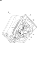
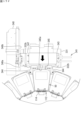
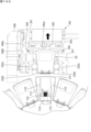
- FIG. 1 is a plan view showing an example of the overall configuration of a medicine packaging system according to an embodiment.
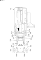
- FIG. 2 is a front view showing an example of the overall configuration of the medicine packaging system according to the embodiment.
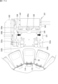
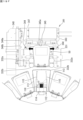
- FIG. 3 is a plan view illustrating an example of a configuration of a cassette housing portion according to the embodiment.
- FIG. 4 is a perspective view showing the bottom surface of the cassette according to the embodiment.
- FIG. 5 is a front view of the cassette according to the embodiment.
- FIG. 6 is a side view of the cassette according to the embodiment.
- FIG. 7 is a view taken along line AA in FIG.
- FIG. 8 is a view taken along line BB in FIG.
- FIG. 9 is a perspective view illustrating an example of the configuration of a transport head according to the embodiment.
- FIG. 10 is a front view illustrating an example of the configuration of a transport head according to an embodiment.
- FIG. 11 is a plan view illustrating an example of the configuration of the stand according to the embodiment.
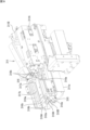
- FIG. 12 is a perspective view showing the positional relationship between the storage cylinder and the second transport unit.
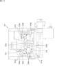
- FIG. 13 is a plan view illustrating an example of the configuration of a push-out mechanism according to an embodiment.
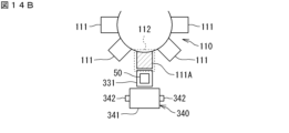
- FIG. 14A is a diagram illustrating an example of the transport of a cassette by the second transport unit.
- FIG. 14B is a diagram illustrating an example of the transport of the cassette by the second transport unit.
- FIG. 14C is a diagram showing an example of the transport of the cassette by the second transport unit.
- FIG. 15A is a plan view for explaining the first carry-in operation.
- FIG. FIG. 11 is a plan view illustrating an example of the configuration of the stand according to the embodiment.
- FIG. 12 is a perspective view showing the positional relationship between the storage cylinder and the second transport
- FIG. 15B is a side view for explaining the first loading operation.
- FIG. 15C is a plan view for explaining the first carry-in operation.
- FIG. 15D is a plan view for explaining the first carry-in operation.
- FIG. 15E is a plan view for explaining the first carry-in operation.
- FIG. 15F is a plan view for explaining the first carry-in operation.
- FIG. 15G is a side view for explaining the first loading operation.
- FIG. 15H is a plan view for explaining the first carry-in operation.
- FIG. 16A is a side view for explaining the first carrying-out operation.
- FIG. 16B is a plan view for explaining the first unloading operation.
- FIG. 16C is a plan view for explaining the first unloading operation.
- FIG. 16A is a side view for explaining the first carrying-out operation.
- FIG. 16B is a plan view for explaining the first unloading operation.
- FIG. 16C is a plan view for explaining the first unloading operation.
- FIG. 16D is a side view for explaining the first ejection operation.
- FIG. 16E is a plan view for explaining the first unloading operation.
- FIG. 16F is a plan view for explaining the first unloading operation.
- FIG. 16G is a plan view for explaining the first unloading operation.
- FIG. 16H is a plan view for explaining the first unloading operation.
- FIG. 17A is a plan view for explaining the second loading operation.
- FIG. 17B is a plan view for explaining the second loading operation.
- FIG. 17C is a plan view for explaining the second loading operation.
- FIG. 17D is a plan view for explaining the second loading operation.
- FIG. 17E is a plan view for explaining the second loading operation.
- FIG. 17F is a plan view for explaining the second loading operation.
- FIG. 17A is a plan view for explaining the second loading operation.
- FIG. 17B is a plan view for explaining the second loading operation.
- FIG. 17C is a plan view for
- FIG. 17G is a plan view for explaining the second loading operation.
- FIG. 17H is a plan view for explaining the second loading operation.
- FIG. 18A is a plan view for explaining the operation of the first roller and the second roller.
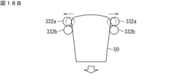
- FIG. 18B is a plan view for explaining the operation of the first roller and the second roller.
- FIG. 18C is a plan view for explaining the operation of the first roller and the second roller.
- FIG. 19A is a plan view for explaining the second unloading operation.
- FIG. FIG. 19B is a plan view for explaining the second unloading operation.
- FIG. 19C is a plan view for explaining the second unloading operation.
- FIG. 19D is a plan view for explaining the second unloading operation.
- FIG. 19E is a plan view for explaining the second unloading operation.
- FIG. 19F is a plan view for explaining the second unloading operation.
- FIG. 19G is a plan view for explaining the second unloading operation.
- FIG. 20 is
- the drug packaging system includes a first storage area for storing cassettes containing drugs and dispensing drugs from the stored cassettes, a second storage area for storing the cassettes to be transported to the first storage area, a first transport unit for transporting the cassettes within the second storage area, a second transport unit for transporting the cassettes from the second storage area to the first storage area, and a packaging unit for packaging the drugs dispensed from the cassettes stored in the first storage area in packages for each dosage unit.
- the second storage area may include a first storage position that stores the cassette that has been introduced into the drug packaging system from outside the drug packaging system, and a second storage position that stores the cassette that is to be transported to the first storage area, and the first transport unit may transport the cassette from the first storage position to the second storage position.
- This allows the cassette to be temporarily stored in the second storage position before being transported to the first storage area. While a cassette is stored in the second storage position, another cassette can be stored in the first storage position, and drugs can be dispensed from a cassette stored in the first storage area. Therefore, cassettes can be transported on a flexible schedule.
- the second storage position may be located between the first storage area and the first storage position. This allows the cassette to be efficiently transported from the first storage position to the first storage area via the second storage position located between the first storage position and the first storage area.
- the first storage areas may be arranged in a first direction, and the first storage position may be located in a second direction intersecting the first direction from the first storage areas. This makes it possible to reduce variation in the distance of the first storage position from each of the first storage areas, and to efficiently transport the cassette from the first storage position to the first storage area.
- a plurality of the second storage positions may be provided corresponding to the plurality of first storage areas. This allows the cassettes to be transported to each of the first storage areas to be temporarily stored in each of the second storage positions.
- the second transport unit may push the cassette from the second storage area to the first storage area. This makes it possible to prevent the configuration of the second transport unit from becoming complicated.
- the first storage area may be a cylindrical storage cylinder that can rotate in a circumferential direction. This allows the cassettes stored in the first storage area to be moved by rotating the storage cylinder, making it possible to transport the cassettes more efficiently.
- the storage cylinder may include a plurality of cassette storage sections capable of storing cassettes, the plurality of cassette storage sections may be arranged in a circumferential direction of the storage cylinder, and the second transport section may transport the cassette from the second storage area to one of the plurality of cassette storage sections. This allows many cassettes to be stored in the first storage area of limited size, and also prevents the configuration of the second transport section from becoming complicated.
- the multiple cassette storage sections can sequentially pass through specific loading positions, and the second transport section may load the cassette into the cassette storage section located at the loading position by transporting the cassette from the second storage area to the loading position. This allows the second transport section to transport the cassette to any cassette storage section of the storage cylinder.
- the drug packaging system may include a third storage area for storing cassettes containing drugs and dispensing the drugs from the stored cassettes, and a plurality of the storage cylinders may be arranged in a first direction, and the third storage area may be located in a space formed by two adjacent storage cylinders. This allows the plurality of storage cylinders and the second storage area to be efficiently arranged, and the entire drug packaging system to be made smaller.
- the drug packaging system may include a supply unit that supplies the drug dispensed from the cassette stored in the first storage area and the drug dispensed from the cassette stored in the third storage area to the packaging unit. This allows various combinations of drugs to be packaged together.
- the cassette stored in the first storage area may be a first cassette containing the same type of medicine
- the cassette stored in the third storage area may be a second cassette that can select the medicine to be contained from multiple types of medicine.
- the pharmaceutical packaging system may include a third conveying unit that conveys a second cassette to the third storage area by a second conveying path different from the first conveying path of the first cassette by the first conveying unit. This allows the first cassette and the second cassette to be individually conveyed by different paths.
- the first storage area may be located between the first transport path and the second transport path, the second storage area may be adjacent to a first portion of the first storage area that is close to the first transport path, and the third storage area may be adjacent to a second portion of the first storage area that is close to the second transport path. This allows each of the first cassette and the second cassette to be transported via an efficient route.
- the drug packaging system may include a housing that houses the first storage area, the second storage area, and the third storage area, the housing including a first surface, a second surface, and a third surface, the first surface and the second surface being two surfaces opposite each other, the third surface connecting the first surface and the second surface, the first transport path being closer to the first surface than the first storage area, the second transport path being closer to the second surface than the first storage area, and the third surface including a first transfer port for receiving the first cassette transported by the first transport path and a second transfer port for receiving the second cassette transported by the second transport path.
- the drug packaging system includes a cylindrical storage cylinder that can rotate in a circumferential direction for storing multiple cassettes containing drugs and dispensing drugs from the stored cassettes, a storage area adjacent to the storage cylinder and capable of storing multiple cassettes, a transport unit that transports the cassettes between the storage cylinder and the storage area, and a packaging unit that packages drugs dispensed from the cassettes stored in the storage cylinder in packaging material.
- a cylindrical storage cylinder that can rotate in a circumferential direction for storing multiple cassettes containing drugs and dispensing drugs from the stored cassettes
- a storage area adjacent to the storage cylinder and capable of storing multiple cassettes a transport unit that transports the cassettes between the storage cylinder and the storage area
- a packaging unit that packages drugs dispensed from the cassettes stored in the storage cylinder in packaging material.
- FIG. 1 is a plan view showing an example of the overall configuration of a medicine packaging system according to an embodiment
- FIG. 2 is a front view thereof.
- the drug packaging system 10 includes a packaging device 100, a winding device 200, a cassette storage device 300, a cassette distribution device 400, and an operating device 500.
- the packaging device 100 dispenses medicine from cassettes 50, 60 that contain the medicine, and packages the dispensed medicine in a package.
- the winding device 200 winds up a continuous packaging band of multiple packages in which medicine is packaged by the packaging device 100.
- the packaging device 100 can store multiple cassettes 50 and dispense medicines from the stored cassettes 50.
- a single cassette 50 contains the same type of medicine.
- the cassette 50 is a cassette dedicated to a specific type of medicine.
- the cassette 50 is an example of a "first cassette.”
- the packaging device 100 stores multiple cassettes 50, each corresponding to a different type of medicine.
- the packaging device 100 can store multiple cassettes 60 and dispense medicines from the stored cassettes 60.
- a single cassette 60 contains a drug selected from multiple types of drugs other than the drug contained in cassette 50.
- cassette 60 is a cassette that can accommodate multiple types of drugs.
- cassette 60 is capable of adjusting the size of the drug discharge path. By adjusting the size of the discharge path according to the size of the drug selected from multiple types of drugs, cassette 60 becomes able to dispense this drug.
- Cassette 60 is an example of a "second cassette.” For example, a drug that is used frequently is contained in cassette 50, and a drug that is used less frequently is contained in cassette 60.
- the multiple packaging devices 100 and the multiple winding devices 200 are arranged in a row.
- the winding devices 200 correspond one-to-one to the packaging devices 100.
- the packaging devices 100 and the corresponding winding devices 200 are arranged next to each other. In other words, the packaging devices 100 and the winding devices 200 are arranged alternately in a row.
- a drug packaging system 10 is shown that includes three packaging devices 100 and three winding devices 200.
- the number of packaging devices 100 and winding devices 200 is not limited to three.
- the drug packaging system 10 may include one packaging device 100 and one winding device 200, two packaging devices 100, or four or more packaging devices 100 and winding devices 200.
- the direction in which the packaging device 100 and the winding device 200 are lined up will be referred to as the "left-right direction” or “lateral direction.”
- the horizontal direction perpendicular to the left-right direction will be referred to as the “front-back direction.”
- the "left-right direction,” “front-back direction,” and “up-down direction” used below are directions common to the entire pharmaceutical packaging system 10, and are not individual directions for each unit.
- the cassette storage device 300 is disposed behind the packaging device 100 and the winding device 200.
- the cassette storage device 300 can store multiple cassettes 50.
- the filling station 450 is located to the left of the leftmost packaging device 100.
- the filling station 450 includes a cassette distribution device 400 and an operating device 500.
- the operating device 500 is used by an operator to operate the drug packaging system 10.
- the operating device 500 is disposed on the leftmost side of the drug packaging system 10.
- the operating device 500 includes an input device 510 for the operator to input drug information.
- the input device 510 includes, for example, a barcode reader, an RFID (Radio Frequency Identification) reader, and a display.
- a barcode reader for example, a drug container containing a drug is supplied from a pharmaceutical company.
- the drug container is provided with a barcode that records information about the drug contained therein.
- the operator reads the barcode of the drug container using a barcode reader. This allows information about the drug (including the drug ID) to be input to the operating device 500.
- An RF tag is attached to the cassette 50, and a cassette number for identifying the cassette 50 and the drug ID of the drug to be contained in the cassette are recorded on this RF tag.
- the operator reads the RF tag of the cassette 50 using an RFID reader. The read drug ID and cassette number are shown on the display, allowing the operator to match the cassette number with the drug ID.
- the operating device 500 includes a first transfer opening 520 for receiving the cassette 50.
- the first transfer opening 520 allows the cassette 50 to be placed therein, and opens on the left side of the operating device 500.
- the first transfer opening 520 has a door, and at the back of the door there is a platform for placing the cassette 50. The operator can place a new cassette 50 in the first transfer opening 520.
- the operating device 500 includes a second transfer port 530 for receiving the cassette 60.
- the second transfer port 530 is capable of placing the cassette 60 and opens on the left side of the operating device 500.
- the second transfer port 530 has a door and has a platform behind the door for placing the cassette 60. The operator can place a new cassette 60 in the second transfer port 530.
- the housing 11 includes a panel-shaped front surface 11a, a rear surface 11b, a left side surface 11c, and a right side surface 11d.
- the front surface 11a constitutes the front surface of the packing device 100 and the winding device 200.
- the rear surface 11b constitutes the rear surface of the cassette storage device 300.
- the left side surface 11c constitutes the left side surface of the operating device 500 (hereinafter also referred to as the "operation surface") and the left side surface of the cassette storage device 300.
- the right side surface 11d constitutes the right side surface of the rightmost winding device 200 and the right side surface of the cassette storage device 300. Note that part of the front surface 11a is omitted in FIG. 2.
- the first and second transfer ports 520 and 530 open on the operation surface 11c.
- the input device 510 is also provided on the operation surface 11c. This allows the operator to concentrate on the operation surface 11c while operating the drug packaging system 10.
- the cassette distribution device 400 can transport the cassette 50 between the first transfer opening 520 and the first cassette transfer position 410.
- the first cassette transfer position 410 faces the cassette storage device 300.
- the first cassette transfer position 410 is a position for transferring the cassette 50 between the cassette distribution device 400 and the cassette storage device 300.
- the cassette storage device 300 includes a first transport section 310.
- the first transport section 310 transports the cassette 50 inside the cassette storage device 300.
- the cassette storage device 300 transports and stores the cassette 50 received at the first cassette transfer position 410 by the first transport section 310.
- the cassette storage device 300 is an example of a "second storage area.”
- the cassette storage device 300 includes storage shelves 320, 350 and a cassette table 330.
- the storage shelves 320, 350 can store multiple cassettes 50.
- Each of the multiple cassette tables 330 is adjacent to the packing device 100 at the rear of the packing device 100.
- the cassette tables 330 are provided corresponding to each of the storage cylinders 110 described below.
- the cassette table 330 stores the cassettes 50 to be transported to the packing device 100.
- the cassette table 330 is a preparation area for preparing the transport of the cassettes 50 to the packing device 100.
- the storage shelf 320 is an example of a "first storage position"
- the cassette table 330 is an example of a "second storage position”.
- the storage shelf 320 may not only be provided behind the cassette table 330, but may also be added in substantially the same vertical plane as the cassette table 330 (i.e., lined up in the left-right direction with the cassette table 330). This allows the capacity of the cassette 50 to be increased.
- multiple cassette tables 330 are arranged in a row at regular intervals in the left-right direction.
- the multiple storage shelves 350 are arranged on the left and right of the cassette table 330 at the rear of the packaging device 100. That is, the storage shelves 350 are arranged between adjacent cassette tables 330 in the left-right direction. In other words, the cassette table 330 is arranged between two storage shelves 350. For example, in one cassette table 330, the left storage shelf 350 corresponds to the "first storage” and the right storage shelf 350 corresponds to the "second storage.”
- Storage shelf 320 is positioned at a certain distance behind cassette table 330 and storage shelf 350. Storage shelf 320 corresponds to the "third storage cabinet.”
- the first transport section 310 transports the cassettes 50 between the storage shelf 320 and the cassette table 330 and storage shelf 350. That is, a transport space is provided behind the cassette table 330 and storage shelf 350 for the first transport section 310 to transport the cassettes 50.
- the storage shelf 320 is disposed behind the transport space.
- the cassette storage device 300 further includes a second conveying section 340.
- the second conveying section 340 conveys the cassette 50 from the cassette table 330 to the packaging device 100.
- the cassette 50 conveyed from the cassette table 330 to the packaging device 100 is stored within the packaging device 100.
- the cassette tables 330 are provided in six locations, each corresponding to a storage cylinder 110 described below.
- a conveying device 600 is disposed in front of the multiple packaging devices 100.
- the conveying device 600 is capable of conveying the cassettes 60.
- the conveying device 600 is an example of a "third conveying section.”
- the cassette distribution device 400 can transport the cassette 60 between the second transfer opening 530 and the second cassette transfer position 420.
- the second cassette transfer position 420 faces the left end portion of the transport device 600.
- the second cassette transfer position 420 is a position for transferring the cassette 60 between the cassette distribution device 400 and the transport device 600.
- the conveying device 600 conveys the cassette 60 received at the second cassette transfer position 420 to one of the multiple packaging devices 100.
- the conveying device 600 is an example of a "third conveying section.”
- the cassette 60 conveyed by the conveying device 600 is stored in the packaging device 100.
- the packaging device 100 includes a storage cylinder 110 capable of storing a plurality of cassettes 50 each containing medicines (tablets) for each medicine type.
- the storage cylinder 110 is cylindrical and configured to be rotatable in the circumferential direction.
- the storage cylinder 110 is a storage area for storing the cassette 50.
- the storage cylinder 110 is capable of dispensing medicines from the stored cassette 50.
- the storage cylinder 110 is an example of a "first storage area.”
- the storage cylinder 110 includes a plurality of cassette accommodating sections 111 capable of accommodating cassettes 50.
- the plurality of cassette accommodating sections 111 are arranged in the circumferential direction and the vertical direction of the storage cylinder 110.
- One cassette 50 is accommodated (held) in one cassette accommodating section 111.
- the central cylinder of the storage cylinder 110 is hollow, and the internal space serves as a passageway for the medicine.
- the cassette accommodating section 111 is provided with a chute through which the medicine dispensed from the cassette 50 passes, and the chute of each cassette accommodating section 111 is connected to the internal space of the storage cylinder 110. The medicine dispensed from the cassette 50 passes through the chute and the internal space and falls below the packaging device 100.
- two storage cylinders 110 are provided in one packaging device 100.
- the two storage cylinders 110 are lined up in the left-right direction within the packaging device 100.
- the number of storage cylinders 110 included in the packaging device 100 is not limited to two.
- the packaging device 100 may be provided with one storage cylinder 110, or may be provided with three or more storage cylinders 110.
- the packaging device 100 is provided with multiple storage cylinders 110, the multiple storage cylinders 110 are lined up in a row in the left-right direction.
- the left-right direction is an example of the "first direction".
- FIG. 3 is a plan view showing an example of the configuration of the cassette storage section according to the embodiment.
- the cassette storage sections 111 are arranged in a circular ring shape.
- a set of the cassette storage sections 111 arranged in a circular ring shape are arranged in a plurality of stages in the vertical direction.
- the cassette storage sections 111 are arranged on one plane. That is, in the storage cylinder 110, the cassette storage sections 111 are arranged in a circular ring shape on each of a plurality of planes arranged in the vertical direction.
- the storage cylinder 110 can rotate around the central axis of the ring.
- the set of the cassette storage sections 111 in each stage can move in a circular ring shape on the corresponding plane.
- the set of the cassette storage sections 111 arranged in a circular ring shape corresponds to a "cassette holding section.”
- Each cassette storage section 111 is configured in a flat platform shape, and the cassette 50 can be placed on the upper surface.
- the cassette storage section 111 includes a table 113 that is fan-shaped with a missing tip when viewed from above, and a holding section 114 for holding the cassette 50 placed on the table 113.
- the table 113 is a platform on which the cassette 50 is placed.
- the holding section 114 is provided on the tip side of the fan shape of the table 113.
- the holding section 114 is provided with an inlet 114a through which the medicine dispensed from the cassette 50 is inserted.
- the inlet 114a is connected to a chute 114b.
- the cassette storage section 111 includes a locking section 115 for locking the retention of the cassette 50.
- the locking section 115 is two arms that extend radially outward from the retention section 114 in a sector shape.
- a protrusion 115a is provided at the longitudinal middle of each of the two locking sections 115.
- the protrusion 115a of the right locking section 115 protrudes to the right, and the protrusion 115a of the left locking section 115 protrudes to the left.
- FIG. 4 is a perspective view showing the bottom surface of a cassette according to an embodiment.
- An outlet 57 for discharging the medicine is opened in the bottom surface 51 of the cassette 50.
- a pair of engagement portions 55 that engage with the lock portion 115 of the cassette storage portion 111 are provided on the bottom surface of the cassette 50.
- the engagement portions 55 are biased in a direction toward each other by a spring (not shown), and can move in a direction away from each other.
- the pair of locking sections 115 come into contact with the pair of engaging sections 55. More specifically, the left side of the right engaging section comes into contact with the right side surface of the right locking section 115, and the right side of the left engaging section comes into contact with the left side surface of the left locking section 115.
- the engaging section 55 comes into contact with the protrusion 115a. The two engaging sections 55 move away from each other along the protrusion 115a, and when they pass the protrusion 115a, they return to their original positions due to the biasing force. This causes the locking sections 115 and the engaging sections 55 to engage, locking the cassette 50 in place.
- a gear 56 is provided on the bottom side of cassette 50.
- gear 56 meshes with gear 116 provided on holding portion 114.
- gear 116 is driven by a motor (not shown)
- gear 56 rotates, and a drug dispensing mechanism (not shown) built into cassette 50 operates.
- the drug dispensing mechanism dispenses a predetermined number of drugs from outlet 57, and the dispensed drugs are fed into inlet 114a.
- FIG. 5 is a front view of a cassette according to an embodiment (viewed from the outside of the sector), and FIG. 6 is a side view thereof.
- recesses 53 are formed in the vertical middle portion in the range from the radial middle position to the outer edge. In other words, the radial outer portion of the cassette 50 has a reduced width in the vertical middle portion. The recesses 53 are used as a point for the user to grip the cassette 50.
- the lower bottom of the recess 53 of the cassette 50 protrudes from both sides of the cassette 50. More specifically, below the recess 53 described above, a protrusion 52 is provided that protrudes to the side.
- the outer edge shape of the pair of protrusions 52 corresponds to the outer edge shape of the portion of the cassette 50 above the recess 53. In other words, the outer edge of the protrusion 52 forms part of a sector with a missing tip in a plan view.
- the upper surface of the protrusion 52 is an inclined surface 52a that slopes downward toward the outside. Because the protrusion 52 forms part of a sector with its tip missing in a plan view, the outer edge shape of the inclined surface 52a slopes downward toward the outside when viewed from the front, that is, when viewed in the radial direction of the sector toward the center (angle ⁇ in FIG. 5). In other words, the outer edge of the inclined surface 52a in a front view includes a straight line that intersects with a straight line extending along the bottom surface of the cassette 50 at an angle ⁇ .
- a button 54 for unlocking the locking portion 115 is disposed in the recess 53.
- the button 54 works in conjunction with the engagement portions 55.
- the pair of engagement portions 55 move in directions away from each other. This releases the engagement (lock) between the locking portion 115 and the engagement portions 55.
- each of the packaging devices 100 includes a cassette storage unit 120.
- the cassette storage unit 120 is a storage area that stores a plurality of cassettes 60.
- the cassette storage unit 120 can dispense medicines from the stored cassettes 60.
- the cassette storage unit 120 is an example of a "third storage area.”
- the cassette storage unit 120 includes a plurality of cassette storage sections 121 capable of storing cassettes 60.
- the plurality of cassette storage sections 121 are arranged in the vertical direction.
- One cassette 60 is stored in one cassette storage section 121.
- the cassette storage unit 120 is located in the space formed by two adjacent storage cylinders 110. Specifically, two spaces that are essentially triangular in plan view are formed between two adjacent cylindrical storage cylinders 110. The cassette storage unit 120 is disposed in the front space of the two triangular spaces. This increases the storage capacity of the cassettes 50, 60 in the packaging device 100 and enables the packaging device 100 to be made more compact.
- the packaging device 100 further includes a manual distribution unit 130.
- the manual distribution unit 130 is also referred to as a DTA (Detachable Tablet Adapter).
- the manual distribution unit 130 is used to dispense tablets that are not suitable for dispensing from the cassettes 50 and 60, such as half tablets or 1 ⁇ 4 tablets that are less than one tablet.
- the manual distribution unit 130 is provided below the storage cylinder 110 and the cassette storage unit 120.
- the manual distribution unit 130 is a drawer-like box body, and inside it, multiple compartments capable of containing medicines are arranged in a lattice pattern. When using the manual distribution unit 130, the operator pulls out the manual distribution unit 130, places medicines in the compartments, and then returns the manual distribution unit 130.
- the packaging device 100 further includes a supply section 140 and a packaging section 150.
- the supply unit 140 supplies the medicine dispensed from the cassette 50 stored in the storage cylinder 110, the medicine dispensed from the cassette 60 stored in the cassette storage unit 120, and the medicine dispensed from the manual distribution unit 130 to the packaging unit 150.
- the supply unit 140 includes a hopper 141 and a hopper 142.
- the hoppers 141 and 142 are in an inverted cone shape, an inverted triangular pyramid shape, an inverted square pyramid shape, etc.
- the hopper 141 supplies the medicine dispensed from the cassette 50 stored in the storage cylinder 110, and the medicine dispensed from the cassette 60 stored in the cassette storage unit 120 to the packaging unit 150.
- the hopper 142 supplies the medicine dispensed from the manual distribution unit 130 to the packaging unit 150.
- the packaging unit 150 packages the medicine supplied from the supply unit 140 in a package 71.
- the packaging band 70 is composed of multiple packages 71 arranged in a continuous band shape.
- the packages 71 are bag-shaped and contain the medicine.
- the packaging unit 150 rotatably holds a roll 73 of the sheet 72 before the packaging band 70 is formed.
- the packaging unit 150 pulls out the sheet 72 from the roll 73 and forms a bag-shaped pocket by gluing (heat sealing) the folded sheet 72 over the entire width at a portion of the longitudinal direction.
- the medicine is dropped into the pocket below the supply unit 140.
- the entire width and a portion of the longitudinal direction of the sheet 72 (the edge opposite the fold) are then glued, and the two open sides of the pocket are sealed to form a rectangular package 71.
- the packaging unit 150 has a function for inspecting medicine before it is packaged.
- the packaging unit 150 includes a camera (not shown) that captures an image of the medicine before it is dropped into a pocket. The image captured by the camera is analyzed to inspect whether the desired medicine has been packaged.
- the winding device 200 winds up the wrapping strip 70 coming from the packaging section 150 into a roll.
- the wrapping strip 70 wound up by the winding device 200 is collected by an operator.
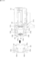
- FIG. 7 is a view taken along line AA in FIG.
- the storage shelf 320 includes a plurality of shelves 321 arranged vertically. Each shelf 321 has a plurality of storage sections 322 arranged horizontally at regular intervals. One storage section 322 can store one cassette 50. That is, the storage shelf 320 has a plurality of storage sections 322 arranged in rows and columns.
- the first transport unit 310 is disposed in front of the storage shelf 320 (see FIG. 1).
- the first transport unit 310 includes a transport head 311, a lifting unit 312, and a horizontal drive unit 313.
- the transport head 311 can hold the cassette 50 by a holding mechanism.
- the lifting unit 312 includes a rail 314 extending in the vertical direction and a motor, and moves the transport head 311 in the vertical direction along the rail 314.
- the horizontal drive unit 313 includes a rail 315 extending in the left-right direction and a motor, and moves the transport head 311 and the lifting unit 312 in the left-right direction along the rail 315. That is, the transport head 311 can move in the vertical direction and the left-right direction in front of the storage shelf 320.
- the transport head 311 is configured to be rotatable 180 degrees horizontally by a motor.
- the transport head 311 can rotate between facing forward and facing backward.
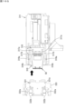
- FIG. 8 is an arrow view taken along line B-B in FIG. 1.
- the first conveying section 310 is disposed behind the cassette distribution device 400, the packaging device 100, the winding device 200, and the storage cabinet 350. In other words, the first conveying section 310 is disposed between the packaging device 100 and the storage shelf 320, or in other words, between the storage cabinets 350 and 320.
- storage shelf 350 includes multiple shelves 321 arranged in the vertical direction. Each shelf 321 has multiple storage sections 322 arranged in the horizontal direction at regular intervals. In storage shelf 350, multiple storage sections 322 are arranged in rows and columns.
- the first transport section 310 moves the transport head 311 up and down, left and right, or both, to a position facing the first cassette transfer position 410.
- the transport head 311 holds the cassette 50 located at the first cassette transfer position 410, and pulls the cassette 50 rearward from the first cassette transfer position 410. This enables the first transport section 310 to receive the cassette 50 from the cassette distribution device 400.
- Figure 9 is a perspective view showing an example of the configuration of the transport head 311 according to an embodiment
- Figure 10 is a front view thereof.
- the transport head 311 includes a base portion 311a, a contact portion 316, and a support portion 318.
- the base portion 311a is equipped with a contact portion 316 and a support portion 318.
- the contact portion 316 can move in the longitudinal direction.
- the transport head 311 takes in or out the cassette 50 from the storage 320
- the transport head 311 faces in a direction facing the storage 320, i.e., toward the rear.
- the contact portion 316 can move backward and forward.
- the transport head 311 takes in or out the cassette 50 from the storage 350 or the cassette table 330
- the transport head 311 faces in a direction facing the storage 320 or the cassette table 330, i.e., toward the front.
- the contact portion 316 can move forward and backward.
- the following description will be given of the state in which the transport head 311 faces forward.
- the contact portion 316 is used to come into contact with the cassette 50 and hold the cassette 50.
- the contact portion 316 includes a protrusion 316a that protrudes upward and two holding plates 316b.
- the protrusion 316a is located at the tip of the contact portion 316, and the holding plates 316b are located behind the protrusion 316a.
- a recess 51a is provided on the bottom surface 51 of the cassette 50.
- the recess 51a is provided on the front side of the cassette 50, that is, on the outermost part of the sector.
- the protrusion 316a can be inserted into the recess 51a.
- the holding plate 316b comes into contact with the front surface of the cassette 50, or is located at a small distance behind the cassette 50. If the cassette 50 is lifted only by the contact portion 316 with the protrusion 316a inserted into the recess 51a, there is nothing to support the bottom surface of the cassette 50, and the rear side of the cassette 50 (i.e., the tip side of the sector) drops. At this time, the holding plate 316b comes into contact with the front surface of the cassette 50. Therefore, the cassette 50 is held by the protrusion 316a and the holding plate 316b, and does not fall off the conveying head 311.
- the contact portion 316 has linear guide carriages 317a at both the left and right ends.
- the support portion 318 is provided with a pair of rails 317b, and each carriage 317a engages with the rails 317b and can move in the front-rear direction along the rails 317b. This allows the contact portion 316 to move in the front-rear direction relative to the support portion 318.
- the base portion 311a is provided with a motor 311A for moving the contact portion 316.
- the power of the motor 311A is transmitted to the contact portion 316, and the contact portion 316 moves linearly along the rail 317b.
- the support portion 318 is disposed below the contact portion 316.
- the support portion 318 can move forward and backward.
- the support part 318 has guide parts 319a including linear guide carriages on both the left and right ends.
- a pair of rails 319b is provided on the base part 311a, and the carriages provided on each guide part 319a engage with the rails 319b and can move in the front-rear direction along the rails 319b. This allows the support part 318 to move in the front-rear direction relative to the base part 311a. In other words, the contact part 316 and the support part 318 can move in the front-rear direction independently of each other.
- the guide portions 319a are spaced apart from each other in the left-right direction. Each guide portion 319a extends in the front-rear direction.
- the two guide portions 319a have a cutout on the underside of the opposing surface. That is, one corner of the rectangular bar of the guide portion 319a is missing along the entire longitudinal direction, and the pressing surface 319A, which is an inclined surface, extends in the longitudinal direction.
- the inclination angle of the pressing surface 319A is the same angle ⁇ as the angle ⁇ of the protrusion 52 of the cassette 50 when viewed from the front (see FIG. 5).
- the base portion 311a is provided with a motor 311B for moving the support portion 318.
- the power of the motor 311B is transmitted to the support portion 318, and the support portion 318 moves linearly along the rail 319b.
- the support portion 318 has a pair of first rollers 318a and a pair of second rollers 318b at its tip.
- the pair of first rollers 318a are attached to a shaft 318A extending in the left-right direction so as to be aligned in the left-right direction. Each first roller 318a can rotate around the shaft 318A.
- a shaft 318B extending in the left-right direction is arranged behind the shaft 318A.
- the pair of second rollers 318b are attached to the shaft 318B so as to be aligned in the left-right direction. Each second roller 318b can rotate around the shaft 318B.
- the shafts 318A and 318B are arranged at the same height, and the first rollers 318a and the second rollers 318b have the same radius.
- the first roller 318a and the second roller 318b are used to support the cassette 50.
- the protrusion 316a is inserted into the recess 51a of the cassette 50 and the first roller 318a and the second roller 318b are located forward of the protrusion 316a, the bottom surface of the cassette 50 comes into contact with the upper end points of the first roller 318a and the second roller 318b.
- the contact portion 316 moves relative to the support portion 318 in the front-to-rear direction
- the cassette 50 moves on the first roller 318a and the second roller 318b, and the first roller 318a and the second roller 318b rotate as the cassette 50 moves.
- the pair of guide portions 319a are spaced apart by a distance corresponding to the maximum width of the cassette 50, specifically, a distance slightly greater than the maximum width of the cassette 50. Therefore, the cassette 50 can move back and forth between the guide portions 319a on the support portion 318. Furthermore, as described above, the guide portion 319a is provided with a pressing surface 319A. Since the angle ⁇ of the pressing surface 319A corresponds to the angle ⁇ of the bottom of the cassette 50, the guide portion 319a engages with the recess 53 of the cassette 50, and the pressing surface 319a is positioned above the protrusion 52 of the cassette 50. Therefore, when the cassette 50 moves on the support portion 318, the upward movement of the cassette 50 is suppressed, and the cassette 50 is prevented from falling off the support portion 318.
- the first transport unit 310 rotates the transport head 311 holding the cassette 50 to face it to the right or left.
- the first transport unit 310 moves the transport head 311 in this state in the vertical and horizontal directions, or both.
- the first transport unit 310 positions the transport head 311 in front of one of the empty storage sections 322 of the storage shelf 320, and rotates the transport head 311 horizontally (forward and backward) to face it backward (toward the rear surface 11b).
- the transport head 311 moves the cassette 50 it is holding backward, so that the cassette 50 is stored in the storage section 322.
- the transport head 311 releases the cassette 50, completing the movement of the cassette 50 to the storage shelf 320.
- the first transport unit 310 rotates the transport head 311 that has released the cassette 50, and faces it to the right or left. In this state, the first transport unit 310 can move the transport head 311 in the vertical and horizontal directions.
- the first transport unit 310 can take out a cassette 50 from one storage unit 322 and transport the cassette 50 to a storage unit 322 that is in a different row, column, or both from the first storage unit 322. That is, the first transport unit 310 moves the transport head 311 to a position facing one storage unit 322, and rotates the transport head 311 horizontally to face backward. The transport head 311 holds the cassette 50 stored in the storage unit 322 and pulls it out forward from the storage unit 322.
- the first transport unit 310 rotates the transport head 311 holding the cassette 50 to face it to the right or left.
- the first transport unit 310 moves the transport head 311 in this state up and down, left and right, or both.
- the first transport unit 310 positions the transport head 311 in front of the target storage unit 322 (in the direction approaching the front surface 11a), and rotates the transport head 311 horizontally to face it backwards.
- the transport head 311 moves the cassette 50 it is holding to the rear, whereby the cassette 50 is stored in the storage unit 322.
- the transport head 311 releases the cassette 50, completing the movement of the cassette 50 within the storage shelf 320.
- the cassette table 330 includes a number of stands 331.
- the stand 331 is a plate-like member capable of supporting one cassette 50.
- the same number of stands 331 as the number of stages in the storage cylinder 110 are lined up in the vertical direction.
- Each stand 331 corresponds to one stage of the storage cylinder 110.
- the stands 331 are positioned at the same height as the corresponding stage of the storage cylinder 110.
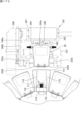
- FIG. 11 is a plan view showing an example of the configuration of a stand 331 according to an embodiment.
- the stand 331 includes a flat body portion 331a and a base portion 333.
- the body portion 331a is disposed on the base portion 333 and is supported by the base portion 333.
- the main body 331a has a T-shape in a plan view. That is, the main body 331a includes a first portion 334a that corresponds to the wide part of the T, and a second portion 334b that corresponds to the narrow part of the T. In the main body 331a, the first portion 334a is located at the rear, and the second portion 334b is located at the front.
- the width (left-right length) of the first portion 334a is greater than the width of the cassette 50.
- the width of the second portion 334b is smaller than the width of the cassette 50.
- a pair of first rollers 332a and a pair of second rollers 332b are arranged on both sides of the second portion 334b. Each of the first rollers 332a and the second rollers 332b is attached to the base portion 333. The first rollers 332a are arranged rearward of the second rollers 332b.
- the pair of first rollers 332a are biased by a spring in a direction in which they approach each other (left-right direction). That is, the pair of first rollers 332a can move in a direction in which they move away from each other. In a natural state in which the pair of first rollers 332a are closest to each other, they are separated from each other by a distance that is greater than the width of the narrowest part of the cassette 50 (the part closest to the center of the sector in the radial direction), which is a sector with a missing tip in a plan view, and smaller than the width of the widest part of the cassette 50 (the part farthest from the center of the sector in the radial direction).
- the distance between the pair of first rollers 332a at this time is the distance between the closest points of the two first rollers 332a.
- the pair of first rollers 332a can move away from each other by a distance equal to or greater than the width of the widest part of the cassette 50.
- the pair of second rollers 332b are biased by a spring in a direction in which they approach each other (left-right direction). That is, the pair of second rollers 332b can move in a direction away from each other.
- the pair of second rollers 332b are in their natural state in which they are closest to each other, they are separated from each other by a distance that is greater than the width of the narrowest part of the cassette 50, which is a sector with a missing tip in a plan view, and smaller than the width of the widest part of the cassette 50.
- the distance between the pair of second rollers 332b at this time is the distance between the closest points of the two second rollers 332b.
- the pair of second rollers 332b can move away from each other by a distance equal to or greater than the width of the widest part of the cassette 50.
- the distance between the pair of second rollers 332b in the natural state is greater than the distance between the pair of first rollers 332a in the natural state.
- the cassette 50 slides from the front end of the main body 331a to the table 113.
- the cassette 50 comes into contact with the first roller 332a and the second roller 332b.
- the first roller 332a and the second roller 332b come into contact with both side surfaces of the cassette 50, and while the cassette 50 passes through the first roller 332a and the second roller 332b, the pair of first rollers 332a move away from each other due to the width of the cassette 50, and the pair of second rollers 332b move away from each other.
- This allows the cassette 50 to be transported without tilting horizontally, and the central axis of the cassette 50 in the left-right direction is aligned with the central axis of the table 113 in the left-right direction.
- the second conveying section 340 corresponds one-to-one to the cassette table 330.
- the second conveying section 340 is disposed behind the corresponding cassette table 330.
- Figure 12 is a perspective view showing the positional relationship between the storage cylinder 110 and the second conveying section 340.
- the second transport section 340 includes a push-out mechanism 341 and a rail 342.
- the rail 342 extends in the vertical direction at a position behind the corresponding cassette table 330.
- the push-out mechanism 341 has a built-in motor and can move in the vertical direction along the rail 342.
- the push-out mechanism 341 moves upward or downward to position itself behind the stand 331 in which the cassette 50 is placed. In this state, the push-out mechanism 341 moves the cassette 50 forward, thereby transporting the cassette 50 from the stand 331 to the cassette storage section 111.
- Figure 13 is a plan view showing an example of the configuration of the push-out mechanism 341 according to an embodiment.
- the pushing mechanism 341 includes a pushing member 347 and a base portion 348.
- the pushing member 347 is attached to the base portion 348 so as to be movable in the front-rear direction.
- the pushing member 347 has a linear guide carriage 346a at its left end.
- the base portion 348 is provided with a rail 346b, and the carriage 346a engages with the rail 346b and is movable in the front-rear direction along the rail 346b. This allows the pushing member 347 to move in the front-rear direction relative to the base portion 348.
- a motor is provided on the base portion 348 to move the push-out member 347 in the forward and backward directions.
- the power of the motor is transmitted to the push-out member 347, and the push-out member 347 moves in the forward and backward directions along the rail 346b.
- a catcher 344 consisting of a pair of claws is provided on the front surface of the push-out member 341.
- the pair of claws of the catcher 344 are arranged at a distance from each other in the left-right direction on the front surface of the push-out member 341.
- the pair of claws can move in the left-right direction so as to move closer to or away from each other.
- a motor (not shown) is mounted on the push-out member 341, and the power of the motor moves the claws so as to move closer to or away from each other.
- the catcher 344 is used to hold the cassette 50. That is, the catcher 344 holds the cassette 50 by pinching the recesses 53 on both sides of the cassette 50 from both sides.
- the catcher 344 is also used to press the button 54 provided in the recess 53 of the cassette 50. That is, when the pair of claws come close to each other, the claws come into contact with the button 54, and the button 54 is pressed in.
- a contact portion 345 is provided on the front surface of the push-out member 341 between a pair of claw portions of the catcher 355.
- the contact portion 345 protrudes forward from the front surface of the push-out member 341, and has a contact surface 345a, which is a flat surface facing forward, at its tip.
- the contact surface 345a is used to push out the cassette 50. That is, when the pair of claw portions are separated in the left-right direction and the hold of the cassette 50 by the catcher 344 is released, the push-out member 341 moves forward, causing the contact surface 345a to come into contact with the rear surface of the cassette 50. When the push-out member 341 moves further forward, the cassette 50 is pushed forward.
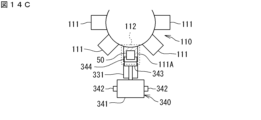
- Figures 14A to 14C show an example of the transport of the cassette 50 by the second transport unit 340.
- the loading position 112 is a position for loading and unloading the cassette 50 into the cassette storage section 111.
- the second transport section 340 can transport the cassette 50 to the cassette storage section 111 positioned at the loading position 112, and can unload the cassette 50 from the cassette storage section 111 positioned at the loading position 112.
- the storage cylinder 110 can be rotated clockwise or counterclockwise by a motor.
- the cassette storage section 111 that is intended to store the cassette 50 is indicated by diagonal lines as cassette storage section 111A.
- the cassette storage section 111A is positioned at the loading position 112 (FIG. 14B).
- the push-out mechanism 341 moves upward or downward and is positioned at the stage where the cassette storage section 111A is provided.
- the push-out mechanism 341 includes a push-out member 343 (FIG. 14C).
- the push-out mechanism 341 can move the push-out member 343 in the front-rear direction by a motor.
- the push-out member 343 is positioned behind the stand 331.
- the push-out mechanism 341 pushes the cassette 50 on the stand 331 forward by moving the push-out member 343 forward.
- the second transport section 340 transports the cassette 50 from the stand 331 to the cassette storage section 111A at the loading position 112.
- the cassette storage device 300 can remove the cassettes 50 stored in the packaging device 100 and transport the removed cassettes 50 to the storage shelf 320.
- the packaging device 100 detects a cassette 50 stored in the storage cylinder 110 that needs to be refilled with medicine due to a shortage in which all medicines have been dispensed, or a cassette 50 that needs to be removed because it has been left unused for a certain period of time, the packaging device 100 rotates the storage cylinder 110 in a circumferential direction and positions the cassette storage section 111 that stores the unnecessary cassette 50 at the loading position 112.
- the push-out mechanism 341 moves upward or downward and is positioned at a stage where a cassette storage section 111 for storing unnecessary cassettes 50 is provided.
- the push-out mechanism 341 includes a catcher 344 capable of clamping the cassette 50.
- the catcher 344 is movable in the front-rear direction together with the push-out member 343.
- the push-out mechanism 341 moves the catcher 344 forward, and the catcher 344 holds the unnecessary cassette 50 by clamping it.
- the push-out mechanism 341 moves the catcher 344 holding the cassette 50 backward, and transfers the cassette 50 to the stand 331.
- the catcher 344 releases its hold on the cassette, and the push-out mechanism 341 moves upward or downward.
- the first transport unit 310 moves the transport head 311 up and down, left and right, or both, and positions it opposite the stand 331 on which the unnecessary cassette 50 is placed.
- the transport head 311 holds the cassette 50 placed on the stand 331, and pulls the cassette 50 rearward from the stand 331.
- the first transport unit 310 rotates the transport head 311 holding the cassette 50 to face it to the right or left.
- the first transport unit 310 moves the transport head 311 in this state in the vertical and horizontal directions, or both.
- the first transport unit 310 positions the transport head 311 in front of one of the empty storage sections 322 of the storage shelves 320 and 350, and rotates the transport head 311 horizontally to face it backward or forward.
- the transport head 311 moves the cassette 50 it is holding backward or forward, so that the cassette 50 is stored in the storage section 322.
- the transport head 311 releases the cassette 50, and the movement of the cassette 50 to the storage shelf 320 or 350 is completed.
- the first conveying unit 310 moves the conveying head 311 to a position facing the storage unit 322 in which the cassette 50 to be removed is stored, and rotates the conveying head 311 horizontally to face backward or forward.
- the conveying head 311 holds the cassette 50 stored in the storage unit 322 and pulls it out forward or backward from the storage unit 322.
- the first transport unit 310 rotates the transport head 311 holding the cassette 50 to face it to the right or left.
- the first transport unit 310 moves the transport head 311 in this state in the vertical and/or horizontal directions.
- the first transport unit 310 positions the transport head 311 opposite the first cassette transfer position 410 and rotates the transport head 311 horizontally to face it forward.
- the transport head 311 moves the cassette 50 it is holding forward, which positions the cassette 50 at the first cassette transfer position 410.
- the transport head 311 releases the cassette 50, completing the movement of the cassette 50 to the first cassette transfer position 410.
- the cassette distribution device 400 transfers the cassette 50 placed at the first cassette transfer position 410 to the first transfer port 520.
- the operator can remove the cassette 50 from the first transfer port 520.
- the cassette 50 is filled with medicine (tablets) (inventory update) and returned to the first transfer port 520, where it is stored in the storage cylinder 110 or cassette storage device 300 as described above.
- Figures 15A to 15H are diagrams for explaining the first loading operation.
- the cassette 50 that the first transport unit 310 has removed from the storage shelves 320, 350 is placed on the transport head 311.
- the protrusion 316a is inserted into the recess 51a of the cassette 50.
- the contact portion 316 and the support portion 318 of the transport head 311 are located at the rearmost position within the movable range. This state of the transport head 311 is called the "first reference state.”
- the transport head 311 holding the cassette 50 is moved to a position facing the target stand 331, that is, to a position a specified distance behind the target stand 331.
- the contact portion 316 moves forward a predetermined first distance.
- the cassette 50 moves on the support portion 318, and the tip portion of the cassette 50 protrudes forward beyond the support portion 318.
- the contact portion 316 and the support portion 318 both move forward a second distance. This brings the front end of the support portion 318 close to the rear end of the stand 331, and the cassette 50 rests on the rear end portion of the main body portion 331a of the stand 331.
- the contact portion 316 moves forward a third distance. This causes the cassette 50 to slide forward on the main body portion 331a. Both sides of the cassette 50 come into contact with the first rollers 332a, and the pair of first rollers 332a move away from each other along the sides of the cassette 50. Because the pair of first rollers 332a are biased in a direction in which they approach each other, the cassette 50 is pushed from both the left and right sides, and the central axis of the cassette 50 in the width direction coincides with the central axis of the main body portion 331a in the width direction.
- the contact portion 316 and the support portion 318 move rearward a fourth distance.
- the fourth distance is a small distance that causes the protrusion 316a to move rearward within the recess 51a.
- the transport head 311 moves downward a fifth distance. This causes the protrusion 316a to be pulled out of the recess 51a, and the transport head 311 releases its hold on the cassette 50.
- the contact portion 316 and the support portion 318 are moved rearward, and the transport head 311 is in the first reference state. This completes the first loading operation.
- FIGS. 16A to 16H are diagrams for explaining the first unloading operation.
- a cassette 50 is placed on the stand 331.
- the transport head 311 that is not holding the cassette 50 is moved to a position a specified distance behind the target stand 331. At this time, the transport head 311 is in the first reference state.
- the transport head 311 moves downward by the sixth distance.
- the protrusion 316a is positioned below the bottom surface of the cassette 50 placed on the stand 331.
- the support 318 moves forward a seventh distance.
- the tip of the support 318 approaches the rear end of the target stand 331 in the front-to-rear direction.
- the contact portion 316 moves forward an eighth distance.
- the eighth distance is greater than the seventh distance. This positions the protrusion 316a below the recess 51a.
- the transport head 311 moves upward by a sixth distance. This causes the height of the support portion 318 to match the height of the stand 331.
- the protrusion 316a is inserted into the recess 51a.
- the ninth distance is a small distance that causes the protrusion 316a to move forward within the recess 51a. This brings the tip of the support portion 318 even closer to the rear end of the stand 331.
- the contact portion 316 moves rearward a tenth distance. This causes the cassette 50 to slide rearward on the main body portion 331a. During this movement, the pair of first rollers 332a approach each other along the side of the cassette 50, and the first rollers 332a move away from the cassette 50. The rear portion of the cassette 50 is pulled outward from the main body portion 331a, and the front end portion of the cassette 50 rests on the rear end portion of the main body portion 331a.
- the contact portion 316 and the support portion 318 move rearward an eleventh distance.
- the support portion 318 reaches the rearmost position of its movable range.
- the cassette 50 moves rearward together with the contact portion 316 and the support portion 318.
- the tip portion of the cassette 50 protrudes forward beyond the support portion 318.
- the contact portion 316 moves rearward a twelfth distance.
- the cassette 50 moves rearward on the support portion 318, and the entire cassette 50 rests on the support portion 318. This operation returns the transport head 311 to the first reference state. This completes the first discharge operation.
- Figures 17A to 17H are diagrams for explaining the second loading operation.
- the second transport unit 340 raises and lowers the push-out mechanism 341 to the height of the stand 331 on which the cassette 50 to be transported into the storage cylinder 110 is placed.
- the push-out mechanism 341 is located a specified distance behind the stand 331 on which the cassette 50 is placed.
- part of the catcher 344 is located forward of the rear end of the stand 331.
- the pair of claws of the catcher 344 are at the furthest distance from each other, and the catcher 344 does not interfere with the stand 331 when the push-out mechanism 341 moves up and down.
- This state of the push-out mechanism 341 is called the "second reference state.”
- the push-out member 347 moves forward a predetermined thirteenth distance.
- the push-out member 347 approaches the cassette 50 to be transported, and each claw of the catcher 344 is positioned to the side of the recess 53 of the cassette 50.
- the contact surface 345a is spaced a short distance from the rear surface of the cassette 50.
- a pair of claws of the catcher 344 approach each other, and the catcher 344 holds the cassette 50.
- Each claw contacts a recess 53 of the cassette 50, and the button 54 of the cassette 50 is pressed in by the claws.
- the pair of engagement portions 55 of the cassette 50 move away from each other (not shown).
- the push-out member 347 moves forward a 14th distance. This causes the cassette 50 to slide forward on the stand 331, and the front part of the cassette 50 other than the rear end part is positioned on the cassette storage section 111.
- the pair of claws of the catcher 344 move away from each other. This releases the catcher 344 from holding the cassette 50. However, at this time, the claws of the catcher 344 do not move to their most separated state. In other words, the claws stop midway through their movable range. Furthermore, the push-out member 347 moves forward a fifteenth distance. As a result, the cassette 50 is pushed by the contact surface 345a, and slides further forward in the cassette storage section 111.
- Figures 18A to 18C are diagrams for explaining the operation of the first roller 332a and the second roller 332b.
- the pair of first rollers 332a contact the side of the cassette 50.
- the second roller 332b is not in contact with the cassette 50.
- the cassette 50 moves further forward, the cassette 50 is positioned forward of the first rollers 332a.
- the first rollers 332a are no longer in contact with the cassette 50, and move closer to each other due to the biasing force of the springs.
- the pair of second rollers 332b are pushed by the sides of the cassette 50 and move away from each other.
- the cassette 50 moves further forward, it is positioned forward of the second rollers 332b.
- the second rollers 332b are no longer in contact with the cassette 50 and move closer to each other due to the biasing force of the springs.
- the push-out member 347 moves forward a 16th distance. This causes the cassette 50 to be pushed against the contact surface 345a, completing the placement of the cassette 50 in the cassette storage section 111.
- the locking section 115 and the engaging section 55 engage, locking the cassette 50 in the cassette storage section 111.
- the pusher member 347 moves rearward a 17th distance. This returns the pusher member 347 to its original position a specified distance rearward from the stand 331.
- the pair of claws of the catcher 344 move away from each other to the furthest position, and the push-out mechanism 341 returns to the second reference state. This completes the second loading operation.
- Figures 19A to 19G are diagrams for explaining the second unloading operation.
- the storage cylinder 110 rotates, and the cassette 50 to be removed is positioned at the loading position 112.
- the second transport unit 340 raises and lowers the push-out mechanism 341 to the height of the stand 331 that removes the cassette 50 from the storage cylinder 110.
- the push-out mechanism 341 is in the second reference state.
- the pair of claws of the catcher 344 approach each other by a predetermined distance. At this time, the pair of claws are spaced apart by a distance greater than the distance at which the cassette 50 is gripped.
- the push-out member 347 moves forward an 18th distance.
- the push-out member 347 approaches the cassette 50 to be transported, and each claw of the catcher 344 is positioned to the side of the recess 53 of the cassette 50.
- the contact surface 345a is spaced a short distance from the rear surface of the cassette 50.
- the pair of claws of the catcher 344 approach each other, and the catcher 344 holds the cassette 50.
- Each claw contacts the recess 53 of the cassette 50, and the button 54 of the cassette 50 is pressed in by the claws.
- the pair of engagement portions 55 of the cassette 50 move away from each other, and the lock by the locking portion 115 is released (not shown).
- the push-out member 347 moves rearward a 19th distance. This causes the cassette 50 to slide rearward through the cassette storage section 111 and the stand 331, and the cassette 50 is placed on the slide 331.
- the first roller 332a and the second roller 332b move away from each other in the left-right direction along the side of the cassette 50, and then move closer to each other, in the reverse order of the operation described above.
- the pair of claws of the catcher 344 move away from each other. This releases the catcher 344 from holding the cassette 50. At this time, each claw of the catcher 344 moves to its most distant state.
- the push-out member moves backward by the 19th distance. This causes the push-out mechanism 341 to return to the second reference state. This completes the second ejection operation.
- the conveying device 600 will be described with reference to Figs. 1 and 2.
- the conveying device 600 includes a conveying head 610, a lifting unit 620, and a horizontal driving unit 630.
- the conveying head 610 can hold the cassette 60 by a holding mechanism.
- the lifting unit 620 includes a rail 621 extending in the vertical direction and a motor, and moves the conveying head 610 in the vertical direction along the rail 621.
- the horizontal driving unit 630 includes a rail 631 extending in the left-right direction and a motor, and moves the conveying head 610 and the lifting unit 620 in the left-right direction along the rail 631. That is, the conveying head 610 can move in the vertical direction and the left-right direction in front of the multiple packaging devices 100.
- the transport device 600 moves the transport head 610 vertically, horizontally, or both, to a position facing the second cassette transfer position 420.
- the transport head 610 holds the cassette 60 located at the second cassette transfer position 420, and pulls the cassette 60 forward (toward the front surface 11a) from the second cassette transfer position 420. This enables the transport device 600 to receive the cassette 60 from the cassette distribution device 400.
- the transport device 600 moves the transport head 610 holding the cassette 60 to the right, and also moves it up and down as necessary. Referring to FIG. 2, the transport device 600 positions the transport head 610 in front of an empty cassette storage section 121 in one cassette storage unit 120, or in front of the cassette storage section 121 of the packaging device 100 that is to be packaged based on a prescription. The transport head 610 moves the cassette 60 it is holding backward, whereby the cassette 60 is stored in the cassette storage section 121. The transport head 610 releases the cassette 60, completing the movement of the cassette 60 to the cassette storage unit 120.
- the conveying device 600 moves the conveying head 610 to a position facing the cassette storage section 121 in which the cassette 60 to be removed is stored.
- the conveying head 610 holds the cassette 60 stored in the cassette storage section 121 and pulls it forward from the cassette storage section 121.
- the transport device 600 moves the transport head 610 holding the cassette 60 to the left, and also moves it up and down as necessary.
- the transport device 600 positions the transport head 610 in a position opposite the second cassette transfer position 420.
- the transport head 610 moves the cassette 60 it is holding backward, thereby positioning the cassette 60 at the second cassette transfer position 420.
- the transport head 610 releases the cassette 60, completing the movement of the cassette 60 to the second cassette transfer position 420.
- the cassette distribution device 400 transfers the cassette 60 placed at the second cassette transfer position 420 to the second transfer port 530.
- the operator can remove the cassette 60 from the second transfer port 530.
- FIG. 20 is a plan view for explaining the transport path of the cassettes 50 and 60. As shown in FIG.
- the first transport section 310 transports the cassette 50 between the storage shelves 320, 350 and the cassette table 330 via the first transport path R1.
- the first transport path R1 is a path that runs at least along the rail 315.
- the conveying device 600 conveys the cassette 60 via the second conveying path R2.
- the second conveying path R2 is a path that runs at least along the rail 631.
- the first transport path R1 is located behind the multiple storage cylinders 110.
- the second transport path R2 is located in front of the multiple storage cylinders 110.
- the multiple storage cylinders 110 are located between the first transport path R1 and the second transport path R2.
- the cassette table 330 is adjacent to a portion (first portion) of the corresponding storage cylinder 110 that is closer to the first transport path R1. Specifically, the cassette table 330 is closer to the first transport path R1 than the corresponding storage cylinder 110.
- the first portion is the rear portion of the storage cylinder 110, for example, the cassette storage section 111 at the loading position 112.
- the cassette storage unit 120 is adjacent to the portions (second portions) of the storage cylinders 110 on both sides of the cassette storage unit 120 that are closer to the second transport path R2. Specifically, the cassette storage unit 120 is closer to the second transport path R2 than the storage cylinders 110 on both sides of the cassette storage unit 120.
- the second portions are the front portions of the storage cylinders 110.
- the pharmaceutical packaging system 10 can be configured to be efficient and compact. Furthermore, by arranging the first transport path R1 and the second transport path R2 so that they sandwich the packaging device 100, the cassettes 50 and 60 can be transported over a short route.
- the first transport unit 310 and the second transport unit 340 can transport the cassette 50 from the storage shelf 320 to the storage cylinder 110.
- the first transport unit 310 holds the cassette 50 stored in one storage section 322 of the storage shelf 320 with the transport head 311, and pulls out the cassette 50 from the storage section 322.
- the first transport unit 310 rotates the transport head 311 horizontally by 90° and moves the transport head 311 in the up-down and left-right directions.
- the first transport unit 310 positions the transport head 311 behind the cassette table 330 corresponding to the target storage cylinder 110, and further rotates the transport head 311 horizontally by 90° to make the transport head 311 face the cassette table 330.
- the transport head 311 transports the cassette 50 to a stand 331 that corresponds to the cassette accommodation section 111 to which the cassette 50 is to be transported in the storage cylinder 110 .
- the storage cylinder 110 rotates in a circumferential direction, positioning the cassette storage section 111, to which the cassette 50 is to be transported, at the loading position 112.
- the second transport section 340 raises and lowers the push-out mechanism 341 to position it at a height corresponding to the stand 331 in which the cassette 50 is stored.
- the push-out member 347 moves the cassette 50 stored in the stand 331 forward, transporting the cassette 50 to the cassette storage section 111 at the loading position 112.
- the first transport unit 310 and the second transport unit 340 can transport the cassette 50 from the storage cylinder 110 to the storage shelf 320.
- the storage cylinder 110 rotates in the circumferential direction, and positions a cassette accommodating unit 111, which accommodates the cassette 50 to be removed, at a loading position 112.
- the second transport section 340 raises and lowers the push-out mechanism 341 to position the push-out mechanism 341 at a height corresponding to the cassette storage section 111 in which the cassette 50 is stored.
- the push-out member 347 moves the cassette 50 stored in the cassette storage section 111 at the loading position 112 backward, and transports the cassette 50 to the stand 331.
- the first transport unit 310 moves the transport head 311 to the rear of the stand 331 in which the cassette 50 to be removed is stored.
- the transport head 311 holds the cassette 50 stored in the stand 331 and pulls out the cassette 50 from the stand 331.
- the first transport unit 310 then rotates the transport head 311 horizontally by 90° and moves the transport head 311 up and down and left and right.
- the first transport unit 310 positions the transport head 311 in front of one storage section 322 in the storage shelf 320 in which no cassette 50 is stored, and further rotates the transport head 311 horizontally by 90° to face the storage section 322.
- the transport head 311 transports the cassette 50 to the opposing storage section 322.
- the first transport unit 310 and the second transport unit 340 can transport the cassette 50 from the storage shelf 350 to the storage cylinder 110.
- the first transport unit 310 holds the cassette 50 stored in one of the storage sections 322 of the storage shelf 350 with the transport head 311, and pulls out the cassette 50 from the storage section 322.
- the first transport unit 310 rotates the transport head 311 horizontally by 90° and moves the transport head 311 in the vertical and horizontal directions.
- the first transport unit 310 positions the transport head 311 behind the cassette table 330 corresponding to the target storage cylinder 110, and further rotates the transport head 311 horizontally by 90° to make the transport head 311 face the cassette table 330.
- the transport head 311 transports the cassette 50 to a stand 331 that corresponds to the cassette accommodation section 111 to which the cassette 50 is to be transported in the storage cylinder 110 .
- the storage cylinder 110 rotates in a circumferential direction, positioning the cassette storage section 111, to which the cassette 50 is to be transported, at the loading position 112.
- the second transport section 340 raises and lowers the push-out mechanism 341 to position it at a height corresponding to the stand 331 in which the cassette 50 is stored.
- the push-out member 347 moves the cassette 50 stored in the stand 331 forward, transporting the cassette 50 to the cassette storage section 111 at the loading position 112.
- the first transport unit 310 and the second transport unit 340 can transport the cassette 50 from the storage cylinder 110 to the storage shelf 350.
- the storage cylinder 110 rotates in the circumferential direction, and positions a cassette accommodating unit 111, which accommodates the cassette 50 to be removed, at a loading position 112.
- the second transport section 340 raises and lowers the push-out mechanism 341 to position the push-out mechanism 341 at a height corresponding to the cassette storage section 111 in which the cassette 50 is stored.
- the push-out member 347 moves the cassette 50 stored in the cassette storage section 111 at the loading position 112 backward, and transports the cassette 50 to the stand 331.
- the first transport unit 310 moves the transport head 311 to the rear of the stand 331 in which the cassette 50 to be removed is stored.
- the transport head 311 holds the cassette 50 stored in the stand 331 and pulls out the cassette 50 from the stand 331.
- the first transport unit 310 then rotates the transport head 311 horizontally by 90° and moves the transport head 311 up and down and left and right.
- the first transport unit 310 positions the transport head 311 in front of one storage section 322 in the storage shelf 350 in which no cassette 50 is stored, and further rotates the transport head 311 horizontally by 90° to face the storage section 322.
- the transport head 311 transports the cassette 50 to the opposing storage section 322.
- the first transport unit 310 and the second transport unit 340 can transport the cassette 50 from one storage cylinder 110 (hereinafter also referred to as the "first storage cylinder 110") to another storage cylinder (hereinafter also referred to as the "second storage cylinder 110").
- the first storage cylinder 110 rotates in the circumferential direction and positions the cassette storage unit 111 that stores the cassette 50 to be removed at the loading position 112.
- the second transport section 340 corresponding to the first storage cylinder 110 raises and lowers the push-out mechanism 341 to position it at a height corresponding to the cassette storage section 111 where the cassette 50 is stored.
- the push-out member 347 moves the cassette 50 stored in the cassette storage section 111 at the loading position 112 backward, and transports the cassette 50 to the stand 331.
- the first transport unit 310 moves the transport head 311 to the rear of the stand 331 in which the cassette 50 to be removed is stored.
- the transport head 311 holds the cassette 50 stored in the stand 331 and pulls out the cassette 50 from the stand 331.
- the first transport unit 310 then rotates the transport head 311 horizontally by 90° and moves the transport head 311 up and down and left and right.
- the first transport unit 310 positions the transport head 311 behind the cassette table 330 corresponding to the second storage cylinder 110, and further rotates the transport head 311 horizontally by 90° to make the transport head 311 face the cassette table 330.
- the transport head 311 transports the cassette 50 to the stand 331 corresponding to the cassette storage unit 111 to which the cassette 50 is to be transported in the second storage cylinder 110.
- the second storage cylinder 110 rotates in the circumferential direction, positioning the cassette storage section 111 to which the cassette 50 is to be transported at the loading position 112.
- the second transport section 340 raises and lowers the push-out mechanism 341 to position it at a height corresponding to the stand 331 in which the cassette 50 is stored.
- the push-out member 347 moves the cassette 50 stored in the stand 331 forward, transporting the cassette 50 to the cassette storage section 111 at the loading position 112.
- the first transport section 310 and the second transport section 340 can transport a cassette 50 from one cassette accommodating section 111 of one storage cylinder 110 (hereinafter also referred to as the "first cassette accommodating section 111") to another cassette accommodating section 111 of the same storage cylinder 110 (hereinafter also referred to as the "second cassette accommodating section 111").
- the target storage cylinder 110 rotates in the circumferential direction to position the first cassette storage section 111, which stores the cassette 50 to be removed, at the loading position 112.
- the second transport section 340 raises and lowers the push-out mechanism 341 to position it at a height corresponding to the first cassette storage section 111.
- the push-out member 347 moves the cassette 50 stored in the cassette storage section 111 at the loading position 112 backward, and transports the cassette 50 to the stand 331.
- the first transport unit 310 moves the transport head 311 to the rear of the stand 331 in which the cassette 50 to be removed is stored.
- the transport head 311 holds the cassette 50 stored in the stand 331 and pulls the cassette 50 out of the stand 331.
- the first transport unit 310 then raises and lowers the transport head 311 to position the transport head 311 behind the stand 331 that corresponds to the second cassette storage unit 111.
- the transport head 311 transports the cassette 50 to the opposing stand 331.
- the storage cylinder 110 rotates in the circumferential direction to position the second cassette storage section 111 at the loading position 112.
- the second transport section 340 raises and lowers the push-out mechanism 341 to position it at a height corresponding to the stand 331 in which the cassette 50 is stored.
- the push-out member 347 moves the cassette 50 stored in the stand 331 forward, transporting the cassette 50 to the second cassette storage section 111.
- the first transport unit 310 can transport the cassette 50 from the storage shelf 320 to the storage shelf 350.
- the first transport unit 310 holds the cassette 50 stored in one of the storage sections 322 of the storage shelf 320 with the transport head 311, and pulls out the cassette 50 from the storage section 322.
- the first transport unit 310 rotates the transport head 311 horizontally by 90° and moves the transport head 311 in the vertical and horizontal directions.
- the first transport unit 310 positions the transport head 311 in front of one storage section 322 in the storage shelf 350 in which the cassette 50 is not stored, and further rotates the transport head 311 horizontally by 90° to make the transport head 311 face the storage section 322.
- the transport head 311 transports the cassette 50 to the opposing storage section 322.
- the first transport unit 310 can transport the cassette 50 from the storage shelf 350 to the storage shelf 320.
- the first transport unit 310 holds the cassette 50 stored in one of the storage sections 322 of the storage shelf 350 with the transport head 311, and pulls out the cassette 50 from the storage section 322.
- the first transport unit 310 rotates the transport head 311 horizontally by 90° and moves the transport head 311 in the vertical and horizontal directions.
- the first transport unit 310 positions the transport head 311 in front of one storage section 322 in the storage shelf 320 in which the cassette 50 is not stored, and further rotates the transport head 311 horizontally by 90° to make the transport head 311 face the storage section 322.
- the transport head 311 transports the cassette 50 to the opposing storage section 322.
- the first transport section 310 can transport the cassette 50 from one storage section 322 (hereinafter also referred to as the "first storage section 322") of the storage shelf 320 to another storage section 322 (hereinafter also referred to as the "second storage section 322").
- the first transport section 310 holds the cassette 50 stored in the first storage section 322 of the storage shelf 320 with the transport head 311, and pulls out the cassette 50 from the first storage section 322.
- the first transport section 310 rotates the transport head 311 horizontally by 90° and moves the transport head 311 in the up-down and left-right directions.
- the first transport unit 310 positions the transport head 311 in front of the second storage unit 322 of the storage shelf 320, and rotates the transport head 311 horizontally by 90 degrees so that the transport head 311 faces the second storage unit 322.
- the transport head 311 transports the cassette 50 to the second storage unit 322.
- the first transport section 310 can transport the cassette 50 from one storage section 322 (hereinafter also referred to as the "third storage section 322") of the storage shelf 350 to another storage section 322 (hereinafter also referred to as the "fourth storage section 322").
- the first transport section 310 holds the cassette 50 stored in the third storage section 322 of the storage shelf 350 with the transport head 311, and pulls out the cassette 50 from the third storage section 322. Furthermore, the first transport section 310 rotates the transport head 311 horizontally by 90° and moves the transport head 311 in the vertical and horizontal directions.
- the first transport unit 310 positions the transport head 311 in front of the fourth storage unit 322 of the storage shelf 350, and rotates the transport head 311 horizontally by 90 degrees to make the transport head 311 face the fourth storage unit 322.
- the transport head 311 transports the cassette 50 to the fourth storage unit 322.
- the pharmaceutical packaging system 10 includes a transport path for the cassette 50 other than the first transport path R1 and the second transport path R2.
- One transport path is a transport path between the first transfer port 520 of the operating device 500 and the storage shelf 320. That is, the cassette distribution device 400 transports the cassette 50 accommodated in the first transfer port 520 to the first cassette transfer position 410, and the first transport unit 310 transports the cassette 50 accommodated in the first cassette transfer position 410 to the storage section 322 of the storage shelf 320. Furthermore, the first transport unit 310 transports the cassette 50 accommodated in the storage section 322 of the storage shelf 320 to the first cassette transfer position 410, and the cassette distribution device 400 transports the cassette 50 accommodated in the first cassette transfer position 410 to the first transfer port 520.
- the other transport path is a transport path between the storage shelf 320 and the storage cylinder 110. That is, the first transport unit 310 transports the cassette 50 stored in the storage section 322 of the storage shelf 320 to the cassette table 330, and the second transport unit 340 transports the cassette 50 stored in the cassette table 330 to the cassette storage section 111 located at the loading position 112 of the storage cylinder 110. Furthermore, the second transport unit 340 transports the cassette 50 stored in the cassette storage section 111 located at the loading position 112 of the storage cylinder 110 to the cassette table 330, and the first transport unit 310 transports the cassette 50 stored in the cassette table 330 to the storage section 322 of the storage shelf 320.
- the other transport path is a transport path for transporting cassettes 50 between the first transfer opening 520 of the operating device 500 and the storage cylinder 110 without passing through the storage shelf 320. That is, the cassette distribution device 400 transports the cassette 50 accommodated in the first transfer opening 520 to the first cassette transfer position 410, the first transport unit 310 transports the cassette 50 accommodated in the first cassette transfer position 410 to the cassette table 330, and the second transport unit 340 transports the cassette 50 accommodated in the cassette table 330 to the cassette storage unit 111 located at the loading position 112 of the storage cylinder 110.
- the second transport section 340 transports the cassette 50 stored in the cassette storage section 111 located at the loading position 112 of the storage cylinder 110 to the cassette table 330
- the first transport section 310 transports the cassette 50 stored in the cassette table 330 to the first cassette transfer position 410
- the cassette distribution device 400 transports the cassette 50 stored in the first cassette transfer position 410 to the first transfer opening 520.
- the above-mentioned drug packaging operation by the packaging unit 150 can be performed in parallel with the cassette 50, 60 replacement operation. That is, while the packaging unit 150 is packaging the drug in the packaging body 71, the second conveying unit 340 can convey the unnecessary cassette 50 from the cassette storage section 111 of the storage cylinder 110 to the cassette table 330, and the first conveying unit 310 can convey the cassette 50 from the cassette table 330 to the storage section 322 of the storage shelf 320 or the first cassette transfer position 410 of the cassette distribution device 400. Furthermore, while the packaging unit 150 is packaging the drug in the packaging body 71, the first conveying unit 310 can also convey the cassette 50 from the storage section 322 of the storage shelf 320 to the first cassette transfer position 410 of the cassette distribution device 400. The cassette distribution device 400 can transport the cassette 50 placed at the first cassette transfer position 410 to the first transfer port 520 while the packaging unit 150 is packaging the medicine in the package 710.
- the cassette distribution device 400 can transport the cassette 50 newly placed at the first transfer port 520 to the first cassette transfer position 410.
- the packaging unit 150 is packaging the medicine in the packaging body 71
- the first transport unit 310 can transport the cassette 50 from the first cassette transfer position 410 to the storage section 322 of the storage shelf 320 or the cassette table 330, and can also transport the cassette 50 from the storage section 322 of the storage shelf 320 to the cassette table 330.
- the second transport unit 340 can transport the cassette 50 from the cassette table 330 to the cassette storage section 111 of the storage cylinder 110.
- the transport device 600 transports the unnecessary cassette 60 from the cassette storage section 121 of the cassette storage unit 120 to the second cassette transfer position 420, and the cassette distribution device 400 can transport the cassette 60 placed at the second cassette transfer position 420 to the second transfer opening 530. Furthermore, while the packaging section 150 is packaging the medicine in the packaging body 71, the cassette distribution device 400 can transport the newly placed cassette 60 at the second transfer opening 530 to the second cassette transfer position 420, and the transport device 600 can transport the cassette 60 from the second cassette transfer position 420 to the cassette storage section 121 of the cassette storage unit 120.
- the first storage area is the storage cylinder 110, but is not limited to this.
- the first storage area may be, for example, a shelf-like area, and may not be rotatable.
- the storage cylinder 110 is not limited to a configuration in which a plurality of cassette storage units 111 are fixed to a central cylindrical body, and the plurality of cassette storage units 111 rotate together with the cylindrical body.
- the cassette storage units 111 may be attached to a circular belt conveyor that is movable independently of the cylindrical body, and the cassette storage units 111 may move in a circular ring by driving the belt conveyor.
- the plurality of cassette storage units 111 are not limited to being arranged in a circular ring.
- the plurality of cassette storage units 111 may be arranged in an elliptical shape, and each cassette storage unit 111 may move along the ellipse, or the plurality of cassette storage units 111 may be arranged in a rectangular ring, and each cassette storage unit 111 may move in a rectangular ring.
- the cassette holding section capable of holding a plurality of cassettes on a single plane and moving the held plurality of cassettes on the plane may be constituted by a plurality of cassette storage sections 111 that move along a circular ring, may be constituted by a plurality of cassette storage sections 111 that move along an ellipse, or may be constituted by a plurality of cassette storage sections 111 that move along a rectangular ring. Furthermore, the cassette holding section may be constituted by a plurality of cassette storage sections 111 that move along a straight line or a curved line.
- first conveying unit 310 conveys the cassette 50 between the storage shelf 320 and the cassette table 330
- second conveying unit 340 conveys the cassette 50 between the cassette table 330 and the storage cylinder 110
- a single conveying unit may also convey the cassette 50 between the storage shelf 320 and the cassette table 330, and between the cassette table 330 and the storage cylinder 110.
- the first transport path R1 and the second transport path R2 are arranged to sandwich the packaging device 100, but this is not limited to this.
- the first transport path R1 and the second transport path R2 may be provided on the same side of the packaging device 100.
- the first transport unit 310 and the transport device 600 may be arranged on the same side of the packaging device 100.
- the first and second receiving ports 520 and 530 are provided on the left side surface 11c of the drug packaging system 10, but are not limited to this.
- the first and second receiving ports 520 and 530 may be provided on the front surface 11a of the drug packaging system 10.
- the first and second receiving ports 520 and 530 may be provided on different surfaces of the drug packaging system 10.
- the first and second receiving ports 520 may be provided on the front surface 11a
- the second receiving port 530 may be provided on the left side surface 11c.
- the configuration has been described in which the entire drug packaging system 10 is covered by the housing 11, this is not limited thereto.
- the entire drug packaging system 10 does not have to be covered by a single housing.
- the packaging device 100 and the storage shelf 320 are positioned apart, and the first conveying section 310 conveys the cassettes 50 between the storage shelf 320 and the cassette table 330 adjacent to the packaging device 100.
- the push-out mechanism 341 of the second transport unit 340 transports one cassette 50 to the cassette table 330 and removes one cassette 50 from the cassette table 330, but this is not limited to the above.
- the cassette table 50 may include a first stand 331 and a second stand 331 aligned in the left-right direction, and the push-out mechanism 341 may be able to transport multiple (e.g., two) cassettes 50 to the first stand 331 and the second stand 331 simultaneously or sequentially, and the push-out mechanism 341 may be able to remove multiple (e.g., two) cassettes 50 from the first stand 331 and the second stand 331 simultaneously or sequentially.
- the transport head 311 of the first transport section 310 may be able to hold multiple (e.g., two) cassettes 50 simultaneously and transport the held multiple cassettes to the first stand 331 and the second stand 331 simultaneously or sequentially, and the transport head 311 may be able to remove the multiple (e.g., two) cassettes 50 from the first stand 331 and the second stand 331 simultaneously or sequentially.
- the cassette distribution device 400 transports the cassettes 50 one by one between the first transfer opening 520 and the first cassette transfer position 410, but this is not limited to the above.
- a configuration may be adopted in which a plurality of first transfer openings 520 and a plurality of first cassette transfer positions 410 are provided, and the cassette distribution device 400 transports one or more cassettes 50 from one first transfer opening 520 to one first cassette transfer position 410, while simultaneously transporting another one or more cassettes 50 from the other first cassette transfer position 410 to the other first cassette transfer opening 520.
- the first transport section 310 may include multiple transport heads 311, and each transport head 311 may be independently movable. For example, when transporting a cassette 50 from the drug packaging system 10 to the outside and simultaneously transporting a cassette 50 from the outside to the drug packaging system 10, one transport head 311 may take out the cassette 50 to be transported out from the storage shelves 320, 350, and while the transport head 311 holding the cassette 50 moves to the first cassette transfer position 410, another transport head 311 may take out the cassette 50 to be transported in from the first cassette transfer position 410, and the transport head 311 holding the cassette 50 may move to the storage shelves 320, 350.
- a first storage area including a cylindrical storage cylinder for storing a plurality of cassettes containing medicines and for dispensing the medicines from the stored cassettes, the cylindrical storage cylinder being rotatable in a circumferential direction; a second storage area adjacent to the storage cylinder and capable of storing a plurality of cassettes; a first transport unit configured to transport the cassette between the storage cylinder and the second storage area; a packaging unit that packages the medicine dispensed from the cassette stored in the storage cylinder in a package for each dose; Equipped with Pharmaceutical packaging system.
- the storage cylinder includes a plurality of cassette accommodating sections capable of accommodating cassettes;
- the cassette storage sections are arranged in a circumferential direction of the storage cylinder, the first transport unit transports the cassette from the storage area to one of the plurality of cassette housing units;
- the medicine packaging system includes a third storage area for storing a cassette containing medicines and dispensing the medicines from the stored cassette; A plurality of the storage cylinders are aligned in a first direction; The third storage area is located in a space formed by two adjacent storage cylinders. 4.
- a pharmaceutical packaging system according to any one of claims 1 to 3.
- the medicine packaging system includes a supply unit that supplies the medicine dispensed from the cassette stored in the storage cylinder and the medicine dispensed from the cassette stored in the third storage area to the packaging unit. 5.
- the cassette stored in the storage cylinder is a first cassette containing the same type of drug
- the cassette stored in the third storage area is a second cassette containing a plurality of types of medicines. 6.
- the medicine packaging system includes a second conveying unit that conveys the second cassette to the second storage area by a second conveying path different from a first conveying path of the first cassette by the first conveying unit; 7.
- the storage cylinder is located between the first conveying path and the second conveying path; the second storage area is adjacent to a first portion of the storage cylinder near the first transport path; the third storage area is adjacent to a second portion of the storage cylinder near the second transport path; 8.
- the pharmaceutical packaging system includes a housing that accommodates the first storage area, the second storage area, and the third storage area;
- the housing includes a first surface, a second surface, and a third surface,
- the first surface and the second surface are two surfaces opposite to each other, the third surface connects the first surface and the second surface;
- the first transport path is closer to the first surface than the first storage area;
- the second transport path is closer to the second surface than the first storage area;
- the third surface includes a first transfer opening for receiving the first cassette transported by the first transport path, and a second transfer opening for receiving the second cassette transported by the second transport path.
- the cassette holding unit holds the plurality of cassettes in an annular shape on the plane and is capable of circulating the plurality of cassettes held in the annular shape.
- the cassette holding portion holds the plurality of cassettes in a circular shape. 12.
- the cassette holding unit includes a plurality of locking units configured to lock the holding of each of the plurality of cassettes
- the transport unit includes an unlocking unit that unlocks the cassette from being held by the locking unit
- the transport unit removes the cassette from the cassette holding unit in a horizontal direction while the lock release unit releases the lock on the cassette.
- the cassette holding unit is capable of dispensing the medicine from each of the plurality of cassettes held therein;
- the medicine packaging system further includes a packaging unit that packages the medicine dispensed from the cassette held in the cassette holding unit. 16.
- a pharmaceutical packaging system according to any one of claims 10 to 15.
- the cassette holding unit includes a plurality of holding tables arranged on the plane and holding the plurality of cassettes, the plurality of holding tables being movable on the plane; the transport unit removes the cassette from the holding table on which the cassette is held, and loads the cassette onto the holding table on which the cassette is not held; 17.
- the transport unit removes the cassette from the holding table that is located at a specific position in the cassette holding unit, and loads the cassette onto the holding table that is located at the specific position; 18.
- the plurality of holding tables are arranged in a ring shape, the cassette holding unit is capable of circulating among the plurality of holding tables arranged in a circle, the specific position is a position on a straight line connecting a center of circulation of the plurality of cassettes in the cassette holding unit and the transport unit; 19.
- the cassette holding unit includes: a first plane holding portion that holds a plurality of the cassettes on a first plane; a second plane holding portion arranged vertically to the first holding portion and holding a plurality of the cassettes on a second plane parallel to the first plane; Including,
- the intermediate storage facility includes: a first planar storage unit adjacent to the first planar holding unit on the first plane, for inserting and removing the cassette from the first planar holding unit; a second planar storage unit adjacent to the second planar holding unit on the second plane, for inserting and removing the cassette from the second planar holding unit; including, 21.
- the pharmaceutical packaging system of claim 20 includes: a first plane holding portion that holds a plurality of the cassettes on a first plane; a second plane holding portion arranged vertically to the first holding portion and holding a plurality of the cassettes on a second plane parallel to the first plane; Including,
- the intermediate storage facility includes: a first planar storage unit adjacent to the first planar holding unit on the first plane, for inserting
- Each of the first storage unit and the second storage unit includes a plurality of vertically aligned storage shelves; Each of the plurality of storage shelves stores a plurality of the cassettes arranged in the second direction. 22.
- a pharmaceutical packaging system according to any one of claims 20 to 22.
- the first transport unit is capable of transporting the cassette between the first storage unit and the second storage unit.
- the first transport unit transports the cassette in transport spaces adjacent to each of the first storage, the second storage, and the intermediate storage in the first direction. 25.
- the storage cabinets further include a third storage cabinet for storing a plurality of the cassettes, the third storage cabinet being disposed in the first direction across the transport space with respect to each of the first storage cabinet, the second storage cabinet, and the intermediate storage cabinet. 26.
- the first transport unit is capable of transporting the cassette stored in the intermediate storage cabinet to the third storage cabinet and transporting the cassette stored in the third storage cabinet to the intermediate storage cabinet.
- the first transport unit is capable of transporting the cassette between the first storage unit, the second storage unit, and the third storage unit.
- the pharmaceutical packaging system of claim 27 is capable of transporting the cassette between the first storage unit, the second storage unit, and the third storage unit.
- the cassette holding unit includes: a first cassette holding unit that holds a plurality of cassettes containing the medicine and is capable of dispensing the medicine from each of the held cassettes; a second cassette holding unit adjacent to the first cassette holding unit in the second direction, the second cassette holding unit holding a plurality of cassettes each containing the medicine and capable of dispensing the medicine from each of the plurality of cassettes held in the second cassette; Including,
- the intermediate storage facility includes: a first intermediate storage unit adjacent to the first cassette holding unit in the first direction, for inserting and removing the cassette into and from the first cassette holding unit; a second intermediate storage unit adjacent to the second cassette holding unit in the first direction, for inserting and removing the cassette into and from the second cassette holding unit; Including, The first storage is disposed between the first intermediate storage and the second intermediate storage in the second direction.
- the first transport unit is capable of transporting the cassette from the first intermediate storage to the second intermediate storage, or from the second intermediate storage to the first intermediate storage.
- the pharmaceutical packaging system of claim 29 is capable of transporting the cassette from the first intermediate storage to the second intermediate storage, or from the second intermediate storage to the first intermediate storage.
- the first transport unit is a contact portion that comes into contact with the cassette and is movable in the first direction and a direction opposite to the first direction; a support portion disposed below the contact portion and movable in the first direction and a direction opposite to the first direction; Including, when transporting the cassette to the cassette table before being supplied to the cassette holding section, the first transport section moves the support section in a direction opposite to the first direction while matching the height of the support section to the height of the cassette table, and slides the cassette from an upper surface of the support section to an upper surface of the cassette table by moving the contact section in the direction opposite to the first direction while the contact section is in contact with the cassette. 32.
- the contact portion includes a protrusion protruding upward, when the first transport unit transports the cassette to the cassette table before being supplied to the cassette holding unit, the first transport unit slides the cassette from the upper surface of the support unit to the upper surface of the cassette table by moving the contact unit in a direction opposite to the first direction with the protrusion inserted into a recess provided on a bottom surface of one end of the cassette. 33.
- the first transport unit moves the contact portion in a direction opposite to the first direction to insert the protrusion into the recess of the cassette placed on the cassette table, moves the support portion in a direction opposite to the first direction while matching the height of the support portion to the height of the cassette table, and slides the cassette from the upper surface of the cassette table to the upper surface of the support portion by moving the contact portion in the first direction.
- the first transport unit moves the contact portion in a direction opposite to the first direction to insert the protrusion into the recess of the cassette placed on the cassette table, moves the support portion in a direction opposite to the first direction while matching the height of the support portion to the height of the cassette table, and slides the cassette from the upper surface of the cassette table to the upper surface of the support portion by moving the contact portion in the first direction.
- the cassette includes a pair of protruding portions protruding from both sides in the second direction, the support portion includes a pair of guide portions extending in the first direction and spaced apart in the second direction, the guide portions having pressing surfaces facing downward, When the contact portion moves relative to the support portion in the first direction or in a direction opposite to the first direction, each of the pressing surfaces of the pair of guide portions faces each of the upper surfaces of the pair of protruding portions.
- a pharmaceutical packaging system according to any one of claims 32 to 34.
- the storage includes a first storage and a second storage arranged on both sides of the cassette table in a second direction intersecting the first direction, the first transport unit transports the cassette by moving in the second direction and in a direction opposite to the second direction through transport spaces adjacent to the cassette table in the first direction; 37.
- the pharmaceutical packaging system of claim 36 The pharmaceutical packaging system of claim 36.
- the storage unit includes a third storage unit disposed away from the cassette table in the first direction, the first transport unit transports the cassette by moving in a transport space between the cassette table and the storage in a second direction intersecting the first direction; 38.
- the second transport section includes a contact surface that comes into contact with an end surface of the cassette in the first direction, when transporting the cassette from the cassette table to the cassette holding section before being supplied to the cassette holding section, the second transport section moves in a direction opposite to the first direction while keeping the contact surface in contact with the end face of the cassette in the first direction, thereby sliding the cassette from the upper surface of the cassette table to the cassette holding section.
- the second transport section moves in a direction opposite to the first direction while keeping the contact surface in contact with the end face of the cassette in the first direction, thereby sliding the cassette from the upper surface of the cassette table to the cassette holding section.
- the second transport unit includes a pair of claws that can move toward and away from each other in the second direction, when the second transport unit transports the cassette from the cassette table to the cassette holding unit before being supplied to the cassette holding unit, the second transport unit moves in a direction opposite to the first direction while holding the cassette held on the cassette table between the pair of claw portions, thereby placing a part of the bottom surface of the cassette on an end of the cassette holding unit in the first direction, and moves the pair of claw portions away from the cassette and further in the direction opposite to the first direction, thereby bringing the contact surface into contact with the end surface of the cassette in the first direction.
- 41. The pharmaceutical packaging system of claim 40.
- the cassette holding portion includes a lock portion that locks the cassette in the cassette holding portion, when the second transport unit transports the cassette from the cassette table to the cassette holding unit before being supplied to the cassette holding unit, the second transport unit causes the lock unit to lock the holding of the cassette by sliding the cassette from an upper surface of the cassette table to the cassette holding unit.
- the cassette table includes a pair of first rollers that are spaced apart from each other in a second direction intersecting the first direction and are movable in such a way as to move away from each other in the second direction;
- the cassette has a shape whose width expands in the first direction, when transporting the cassette from the cassette table to the cassette holding section before being supplied to the cassette holding section, the second transport section slides the cassette in a direction opposite to the first direction to bring both sides of the cassette in the second direction into contact with the pair of first rollers, and, while both sides of the cassette in the second direction are in contact with the pair of first rollers, further slides the cassette in the direction opposite to the first direction to move the pair of first rollers away from each other in the second direction.
- the cassette table includes a pair of second rollers that are disposed in the second direction away from the pair of first rollers in a direction opposite to the first direction and are movable in such a way as to move away from each other in the second direction, when transporting the cassette from the cassette table to the cassette holding section before being supplied to the cassette holding section, the second transport section slides the cassette in a direction opposite to the first direction while both surfaces of the cassette in the second direction are in contact with the pair of first rollers, thereby bringing both surfaces of the cassette in the second direction into contact with the pair of second rollers, and further slides the cassette in a direction opposite to the first direction while both surfaces of the cassette in the second direction are in contact with the pair of second rollers, thereby moving the pair of second rollers away from each other in the second direction.
- the second transport section slides the cassette in a direction opposite to the first direction while both surfaces of the cassette in the second direction are in contact with the pair of first rollers, thereby bringing both surfaces of the cassette in the second direction into contact with the pair of second roller
- a second distance between the pair of second rollers is longer than a first distance between the pair of first rollers; 47.
- Drug packaging system 11 Housing 11a Front surface (first surface) 11b Rear surface (second surface) 11c Left side (third side) 50 Cassette (1st Cassette) 60 Cassette (Second Cassette) 70 Packaging band 71 Packaging body 100 Packaging device 110 Storage cylinder (first storage area) 111, 111A Cassette storage section 112 Loading position 120 Cassette storage unit (third storage area) 121 Cassette storage section 140 Supply section 150 Packaging section 200 Winding device 300 Cassette storage device (second storage area) 310 First conveying section 320 Storage shelf (first storage position) 330 Cassette stand (second storage position) 340: Second conveying section 520: First receiving opening 530: Second receiving opening 600: Conveying device (third conveying section) 610: Transport head 620: Lifting unit 621: Rail 630: Horizontal drive unit 631: Rail R1: First transport path R2: Second transport path
Landscapes
- Engineering & Computer Science (AREA)
- Mechanical Engineering (AREA)
- Physics & Mathematics (AREA)
- General Physics & Mathematics (AREA)
- Quality & Reliability (AREA)
- Medical Preparation Storing Or Oral Administration Devices (AREA)
Priority Applications (5)
| Application Number | Priority Date | Filing Date | Title |
|---|---|---|---|
| EP23874921.2A EP4566584A1 (en) | 2022-10-07 | 2023-10-04 | Drug packaging system |
| JP2024555844A JPWO2024075796A1 (https=) | 2022-10-07 | 2023-10-04 | |
| CN202380066921.5A CN119947687A (zh) | 2022-10-07 | 2023-10-04 | 药剂包装系统 |
| KR1020257010232A KR20250083472A (ko) | 2022-10-07 | 2023-10-04 | 약제 포장 시스템 |
| US19/097,903 US20250232632A1 (en) | 2022-10-07 | 2025-04-02 | Drug packaging system |
Applications Claiming Priority (2)
| Application Number | Priority Date | Filing Date | Title |
|---|---|---|---|
| JP2022162710 | 2022-10-07 | ||
| JP2022-162710 | 2022-10-07 |
Related Child Applications (1)
| Application Number | Title | Priority Date | Filing Date |
|---|---|---|---|
| US19/097,903 Continuation US20250232632A1 (en) | 2022-10-07 | 2025-04-02 | Drug packaging system |
Publications (1)
| Publication Number | Publication Date |
|---|---|
| WO2024075796A1 true WO2024075796A1 (ja) | 2024-04-11 |
Family
ID=90608170
Family Applications (1)
| Application Number | Title | Priority Date | Filing Date |
|---|---|---|---|
| PCT/JP2023/036287 Ceased WO2024075796A1 (ja) | 2022-10-07 | 2023-10-04 | 薬剤包装システム |
Country Status (6)
| Country | Link |
|---|---|
| US (1) | US20250232632A1 (https=) |
| EP (1) | EP4566584A1 (https=) |
| JP (1) | JPWO2024075796A1 (https=) |
| KR (1) | KR20250083472A (https=) |
| CN (1) | CN119947687A (https=) |
| WO (1) | WO2024075796A1 (https=) |
Citations (6)
| Publication number | Priority date | Publication date | Assignee | Title |
|---|---|---|---|---|
| JP2013133220A (ja) * | 2011-12-27 | 2013-07-08 | Daifuku Co Ltd | 収納設備 |
| US20130318931A1 (en) | 2012-06-01 | 2013-12-05 | Rxsafe, Llc | Pharmacy packaging system |
| WO2015076267A1 (ja) * | 2013-11-22 | 2015-05-28 | 株式会社湯山製作所 | 薬剤払出し装置 |
| JP2017093735A (ja) * | 2015-11-20 | 2017-06-01 | 株式会社タカゾノテクノロジー | 調剤装置および物品保管装置 |
| JP2021151377A (ja) * | 2020-03-24 | 2021-09-30 | 株式会社タカゾノ | 薬剤払出装置 |
| JP2022162710A (ja) | 2021-04-13 | 2022-10-25 | 株式会社ジェスコ | 側枠用部材、下枠用部材及び防煙垂壁 |
-
2023
- 2023-10-04 JP JP2024555844A patent/JPWO2024075796A1/ja active Pending
- 2023-10-04 KR KR1020257010232A patent/KR20250083472A/ko active Pending
- 2023-10-04 EP EP23874921.2A patent/EP4566584A1/en active Pending
- 2023-10-04 WO PCT/JP2023/036287 patent/WO2024075796A1/ja not_active Ceased
- 2023-10-04 CN CN202380066921.5A patent/CN119947687A/zh active Pending
-
2025
- 2025-04-02 US US19/097,903 patent/US20250232632A1/en active Pending
Patent Citations (6)
| Publication number | Priority date | Publication date | Assignee | Title |
|---|---|---|---|---|
| JP2013133220A (ja) * | 2011-12-27 | 2013-07-08 | Daifuku Co Ltd | 収納設備 |
| US20130318931A1 (en) | 2012-06-01 | 2013-12-05 | Rxsafe, Llc | Pharmacy packaging system |
| WO2015076267A1 (ja) * | 2013-11-22 | 2015-05-28 | 株式会社湯山製作所 | 薬剤払出し装置 |
| JP2017093735A (ja) * | 2015-11-20 | 2017-06-01 | 株式会社タカゾノテクノロジー | 調剤装置および物品保管装置 |
| JP2021151377A (ja) * | 2020-03-24 | 2021-09-30 | 株式会社タカゾノ | 薬剤払出装置 |
| JP2022162710A (ja) | 2021-04-13 | 2022-10-25 | 株式会社ジェスコ | 側枠用部材、下枠用部材及び防煙垂壁 |
Also Published As
| Publication number | Publication date |
|---|---|
| EP4566584A1 (en) | 2025-06-11 |
| KR20250083472A (ko) | 2025-06-10 |
| US20250232632A1 (en) | 2025-07-17 |
| JPWO2024075796A1 (https=) | 2024-04-11 |
| CN119947687A (zh) | 2025-05-06 |
Similar Documents
| Publication | Publication Date | Title |
|---|---|---|
| US7182105B1 (en) | Automated solid pharmaceutical packaging machine utilizing robotic drive | |
| KR100605769B1 (ko) | 약제 수집 시스템 | |
| EP3316846B1 (en) | Medicine feeding canister for an automated medicine dispensing device | |
| JP6097397B2 (ja) | 移動式収集コンテナ及び用量分割ステーションを備える、1用量の固形薬品ポーションを包装するための装置 | |
| US20100147868A1 (en) | Apparatus for releasing drugs | |
| US12043432B2 (en) | System and method for high-volume filling of pharmaceutical prescriptions | |
| WO2008085673A1 (en) | Pharmaceutical package dispensing system | |
| WO2024075796A1 (ja) | 薬剤包装システム | |
| JP3860271B2 (ja) | 調剤用薬剤払出方法 | |
| JP3860272B2 (ja) | 調剤用薬剤払出装置 | |
| WO2022220167A1 (ja) | 薬剤分包機 | |
| US20250256880A1 (en) | Method for operating a packaging device for packaging medicaments provided in tablet form, and method for operating a packaging device | |
| JP2663188B2 (ja) | 薬品の取り出し方法 | |
| JP2002272815A (ja) | 薬剤払出装置 | |
| JP2025005100A (ja) | 薬剤搬送払出装置 | |
| JP2025035689A (ja) | 薬剤搬送払出装置 | |
| JP2588048B2 (ja) | 錠剤分包機 | |
| JP2588052B2 (ja) | 錠剤分包機 | |
| JPH10192368A (ja) | 調剤用薬剤払出装置 | |
| JPH03182404A (ja) | 薬品取り出し装置 | |
| JPH0487908A (ja) | 錠剤分包機 | |
| HK40004122B (zh) | 用於自动配药装置的给药罐 | |
| JPH0487907A (ja) | 錠剤分包機 |
Legal Events
| Date | Code | Title | Description |
|---|---|---|---|
| 121 | Ep: the epo has been informed by wipo that ep was designated in this application |
Ref document number: 23874921 Country of ref document: EP Kind code of ref document: A1 |
|
| WWE | Wipo information: entry into national phase |
Ref document number: 2024555844 Country of ref document: JP |
|
| WWE | Wipo information: entry into national phase |
Ref document number: 2023874921 Country of ref document: EP |
|
| ENP | Entry into the national phase |
Ref document number: 2023874921 Country of ref document: EP Effective date: 20250307 |
|
| WWE | Wipo information: entry into national phase |
Ref document number: 202380066921.5 Country of ref document: CN |
|
| WWP | Wipo information: published in national office |
Ref document number: 202380066921.5 Country of ref document: CN |
|
| NENP | Non-entry into the national phase |
Ref country code: DE |
|
| WWP | Wipo information: published in national office |
Ref document number: 1020257010232 Country of ref document: KR |
|
| WWP | Wipo information: published in national office |
Ref document number: 2023874921 Country of ref document: EP |