WO2024075796A1 - Drug packaging system - Google Patents
Drug packaging system Download PDFInfo
- Publication number
- WO2024075796A1 WO2024075796A1 PCT/JP2023/036287 JP2023036287W WO2024075796A1 WO 2024075796 A1 WO2024075796 A1 WO 2024075796A1 JP 2023036287 W JP2023036287 W JP 2023036287W WO 2024075796 A1 WO2024075796 A1 WO 2024075796A1
- Authority
- WO
- WIPO (PCT)
- Prior art keywords
- cassette
- storage
- transport
- storage area
- unit
- Prior art date
Links
- 238000009512 pharmaceutical packaging Methods 0.000 title claims abstract description 110
- 238000003860 storage Methods 0.000 claims abstract description 642
- 239000003814 drug Substances 0.000 claims abstract description 150
- 238000004806 packaging method and process Methods 0.000 claims abstract description 121
- 229940079593 drug Drugs 0.000 claims abstract description 85
- 230000032258 transport Effects 0.000 claims description 516
- 238000012546 transfer Methods 0.000 claims description 84
- 238000012377 drug delivery Methods 0.000 claims 1
- 238000012856 packing Methods 0.000 abstract description 6
- 238000009826 distribution Methods 0.000 description 33
- 210000000078 claw Anatomy 0.000 description 31
- 238000012432 intermediate storage Methods 0.000 description 22
- 238000004804 winding Methods 0.000 description 18
- 238000013459 approach Methods 0.000 description 10
- 238000010586 diagram Methods 0.000 description 8
- 238000003825 pressing Methods 0.000 description 8
- 230000004308 accommodation Effects 0.000 description 2
- 230000014759 maintenance of location Effects 0.000 description 2
- 238000012986 modification Methods 0.000 description 2
- 230000004048 modification Effects 0.000 description 2
- 238000004026 adhesive bonding Methods 0.000 description 1
- 238000004590 computer program Methods 0.000 description 1
- 239000012141 concentrate Substances 0.000 description 1
- 238000007599 discharging Methods 0.000 description 1
- 238000002483 medication Methods 0.000 description 1
- 238000000034 method Methods 0.000 description 1
- 239000005022 packaging material Substances 0.000 description 1
- 238000002360 preparation method Methods 0.000 description 1
- 238000012545 processing Methods 0.000 description 1
- 238000007789 sealing Methods 0.000 description 1
- 239000004065 semiconductor Substances 0.000 description 1
Images


Definitions
- Patent Document 1 discloses a drug packaging system including a storage unit for storing a plurality of cassettes containing drugs, and a packaging unit adjacent to the storage unit.
- the storage unit includes a shelf for storing the cassettes, and a gantry assembly that moves along the shelf and retrieves the cassettes from the shelf.
- a motor base that is positioned offset from the shelf includes a ledge that supports an active cassette, and drugs are supplied from the active cassette supported by the ledge to the packaging unit through a chute.
- a gantry moves a cassette from a shelf to a ledge, and drugs are dispensed from an active cassette supported on the ledge. If there is no space on the ledge, the cassette cannot be moved to the ledge, making it difficult to transport cassettes on a flexible schedule.
- a drug packaging system includes a first storage area for storing cassettes containing drugs and dispensing drugs from the stored cassettes, a second storage area for storing the cassettes transported to the first storage area, a first transport unit for transporting the cassettes within the second storage area, a second transport unit for transporting the cassettes from the second storage area to the first storage area, and a packaging unit for packaging the drugs dispensed from the cassettes stored in the first storage area in packages for each dosage unit.
- a drug packaging system includes a cylindrical storage cylinder that can rotate in a circumferential direction for storing a plurality of cassettes containing drugs and dispensing the drugs from the stored cassettes, a storage area adjacent to the storage cylinder and capable of storing a plurality of cassettes, a transport unit that transports the cassettes between the storage cylinder and the storage area, and a packaging unit that packages the drugs dispensed from the cassettes stored in the storage cylinder in a package.
- the present disclosure can be realized not only as a drug packaging system having the above-mentioned characteristic configuration, but also as a cassette transport device included in the drug packaging system, as a cassette transport method having steps of characteristic cassette transport processing in the drug packaging system, or as a control device that controls cassette transport in the drug transport system.
- the present disclosure can be realized as a computer program that causes a computer to function as a control device, or as a semiconductor integrated circuit as part or all of the control device.
- the present disclosure allows cassettes to be delivered on a flexible schedule to efficiently package medications.
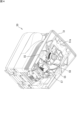
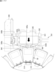
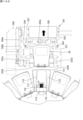
- FIG. 1 is a plan view showing an example of the overall configuration of a medicine packaging system according to an embodiment.
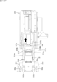
- FIG. 2 is a front view showing an example of the overall configuration of the medicine packaging system according to the embodiment.
- FIG. 3 is a plan view illustrating an example of a configuration of a cassette housing portion according to the embodiment.
- FIG. 4 is a perspective view showing the bottom surface of the cassette according to the embodiment.
- FIG. 5 is a front view of the cassette according to the embodiment.
- FIG. 6 is a side view of the cassette according to the embodiment.
- FIG. 7 is a view taken along line AA in FIG.
- FIG. 8 is a view taken along line BB in FIG.
- FIG. 9 is a perspective view illustrating an example of the configuration of a transport head according to the embodiment.
- FIG. 10 is a front view illustrating an example of the configuration of a transport head according to an embodiment.
- FIG. 11 is a plan view illustrating an example of the configuration of the stand according to the embodiment.
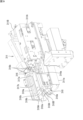
- FIG. 12 is a perspective view showing the positional relationship between the storage cylinder and the second transport unit.
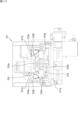
- FIG. 13 is a plan view illustrating an example of the configuration of a push-out mechanism according to an embodiment.
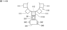
- FIG. 14A is a diagram illustrating an example of the transport of a cassette by the second transport unit.
- FIG. 14B is a diagram illustrating an example of the transport of the cassette by the second transport unit.
- FIG. 14C is a diagram showing an example of the transport of the cassette by the second transport unit.
- FIG. 15A is a plan view for explaining the first carry-in operation.
- FIG. FIG. 11 is a plan view illustrating an example of the configuration of the stand according to the embodiment.
- FIG. 12 is a perspective view showing the positional relationship between the storage cylinder and the second transport
- FIG. 15B is a side view for explaining the first loading operation.
- FIG. 15C is a plan view for explaining the first carry-in operation.
- FIG. 15D is a plan view for explaining the first carry-in operation.
- FIG. 15E is a plan view for explaining the first carry-in operation.
- FIG. 15F is a plan view for explaining the first carry-in operation.
- FIG. 15G is a side view for explaining the first loading operation.
- FIG. 15H is a plan view for explaining the first carry-in operation.
- FIG. 16A is a side view for explaining the first carrying-out operation.
- FIG. 16B is a plan view for explaining the first unloading operation.
- FIG. 16C is a plan view for explaining the first unloading operation.
- FIG. 16A is a side view for explaining the first carrying-out operation.
- FIG. 16B is a plan view for explaining the first unloading operation.
- FIG. 16C is a plan view for explaining the first unloading operation.
- FIG. 16D is a side view for explaining the first ejection operation.
- FIG. 16E is a plan view for explaining the first unloading operation.
- FIG. 16F is a plan view for explaining the first unloading operation.
- FIG. 16G is a plan view for explaining the first unloading operation.
- FIG. 16H is a plan view for explaining the first unloading operation.
- FIG. 17A is a plan view for explaining the second loading operation.
- FIG. 17B is a plan view for explaining the second loading operation.
- FIG. 17C is a plan view for explaining the second loading operation.
- FIG. 17D is a plan view for explaining the second loading operation.
- FIG. 17E is a plan view for explaining the second loading operation.
- FIG. 17F is a plan view for explaining the second loading operation.
- FIG. 17A is a plan view for explaining the second loading operation.
- FIG. 17B is a plan view for explaining the second loading operation.
- FIG. 17C is a plan view for
- FIG. 17G is a plan view for explaining the second loading operation.
- FIG. 17H is a plan view for explaining the second loading operation.
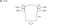
- FIG. 18A is a plan view for explaining the operation of the first roller and the second roller.
- FIG. 18B is a plan view for explaining the operation of the first roller and the second roller.
- FIG. 18C is a plan view for explaining the operation of the first roller and the second roller.
- FIG. 19A is a plan view for explaining the second unloading operation.
- FIG. FIG. 19B is a plan view for explaining the second unloading operation.
- FIG. 19C is a plan view for explaining the second unloading operation.
- FIG. 19D is a plan view for explaining the second unloading operation.
- FIG. 19E is a plan view for explaining the second unloading operation.
- FIG. 19F is a plan view for explaining the second unloading operation.
- FIG. 19G is a plan view for explaining the second unloading operation.
- FIG. 20 is
- the drug packaging system includes a first storage area for storing cassettes containing drugs and dispensing drugs from the stored cassettes, a second storage area for storing the cassettes to be transported to the first storage area, a first transport unit for transporting the cassettes within the second storage area, a second transport unit for transporting the cassettes from the second storage area to the first storage area, and a packaging unit for packaging the drugs dispensed from the cassettes stored in the first storage area in packages for each dosage unit.
- the second storage area may include a first storage position that stores the cassette that has been introduced into the drug packaging system from outside the drug packaging system, and a second storage position that stores the cassette that is to be transported to the first storage area, and the first transport unit may transport the cassette from the first storage position to the second storage position.
- This allows the cassette to be temporarily stored in the second storage position before being transported to the first storage area. While a cassette is stored in the second storage position, another cassette can be stored in the first storage position, and drugs can be dispensed from a cassette stored in the first storage area. Therefore, cassettes can be transported on a flexible schedule.
- the second storage position may be located between the first storage area and the first storage position. This allows the cassette to be efficiently transported from the first storage position to the first storage area via the second storage position located between the first storage position and the first storage area.
- the first storage areas may be arranged in a first direction, and the first storage position may be located in a second direction intersecting the first direction from the first storage areas. This makes it possible to reduce variation in the distance of the first storage position from each of the first storage areas, and to efficiently transport the cassette from the first storage position to the first storage area.
- a plurality of the second storage positions may be provided corresponding to the plurality of first storage areas. This allows the cassettes to be transported to each of the first storage areas to be temporarily stored in each of the second storage positions.
- the second transport unit may push the cassette from the second storage area to the first storage area. This makes it possible to prevent the configuration of the second transport unit from becoming complicated.
- the first storage area may be a cylindrical storage cylinder that can rotate in a circumferential direction. This allows the cassettes stored in the first storage area to be moved by rotating the storage cylinder, making it possible to transport the cassettes more efficiently.
- the storage cylinder may include a plurality of cassette storage sections capable of storing cassettes, the plurality of cassette storage sections may be arranged in a circumferential direction of the storage cylinder, and the second transport section may transport the cassette from the second storage area to one of the plurality of cassette storage sections. This allows many cassettes to be stored in the first storage area of limited size, and also prevents the configuration of the second transport section from becoming complicated.
- the multiple cassette storage sections can sequentially pass through specific loading positions, and the second transport section may load the cassette into the cassette storage section located at the loading position by transporting the cassette from the second storage area to the loading position. This allows the second transport section to transport the cassette to any cassette storage section of the storage cylinder.
- the drug packaging system may include a third storage area for storing cassettes containing drugs and dispensing the drugs from the stored cassettes, and a plurality of the storage cylinders may be arranged in a first direction, and the third storage area may be located in a space formed by two adjacent storage cylinders. This allows the plurality of storage cylinders and the second storage area to be efficiently arranged, and the entire drug packaging system to be made smaller.
- the drug packaging system may include a supply unit that supplies the drug dispensed from the cassette stored in the first storage area and the drug dispensed from the cassette stored in the third storage area to the packaging unit. This allows various combinations of drugs to be packaged together.
- the cassette stored in the first storage area may be a first cassette containing the same type of medicine
- the cassette stored in the third storage area may be a second cassette that can select the medicine to be contained from multiple types of medicine.
- the pharmaceutical packaging system may include a third conveying unit that conveys a second cassette to the third storage area by a second conveying path different from the first conveying path of the first cassette by the first conveying unit. This allows the first cassette and the second cassette to be individually conveyed by different paths.
- the first storage area may be located between the first transport path and the second transport path, the second storage area may be adjacent to a first portion of the first storage area that is close to the first transport path, and the third storage area may be adjacent to a second portion of the first storage area that is close to the second transport path. This allows each of the first cassette and the second cassette to be transported via an efficient route.
- the drug packaging system may include a housing that houses the first storage area, the second storage area, and the third storage area, the housing including a first surface, a second surface, and a third surface, the first surface and the second surface being two surfaces opposite each other, the third surface connecting the first surface and the second surface, the first transport path being closer to the first surface than the first storage area, the second transport path being closer to the second surface than the first storage area, and the third surface including a first transfer port for receiving the first cassette transported by the first transport path and a second transfer port for receiving the second cassette transported by the second transport path.
- the drug packaging system includes a cylindrical storage cylinder that can rotate in a circumferential direction for storing multiple cassettes containing drugs and dispensing drugs from the stored cassettes, a storage area adjacent to the storage cylinder and capable of storing multiple cassettes, a transport unit that transports the cassettes between the storage cylinder and the storage area, and a packaging unit that packages drugs dispensed from the cassettes stored in the storage cylinder in packaging material.
- a cylindrical storage cylinder that can rotate in a circumferential direction for storing multiple cassettes containing drugs and dispensing drugs from the stored cassettes
- a storage area adjacent to the storage cylinder and capable of storing multiple cassettes a transport unit that transports the cassettes between the storage cylinder and the storage area
- a packaging unit that packages drugs dispensed from the cassettes stored in the storage cylinder in packaging material.
- FIG. 1 is a plan view showing an example of the overall configuration of a medicine packaging system according to an embodiment
- FIG. 2 is a front view thereof.
- the drug packaging system 10 includes a packaging device 100, a winding device 200, a cassette storage device 300, a cassette distribution device 400, and an operating device 500.
- the packaging device 100 dispenses medicine from cassettes 50, 60 that contain the medicine, and packages the dispensed medicine in a package.
- the winding device 200 winds up a continuous packaging band of multiple packages in which medicine is packaged by the packaging device 100.
- the packaging device 100 can store multiple cassettes 50 and dispense medicines from the stored cassettes 50.
- a single cassette 50 contains the same type of medicine.
- the cassette 50 is a cassette dedicated to a specific type of medicine.
- the cassette 50 is an example of a "first cassette.”
- the packaging device 100 stores multiple cassettes 50, each corresponding to a different type of medicine.
- the packaging device 100 can store multiple cassettes 60 and dispense medicines from the stored cassettes 60.
- a single cassette 60 contains a drug selected from multiple types of drugs other than the drug contained in cassette 50.
- cassette 60 is a cassette that can accommodate multiple types of drugs.
- cassette 60 is capable of adjusting the size of the drug discharge path. By adjusting the size of the discharge path according to the size of the drug selected from multiple types of drugs, cassette 60 becomes able to dispense this drug.
- Cassette 60 is an example of a "second cassette.” For example, a drug that is used frequently is contained in cassette 50, and a drug that is used less frequently is contained in cassette 60.
- the multiple packaging devices 100 and the multiple winding devices 200 are arranged in a row.
- the winding devices 200 correspond one-to-one to the packaging devices 100.
- the packaging devices 100 and the corresponding winding devices 200 are arranged next to each other. In other words, the packaging devices 100 and the winding devices 200 are arranged alternately in a row.
- a drug packaging system 10 is shown that includes three packaging devices 100 and three winding devices 200.
- the number of packaging devices 100 and winding devices 200 is not limited to three.
- the drug packaging system 10 may include one packaging device 100 and one winding device 200, two packaging devices 100, or four or more packaging devices 100 and winding devices 200.
- the direction in which the packaging device 100 and the winding device 200 are lined up will be referred to as the "left-right direction” or “lateral direction.”
- the horizontal direction perpendicular to the left-right direction will be referred to as the “front-back direction.”
- the "left-right direction,” “front-back direction,” and “up-down direction” used below are directions common to the entire pharmaceutical packaging system 10, and are not individual directions for each unit.
- the cassette storage device 300 is disposed behind the packaging device 100 and the winding device 200.
- the cassette storage device 300 can store multiple cassettes 50.
- the filling station 450 is located to the left of the leftmost packaging device 100.
- the filling station 450 includes a cassette distribution device 400 and an operating device 500.
- the operating device 500 is used by an operator to operate the drug packaging system 10.
- the operating device 500 is disposed on the leftmost side of the drug packaging system 10.
- the operating device 500 includes an input device 510 for the operator to input drug information.
- the input device 510 includes, for example, a barcode reader, an RFID (Radio Frequency Identification) reader, and a display.
- a barcode reader for example, a drug container containing a drug is supplied from a pharmaceutical company.
- the drug container is provided with a barcode that records information about the drug contained therein.
- the operator reads the barcode of the drug container using a barcode reader. This allows information about the drug (including the drug ID) to be input to the operating device 500.
- An RF tag is attached to the cassette 50, and a cassette number for identifying the cassette 50 and the drug ID of the drug to be contained in the cassette are recorded on this RF tag.
- the operator reads the RF tag of the cassette 50 using an RFID reader. The read drug ID and cassette number are shown on the display, allowing the operator to match the cassette number with the drug ID.
- the operating device 500 includes a first transfer opening 520 for receiving the cassette 50.
- the first transfer opening 520 allows the cassette 50 to be placed therein, and opens on the left side of the operating device 500.
- the first transfer opening 520 has a door, and at the back of the door there is a platform for placing the cassette 50. The operator can place a new cassette 50 in the first transfer opening 520.
- the operating device 500 includes a second transfer port 530 for receiving the cassette 60.
- the second transfer port 530 is capable of placing the cassette 60 and opens on the left side of the operating device 500.
- the second transfer port 530 has a door and has a platform behind the door for placing the cassette 60. The operator can place a new cassette 60 in the second transfer port 530.
- the housing 11 includes a panel-shaped front surface 11a, a rear surface 11b, a left side surface 11c, and a right side surface 11d.
- the front surface 11a constitutes the front surface of the packing device 100 and the winding device 200.
- the rear surface 11b constitutes the rear surface of the cassette storage device 300.
- the left side surface 11c constitutes the left side surface of the operating device 500 (hereinafter also referred to as the "operation surface") and the left side surface of the cassette storage device 300.
- the right side surface 11d constitutes the right side surface of the rightmost winding device 200 and the right side surface of the cassette storage device 300. Note that part of the front surface 11a is omitted in FIG. 2.
- the first and second transfer ports 520 and 530 open on the operation surface 11c.
- the input device 510 is also provided on the operation surface 11c. This allows the operator to concentrate on the operation surface 11c while operating the drug packaging system 10.
- the cassette distribution device 400 can transport the cassette 50 between the first transfer opening 520 and the first cassette transfer position 410.
- the first cassette transfer position 410 faces the cassette storage device 300.
- the first cassette transfer position 410 is a position for transferring the cassette 50 between the cassette distribution device 400 and the cassette storage device 300.
- the cassette storage device 300 includes a first transport section 310.
- the first transport section 310 transports the cassette 50 inside the cassette storage device 300.
- the cassette storage device 300 transports and stores the cassette 50 received at the first cassette transfer position 410 by the first transport section 310.
- the cassette storage device 300 is an example of a "second storage area.”
- the cassette storage device 300 includes storage shelves 320, 350 and a cassette table 330.
- the storage shelves 320, 350 can store multiple cassettes 50.
- Each of the multiple cassette tables 330 is adjacent to the packing device 100 at the rear of the packing device 100.
- the cassette tables 330 are provided corresponding to each of the storage cylinders 110 described below.
- the cassette table 330 stores the cassettes 50 to be transported to the packing device 100.
- the cassette table 330 is a preparation area for preparing the transport of the cassettes 50 to the packing device 100.
- the storage shelf 320 is an example of a "first storage position"
- the cassette table 330 is an example of a "second storage position”.
- the storage shelf 320 may not only be provided behind the cassette table 330, but may also be added in substantially the same vertical plane as the cassette table 330 (i.e., lined up in the left-right direction with the cassette table 330). This allows the capacity of the cassette 50 to be increased.
- multiple cassette tables 330 are arranged in a row at regular intervals in the left-right direction.
- the multiple storage shelves 350 are arranged on the left and right of the cassette table 330 at the rear of the packaging device 100. That is, the storage shelves 350 are arranged between adjacent cassette tables 330 in the left-right direction. In other words, the cassette table 330 is arranged between two storage shelves 350. For example, in one cassette table 330, the left storage shelf 350 corresponds to the "first storage” and the right storage shelf 350 corresponds to the "second storage.”
- Storage shelf 320 is positioned at a certain distance behind cassette table 330 and storage shelf 350. Storage shelf 320 corresponds to the "third storage cabinet.”
- the first transport section 310 transports the cassettes 50 between the storage shelf 320 and the cassette table 330 and storage shelf 350. That is, a transport space is provided behind the cassette table 330 and storage shelf 350 for the first transport section 310 to transport the cassettes 50.
- the storage shelf 320 is disposed behind the transport space.
- the cassette storage device 300 further includes a second conveying section 340.
- the second conveying section 340 conveys the cassette 50 from the cassette table 330 to the packaging device 100.
- the cassette 50 conveyed from the cassette table 330 to the packaging device 100 is stored within the packaging device 100.
- the cassette tables 330 are provided in six locations, each corresponding to a storage cylinder 110 described below.
- a conveying device 600 is disposed in front of the multiple packaging devices 100.
- the conveying device 600 is capable of conveying the cassettes 60.
- the conveying device 600 is an example of a "third conveying section.”
- the cassette distribution device 400 can transport the cassette 60 between the second transfer opening 530 and the second cassette transfer position 420.
- the second cassette transfer position 420 faces the left end portion of the transport device 600.
- the second cassette transfer position 420 is a position for transferring the cassette 60 between the cassette distribution device 400 and the transport device 600.
- the conveying device 600 conveys the cassette 60 received at the second cassette transfer position 420 to one of the multiple packaging devices 100.
- the conveying device 600 is an example of a "third conveying section.”
- the cassette 60 conveyed by the conveying device 600 is stored in the packaging device 100.
- the packaging device 100 includes a storage cylinder 110 capable of storing a plurality of cassettes 50 each containing medicines (tablets) for each medicine type.
- the storage cylinder 110 is cylindrical and configured to be rotatable in the circumferential direction.
- the storage cylinder 110 is a storage area for storing the cassette 50.
- the storage cylinder 110 is capable of dispensing medicines from the stored cassette 50.
- the storage cylinder 110 is an example of a "first storage area.”
- the storage cylinder 110 includes a plurality of cassette accommodating sections 111 capable of accommodating cassettes 50.
- the plurality of cassette accommodating sections 111 are arranged in the circumferential direction and the vertical direction of the storage cylinder 110.
- One cassette 50 is accommodated (held) in one cassette accommodating section 111.
- the central cylinder of the storage cylinder 110 is hollow, and the internal space serves as a passageway for the medicine.
- the cassette accommodating section 111 is provided with a chute through which the medicine dispensed from the cassette 50 passes, and the chute of each cassette accommodating section 111 is connected to the internal space of the storage cylinder 110. The medicine dispensed from the cassette 50 passes through the chute and the internal space and falls below the packaging device 100.
- two storage cylinders 110 are provided in one packaging device 100.
- the two storage cylinders 110 are lined up in the left-right direction within the packaging device 100.
- the number of storage cylinders 110 included in the packaging device 100 is not limited to two.
- the packaging device 100 may be provided with one storage cylinder 110, or may be provided with three or more storage cylinders 110.
- the packaging device 100 is provided with multiple storage cylinders 110, the multiple storage cylinders 110 are lined up in a row in the left-right direction.
- the left-right direction is an example of the "first direction".
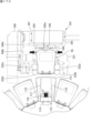
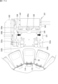
- FIG. 3 is a plan view showing an example of the configuration of the cassette storage section according to the embodiment.
- the cassette storage sections 111 are arranged in a circular ring shape.
- a set of the cassette storage sections 111 arranged in a circular ring shape are arranged in a plurality of stages in the vertical direction.
- the cassette storage sections 111 are arranged on one plane. That is, in the storage cylinder 110, the cassette storage sections 111 are arranged in a circular ring shape on each of a plurality of planes arranged in the vertical direction.
- the storage cylinder 110 can rotate around the central axis of the ring.
- the set of the cassette storage sections 111 in each stage can move in a circular ring shape on the corresponding plane.
- the set of the cassette storage sections 111 arranged in a circular ring shape corresponds to a "cassette holding section.”
- Each cassette storage section 111 is configured in a flat platform shape, and the cassette 50 can be placed on the upper surface.
- the cassette storage section 111 includes a table 113 that is fan-shaped with a missing tip when viewed from above, and a holding section 114 for holding the cassette 50 placed on the table 113.
- the table 113 is a platform on which the cassette 50 is placed.
- the holding section 114 is provided on the tip side of the fan shape of the table 113.
- the holding section 114 is provided with an inlet 114a through which the medicine dispensed from the cassette 50 is inserted.
- the inlet 114a is connected to a chute 114b.
- the cassette storage section 111 includes a locking section 115 for locking the retention of the cassette 50.
- the locking section 115 is two arms that extend radially outward from the retention section 114 in a sector shape.
- a protrusion 115a is provided at the longitudinal middle of each of the two locking sections 115.
- the protrusion 115a of the right locking section 115 protrudes to the right, and the protrusion 115a of the left locking section 115 protrudes to the left.
- FIG. 4 is a perspective view showing the bottom surface of a cassette according to an embodiment.
- An outlet 57 for discharging the medicine is opened in the bottom surface 51 of the cassette 50.
- a pair of engagement portions 55 that engage with the lock portion 115 of the cassette storage portion 111 are provided on the bottom surface of the cassette 50.
- the engagement portions 55 are biased in a direction toward each other by a spring (not shown), and can move in a direction away from each other.
- the pair of locking sections 115 come into contact with the pair of engaging sections 55. More specifically, the left side of the right engaging section comes into contact with the right side surface of the right locking section 115, and the right side of the left engaging section comes into contact with the left side surface of the left locking section 115.
- the engaging section 55 comes into contact with the protrusion 115a. The two engaging sections 55 move away from each other along the protrusion 115a, and when they pass the protrusion 115a, they return to their original positions due to the biasing force. This causes the locking sections 115 and the engaging sections 55 to engage, locking the cassette 50 in place.
- a gear 56 is provided on the bottom side of cassette 50.
- gear 56 meshes with gear 116 provided on holding portion 114.
- gear 116 is driven by a motor (not shown)
- gear 56 rotates, and a drug dispensing mechanism (not shown) built into cassette 50 operates.
- the drug dispensing mechanism dispenses a predetermined number of drugs from outlet 57, and the dispensed drugs are fed into inlet 114a.
- FIG. 5 is a front view of a cassette according to an embodiment (viewed from the outside of the sector), and FIG. 6 is a side view thereof.
- recesses 53 are formed in the vertical middle portion in the range from the radial middle position to the outer edge. In other words, the radial outer portion of the cassette 50 has a reduced width in the vertical middle portion. The recesses 53 are used as a point for the user to grip the cassette 50.
- the lower bottom of the recess 53 of the cassette 50 protrudes from both sides of the cassette 50. More specifically, below the recess 53 described above, a protrusion 52 is provided that protrudes to the side.
- the outer edge shape of the pair of protrusions 52 corresponds to the outer edge shape of the portion of the cassette 50 above the recess 53. In other words, the outer edge of the protrusion 52 forms part of a sector with a missing tip in a plan view.
- the upper surface of the protrusion 52 is an inclined surface 52a that slopes downward toward the outside. Because the protrusion 52 forms part of a sector with its tip missing in a plan view, the outer edge shape of the inclined surface 52a slopes downward toward the outside when viewed from the front, that is, when viewed in the radial direction of the sector toward the center (angle ⁇ in FIG. 5). In other words, the outer edge of the inclined surface 52a in a front view includes a straight line that intersects with a straight line extending along the bottom surface of the cassette 50 at an angle ⁇ .
- a button 54 for unlocking the locking portion 115 is disposed in the recess 53.
- the button 54 works in conjunction with the engagement portions 55.
- the pair of engagement portions 55 move in directions away from each other. This releases the engagement (lock) between the locking portion 115 and the engagement portions 55.
- each of the packaging devices 100 includes a cassette storage unit 120.
- the cassette storage unit 120 is a storage area that stores a plurality of cassettes 60.
- the cassette storage unit 120 can dispense medicines from the stored cassettes 60.
- the cassette storage unit 120 is an example of a "third storage area.”
- the cassette storage unit 120 includes a plurality of cassette storage sections 121 capable of storing cassettes 60.
- the plurality of cassette storage sections 121 are arranged in the vertical direction.
- One cassette 60 is stored in one cassette storage section 121.
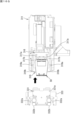
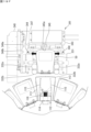
- the cassette storage unit 120 is located in the space formed by two adjacent storage cylinders 110. Specifically, two spaces that are essentially triangular in plan view are formed between two adjacent cylindrical storage cylinders 110. The cassette storage unit 120 is disposed in the front space of the two triangular spaces. This increases the storage capacity of the cassettes 50, 60 in the packaging device 100 and enables the packaging device 100 to be made more compact.
- the packaging device 100 further includes a manual distribution unit 130.
- the manual distribution unit 130 is also referred to as a DTA (Detachable Tablet Adapter).
- the manual distribution unit 130 is used to dispense tablets that are not suitable for dispensing from the cassettes 50 and 60, such as half tablets or 1 ⁇ 4 tablets that are less than one tablet.
- the manual distribution unit 130 is provided below the storage cylinder 110 and the cassette storage unit 120.
- the manual distribution unit 130 is a drawer-like box body, and inside it, multiple compartments capable of containing medicines are arranged in a lattice pattern. When using the manual distribution unit 130, the operator pulls out the manual distribution unit 130, places medicines in the compartments, and then returns the manual distribution unit 130.
- the packaging device 100 further includes a supply section 140 and a packaging section 150.
- the supply unit 140 supplies the medicine dispensed from the cassette 50 stored in the storage cylinder 110, the medicine dispensed from the cassette 60 stored in the cassette storage unit 120, and the medicine dispensed from the manual distribution unit 130 to the packaging unit 150.
- the supply unit 140 includes a hopper 141 and a hopper 142.
- the hoppers 141 and 142 are in an inverted cone shape, an inverted triangular pyramid shape, an inverted square pyramid shape, etc.
- the hopper 141 supplies the medicine dispensed from the cassette 50 stored in the storage cylinder 110, and the medicine dispensed from the cassette 60 stored in the cassette storage unit 120 to the packaging unit 150.
- the hopper 142 supplies the medicine dispensed from the manual distribution unit 130 to the packaging unit 150.
- the packaging unit 150 packages the medicine supplied from the supply unit 140 in a package 71.
- the packaging band 70 is composed of multiple packages 71 arranged in a continuous band shape.
- the packages 71 are bag-shaped and contain the medicine.
- the packaging unit 150 rotatably holds a roll 73 of the sheet 72 before the packaging band 70 is formed.
- the packaging unit 150 pulls out the sheet 72 from the roll 73 and forms a bag-shaped pocket by gluing (heat sealing) the folded sheet 72 over the entire width at a portion of the longitudinal direction.
- the medicine is dropped into the pocket below the supply unit 140.
- the entire width and a portion of the longitudinal direction of the sheet 72 (the edge opposite the fold) are then glued, and the two open sides of the pocket are sealed to form a rectangular package 71.
- the packaging unit 150 has a function for inspecting medicine before it is packaged.
- the packaging unit 150 includes a camera (not shown) that captures an image of the medicine before it is dropped into a pocket. The image captured by the camera is analyzed to inspect whether the desired medicine has been packaged.
- the winding device 200 winds up the wrapping strip 70 coming from the packaging section 150 into a roll.
- the wrapping strip 70 wound up by the winding device 200 is collected by an operator.
- FIG. 7 is a view taken along line AA in FIG.
- the storage shelf 320 includes a plurality of shelves 321 arranged vertically. Each shelf 321 has a plurality of storage sections 322 arranged horizontally at regular intervals. One storage section 322 can store one cassette 50. That is, the storage shelf 320 has a plurality of storage sections 322 arranged in rows and columns.
- the first transport unit 310 is disposed in front of the storage shelf 320 (see FIG. 1).
- the first transport unit 310 includes a transport head 311, a lifting unit 312, and a horizontal drive unit 313.
- the transport head 311 can hold the cassette 50 by a holding mechanism.
- the lifting unit 312 includes a rail 314 extending in the vertical direction and a motor, and moves the transport head 311 in the vertical direction along the rail 314.
- the horizontal drive unit 313 includes a rail 315 extending in the left-right direction and a motor, and moves the transport head 311 and the lifting unit 312 in the left-right direction along the rail 315. That is, the transport head 311 can move in the vertical direction and the left-right direction in front of the storage shelf 320.
- the transport head 311 is configured to be rotatable 180 degrees horizontally by a motor.
- the transport head 311 can rotate between facing forward and facing backward.
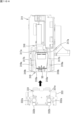
- FIG. 8 is an arrow view taken along line B-B in FIG. 1.
- the first conveying section 310 is disposed behind the cassette distribution device 400, the packaging device 100, the winding device 200, and the storage cabinet 350. In other words, the first conveying section 310 is disposed between the packaging device 100 and the storage shelf 320, or in other words, between the storage cabinets 350 and 320.
- storage shelf 350 includes multiple shelves 321 arranged in the vertical direction. Each shelf 321 has multiple storage sections 322 arranged in the horizontal direction at regular intervals. In storage shelf 350, multiple storage sections 322 are arranged in rows and columns.
- the first transport section 310 moves the transport head 311 up and down, left and right, or both, to a position facing the first cassette transfer position 410.
- the transport head 311 holds the cassette 50 located at the first cassette transfer position 410, and pulls the cassette 50 rearward from the first cassette transfer position 410. This enables the first transport section 310 to receive the cassette 50 from the cassette distribution device 400.
- Figure 9 is a perspective view showing an example of the configuration of the transport head 311 according to an embodiment
- Figure 10 is a front view thereof.
- the transport head 311 includes a base portion 311a, a contact portion 316, and a support portion 318.
- the base portion 311a is equipped with a contact portion 316 and a support portion 318.
- the contact portion 316 can move in the longitudinal direction.
- the transport head 311 takes in or out the cassette 50 from the storage 320
- the transport head 311 faces in a direction facing the storage 320, i.e., toward the rear.
- the contact portion 316 can move backward and forward.
- the transport head 311 takes in or out the cassette 50 from the storage 350 or the cassette table 330
- the transport head 311 faces in a direction facing the storage 320 or the cassette table 330, i.e., toward the front.
- the contact portion 316 can move forward and backward.
- the following description will be given of the state in which the transport head 311 faces forward.
- the contact portion 316 is used to come into contact with the cassette 50 and hold the cassette 50.
- the contact portion 316 includes a protrusion 316a that protrudes upward and two holding plates 316b.
- the protrusion 316a is located at the tip of the contact portion 316, and the holding plates 316b are located behind the protrusion 316a.
- a recess 51a is provided on the bottom surface 51 of the cassette 50.
- the recess 51a is provided on the front side of the cassette 50, that is, on the outermost part of the sector.
- the protrusion 316a can be inserted into the recess 51a.
- the holding plate 316b comes into contact with the front surface of the cassette 50, or is located at a small distance behind the cassette 50. If the cassette 50 is lifted only by the contact portion 316 with the protrusion 316a inserted into the recess 51a, there is nothing to support the bottom surface of the cassette 50, and the rear side of the cassette 50 (i.e., the tip side of the sector) drops. At this time, the holding plate 316b comes into contact with the front surface of the cassette 50. Therefore, the cassette 50 is held by the protrusion 316a and the holding plate 316b, and does not fall off the conveying head 311.
- the contact portion 316 has linear guide carriages 317a at both the left and right ends.
- the support portion 318 is provided with a pair of rails 317b, and each carriage 317a engages with the rails 317b and can move in the front-rear direction along the rails 317b. This allows the contact portion 316 to move in the front-rear direction relative to the support portion 318.
- the base portion 311a is provided with a motor 311A for moving the contact portion 316.
- the power of the motor 311A is transmitted to the contact portion 316, and the contact portion 316 moves linearly along the rail 317b.
- the support portion 318 is disposed below the contact portion 316.
- the support portion 318 can move forward and backward.
- the support part 318 has guide parts 319a including linear guide carriages on both the left and right ends.
- a pair of rails 319b is provided on the base part 311a, and the carriages provided on each guide part 319a engage with the rails 319b and can move in the front-rear direction along the rails 319b. This allows the support part 318 to move in the front-rear direction relative to the base part 311a. In other words, the contact part 316 and the support part 318 can move in the front-rear direction independently of each other.
- the guide portions 319a are spaced apart from each other in the left-right direction. Each guide portion 319a extends in the front-rear direction.
- the two guide portions 319a have a cutout on the underside of the opposing surface. That is, one corner of the rectangular bar of the guide portion 319a is missing along the entire longitudinal direction, and the pressing surface 319A, which is an inclined surface, extends in the longitudinal direction.
- the inclination angle of the pressing surface 319A is the same angle ⁇ as the angle ⁇ of the protrusion 52 of the cassette 50 when viewed from the front (see FIG. 5).
- the base portion 311a is provided with a motor 311B for moving the support portion 318.
- the power of the motor 311B is transmitted to the support portion 318, and the support portion 318 moves linearly along the rail 319b.
- the support portion 318 has a pair of first rollers 318a and a pair of second rollers 318b at its tip.
- the pair of first rollers 318a are attached to a shaft 318A extending in the left-right direction so as to be aligned in the left-right direction. Each first roller 318a can rotate around the shaft 318A.
- a shaft 318B extending in the left-right direction is arranged behind the shaft 318A.
- the pair of second rollers 318b are attached to the shaft 318B so as to be aligned in the left-right direction. Each second roller 318b can rotate around the shaft 318B.
- the shafts 318A and 318B are arranged at the same height, and the first rollers 318a and the second rollers 318b have the same radius.
- the first roller 318a and the second roller 318b are used to support the cassette 50.
- the protrusion 316a is inserted into the recess 51a of the cassette 50 and the first roller 318a and the second roller 318b are located forward of the protrusion 316a, the bottom surface of the cassette 50 comes into contact with the upper end points of the first roller 318a and the second roller 318b.
- the contact portion 316 moves relative to the support portion 318 in the front-to-rear direction
- the cassette 50 moves on the first roller 318a and the second roller 318b, and the first roller 318a and the second roller 318b rotate as the cassette 50 moves.
- the pair of guide portions 319a are spaced apart by a distance corresponding to the maximum width of the cassette 50, specifically, a distance slightly greater than the maximum width of the cassette 50. Therefore, the cassette 50 can move back and forth between the guide portions 319a on the support portion 318. Furthermore, as described above, the guide portion 319a is provided with a pressing surface 319A. Since the angle ⁇ of the pressing surface 319A corresponds to the angle ⁇ of the bottom of the cassette 50, the guide portion 319a engages with the recess 53 of the cassette 50, and the pressing surface 319a is positioned above the protrusion 52 of the cassette 50. Therefore, when the cassette 50 moves on the support portion 318, the upward movement of the cassette 50 is suppressed, and the cassette 50 is prevented from falling off the support portion 318.
- the first transport unit 310 rotates the transport head 311 holding the cassette 50 to face it to the right or left.
- the first transport unit 310 moves the transport head 311 in this state in the vertical and horizontal directions, or both.
- the first transport unit 310 positions the transport head 311 in front of one of the empty storage sections 322 of the storage shelf 320, and rotates the transport head 311 horizontally (forward and backward) to face it backward (toward the rear surface 11b).
- the transport head 311 moves the cassette 50 it is holding backward, so that the cassette 50 is stored in the storage section 322.
- the transport head 311 releases the cassette 50, completing the movement of the cassette 50 to the storage shelf 320.
- the first transport unit 310 rotates the transport head 311 that has released the cassette 50, and faces it to the right or left. In this state, the first transport unit 310 can move the transport head 311 in the vertical and horizontal directions.
- the first transport unit 310 can take out a cassette 50 from one storage unit 322 and transport the cassette 50 to a storage unit 322 that is in a different row, column, or both from the first storage unit 322. That is, the first transport unit 310 moves the transport head 311 to a position facing one storage unit 322, and rotates the transport head 311 horizontally to face backward. The transport head 311 holds the cassette 50 stored in the storage unit 322 and pulls it out forward from the storage unit 322.
- the first transport unit 310 rotates the transport head 311 holding the cassette 50 to face it to the right or left.
- the first transport unit 310 moves the transport head 311 in this state up and down, left and right, or both.
- the first transport unit 310 positions the transport head 311 in front of the target storage unit 322 (in the direction approaching the front surface 11a), and rotates the transport head 311 horizontally to face it backwards.
- the transport head 311 moves the cassette 50 it is holding to the rear, whereby the cassette 50 is stored in the storage unit 322.
- the transport head 311 releases the cassette 50, completing the movement of the cassette 50 within the storage shelf 320.
- the cassette table 330 includes a number of stands 331.
- the stand 331 is a plate-like member capable of supporting one cassette 50.
- the same number of stands 331 as the number of stages in the storage cylinder 110 are lined up in the vertical direction.
- Each stand 331 corresponds to one stage of the storage cylinder 110.
- the stands 331 are positioned at the same height as the corresponding stage of the storage cylinder 110.
- FIG. 11 is a plan view showing an example of the configuration of a stand 331 according to an embodiment.
- the stand 331 includes a flat body portion 331a and a base portion 333.
- the body portion 331a is disposed on the base portion 333 and is supported by the base portion 333.
- the main body 331a has a T-shape in a plan view. That is, the main body 331a includes a first portion 334a that corresponds to the wide part of the T, and a second portion 334b that corresponds to the narrow part of the T. In the main body 331a, the first portion 334a is located at the rear, and the second portion 334b is located at the front.
- the width (left-right length) of the first portion 334a is greater than the width of the cassette 50.
- the width of the second portion 334b is smaller than the width of the cassette 50.
- a pair of first rollers 332a and a pair of second rollers 332b are arranged on both sides of the second portion 334b. Each of the first rollers 332a and the second rollers 332b is attached to the base portion 333. The first rollers 332a are arranged rearward of the second rollers 332b.
- the pair of first rollers 332a are biased by a spring in a direction in which they approach each other (left-right direction). That is, the pair of first rollers 332a can move in a direction in which they move away from each other. In a natural state in which the pair of first rollers 332a are closest to each other, they are separated from each other by a distance that is greater than the width of the narrowest part of the cassette 50 (the part closest to the center of the sector in the radial direction), which is a sector with a missing tip in a plan view, and smaller than the width of the widest part of the cassette 50 (the part farthest from the center of the sector in the radial direction).
- the distance between the pair of first rollers 332a at this time is the distance between the closest points of the two first rollers 332a.
- the pair of first rollers 332a can move away from each other by a distance equal to or greater than the width of the widest part of the cassette 50.
- the pair of second rollers 332b are biased by a spring in a direction in which they approach each other (left-right direction). That is, the pair of second rollers 332b can move in a direction away from each other.
- the pair of second rollers 332b are in their natural state in which they are closest to each other, they are separated from each other by a distance that is greater than the width of the narrowest part of the cassette 50, which is a sector with a missing tip in a plan view, and smaller than the width of the widest part of the cassette 50.
- the distance between the pair of second rollers 332b at this time is the distance between the closest points of the two second rollers 332b.
- the pair of second rollers 332b can move away from each other by a distance equal to or greater than the width of the widest part of the cassette 50.
- the distance between the pair of second rollers 332b in the natural state is greater than the distance between the pair of first rollers 332a in the natural state.
- the cassette 50 slides from the front end of the main body 331a to the table 113.
- the cassette 50 comes into contact with the first roller 332a and the second roller 332b.
- the first roller 332a and the second roller 332b come into contact with both side surfaces of the cassette 50, and while the cassette 50 passes through the first roller 332a and the second roller 332b, the pair of first rollers 332a move away from each other due to the width of the cassette 50, and the pair of second rollers 332b move away from each other.
- This allows the cassette 50 to be transported without tilting horizontally, and the central axis of the cassette 50 in the left-right direction is aligned with the central axis of the table 113 in the left-right direction.
- the second conveying section 340 corresponds one-to-one to the cassette table 330.
- the second conveying section 340 is disposed behind the corresponding cassette table 330.
- Figure 12 is a perspective view showing the positional relationship between the storage cylinder 110 and the second conveying section 340.
- the second transport section 340 includes a push-out mechanism 341 and a rail 342.
- the rail 342 extends in the vertical direction at a position behind the corresponding cassette table 330.
- the push-out mechanism 341 has a built-in motor and can move in the vertical direction along the rail 342.
- the push-out mechanism 341 moves upward or downward to position itself behind the stand 331 in which the cassette 50 is placed. In this state, the push-out mechanism 341 moves the cassette 50 forward, thereby transporting the cassette 50 from the stand 331 to the cassette storage section 111.
- Figure 13 is a plan view showing an example of the configuration of the push-out mechanism 341 according to an embodiment.
- the pushing mechanism 341 includes a pushing member 347 and a base portion 348.
- the pushing member 347 is attached to the base portion 348 so as to be movable in the front-rear direction.
- the pushing member 347 has a linear guide carriage 346a at its left end.
- the base portion 348 is provided with a rail 346b, and the carriage 346a engages with the rail 346b and is movable in the front-rear direction along the rail 346b. This allows the pushing member 347 to move in the front-rear direction relative to the base portion 348.
- a motor is provided on the base portion 348 to move the push-out member 347 in the forward and backward directions.
- the power of the motor is transmitted to the push-out member 347, and the push-out member 347 moves in the forward and backward directions along the rail 346b.
- a catcher 344 consisting of a pair of claws is provided on the front surface of the push-out member 341.
- the pair of claws of the catcher 344 are arranged at a distance from each other in the left-right direction on the front surface of the push-out member 341.
- the pair of claws can move in the left-right direction so as to move closer to or away from each other.
- a motor (not shown) is mounted on the push-out member 341, and the power of the motor moves the claws so as to move closer to or away from each other.
- the catcher 344 is used to hold the cassette 50. That is, the catcher 344 holds the cassette 50 by pinching the recesses 53 on both sides of the cassette 50 from both sides.
- the catcher 344 is also used to press the button 54 provided in the recess 53 of the cassette 50. That is, when the pair of claws come close to each other, the claws come into contact with the button 54, and the button 54 is pressed in.
- a contact portion 345 is provided on the front surface of the push-out member 341 between a pair of claw portions of the catcher 355.
- the contact portion 345 protrudes forward from the front surface of the push-out member 341, and has a contact surface 345a, which is a flat surface facing forward, at its tip.
- the contact surface 345a is used to push out the cassette 50. That is, when the pair of claw portions are separated in the left-right direction and the hold of the cassette 50 by the catcher 344 is released, the push-out member 341 moves forward, causing the contact surface 345a to come into contact with the rear surface of the cassette 50. When the push-out member 341 moves further forward, the cassette 50 is pushed forward.
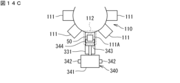
- Figures 14A to 14C show an example of the transport of the cassette 50 by the second transport unit 340.
- the loading position 112 is a position for loading and unloading the cassette 50 into the cassette storage section 111.
- the second transport section 340 can transport the cassette 50 to the cassette storage section 111 positioned at the loading position 112, and can unload the cassette 50 from the cassette storage section 111 positioned at the loading position 112.
- the storage cylinder 110 can be rotated clockwise or counterclockwise by a motor.
- the cassette storage section 111 that is intended to store the cassette 50 is indicated by diagonal lines as cassette storage section 111A.
- the cassette storage section 111A is positioned at the loading position 112 (FIG. 14B).
- the push-out mechanism 341 moves upward or downward and is positioned at the stage where the cassette storage section 111A is provided.
- the push-out mechanism 341 includes a push-out member 343 (FIG. 14C).
- the push-out mechanism 341 can move the push-out member 343 in the front-rear direction by a motor.
- the push-out member 343 is positioned behind the stand 331.
- the push-out mechanism 341 pushes the cassette 50 on the stand 331 forward by moving the push-out member 343 forward.
- the second transport section 340 transports the cassette 50 from the stand 331 to the cassette storage section 111A at the loading position 112.
- the cassette storage device 300 can remove the cassettes 50 stored in the packaging device 100 and transport the removed cassettes 50 to the storage shelf 320.
- the packaging device 100 detects a cassette 50 stored in the storage cylinder 110 that needs to be refilled with medicine due to a shortage in which all medicines have been dispensed, or a cassette 50 that needs to be removed because it has been left unused for a certain period of time, the packaging device 100 rotates the storage cylinder 110 in a circumferential direction and positions the cassette storage section 111 that stores the unnecessary cassette 50 at the loading position 112.
- the push-out mechanism 341 moves upward or downward and is positioned at a stage where a cassette storage section 111 for storing unnecessary cassettes 50 is provided.
- the push-out mechanism 341 includes a catcher 344 capable of clamping the cassette 50.
- the catcher 344 is movable in the front-rear direction together with the push-out member 343.
- the push-out mechanism 341 moves the catcher 344 forward, and the catcher 344 holds the unnecessary cassette 50 by clamping it.
- the push-out mechanism 341 moves the catcher 344 holding the cassette 50 backward, and transfers the cassette 50 to the stand 331.
- the catcher 344 releases its hold on the cassette, and the push-out mechanism 341 moves upward or downward.
- the first transport unit 310 moves the transport head 311 up and down, left and right, or both, and positions it opposite the stand 331 on which the unnecessary cassette 50 is placed.
- the transport head 311 holds the cassette 50 placed on the stand 331, and pulls the cassette 50 rearward from the stand 331.
- the first transport unit 310 rotates the transport head 311 holding the cassette 50 to face it to the right or left.
- the first transport unit 310 moves the transport head 311 in this state in the vertical and horizontal directions, or both.
- the first transport unit 310 positions the transport head 311 in front of one of the empty storage sections 322 of the storage shelves 320 and 350, and rotates the transport head 311 horizontally to face it backward or forward.
- the transport head 311 moves the cassette 50 it is holding backward or forward, so that the cassette 50 is stored in the storage section 322.
- the transport head 311 releases the cassette 50, and the movement of the cassette 50 to the storage shelf 320 or 350 is completed.
- the first conveying unit 310 moves the conveying head 311 to a position facing the storage unit 322 in which the cassette 50 to be removed is stored, and rotates the conveying head 311 horizontally to face backward or forward.
- the conveying head 311 holds the cassette 50 stored in the storage unit 322 and pulls it out forward or backward from the storage unit 322.
- the first transport unit 310 rotates the transport head 311 holding the cassette 50 to face it to the right or left.
- the first transport unit 310 moves the transport head 311 in this state in the vertical and/or horizontal directions.
- the first transport unit 310 positions the transport head 311 opposite the first cassette transfer position 410 and rotates the transport head 311 horizontally to face it forward.
- the transport head 311 moves the cassette 50 it is holding forward, which positions the cassette 50 at the first cassette transfer position 410.
- the transport head 311 releases the cassette 50, completing the movement of the cassette 50 to the first cassette transfer position 410.
- the cassette distribution device 400 transfers the cassette 50 placed at the first cassette transfer position 410 to the first transfer port 520.
- the operator can remove the cassette 50 from the first transfer port 520.
- the cassette 50 is filled with medicine (tablets) (inventory update) and returned to the first transfer port 520, where it is stored in the storage cylinder 110 or cassette storage device 300 as described above.
- Figures 15A to 15H are diagrams for explaining the first loading operation.
- the cassette 50 that the first transport unit 310 has removed from the storage shelves 320, 350 is placed on the transport head 311.
- the protrusion 316a is inserted into the recess 51a of the cassette 50.
- the contact portion 316 and the support portion 318 of the transport head 311 are located at the rearmost position within the movable range. This state of the transport head 311 is called the "first reference state.”
- the transport head 311 holding the cassette 50 is moved to a position facing the target stand 331, that is, to a position a specified distance behind the target stand 331.
- the contact portion 316 moves forward a predetermined first distance.
- the cassette 50 moves on the support portion 318, and the tip portion of the cassette 50 protrudes forward beyond the support portion 318.
- the contact portion 316 and the support portion 318 both move forward a second distance. This brings the front end of the support portion 318 close to the rear end of the stand 331, and the cassette 50 rests on the rear end portion of the main body portion 331a of the stand 331.
- the contact portion 316 moves forward a third distance. This causes the cassette 50 to slide forward on the main body portion 331a. Both sides of the cassette 50 come into contact with the first rollers 332a, and the pair of first rollers 332a move away from each other along the sides of the cassette 50. Because the pair of first rollers 332a are biased in a direction in which they approach each other, the cassette 50 is pushed from both the left and right sides, and the central axis of the cassette 50 in the width direction coincides with the central axis of the main body portion 331a in the width direction.
- the contact portion 316 and the support portion 318 move rearward a fourth distance.
- the fourth distance is a small distance that causes the protrusion 316a to move rearward within the recess 51a.
- the transport head 311 moves downward a fifth distance. This causes the protrusion 316a to be pulled out of the recess 51a, and the transport head 311 releases its hold on the cassette 50.
- the contact portion 316 and the support portion 318 are moved rearward, and the transport head 311 is in the first reference state. This completes the first loading operation.
- FIGS. 16A to 16H are diagrams for explaining the first unloading operation.
- a cassette 50 is placed on the stand 331.
- the transport head 311 that is not holding the cassette 50 is moved to a position a specified distance behind the target stand 331. At this time, the transport head 311 is in the first reference state.
- the transport head 311 moves downward by the sixth distance.
- the protrusion 316a is positioned below the bottom surface of the cassette 50 placed on the stand 331.
- the support 318 moves forward a seventh distance.
- the tip of the support 318 approaches the rear end of the target stand 331 in the front-to-rear direction.
- the contact portion 316 moves forward an eighth distance.
- the eighth distance is greater than the seventh distance. This positions the protrusion 316a below the recess 51a.
- the transport head 311 moves upward by a sixth distance. This causes the height of the support portion 318 to match the height of the stand 331.
- the protrusion 316a is inserted into the recess 51a.
- the ninth distance is a small distance that causes the protrusion 316a to move forward within the recess 51a. This brings the tip of the support portion 318 even closer to the rear end of the stand 331.
- the contact portion 316 moves rearward a tenth distance. This causes the cassette 50 to slide rearward on the main body portion 331a. During this movement, the pair of first rollers 332a approach each other along the side of the cassette 50, and the first rollers 332a move away from the cassette 50. The rear portion of the cassette 50 is pulled outward from the main body portion 331a, and the front end portion of the cassette 50 rests on the rear end portion of the main body portion 331a.
- the contact portion 316 and the support portion 318 move rearward an eleventh distance.
- the support portion 318 reaches the rearmost position of its movable range.
- the cassette 50 moves rearward together with the contact portion 316 and the support portion 318.
- the tip portion of the cassette 50 protrudes forward beyond the support portion 318.
- the contact portion 316 moves rearward a twelfth distance.
- the cassette 50 moves rearward on the support portion 318, and the entire cassette 50 rests on the support portion 318. This operation returns the transport head 311 to the first reference state. This completes the first discharge operation.
- Figures 17A to 17H are diagrams for explaining the second loading operation.
- the second transport unit 340 raises and lowers the push-out mechanism 341 to the height of the stand 331 on which the cassette 50 to be transported into the storage cylinder 110 is placed.
- the push-out mechanism 341 is located a specified distance behind the stand 331 on which the cassette 50 is placed.
- part of the catcher 344 is located forward of the rear end of the stand 331.
- the pair of claws of the catcher 344 are at the furthest distance from each other, and the catcher 344 does not interfere with the stand 331 when the push-out mechanism 341 moves up and down.
- This state of the push-out mechanism 341 is called the "second reference state.”
- the push-out member 347 moves forward a predetermined thirteenth distance.
- the push-out member 347 approaches the cassette 50 to be transported, and each claw of the catcher 344 is positioned to the side of the recess 53 of the cassette 50.
- the contact surface 345a is spaced a short distance from the rear surface of the cassette 50.
- a pair of claws of the catcher 344 approach each other, and the catcher 344 holds the cassette 50.
- Each claw contacts a recess 53 of the cassette 50, and the button 54 of the cassette 50 is pressed in by the claws.
- the pair of engagement portions 55 of the cassette 50 move away from each other (not shown).
- the push-out member 347 moves forward a 14th distance. This causes the cassette 50 to slide forward on the stand 331, and the front part of the cassette 50 other than the rear end part is positioned on the cassette storage section 111.
- the pair of claws of the catcher 344 move away from each other. This releases the catcher 344 from holding the cassette 50. However, at this time, the claws of the catcher 344 do not move to their most separated state. In other words, the claws stop midway through their movable range. Furthermore, the push-out member 347 moves forward a fifteenth distance. As a result, the cassette 50 is pushed by the contact surface 345a, and slides further forward in the cassette storage section 111.
- Figures 18A to 18C are diagrams for explaining the operation of the first roller 332a and the second roller 332b.
- the pair of first rollers 332a contact the side of the cassette 50.
- the second roller 332b is not in contact with the cassette 50.
- the cassette 50 moves further forward, the cassette 50 is positioned forward of the first rollers 332a.
- the first rollers 332a are no longer in contact with the cassette 50, and move closer to each other due to the biasing force of the springs.
- the pair of second rollers 332b are pushed by the sides of the cassette 50 and move away from each other.
- the cassette 50 moves further forward, it is positioned forward of the second rollers 332b.
- the second rollers 332b are no longer in contact with the cassette 50 and move closer to each other due to the biasing force of the springs.
- the push-out member 347 moves forward a 16th distance. This causes the cassette 50 to be pushed against the contact surface 345a, completing the placement of the cassette 50 in the cassette storage section 111.
- the locking section 115 and the engaging section 55 engage, locking the cassette 50 in the cassette storage section 111.
- the pusher member 347 moves rearward a 17th distance. This returns the pusher member 347 to its original position a specified distance rearward from the stand 331.
- the pair of claws of the catcher 344 move away from each other to the furthest position, and the push-out mechanism 341 returns to the second reference state. This completes the second loading operation.
- Figures 19A to 19G are diagrams for explaining the second unloading operation.
- the storage cylinder 110 rotates, and the cassette 50 to be removed is positioned at the loading position 112.
- the second transport unit 340 raises and lowers the push-out mechanism 341 to the height of the stand 331 that removes the cassette 50 from the storage cylinder 110.
- the push-out mechanism 341 is in the second reference state.
- the pair of claws of the catcher 344 approach each other by a predetermined distance. At this time, the pair of claws are spaced apart by a distance greater than the distance at which the cassette 50 is gripped.
- the push-out member 347 moves forward an 18th distance.
- the push-out member 347 approaches the cassette 50 to be transported, and each claw of the catcher 344 is positioned to the side of the recess 53 of the cassette 50.
- the contact surface 345a is spaced a short distance from the rear surface of the cassette 50.
- the pair of claws of the catcher 344 approach each other, and the catcher 344 holds the cassette 50.
- Each claw contacts the recess 53 of the cassette 50, and the button 54 of the cassette 50 is pressed in by the claws.
- the pair of engagement portions 55 of the cassette 50 move away from each other, and the lock by the locking portion 115 is released (not shown).
- the push-out member 347 moves rearward a 19th distance. This causes the cassette 50 to slide rearward through the cassette storage section 111 and the stand 331, and the cassette 50 is placed on the slide 331.
- the first roller 332a and the second roller 332b move away from each other in the left-right direction along the side of the cassette 50, and then move closer to each other, in the reverse order of the operation described above.
- the pair of claws of the catcher 344 move away from each other. This releases the catcher 344 from holding the cassette 50. At this time, each claw of the catcher 344 moves to its most distant state.
- the push-out member moves backward by the 19th distance. This causes the push-out mechanism 341 to return to the second reference state. This completes the second ejection operation.
- the conveying device 600 will be described with reference to Figs. 1 and 2.
- the conveying device 600 includes a conveying head 610, a lifting unit 620, and a horizontal driving unit 630.
- the conveying head 610 can hold the cassette 60 by a holding mechanism.
- the lifting unit 620 includes a rail 621 extending in the vertical direction and a motor, and moves the conveying head 610 in the vertical direction along the rail 621.
- the horizontal driving unit 630 includes a rail 631 extending in the left-right direction and a motor, and moves the conveying head 610 and the lifting unit 620 in the left-right direction along the rail 631. That is, the conveying head 610 can move in the vertical direction and the left-right direction in front of the multiple packaging devices 100.
- the transport device 600 moves the transport head 610 vertically, horizontally, or both, to a position facing the second cassette transfer position 420.
- the transport head 610 holds the cassette 60 located at the second cassette transfer position 420, and pulls the cassette 60 forward (toward the front surface 11a) from the second cassette transfer position 420. This enables the transport device 600 to receive the cassette 60 from the cassette distribution device 400.
- the transport device 600 moves the transport head 610 holding the cassette 60 to the right, and also moves it up and down as necessary. Referring to FIG. 2, the transport device 600 positions the transport head 610 in front of an empty cassette storage section 121 in one cassette storage unit 120, or in front of the cassette storage section 121 of the packaging device 100 that is to be packaged based on a prescription. The transport head 610 moves the cassette 60 it is holding backward, whereby the cassette 60 is stored in the cassette storage section 121. The transport head 610 releases the cassette 60, completing the movement of the cassette 60 to the cassette storage unit 120.
- the conveying device 600 moves the conveying head 610 to a position facing the cassette storage section 121 in which the cassette 60 to be removed is stored.
- the conveying head 610 holds the cassette 60 stored in the cassette storage section 121 and pulls it forward from the cassette storage section 121.
- the transport device 600 moves the transport head 610 holding the cassette 60 to the left, and also moves it up and down as necessary.
- the transport device 600 positions the transport head 610 in a position opposite the second cassette transfer position 420.
- the transport head 610 moves the cassette 60 it is holding backward, thereby positioning the cassette 60 at the second cassette transfer position 420.
- the transport head 610 releases the cassette 60, completing the movement of the cassette 60 to the second cassette transfer position 420.
- the cassette distribution device 400 transfers the cassette 60 placed at the second cassette transfer position 420 to the second transfer port 530.
- the operator can remove the cassette 60 from the second transfer port 530.
- FIG. 20 is a plan view for explaining the transport path of the cassettes 50 and 60. As shown in FIG.
- the first transport section 310 transports the cassette 50 between the storage shelves 320, 350 and the cassette table 330 via the first transport path R1.
- the first transport path R1 is a path that runs at least along the rail 315.
- the conveying device 600 conveys the cassette 60 via the second conveying path R2.
- the second conveying path R2 is a path that runs at least along the rail 631.
- the first transport path R1 is located behind the multiple storage cylinders 110.
- the second transport path R2 is located in front of the multiple storage cylinders 110.
- the multiple storage cylinders 110 are located between the first transport path R1 and the second transport path R2.
- the cassette table 330 is adjacent to a portion (first portion) of the corresponding storage cylinder 110 that is closer to the first transport path R1. Specifically, the cassette table 330 is closer to the first transport path R1 than the corresponding storage cylinder 110.
- the first portion is the rear portion of the storage cylinder 110, for example, the cassette storage section 111 at the loading position 112.
- the cassette storage unit 120 is adjacent to the portions (second portions) of the storage cylinders 110 on both sides of the cassette storage unit 120 that are closer to the second transport path R2. Specifically, the cassette storage unit 120 is closer to the second transport path R2 than the storage cylinders 110 on both sides of the cassette storage unit 120.
- the second portions are the front portions of the storage cylinders 110.
- the pharmaceutical packaging system 10 can be configured to be efficient and compact. Furthermore, by arranging the first transport path R1 and the second transport path R2 so that they sandwich the packaging device 100, the cassettes 50 and 60 can be transported over a short route.
- the first transport unit 310 and the second transport unit 340 can transport the cassette 50 from the storage shelf 320 to the storage cylinder 110.
- the first transport unit 310 holds the cassette 50 stored in one storage section 322 of the storage shelf 320 with the transport head 311, and pulls out the cassette 50 from the storage section 322.
- the first transport unit 310 rotates the transport head 311 horizontally by 90° and moves the transport head 311 in the up-down and left-right directions.
- the first transport unit 310 positions the transport head 311 behind the cassette table 330 corresponding to the target storage cylinder 110, and further rotates the transport head 311 horizontally by 90° to make the transport head 311 face the cassette table 330.
- the transport head 311 transports the cassette 50 to a stand 331 that corresponds to the cassette accommodation section 111 to which the cassette 50 is to be transported in the storage cylinder 110 .
- the storage cylinder 110 rotates in a circumferential direction, positioning the cassette storage section 111, to which the cassette 50 is to be transported, at the loading position 112.
- the second transport section 340 raises and lowers the push-out mechanism 341 to position it at a height corresponding to the stand 331 in which the cassette 50 is stored.
- the push-out member 347 moves the cassette 50 stored in the stand 331 forward, transporting the cassette 50 to the cassette storage section 111 at the loading position 112.
- the first transport unit 310 and the second transport unit 340 can transport the cassette 50 from the storage cylinder 110 to the storage shelf 320.
- the storage cylinder 110 rotates in the circumferential direction, and positions a cassette accommodating unit 111, which accommodates the cassette 50 to be removed, at a loading position 112.
- the second transport section 340 raises and lowers the push-out mechanism 341 to position the push-out mechanism 341 at a height corresponding to the cassette storage section 111 in which the cassette 50 is stored.
- the push-out member 347 moves the cassette 50 stored in the cassette storage section 111 at the loading position 112 backward, and transports the cassette 50 to the stand 331.
- the first transport unit 310 moves the transport head 311 to the rear of the stand 331 in which the cassette 50 to be removed is stored.
- the transport head 311 holds the cassette 50 stored in the stand 331 and pulls out the cassette 50 from the stand 331.
- the first transport unit 310 then rotates the transport head 311 horizontally by 90° and moves the transport head 311 up and down and left and right.
- the first transport unit 310 positions the transport head 311 in front of one storage section 322 in the storage shelf 320 in which no cassette 50 is stored, and further rotates the transport head 311 horizontally by 90° to face the storage section 322.
- the transport head 311 transports the cassette 50 to the opposing storage section 322.
- the first transport unit 310 and the second transport unit 340 can transport the cassette 50 from the storage shelf 350 to the storage cylinder 110.
- the first transport unit 310 holds the cassette 50 stored in one of the storage sections 322 of the storage shelf 350 with the transport head 311, and pulls out the cassette 50 from the storage section 322.
- the first transport unit 310 rotates the transport head 311 horizontally by 90° and moves the transport head 311 in the vertical and horizontal directions.
- the first transport unit 310 positions the transport head 311 behind the cassette table 330 corresponding to the target storage cylinder 110, and further rotates the transport head 311 horizontally by 90° to make the transport head 311 face the cassette table 330.
- the transport head 311 transports the cassette 50 to a stand 331 that corresponds to the cassette accommodation section 111 to which the cassette 50 is to be transported in the storage cylinder 110 .
- the storage cylinder 110 rotates in a circumferential direction, positioning the cassette storage section 111, to which the cassette 50 is to be transported, at the loading position 112.
- the second transport section 340 raises and lowers the push-out mechanism 341 to position it at a height corresponding to the stand 331 in which the cassette 50 is stored.
- the push-out member 347 moves the cassette 50 stored in the stand 331 forward, transporting the cassette 50 to the cassette storage section 111 at the loading position 112.
- the first transport unit 310 and the second transport unit 340 can transport the cassette 50 from the storage cylinder 110 to the storage shelf 350.
- the storage cylinder 110 rotates in the circumferential direction, and positions a cassette accommodating unit 111, which accommodates the cassette 50 to be removed, at a loading position 112.
- the second transport section 340 raises and lowers the push-out mechanism 341 to position the push-out mechanism 341 at a height corresponding to the cassette storage section 111 in which the cassette 50 is stored.
- the push-out member 347 moves the cassette 50 stored in the cassette storage section 111 at the loading position 112 backward, and transports the cassette 50 to the stand 331.
- the first transport unit 310 moves the transport head 311 to the rear of the stand 331 in which the cassette 50 to be removed is stored.
- the transport head 311 holds the cassette 50 stored in the stand 331 and pulls out the cassette 50 from the stand 331.
- the first transport unit 310 then rotates the transport head 311 horizontally by 90° and moves the transport head 311 up and down and left and right.
- the first transport unit 310 positions the transport head 311 in front of one storage section 322 in the storage shelf 350 in which no cassette 50 is stored, and further rotates the transport head 311 horizontally by 90° to face the storage section 322.
- the transport head 311 transports the cassette 50 to the opposing storage section 322.
- the first transport unit 310 and the second transport unit 340 can transport the cassette 50 from one storage cylinder 110 (hereinafter also referred to as the "first storage cylinder 110") to another storage cylinder (hereinafter also referred to as the "second storage cylinder 110").
- the first storage cylinder 110 rotates in the circumferential direction and positions the cassette storage unit 111 that stores the cassette 50 to be removed at the loading position 112.
- the second transport section 340 corresponding to the first storage cylinder 110 raises and lowers the push-out mechanism 341 to position it at a height corresponding to the cassette storage section 111 where the cassette 50 is stored.
- the push-out member 347 moves the cassette 50 stored in the cassette storage section 111 at the loading position 112 backward, and transports the cassette 50 to the stand 331.
- the first transport unit 310 moves the transport head 311 to the rear of the stand 331 in which the cassette 50 to be removed is stored.
- the transport head 311 holds the cassette 50 stored in the stand 331 and pulls out the cassette 50 from the stand 331.
- the first transport unit 310 then rotates the transport head 311 horizontally by 90° and moves the transport head 311 up and down and left and right.
- the first transport unit 310 positions the transport head 311 behind the cassette table 330 corresponding to the second storage cylinder 110, and further rotates the transport head 311 horizontally by 90° to make the transport head 311 face the cassette table 330.
- the transport head 311 transports the cassette 50 to the stand 331 corresponding to the cassette storage unit 111 to which the cassette 50 is to be transported in the second storage cylinder 110.
- the second storage cylinder 110 rotates in the circumferential direction, positioning the cassette storage section 111 to which the cassette 50 is to be transported at the loading position 112.
- the second transport section 340 raises and lowers the push-out mechanism 341 to position it at a height corresponding to the stand 331 in which the cassette 50 is stored.
- the push-out member 347 moves the cassette 50 stored in the stand 331 forward, transporting the cassette 50 to the cassette storage section 111 at the loading position 112.
- the first transport section 310 and the second transport section 340 can transport a cassette 50 from one cassette accommodating section 111 of one storage cylinder 110 (hereinafter also referred to as the "first cassette accommodating section 111") to another cassette accommodating section 111 of the same storage cylinder 110 (hereinafter also referred to as the "second cassette accommodating section 111").
- the target storage cylinder 110 rotates in the circumferential direction to position the first cassette storage section 111, which stores the cassette 50 to be removed, at the loading position 112.
- the second transport section 340 raises and lowers the push-out mechanism 341 to position it at a height corresponding to the first cassette storage section 111.
- the push-out member 347 moves the cassette 50 stored in the cassette storage section 111 at the loading position 112 backward, and transports the cassette 50 to the stand 331.
- the first transport unit 310 moves the transport head 311 to the rear of the stand 331 in which the cassette 50 to be removed is stored.
- the transport head 311 holds the cassette 50 stored in the stand 331 and pulls the cassette 50 out of the stand 331.
- the first transport unit 310 then raises and lowers the transport head 311 to position the transport head 311 behind the stand 331 that corresponds to the second cassette storage unit 111.
- the transport head 311 transports the cassette 50 to the opposing stand 331.
- the storage cylinder 110 rotates in the circumferential direction to position the second cassette storage section 111 at the loading position 112.
- the second transport section 340 raises and lowers the push-out mechanism 341 to position it at a height corresponding to the stand 331 in which the cassette 50 is stored.
- the push-out member 347 moves the cassette 50 stored in the stand 331 forward, transporting the cassette 50 to the second cassette storage section 111.
- the first transport unit 310 can transport the cassette 50 from the storage shelf 320 to the storage shelf 350.
- the first transport unit 310 holds the cassette 50 stored in one of the storage sections 322 of the storage shelf 320 with the transport head 311, and pulls out the cassette 50 from the storage section 322.
- the first transport unit 310 rotates the transport head 311 horizontally by 90° and moves the transport head 311 in the vertical and horizontal directions.
- the first transport unit 310 positions the transport head 311 in front of one storage section 322 in the storage shelf 350 in which the cassette 50 is not stored, and further rotates the transport head 311 horizontally by 90° to make the transport head 311 face the storage section 322.
- the transport head 311 transports the cassette 50 to the opposing storage section 322.
- the first transport unit 310 can transport the cassette 50 from the storage shelf 350 to the storage shelf 320.
- the first transport unit 310 holds the cassette 50 stored in one of the storage sections 322 of the storage shelf 350 with the transport head 311, and pulls out the cassette 50 from the storage section 322.
- the first transport unit 310 rotates the transport head 311 horizontally by 90° and moves the transport head 311 in the vertical and horizontal directions.
- the first transport unit 310 positions the transport head 311 in front of one storage section 322 in the storage shelf 320 in which the cassette 50 is not stored, and further rotates the transport head 311 horizontally by 90° to make the transport head 311 face the storage section 322.
- the transport head 311 transports the cassette 50 to the opposing storage section 322.
- the first transport section 310 can transport the cassette 50 from one storage section 322 (hereinafter also referred to as the "first storage section 322") of the storage shelf 320 to another storage section 322 (hereinafter also referred to as the "second storage section 322").
- the first transport section 310 holds the cassette 50 stored in the first storage section 322 of the storage shelf 320 with the transport head 311, and pulls out the cassette 50 from the first storage section 322.
- the first transport section 310 rotates the transport head 311 horizontally by 90° and moves the transport head 311 in the up-down and left-right directions.
- the first transport unit 310 positions the transport head 311 in front of the second storage unit 322 of the storage shelf 320, and rotates the transport head 311 horizontally by 90 degrees so that the transport head 311 faces the second storage unit 322.
- the transport head 311 transports the cassette 50 to the second storage unit 322.
- the first transport section 310 can transport the cassette 50 from one storage section 322 (hereinafter also referred to as the "third storage section 322") of the storage shelf 350 to another storage section 322 (hereinafter also referred to as the "fourth storage section 322").
- the first transport section 310 holds the cassette 50 stored in the third storage section 322 of the storage shelf 350 with the transport head 311, and pulls out the cassette 50 from the third storage section 322. Furthermore, the first transport section 310 rotates the transport head 311 horizontally by 90° and moves the transport head 311 in the vertical and horizontal directions.
- the first transport unit 310 positions the transport head 311 in front of the fourth storage unit 322 of the storage shelf 350, and rotates the transport head 311 horizontally by 90 degrees to make the transport head 311 face the fourth storage unit 322.
- the transport head 311 transports the cassette 50 to the fourth storage unit 322.
- the pharmaceutical packaging system 10 includes a transport path for the cassette 50 other than the first transport path R1 and the second transport path R2.
- One transport path is a transport path between the first transfer port 520 of the operating device 500 and the storage shelf 320. That is, the cassette distribution device 400 transports the cassette 50 accommodated in the first transfer port 520 to the first cassette transfer position 410, and the first transport unit 310 transports the cassette 50 accommodated in the first cassette transfer position 410 to the storage section 322 of the storage shelf 320. Furthermore, the first transport unit 310 transports the cassette 50 accommodated in the storage section 322 of the storage shelf 320 to the first cassette transfer position 410, and the cassette distribution device 400 transports the cassette 50 accommodated in the first cassette transfer position 410 to the first transfer port 520.
- the other transport path is a transport path between the storage shelf 320 and the storage cylinder 110. That is, the first transport unit 310 transports the cassette 50 stored in the storage section 322 of the storage shelf 320 to the cassette table 330, and the second transport unit 340 transports the cassette 50 stored in the cassette table 330 to the cassette storage section 111 located at the loading position 112 of the storage cylinder 110. Furthermore, the second transport unit 340 transports the cassette 50 stored in the cassette storage section 111 located at the loading position 112 of the storage cylinder 110 to the cassette table 330, and the first transport unit 310 transports the cassette 50 stored in the cassette table 330 to the storage section 322 of the storage shelf 320.
- the other transport path is a transport path for transporting cassettes 50 between the first transfer opening 520 of the operating device 500 and the storage cylinder 110 without passing through the storage shelf 320. That is, the cassette distribution device 400 transports the cassette 50 accommodated in the first transfer opening 520 to the first cassette transfer position 410, the first transport unit 310 transports the cassette 50 accommodated in the first cassette transfer position 410 to the cassette table 330, and the second transport unit 340 transports the cassette 50 accommodated in the cassette table 330 to the cassette storage unit 111 located at the loading position 112 of the storage cylinder 110.
- the second transport section 340 transports the cassette 50 stored in the cassette storage section 111 located at the loading position 112 of the storage cylinder 110 to the cassette table 330
- the first transport section 310 transports the cassette 50 stored in the cassette table 330 to the first cassette transfer position 410
- the cassette distribution device 400 transports the cassette 50 stored in the first cassette transfer position 410 to the first transfer opening 520.
- the above-mentioned drug packaging operation by the packaging unit 150 can be performed in parallel with the cassette 50, 60 replacement operation. That is, while the packaging unit 150 is packaging the drug in the packaging body 71, the second conveying unit 340 can convey the unnecessary cassette 50 from the cassette storage section 111 of the storage cylinder 110 to the cassette table 330, and the first conveying unit 310 can convey the cassette 50 from the cassette table 330 to the storage section 322 of the storage shelf 320 or the first cassette transfer position 410 of the cassette distribution device 400. Furthermore, while the packaging unit 150 is packaging the drug in the packaging body 71, the first conveying unit 310 can also convey the cassette 50 from the storage section 322 of the storage shelf 320 to the first cassette transfer position 410 of the cassette distribution device 400. The cassette distribution device 400 can transport the cassette 50 placed at the first cassette transfer position 410 to the first transfer port 520 while the packaging unit 150 is packaging the medicine in the package 710.
- the cassette distribution device 400 can transport the cassette 50 newly placed at the first transfer port 520 to the first cassette transfer position 410.
- the packaging unit 150 is packaging the medicine in the packaging body 71
- the first transport unit 310 can transport the cassette 50 from the first cassette transfer position 410 to the storage section 322 of the storage shelf 320 or the cassette table 330, and can also transport the cassette 50 from the storage section 322 of the storage shelf 320 to the cassette table 330.
- the second transport unit 340 can transport the cassette 50 from the cassette table 330 to the cassette storage section 111 of the storage cylinder 110.
- the transport device 600 transports the unnecessary cassette 60 from the cassette storage section 121 of the cassette storage unit 120 to the second cassette transfer position 420, and the cassette distribution device 400 can transport the cassette 60 placed at the second cassette transfer position 420 to the second transfer opening 530. Furthermore, while the packaging section 150 is packaging the medicine in the packaging body 71, the cassette distribution device 400 can transport the newly placed cassette 60 at the second transfer opening 530 to the second cassette transfer position 420, and the transport device 600 can transport the cassette 60 from the second cassette transfer position 420 to the cassette storage section 121 of the cassette storage unit 120.
- the first storage area is the storage cylinder 110, but is not limited to this.
- the first storage area may be, for example, a shelf-like area, and may not be rotatable.
- the storage cylinder 110 is not limited to a configuration in which a plurality of cassette storage units 111 are fixed to a central cylindrical body, and the plurality of cassette storage units 111 rotate together with the cylindrical body.
- the cassette storage units 111 may be attached to a circular belt conveyor that is movable independently of the cylindrical body, and the cassette storage units 111 may move in a circular ring by driving the belt conveyor.
- the plurality of cassette storage units 111 are not limited to being arranged in a circular ring.
- the plurality of cassette storage units 111 may be arranged in an elliptical shape, and each cassette storage unit 111 may move along the ellipse, or the plurality of cassette storage units 111 may be arranged in a rectangular ring, and each cassette storage unit 111 may move in a rectangular ring.
- the cassette holding section capable of holding a plurality of cassettes on a single plane and moving the held plurality of cassettes on the plane may be constituted by a plurality of cassette storage sections 111 that move along a circular ring, may be constituted by a plurality of cassette storage sections 111 that move along an ellipse, or may be constituted by a plurality of cassette storage sections 111 that move along a rectangular ring. Furthermore, the cassette holding section may be constituted by a plurality of cassette storage sections 111 that move along a straight line or a curved line.
- first conveying unit 310 conveys the cassette 50 between the storage shelf 320 and the cassette table 330
- second conveying unit 340 conveys the cassette 50 between the cassette table 330 and the storage cylinder 110
- a single conveying unit may also convey the cassette 50 between the storage shelf 320 and the cassette table 330, and between the cassette table 330 and the storage cylinder 110.
- the first transport path R1 and the second transport path R2 are arranged to sandwich the packaging device 100, but this is not limited to this.
- the first transport path R1 and the second transport path R2 may be provided on the same side of the packaging device 100.
- the first transport unit 310 and the transport device 600 may be arranged on the same side of the packaging device 100.
- the first and second receiving ports 520 and 530 are provided on the left side surface 11c of the drug packaging system 10, but are not limited to this.
- the first and second receiving ports 520 and 530 may be provided on the front surface 11a of the drug packaging system 10.
- the first and second receiving ports 520 and 530 may be provided on different surfaces of the drug packaging system 10.
- the first and second receiving ports 520 may be provided on the front surface 11a
- the second receiving port 530 may be provided on the left side surface 11c.
- the configuration has been described in which the entire drug packaging system 10 is covered by the housing 11, this is not limited thereto.
- the entire drug packaging system 10 does not have to be covered by a single housing.
- the packaging device 100 and the storage shelf 320 are positioned apart, and the first conveying section 310 conveys the cassettes 50 between the storage shelf 320 and the cassette table 330 adjacent to the packaging device 100.
- the push-out mechanism 341 of the second transport unit 340 transports one cassette 50 to the cassette table 330 and removes one cassette 50 from the cassette table 330, but this is not limited to the above.
- the cassette table 50 may include a first stand 331 and a second stand 331 aligned in the left-right direction, and the push-out mechanism 341 may be able to transport multiple (e.g., two) cassettes 50 to the first stand 331 and the second stand 331 simultaneously or sequentially, and the push-out mechanism 341 may be able to remove multiple (e.g., two) cassettes 50 from the first stand 331 and the second stand 331 simultaneously or sequentially.
- the transport head 311 of the first transport section 310 may be able to hold multiple (e.g., two) cassettes 50 simultaneously and transport the held multiple cassettes to the first stand 331 and the second stand 331 simultaneously or sequentially, and the transport head 311 may be able to remove the multiple (e.g., two) cassettes 50 from the first stand 331 and the second stand 331 simultaneously or sequentially.
- the cassette distribution device 400 transports the cassettes 50 one by one between the first transfer opening 520 and the first cassette transfer position 410, but this is not limited to the above.
- a configuration may be adopted in which a plurality of first transfer openings 520 and a plurality of first cassette transfer positions 410 are provided, and the cassette distribution device 400 transports one or more cassettes 50 from one first transfer opening 520 to one first cassette transfer position 410, while simultaneously transporting another one or more cassettes 50 from the other first cassette transfer position 410 to the other first cassette transfer opening 520.
- the first transport section 310 may include multiple transport heads 311, and each transport head 311 may be independently movable. For example, when transporting a cassette 50 from the drug packaging system 10 to the outside and simultaneously transporting a cassette 50 from the outside to the drug packaging system 10, one transport head 311 may take out the cassette 50 to be transported out from the storage shelves 320, 350, and while the transport head 311 holding the cassette 50 moves to the first cassette transfer position 410, another transport head 311 may take out the cassette 50 to be transported in from the first cassette transfer position 410, and the transport head 311 holding the cassette 50 may move to the storage shelves 320, 350.
- a first storage area including a cylindrical storage cylinder for storing a plurality of cassettes containing medicines and for dispensing the medicines from the stored cassettes, the cylindrical storage cylinder being rotatable in a circumferential direction; a second storage area adjacent to the storage cylinder and capable of storing a plurality of cassettes; a first transport unit configured to transport the cassette between the storage cylinder and the second storage area; a packaging unit that packages the medicine dispensed from the cassette stored in the storage cylinder in a package for each dose; Equipped with Pharmaceutical packaging system.
- the storage cylinder includes a plurality of cassette accommodating sections capable of accommodating cassettes;
- the cassette storage sections are arranged in a circumferential direction of the storage cylinder, the first transport unit transports the cassette from the storage area to one of the plurality of cassette housing units;
- the medicine packaging system includes a third storage area for storing a cassette containing medicines and dispensing the medicines from the stored cassette; A plurality of the storage cylinders are aligned in a first direction; The third storage area is located in a space formed by two adjacent storage cylinders. 4.
- a pharmaceutical packaging system according to any one of claims 1 to 3.
- the medicine packaging system includes a supply unit that supplies the medicine dispensed from the cassette stored in the storage cylinder and the medicine dispensed from the cassette stored in the third storage area to the packaging unit. 5.
- the cassette stored in the storage cylinder is a first cassette containing the same type of drug
- the cassette stored in the third storage area is a second cassette containing a plurality of types of medicines. 6.
- the medicine packaging system includes a second conveying unit that conveys the second cassette to the second storage area by a second conveying path different from a first conveying path of the first cassette by the first conveying unit; 7.
- the storage cylinder is located between the first conveying path and the second conveying path; the second storage area is adjacent to a first portion of the storage cylinder near the first transport path; the third storage area is adjacent to a second portion of the storage cylinder near the second transport path; 8.
- the pharmaceutical packaging system includes a housing that accommodates the first storage area, the second storage area, and the third storage area;
- the housing includes a first surface, a second surface, and a third surface,
- the first surface and the second surface are two surfaces opposite to each other, the third surface connects the first surface and the second surface;
- the first transport path is closer to the first surface than the first storage area;
- the second transport path is closer to the second surface than the first storage area;
- the third surface includes a first transfer opening for receiving the first cassette transported by the first transport path, and a second transfer opening for receiving the second cassette transported by the second transport path.
- the cassette holding unit holds the plurality of cassettes in an annular shape on the plane and is capable of circulating the plurality of cassettes held in the annular shape.
- the cassette holding portion holds the plurality of cassettes in a circular shape. 12.
- the cassette holding unit includes a plurality of locking units configured to lock the holding of each of the plurality of cassettes
- the transport unit includes an unlocking unit that unlocks the cassette from being held by the locking unit
- the transport unit removes the cassette from the cassette holding unit in a horizontal direction while the lock release unit releases the lock on the cassette.
- the cassette holding unit is capable of dispensing the medicine from each of the plurality of cassettes held therein;
- the medicine packaging system further includes a packaging unit that packages the medicine dispensed from the cassette held in the cassette holding unit. 16.
- a pharmaceutical packaging system according to any one of claims 10 to 15.
- the cassette holding unit includes a plurality of holding tables arranged on the plane and holding the plurality of cassettes, the plurality of holding tables being movable on the plane; the transport unit removes the cassette from the holding table on which the cassette is held, and loads the cassette onto the holding table on which the cassette is not held; 17.
- the transport unit removes the cassette from the holding table that is located at a specific position in the cassette holding unit, and loads the cassette onto the holding table that is located at the specific position; 18.
- the plurality of holding tables are arranged in a ring shape, the cassette holding unit is capable of circulating among the plurality of holding tables arranged in a circle, the specific position is a position on a straight line connecting a center of circulation of the plurality of cassettes in the cassette holding unit and the transport unit; 19.
- the cassette holding unit includes: a first plane holding portion that holds a plurality of the cassettes on a first plane; a second plane holding portion arranged vertically to the first holding portion and holding a plurality of the cassettes on a second plane parallel to the first plane; Including,
- the intermediate storage facility includes: a first planar storage unit adjacent to the first planar holding unit on the first plane, for inserting and removing the cassette from the first planar holding unit; a second planar storage unit adjacent to the second planar holding unit on the second plane, for inserting and removing the cassette from the second planar holding unit; including, 21.
- the pharmaceutical packaging system of claim 20 includes: a first plane holding portion that holds a plurality of the cassettes on a first plane; a second plane holding portion arranged vertically to the first holding portion and holding a plurality of the cassettes on a second plane parallel to the first plane; Including,
- the intermediate storage facility includes: a first planar storage unit adjacent to the first planar holding unit on the first plane, for inserting
- Each of the first storage unit and the second storage unit includes a plurality of vertically aligned storage shelves; Each of the plurality of storage shelves stores a plurality of the cassettes arranged in the second direction. 22.
- a pharmaceutical packaging system according to any one of claims 20 to 22.
- the first transport unit is capable of transporting the cassette between the first storage unit and the second storage unit.
- the first transport unit transports the cassette in transport spaces adjacent to each of the first storage, the second storage, and the intermediate storage in the first direction. 25.
- the storage cabinets further include a third storage cabinet for storing a plurality of the cassettes, the third storage cabinet being disposed in the first direction across the transport space with respect to each of the first storage cabinet, the second storage cabinet, and the intermediate storage cabinet. 26.
- the first transport unit is capable of transporting the cassette stored in the intermediate storage cabinet to the third storage cabinet and transporting the cassette stored in the third storage cabinet to the intermediate storage cabinet.
- the first transport unit is capable of transporting the cassette between the first storage unit, the second storage unit, and the third storage unit.
- the pharmaceutical packaging system of claim 27 is capable of transporting the cassette between the first storage unit, the second storage unit, and the third storage unit.
- the cassette holding unit includes: a first cassette holding unit that holds a plurality of cassettes containing the medicine and is capable of dispensing the medicine from each of the held cassettes; a second cassette holding unit adjacent to the first cassette holding unit in the second direction, the second cassette holding unit holding a plurality of cassettes each containing the medicine and capable of dispensing the medicine from each of the plurality of cassettes held in the second cassette; Including,
- the intermediate storage facility includes: a first intermediate storage unit adjacent to the first cassette holding unit in the first direction, for inserting and removing the cassette into and from the first cassette holding unit; a second intermediate storage unit adjacent to the second cassette holding unit in the first direction, for inserting and removing the cassette into and from the second cassette holding unit; Including, The first storage is disposed between the first intermediate storage and the second intermediate storage in the second direction.
- the first transport unit is capable of transporting the cassette from the first intermediate storage to the second intermediate storage, or from the second intermediate storage to the first intermediate storage.
- the pharmaceutical packaging system of claim 29 is capable of transporting the cassette from the first intermediate storage to the second intermediate storage, or from the second intermediate storage to the first intermediate storage.
- the first transport unit is a contact portion that comes into contact with the cassette and is movable in the first direction and a direction opposite to the first direction; a support portion disposed below the contact portion and movable in the first direction and a direction opposite to the first direction; Including, when transporting the cassette to the cassette table before being supplied to the cassette holding section, the first transport section moves the support section in a direction opposite to the first direction while matching the height of the support section to the height of the cassette table, and slides the cassette from an upper surface of the support section to an upper surface of the cassette table by moving the contact section in the direction opposite to the first direction while the contact section is in contact with the cassette. 32.
- the contact portion includes a protrusion protruding upward, when the first transport unit transports the cassette to the cassette table before being supplied to the cassette holding unit, the first transport unit slides the cassette from the upper surface of the support unit to the upper surface of the cassette table by moving the contact unit in a direction opposite to the first direction with the protrusion inserted into a recess provided on a bottom surface of one end of the cassette. 33.
- the first transport unit moves the contact portion in a direction opposite to the first direction to insert the protrusion into the recess of the cassette placed on the cassette table, moves the support portion in a direction opposite to the first direction while matching the height of the support portion to the height of the cassette table, and slides the cassette from the upper surface of the cassette table to the upper surface of the support portion by moving the contact portion in the first direction.
- the first transport unit moves the contact portion in a direction opposite to the first direction to insert the protrusion into the recess of the cassette placed on the cassette table, moves the support portion in a direction opposite to the first direction while matching the height of the support portion to the height of the cassette table, and slides the cassette from the upper surface of the cassette table to the upper surface of the support portion by moving the contact portion in the first direction.
- the cassette includes a pair of protruding portions protruding from both sides in the second direction, the support portion includes a pair of guide portions extending in the first direction and spaced apart in the second direction, the guide portions having pressing surfaces facing downward, When the contact portion moves relative to the support portion in the first direction or in a direction opposite to the first direction, each of the pressing surfaces of the pair of guide portions faces each of the upper surfaces of the pair of protruding portions.
- a pharmaceutical packaging system according to any one of claims 32 to 34.
- the storage includes a first storage and a second storage arranged on both sides of the cassette table in a second direction intersecting the first direction, the first transport unit transports the cassette by moving in the second direction and in a direction opposite to the second direction through transport spaces adjacent to the cassette table in the first direction; 37.
- the pharmaceutical packaging system of claim 36 The pharmaceutical packaging system of claim 36.
- the storage unit includes a third storage unit disposed away from the cassette table in the first direction, the first transport unit transports the cassette by moving in a transport space between the cassette table and the storage in a second direction intersecting the first direction; 38.
- the second transport section includes a contact surface that comes into contact with an end surface of the cassette in the first direction, when transporting the cassette from the cassette table to the cassette holding section before being supplied to the cassette holding section, the second transport section moves in a direction opposite to the first direction while keeping the contact surface in contact with the end face of the cassette in the first direction, thereby sliding the cassette from the upper surface of the cassette table to the cassette holding section.
- the second transport section moves in a direction opposite to the first direction while keeping the contact surface in contact with the end face of the cassette in the first direction, thereby sliding the cassette from the upper surface of the cassette table to the cassette holding section.
- the second transport unit includes a pair of claws that can move toward and away from each other in the second direction, when the second transport unit transports the cassette from the cassette table to the cassette holding unit before being supplied to the cassette holding unit, the second transport unit moves in a direction opposite to the first direction while holding the cassette held on the cassette table between the pair of claw portions, thereby placing a part of the bottom surface of the cassette on an end of the cassette holding unit in the first direction, and moves the pair of claw portions away from the cassette and further in the direction opposite to the first direction, thereby bringing the contact surface into contact with the end surface of the cassette in the first direction.
- 41. The pharmaceutical packaging system of claim 40.
- the cassette holding portion includes a lock portion that locks the cassette in the cassette holding portion, when the second transport unit transports the cassette from the cassette table to the cassette holding unit before being supplied to the cassette holding unit, the second transport unit causes the lock unit to lock the holding of the cassette by sliding the cassette from an upper surface of the cassette table to the cassette holding unit.
- the cassette table includes a pair of first rollers that are spaced apart from each other in a second direction intersecting the first direction and are movable in such a way as to move away from each other in the second direction;
- the cassette has a shape whose width expands in the first direction, when transporting the cassette from the cassette table to the cassette holding section before being supplied to the cassette holding section, the second transport section slides the cassette in a direction opposite to the first direction to bring both sides of the cassette in the second direction into contact with the pair of first rollers, and, while both sides of the cassette in the second direction are in contact with the pair of first rollers, further slides the cassette in the direction opposite to the first direction to move the pair of first rollers away from each other in the second direction.
- the cassette table includes a pair of second rollers that are disposed in the second direction away from the pair of first rollers in a direction opposite to the first direction and are movable in such a way as to move away from each other in the second direction, when transporting the cassette from the cassette table to the cassette holding section before being supplied to the cassette holding section, the second transport section slides the cassette in a direction opposite to the first direction while both surfaces of the cassette in the second direction are in contact with the pair of first rollers, thereby bringing both surfaces of the cassette in the second direction into contact with the pair of second rollers, and further slides the cassette in a direction opposite to the first direction while both surfaces of the cassette in the second direction are in contact with the pair of second rollers, thereby moving the pair of second rollers away from each other in the second direction.
- the second transport section slides the cassette in a direction opposite to the first direction while both surfaces of the cassette in the second direction are in contact with the pair of first rollers, thereby bringing both surfaces of the cassette in the second direction into contact with the pair of second roller
- a second distance between the pair of second rollers is longer than a first distance between the pair of first rollers; 47.
- Drug packaging system 11 Housing 11a Front surface (first surface) 11b Rear surface (second surface) 11c Left side (third side) 50 Cassette (1st Cassette) 60 Cassette (Second Cassette) 70 Packaging band 71 Packaging body 100 Packaging device 110 Storage cylinder (first storage area) 111, 111A Cassette storage section 112 Loading position 120 Cassette storage unit (third storage area) 121 Cassette storage section 140 Supply section 150 Packaging section 200 Winding device 300 Cassette storage device (second storage area) 310 First conveying section 320 Storage shelf (first storage position) 330 Cassette stand (second storage position) 340: Second conveying section 520: First receiving opening 530: Second receiving opening 600: Conveying device (third conveying section) 610: Transport head 620: Lifting unit 621: Rail 630: Horizontal drive unit 631: Rail R1: First transport path R2: Second transport path
Abstract
This drug packaging system comprises: a first storage region in which a cassette for housing a drug is stored and which is for dispensing the drug from the stored cassette; a second storage region in which the cassette to be conveyed to the first storage region is stored; a first conveyance part which conveys the cassette within the second storage region; a second conveyance part which conveys the cassette from the second storage region to the first storage region; and a packing part that packages, by means of a packaging body, the drug that has been dispensed from the cassette stored in the first storage region.
Description
本開示は、薬剤包装システムに関する。本出願は、2022年10月7日出願の日本出願第2022-162710号に基づく優先権を主張し、前記日本出願に記載された全ての内容を援用するものである。
This disclosure relates to a pharmaceutical packaging system. This application claims priority to Japanese Application No. 2022-162710, filed on October 7, 2022, and incorporates by reference all of the contents of said Japanese application.
特許文献1には、薬剤を収容する複数のカセットを保管するため保管部と、保管部に隣接された包装部とを含む薬剤包装システムが開示されている。特許文献1に開示された薬剤包装システムでは、保管部が、カセットを収容する棚と、棚に沿って移動し、棚からカセットを回収するガントリーアセンブリとを含む。棚からオフセットして配置されたモーターベースが、アクティブカセットを支持するレッジを含み、レッジに支持されたアクティブカセットから薬剤がシュートを通じて包装部に供給される。
Patent Document 1 discloses a drug packaging system including a storage unit for storing a plurality of cassettes containing drugs, and a packaging unit adjacent to the storage unit. In the drug packaging system disclosed in Patent Document 1, the storage unit includes a shelf for storing the cassettes, and a gantry assembly that moves along the shelf and retrieves the cassettes from the shelf. A motor base that is positioned offset from the shelf includes a ledge that supports an active cassette, and drugs are supplied from the active cassette supported by the ledge to the packaging unit through a chute.
特許文献1に開示された薬剤包装システムでは、ガントリーが棚からレッジにカセットを移動し、レッジに支持されたアクティブカセットから薬剤が払い出される。レッジに空きがなければレッジにカセットを移動することができず、柔軟なスケジュールでカセットを搬送することが困難である。
In the drug packaging system disclosed in Patent Document 1, a gantry moves a cassette from a shelf to a ledge, and drugs are dispensed from an active cassette supported on the ledge. If there is no space on the ledge, the cassette cannot be moved to the ledge, making it difficult to transport cassettes on a flexible schedule.
本開示の一態様に係る薬剤包装システムは、薬剤を収容するカセットを保管し、保管されたカセットから薬剤を払い出すための第1保管領域と、前記第1保管領域に搬送される前記カセットを保管する第2保管領域と、前記カセットを前記第2保管領域内で搬送する第1搬送部と、前記カセットを前記第2保管領域から前記第1保管領域へ搬送する第2搬送部と、前記第1保管領域に保管されたカセットから払い出された薬剤を一服用単位毎に包装体で包装する包装部と、を備える。
A drug packaging system according to one embodiment of the present disclosure includes a first storage area for storing cassettes containing drugs and dispensing drugs from the stored cassettes, a second storage area for storing the cassettes transported to the first storage area, a first transport unit for transporting the cassettes within the second storage area, a second transport unit for transporting the cassettes from the second storage area to the first storage area, and a packaging unit for packaging the drugs dispensed from the cassettes stored in the first storage area in packages for each dosage unit.
本開示の他の態様に係る薬剤包装システムは、薬剤を収容する複数のカセットを保管し、保管されたカセットから薬剤を払い出すための周方向に回転可能な円柱状の保管シリンダと、前記保管シリンダに隣合い、複数のカセットを保管可能な保管領域と、前記保管シリンダと前記保管領域との間で前記カセットを搬送する搬送部と、前記保管シリンダに保管されたカセットから払い出された薬剤を包装体で包装する包装部と、を備える。
A drug packaging system according to another aspect of the present disclosure includes a cylindrical storage cylinder that can rotate in a circumferential direction for storing a plurality of cassettes containing drugs and dispensing the drugs from the stored cassettes, a storage area adjacent to the storage cylinder and capable of storing a plurality of cassettes, a transport unit that transports the cassettes between the storage cylinder and the storage area, and a packaging unit that packages the drugs dispensed from the cassettes stored in the storage cylinder in a package.
本開示は、上記のような特徴的な構成を備える薬剤包装システムとして実現することができるだけでなく、薬剤包装システムに含まれるカセットの搬送装置として実現したり、薬剤包装システムにおける特徴的なカセットの搬送処理をステップとするカセットの搬送方法として実現したり、薬剤搬送システムにおいてカセットの搬送を制御する制御装置として実現したりすることができる。本開示は、コンピュータを制御装置として機能させるコンピュータプログラムとして実現したり、制御装置の一部又は全部を半導体集積回路として実現したりすることができる。
The present disclosure can be realized not only as a drug packaging system having the above-mentioned characteristic configuration, but also as a cassette transport device included in the drug packaging system, as a cassette transport method having steps of characteristic cassette transport processing in the drug packaging system, or as a control device that controls cassette transport in the drug transport system. The present disclosure can be realized as a computer program that causes a computer to function as a control device, or as a semiconductor integrated circuit as part or all of the control device.
本開示によれば、薬剤を効率的に包装するために、柔軟なスケジュールでカセットを搬送することができる。
The present disclosure allows cassettes to be delivered on a flexible schedule to efficiently package medications.
<本開示の実施形態の概要>
以下、本開示の実施形態の概要を列記して説明する。 Overview of the embodiments of the present disclosure
Below, an overview of the embodiments of the present disclosure will be listed and described.
以下、本開示の実施形態の概要を列記して説明する。 Overview of the embodiments of the present disclosure
Below, an overview of the embodiments of the present disclosure will be listed and described.
(1) 本実施形態に係る薬剤包装システムは、薬剤を収容するカセットを保管し、保管されたカセットから薬剤を払い出すための第1保管領域と、前記第1保管領域に搬送される前記カセットを保管する第2保管領域と、前記カセットを前記第2保管領域内で搬送する第1搬送部と、前記カセットを前記第2保管領域から前記第1保管領域へ搬送する第2搬送部と、前記第1保管領域に保管されたカセットから払い出された薬剤を一服用単位毎に包装体で包装する包装部と、を備える。これにより、第1保管領域にカセットを搬送する前に、第2保管領域内においてカセットを搬送することができる。したがって、薬剤を効率的に包装するために、柔軟なスケジュールでカセットを搬送することができる。
(1) The drug packaging system according to this embodiment includes a first storage area for storing cassettes containing drugs and dispensing drugs from the stored cassettes, a second storage area for storing the cassettes to be transported to the first storage area, a first transport unit for transporting the cassettes within the second storage area, a second transport unit for transporting the cassettes from the second storage area to the first storage area, and a packaging unit for packaging the drugs dispensed from the cassettes stored in the first storage area in packages for each dosage unit. This allows the cassettes to be transported within the second storage area before being transported to the first storage area. Therefore, the cassettes can be transported on a flexible schedule in order to efficiently package the drugs.
(2) 上記(1)において、前記第2保管領域は、前記薬剤包装システムの外部から前記薬剤包装システムに取り込まれた前記カセットを収容する第1収容位置と、前記第1保管領域へ搬送される前記カセットを収容する第2収容位置とを含み、前記第1搬送部は、前記第1収容位置から前記第2収容位置へ前記カセットを搬送してもよい。これにより、第1保管領域にカセットを搬送する前に、一時的にカセットを第2収容位置に収容することができる。第2収容位置にカセットを収容している間に、他のカセットを第1収容位置に収容することも、第1保管領域に保管されたカセットから薬剤を払い出すこともできる。したがって、柔軟なスケジュールでカセットを搬送することができる。
(2) In (1) above, the second storage area may include a first storage position that stores the cassette that has been introduced into the drug packaging system from outside the drug packaging system, and a second storage position that stores the cassette that is to be transported to the first storage area, and the first transport unit may transport the cassette from the first storage position to the second storage position. This allows the cassette to be temporarily stored in the second storage position before being transported to the first storage area. While a cassette is stored in the second storage position, another cassette can be stored in the first storage position, and drugs can be dispensed from a cassette stored in the first storage area. Therefore, cassettes can be transported on a flexible schedule.
(3) 上記(2)において、前記第2収容位置は、前記第1保管領域と前記第1収容位置との間に位置してもよい。これにより、第1収容位置と第1保管領域との間に位置する第2収容位置を経由して、第1収容位置から第1保管領域へ効率的にカセットを搬送することができる。
(3) In (2) above, the second storage position may be located between the first storage area and the first storage position. This allows the cassette to be efficiently transported from the first storage position to the first storage area via the second storage position located between the first storage position and the first storage area.
(4) 上記(3)において、複数の前記第1保管領域が第1方向に並び、前記第1収容位置は、前記複数の第1保管領域から、前記第1方向と交差する第2方向に位置してもよい。これにより、第1保管領域のそれぞれからの第1収容位置の距離のばらつきを抑制することができ、第1収容位置から第1保管領域へ効率的にカセットを搬送することができる。
(4) In (3) above, the first storage areas may be arranged in a first direction, and the first storage position may be located in a second direction intersecting the first direction from the first storage areas. This makes it possible to reduce variation in the distance of the first storage position from each of the first storage areas, and to efficiently transport the cassette from the first storage position to the first storage area.
(5) 上記(4)において、複数の前記第2収容位置が、前記複数の第1保管領域に対応して設けられてもよい。これにより、第1保管領域のそれぞれへ搬送するカセットを、第2収容位置のそれぞれに一時的に収容することができる。
(5) In the above (4), a plurality of the second storage positions may be provided corresponding to the plurality of first storage areas. This allows the cassettes to be transported to each of the first storage areas to be temporarily stored in each of the second storage positions.
(6) 上記(1)から(5)のいずれか1つにおいて、前記第2搬送部は、前記カセットを前記第2保管領域から前記第1保管領域へ押し出してもよい。これにより、第2搬送部の構成の複雑化を抑制することができる。
(6) In any one of (1) to (5) above, the second transport unit may push the cassette from the second storage area to the first storage area. This makes it possible to prevent the configuration of the second transport unit from becoming complicated.
(7) 上記(1)から(6)のいずれか1つにおいて、前記第1保管領域は、周方向に回転可能な円柱状の保管シリンダであってもよい。これにより、第1保管領域に保管されたカセットを、保管シリンダを回転させることで移動させることができ、より効率的にカセットを搬送することができる。
(7) In any one of (1) to (6) above, the first storage area may be a cylindrical storage cylinder that can rotate in a circumferential direction. This allows the cassettes stored in the first storage area to be moved by rotating the storage cylinder, making it possible to transport the cassettes more efficiently.
(8) 上記(7)において、前記保管シリンダは、カセットを収容可能な複数のカセット収容部を含み、前記複数のカセット収容部は、前記保管シリンダの周方向に並び、前記第2搬送部は、前記第2保管領域から前記複数のカセット収容部のうちの1つへ前記カセットを搬送してもよい。これにより、限られた大きさの第1保管領域に多くのカセットを保管することができるとともに、第2搬送部の構成の複雑化を抑制することができる。
(8) In the above (7), the storage cylinder may include a plurality of cassette storage sections capable of storing cassettes, the plurality of cassette storage sections may be arranged in a circumferential direction of the storage cylinder, and the second transport section may transport the cassette from the second storage area to one of the plurality of cassette storage sections. This allows many cassettes to be stored in the first storage area of limited size, and also prevents the configuration of the second transport section from becoming complicated.
(9) 上記(8)において、前記保管シリンダが周方向に回転したときに、前記複数のカセット収容部は、特定の装填位置を順次通過可能であり、前記第2搬送部は、前記第2保管領域から前記装填位置へ前記カセットを搬送することにより、前記装填位置に位置する前記カセット収容部に前記カセットを装填してもよい。これにより、第2搬送部によって、保管シリンダの任意のカセット収容部にカセットを搬送することができる。
(9) In the above (8), when the storage cylinder rotates in the circumferential direction, the multiple cassette storage sections can sequentially pass through specific loading positions, and the second transport section may load the cassette into the cassette storage section located at the loading position by transporting the cassette from the second storage area to the loading position. This allows the second transport section to transport the cassette to any cassette storage section of the storage cylinder.
(10) 上記(7)から(9)のいずれか1つにおいて、前記薬剤包装システムは、薬剤を収容するカセットを保管し、保管された前記カセットから薬剤を払い出すための第3保管領域を備え、複数の前記保管シリンダが第1方向に並び、前記第3保管領域は、隣合う2つの前記保管シリンダによって形成される空間に位置してもよい。これにより、複数の保管シリンダと第2保管領域とを効率的に配置することができ、薬剤包装システム全体を小型化することができる。
(10) In any one of (7) to (9) above, the drug packaging system may include a third storage area for storing cassettes containing drugs and dispensing the drugs from the stored cassettes, and a plurality of the storage cylinders may be arranged in a first direction, and the third storage area may be located in a space formed by two adjacent storage cylinders. This allows the plurality of storage cylinders and the second storage area to be efficiently arranged, and the entire drug packaging system to be made smaller.
(11) 上記(10)において、前記薬剤包装システムは、前記第1保管領域に保管された前記カセットから払い出された薬剤と、前記第3保管領域に保管された前記カセットから払い出された薬剤とを、前記包装部へ供給する供給部を備えてもよい。これにより、多様な組み合わせの薬剤を一括して包装することができる。
(11) In the above (10), the drug packaging system may include a supply unit that supplies the drug dispensed from the cassette stored in the first storage area and the drug dispensed from the cassette stored in the third storage area to the packaging unit. This allows various combinations of drugs to be packaged together.
(12) 上記(10)又は(11)において、前記第1保管領域に保管されるカセットは、同一種類の薬剤を収容する第1カセットであり、前記第3保管領域に保管されるカセットは、複数種類の薬剤から収容する薬剤を選択可能な第2カセットであってもよい。これにより、第1保管領域には、使用頻度が高い薬剤を収容する第1カセットを保管し、第3保管領域には、使用頻度が低い薬剤を収容する第2カセットを保管することで、様々な種類の薬剤の包装に対応することができる。
(12) In (10) or (11) above, the cassette stored in the first storage area may be a first cassette containing the same type of medicine, and the cassette stored in the third storage area may be a second cassette that can select the medicine to be contained from multiple types of medicine. In this way, by storing the first cassette containing a medicine that is used frequently in the first storage area and storing the second cassette containing a medicine that is used less frequently in the third storage area, it is possible to accommodate packaging of various types of medicine.
(13) 上記(12)において、前記薬剤包装システムは、前記第1搬送部による前記第1カセットの第1搬送経路とは異なる第2搬送経路によって、前記第3保管領域に第2カセットを搬送する第3搬送部を備えてもよい。これにより、第1カセットと第2カセットとを互いに異なる経路で個別に搬送することができる。
(13) In the above (12), the pharmaceutical packaging system may include a third conveying unit that conveys a second cassette to the third storage area by a second conveying path different from the first conveying path of the first cassette by the first conveying unit. This allows the first cassette and the second cassette to be individually conveyed by different paths.
(14) 上記(13)において、前記第1保管領域は、前記第1搬送経路及び前記第2搬送経路の間に位置し、前記第2保管領域は、前記第1保管領域の前記第1搬送経路に近い第1部分に近接し、前記第3保管領域は、前記第1保管領域の前記第2搬送経路に近い第2部分に近接してもよい。これにより、第1カセット及び第2カセットのそれぞれを効率的な経路で搬送することができる。
(14) In the above (13), the first storage area may be located between the first transport path and the second transport path, the second storage area may be adjacent to a first portion of the first storage area that is close to the first transport path, and the third storage area may be adjacent to a second portion of the first storage area that is close to the second transport path. This allows each of the first cassette and the second cassette to be transported via an efficient route.
(15) 上記(14)において、前記薬剤包装システムは、前記第1保管領域、前記第2保管領域、及び前記第3保管領域を収容する筐体を備え、前記筐体は、第1面と、第2面と、第3面とを含み、前記第1面及び前記第2面は、互いに反対の2つの面であり、前記第3面は、前記第1面と前記第2面とを接続し、前記第1搬送経路は、前記第1保管領域よりも前記第1面に近く、前記第2搬送経路は、前記第1保管領域よりも前記第2面に近く、前記第3面は、前記第1搬送経路によって搬送される前記第1カセットを受け入れるための第1授受口と、前記第2搬送経路によって搬送される前記第2カセットを受け入れるための第2授受口とを含んでもよい。これにより、オペレータは、第1カセット及び第2カセットを第3面から薬剤包装システムに投入することができ、薬剤包装システムの効率的な運用が可能となる。
(15) In the above (14), the drug packaging system may include a housing that houses the first storage area, the second storage area, and the third storage area, the housing including a first surface, a second surface, and a third surface, the first surface and the second surface being two surfaces opposite each other, the third surface connecting the first surface and the second surface, the first transport path being closer to the first surface than the first storage area, the second transport path being closer to the second surface than the first storage area, and the third surface including a first transfer port for receiving the first cassette transported by the first transport path and a second transfer port for receiving the second cassette transported by the second transport path. This allows an operator to input the first cassette and the second cassette into the drug packaging system from the third surface, enabling efficient operation of the drug packaging system.
(16) 本実施形態に係る薬剤包装システムは、薬剤を収容する複数のカセットを保管し、保管されたカセットから薬剤を払い出すための周方向に回転可能な円柱状の保管シリンダと、前記保管シリンダに隣合い、複数のカセットを保管可能な保管領域と、前記保管シリンダと前記保管領域との間で前記カセットを搬送する搬送部と、前記保管シリンダに保管されたカセットから払い出された薬剤を包装体で包装する包装部と、を備える。これにより、保管領域から保管シリンダへカセットを搬送し、さらに保管シリンダに保管されたカセットを、保管シリンダを回転させることで移動させることができる。したがって、薬剤を効率的に包装するために、柔軟なスケジュールでカセットを搬送することができる。
(16) The drug packaging system according to this embodiment includes a cylindrical storage cylinder that can rotate in a circumferential direction for storing multiple cassettes containing drugs and dispensing drugs from the stored cassettes, a storage area adjacent to the storage cylinder and capable of storing multiple cassettes, a transport unit that transports the cassettes between the storage cylinder and the storage area, and a packaging unit that packages drugs dispensed from the cassettes stored in the storage cylinder in packaging material. This allows the cassettes to be transported from the storage area to the storage cylinder, and the cassettes stored in the storage cylinder to be moved by rotating the storage cylinder. Therefore, the cassettes can be transported on a flexible schedule in order to efficiently package drugs.
<本開示の実施形態の詳細>
以下、図面を参照しつつ、本発明の実施形態の詳細を説明する。なお、以下に記載する実施形態の少なくとも一部を任意に組み合わせてもよい。 <Details of the embodiment of the present disclosure>
Hereinafter, the details of the embodiments of the present invention will be described with reference to the drawings. Note that at least some of the embodiments described below may be combined in any desired manner.
[1.薬剤包装システムの全体構成]
図1は、実施形態に係る薬剤包装システムの全体構成の一例を示す平面図であり、図2は、その正面図である。 [1. Overall configuration of the medicine packaging system]
FIG. 1 is a plan view showing an example of the overall configuration of a medicine packaging system according to an embodiment, and FIG. 2 is a front view thereof.
図1は、実施形態に係る薬剤包装システムの全体構成の一例を示す平面図であり、図2は、その正面図である。 [1. Overall configuration of the medicine packaging system]
FIG. 1 is a plan view showing an example of the overall configuration of a medicine packaging system according to an embodiment, and FIG. 2 is a front view thereof.
薬剤包装システム10は、分包装置100と、巻取装置200と、カセット保管装置300と、カセット分配装置400と、操作装置500とを含む。
The drug packaging system 10 includes a packaging device 100, a winding device 200, a cassette storage device 300, a cassette distribution device 400, and an operating device 500.
分包装置100は、薬剤を収容するカセット50,60から薬剤を払い出し、払い出された薬剤を包装体で包装する。巻取装置200は、分包装置100によって薬剤が包装された複数の包装体が連続する包装帯を巻き取る。
The packaging device 100 dispenses medicine from cassettes 50, 60 that contain the medicine, and packages the dispensed medicine in a package. The winding device 200 winds up a continuous packaging band of multiple packages in which medicine is packaged by the packaging device 100.
分包装置100は、複数のカセット50を保管し、保管されたカセット50から薬剤を払い出すことができる。
The packaging device 100 can store multiple cassettes 50 and dispense medicines from the stored cassettes 50.
1つのカセット50には、同一種類の薬剤が収容される。すなわち、カセット50は、特定の種類の薬剤専用のカセットである。カセット50は、「第1カセット」の一例である。複数の薬剤種に対応するため、分包装置100には、複数薬剤種それぞれに対応した複数のカセット50が保管される。
A single cassette 50 contains the same type of medicine. In other words, the cassette 50 is a cassette dedicated to a specific type of medicine. The cassette 50 is an example of a "first cassette." In order to accommodate multiple types of medicine, the packaging device 100 stores multiple cassettes 50, each corresponding to a different type of medicine.
さらに分包装置100は、複数のカセット60を保管し、保管されたカセット60から薬剤を払い出すことができる。
Furthermore, the packaging device 100 can store multiple cassettes 60 and dispense medicines from the stored cassettes 60.
1つのカセット60には、カセット50に収容される薬剤以外の複数種類の薬剤から選択される薬剤が収容される。すなわち、カセット60は、複数種類の薬剤に対応可能なカセットである。具体的には、カセット60は、薬剤の排出経路の大きさを調整可能である。複数種類の薬剤の中から選択された薬剤の大きさに応じて排出経路の大きさを調整することで、カセット60は、この薬剤の払い出しが可能となる。カセット60は、「第2カセット」の一例である。例えば、使用頻度が高い薬剤がカセット50に収容され、使用頻度が低い薬剤がカセット60に収容される。
A single cassette 60 contains a drug selected from multiple types of drugs other than the drug contained in cassette 50. In other words, cassette 60 is a cassette that can accommodate multiple types of drugs. Specifically, cassette 60 is capable of adjusting the size of the drug discharge path. By adjusting the size of the discharge path according to the size of the drug selected from multiple types of drugs, cassette 60 becomes able to dispense this drug. Cassette 60 is an example of a "second cassette." For example, a drug that is used frequently is contained in cassette 50, and a drug that is used less frequently is contained in cassette 60.
複数の分包装置100及び複数の巻取装置200は、一列に並べて配置される。巻取装置200は、分包装置100と一対一に対応する。分包装置100と、これに対応する巻取装置200とは互いに隣り合って配置される。すなわち、分包装置100と巻取装置200とは、一列に交互に並ぶ。
The multiple packaging devices 100 and the multiple winding devices 200 are arranged in a row. The winding devices 200 correspond one-to-one to the packaging devices 100. The packaging devices 100 and the corresponding winding devices 200 are arranged next to each other. In other words, the packaging devices 100 and the winding devices 200 are arranged alternately in a row.
図1及び図2の例では、3台の分包装置100と、3台の巻取装置200とを含む薬剤包装システム10が示されている。ただし、分包装置100及び巻取装置200の数は3台に限られない。薬剤包装システム10に含まれる分包装置100及び巻取装置200がそれぞれ1台であってもよいし、それぞれ2台であってもよいし、それぞれ4台以上であってもよい。
In the example of Figures 1 and 2, a drug packaging system 10 is shown that includes three packaging devices 100 and three winding devices 200. However, the number of packaging devices 100 and winding devices 200 is not limited to three. The drug packaging system 10 may include one packaging device 100 and one winding device 200, two packaging devices 100, or four or more packaging devices 100 and winding devices 200.
以下、分包装置100及び巻取装置200が並ぶ方向を、「左右方向」又は「横方向」という。左右方向に対して直交する水平方向を「前後方向」という。以下で用いる「左右方向」、「前後方向」及び「上下方向」は、薬剤包装システム10全体において共通の方向であり、ユニット毎に個別の方向ではない。
Hereinafter, the direction in which the packaging device 100 and the winding device 200 are lined up will be referred to as the "left-right direction" or "lateral direction." The horizontal direction perpendicular to the left-right direction will be referred to as the "front-back direction." The "left-right direction," "front-back direction," and "up-down direction" used below are directions common to the entire pharmaceutical packaging system 10, and are not individual directions for each unit.
図1に示すように、分包装置100及び巻取装置200の後方に、カセット保管装置300が配置されている。カセット保管装置300は、複数のカセット50を保管することができる。
As shown in FIG. 1, the cassette storage device 300 is disposed behind the packaging device 100 and the winding device 200. The cassette storage device 300 can store multiple cassettes 50.
最も左側の分包装置100の左方には、充填ステーション450が配置されている。充填ステーション450には、カセット分配装置400と、操作装置500とが含まれる。
The filling station 450 is located to the left of the leftmost packaging device 100. The filling station 450 includes a cassette distribution device 400 and an operating device 500.
操作装置500は、オペレータによる薬剤包装システム10の操作に用いられる。操作装置500は、薬剤包装システム10の最も左側に配置される。操作装置500は、オペレータが薬剤の情報を入力するための入力装置510を含む。入力装置510は、例えば、バーコードリーダ、RFID(Radio Frequency Identification)リーダと、ディスプレイとを含む。例えば、製薬会社からは薬剤が収容された薬剤容器が供給される。薬剤容器には、収容する薬剤に関する情報が記録されたバーコードが付されている。オペレータは、バーコードリーダによって薬剤容器のバーコードを読み出す。これにより、薬剤に関する情報(薬剤IDを含む)が操作装置500に入力される。カセット50にはRFタグが付されており、このRFタグには、当該カセット50を識別するためのカセット番号と、当該カセットに収容すべき薬剤の薬剤IDとが記録されている。オペレータは、カセット50に薬剤を入れた後、当該カセット50のRFタグをRFIDリーダによって読み出す。読み出された薬剤IDとカセット番号とがディスプレイに表示され、オペレータは、カセット番号と薬剤IDとの照合を行うことができる。
The operating device 500 is used by an operator to operate the drug packaging system 10. The operating device 500 is disposed on the leftmost side of the drug packaging system 10. The operating device 500 includes an input device 510 for the operator to input drug information. The input device 510 includes, for example, a barcode reader, an RFID (Radio Frequency Identification) reader, and a display. For example, a drug container containing a drug is supplied from a pharmaceutical company. The drug container is provided with a barcode that records information about the drug contained therein. The operator reads the barcode of the drug container using a barcode reader. This allows information about the drug (including the drug ID) to be input to the operating device 500. An RF tag is attached to the cassette 50, and a cassette number for identifying the cassette 50 and the drug ID of the drug to be contained in the cassette are recorded on this RF tag. After the operator places the drug in the cassette 50, the operator reads the RF tag of the cassette 50 using an RFID reader. The read drug ID and cassette number are shown on the display, allowing the operator to match the cassette number with the drug ID.
さらに、操作装置500は、カセット50を受け入れるための第1授受口520を含む。第1授受口520は、カセット50を配置することが可能であり、操作装置500の左側面に開口している。第1授受口520は、扉を有しており、扉の奥にカセット50を配置するための台を有している。オペレータは、新しいカセット50を第1授受口520に配置することができる。
Furthermore, the operating device 500 includes a first transfer opening 520 for receiving the cassette 50. The first transfer opening 520 allows the cassette 50 to be placed therein, and opens on the left side of the operating device 500. The first transfer opening 520 has a door, and at the back of the door there is a platform for placing the cassette 50. The operator can place a new cassette 50 in the first transfer opening 520.
さらに、操作装置500は、カセット60を受け入れるための第2授受口530を含む。第2授受口530は、カセット60を配置することが可能であり、操作装置500の左側面に開口している。第2授受口530は、扉を有しており、扉の奥にカセット60を配置するための台を有している。オペレータは、新しいカセット60を第2授受口530に配置することができる。
Furthermore, the operating device 500 includes a second transfer port 530 for receiving the cassette 60. The second transfer port 530 is capable of placing the cassette 60 and opens on the left side of the operating device 500. The second transfer port 530 has a door and has a platform behind the door for placing the cassette 60. The operator can place a new cassette 60 in the second transfer port 530.
図1に示すように、薬剤包装システム10の全体は、筐体11で覆われている。筐体11は、パネル状の前面11aと、後面11bと、左側面11cと、右側面11dとを含む。前面11aは、分包装置100及び巻取装置200の前面を構成する。後面11bは、カセット保管装置300の後面を構成する。左側面11cは、操作装置500の左側面(以下、「操作面」ともいう)及びカセット保管装置300の左側面を構成する。右側面11dは、最も右側の巻取装置200の右側面及びカセット保管装置300の右側面を構成する。なお、図2では、前面11aの一部が省略されている。
As shown in FIG. 1, the entire pharmaceutical packaging system 10 is covered by a housing 11. The housing 11 includes a panel-shaped front surface 11a, a rear surface 11b, a left side surface 11c, and a right side surface 11d. The front surface 11a constitutes the front surface of the packing device 100 and the winding device 200. The rear surface 11b constitutes the rear surface of the cassette storage device 300. The left side surface 11c constitutes the left side surface of the operating device 500 (hereinafter also referred to as the "operation surface") and the left side surface of the cassette storage device 300. The right side surface 11d constitutes the right side surface of the rightmost winding device 200 and the right side surface of the cassette storage device 300. Note that part of the front surface 11a is omitted in FIG. 2.
第1授受口520及び第2授受口530は、操作面11cに開口する。入力装置510も、操作面11cに設けられている。これにより、オペレータは、操作面11cで集中して薬剤包装システム10の操作を行うことができる。
The first and second transfer ports 520 and 530 open on the operation surface 11c. The input device 510 is also provided on the operation surface 11c. This allows the operator to concentrate on the operation surface 11c while operating the drug packaging system 10.
カセット分配装置400は、カセット50を、第1授受口520と第1カセット授受位置410との間で移送することができる。第1カセット授受位置410は、カセット保管装置300に面している。第1カセット授受位置410は、カセット分配装置400とカセット保管装置300との間でカセット50を授受するための位置である。
The cassette distribution device 400 can transport the cassette 50 between the first transfer opening 520 and the first cassette transfer position 410. The first cassette transfer position 410 faces the cassette storage device 300. The first cassette transfer position 410 is a position for transferring the cassette 50 between the cassette distribution device 400 and the cassette storage device 300.
カセット保管装置300は、第1搬送部310を含む。第1搬送部310は、カセット保管装置300の内部でカセット50を搬送する。カセット保管装置300は、第1カセット授受位置410において受け入れたカセット50を第1搬送部310によって搬送し、保管する。カセット保管装置300は、「第2保管領域」の一例である。
The cassette storage device 300 includes a first transport section 310. The first transport section 310 transports the cassette 50 inside the cassette storage device 300. The cassette storage device 300 transports and stores the cassette 50 received at the first cassette transfer position 410 by the first transport section 310. The cassette storage device 300 is an example of a "second storage area."
カセット保管装置300は、保管棚320,350と、カセット台330とを含む。保管棚320,350は、複数のカセット50を収容することができる。複数のカセット台330のそれぞれは、分包装置100の後方において、分包装置100に隣接している。後述する保管シリンダ110のそれぞれに対応してカセット台330が設けられている。カセット台330には、分包装置100へ搬送されるカセット50を収容する。すなわち、カセット台330は、分包装置100へのカセット50の搬送を準備するための準備領域である。保管棚320は、「第1収容位置」の一例であり、カセット台330は、「第2収容位置」の一例である。なお、保管棚320は、カセット台330の後方に設けられるだけでなく、カセット台330と実質的に同じ垂直面にも(すなわち、カセット台330と左右方向に並んで)追加されてもよい。これにより、カセット50の収容量を増大させることができる。
The cassette storage device 300 includes storage shelves 320, 350 and a cassette table 330. The storage shelves 320, 350 can store multiple cassettes 50. Each of the multiple cassette tables 330 is adjacent to the packing device 100 at the rear of the packing device 100. The cassette tables 330 are provided corresponding to each of the storage cylinders 110 described below. The cassette table 330 stores the cassettes 50 to be transported to the packing device 100. In other words, the cassette table 330 is a preparation area for preparing the transport of the cassettes 50 to the packing device 100. The storage shelf 320 is an example of a "first storage position", and the cassette table 330 is an example of a "second storage position". Note that the storage shelf 320 may not only be provided behind the cassette table 330, but may also be added in substantially the same vertical plane as the cassette table 330 (i.e., lined up in the left-right direction with the cassette table 330). This allows the capacity of the cassette 50 to be increased.
複数の分包装置100のそれぞれの後方において、複数のカセット台330が左右方向において一定の間隔を隔てて一列に配置されている。
Behind each of the multiple packaging devices 100, multiple cassette tables 330 are arranged in a row at regular intervals in the left-right direction.
複数の保管棚350は、分包装置100の後方において、カセット台330の左右に配置されている。すなわち、左右方向に隣り合うカセット台330の間に、保管棚350が配置されている。さらに言い換えれば、カセット台330が、2つの保管棚350の間に配置されている。例えば、1つのカセット台330において、左側の保管棚350は「第1保管庫」に相当し、右側の保管棚350は「第2保管庫」に相当する。
The multiple storage shelves 350 are arranged on the left and right of the cassette table 330 at the rear of the packaging device 100. That is, the storage shelves 350 are arranged between adjacent cassette tables 330 in the left-right direction. In other words, the cassette table 330 is arranged between two storage shelves 350. For example, in one cassette table 330, the left storage shelf 350 corresponds to the "first storage" and the right storage shelf 350 corresponds to the "second storage."
保管棚320は、カセット台330及び保管棚350から後方に、カセット台330及び保管棚350と一定の距離を隔てて配置されている。保管棚320は「第3保管庫」に相当する。
Storage shelf 320 is positioned at a certain distance behind cassette table 330 and storage shelf 350. Storage shelf 320 corresponds to the "third storage cabinet."
第1搬送部310は、保管棚320とカセット台330及び保管棚350との間でカセット50を搬送する。すなわち、カセット台330及び保管棚350の後方には、第1搬送部310がカセット50を搬送するための搬送空間が設けられている。搬送空間の後方には、保管棚320が配置されている。
The first transport section 310 transports the cassettes 50 between the storage shelf 320 and the cassette table 330 and storage shelf 350. That is, a transport space is provided behind the cassette table 330 and storage shelf 350 for the first transport section 310 to transport the cassettes 50. The storage shelf 320 is disposed behind the transport space.
カセット保管装置300は、さらに、第2搬送部340を含む。第2搬送部340は、カセット50をカセット台330から分包装置100へ搬送する。カセット台330から分包装置100へ搬送されたカセット50は、分包装置100内において保管される。なお、カセット台330は、後述する保管シリンダ110に対応した位置に、それぞれ6か所に設けられてる。
The cassette storage device 300 further includes a second conveying section 340. The second conveying section 340 conveys the cassette 50 from the cassette table 330 to the packaging device 100. The cassette 50 conveyed from the cassette table 330 to the packaging device 100 is stored within the packaging device 100. The cassette tables 330 are provided in six locations, each corresponding to a storage cylinder 110 described below.
複数の分包装置100の前側には、搬送装置600が配置されている。搬送装置600は、カセット60を搬送することができる。搬送装置600は、「第3搬送部」の一例である。
A conveying device 600 is disposed in front of the multiple packaging devices 100. The conveying device 600 is capable of conveying the cassettes 60. The conveying device 600 is an example of a "third conveying section."
カセット分配装置400は、カセット60を、第2授受口530と第2カセット授受位置420との間で移送することができる。第2カセット授受位置420は、搬送装置600の左端部分に面している。第2カセット授受位置420は、カセット分配装置400と搬送装置600との間でカセット60を授受するための位置である。
The cassette distribution device 400 can transport the cassette 60 between the second transfer opening 530 and the second cassette transfer position 420. The second cassette transfer position 420 faces the left end portion of the transport device 600. The second cassette transfer position 420 is a position for transferring the cassette 60 between the cassette distribution device 400 and the transport device 600.
搬送装置600は、第2カセット授受位置420において受け入れたカセット60を複数の分包装置100のうちの1つへ搬送する。搬送装置600は、「第3搬送部」の一例である。搬送装置600によって搬送されたカセット60は、分包装置100において保管される。
The conveying device 600 conveys the cassette 60 received at the second cassette transfer position 420 to one of the multiple packaging devices 100. The conveying device 600 is an example of a "third conveying section." The cassette 60 conveyed by the conveying device 600 is stored in the packaging device 100.
[2.分包装置]
分包装置100は、薬種ごとに薬剤(錠剤)を収容するカセット50を複数保管可能な保管シリンダ110を含む。保管シリンダ110は、円柱状をなし、周方向に回転可能に構成されている。保管シリンダ110は、カセット50を保管する保管領域である。保管シリンダ110は、保管されたカセット50から薬剤を払い出すことができる。保管シリンダ110は、「第1保管領域」の一例である。 [2. Packaging device]
Thepackaging device 100 includes a storage cylinder 110 capable of storing a plurality of cassettes 50 each containing medicines (tablets) for each medicine type. The storage cylinder 110 is cylindrical and configured to be rotatable in the circumferential direction. The storage cylinder 110 is a storage area for storing the cassette 50. The storage cylinder 110 is capable of dispensing medicines from the stored cassette 50. The storage cylinder 110 is an example of a "first storage area."
分包装置100は、薬種ごとに薬剤(錠剤)を収容するカセット50を複数保管可能な保管シリンダ110を含む。保管シリンダ110は、円柱状をなし、周方向に回転可能に構成されている。保管シリンダ110は、カセット50を保管する保管領域である。保管シリンダ110は、保管されたカセット50から薬剤を払い出すことができる。保管シリンダ110は、「第1保管領域」の一例である。 [2. Packaging device]
The
保管シリンダ110は、カセット50を収容可能な複数のカセット収容部111を含む。複数のカセット収容部111は、保管シリンダ110の周方向、及び上下方向に並ぶ。1つのカセット収容部111には、1つのカセット50が収容(保持)される。保管シリンダ110の中央の円柱体は中空であり、内部空間は薬剤の通り道となっている。カセット収容部111には、カセット50から払い出された薬剤が通るシュートが設けられており、各カセット収容部111のシュートは保管シリンダ110の内部空間に通じている。カセット50から払い出された薬剤は、シュート及び内部空間を通って分包装置100の下方に落下する。カセット50からは、保管シリンダ110が静止しているときだけでなく、保管シリンダ110が回転している間も、薬剤を払い出すことができる。図1では、図を簡単にするために、カセット収容部111及びカセット50を平面視において矩形で示しているが、カセット収容部111及びカセット50は、平面視において先端が欠落した扇形をなしている。カセット収容部111及びカセット50の詳細は後述する。
The storage cylinder 110 includes a plurality of cassette accommodating sections 111 capable of accommodating cassettes 50. The plurality of cassette accommodating sections 111 are arranged in the circumferential direction and the vertical direction of the storage cylinder 110. One cassette 50 is accommodated (held) in one cassette accommodating section 111. The central cylinder of the storage cylinder 110 is hollow, and the internal space serves as a passageway for the medicine. The cassette accommodating section 111 is provided with a chute through which the medicine dispensed from the cassette 50 passes, and the chute of each cassette accommodating section 111 is connected to the internal space of the storage cylinder 110. The medicine dispensed from the cassette 50 passes through the chute and the internal space and falls below the packaging device 100. Medicine can be dispensed from the cassette 50 not only when the storage cylinder 110 is stationary, but also while the storage cylinder 110 is rotating. In FIG. 1, for simplicity, the cassette storage section 111 and the cassette 50 are shown as rectangles in plan view, but the cassette storage section 111 and the cassette 50 are in the shape of a sector with a missing tip in plan view. Details of the cassette storage section 111 and the cassette 50 will be described later.
図1及び図2の例では、1台の分包装置100に2つの保管シリンダ110が設けられる。2つの保管シリンダ110は、分包装置100内において、左右方向に並ぶ。ただし、分包装置100に含まれる保管シリンダ110の数は、2つに限られない。分包装置100に1つの保管シリンダ110が設けられてもよいし、3以上の保管シリンダ110が設けられてもよい。分包装置100に複数の保管シリンダ110が設けられる場合、複数の保管シリンダ110は左右方向に一列に並ぶ。左右方向は、「第1方向」の一例である。
In the example of Figures 1 and 2, two storage cylinders 110 are provided in one packaging device 100. The two storage cylinders 110 are lined up in the left-right direction within the packaging device 100. However, the number of storage cylinders 110 included in the packaging device 100 is not limited to two. The packaging device 100 may be provided with one storage cylinder 110, or may be provided with three or more storage cylinders 110. When the packaging device 100 is provided with multiple storage cylinders 110, the multiple storage cylinders 110 are lined up in a row in the left-right direction. The left-right direction is an example of the "first direction".
図3は、実施形態に係るカセット収容部の構成の一例を示す平面図である。保管シリンダ110において、複数のカセット収容部111は円環状に並べられる。保管シリンダ110において、円環状に並んだ1組のカセット収容部111が、上下方向に複数段配置されている。1つの段において、複数のカセット収容部111は1つの平面上に並べられる。すなわち、保管シリンダ110において、垂直方向に並ぶ複数の平面のそれぞれにおいて、複数のカセット収容部111が円環状に並べられる。保管シリンダ110は、円環の中心軸周りに回転することが可能である。すなわち、各段のカセット収容部111の組は、対応する平面上で円環状に移動することが可能である。円環状に並んだ1組のカセット収容部111は、「カセット保持部」に対応する。各カセット収容部111は、扁平な台状に構成されており、カセット50を上面に載置することができる。
3 is a plan view showing an example of the configuration of the cassette storage section according to the embodiment. In the storage cylinder 110, the cassette storage sections 111 are arranged in a circular ring shape. In the storage cylinder 110, a set of the cassette storage sections 111 arranged in a circular ring shape are arranged in a plurality of stages in the vertical direction. In one stage, the cassette storage sections 111 are arranged on one plane. That is, in the storage cylinder 110, the cassette storage sections 111 are arranged in a circular ring shape on each of a plurality of planes arranged in the vertical direction. The storage cylinder 110 can rotate around the central axis of the ring. That is, the set of the cassette storage sections 111 in each stage can move in a circular ring shape on the corresponding plane. The set of the cassette storage sections 111 arranged in a circular ring shape corresponds to a "cassette holding section." Each cassette storage section 111 is configured in a flat platform shape, and the cassette 50 can be placed on the upper surface.
カセット収容部111は、平面視において先端が欠落した扇形の台状のテーブル113と、テーブル113に載置されたカセット50を保持するための保持部114とを含む。テーブル113は、カセット50が載置される台である。保持部114は、テーブル113の扇形の先端側に設けられている。
The cassette storage section 111 includes a table 113 that is fan-shaped with a missing tip when viewed from above, and a holding section 114 for holding the cassette 50 placed on the table 113. The table 113 is a platform on which the cassette 50 is placed. The holding section 114 is provided on the tip side of the fan shape of the table 113.
保持部114には、カセット50から払い出された薬剤が投入される投入口114aが設けられている。投入口114aは、シュート114bに繋がっている。
The holding section 114 is provided with an inlet 114a through which the medicine dispensed from the cassette 50 is inserted. The inlet 114a is connected to a chute 114b.
カセット収容部111は、カセット50の保持をロックするためのロック部115を含む。ロック部115は、保持部114から扇形の半径方向外側へ向かって延びる2本のアームである。2本のロック部115それぞれの長手方向中間部には突起部115aが設けられている。右側のロック部115における突起部115aは右方に突出し、左側のロック部115における突起部115aは左方に突出している。
The cassette storage section 111 includes a locking section 115 for locking the retention of the cassette 50. The locking section 115 is two arms that extend radially outward from the retention section 114 in a sector shape. A protrusion 115a is provided at the longitudinal middle of each of the two locking sections 115. The protrusion 115a of the right locking section 115 protrudes to the right, and the protrusion 115a of the left locking section 115 protrudes to the left.
図4は、実施形態に係るカセットの底面を示す斜視図である。カセット50の底面51には、薬剤を排出する排出口57が開口している。さらに、カセット50の底面には、カセット収容部111のロック部115に係合する一対の係合部55が設けられている。係合部55は、図示しないバネによって互いに近接する方向に付勢されており、互いに離反する方向に移動することができる。
FIG. 4 is a perspective view showing the bottom surface of a cassette according to an embodiment. An outlet 57 for discharging the medicine is opened in the bottom surface 51 of the cassette 50. Furthermore, a pair of engagement portions 55 that engage with the lock portion 115 of the cassette storage portion 111 are provided on the bottom surface of the cassette 50. The engagement portions 55 are biased in a direction toward each other by a spring (not shown), and can move in a direction away from each other.
カセット50がカセット収容部111において、テーブル113の外側から内側(すなわち、扇形の外側から中心へ向かう方向)へスライドすると、一対のロック部115と一対の係合部55とが接触する。さらに具体的には、右側のロック部115の右側面に右側の係合部の左側面が接触し、左側のロック部115の左側面に左側の係合部の右側面が接触する。さらにカセット50がテーブル113上をスライドすると、係合部55は突起部115aに接触する。2つの係合部55は、突起部115aに沿って互いに離反する方向に移動し、突起部115aを超えると付勢力によって元の位置に復帰する。これにより、ロック部115と係合部55とが係合し、カセット50の保持がロックされる。
When the cassette 50 slides in the cassette storage section 111 from the outside to the inside of the table 113 (i.e., from the outside of the sector toward the center), the pair of locking sections 115 come into contact with the pair of engaging sections 55. More specifically, the left side of the right engaging section comes into contact with the right side surface of the right locking section 115, and the right side of the left engaging section comes into contact with the left side surface of the left locking section 115. When the cassette 50 slides further on the table 113, the engaging section 55 comes into contact with the protrusion 115a. The two engaging sections 55 move away from each other along the protrusion 115a, and when they pass the protrusion 115a, they return to their original positions due to the biasing force. This causes the locking sections 115 and the engaging sections 55 to engage, locking the cassette 50 in place.
カセット50の底面側には、歯車56が設けられている。ロック部115と係合部55とが係合した場合、歯車56は、保持部114に設けられた歯車116に噛み合う。歯車116が図示しないモータによって駆動されると、歯車56が回転し、カセット50に内蔵された薬剤払い出し機構(図示せず)が動作する。薬剤払い出し機構は、薬剤を所定数ずつ排出口57から払い出し、払い出された薬剤は投入口114aに投入される。
A gear 56 is provided on the bottom side of cassette 50. When locking portion 115 and engagement portion 55 are engaged, gear 56 meshes with gear 116 provided on holding portion 114. When gear 116 is driven by a motor (not shown), gear 56 rotates, and a drug dispensing mechanism (not shown) built into cassette 50 operates. The drug dispensing mechanism dispenses a predetermined number of drugs from outlet 57, and the dispensed drugs are fed into inlet 114a.
図5は、実施形態に係るカセットの正面図(扇形の外側から見た図)であり、図6はその側面図である。カセット50の両側面において、半径方向の中間位置から外縁までの範囲において、上下方向の中間部分に凹部53が形成されている。すなわち、カセット50の半径方向外側の部分は、上下方向の中間部分において幅が減少している。凹部53は、ユーザがカセット50を把持する箇所として利用される。
FIG. 5 is a front view of a cassette according to an embodiment (viewed from the outside of the sector), and FIG. 6 is a side view thereof. On both sides of the cassette 50, recesses 53 are formed in the vertical middle portion in the range from the radial middle position to the outer edge. In other words, the radial outer portion of the cassette 50 has a reduced width in the vertical middle portion. The recesses 53 are used as a point for the user to grip the cassette 50.
カセット50の凹部53の下側底部は、カセット50の両側から突出している。さらに具体的には、上述した凹部53の下方において、側方へ突出する突出部52が設けられている。一対の突出部52の外縁形状は、カセット50の凹部53より上方の部位の外縁形状に対応している。すなわち、突出部52の外縁は、平面視において先端が欠落した扇形の一部を形成する。
The lower bottom of the recess 53 of the cassette 50 protrudes from both sides of the cassette 50. More specifically, below the recess 53 described above, a protrusion 52 is provided that protrudes to the side. The outer edge shape of the pair of protrusions 52 corresponds to the outer edge shape of the portion of the cassette 50 above the recess 53. In other words, the outer edge of the protrusion 52 forms part of a sector with a missing tip in a plan view.
突出部52の上面は、外側に向かって低くなるように傾斜している傾斜面52aである。突出部52は平面視において先端が欠落した扇形の一部を形成するため、傾斜面52aの外縁形状は、正面視、すなわち、扇形の半径方向において中心に向かう方向に見たときに、外側へ向かって低くなるように傾斜している(図5における角度θ)。すなわち、正面視における傾斜面52aの外縁は、カセット50の底面に沿って延びる直線に角度θで交差する直線を含む。
The upper surface of the protrusion 52 is an inclined surface 52a that slopes downward toward the outside. Because the protrusion 52 forms part of a sector with its tip missing in a plan view, the outer edge shape of the inclined surface 52a slopes downward toward the outside when viewed from the front, that is, when viewed in the radial direction of the sector toward the center (angle θ in FIG. 5). In other words, the outer edge of the inclined surface 52a in a front view includes a straight line that intersects with a straight line extending along the bottom surface of the cassette 50 at an angle θ.
凹部53には、ロック部115のロックを解除するためのボタン54が配置されている。ボタン54は、係合部55と連動する。ボタン54が押されると、一対の係合部55が互いに離反する方向へ移動する。これにより、ロック部115と係合部55との係合(ロック)が解除される。
A button 54 for unlocking the locking portion 115 is disposed in the recess 53. The button 54 works in conjunction with the engagement portions 55. When the button 54 is pressed, the pair of engagement portions 55 move in directions away from each other. This releases the engagement (lock) between the locking portion 115 and the engagement portions 55.
図1に戻り、分包装置100のそれぞれは、カセット保管ユニット120を含む。カセット保管ユニット120は、複数のカセット60を保管する保管領域である。カセット保管ユニット120は、保管されたカセット60から薬剤を払い出すことができる。カセット保管ユニット120は、「第3保管領域」の一例である。
Returning to FIG. 1, each of the packaging devices 100 includes a cassette storage unit 120. The cassette storage unit 120 is a storage area that stores a plurality of cassettes 60. The cassette storage unit 120 can dispense medicines from the stored cassettes 60. The cassette storage unit 120 is an example of a "third storage area."
カセット保管ユニット120は、カセット60を収容可能な複数のカセット収容部121を含む。複数のカセット収容部121は、上下方向に並ぶ。1つのカセット収容部121には、1つのカセット60が収容される。
The cassette storage unit 120 includes a plurality of cassette storage sections 121 capable of storing cassettes 60. The plurality of cassette storage sections 121 are arranged in the vertical direction. One cassette 60 is stored in one cassette storage section 121.
カセット保管ユニット120は、隣合う2つの保管シリンダ110によって形成される空間に位置する。具体的には、隣り合う2つの円柱状の保管シリンダ110の間には、平面視において実質的に三角形の2つの空間が形成される。カセット保管ユニット120は、三角形の2つの空間のうちの前側の空間に配置される。これにより、分包装置100におけるカセット50,60の保管容量を大きくするとともに、分包装置100の小型化が可能となる。
The cassette storage unit 120 is located in the space formed by two adjacent storage cylinders 110. Specifically, two spaces that are essentially triangular in plan view are formed between two adjacent cylindrical storage cylinders 110. The cassette storage unit 120 is disposed in the front space of the two triangular spaces. This increases the storage capacity of the cassettes 50, 60 in the packaging device 100 and enables the packaging device 100 to be made more compact.
図2を参照し、分包装置100は、手撒きユニット130をさらに含む。手撒きユニット130は、DTA(Detachable Tablet Adapter)とも称される。手撒きユニット130は、例えば1錠未満の半錠又は1/4錠の錠剤のようにカセット50,60からの払い出しに適さない錠剤の払い出しに用いられる。手撒きユニット130は、保管シリンダ110及びカセット保管ユニット120の下方に設けられている。手撒きユニット130は、引出し状の箱体であり、その内部において、薬剤を収容可能な複数のマスが格子状に設けられている。オペレータは、手撒きユニット130を使用する場合、手撒きユニット130を引き出し、マスに薬剤を入れた後、手撒きユニット130を戻す。
Referring to FIG. 2, the packaging device 100 further includes a manual distribution unit 130. The manual distribution unit 130 is also referred to as a DTA (Detachable Tablet Adapter). The manual distribution unit 130 is used to dispense tablets that are not suitable for dispensing from the cassettes 50 and 60, such as half tablets or ¼ tablets that are less than one tablet. The manual distribution unit 130 is provided below the storage cylinder 110 and the cassette storage unit 120. The manual distribution unit 130 is a drawer-like box body, and inside it, multiple compartments capable of containing medicines are arranged in a lattice pattern. When using the manual distribution unit 130, the operator pulls out the manual distribution unit 130, places medicines in the compartments, and then returns the manual distribution unit 130.
分包装置100は、供給部140及び包装部150をさらに含む。
The packaging device 100 further includes a supply section 140 and a packaging section 150.
供給部140は、保管シリンダ110に保管されたカセット50から払い出された薬剤、カセット保管ユニット120に保管されたカセット60から払い出された薬剤、及び手撒きユニット130から払い出された薬剤を、包装部150へ供給する。供給部140は、ホッパ141と、ホッパ142とを含む。ホッパ141,142は、倒立円錐状、倒立三角錐状、倒立四角錐状等をなす。ホッパ141は、保管シリンダ110に保管されたカセット50から払い出された薬剤、及びカセット保管ユニット120に保管されたカセット60から払い出された薬剤を、包装部150へ供給する。ホッパ142は、手撒きユニット130から払い出された薬剤を、包装部150へ供給する。
The supply unit 140 supplies the medicine dispensed from the cassette 50 stored in the storage cylinder 110, the medicine dispensed from the cassette 60 stored in the cassette storage unit 120, and the medicine dispensed from the manual distribution unit 130 to the packaging unit 150. The supply unit 140 includes a hopper 141 and a hopper 142. The hoppers 141 and 142 are in an inverted cone shape, an inverted triangular pyramid shape, an inverted square pyramid shape, etc. The hopper 141 supplies the medicine dispensed from the cassette 50 stored in the storage cylinder 110, and the medicine dispensed from the cassette 60 stored in the cassette storage unit 120 to the packaging unit 150. The hopper 142 supplies the medicine dispensed from the manual distribution unit 130 to the packaging unit 150.
包装部150は、供給部140から供給された薬剤を包装体71で包装する。包装帯70は、複数の包装体71が帯状に連続して構成される。包装体71は、袋状をなしており、薬剤が収容される。包装部150は、包装帯70を形成する前のシート72のロール73を回転可能に保持する。包装部150は、ロール73からシート72を引き出し、2つ折り状のシート72を長手方向の一部において幅方向全体に接着(熱シール)することにより、袋状のポケットを形成する。供給部140の下方において、ポケットに薬剤が落下される。その後、シート72の幅方向全体及び長手方向の一部(折り目と反対側の縁部)が接着され、ポケットの開放された2辺が封止されることで四角形の包装体71が形成される。
The packaging unit 150 packages the medicine supplied from the supply unit 140 in a package 71. The packaging band 70 is composed of multiple packages 71 arranged in a continuous band shape. The packages 71 are bag-shaped and contain the medicine. The packaging unit 150 rotatably holds a roll 73 of the sheet 72 before the packaging band 70 is formed. The packaging unit 150 pulls out the sheet 72 from the roll 73 and forms a bag-shaped pocket by gluing (heat sealing) the folded sheet 72 over the entire width at a portion of the longitudinal direction. The medicine is dropped into the pocket below the supply unit 140. The entire width and a portion of the longitudinal direction of the sheet 72 (the edge opposite the fold) are then glued, and the two open sides of the pocket are sealed to form a rectangular package 71.
包装部150は、包装前の薬剤の監査機能を有する。具体的には、包装部150は、カメラ(図示せず)を含み、ポケットに投下される前の薬剤を当該カメラによって撮像する。カメラによる画像を解析することにより、所望の薬剤が包装されているかを監査する。
The packaging unit 150 has a function for inspecting medicine before it is packaged. Specifically, the packaging unit 150 includes a camera (not shown) that captures an image of the medicine before it is dropped into a pocket. The image captured by the camera is analyzed to inspect whether the desired medicine has been packaged.
巻取装置200は、包装部150から流れてくる包装帯70をロール状に巻き取る。巻取装置200によって巻き取られた包装帯70は、オペレータによって回収される。
The winding device 200 winds up the wrapping strip 70 coming from the packaging section 150 into a roll. The wrapping strip 70 wound up by the winding device 200 is collected by an operator.
[3.カセット保管装置]
図7は、図1におけるA-A線による矢視図である。 [3. Cassette storage device]
FIG. 7 is a view taken along line AA in FIG.
図7は、図1におけるA-A線による矢視図である。 [3. Cassette storage device]
FIG. 7 is a view taken along line AA in FIG.
図7に示すように、保管棚320は、上下方向に並ぶ複数の棚板321を含む。各棚板321には、一定の間隔で複数の収容部322が左右方向に並ぶ。1つの収容部322は、1つのカセット50を収容することができる。すなわち、保管棚320には、複数の収容部322が行及び列に配列されている。
As shown in FIG. 7, the storage shelf 320 includes a plurality of shelves 321 arranged vertically. Each shelf 321 has a plurality of storage sections 322 arranged horizontally at regular intervals. One storage section 322 can store one cassette 50. That is, the storage shelf 320 has a plurality of storage sections 322 arranged in rows and columns.
第1搬送部310は、保管棚320の前方に配置されている(図1参照)。第1搬送部310は、搬送ヘッド311と、昇降部312と、水平駆動部313とを含む。搬送ヘッド311は、保持機構によってカセット50を保持することができる。昇降部312は、上下方向に延びるレール314及びモータを含み、搬送ヘッド311をレール314に沿って上下方向に移動させる。水平駆動部313は、左右方向に延びるレール315及びモータを含み、搬送ヘッド311及び昇降部312をレール315に沿って左右方向に移動させる。すなわち、搬送ヘッド311は、保管棚320の前方において、上下方向及び左右方向へ移動することができる。
The first transport unit 310 is disposed in front of the storage shelf 320 (see FIG. 1). The first transport unit 310 includes a transport head 311, a lifting unit 312, and a horizontal drive unit 313. The transport head 311 can hold the cassette 50 by a holding mechanism. The lifting unit 312 includes a rail 314 extending in the vertical direction and a motor, and moves the transport head 311 in the vertical direction along the rail 314. The horizontal drive unit 313 includes a rail 315 extending in the left-right direction and a motor, and moves the transport head 311 and the lifting unit 312 in the left-right direction along the rail 315. That is, the transport head 311 can move in the vertical direction and the left-right direction in front of the storage shelf 320.
搬送ヘッド311は、モータによって水平方向に180°回転可能に構成されている。搬送ヘッド311は、前方へ向く状態と、後方へ向く状態との間で回転することができる。
The transport head 311 is configured to be rotatable 180 degrees horizontally by a motor. The transport head 311 can rotate between facing forward and facing backward.
図8は、図1におけるB-B線による矢視図である。第1搬送部310は、カセット分配装置400、分包装置100、巻取装置200、及び保管庫350の後方に配置されている。すなわち、第1搬送部310は、分包装置100と保管棚320との間に配置されており、さらに言い換えれば、保管庫350と保管庫320との間に配置されている。
FIG. 8 is an arrow view taken along line B-B in FIG. 1. The first conveying section 310 is disposed behind the cassette distribution device 400, the packaging device 100, the winding device 200, and the storage cabinet 350. In other words, the first conveying section 310 is disposed between the packaging device 100 and the storage shelf 320, or in other words, between the storage cabinets 350 and 320.
保管棚350は、保管棚320と同様に、上下方向に並ぶ複数の棚板321を含む。各棚板321には、一定の間隔で複数の収容部322が左右方向に並ぶ。保管棚350には、複数の収容部322が行及び列に配列されている。
Like storage shelf 320, storage shelf 350 includes multiple shelves 321 arranged in the vertical direction. Each shelf 321 has multiple storage sections 322 arranged in the horizontal direction at regular intervals. In storage shelf 350, multiple storage sections 322 are arranged in rows and columns.
第1搬送部310は、搬送ヘッド311を上下方向、左右方向、又はその両方に移動させ、第1カセット授受位置410に対向する位置に位置づける。搬送ヘッド311は、第1カセット授受位置410に位置するカセット50を保持し、第1カセット授受位置410からカセット50を後方へ引き出す。これにより、第1搬送部310は、カセット分配装置400からカセット50を受け取ることができる。
The first transport section 310 moves the transport head 311 up and down, left and right, or both, to a position facing the first cassette transfer position 410. The transport head 311 holds the cassette 50 located at the first cassette transfer position 410, and pulls the cassette 50 rearward from the first cassette transfer position 410. This enables the first transport section 310 to receive the cassette 50 from the cassette distribution device 400.
搬送ヘッド311の構成の一例をさらに詳細に説明する。図9は、実施形態に係る搬送ヘッド311の構成の一例を示す斜視図であり、図10は、その正面図である。
An example of the configuration of the transport head 311 will now be described in more detail. Figure 9 is a perspective view showing an example of the configuration of the transport head 311 according to an embodiment, and Figure 10 is a front view thereof.
搬送ヘッド311は、ベース部311aと、接触部316と、支持部318とを含む。
The transport head 311 includes a base portion 311a, a contact portion 316, and a support portion 318.
ベース部311aは、接触部316及び支持部318を搭載する。
The base portion 311a is equipped with a contact portion 316 and a support portion 318.
接触部316は、長手方向へ移動することが可能である。搬送ヘッド311が保管庫320に対してカセット50を出し入れする場合、搬送ヘッド311は保管庫320に対向する方向、すなわち、後方へ向く。このとき、接触部316は、後方及び前方へ移動することができる。搬送ヘッド311が保管庫350又はカセット台330に対してカセット50を出し入れする場合、搬送ヘッド311は保管庫320又はカセット台330に対向する方向、すなわち、前方へ向く。このとき、接触部316は、前方及び後方へ移動することができる。以下、説明を簡略化するために、搬送ヘッド311が前方へ向いた状態について説明する。
The contact portion 316 can move in the longitudinal direction. When the transport head 311 takes in or out the cassette 50 from the storage 320, the transport head 311 faces in a direction facing the storage 320, i.e., toward the rear. At this time, the contact portion 316 can move backward and forward. When the transport head 311 takes in or out the cassette 50 from the storage 350 or the cassette table 330, the transport head 311 faces in a direction facing the storage 320 or the cassette table 330, i.e., toward the front. At this time, the contact portion 316 can move forward and backward. For the sake of simplicity, the following description will be given of the state in which the transport head 311 faces forward.
接触部316は、カセット50に接触し、カセット50を保持するために用いられる。接触部316は、上方に突出する突起316aと、2枚の保持板316bとを含む。突起316aは、接触部316の先端に配置されており、保持板316bは、突起316aの後方に配置されている。
The contact portion 316 is used to come into contact with the cassette 50 and hold the cassette 50. The contact portion 316 includes a protrusion 316a that protrudes upward and two holding plates 316b. The protrusion 316a is located at the tip of the contact portion 316, and the holding plates 316b are located behind the protrusion 316a.
図4を参照し、カセット50の底面51には、凹部51aが設けられている。凹部51aは、カセット50の正面側、すなわち扇形の最も外側の部位に設けられている。突起316aは、凹部51aに挿入することができる。突起316aが凹部51aに挿入されたとき、カセット50の正面に保持板316bが接触するか、わずかな距離を隔ててカセット50の後方に位置する。突起316aが凹部51aに挿入された状態でカセット50が接触部316のみによって持ち上げられた場合、カセット50の底面を支える物がなく、カセット50の背面側(すなわち、扇形の先端側)が下がる。このとき、保持板316bがカセット50の正面に接触する。このため、カセット50は突起316aと保持板316bとによって保持され、搬送ヘッド311から脱落しない。
Referring to FIG. 4, a recess 51a is provided on the bottom surface 51 of the cassette 50. The recess 51a is provided on the front side of the cassette 50, that is, on the outermost part of the sector. The protrusion 316a can be inserted into the recess 51a. When the protrusion 316a is inserted into the recess 51a, the holding plate 316b comes into contact with the front surface of the cassette 50, or is located at a small distance behind the cassette 50. If the cassette 50 is lifted only by the contact portion 316 with the protrusion 316a inserted into the recess 51a, there is nothing to support the bottom surface of the cassette 50, and the rear side of the cassette 50 (i.e., the tip side of the sector) drops. At this time, the holding plate 316b comes into contact with the front surface of the cassette 50. Therefore, the cassette 50 is held by the protrusion 316a and the holding plate 316b, and does not fall off the conveying head 311.
図9及び図10に戻り、接触部316は、直動ガイドのキャリッジ317aを左右両端に備える。支持部318には、一対のレール317bが設けられており、各キャリッジ317aはレール317bに係合し、レール317bに沿って前後方向へ移動可能である。これにより、接触部316は支持部318に対して前後方向に移動可能である。
Returning to Figures 9 and 10, the contact portion 316 has linear guide carriages 317a at both the left and right ends. The support portion 318 is provided with a pair of rails 317b, and each carriage 317a engages with the rails 317b and can move in the front-rear direction along the rails 317b. This allows the contact portion 316 to move in the front-rear direction relative to the support portion 318.
ベース部311aには、接触部316を移動させるためのモータ311Aが設けられている。モータ311Aの動力が接触部316に伝達され、接触部316はレール317bに沿って直線移動する。
The base portion 311a is provided with a motor 311A for moving the contact portion 316. The power of the motor 311A is transmitted to the contact portion 316, and the contact portion 316 moves linearly along the rail 317b.
支持部318は、接触部316の下方に配置されている。支持部318は、前方及び後方へ移動することが可能である。
The support portion 318 is disposed below the contact portion 316. The support portion 318 can move forward and backward.
支持部318は、直動ガイドのキャリッジを含むガイド部319aを左右両端に備える。ベース部311aには、一対のレール319bが設けられており、各ガイド部319aに設けられたキャリッジはレール319bに係合し、レール319bに沿って前後方向へ移動可能である。これにより、支持部318はベース部311aに対して前後方向に移動可能である。つまり、接触部316及び支持部318は、互いに独立して前後方向に移動可能である。
The support part 318 has guide parts 319a including linear guide carriages on both the left and right ends. A pair of rails 319b is provided on the base part 311a, and the carriages provided on each guide part 319a engage with the rails 319b and can move in the front-rear direction along the rails 319b. This allows the support part 318 to move in the front-rear direction relative to the base part 311a. In other words, the contact part 316 and the support part 318 can move in the front-rear direction independently of each other.
ガイド部319aは、左右方向に互いに離れて配置されている。各ガイド部319aは、前後方向に延びる。2つのガイド部319aは、互いに対向する面の下側が切り欠かれている。すなわち、ガイド部319aは角棒の1つの角が長手方向全体にわたって欠落し、傾斜面である押さえ面319Aが長手方向に延びている。押さえ面319Aの傾斜角度は、カセット50の突出部52の正面視における角度θ(図5参照)と同じ角度θである。
The guide portions 319a are spaced apart from each other in the left-right direction. Each guide portion 319a extends in the front-rear direction. The two guide portions 319a have a cutout on the underside of the opposing surface. That is, one corner of the rectangular bar of the guide portion 319a is missing along the entire longitudinal direction, and the pressing surface 319A, which is an inclined surface, extends in the longitudinal direction. The inclination angle of the pressing surface 319A is the same angle θ as the angle θ of the protrusion 52 of the cassette 50 when viewed from the front (see FIG. 5).
ベース部311aには、支持部318を移動させるためのモータ311Bが設けられている。モータ311Bの動力が支持部318に伝達され、支持部318はレール319bに沿って直線移動する。
The base portion 311a is provided with a motor 311B for moving the support portion 318. The power of the motor 311B is transmitted to the support portion 318, and the support portion 318 moves linearly along the rail 319b.
支持部318は、その先端に一対の第1ローラ318a及び一対の第2ローラ318bを有する。一対の第1ローラ318aは、左右方向に延びるシャフト318Aに、左右方向に並ぶように取り付けられている。各第1ローラ318aは、シャフト318Aを中心に回転可能である。シャフト318Aの後方には、左右方向に延びるシャフト318Bが配置されている。一対の第2ローラ318bは、シャフト318Bに、左右方向に並ぶように取り付けられている。各第2ローラ318bは、シャフト318Bを中心に回転可能である。シャフト318A,318Bは同じ高さに配置されており、第1ローラ318a及び第2ローラ318bの半径は同一である。
The support portion 318 has a pair of first rollers 318a and a pair of second rollers 318b at its tip. The pair of first rollers 318a are attached to a shaft 318A extending in the left-right direction so as to be aligned in the left-right direction. Each first roller 318a can rotate around the shaft 318A. A shaft 318B extending in the left-right direction is arranged behind the shaft 318A. The pair of second rollers 318b are attached to the shaft 318B so as to be aligned in the left-right direction. Each second roller 318b can rotate around the shaft 318B. The shafts 318A and 318B are arranged at the same height, and the first rollers 318a and the second rollers 318b have the same radius.
第1ローラ318a及び第2ローラ318bは、カセット50を支持するために用いられる。突起316aがカセット50の凹部51aに挿入されている状態で、第1ローラ318a及び第2ローラ318bが突起316aよりも前方にあるとき、第1ローラ318a及び第2ローラ318bそれぞれの上端点にカセット50の底面が接触する。この状態で接触部316が支持部318に対して前後方向に相対移動した場合、カセット50が第1ローラ318a及び第2ローラ318b上を移動し、カセット50の移動に伴い第1ローラ318a及び第2ローラ318bが回転する。
The first roller 318a and the second roller 318b are used to support the cassette 50. When the protrusion 316a is inserted into the recess 51a of the cassette 50 and the first roller 318a and the second roller 318b are located forward of the protrusion 316a, the bottom surface of the cassette 50 comes into contact with the upper end points of the first roller 318a and the second roller 318b. In this state, when the contact portion 316 moves relative to the support portion 318 in the front-to-rear direction, the cassette 50 moves on the first roller 318a and the second roller 318b, and the first roller 318a and the second roller 318b rotate as the cassette 50 moves.
一対のガイド部319aは、カセット50の最大幅に対応する距離、具体的には、カセット50の最大幅よりも若干大きい距離で離れている。このため、カセット50は、支持部318上において、ガイド部319aの間で前後方向に移動可能である。さらに、上述したようにガイド部319aには押さえ面319Aが設けられている。押さえ面319Aの角度θは、カセット50の底部の角度θに対応しているため、ガイド部319aはカセット50の凹部53に係合し、押さえ面319aがカセット50の突出部52の上方に位置する。したがって、カセット50が支持部318上を移動するときに、カセット50の上方への動きが抑制され、支持部318からカセット50が脱落することが防止される。
The pair of guide portions 319a are spaced apart by a distance corresponding to the maximum width of the cassette 50, specifically, a distance slightly greater than the maximum width of the cassette 50. Therefore, the cassette 50 can move back and forth between the guide portions 319a on the support portion 318. Furthermore, as described above, the guide portion 319a is provided with a pressing surface 319A. Since the angle θ of the pressing surface 319A corresponds to the angle θ of the bottom of the cassette 50, the guide portion 319a engages with the recess 53 of the cassette 50, and the pressing surface 319a is positioned above the protrusion 52 of the cassette 50. Therefore, when the cassette 50 moves on the support portion 318, the upward movement of the cassette 50 is suppressed, and the cassette 50 is prevented from falling off the support portion 318.
第1搬送部310は、カセット50を保持した搬送ヘッド311を回転させ、右方又は左方へ向ける。第1搬送部310は、この状態の搬送ヘッド311を上下方向、左右方向又はその両方に移動させる。図7を参照し、第1搬送部310は、保管棚320の1つの空きの収容部322の前方の位置に搬送ヘッド311を位置づけ、搬送ヘッド311を水平(前後)方向に回転させて後方(後面11bに近づく方向)に向ける。搬送ヘッド311は、保持しているカセット50を後方に移動させ、これによってカセット50が収容部322に収容される。搬送ヘッド311がカセット50を離し、保管棚320へのカセット50の移動が完了する。
The first transport unit 310 rotates the transport head 311 holding the cassette 50 to face it to the right or left. The first transport unit 310 moves the transport head 311 in this state in the vertical and horizontal directions, or both. Referring to FIG. 7, the first transport unit 310 positions the transport head 311 in front of one of the empty storage sections 322 of the storage shelf 320, and rotates the transport head 311 horizontally (forward and backward) to face it backward (toward the rear surface 11b). The transport head 311 moves the cassette 50 it is holding backward, so that the cassette 50 is stored in the storage section 322. The transport head 311 releases the cassette 50, completing the movement of the cassette 50 to the storage shelf 320.
第1搬送部310は、カセット50を離した搬送ヘッド311を回転させ、右方又は左方へ向ける。この状態で、第1搬送部310は、搬送ヘッド311を上下方向及び左右方向へ移動させることができる。
The first transport unit 310 rotates the transport head 311 that has released the cassette 50, and faces it to the right or left. In this state, the first transport unit 310 can move the transport head 311 in the vertical and horizontal directions.
さらに第1搬送部310は、1つの収容部322からカセット50を取り出し、この収容部322とは行、列又はその両方が異なる収容部322へカセット50を搬送することができる。すなわち、第1搬送部310は、1つの収容部322に対向する位置まで搬送ヘッド311を移動させ、搬送ヘッド311を水平方向に回転させて後方に向ける。搬送ヘッド311は、収容部322に収容されているカセット50を保持し、収容部322から前方へ引き出す。
Furthermore, the first transport unit 310 can take out a cassette 50 from one storage unit 322 and transport the cassette 50 to a storage unit 322 that is in a different row, column, or both from the first storage unit 322. That is, the first transport unit 310 moves the transport head 311 to a position facing one storage unit 322, and rotates the transport head 311 horizontally to face backward. The transport head 311 holds the cassette 50 stored in the storage unit 322 and pulls it out forward from the storage unit 322.
第1搬送部310は、カセット50を保持した搬送ヘッド311を回転させ、右方又は左方へ向ける。第1搬送部310は、この状態の搬送ヘッド311を上下方向、左右方向又はその両方に移動させる。第1搬送部310は、目的の収容部322の前方(前面11aに近づく方向)の位置に搬送ヘッド311を位置づけ、搬送ヘッド311を水平方向に回転させて後方に向ける。搬送ヘッド311は、保持しているカセット50を後方に移動させ、これによってカセット50が収容部322に収容される。搬送ヘッド311がカセット50を離し、保管棚320内におけるカセット50の移動が完了する。
The first transport unit 310 rotates the transport head 311 holding the cassette 50 to face it to the right or left. The first transport unit 310 moves the transport head 311 in this state up and down, left and right, or both. The first transport unit 310 positions the transport head 311 in front of the target storage unit 322 (in the direction approaching the front surface 11a), and rotates the transport head 311 horizontally to face it backwards. The transport head 311 moves the cassette 50 it is holding to the rear, whereby the cassette 50 is stored in the storage unit 322. The transport head 311 releases the cassette 50, completing the movement of the cassette 50 within the storage shelf 320.
図8を参照する。カセット台330は、複数のスタンド331を含む。スタンド331は、1つのカセット50を載せることが可能な板状の部材である。1つのカセット台330において、保管シリンダ110における段数と同数のスタンド331が上下方向に並ぶ。各スタンド331は、保管シリンダ110の各段に対応する。スタンド331は、保管シリンダ110の対応する段と同じ高さに配置されている。
Refer to Figure 8. The cassette table 330 includes a number of stands 331. The stand 331 is a plate-like member capable of supporting one cassette 50. In one cassette table 330, the same number of stands 331 as the number of stages in the storage cylinder 110 are lined up in the vertical direction. Each stand 331 corresponds to one stage of the storage cylinder 110. The stands 331 are positioned at the same height as the corresponding stage of the storage cylinder 110.
図11は、実施形態に係るスタンド331の構成の一例を示す平面図である。スタンド331は、平板状の本体部331aと、ベース部333とを含む。本体部331aは、ベース部333の上に配置され、ベース部333によって支持されている。
FIG. 11 is a plan view showing an example of the configuration of a stand 331 according to an embodiment. The stand 331 includes a flat body portion 331a and a base portion 333. The body portion 331a is disposed on the base portion 333 and is supported by the base portion 333.
本体部331aは、平面視においてT字状の形状を有する。すなわち、本体部331aは、T字の幅が大きい部分に相当する第1部分334aと、T字の幅が小さい部分に相当する第2部分334bとを含む。本体部331aにおいて、第1部分334aは後方に位置し、第2部分334bは前方に位置する。
The main body 331a has a T-shape in a plan view. That is, the main body 331a includes a first portion 334a that corresponds to the wide part of the T, and a second portion 334b that corresponds to the narrow part of the T. In the main body 331a, the first portion 334a is located at the rear, and the second portion 334b is located at the front.
第1部分334aの幅(左右方向長さ)は、カセット50の幅よりも大きい。第2部分334bの幅は、カセット50の幅よりも小さい。
The width (left-right length) of the first portion 334a is greater than the width of the cassette 50. The width of the second portion 334b is smaller than the width of the cassette 50.
第2部分334bの両側には、一対の第1ローラ332aと、一対の第2ローラ332bとが配置されている。第1ローラ332a及び第2ローラ332bのそれぞれは、ベース部333に取り付けられている。第1ローラ332aは、第2ローラ332bよりも後方に配置されている。
A pair of first rollers 332a and a pair of second rollers 332b are arranged on both sides of the second portion 334b. Each of the first rollers 332a and the second rollers 332b is attached to the base portion 333. The first rollers 332a are arranged rearward of the second rollers 332b.
一対の第1ローラ332aは、バネによって互いに近接する方向(左右方向)に付勢されている。すなわち、一対の第1ローラ332aは、互いに離反する方向へ移動することが可能である。一対の第1ローラ332aは、互いに最も近接した自然状態において、平面視において先端が欠落した扇形であるカセット50の最も幅が小さい部分(半径方向において最も扇形の中心に近い部分)の幅よりも大きく、且つ、カセット50の最も幅が大きい部分(半径方向において最も扇形の中心から離れた部分)の幅よりも小さい距離で互いに離れている。このときの一対の第1ローラ332aの距離とは、2つの第1ローラ332aの最も近接した点同士の距離である。一対の第1ローラ332aは、カセット50の最も幅が大きい部分の幅以上の距離で互いに離反することが可能である。
The pair of first rollers 332a are biased by a spring in a direction in which they approach each other (left-right direction). That is, the pair of first rollers 332a can move in a direction in which they move away from each other. In a natural state in which the pair of first rollers 332a are closest to each other, they are separated from each other by a distance that is greater than the width of the narrowest part of the cassette 50 (the part closest to the center of the sector in the radial direction), which is a sector with a missing tip in a plan view, and smaller than the width of the widest part of the cassette 50 (the part farthest from the center of the sector in the radial direction). The distance between the pair of first rollers 332a at this time is the distance between the closest points of the two first rollers 332a. The pair of first rollers 332a can move away from each other by a distance equal to or greater than the width of the widest part of the cassette 50.
一対の第2ローラ332bは、バネによって互いに近接する方向(左右方向)に付勢されている。すなわち、一対の第2ローラ332bは、互いに離反する方向へ移動することが可能である。一対の第2ローラ332bは、互いに最も近接した自然状態において、平面視において先端が欠落した扇形であるカセット50の最も幅が小さい部分の幅よりも大きく、且つ、カセット50の最も幅が大きい部分の幅よりも小さい距離で互いに離れている。このときの一対の第2ローラ332bの距離とは、2つの第2ローラ332bの最も近接した点同士の距離である。一対の第2ローラ332bは、カセット50の最も幅が大きい部分の幅以上の距離で互いに離反することが可能である。
The pair of second rollers 332b are biased by a spring in a direction in which they approach each other (left-right direction). That is, the pair of second rollers 332b can move in a direction away from each other. When the pair of second rollers 332b are in their natural state in which they are closest to each other, they are separated from each other by a distance that is greater than the width of the narrowest part of the cassette 50, which is a sector with a missing tip in a plan view, and smaller than the width of the widest part of the cassette 50. The distance between the pair of second rollers 332b at this time is the distance between the closest points of the two second rollers 332b. The pair of second rollers 332b can move away from each other by a distance equal to or greater than the width of the widest part of the cassette 50.
自然状態における一対の第2ローラ332bの間の距離は、自然状態における一対の第1ローラ332aの間の距離よりも大きい。
The distance between the pair of second rollers 332b in the natural state is greater than the distance between the pair of first rollers 332a in the natural state.
スタンド331に載置されたカセット50がテーブル113に搬送される場合、カセット50は本体部331aの前端からテーブル113へとスライドされる。このとき、カセット50は、第1ローラ332a及び第2ローラ332bに接触する。カセット50の両側面に第1ローラ332a及び第2ローラ332bが接触し、カセット50が第1ローラ332a及び第2ローラ332bを通過する間、カセット50の幅によって一対の第1ローラ332aが互いに離反し、一対の第2ローラ332bが互いに離反する。これによって、カセット50が水平方向に傾くことなく搬送され、カセット50の左右方向の中心軸が、テーブル113の左右方向の中心軸と合わせられる。
When the cassette 50 placed on the stand 331 is transported to the table 113, the cassette 50 slides from the front end of the main body 331a to the table 113. At this time, the cassette 50 comes into contact with the first roller 332a and the second roller 332b. The first roller 332a and the second roller 332b come into contact with both side surfaces of the cassette 50, and while the cassette 50 passes through the first roller 332a and the second roller 332b, the pair of first rollers 332a move away from each other due to the width of the cassette 50, and the pair of second rollers 332b move away from each other. This allows the cassette 50 to be transported without tilting horizontally, and the central axis of the cassette 50 in the left-right direction is aligned with the central axis of the table 113 in the left-right direction.
図1を参照し、第2搬送部340は、カセット台330に一対一に対応する。第2搬送部340は、対応するカセット台330の後方に配置されている。
Referring to FIG. 1, the second conveying section 340 corresponds one-to-one to the cassette table 330. The second conveying section 340 is disposed behind the corresponding cassette table 330.
図12は、保管シリンダ110と第2搬送部340との位置関係を示す斜視図である。
Figure 12 is a perspective view showing the positional relationship between the storage cylinder 110 and the second conveying section 340.
第2搬送部340は、押し出し機構341と、レール342とを含む。レール342は、対応するカセット台330の後方の位置において上下方向に延びる。押し出し機構341は、モータを内蔵しており、レール342に沿って上下方向へ移動することができる。
The second transport section 340 includes a push-out mechanism 341 and a rail 342. The rail 342 extends in the vertical direction at a position behind the corresponding cassette table 330. The push-out mechanism 341 has a built-in motor and can move in the vertical direction along the rail 342.
押し出し機構341は、上方又は下方に移動することで、カセット50が配置されているスタンド331の後方に位置する。この状態で、押し出し機構341は、カセット50を前方へ移動させ、これによってカセット50をスタンド331からカセット収容部111へ搬送する。
The push-out mechanism 341 moves upward or downward to position itself behind the stand 331 in which the cassette 50 is placed. In this state, the push-out mechanism 341 moves the cassette 50 forward, thereby transporting the cassette 50 from the stand 331 to the cassette storage section 111.
押し出し機構341の構成の一例をさらに詳細に説明する。図13は、実施形態に係る押し出し機構341の構成の一例を示す平面図である。
An example of the configuration of the push-out mechanism 341 will now be described in more detail. Figure 13 is a plan view showing an example of the configuration of the push-out mechanism 341 according to an embodiment.
押し出し機構341は、押し出し部材347と、ベース部348とを含む。押し出し部材347は、ベース部348に前後方向に移動可能に取り付けられている。具体的には、押し出し部材347は、直動ガイドのキャリッジ346aを左端に備える。ベース部348には、レール346bが設けられており、キャリッジ346aはレール346bに係合し、レール346bに沿って前後方向へ移動可能である。これにより、押し出し部材347はベース部348に対して前後方向に移動可能である。
The pushing mechanism 341 includes a pushing member 347 and a base portion 348. The pushing member 347 is attached to the base portion 348 so as to be movable in the front-rear direction. Specifically, the pushing member 347 has a linear guide carriage 346a at its left end. The base portion 348 is provided with a rail 346b, and the carriage 346a engages with the rail 346b and is movable in the front-rear direction along the rail 346b. This allows the pushing member 347 to move in the front-rear direction relative to the base portion 348.
ベース部348には、押し出し部材347を前後方向に移動させるためのモータが設けられている。モータの動力が押し出し部材347に伝達され、押し出し部材347はレール346bに沿って前後方向に移動する。
A motor is provided on the base portion 348 to move the push-out member 347 in the forward and backward directions. The power of the motor is transmitted to the push-out member 347, and the push-out member 347 moves in the forward and backward directions along the rail 346b.
押し出し部材341の前面には、一対の爪部によって構成されたキャッチャ344が設けられている。キャッチャ344の一対の爪部は、押し出し部材341の前面において左右方向に離れて配置されている。一対の爪部は、互いに近接又は離反するように左右方向に移動することが可能である。押し出し部材341には、図示しないモータが搭載されており、モータの動力によって爪部が互いに近接又は離反するように移動する。
A catcher 344 consisting of a pair of claws is provided on the front surface of the push-out member 341. The pair of claws of the catcher 344 are arranged at a distance from each other in the left-right direction on the front surface of the push-out member 341. The pair of claws can move in the left-right direction so as to move closer to or away from each other. A motor (not shown) is mounted on the push-out member 341, and the power of the motor moves the claws so as to move closer to or away from each other.
キャッチャ344は、カセット50を保持するために用いられる。すなわち、キャッチャ344は、カセット50の両側面の凹部53の箇所を両側から挟んで保持する。また、キャッチャ344は、カセット50の凹部53に設けられたボタン54を押下するためにも用いられる。すなわち、一対の爪部が近接することで、爪部がボタン54に接触し、ボタン54が押し込まれる。
The catcher 344 is used to hold the cassette 50. That is, the catcher 344 holds the cassette 50 by pinching the recesses 53 on both sides of the cassette 50 from both sides. The catcher 344 is also used to press the button 54 provided in the recess 53 of the cassette 50. That is, when the pair of claws come close to each other, the claws come into contact with the button 54, and the button 54 is pressed in.
押し出し部材341の前面において、キャッチャ355の一対の爪部の間には、接触部345が設けられている。接触部345は、押し出し部材341の前面から前方へ突出しており、先端に前方に向かう平面である接触面345aを有する。接触面345aは、カセット50を押し出すために用いられる。すなわち、一対の爪部が左右方向に離反し、キャッチャ344によるカセット50の保持が解除されている状態において、押し出し部材341が前方へ移動することにより、接触面345aがカセット50の後面に接触する。押し出し部材341がさらに前方へ移動することにより、カセット50が前方へ押し出される。
A contact portion 345 is provided on the front surface of the push-out member 341 between a pair of claw portions of the catcher 355. The contact portion 345 protrudes forward from the front surface of the push-out member 341, and has a contact surface 345a, which is a flat surface facing forward, at its tip. The contact surface 345a is used to push out the cassette 50. That is, when the pair of claw portions are separated in the left-right direction and the hold of the cassette 50 by the catcher 344 is released, the push-out member 341 moves forward, causing the contact surface 345a to come into contact with the rear surface of the cassette 50. When the push-out member 341 moves further forward, the cassette 50 is pushed forward.
図14A~図14Cは、第2搬送部340によるカセット50の搬送の一例を示す図である。
Figures 14A to 14C show an example of the transport of the cassette 50 by the second transport unit 340.
保管シリンダ110において周方向に並ぶ複数のカセット収容部111のうち、カセット台330に対向するカセット収容部111の位置は、装填位置112である。装填位置112は、カセット収容部111にカセット50を装填および引き取りをするための位置である。第2搬送部340は、装填位置112に位置づけられたカセット収容部111に、カセット50を移送することができ、装填位置112に位置づけられたカセット収容部111から、カセット50を引き取ることができる。
Among the multiple cassette storage sections 111 lined up in the circumferential direction on the storage cylinder 110, the position of the cassette storage section 111 facing the cassette table 330 is the loading position 112. The loading position 112 is a position for loading and unloading the cassette 50 into the cassette storage section 111. The second transport section 340 can transport the cassette 50 to the cassette storage section 111 positioned at the loading position 112, and can unload the cassette 50 from the cassette storage section 111 positioned at the loading position 112.
保管シリンダ110は、モータによって時計回り又は反時計回りに回転することができる。図14Aには、カセット50を収容する対象のカセット収容部111をカセット収容部111Aとし、斜線で示している。保管シリンダ110が周方向(時計回り又は反時計回り)に回転することで、カセット収容部111Aが装填位置112に位置する(図14B)。
The storage cylinder 110 can be rotated clockwise or counterclockwise by a motor. In FIG. 14A, the cassette storage section 111 that is intended to store the cassette 50 is indicated by diagonal lines as cassette storage section 111A. As the storage cylinder 110 rotates in the circumferential direction (clockwise or counterclockwise), the cassette storage section 111A is positioned at the loading position 112 (FIG. 14B).
押し出し機構341は上方又は下方に移動し、カセット収容部111Aが設けられた段に位置する。押し出し機構341は、押し出し部材343を含む(図14C)。押し出し機構341は、モータによって押し出し部材343を前後方向へ移動させることができる。初期状態において、押し出し部材343はスタンド331より後方に位置する。押し出し機構341は、押し出し部材343を前方へ移動させることで、スタンド331上のカセット50を前方へ押し出す。これにより、第2搬送部340は、カセット50をスタンド331から装填位置112のカセット収容部111Aに搬送する。
The push-out mechanism 341 moves upward or downward and is positioned at the stage where the cassette storage section 111A is provided. The push-out mechanism 341 includes a push-out member 343 (FIG. 14C). The push-out mechanism 341 can move the push-out member 343 in the front-rear direction by a motor. In the initial state, the push-out member 343 is positioned behind the stand 331. The push-out mechanism 341 pushes the cassette 50 on the stand 331 forward by moving the push-out member 343 forward. As a result, the second transport section 340 transports the cassette 50 from the stand 331 to the cassette storage section 111A at the loading position 112.
カセット保管装置300は、分包装置100に保管されているカセット50を取り出し、取り出されたカセット50を保管棚320へ搬送することができる。例えば、分包装置100は、保管シリンダ110に保管されているカセット50に、全ての薬剤が払い出される欠品等によって薬剤の充填が必要になったカセット50、あるいは、所定期間使用せずに滞留している等の理由で取り外すカセット50が存在する場合、保管シリンダ110を周方向に回転し、不要なカセット50を収容するカセット収容部111を装填位置112に位置づける。
The cassette storage device 300 can remove the cassettes 50 stored in the packaging device 100 and transport the removed cassettes 50 to the storage shelf 320. For example, when the packaging device 100 detects a cassette 50 stored in the storage cylinder 110 that needs to be refilled with medicine due to a shortage in which all medicines have been dispensed, or a cassette 50 that needs to be removed because it has been left unused for a certain period of time, the packaging device 100 rotates the storage cylinder 110 in a circumferential direction and positions the cassette storage section 111 that stores the unnecessary cassette 50 at the loading position 112.
押し出し機構341は上方又は下方に移動し、不要なカセット50を収容するカセット収容部111が設けられた段に位置する。押し出し機構341は、カセット50を挟むことが可能なキャッチャ344を含む。キャッチャ344は、押し出し部材343と共に前後方向に移動可能である。押し出し機構341は、キャッチャ344を前方へ移動させ、キャッチャ344が不要なカセット50を挟むことによって保持する。押し出し機構341は、カセット50を保持したキャッチャ344を後方へ移動させ、カセット50をスタンド331に移送する。キャッチャ344がカセットの保持を解除し、押し出し機構341が上方又は下方に移動する。
The push-out mechanism 341 moves upward or downward and is positioned at a stage where a cassette storage section 111 for storing unnecessary cassettes 50 is provided. The push-out mechanism 341 includes a catcher 344 capable of clamping the cassette 50. The catcher 344 is movable in the front-rear direction together with the push-out member 343. The push-out mechanism 341 moves the catcher 344 forward, and the catcher 344 holds the unnecessary cassette 50 by clamping it. The push-out mechanism 341 moves the catcher 344 holding the cassette 50 backward, and transfers the cassette 50 to the stand 331. The catcher 344 releases its hold on the cassette, and the push-out mechanism 341 moves upward or downward.
第1搬送部310は、搬送ヘッド311を上下方向、左右方向、又はその両方に移動させ、不要なカセット50が載るスタンド331に対向する位置に位置づける。搬送ヘッド311は、スタンド331に載るカセット50を保持し、スタンド331からカセット50を後方へ引き出す。
The first transport unit 310 moves the transport head 311 up and down, left and right, or both, and positions it opposite the stand 331 on which the unnecessary cassette 50 is placed. The transport head 311 holds the cassette 50 placed on the stand 331, and pulls the cassette 50 rearward from the stand 331.
第1搬送部310は、カセット50を保持した搬送ヘッド311を回転させ、右方又は左方へ向ける。第1搬送部310は、この状態の搬送ヘッド311を上下方向、左右方向又はその両方に移動させる。図7を参照し、第1搬送部310は、保管棚320,350の1つの空きの収容部322の前方の位置に搬送ヘッド311を位置づけ、搬送ヘッド311を水平方向に回転させて後方又は前方に向ける。搬送ヘッド311は、保持しているカセット50を後方又は前方に移動させ、これによってカセット50が収容部322に収容される。搬送ヘッド311がカセット50を離し、保管棚320又は350へのカセット50の移動が完了する。
The first transport unit 310 rotates the transport head 311 holding the cassette 50 to face it to the right or left. The first transport unit 310 moves the transport head 311 in this state in the vertical and horizontal directions, or both. Referring to FIG. 7, the first transport unit 310 positions the transport head 311 in front of one of the empty storage sections 322 of the storage shelves 320 and 350, and rotates the transport head 311 horizontally to face it backward or forward. The transport head 311 moves the cassette 50 it is holding backward or forward, so that the cassette 50 is stored in the storage section 322. The transport head 311 releases the cassette 50, and the movement of the cassette 50 to the storage shelf 320 or 350 is completed.
保管棚320,350に保管されているカセット50を、薬剤包装システム10から取り出す場合、第1搬送部310は、取り出すカセット50が収容されている収容部322に対向する位置まで搬送ヘッド311を移動させ、搬送ヘッド311を水平方向に回転させて後方又は前方に向ける。搬送ヘッド311は、収容部322に収容されているカセット50を保持し、収容部322から前方又は後方へ引き出す。
When a cassette 50 stored in the storage shelves 320, 350 is to be removed from the pharmaceutical packaging system 10, the first conveying unit 310 moves the conveying head 311 to a position facing the storage unit 322 in which the cassette 50 to be removed is stored, and rotates the conveying head 311 horizontally to face backward or forward. The conveying head 311 holds the cassette 50 stored in the storage unit 322 and pulls it out forward or backward from the storage unit 322.
第1搬送部310は、カセット50を保持した搬送ヘッド311を回転させ、右方又は左方へ向ける。第1搬送部310は、この状態の搬送ヘッド311を上下方向、左右方向又はその両方に移動させる。第1搬送部310は、第1カセット授受位置410に対向する位置に搬送ヘッド311を位置づけ、搬送ヘッド311を水平方向に回転させて前方に向ける。搬送ヘッド311は、保持しているカセット50を前方に移動させ、これによってカセット50が第1カセット授受位置410に位置づけられる。搬送ヘッド311がカセット50を離し、第1カセット授受位置410へのカセット50の移動が完了する。
The first transport unit 310 rotates the transport head 311 holding the cassette 50 to face it to the right or left. The first transport unit 310 moves the transport head 311 in this state in the vertical and/or horizontal directions. The first transport unit 310 positions the transport head 311 opposite the first cassette transfer position 410 and rotates the transport head 311 horizontally to face it forward. The transport head 311 moves the cassette 50 it is holding forward, which positions the cassette 50 at the first cassette transfer position 410. The transport head 311 releases the cassette 50, completing the movement of the cassette 50 to the first cassette transfer position 410.
カセット分配装置400は、第1カセット授受位置410に置かれたカセット50を、第1授受口520へ移送する。オペレータは、第1授受口520からカセット50を取り出すことができる。なお、取り出したカセット50に認証チェック後、薬剤(錠剤)を充填(在庫更新)し、再び、カセット50に第1授受口520に戻すと、上述した要領で保管シリンダ110またはカセット保管装置300に収納される。
The cassette distribution device 400 transfers the cassette 50 placed at the first cassette transfer position 410 to the first transfer port 520. The operator can remove the cassette 50 from the first transfer port 520. After an authentication check is performed on the removed cassette 50, the cassette 50 is filled with medicine (tablets) (inventory update) and returned to the first transfer port 520, where it is stored in the storage cylinder 110 or cassette storage device 300 as described above.
[4.搬送ヘッドの動作]
搬送ヘッド311の動作について詳細に説明する。まず、搬送ヘッド311がカセット50をカセット台330(スタンド331)へ搬送する動作(以下、「第1搬入動作」ともいう)を説明する。 4. Operation of the Transport Head
A detailed description will be given of the operation of thetransport head 311. First, a description will be given of the operation of the transport head 311 transporting the cassette 50 to the cassette table 330 (stand 331) (hereinafter, also referred to as a "first loading operation").
搬送ヘッド311の動作について詳細に説明する。まず、搬送ヘッド311がカセット50をカセット台330(スタンド331)へ搬送する動作(以下、「第1搬入動作」ともいう)を説明する。 4. Operation of the Transport Head
A detailed description will be given of the operation of the
図15A~図15Hは、第1搬入動作を説明するための図である。
Figures 15A to 15H are diagrams for explaining the first loading operation.
図15A及び図15Bを参照し、第1搬送部310が保管棚320,350から取り出したカセット50は、搬送ヘッド311上に配置されている。このとき、カセット50の凹部51aに突起316aが挿入されている。図15A及び図15Bに示す状態では、搬送ヘッド311において接触部316及び支持部318は可動範囲も最も後方の位置に位置している。搬送ヘッド311のこの状態を、「第1基準状態」という。カセット50を保持した搬送ヘッド311は、目的のスタンド331に対向する位置、すなわち目的のスタンド331より規定距離後方の位置に移動される。
Referring to Figures 15A and 15B, the cassette 50 that the first transport unit 310 has removed from the storage shelves 320, 350 is placed on the transport head 311. At this time, the protrusion 316a is inserted into the recess 51a of the cassette 50. In the state shown in Figures 15A and 15B, the contact portion 316 and the support portion 318 of the transport head 311 are located at the rearmost position within the movable range. This state of the transport head 311 is called the "first reference state." The transport head 311 holding the cassette 50 is moved to a position facing the target stand 331, that is, to a position a specified distance behind the target stand 331.
図15Cを参照し、接触部316は所定の第1距離前方へ移動する。カセット50は支持部318上を移動し、カセット50の先端部分が支持部318よりも前方に突出する。
Referring to FIG. 15C, the contact portion 316 moves forward a predetermined first distance. The cassette 50 moves on the support portion 318, and the tip portion of the cassette 50 protrudes forward beyond the support portion 318.
図15Dを参照し、接触部316及び支持部318が共に第2距離前方へ移動する。これにより、支持部318の前端がスタンド331の後端に近接し、カセット50がスタンド331の本体部331aの後端部分の上に載る。
Referring to FIG. 15D, the contact portion 316 and the support portion 318 both move forward a second distance. This brings the front end of the support portion 318 close to the rear end of the stand 331, and the cassette 50 rests on the rear end portion of the main body portion 331a of the stand 331.
図15Eを参照し、接触部316が第3距離前方へ移動する。これにより、カセット50が本体部331aの上を前方へスライドする。カセット50の両側面が第1ローラ332aに接触し、一対の第1ローラ332aはカセット50の側面に沿って互いに離反する。一対の第1ローラ332aは互いに近接する方向へ付勢されているため、カセット50が左右両側から押され、本体部331aの幅方向の中心軸にカセット50の幅方向の中心軸が合致する。
Referring to FIG. 15E, the contact portion 316 moves forward a third distance. This causes the cassette 50 to slide forward on the main body portion 331a. Both sides of the cassette 50 come into contact with the first rollers 332a, and the pair of first rollers 332a move away from each other along the sides of the cassette 50. Because the pair of first rollers 332a are biased in a direction in which they approach each other, the cassette 50 is pushed from both the left and right sides, and the central axis of the cassette 50 in the width direction coincides with the central axis of the main body portion 331a in the width direction.
図15Fを参照し、接触部316及び支持部318は第4距離後方へ移動する。第4距離は、突起316aが凹部51a内で後方へ移動する程度の小さい距離である。
Referring to FIG. 15F, the contact portion 316 and the support portion 318 move rearward a fourth distance. The fourth distance is a small distance that causes the protrusion 316a to move rearward within the recess 51a.
図15Gを参照し、搬送ヘッド311は第5距離下方へ移動する。これにより、突起316aが凹部51aから抜き出され、搬送ヘッド311によるカセット50の保持が解除される。
Referring to FIG. 15G, the transport head 311 moves downward a fifth distance. This causes the protrusion 316a to be pulled out of the recess 51a, and the transport head 311 releases its hold on the cassette 50.
図15Hを参照し、接触部316及び支持部318が後方へ移動され、搬送ヘッド311は第1基準状態になる。以上で、第1搬入動作が終了する。
Referring to FIG. 15H, the contact portion 316 and the support portion 318 are moved rearward, and the transport head 311 is in the first reference state. This completes the first loading operation.
次に、搬送ヘッド311がカセット50をカセット台330(スタンド331)から取り出す動作(以下、「第1搬出動作」ともいう)を説明する。
Next, the operation of the transport head 311 to remove the cassette 50 from the cassette table 330 (stand 331) (hereinafter also referred to as the "first removal operation") will be described.
図16A~図16Hは、第1搬出動作を説明するための図である。
FIGS. 16A to 16H are diagrams for explaining the first unloading operation.
図16Aを参照し、スタンド331にカセット50が載置されている。カセット50を保持していない搬送ヘッド311は、目的のスタンド331より規定距離後方の位置に移動される。このとき、搬送ヘッド311は第1基準状態である。
Referring to FIG. 16A, a cassette 50 is placed on the stand 331. The transport head 311 that is not holding the cassette 50 is moved to a position a specified distance behind the target stand 331. At this time, the transport head 311 is in the first reference state.
搬送ヘッド311は第6距離下方へ移動する。これにより、突起316aは、スタンド331に載置されているカセット50の底面よりも下方に位置する。
The transport head 311 moves downward by the sixth distance. As a result, the protrusion 316a is positioned below the bottom surface of the cassette 50 placed on the stand 331.
図16Bを参照し、支持部318は第7距離前方へ移動する。支持部318の先端は、前後方向において、目的のスタンド331の後端に近接する。
Referring to FIG. 16B, the support 318 moves forward a seventh distance. The tip of the support 318 approaches the rear end of the target stand 331 in the front-to-rear direction.
図16Cを参照し、接触部316は第8距離前方へ移動する。第8距離は、第7距離よりも大きい距離である。これにより、突起316aが凹部51aの下方に位置する。
Referring to FIG. 16C, the contact portion 316 moves forward an eighth distance. The eighth distance is greater than the seventh distance. This positions the protrusion 316a below the recess 51a.
図16Dを参照し、搬送ヘッド311は第6距離上方へ移動する。これにより、支持部318の高さが、スタンド331の高さと一致する。突起316aは、凹部51aに挿入される。
Referring to FIG. 16D, the transport head 311 moves upward by a sixth distance. This causes the height of the support portion 318 to match the height of the stand 331. The protrusion 316a is inserted into the recess 51a.
図16Eを参照し、接触部316及び支持部318は距離9前方へ移動する。第9距離は、突起316aが凹部51a内で前方へ移動する程度の小さい距離である。これにより、支持部318の先端が、スタンド331の後端にさらに近接する。
Referring to FIG. 16E, the contact portion 316 and the support portion 318 move forward a distance 9. The ninth distance is a small distance that causes the protrusion 316a to move forward within the recess 51a. This brings the tip of the support portion 318 even closer to the rear end of the stand 331.
図16Fを参照し、接触部316は第10距離後方へ移動する。これにより、カセット50が本体部331aの上を後方へスライドする。この動作の過程で、カセット50の側面に沿って一対の第1ローラ332aが互いに近接し、第1ローラ332aはカセット50から離れる。カセット50の後側部分は本体部331aの外側に引き出され、カセット50の前端部分が本体部331aの後端部分の上に載った状態となる。
Referring to FIG. 16F, the contact portion 316 moves rearward a tenth distance. This causes the cassette 50 to slide rearward on the main body portion 331a. During this movement, the pair of first rollers 332a approach each other along the side of the cassette 50, and the first rollers 332a move away from the cassette 50. The rear portion of the cassette 50 is pulled outward from the main body portion 331a, and the front end portion of the cassette 50 rests on the rear end portion of the main body portion 331a.
図16Gを参照し、接触部316及び支持部318は第11距離後方へ移動する。支持部318は可動範囲の最も後方の位置に到達する。カセット50は、接触部316及び支持部318と共に後方に移動する。カセット50の先端部分は、支持部318よりも前方に突出している。
Referring to FIG. 16G, the contact portion 316 and the support portion 318 move rearward an eleventh distance. The support portion 318 reaches the rearmost position of its movable range. The cassette 50 moves rearward together with the contact portion 316 and the support portion 318. The tip portion of the cassette 50 protrudes forward beyond the support portion 318.
図16Hを参照し、接触部316は第12距離後方へ移動する。カセット50は支持部318上を後方へ移動し、カセット50の全体が支持部318上に載る。この動作によって、搬送ヘッド311は、第1基準状態に復帰する。以上で、第1搬出動作が終了する。
Referring to FIG. 16H, the contact portion 316 moves rearward a twelfth distance. The cassette 50 moves rearward on the support portion 318, and the entire cassette 50 rests on the support portion 318. This operation returns the transport head 311 to the first reference state. This completes the first discharge operation.
[5.押し出し機構の動作]
押し出し機構341の動作について詳細に説明する。まず、押し出し機構341がカセット50をカセット台330(スタンド331)から保管シリンダ110のカセット収容部111へ搬送する動作(以下、「第2搬入動作」ともいう)を説明する。 5. Operation of the Push-Out Mechanism
A detailed description will be given of the operation of the push-outmechanism 341. First, an operation (hereinafter also referred to as a "second loading operation") in which the push-out mechanism 341 transports the cassette 50 from the cassette table 330 (stand 331) to the cassette housing portion 111 of the storage cylinder 110 will be described.
押し出し機構341の動作について詳細に説明する。まず、押し出し機構341がカセット50をカセット台330(スタンド331)から保管シリンダ110のカセット収容部111へ搬送する動作(以下、「第2搬入動作」ともいう)を説明する。 5. Operation of the Push-Out Mechanism
A detailed description will be given of the operation of the push-out
図17A~図17Hは、第2搬入動作を説明するための図である。
Figures 17A to 17H are diagrams for explaining the second loading operation.
図17Aを参照し、第2搬送部340は、保管シリンダ110へ搬入する対象のカセット50が載置されたスタンド331の高さに押し出し機構341を昇降させる。押し出し機構341は、カセット50が載置されたスタンド331より規定距離後方に位置する。ただし、図17Aの例では、キャッチャ344の一部はスタンド331の後端よりも前方に位置している。このとき、押し出し機構341において、キャッチャ344の一対の爪部は、互いに最も離れた状態であり、押し出し機構341が上下方向に移動する際に、キャッチャ344がスタンド331に干渉することがない。押し出し機構341のこの状態を、「第2基準状態」という。
Referring to FIG. 17A, the second transport unit 340 raises and lowers the push-out mechanism 341 to the height of the stand 331 on which the cassette 50 to be transported into the storage cylinder 110 is placed. The push-out mechanism 341 is located a specified distance behind the stand 331 on which the cassette 50 is placed. However, in the example of FIG. 17A, part of the catcher 344 is located forward of the rear end of the stand 331. At this time, in the push-out mechanism 341, the pair of claws of the catcher 344 are at the furthest distance from each other, and the catcher 344 does not interfere with the stand 331 when the push-out mechanism 341 moves up and down. This state of the push-out mechanism 341 is called the "second reference state."
図17Bを参照し、押し出し部材347は、所定の第13距離前方へ移動する。これにより、押し出し部材347が搬送対象のカセット50に近接し、キャッチャ344の各爪部が、カセット50の凹部53の側方に位置する。接触面345aは、カセット50の後面と若干の距離で離れている。
Referring to FIG. 17B, the push-out member 347 moves forward a predetermined thirteenth distance. As a result, the push-out member 347 approaches the cassette 50 to be transported, and each claw of the catcher 344 is positioned to the side of the recess 53 of the cassette 50. The contact surface 345a is spaced a short distance from the rear surface of the cassette 50.
図17Cを参照し、キャッチャ344の一対の爪部が近接し、キャッチャ344がカセット50を保持する。各爪部は、カセット50の凹部53に接触し、カセット50のボタン54は爪部によって押し込まれている。このため、カセット50の一対の係合部55が互いに離反する(図示せず)。
Referring to FIG. 17C, a pair of claws of the catcher 344 approach each other, and the catcher 344 holds the cassette 50. Each claw contacts a recess 53 of the cassette 50, and the button 54 of the cassette 50 is pressed in by the claws. As a result, the pair of engagement portions 55 of the cassette 50 move away from each other (not shown).
図17Dを参照し、キャッチャ344がカセット50を保持した状態で、押し出し部材347は第14距離前方へ移動する。これにより、カセット50がスタンド331を前方へスライドし、カセット50の後端部分以外の前側部分がカセット収容部111上に配置される。
Referring to FIG. 17D, while the catcher 344 is holding the cassette 50, the push-out member 347 moves forward a 14th distance. This causes the cassette 50 to slide forward on the stand 331, and the front part of the cassette 50 other than the rear end part is positioned on the cassette storage section 111.
図17Eを参照し、キャッチャ344の一対の爪部は互いに離反する。これによりキャッチャ344によるカセット50の保持が解除される。ただし、このときキャッチャ344の各爪部は、最も離反した状態までは移動しない。すなわち、爪部は、可動範囲の途中で停止する。さらに、押し出し部材347は第15距離前方へ移動する。これにより、カセット50は接触面345aによって押され、カセット収容部111においてさらに前方へスライドする。
Referring to FIG. 17E, the pair of claws of the catcher 344 move away from each other. This releases the catcher 344 from holding the cassette 50. However, at this time, the claws of the catcher 344 do not move to their most separated state. In other words, the claws stop midway through their movable range. Furthermore, the push-out member 347 moves forward a fifteenth distance. As a result, the cassette 50 is pushed by the contact surface 345a, and slides further forward in the cassette storage section 111.
ここで、第1ローラ332a及び第2ローラ332bの動作について説明する。上述した図17Dから図17Eの動作において、第1ローラ332a及び第2ローラ332bがカセット50の側面に押されて移動する。
Here, the operation of the first roller 332a and the second roller 332b will be described. In the operation of Figs. 17D to 17E described above, the first roller 332a and the second roller 332b are pushed by the side of the cassette 50 and move.
図18A~図18Cは、第1ローラ332a及び第2ローラ332bの動作を説明するための図である。
Figures 18A to 18C are diagrams for explaining the operation of the first roller 332a and the second roller 332b.
図18Aを参照し、まず、一対の第1ローラ332aがカセット50の側面に接触する。このとき、第2ローラ332bはカセット50に接触していない。
Referring to FIG. 18A, first, the pair of first rollers 332a contact the side of the cassette 50. At this time, the second roller 332b is not in contact with the cassette 50.
図18Bを参照し、カセット50が前方に移動すると、一対の第1ローラ332aはカセット50の側面に押されて互いに離反する。一対の第2ローラ332bは、カセット50の側面に接触する。
Referring to FIG. 18B, when the cassette 50 moves forward, the pair of first rollers 332a are pushed by the sides of the cassette 50 and move away from each other. The pair of second rollers 332b come into contact with the sides of the cassette 50.
図18Cを参照し、さらにカセット50が前方へ移動すると、第1ローラ332aよりカセット50が前方に位置する。各第1ローラ332aはカセット50に接触しなくなり、バネによる付勢力によって互いに近接する。一対の第2ローラ332bはカセット50の側面に押されて互いに離反する。
Referring to FIG. 18C, when the cassette 50 moves further forward, the cassette 50 is positioned forward of the first rollers 332a. The first rollers 332a are no longer in contact with the cassette 50, and move closer to each other due to the biasing force of the springs. The pair of second rollers 332b are pushed by the sides of the cassette 50 and move away from each other.
さらにカセット50が前方へ移動すると、第2ローラ332bよりカセット50が前方に位置する。各第2ローラ332bはカセット50に接触しなくなり、バネによる付勢力によって互いに近接する。
When the cassette 50 moves further forward, it is positioned forward of the second rollers 332b. The second rollers 332b are no longer in contact with the cassette 50 and move closer to each other due to the biasing force of the springs.
図17Fを参照し、押し出し部材347は第16距離前方へ移動する。これにより、カセット50は接触面345aに押され、カセット収容部111におけるカセット50の収容が完了する。ロック部115と係合部55とが係合し、カセット収容部111におけるカセット50の保持がロックされる。
Referring to FIG. 17F, the push-out member 347 moves forward a 16th distance. This causes the cassette 50 to be pushed against the contact surface 345a, completing the placement of the cassette 50 in the cassette storage section 111. The locking section 115 and the engaging section 55 engage, locking the cassette 50 in the cassette storage section 111.
図17Gを参照し、押し出し部材347は第17距離後方へ移動する。これにより、押し出し部材347はスタンド331から規定距離後方の元の位置に戻る。
Referring to FIG. 17G, the pusher member 347 moves rearward a 17th distance. This returns the pusher member 347 to its original position a specified distance rearward from the stand 331.
図17Hを参照し、キャッチャ344の一対の爪部が互いに最も離れた状態まで離反し、押し出し機構341が第2基準状態に復帰する。以上で、第2搬入動作が終了する。
Referring to FIG. 17H, the pair of claws of the catcher 344 move away from each other to the furthest position, and the push-out mechanism 341 returns to the second reference state. This completes the second loading operation.
次に、押し出し機構341がカセット50を保管シリンダ110のカセット収容部111からカセット台330(スタンド331)へ搬送する動作(以下、「第2搬出動作」ともいう)を説明する。
Next, the operation of the push-out mechanism 341 to transport the cassette 50 from the cassette storage section 111 of the storage cylinder 110 to the cassette table 330 (stand 331) (hereinafter also referred to as the "second ejection operation") will be described.
図19A~図19Gは、第2搬出動作を説明するための図である。
Figures 19A to 19G are diagrams for explaining the second unloading operation.
図19Aを参照し、保管シリンダ110が回転し、搬出対象のカセット50が装填位置112に位置づけられる。第2搬送部340は、保管シリンダ110からカセット50を搬出するスタンド331の高さに押し出し機構341を昇降させる。このとき、押し出し機構341は第2基準状態にある。
Referring to FIG. 19A, the storage cylinder 110 rotates, and the cassette 50 to be removed is positioned at the loading position 112. The second transport unit 340 raises and lowers the push-out mechanism 341 to the height of the stand 331 that removes the cassette 50 from the storage cylinder 110. At this time, the push-out mechanism 341 is in the second reference state.
図19Bを参照し、キャッチャ344の一対の爪部が互いに所定量近接する。このとき、一対の爪部は、カセット50を把持する距離よりも大きい距離離れている。
Referring to FIG. 19B, the pair of claws of the catcher 344 approach each other by a predetermined distance. At this time, the pair of claws are spaced apart by a distance greater than the distance at which the cassette 50 is gripped.
図19Cを参照し、押し出し部材347は第18距離前方へ移動する。これにより、押し出し部材347が搬送対象のカセット50に近接し、キャッチャ344の各爪部が、カセット50の凹部53の側方に位置する。接触面345aは、カセット50の後面と若干の距離で離れている。
Referring to FIG. 19C, the push-out member 347 moves forward an 18th distance. As a result, the push-out member 347 approaches the cassette 50 to be transported, and each claw of the catcher 344 is positioned to the side of the recess 53 of the cassette 50. The contact surface 345a is spaced a short distance from the rear surface of the cassette 50.
図19Dを参照し、キャッチャ344の一対の爪部が近接し、キャッチャ344がカセット50を保持する。各爪部は、カセット50の凹部53に接触し、カセット50のボタン54は爪部によって押し込まれている。このため、カセット50の一対の係合部55が互いに離反し、ロック部115によるロックが解除される(図示せず)。
Referring to FIG. 19D, the pair of claws of the catcher 344 approach each other, and the catcher 344 holds the cassette 50. Each claw contacts the recess 53 of the cassette 50, and the button 54 of the cassette 50 is pressed in by the claws. As a result, the pair of engagement portions 55 of the cassette 50 move away from each other, and the lock by the locking portion 115 is released (not shown).
図19Eを参照し、キャッチャ344がカセット50を保持した状態で、押し出し部材347は第19距離後方へ移動する。これにより、カセット50がカセット収容部111及びスタンド331を後方へスライドし、カセット50がスライド331上に配置される。この動作において、第1ローラ332a及び第2ローラ332bは、上述した動作の逆の手順によって、カセット50の側面に沿って左右方向に離反し、近接する。
Referring to FIG. 19E, with the catcher 344 holding the cassette 50, the push-out member 347 moves rearward a 19th distance. This causes the cassette 50 to slide rearward through the cassette storage section 111 and the stand 331, and the cassette 50 is placed on the slide 331. In this operation, the first roller 332a and the second roller 332b move away from each other in the left-right direction along the side of the cassette 50, and then move closer to each other, in the reverse order of the operation described above.
図19Fを参照し、キャッチャ344の一対の爪部が互いに離反する。これにより、キャッチャ344によるカセット50の保持が解除される。このとき、キャッチャ344の各爪部は、最も離反した状態まで移動する。
Referring to FIG. 19F, the pair of claws of the catcher 344 move away from each other. This releases the catcher 344 from holding the cassette 50. At this time, each claw of the catcher 344 moves to its most distant state.
図19Gを参照し、押し出し部材は第19距離後方へ移動する。これにより、押し出し機構341は、第2基準状態に復帰する。以上で、第2搬出動作が終了する。
Referring to FIG. 19G, the push-out member moves backward by the 19th distance. This causes the push-out mechanism 341 to return to the second reference state. This completes the second ejection operation.
[6.搬送装置]
図1及び図2を参照し、搬送装置600について説明する。搬送装置600は、搬送ヘッド610と、昇降部620と、水平駆動部630とを含む。搬送ヘッド610は、保持機構によってカセット60を保持することができる。昇降部620は、上下方向に延びるレール621及びモータを含み、搬送ヘッド610をレール621に沿って上下方向に移動させる。水平駆動部630は、左右方向に延びるレール631及びモータを含み、搬送ヘッド610及び昇降部620をレール631に沿って左右方向に移動させる。すなわち、搬送ヘッド610は、複数の分包装置100の前側において、上下方向及び左右方向へ移動することができる。 [6. Conveying device]
The conveyingdevice 600 will be described with reference to Figs. 1 and 2. The conveying device 600 includes a conveying head 610, a lifting unit 620, and a horizontal driving unit 630. The conveying head 610 can hold the cassette 60 by a holding mechanism. The lifting unit 620 includes a rail 621 extending in the vertical direction and a motor, and moves the conveying head 610 in the vertical direction along the rail 621. The horizontal driving unit 630 includes a rail 631 extending in the left-right direction and a motor, and moves the conveying head 610 and the lifting unit 620 in the left-right direction along the rail 631. That is, the conveying head 610 can move in the vertical direction and the left-right direction in front of the multiple packaging devices 100.
図1及び図2を参照し、搬送装置600について説明する。搬送装置600は、搬送ヘッド610と、昇降部620と、水平駆動部630とを含む。搬送ヘッド610は、保持機構によってカセット60を保持することができる。昇降部620は、上下方向に延びるレール621及びモータを含み、搬送ヘッド610をレール621に沿って上下方向に移動させる。水平駆動部630は、左右方向に延びるレール631及びモータを含み、搬送ヘッド610及び昇降部620をレール631に沿って左右方向に移動させる。すなわち、搬送ヘッド610は、複数の分包装置100の前側において、上下方向及び左右方向へ移動することができる。 [6. Conveying device]
The conveying
搬送装置600は、搬送ヘッド610を上下方向、左右方向、又はその両方に移動させ、第2カセット授受位置420に対向する位置に位置づける。搬送ヘッド610は、第2カセット授受位置420に位置するカセット60を保持し、第2カセット授受位置420からカセット60を前方(前面11aに近づく方向)へ引き出す。これにより、搬送装置600は、カセット分配装置400からカセット60を受け取ることができる。
The transport device 600 moves the transport head 610 vertically, horizontally, or both, to a position facing the second cassette transfer position 420. The transport head 610 holds the cassette 60 located at the second cassette transfer position 420, and pulls the cassette 60 forward (toward the front surface 11a) from the second cassette transfer position 420. This enables the transport device 600 to receive the cassette 60 from the cassette distribution device 400.
搬送装置600は、カセット60を保持した搬送ヘッド610を右方向に移動させ、必要に応じて上下方向に移動させる。図2を参照し、搬送装置600は、1つのカセット保管ユニット120の1つの空きのカセット収容部121、または、処方に基づいて分包しようとする分包装置100のカセット収容部121の前方の位置に搬送ヘッド610を位置づける。搬送ヘッド610は、保持しているカセット60を後方に移動させ、これによってカセット60がカセット収容部121に収容される。搬送ヘッド610がカセット60を離し、カセット保管ユニット120へのカセット60の移動が完了する。
The transport device 600 moves the transport head 610 holding the cassette 60 to the right, and also moves it up and down as necessary. Referring to FIG. 2, the transport device 600 positions the transport head 610 in front of an empty cassette storage section 121 in one cassette storage unit 120, or in front of the cassette storage section 121 of the packaging device 100 that is to be packaged based on a prescription. The transport head 610 moves the cassette 60 it is holding backward, whereby the cassette 60 is stored in the cassette storage section 121. The transport head 610 releases the cassette 60, completing the movement of the cassette 60 to the cassette storage unit 120.
カセット保管ユニット120に保管されているカセット60を、薬剤包装システム10から取り出す場合、搬送装置600は、取り出すカセット60が収容されているカセット収容部121に対向する位置まで搬送ヘッド610を移動させる。搬送ヘッド610は、カセット収容部121に収容されているカセット60を保持し、カセット収容部121から前方へ引き出す。
When a cassette 60 stored in the cassette storage unit 120 is to be removed from the drug packaging system 10, the conveying device 600 moves the conveying head 610 to a position facing the cassette storage section 121 in which the cassette 60 to be removed is stored. The conveying head 610 holds the cassette 60 stored in the cassette storage section 121 and pulls it forward from the cassette storage section 121.
搬送装置600は、カセット60を保持した搬送ヘッド610を左方向に移動させ、必要に応じて上下方向に移動させる。搬送装置600は、第2カセット授受位置420に対向する位置に搬送ヘッド610を位置づける。搬送ヘッド610は、保持しているカセット60を後方に移動させ、これによってカセット60が第2カセット授受位置420に位置づけられる。搬送ヘッド610がカセット60を離し、第2カセット授受位置420へのカセット60の移動が完了する。
The transport device 600 moves the transport head 610 holding the cassette 60 to the left, and also moves it up and down as necessary. The transport device 600 positions the transport head 610 in a position opposite the second cassette transfer position 420. The transport head 610 moves the cassette 60 it is holding backward, thereby positioning the cassette 60 at the second cassette transfer position 420. The transport head 610 releases the cassette 60, completing the movement of the cassette 60 to the second cassette transfer position 420.
カセット分配装置400は、第2カセット授受位置420に置かれたカセット60を、第2授受口530へ移送する。オペレータは、第2授受口530からカセット60と取り出すことができる。
The cassette distribution device 400 transfers the cassette 60 placed at the second cassette transfer position 420 to the second transfer port 530. The operator can remove the cassette 60 from the second transfer port 530.
[7.カセットの搬送経路]
図20は、カセット50,60の搬送経路を説明するための平面図である。 [7. Cassette transport path]
FIG. 20 is a plan view for explaining the transport path of the cassettes 50 and 60. As shown in FIG.
図20は、カセット50,60の搬送経路を説明するための平面図である。 [7. Cassette transport path]
FIG. 20 is a plan view for explaining the transport path of the
第1搬送部310は、第1搬送経路R1によって、保管棚320,350及びカセット台330の間でカセット50を搬送する。第1搬送経路R1は、少なくともレール315に沿った経路である。
The first transport section 310 transports the cassette 50 between the storage shelves 320, 350 and the cassette table 330 via the first transport path R1. The first transport path R1 is a path that runs at least along the rail 315.
搬送装置600は、第2搬送経路R2によって、カセット60を搬送する。第2搬送経路R2は、少なくともレール631に沿った経路である。
The conveying device 600 conveys the cassette 60 via the second conveying path R2. The second conveying path R2 is a path that runs at least along the rail 631.
第1搬送経路R1は、複数の保管シリンダ110の後方に位置する。第2搬送経路R2は、複数の保管シリンダ110の前方に位置する。すなわち、複数の保管シリンダ110は、第1搬送経路R1と第2搬送経路R2との間に位置する。
The first transport path R1 is located behind the multiple storage cylinders 110. The second transport path R2 is located in front of the multiple storage cylinders 110. In other words, the multiple storage cylinders 110 are located between the first transport path R1 and the second transport path R2.
カセット台330は、対応する保管シリンダ110の第1搬送経路R1に近い部分(第1部分)に近接する。具体的には、カセット台330は、対応する保管シリンダ110よりも第1搬送経路R1に近接する。第1部分は、保管シリンダ110の後側の部分であり、例えば、装填位置112にあるカセット収容部111である。
The cassette table 330 is adjacent to a portion (first portion) of the corresponding storage cylinder 110 that is closer to the first transport path R1. Specifically, the cassette table 330 is closer to the first transport path R1 than the corresponding storage cylinder 110. The first portion is the rear portion of the storage cylinder 110, for example, the cassette storage section 111 at the loading position 112.
カセット保管ユニット120は、当該カセット保管ユニット120の両側にある保管シリンダ110の第2搬送経路R2に近い部分(第2部分)に近接する。具体的には、カセット保管ユニット120は、当該カセット保管ユニット120の両側にある保管シリンダ110よりも第2搬送経路R2に近接する。第2部分は、保管シリンダ110の前側の部分である。
The cassette storage unit 120 is adjacent to the portions (second portions) of the storage cylinders 110 on both sides of the cassette storage unit 120 that are closer to the second transport path R2. Specifically, the cassette storage unit 120 is closer to the second transport path R2 than the storage cylinders 110 on both sides of the cassette storage unit 120. The second portions are the front portions of the storage cylinders 110.
上記のように第1搬送経路R1、第2搬送経路R2、保管シリンダ110、カセット台330及びカセット保管ユニット120を配置することで、薬剤包装システム10を効率的且つコンパクトに構成することができる。さらに、第1搬送経路R1及び第2搬送経路R2を、分包装置100を挟むように配置することで、短い経路でカセット50及び60を搬送することができる。
By arranging the first transport path R1, the second transport path R2, the storage cylinder 110, the cassette table 330, and the cassette storage unit 120 as described above, the pharmaceutical packaging system 10 can be configured to be efficient and compact. Furthermore, by arranging the first transport path R1 and the second transport path R2 so that they sandwich the packaging device 100, the cassettes 50 and 60 can be transported over a short route.
第1搬送経路R1におけるさらに具体的なカセット50の搬送経路を説明する。
The following describes the specific transport path of the cassette 50 on the first transport path R1.
(1)保管棚320から保管シリンダ110へのカセット50の搬送経路
第1搬送部310及び第2搬送部340は、保管棚320から保管シリンダ110へカセット50を搬送することができる。第1搬送部310は、保管棚320の1つの収容部322に収容されたカセット50を搬送ヘッド311によって保持し、収容部322からカセット50を引き出す。さらに第1搬送部310は、搬送ヘッド311を90°水平に回転させ、搬送ヘッド311を上下方向及び左右方向へ移動させる。第1搬送部310は、目的の保管シリンダ110に対応するカセット台330の後方に搬送ヘッド311を位置づけ、搬送ヘッド311をさらに90°水平に回転させて、搬送ヘッド311をカセット台330に対向させる。搬送ヘッド311は、保管シリンダ110におけるカセット50の搬送先のカセット収容部111に対応するスタンド331へ、カセット50を搬出する。 (1) Transport path ofcassette 50 from storage shelf 320 to storage cylinder 110 The first transport unit 310 and the second transport unit 340 can transport the cassette 50 from the storage shelf 320 to the storage cylinder 110. The first transport unit 310 holds the cassette 50 stored in one storage section 322 of the storage shelf 320 with the transport head 311, and pulls out the cassette 50 from the storage section 322. Furthermore, the first transport unit 310 rotates the transport head 311 horizontally by 90° and moves the transport head 311 in the up-down and left-right directions. The first transport unit 310 positions the transport head 311 behind the cassette table 330 corresponding to the target storage cylinder 110, and further rotates the transport head 311 horizontally by 90° to make the transport head 311 face the cassette table 330. The transport head 311 transports the cassette 50 to a stand 331 that corresponds to the cassette accommodation section 111 to which the cassette 50 is to be transported in the storage cylinder 110 .
第1搬送部310及び第2搬送部340は、保管棚320から保管シリンダ110へカセット50を搬送することができる。第1搬送部310は、保管棚320の1つの収容部322に収容されたカセット50を搬送ヘッド311によって保持し、収容部322からカセット50を引き出す。さらに第1搬送部310は、搬送ヘッド311を90°水平に回転させ、搬送ヘッド311を上下方向及び左右方向へ移動させる。第1搬送部310は、目的の保管シリンダ110に対応するカセット台330の後方に搬送ヘッド311を位置づけ、搬送ヘッド311をさらに90°水平に回転させて、搬送ヘッド311をカセット台330に対向させる。搬送ヘッド311は、保管シリンダ110におけるカセット50の搬送先のカセット収容部111に対応するスタンド331へ、カセット50を搬出する。 (1) Transport path of
保管シリンダ110は、周方向に回転し、カセット50の搬送先のカセット収容部111を装填位置112に位置づける。第2搬送部340は、押し出し機構341を昇降させてカセット50が保管されているスタンド331に対応する高さに押し出し機構341を位置づける。押し出し部材347はスタンド331に保管されているカセット50を前方へ移動させ、装填位置112のカセット収容部111へカセット50を搬送する。
The storage cylinder 110 rotates in a circumferential direction, positioning the cassette storage section 111, to which the cassette 50 is to be transported, at the loading position 112. The second transport section 340 raises and lowers the push-out mechanism 341 to position it at a height corresponding to the stand 331 in which the cassette 50 is stored. The push-out member 347 moves the cassette 50 stored in the stand 331 forward, transporting the cassette 50 to the cassette storage section 111 at the loading position 112.
(2)保管シリンダ110から保管棚320へのカセット50の搬送経路
第1搬送部310及び第2搬送部340は、保管シリンダ110から保管棚320へカセット50を搬送することができる。保管シリンダ110は、周方向に回転し、搬出対象のカセット50を収容するカセット収容部111を装填位置112に位置づける。 (2) Transport path ofcassette 50 from storage cylinder 110 to storage shelf 320 The first transport unit 310 and the second transport unit 340 can transport the cassette 50 from the storage cylinder 110 to the storage shelf 320. The storage cylinder 110 rotates in the circumferential direction, and positions a cassette accommodating unit 111, which accommodates the cassette 50 to be removed, at a loading position 112.
第1搬送部310及び第2搬送部340は、保管シリンダ110から保管棚320へカセット50を搬送することができる。保管シリンダ110は、周方向に回転し、搬出対象のカセット50を収容するカセット収容部111を装填位置112に位置づける。 (2) Transport path of
第2搬送部340は、押し出し機構341を昇降させてカセット50が保管されているカセット収容部111に対応する高さに押し出し機構341を位置づける。押し出し部材347は装填位置112のカセット収容部111に保管されているカセット50を後方へ移動させ、スタンド331へカセット50を搬送する。
The second transport section 340 raises and lowers the push-out mechanism 341 to position the push-out mechanism 341 at a height corresponding to the cassette storage section 111 in which the cassette 50 is stored. The push-out member 347 moves the cassette 50 stored in the cassette storage section 111 at the loading position 112 backward, and transports the cassette 50 to the stand 331.
第1搬送部310は、搬出対象のカセット50が保管されているスタンド331の後方に搬送ヘッド311を移動させる。搬送ヘッド311は、スタンド331に保管されているカセット50を保持し、スタンド331からカセット50を引き出す。さらに第1搬送部310は、搬送ヘッド311を90°水平に回転させ、搬送ヘッド311を上下方向及び左右方向へ移動させる。第1搬送部310は、保管棚320においてカセット50が保管されていない1つの収容部322の前方に搬送ヘッド311を位置づけ、搬送ヘッド311をさらに90°水平に回転させて、搬送ヘッド311を収容部322に対向させる。搬送ヘッド311は、対向する収容部322へ、カセット50を搬出する。
The first transport unit 310 moves the transport head 311 to the rear of the stand 331 in which the cassette 50 to be removed is stored. The transport head 311 holds the cassette 50 stored in the stand 331 and pulls out the cassette 50 from the stand 331. The first transport unit 310 then rotates the transport head 311 horizontally by 90° and moves the transport head 311 up and down and left and right. The first transport unit 310 positions the transport head 311 in front of one storage section 322 in the storage shelf 320 in which no cassette 50 is stored, and further rotates the transport head 311 horizontally by 90° to face the storage section 322. The transport head 311 transports the cassette 50 to the opposing storage section 322.
(3)保管棚350から保管シリンダ110へのカセット50の搬送経路
第1搬送部310及び第2搬送部340は、保管棚350から保管シリンダ110へカセット50を搬送することができる。第1搬送部310は、保管棚350の1つの収容部322に収容されたカセット50を搬送ヘッド311によって保持し、収容部322からカセット50を引き出す。さらに第1搬送部310は、搬送ヘッド311を90°水平に回転させ、搬送ヘッド311を上下方向及び左右方向へ移動させる。第1搬送部310は、目的の保管シリンダ110に対応するカセット台330の後方に搬送ヘッド311を位置づけ、搬送ヘッド311をさらに90°水平に回転させて、搬送ヘッド311をカセット台330に対向させる。搬送ヘッド311は、保管シリンダ110におけるカセット50の搬送先のカセット収容部111に対応するスタンド331へ、カセット50を搬出する。 (3) Transport path ofcassette 50 from storage shelf 350 to storage cylinder 110 The first transport unit 310 and the second transport unit 340 can transport the cassette 50 from the storage shelf 350 to the storage cylinder 110. The first transport unit 310 holds the cassette 50 stored in one of the storage sections 322 of the storage shelf 350 with the transport head 311, and pulls out the cassette 50 from the storage section 322. Furthermore, the first transport unit 310 rotates the transport head 311 horizontally by 90° and moves the transport head 311 in the vertical and horizontal directions. The first transport unit 310 positions the transport head 311 behind the cassette table 330 corresponding to the target storage cylinder 110, and further rotates the transport head 311 horizontally by 90° to make the transport head 311 face the cassette table 330. The transport head 311 transports the cassette 50 to a stand 331 that corresponds to the cassette accommodation section 111 to which the cassette 50 is to be transported in the storage cylinder 110 .
第1搬送部310及び第2搬送部340は、保管棚350から保管シリンダ110へカセット50を搬送することができる。第1搬送部310は、保管棚350の1つの収容部322に収容されたカセット50を搬送ヘッド311によって保持し、収容部322からカセット50を引き出す。さらに第1搬送部310は、搬送ヘッド311を90°水平に回転させ、搬送ヘッド311を上下方向及び左右方向へ移動させる。第1搬送部310は、目的の保管シリンダ110に対応するカセット台330の後方に搬送ヘッド311を位置づけ、搬送ヘッド311をさらに90°水平に回転させて、搬送ヘッド311をカセット台330に対向させる。搬送ヘッド311は、保管シリンダ110におけるカセット50の搬送先のカセット収容部111に対応するスタンド331へ、カセット50を搬出する。 (3) Transport path of
保管シリンダ110は、周方向に回転し、カセット50の搬送先のカセット収容部111を装填位置112に位置づける。第2搬送部340は、押し出し機構341を昇降させてカセット50が保管されているスタンド331に対応する高さに押し出し機構341を位置づける。押し出し部材347はスタンド331に保管されているカセット50を前方へ移動させ、装填位置112のカセット収容部111へカセット50を搬送する。
The storage cylinder 110 rotates in a circumferential direction, positioning the cassette storage section 111, to which the cassette 50 is to be transported, at the loading position 112. The second transport section 340 raises and lowers the push-out mechanism 341 to position it at a height corresponding to the stand 331 in which the cassette 50 is stored. The push-out member 347 moves the cassette 50 stored in the stand 331 forward, transporting the cassette 50 to the cassette storage section 111 at the loading position 112.
(4)保管シリンダ110から保管棚350へのカセット50の搬送経路
第1搬送部310及び第2搬送部340は、保管シリンダ110から保管棚350へカセット50を搬送することができる。保管シリンダ110は、周方向に回転し、搬出対象のカセット50を収容するカセット収容部111を装填位置112に位置づける。 (4) Transport path ofcassette 50 from storage cylinder 110 to storage shelf 350 The first transport unit 310 and the second transport unit 340 can transport the cassette 50 from the storage cylinder 110 to the storage shelf 350. The storage cylinder 110 rotates in the circumferential direction, and positions a cassette accommodating unit 111, which accommodates the cassette 50 to be removed, at a loading position 112.
第1搬送部310及び第2搬送部340は、保管シリンダ110から保管棚350へカセット50を搬送することができる。保管シリンダ110は、周方向に回転し、搬出対象のカセット50を収容するカセット収容部111を装填位置112に位置づける。 (4) Transport path of
第2搬送部340は、押し出し機構341を昇降させてカセット50が保管されているカセット収容部111に対応する高さに押し出し機構341を位置づける。押し出し部材347は装填位置112のカセット収容部111に保管されているカセット50を後方へ移動させ、スタンド331へカセット50を搬送する。
The second transport section 340 raises and lowers the push-out mechanism 341 to position the push-out mechanism 341 at a height corresponding to the cassette storage section 111 in which the cassette 50 is stored. The push-out member 347 moves the cassette 50 stored in the cassette storage section 111 at the loading position 112 backward, and transports the cassette 50 to the stand 331.
第1搬送部310は、搬出対象のカセット50が保管されているスタンド331の後方に搬送ヘッド311を移動させる。搬送ヘッド311は、スタンド331に保管されているカセット50を保持し、スタンド331からカセット50を引き出す。さらに第1搬送部310は、搬送ヘッド311を90°水平に回転させ、搬送ヘッド311を上下方向及び左右方向へ移動させる。第1搬送部310は、保管棚350においてカセット50が保管されていない1つの収容部322の前方に搬送ヘッド311を位置づけ、搬送ヘッド311をさらに90°水平に回転させて、搬送ヘッド311を収容部322に対向させる。搬送ヘッド311は、対向する収容部322へ、カセット50を搬出する。
The first transport unit 310 moves the transport head 311 to the rear of the stand 331 in which the cassette 50 to be removed is stored. The transport head 311 holds the cassette 50 stored in the stand 331 and pulls out the cassette 50 from the stand 331. The first transport unit 310 then rotates the transport head 311 horizontally by 90° and moves the transport head 311 up and down and left and right. The first transport unit 310 positions the transport head 311 in front of one storage section 322 in the storage shelf 350 in which no cassette 50 is stored, and further rotates the transport head 311 horizontally by 90° to face the storage section 322. The transport head 311 transports the cassette 50 to the opposing storage section 322.
(5)異なる保管シリンダ110間におけるカセット50の搬送経路
第1搬送部310及び第2搬送部340は、1つの保管シリンダ110(以下、「第1の保管シリンダ110」ともいう)から別の保管シリンダ(以下、「第2の保管シリンダ110」ともいう)へカセット50を搬送することができる。第1の保管シリンダ110は、周方向に回転し、搬出対象のカセット50を収容するカセット収容部111を装填位置112に位置づける。 (5) Transport path ofcassette 50 between different storage cylinders 110 The first transport unit 310 and the second transport unit 340 can transport the cassette 50 from one storage cylinder 110 (hereinafter also referred to as the "first storage cylinder 110") to another storage cylinder (hereinafter also referred to as the "second storage cylinder 110"). The first storage cylinder 110 rotates in the circumferential direction and positions the cassette storage unit 111 that stores the cassette 50 to be removed at the loading position 112.
第1搬送部310及び第2搬送部340は、1つの保管シリンダ110(以下、「第1の保管シリンダ110」ともいう)から別の保管シリンダ(以下、「第2の保管シリンダ110」ともいう)へカセット50を搬送することができる。第1の保管シリンダ110は、周方向に回転し、搬出対象のカセット50を収容するカセット収容部111を装填位置112に位置づける。 (5) Transport path of
第1の保管シリンダ110に対応する第2搬送部340は、押し出し機構341を昇降させてカセット50が保管されているカセット収容部111に対応する高さに押し出し機構341を位置づける。押し出し部材347は装填位置112のカセット収容部111に保管されているカセット50を後方へ移動させ、スタンド331へカセット50を搬送する。
The second transport section 340 corresponding to the first storage cylinder 110 raises and lowers the push-out mechanism 341 to position it at a height corresponding to the cassette storage section 111 where the cassette 50 is stored. The push-out member 347 moves the cassette 50 stored in the cassette storage section 111 at the loading position 112 backward, and transports the cassette 50 to the stand 331.
第1搬送部310は、搬出対象のカセット50が保管されているスタンド331の後方に搬送ヘッド311を移動させる。搬送ヘッド311は、スタンド331に保管されているカセット50を保持し、スタンド331からカセット50を引き出す。さらに第1搬送部310は、搬送ヘッド311を90°水平に回転させ、搬送ヘッド311を上下方向及び左右方向へ移動させる。第1搬送部310は、第2の保管シリンダ110に対応するカセット台330の後方に搬送ヘッド311を位置づけ、搬送ヘッド311をさらに90°水平に回転させて、搬送ヘッド311をカセット台330に対向させる。搬送ヘッド311は、第2の保管シリンダ110におけるカセット50の搬送先のカセット収容部111に対応するスタンド331へ、カセット50を搬出する。
The first transport unit 310 moves the transport head 311 to the rear of the stand 331 in which the cassette 50 to be removed is stored. The transport head 311 holds the cassette 50 stored in the stand 331 and pulls out the cassette 50 from the stand 331. The first transport unit 310 then rotates the transport head 311 horizontally by 90° and moves the transport head 311 up and down and left and right. The first transport unit 310 positions the transport head 311 behind the cassette table 330 corresponding to the second storage cylinder 110, and further rotates the transport head 311 horizontally by 90° to make the transport head 311 face the cassette table 330. The transport head 311 transports the cassette 50 to the stand 331 corresponding to the cassette storage unit 111 to which the cassette 50 is to be transported in the second storage cylinder 110.
第2の保管シリンダ110は、周方向に回転し、カセット50の搬送先のカセット収容部111を装填位置112に位置づける。第2搬送部340は、押し出し機構341を昇降させてカセット50が保管されているスタンド331に対応する高さに押し出し機構341を位置づける。押し出し部材347はスタンド331に保管されているカセット50を前方へ移動させ、装填位置112のカセット収容部111へカセット50を搬送する。
The second storage cylinder 110 rotates in the circumferential direction, positioning the cassette storage section 111 to which the cassette 50 is to be transported at the loading position 112. The second transport section 340 raises and lowers the push-out mechanism 341 to position it at a height corresponding to the stand 331 in which the cassette 50 is stored. The push-out member 347 moves the cassette 50 stored in the stand 331 forward, transporting the cassette 50 to the cassette storage section 111 at the loading position 112.
(6)1つの保管シリンダ110の異なるカセット収容部111間におけるカセット50の搬送経路
第1搬送部310及び第2搬送部340は、1つの保管シリンダ110の1つのカセット収容部111(以下、「第1のカセット収容部111」ともいう)から、同じ保管シリンダ110の別のカセット収容部111(以下、「第2のカセット収容部111」ともいう)へカセット50を搬送することができる。 (6) Transport path ofcassette 50 between different cassette accommodating sections 111 of one storage cylinder 110 The first transport section 310 and the second transport section 340 can transport a cassette 50 from one cassette accommodating section 111 of one storage cylinder 110 (hereinafter also referred to as the "first cassette accommodating section 111") to another cassette accommodating section 111 of the same storage cylinder 110 (hereinafter also referred to as the "second cassette accommodating section 111").
第1搬送部310及び第2搬送部340は、1つの保管シリンダ110の1つのカセット収容部111(以下、「第1のカセット収容部111」ともいう)から、同じ保管シリンダ110の別のカセット収容部111(以下、「第2のカセット収容部111」ともいう)へカセット50を搬送することができる。 (6) Transport path of
対象の保管シリンダ110は、周方向に回転し、搬出対象のカセット50を収容する第1のカセット収容部111を装填位置112に位置づける。
The target storage cylinder 110 rotates in the circumferential direction to position the first cassette storage section 111, which stores the cassette 50 to be removed, at the loading position 112.
第2搬送部340は、押し出し機構341を昇降させて第1のカセット収容部111に対応する高さに押し出し機構341を位置づける。押し出し部材347は装填位置112のカセット収容部111に保管されているカセット50を後方へ移動させ、スタンド331へカセット50を搬送する。
The second transport section 340 raises and lowers the push-out mechanism 341 to position it at a height corresponding to the first cassette storage section 111. The push-out member 347 moves the cassette 50 stored in the cassette storage section 111 at the loading position 112 backward, and transports the cassette 50 to the stand 331.
第1搬送部310は、搬出対象のカセット50が保管されているスタンド331の後方に搬送ヘッド311を移動させる。搬送ヘッド311は、スタンド331に保管されているカセット50を保持し、スタンド331からカセット50を引き出す。さらに第1搬送部310は、搬送ヘッド311を昇降させ、第2のカセット収容部111に対応するスタンド331の後方に搬送ヘッド311を位置づける。搬送ヘッド311は、対向するスタンド331へ、カセット50を搬出する。
The first transport unit 310 moves the transport head 311 to the rear of the stand 331 in which the cassette 50 to be removed is stored. The transport head 311 holds the cassette 50 stored in the stand 331 and pulls the cassette 50 out of the stand 331. The first transport unit 310 then raises and lowers the transport head 311 to position the transport head 311 behind the stand 331 that corresponds to the second cassette storage unit 111. The transport head 311 transports the cassette 50 to the opposing stand 331.
保管シリンダ110は、周方向に回転し、第2のカセット収容部111を装填位置112に位置づける。第2搬送部340は、押し出し機構341を昇降させてカセット50が保管されているスタンド331に対応する高さに押し出し機構341を位置づける。押し出し部材347はスタンド331に保管されているカセット50を前方へ移動させ、第2のカセット収容部111へカセット50を搬送する。
The storage cylinder 110 rotates in the circumferential direction to position the second cassette storage section 111 at the loading position 112. The second transport section 340 raises and lowers the push-out mechanism 341 to position it at a height corresponding to the stand 331 in which the cassette 50 is stored. The push-out member 347 moves the cassette 50 stored in the stand 331 forward, transporting the cassette 50 to the second cassette storage section 111.
(7)保管棚320から保管棚350へのカセット50の搬送経路
第1搬送部310は、保管棚320から保管棚350へカセット50を搬送することができる。第1搬送部310は、保管棚320の1つの収容部322に収容されたカセット50を搬送ヘッド311によって保持し、収容部322からカセット50を引き出す。さらに第1搬送部310は、搬送ヘッド311を90°水平に回転させ、搬送ヘッド311を上下方向及び左右方向へ移動させる。第1搬送部310は、保管棚350においてカセット50が保管されていない1つの収容部322の前方に搬送ヘッド311を位置づけ、搬送ヘッド311をさらに90°水平に回転させて、搬送ヘッド311を収容部322に対向させる。搬送ヘッド311は、対向する収容部322へ、カセット50を搬出する。 (7) Transport path ofcassette 50 from storage shelf 320 to storage shelf 350 The first transport unit 310 can transport the cassette 50 from the storage shelf 320 to the storage shelf 350. The first transport unit 310 holds the cassette 50 stored in one of the storage sections 322 of the storage shelf 320 with the transport head 311, and pulls out the cassette 50 from the storage section 322. Furthermore, the first transport unit 310 rotates the transport head 311 horizontally by 90° and moves the transport head 311 in the vertical and horizontal directions. The first transport unit 310 positions the transport head 311 in front of one storage section 322 in the storage shelf 350 in which the cassette 50 is not stored, and further rotates the transport head 311 horizontally by 90° to make the transport head 311 face the storage section 322. The transport head 311 transports the cassette 50 to the opposing storage section 322.
第1搬送部310は、保管棚320から保管棚350へカセット50を搬送することができる。第1搬送部310は、保管棚320の1つの収容部322に収容されたカセット50を搬送ヘッド311によって保持し、収容部322からカセット50を引き出す。さらに第1搬送部310は、搬送ヘッド311を90°水平に回転させ、搬送ヘッド311を上下方向及び左右方向へ移動させる。第1搬送部310は、保管棚350においてカセット50が保管されていない1つの収容部322の前方に搬送ヘッド311を位置づけ、搬送ヘッド311をさらに90°水平に回転させて、搬送ヘッド311を収容部322に対向させる。搬送ヘッド311は、対向する収容部322へ、カセット50を搬出する。 (7) Transport path of
(8)保管棚350から保管棚320へのカセット50の搬送経路
第1搬送部310は、保管棚350から保管棚320へカセット50を搬送することができる。第1搬送部310は、保管棚350の1つの収容部322に収容されたカセット50を搬送ヘッド311によって保持し、収容部322からカセット50を引き出す。さらに第1搬送部310は、搬送ヘッド311を90°水平に回転させ、搬送ヘッド311を上下方向及び左右方向へ移動させる。第1搬送部310は、保管棚320においてカセット50が保管されていない1つの収容部322の前方に搬送ヘッド311を位置づけ、搬送ヘッド311をさらに90°水平に回転させて、搬送ヘッド311を収容部322に対向させる。搬送ヘッド311は、対向する収容部322へ、カセット50を搬出する。 (8) Transport path ofcassette 50 from storage shelf 350 to storage shelf 320 The first transport unit 310 can transport the cassette 50 from the storage shelf 350 to the storage shelf 320. The first transport unit 310 holds the cassette 50 stored in one of the storage sections 322 of the storage shelf 350 with the transport head 311, and pulls out the cassette 50 from the storage section 322. Furthermore, the first transport unit 310 rotates the transport head 311 horizontally by 90° and moves the transport head 311 in the vertical and horizontal directions. The first transport unit 310 positions the transport head 311 in front of one storage section 322 in the storage shelf 320 in which the cassette 50 is not stored, and further rotates the transport head 311 horizontally by 90° to make the transport head 311 face the storage section 322. The transport head 311 transports the cassette 50 to the opposing storage section 322.
第1搬送部310は、保管棚350から保管棚320へカセット50を搬送することができる。第1搬送部310は、保管棚350の1つの収容部322に収容されたカセット50を搬送ヘッド311によって保持し、収容部322からカセット50を引き出す。さらに第1搬送部310は、搬送ヘッド311を90°水平に回転させ、搬送ヘッド311を上下方向及び左右方向へ移動させる。第1搬送部310は、保管棚320においてカセット50が保管されていない1つの収容部322の前方に搬送ヘッド311を位置づけ、搬送ヘッド311をさらに90°水平に回転させて、搬送ヘッド311を収容部322に対向させる。搬送ヘッド311は、対向する収容部322へ、カセット50を搬出する。 (8) Transport path of
(9)保管棚320の異なる収容部322間におけるカセット50の搬送経路
第1搬送部310は、保管棚320の1つの収容部322(以下、「第1の収容部322」ともいう)から別の収容部322(以下、「第2の収容部322」ともいう)へカセット50を搬送することができる。第1搬送部310は、保管棚320の第1の収容部322に収容されたカセット50を搬送ヘッド311によって保持し、第1の収容部322からカセット50を引き出す。さらに第1搬送部310は、搬送ヘッド311を90°水平に回転させ、搬送ヘッド311を上下方向及び左右方向へ移動させる。第1搬送部310は、保管棚320の第2の収容部322の前方に搬送ヘッド311を位置づけ、搬送ヘッド311を90°水平に回転させて、搬送ヘッド311を第2の収容部322に対向させる。搬送ヘッド311は、第2の収容部322へ、カセット50を搬出する。 (9) Transport path ofcassette 50 between different storage sections 322 of storage shelf 320 The first transport section 310 can transport the cassette 50 from one storage section 322 (hereinafter also referred to as the "first storage section 322") of the storage shelf 320 to another storage section 322 (hereinafter also referred to as the "second storage section 322"). The first transport section 310 holds the cassette 50 stored in the first storage section 322 of the storage shelf 320 with the transport head 311, and pulls out the cassette 50 from the first storage section 322. Furthermore, the first transport section 310 rotates the transport head 311 horizontally by 90° and moves the transport head 311 in the up-down and left-right directions. The first transport unit 310 positions the transport head 311 in front of the second storage unit 322 of the storage shelf 320, and rotates the transport head 311 horizontally by 90 degrees so that the transport head 311 faces the second storage unit 322. The transport head 311 transports the cassette 50 to the second storage unit 322.
第1搬送部310は、保管棚320の1つの収容部322(以下、「第1の収容部322」ともいう)から別の収容部322(以下、「第2の収容部322」ともいう)へカセット50を搬送することができる。第1搬送部310は、保管棚320の第1の収容部322に収容されたカセット50を搬送ヘッド311によって保持し、第1の収容部322からカセット50を引き出す。さらに第1搬送部310は、搬送ヘッド311を90°水平に回転させ、搬送ヘッド311を上下方向及び左右方向へ移動させる。第1搬送部310は、保管棚320の第2の収容部322の前方に搬送ヘッド311を位置づけ、搬送ヘッド311を90°水平に回転させて、搬送ヘッド311を第2の収容部322に対向させる。搬送ヘッド311は、第2の収容部322へ、カセット50を搬出する。 (9) Transport path of
(10)保管棚350の異なる収容部322間におけるカセット50の搬送経路
第1搬送部310は、保管棚350の1つの収容部322(以下、「第3の収容部322」ともいう)から別の収容部322(以下、「第4の収容部322」ともいう)へカセット50を搬送することができる。第1搬送部310は、保管棚350の第3の収容部322に収容されたカセット50を搬送ヘッド311によって保持し、第3の収容部322からカセット50を引き出す。さらに第1搬送部310は、搬送ヘッド311を90°水平に回転させ、搬送ヘッド311を上下方向及び左右方向へ移動させる。第1搬送部310は、保管棚350の第4の収容部322の前方に搬送ヘッド311を位置づけ、搬送ヘッド311を90°水平に回転させて、搬送ヘッド311を第4の収容部322に対向させる。搬送ヘッド311は、第4の収容部322へ、カセット50を搬出する。 (10) Transport path ofcassette 50 between different storage sections 322 of storage shelf 350 The first transport section 310 can transport the cassette 50 from one storage section 322 (hereinafter also referred to as the "third storage section 322") of the storage shelf 350 to another storage section 322 (hereinafter also referred to as the "fourth storage section 322"). The first transport section 310 holds the cassette 50 stored in the third storage section 322 of the storage shelf 350 with the transport head 311, and pulls out the cassette 50 from the third storage section 322. Furthermore, the first transport section 310 rotates the transport head 311 horizontally by 90° and moves the transport head 311 in the vertical and horizontal directions. The first transport unit 310 positions the transport head 311 in front of the fourth storage unit 322 of the storage shelf 350, and rotates the transport head 311 horizontally by 90 degrees to make the transport head 311 face the fourth storage unit 322. The transport head 311 transports the cassette 50 to the fourth storage unit 322.
第1搬送部310は、保管棚350の1つの収容部322(以下、「第3の収容部322」ともいう)から別の収容部322(以下、「第4の収容部322」ともいう)へカセット50を搬送することができる。第1搬送部310は、保管棚350の第3の収容部322に収容されたカセット50を搬送ヘッド311によって保持し、第3の収容部322からカセット50を引き出す。さらに第1搬送部310は、搬送ヘッド311を90°水平に回転させ、搬送ヘッド311を上下方向及び左右方向へ移動させる。第1搬送部310は、保管棚350の第4の収容部322の前方に搬送ヘッド311を位置づけ、搬送ヘッド311を90°水平に回転させて、搬送ヘッド311を第4の収容部322に対向させる。搬送ヘッド311は、第4の収容部322へ、カセット50を搬出する。 (10) Transport path of
薬剤包装システム10は、第1搬送経路R1及び第2搬送経路R2以外のカセット50の搬送経路を含む。1つの搬送経路は、操作装置500の第1授受口520と、保管棚320との間の搬送経路である。すなわち、カセット分配装置400が第1授受口520に収容されたカセット50を第1カセット授受位置410へ搬送し、第1搬送部310が第1カセット授受位置410に収容されたカセット50を保管棚320の収容部322へ搬送する。さらに、第1搬送部310が保管棚320の収容部322に収容されたカセット50を第1カセット授受位置410へ搬送し、カセット分配装置400が第1カセット授受位置410に収容されたカセット50を第1授受口520へ搬送する。
The pharmaceutical packaging system 10 includes a transport path for the cassette 50 other than the first transport path R1 and the second transport path R2. One transport path is a transport path between the first transfer port 520 of the operating device 500 and the storage shelf 320. That is, the cassette distribution device 400 transports the cassette 50 accommodated in the first transfer port 520 to the first cassette transfer position 410, and the first transport unit 310 transports the cassette 50 accommodated in the first cassette transfer position 410 to the storage section 322 of the storage shelf 320. Furthermore, the first transport unit 310 transports the cassette 50 accommodated in the storage section 322 of the storage shelf 320 to the first cassette transfer position 410, and the cassette distribution device 400 transports the cassette 50 accommodated in the first cassette transfer position 410 to the first transfer port 520.
もう1つの搬送経路は、保管棚320と、保管シリンダ110との間の搬送経路である。すなわち、第1搬送部310が保管棚320の収容部322に収容されたカセット50をカセット台330へ搬送し、第2搬送部340がカセット台330に収容されたカセット50を保管シリンダ110の装填位置112に位置するカセット収容部111へ搬送する。さらに、第2搬送部340が保管シリンダ110の装填位置112に位置するカセット収容部111に収容されたカセット50をカセット台330へ搬送し、第1搬送部310がカセット台330に収容されたカセット50を保管棚320の収容部322へ搬送する。
The other transport path is a transport path between the storage shelf 320 and the storage cylinder 110. That is, the first transport unit 310 transports the cassette 50 stored in the storage section 322 of the storage shelf 320 to the cassette table 330, and the second transport unit 340 transports the cassette 50 stored in the cassette table 330 to the cassette storage section 111 located at the loading position 112 of the storage cylinder 110. Furthermore, the second transport unit 340 transports the cassette 50 stored in the cassette storage section 111 located at the loading position 112 of the storage cylinder 110 to the cassette table 330, and the first transport unit 310 transports the cassette 50 stored in the cassette table 330 to the storage section 322 of the storage shelf 320.
さらに他の1つの搬送経路は、保管棚320を経ずに、操作装置500の第1授受口520と、保管シリンダ110との間でカセット50を搬送するための搬送経路である。すなわち、カセット分配装置400が第1授受口520に収容されたカセット50を第1カセット授受位置410へ搬送し、第1搬送部310が第1カセット授受位置410に収容されたカセット50をカセット台330へ搬送し、第2搬送部340がカセット台330に収容されたカセット50を保管シリンダ110の装填位置112に位置するカセット収容部111へ搬送する。さらに、第2搬送部340が保管シリンダ110の装填位置112に位置するカセット収容部111に収容されたカセット50をカセット台330へ搬送し、第1搬送部310がカセット台330に収容されたカセット50を第1カセット授受位置410へ搬送し、カセット分配装置400が第1カセット授受位置410に収容されたカセット50を第1授受口520へ搬送する。
The other transport path is a transport path for transporting cassettes 50 between the first transfer opening 520 of the operating device 500 and the storage cylinder 110 without passing through the storage shelf 320. That is, the cassette distribution device 400 transports the cassette 50 accommodated in the first transfer opening 520 to the first cassette transfer position 410, the first transport unit 310 transports the cassette 50 accommodated in the first cassette transfer position 410 to the cassette table 330, and the second transport unit 340 transports the cassette 50 accommodated in the cassette table 330 to the cassette storage unit 111 located at the loading position 112 of the storage cylinder 110. Furthermore, the second transport section 340 transports the cassette 50 stored in the cassette storage section 111 located at the loading position 112 of the storage cylinder 110 to the cassette table 330, the first transport section 310 transports the cassette 50 stored in the cassette table 330 to the first cassette transfer position 410, and the cassette distribution device 400 transports the cassette 50 stored in the first cassette transfer position 410 to the first transfer opening 520.
上述した包装部150による薬剤の包装動作は、カセット50,60の交換動作と並行して実行可能である。すなわち、包装部150が薬剤を包装体71で包装している間に、第2搬送部340が保管シリンダ110のカセット収容部111からカセット台330へ不要となったカセット50を搬送し、第1搬送部310がカセット台330から保管棚320の収容部322又はカセット分配装置400の第1カセット授受位置410へカセット50を搬送することができる。さらに、包装部150が薬剤を包装体71で包装している間に、第1搬送部310は、保管棚320の収容部322からカセット分配装置400の第1カセット授受位置410へカセット50を搬送することもできる。カセット分配装置400は、包装部150が薬剤を包装体710で包装している間に、第1カセット授受位置410に置かれたカセット50を、第1授受口520へ搬送することができる。
The above-mentioned drug packaging operation by the packaging unit 150 can be performed in parallel with the cassette 50, 60 replacement operation. That is, while the packaging unit 150 is packaging the drug in the packaging body 71, the second conveying unit 340 can convey the unnecessary cassette 50 from the cassette storage section 111 of the storage cylinder 110 to the cassette table 330, and the first conveying unit 310 can convey the cassette 50 from the cassette table 330 to the storage section 322 of the storage shelf 320 or the first cassette transfer position 410 of the cassette distribution device 400. Furthermore, while the packaging unit 150 is packaging the drug in the packaging body 71, the first conveying unit 310 can also convey the cassette 50 from the storage section 322 of the storage shelf 320 to the first cassette transfer position 410 of the cassette distribution device 400. The cassette distribution device 400 can transport the cassette 50 placed at the first cassette transfer position 410 to the first transfer port 520 while the packaging unit 150 is packaging the medicine in the package 710.
さらに、包装部150が薬剤を包装体71で包装している間に、第1授受口520に新たに置かれたカセット50を、カセット分配装置400が第1カセット授受位置410へ搬送することができる。第1搬送部310は、包装部150が薬剤を包装体71で包装している間に、第1カセット授受位置410から保管棚320の収容部322又はカセット台330へカセット50を搬送することができ、保管棚320の収容部322からカセット台330へカセット50を搬送することもできる。第2搬送部340は、包装部150が薬剤を包装体71で包装している間に、カセット台330から保管シリンダ110のカセット収容部111へカセット50を搬送することができる。
Furthermore, while the packaging unit 150 is packaging the medicine in the packaging body 71, the cassette distribution device 400 can transport the cassette 50 newly placed at the first transfer port 520 to the first cassette transfer position 410. While the packaging unit 150 is packaging the medicine in the packaging body 71, the first transport unit 310 can transport the cassette 50 from the first cassette transfer position 410 to the storage section 322 of the storage shelf 320 or the cassette table 330, and can also transport the cassette 50 from the storage section 322 of the storage shelf 320 to the cassette table 330. While the packaging unit 150 is packaging the medicine in the packaging body 71, the second transport unit 340 can transport the cassette 50 from the cassette table 330 to the cassette storage section 111 of the storage cylinder 110.
包装部150が薬剤を包装体71で包装している間に、搬送装置600がカセット保管ユニット120のカセット収容部121から第2カセット授受位置420へ不要となったカセット60を搬送し、カセット分配装置400が第2カセット授受位置420に置かれたカセット60を第2授受口530へ搬送することができる。さらに、包装部150が薬剤を包装体71で包装している間に、第2授受口530に新たに置かれたカセット60を、カセット分配装置400が第2カセット授受位置420へ搬送し、搬送装置600が第2カセット授受位置420からカセット保管ユニット120のカセット収容部121へカセット60を搬送することができる。
While the packaging section 150 is packaging the medicine in the packaging body 71, the transport device 600 transports the unnecessary cassette 60 from the cassette storage section 121 of the cassette storage unit 120 to the second cassette transfer position 420, and the cassette distribution device 400 can transport the cassette 60 placed at the second cassette transfer position 420 to the second transfer opening 530. Furthermore, while the packaging section 150 is packaging the medicine in the packaging body 71, the cassette distribution device 400 can transport the newly placed cassette 60 at the second transfer opening 530 to the second cassette transfer position 420, and the transport device 600 can transport the cassette 60 from the second cassette transfer position 420 to the cassette storage section 121 of the cassette storage unit 120.
[8.変形例]
上述した実施形態は一例であり、薬剤包装システム10は実施形態に限定されない。例えば、第1保管領域を保管シリンダ110としたが、これに限定されない。第1保管領域は、例えば棚状であってもよく、回転可能でなくてもよい。保管シリンダ110は、中央の円柱体に複数のカセット収容部111が固定され、円柱体と共に複数のカセット収容部111が回転する構成に限定されない。例えば、円柱体とは独立して移動可能な円環状のベルトコンベヤにカセット収容部111が取り付けられ、ベルトコンベヤが駆動されることによってカセット収容部111が円環状に移動することができる構成であってもよい。さらに、複数のカセット収容部111は円環状に配置されることに限定されない。例えば、楕円状に複数のカセット収容部111が配置され、楕円に沿って各カセット収容部111が移動する構成であってもよいし、矩形環状に複数のカセット収容部111が配置され、矩形環状に各カセット収容部111が移動する構成であってもよい。複数のカセットを1つの平面上において保持し、保持された複数のカセットを前記平面上で移動することが可能なカセット保持部は、円環に沿って移動する複数のカセット収容部111によって構成されてもよいし、楕円に沿って移動する複数のカセット収容部111によって構成されてもよいし、矩形円環に沿って移動する複数のカセット収容部111によって構成されてもよい。さらに、カセット保持部は、直線又は曲線に沿って移動する複数のカセット収容部111によって構成されてもよい。 8. Modifications
The above-described embodiment is an example, and thedrug packaging system 10 is not limited to the embodiment. For example, the first storage area is the storage cylinder 110, but is not limited to this. The first storage area may be, for example, a shelf-like area, and may not be rotatable. The storage cylinder 110 is not limited to a configuration in which a plurality of cassette storage units 111 are fixed to a central cylindrical body, and the plurality of cassette storage units 111 rotate together with the cylindrical body. For example, the cassette storage units 111 may be attached to a circular belt conveyor that is movable independently of the cylindrical body, and the cassette storage units 111 may move in a circular ring by driving the belt conveyor. Furthermore, the plurality of cassette storage units 111 are not limited to being arranged in a circular ring. For example, the plurality of cassette storage units 111 may be arranged in an elliptical shape, and each cassette storage unit 111 may move along the ellipse, or the plurality of cassette storage units 111 may be arranged in a rectangular ring, and each cassette storage unit 111 may move in a rectangular ring. The cassette holding section capable of holding a plurality of cassettes on a single plane and moving the held plurality of cassettes on the plane may be constituted by a plurality of cassette storage sections 111 that move along a circular ring, may be constituted by a plurality of cassette storage sections 111 that move along an ellipse, or may be constituted by a plurality of cassette storage sections 111 that move along a rectangular ring. Furthermore, the cassette holding section may be constituted by a plurality of cassette storage sections 111 that move along a straight line or a curved line.
上述した実施形態は一例であり、薬剤包装システム10は実施形態に限定されない。例えば、第1保管領域を保管シリンダ110としたが、これに限定されない。第1保管領域は、例えば棚状であってもよく、回転可能でなくてもよい。保管シリンダ110は、中央の円柱体に複数のカセット収容部111が固定され、円柱体と共に複数のカセット収容部111が回転する構成に限定されない。例えば、円柱体とは独立して移動可能な円環状のベルトコンベヤにカセット収容部111が取り付けられ、ベルトコンベヤが駆動されることによってカセット収容部111が円環状に移動することができる構成であってもよい。さらに、複数のカセット収容部111は円環状に配置されることに限定されない。例えば、楕円状に複数のカセット収容部111が配置され、楕円に沿って各カセット収容部111が移動する構成であってもよいし、矩形環状に複数のカセット収容部111が配置され、矩形環状に各カセット収容部111が移動する構成であってもよい。複数のカセットを1つの平面上において保持し、保持された複数のカセットを前記平面上で移動することが可能なカセット保持部は、円環に沿って移動する複数のカセット収容部111によって構成されてもよいし、楕円に沿って移動する複数のカセット収容部111によって構成されてもよいし、矩形円環に沿って移動する複数のカセット収容部111によって構成されてもよい。さらに、カセット保持部は、直線又は曲線に沿って移動する複数のカセット収容部111によって構成されてもよい。 8. Modifications
The above-described embodiment is an example, and the
第1搬送部310によってカセット50を保管棚320及びカセット台330の間で搬送し、第2搬送部340によってカセット50をカセット台330及び保管シリンダ110の間で搬送する構成について述べたが、これに限定されない。1つの搬送部によって、カセット50を保管棚320及びカセット台330の間、並びに、カセット台330及び保管シリンダ110の間で搬送してもよい。
Although the configuration has been described in which the first conveying unit 310 conveys the cassette 50 between the storage shelf 320 and the cassette table 330, and the second conveying unit 340 conveys the cassette 50 between the cassette table 330 and the storage cylinder 110, this is not limited thereto. A single conveying unit may also convey the cassette 50 between the storage shelf 320 and the cassette table 330, and between the cassette table 330 and the storage cylinder 110.
第1搬送経路R1及び第2搬送経路R2を、分包装置100を挟むように配置したが、これに限定されない。例えば、分包装置100に対して同じ側に第1搬送経路R1及び第2搬送経路R2を設けてもよい。すなわち、分包装置100に対して、第1搬送部310と搬送装置600とを同じ側に配置してもよい。
The first transport path R1 and the second transport path R2 are arranged to sandwich the packaging device 100, but this is not limited to this. For example, the first transport path R1 and the second transport path R2 may be provided on the same side of the packaging device 100. In other words, the first transport unit 310 and the transport device 600 may be arranged on the same side of the packaging device 100.
第1授受口520及び第2授受口530を、薬剤包装システム10の左側面11cに設けたが、これに限定されない。例えば、薬剤包装システム10の前面11aに、第1授受口520及び第2授受口530を設けてもよい。さらに他の例として、第1授受口520と第2授受口530とを、薬剤包装システム10の異なる面に設けてもよい。例えば、第1授受口520を前面11aに設け、第2授受口530を左側面11cに設けてもよい。
The first and second receiving ports 520 and 530 are provided on the left side surface 11c of the drug packaging system 10, but are not limited to this. For example, the first and second receiving ports 520 and 530 may be provided on the front surface 11a of the drug packaging system 10. As yet another example, the first and second receiving ports 520 and 530 may be provided on different surfaces of the drug packaging system 10. For example, the first and second receiving ports 520 may be provided on the front surface 11a, and the second receiving port 530 may be provided on the left side surface 11c.
薬剤包装システム10の全体が、筐体11で覆われた構成について述べたが、これに限定されない。薬剤包装システム10の全体は、1つの筐体によって覆われていなくてもよい。この場合、例えば分包装置100と保管棚320とは離れて配置され、第1搬送部310が、保管棚320と分包装置100に隣接するカセット台330との間でカセット50を搬送する。
Although the configuration has been described in which the entire drug packaging system 10 is covered by the housing 11, this is not limited thereto. The entire drug packaging system 10 does not have to be covered by a single housing. In this case, for example, the packaging device 100 and the storage shelf 320 are positioned apart, and the first conveying section 310 conveys the cassettes 50 between the storage shelf 320 and the cassette table 330 adjacent to the packaging device 100.
上述した実施形態では、第2搬送部340の押し出し機構341が1つのカセット50をカセット台330に搬送し、1つのカセット50をカセット台330から取り出す構成について述べたが、これに限定されない。例えば、カセット台50が左右方向に並ぶ第1のスタンド331及び第2のスタンド331を含み、押し出し機構341が複数(例えば2つ)のカセット50を第1のスタンド331及び第2のスタンド331へ同時に又は順番に搬送することができてもよく、押し出し機構341が複数(例えば2つ)のカセット50を第1のスタンド331及び第2のスタンド331から同時に又は順番に取り出すことができてもよい。さらに、第1搬送部310の搬送ヘッド311が複数(例えば2つ)のカセット50を同時に保持し、保持した複数のカセットを第1のスタンド331及び第2のスタンド331へ同時に又は順番に搬送することができてもよく、搬送ヘッド311が複数(例えば2つ)のカセット50を第1のスタンド331及び第2のスタンド331から同時に又は順番に取り出すことができてもよい。
In the above-described embodiment, the push-out mechanism 341 of the second transport unit 340 transports one cassette 50 to the cassette table 330 and removes one cassette 50 from the cassette table 330, but this is not limited to the above. For example, the cassette table 50 may include a first stand 331 and a second stand 331 aligned in the left-right direction, and the push-out mechanism 341 may be able to transport multiple (e.g., two) cassettes 50 to the first stand 331 and the second stand 331 simultaneously or sequentially, and the push-out mechanism 341 may be able to remove multiple (e.g., two) cassettes 50 from the first stand 331 and the second stand 331 simultaneously or sequentially. Furthermore, the transport head 311 of the first transport section 310 may be able to hold multiple (e.g., two) cassettes 50 simultaneously and transport the held multiple cassettes to the first stand 331 and the second stand 331 simultaneously or sequentially, and the transport head 311 may be able to remove the multiple (e.g., two) cassettes 50 from the first stand 331 and the second stand 331 simultaneously or sequentially.
上述した実施形態では、カセット分配装置400が第1授受口520と第1カセット授受位置410との間で1つずつカセット50を搬送する構成について述べたが、これに限定されない。複数の第1授受口520が設けられており、複数の第1カセット授受位置410が設けられており、カセット分配装置400が1つ又は複数のカセット50を一方の第1授受口520から一方の第1カセット授受位置410へと搬送するのと同時に、別の1つ又は複数のカセット50を他方の第1カセット授受位置410から他方の第1カセット授受口520へ搬送することが可能な構成であってもよい。
In the above embodiment, the cassette distribution device 400 transports the cassettes 50 one by one between the first transfer opening 520 and the first cassette transfer position 410, but this is not limited to the above. A configuration may be adopted in which a plurality of first transfer openings 520 and a plurality of first cassette transfer positions 410 are provided, and the cassette distribution device 400 transports one or more cassettes 50 from one first transfer opening 520 to one first cassette transfer position 410, while simultaneously transporting another one or more cassettes 50 from the other first cassette transfer position 410 to the other first cassette transfer opening 520.
第1搬送部310が複数の搬送ヘッド311を含み、各搬送ヘッド311を独立して移動可能であってもよい。例えば、薬剤包装システム10から外部へカセット50を搬出すると同時に、外部から薬剤包装システム10へカセット50を搬入する場合に、搬出対象のカセット50を1つの搬送ヘッド311が保管棚320,350から取り出し、当該カセット50を保持した搬送ヘッド311が第1カセット授受位置410へ移動している間に、搬入対象のカセット50を別の1つの搬送ヘッド311が第1カセット授受位置410から取り出し、当該カセット50を保持した搬送ヘッド311が保管棚320,350へ移動してもよい。
The first transport section 310 may include multiple transport heads 311, and each transport head 311 may be independently movable. For example, when transporting a cassette 50 from the drug packaging system 10 to the outside and simultaneously transporting a cassette 50 from the outside to the drug packaging system 10, one transport head 311 may take out the cassette 50 to be transported out from the storage shelves 320, 350, and while the transport head 311 holding the cassette 50 moves to the first cassette transfer position 410, another transport head 311 may take out the cassette 50 to be transported in from the first cassette transfer position 410, and the transport head 311 holding the cassette 50 may move to the storage shelves 320, 350.
[9.付記]
(付記1)
薬剤を収容する複数のカセットを保管し、保管されたカセットから薬剤を払い出すための周方向に回転可能な円柱状の保管シリンダを含む第1保管領域と、
前記保管シリンダに隣合い、複数のカセットを保管可能な第2保管領域と、
前記保管シリンダと前記第2保管領域との間で前記カセットを搬送する第1搬送部と、
前記保管シリンダに保管されたカセットから払い出された薬剤を一服用単位毎に包装体で包装する包装部と、
を備える、
薬剤包装システム。 [9. Notes]
(Appendix 1)
a first storage area including a cylindrical storage cylinder for storing a plurality of cassettes containing medicines and for dispensing the medicines from the stored cassettes, the cylindrical storage cylinder being rotatable in a circumferential direction;
a second storage area adjacent to the storage cylinder and capable of storing a plurality of cassettes;
a first transport unit configured to transport the cassette between the storage cylinder and the second storage area;
a packaging unit that packages the medicine dispensed from the cassette stored in the storage cylinder in a package for each dose;
Equipped with
Pharmaceutical packaging system.
(付記2)
前記保管シリンダは、カセットを収容可能な複数のカセット収容部を含み、
前記複数のカセット収容部は、前記保管シリンダの周方向に並び、
前記第1搬送部は、前記保管領域から前記複数のカセット収容部のうちの1つへ前記カセットを搬送する、
付記1に記載の薬剤包装システム。 (Appendix 2)
the storage cylinder includes a plurality of cassette accommodating sections capable of accommodating cassettes;
The cassette storage sections are arranged in a circumferential direction of the storage cylinder,
the first transport unit transports the cassette from the storage area to one of the plurality of cassette housing units;
2. The pharmaceutical packaging system of claim 1.
(付記3)
前記保管シリンダが周方向に回転したときに、前記複数のカセット収容部は、特定の装填位置を順次通過可能であり、
前記第1搬送部は、前記第2保管領域から前記装填位置へ前記カセットを搬送することにより、前記装填位置に位置する前記カセット収容部に前記カセットを装填する、
付記2に記載の薬剤包装システム。 (Appendix 3)
When the storage cylinder rotates in a circumferential direction, the cassette housing sections can sequentially pass through specific loading positions;
the first transport unit transports the cassette from the second storage area to the loading position, thereby loading the cassette into the cassette housing unit located at the loading position.
3. The pharmaceutical packaging system of claim 2.
(付記4)
前記薬剤包装システムは、薬剤を収容するカセットを保管し、保管された前記カセットから薬剤を払い出すための第3保管領域を備え、
複数の前記保管シリンダが第1方向に並び、
前記第3保管領域は、隣合う2つの前記保管シリンダによって形成される空間に位置する、
付記1から付記3のいずれか1つに記載の薬剤包装システム。 (Appendix 4)
the medicine packaging system includes a third storage area for storing a cassette containing medicines and dispensing the medicines from the stored cassette;
A plurality of the storage cylinders are aligned in a first direction;
The third storage area is located in a space formed by two adjacent storage cylinders.
4. A pharmaceutical packaging system according to any one of claims 1 to 3.
(付記5)
前記薬剤包装システムは、前記保管シリンダに保管された前記カセットから払い出された薬剤と、前記第3保管領域に保管された前記カセットから払い出された薬剤とを、前記包装部へ供給する供給部を備える、
付記4に記載の薬剤包装システム。 (Appendix 5)
The medicine packaging system includes a supply unit that supplies the medicine dispensed from the cassette stored in the storage cylinder and the medicine dispensed from the cassette stored in the third storage area to the packaging unit.
5. The pharmaceutical packaging system of claim 4.
(付記6)
前記保管シリンダに保管されるカセットは、同一種類の薬剤を収容する第1カセットであり、
前記第3保管領域に保管されるカセットは、複数種類の薬剤を収容する第2カセットである、
付記4又は付記5に記載の薬剤包装システム。 (Appendix 6)
The cassette stored in the storage cylinder is a first cassette containing the same type of drug,
The cassette stored in the third storage area is a second cassette containing a plurality of types of medicines.
6. The pharmaceutical packaging system ofclaim 4 or 5.
前記保管シリンダに保管されるカセットは、同一種類の薬剤を収容する第1カセットであり、
前記第3保管領域に保管されるカセットは、複数種類の薬剤を収容する第2カセットである、
付記4又は付記5に記載の薬剤包装システム。 (Appendix 6)
The cassette stored in the storage cylinder is a first cassette containing the same type of drug,
The cassette stored in the third storage area is a second cassette containing a plurality of types of medicines.
6. The pharmaceutical packaging system of
(付記7)
前記薬剤包装システムは、前記第1搬送部による前記第1カセットの第1搬送経路とは異なる第2搬送経路によって、前記第2保管領域に前記第2カセットを搬送する第2搬送部を備える、
付記6に記載の薬剤包装システム。 (Appendix 7)
the medicine packaging system includes a second conveying unit that conveys the second cassette to the second storage area by a second conveying path different from a first conveying path of the first cassette by the first conveying unit;
7. The pharmaceutical packaging system ofclaim 6.
前記薬剤包装システムは、前記第1搬送部による前記第1カセットの第1搬送経路とは異なる第2搬送経路によって、前記第2保管領域に前記第2カセットを搬送する第2搬送部を備える、
付記6に記載の薬剤包装システム。 (Appendix 7)
the medicine packaging system includes a second conveying unit that conveys the second cassette to the second storage area by a second conveying path different from a first conveying path of the first cassette by the first conveying unit;
7. The pharmaceutical packaging system of
(付記8)
前記保管シリンダは、前記第1搬送経路及び前記第2搬送経路の間に位置し、
前記第2保管領域は、前記保管シリンダの前記第1搬送経路に近い第1部分に近接し、
前記第3保管領域は、前記保管シリンダの前記第2搬送経路に近い第2部分に近接する、
付記7に記載の薬剤包装システム。 (Appendix 8)
the storage cylinder is located between the first conveying path and the second conveying path;
the second storage area is adjacent to a first portion of the storage cylinder near the first transport path;
the third storage area is adjacent to a second portion of the storage cylinder near the second transport path;
8. The pharmaceutical packaging system of claim 7.
(付記9)
前記薬剤包装システムは、前記第1保管領域、前記第2保管領域、及び前記第3保管領域を収容する筐体を備え、
前記筐体は、第1面と、第2面と、第3面とを含み、
前記第1面及び前記第2面は、互いに反対の2つの面であり、
前記第3面は、前記第1面と前記第2面とを接続し、
前記第1搬送経路は、前記第1保管領域よりも前記第1面に近く、
前記第2搬送経路は、前記第1保管領域よりも前記第2面に近く、
前記第3面は、前記第1搬送経路によって搬送される前記第1カセットを受け入れるための第1授受口と、前記第2搬送経路によって搬送される前記第2カセットを受け入れるための第2授受口とを含む、
付記8に記載の薬剤包装システム。 (Appendix 9)
The pharmaceutical packaging system includes a housing that accommodates the first storage area, the second storage area, and the third storage area;
The housing includes a first surface, a second surface, and a third surface,
The first surface and the second surface are two surfaces opposite to each other,
the third surface connects the first surface and the second surface;
the first transport path is closer to the first surface than the first storage area;
the second transport path is closer to the second surface than the first storage area;
the third surface includes a first transfer opening for receiving the first cassette transported by the first transport path, and a second transfer opening for receiving the second cassette transported by the second transport path.
9. The pharmaceutical packaging system of claim 8.
(付記10)
薬剤を収容する複数のカセットを1つの平面内において保持し、保持された前記複数のカセットを前記平面上で移動することが可能なカセット保持部と、
前記カセット保持部において前記複数のカセットが保持される前記平面と同一平面において固定された位置に配置され、前記カセット保持部への前記カセットの装填及び前記カセット保持部からの前記カセットの取り出しを行う搬送部と、
を備える、
薬剤包装システム。 (Appendix 10)
a cassette holder that holds a plurality of cassettes containing medicines in one plane and is capable of moving the held cassettes on the plane;
a transport unit that is disposed at a fixed position on the same plane as the plane on which the cassettes are held in the cassette holding unit, and that loads and unloads the cassettes into and from the cassette holding unit;
Equipped with
Pharmaceutical packaging system.
(付記11)
前記カセット保持部は、前記複数のカセットを前記平面上で環状に保持し、前記環状に保持された前記複数のカセットを循環することが可能である、
付記10に記載の薬剤包装システム。 (Appendix 11)
the cassette holding unit holds the plurality of cassettes in an annular shape on the plane and is capable of circulating the plurality of cassettes held in the annular shape.
11. The pharmaceutical packaging system ofclaim 10.
前記カセット保持部は、前記複数のカセットを前記平面上で環状に保持し、前記環状に保持された前記複数のカセットを循環することが可能である、
付記10に記載の薬剤包装システム。 (Appendix 11)
the cassette holding unit holds the plurality of cassettes in an annular shape on the plane and is capable of circulating the plurality of cassettes held in the annular shape.
11. The pharmaceutical packaging system of
(付記12)
前記カセット保持部は、円環状に前記複数のカセットを保持する、
付記11に記載の薬剤包装システム。 (Appendix 12)
The cassette holding portion holds the plurality of cassettes in a circular shape.
12. The pharmaceutical packaging system ofclaim 11.
前記カセット保持部は、円環状に前記複数のカセットを保持する、
付記11に記載の薬剤包装システム。 (Appendix 12)
The cassette holding portion holds the plurality of cassettes in a circular shape.
12. The pharmaceutical packaging system of
(付記13)
前記搬送部は、前記カセットを前記平面上において直線移動させることにより、前記カセット保持部への前記カセットの装着及び前記カセット保持部からの前記カセットの取り出しを行う、
付記10から付記12のいずれか1つに記載の薬剤包装システム。 (Appendix 13)
the conveying unit moves the cassette linearly on the plane to load the cassette into the cassette holding unit and remove the cassette from the cassette holding unit.
13. A pharmaceutical packaging system according to any one ofclaims 10 to 12.
前記搬送部は、前記カセットを前記平面上において直線移動させることにより、前記カセット保持部への前記カセットの装着及び前記カセット保持部からの前記カセットの取り出しを行う、
付記10から付記12のいずれか1つに記載の薬剤包装システム。 (Appendix 13)
the conveying unit moves the cassette linearly on the plane to load the cassette into the cassette holding unit and remove the cassette from the cassette holding unit.
13. A pharmaceutical packaging system according to any one of
(付記14)
前記カセット保持部は、前記複数のカセットそれぞれの保持をロックする複数のロック部を含み、
前記搬送部は、前記ロック部による前記カセットの保持のロックを解除するロック解除部を含み、
前記搬送部は、前記ロック解除部によって前記カセットの保持のロックを解除した状態で、前記カセット保持部から前記カセットを水平方向に取り出す、
付記13に記載の薬剤包装システム。 (Appendix 14)
the cassette holding unit includes a plurality of locking units configured to lock the holding of each of the plurality of cassettes,
the transport unit includes an unlocking unit that unlocks the cassette from being held by the locking unit,
the transport unit removes the cassette from the cassette holding unit in a horizontal direction while the lock release unit releases the lock on the cassette.
14. The pharmaceutical packaging system of claim 13.
(付記15)
前記搬送部は、前記カセットを前記カセット保持部へ水平方向に押し入れることにより、前記ロック部に前記カセットの保持をロックさせる、
付記14に記載の薬剤包装システム。 (Appendix 15)
the transport unit pushes the cassette into the cassette holding unit in a horizontal direction, thereby causing the locking unit to lock the cassette in place.
15. The pharmaceutical packaging system of claim 14.
(付記16)
前記カセット保持部は、保持された前記複数のカセットのそれぞれから前記薬剤を払い出すことが可能であり、
前記薬剤包装システムは、前記カセット保持部に保持された前記カセットから払い出された前記薬剤を包装する包装部をさらに備える、
付記10から付記15のいずれか1つに記載の薬剤包装システム。 (Appendix 16)
the cassette holding unit is capable of dispensing the medicine from each of the plurality of cassettes held therein;
The medicine packaging system further includes a packaging unit that packages the medicine dispensed from the cassette held in the cassette holding unit.
16. A pharmaceutical packaging system according to any one ofclaims 10 to 15.
前記カセット保持部は、保持された前記複数のカセットのそれぞれから前記薬剤を払い出すことが可能であり、
前記薬剤包装システムは、前記カセット保持部に保持された前記カセットから払い出された前記薬剤を包装する包装部をさらに備える、
付記10から付記15のいずれか1つに記載の薬剤包装システム。 (Appendix 16)
the cassette holding unit is capable of dispensing the medicine from each of the plurality of cassettes held therein;
The medicine packaging system further includes a packaging unit that packages the medicine dispensed from the cassette held in the cassette holding unit.
16. A pharmaceutical packaging system according to any one of
(付記17)
前記カセット保持部は、前記複数のカセットを保持する、前記平面上に配置された複数の保持テーブルを含み、前記複数の保持テーブルを前記平面上で移動することが可能であり、
前記搬送部は、前記カセットが保持された前記保持テーブルから前記カセットを取り出し、前記カセットが保持されていない前記保持テーブルへ前記カセットを装填する、
付記10から付記16のいずれか1つに記載の薬剤包装システム。 (Appendix 17)
the cassette holding unit includes a plurality of holding tables arranged on the plane and holding the plurality of cassettes, the plurality of holding tables being movable on the plane;
the transport unit removes the cassette from the holding table on which the cassette is held, and loads the cassette onto the holding table on which the cassette is not held;
17. The pharmaceutical packaging system of any one ofclaims 10 to 16.
前記カセット保持部は、前記複数のカセットを保持する、前記平面上に配置された複数の保持テーブルを含み、前記複数の保持テーブルを前記平面上で移動することが可能であり、
前記搬送部は、前記カセットが保持された前記保持テーブルから前記カセットを取り出し、前記カセットが保持されていない前記保持テーブルへ前記カセットを装填する、
付記10から付記16のいずれか1つに記載の薬剤包装システム。 (Appendix 17)
the cassette holding unit includes a plurality of holding tables arranged on the plane and holding the plurality of cassettes, the plurality of holding tables being movable on the plane;
the transport unit removes the cassette from the holding table on which the cassette is held, and loads the cassette onto the holding table on which the cassette is not held;
17. The pharmaceutical packaging system of any one of
(付記18)
前記搬送部は、前記カセット保持部における特定位置にある前記保持テーブルから前記カセットを取り出し、前記特定位置にある前記保持テーブルへ前記カセットを装填する、
付記17に記載の薬剤包装システム。 (Appendix 18)
the transport unit removes the cassette from the holding table that is located at a specific position in the cassette holding unit, and loads the cassette onto the holding table that is located at the specific position;
18. The pharmaceutical packaging system ofclaim 17.
前記搬送部は、前記カセット保持部における特定位置にある前記保持テーブルから前記カセットを取り出し、前記特定位置にある前記保持テーブルへ前記カセットを装填する、
付記17に記載の薬剤包装システム。 (Appendix 18)
the transport unit removes the cassette from the holding table that is located at a specific position in the cassette holding unit, and loads the cassette onto the holding table that is located at the specific position;
18. The pharmaceutical packaging system of
(付記19)
前記複数の保持テーブルは、環状に配置され、
前記カセット保持部は、環状に配置された前記複数の保持テーブルを循環することが可能であり、
前記特定位置は、前記カセット保持部における前記複数のカセットの循環の中心と、前記搬送部とを結ぶ直線上の位置である、
付記18に記載の薬剤包装システム。 (Appendix 19)
The plurality of holding tables are arranged in a ring shape,
the cassette holding unit is capable of circulating among the plurality of holding tables arranged in a circle,
the specific position is a position on a straight line connecting a center of circulation of the plurality of cassettes in the cassette holding unit and the transport unit;
19. The pharmaceutical packaging system of claim 18.
(付記20)
薬剤を収容する複数のカセットを保持し、保持された前記複数のカセットのそれぞれから前記薬剤を払い出すことが可能なカセット保持部と、
前記カセット保持部へ供給される前の前記カセット、及び、前記カセット保持部から取り出された後の前記カセットを複数保管するための保管庫と、
を備え、
前記保管庫は、
前記カセット保持部に対して第1方向に隣り合い、前記カセット保持部に対して前記カセットを出し入れするための中間保管庫と、
前記第1方向と交差する第2方向において前記中間保管庫の両側に配置され、前記中間保管庫に供給する前の前記カセット及び前記中間保管庫から取り出された後の前記カセットを保管するための第1保管庫及び第2保管庫と、
を含む、
薬剤包装システム。 (Appendix 20)
a cassette holding unit that holds a plurality of cassettes containing medicines and is capable of dispensing the medicines from each of the held cassettes;
a storage unit for storing a plurality of the cassettes before they are supplied to the cassette holding unit and a plurality of the cassettes after they have been removed from the cassette holding unit;
Equipped with
The storage facility includes:
an intermediate storage unit adjacent to the cassette holding unit in a first direction for inserting and removing the cassette into and from the cassette holding unit;
a first storage unit and a second storage unit arranged on both sides of the intermediate storage unit in a second direction intersecting the first direction, for storing the cassettes before they are supplied to the intermediate storage unit and the cassettes after they are removed from the intermediate storage unit;
including,
Pharmaceutical packaging system.
(付記21)
前記カセット保持部は、
第1平面上に複数の前記カセットを保持する第1平面保持部と、
前記第1保持部と垂直方向に並び、前記第1平面と平行な第2平面上に複数の前記カセットを保持する第2平面保持部と、
を含み、
前記中間保管庫は、
前記第1平面において前記第1平面保持部と隣り合い、前記第1平面保持部に対して前記カセットを出し入れするための第1平面保管庫と、
前記第2平面において前記第2平面保持部と隣り合い、前記第2平面保持部に対して前記カセットを出し入れするための第2平面保管庫と、
を含む、
付記20に記載の薬剤包装システム。 (Appendix 21)
The cassette holding unit includes:
a first plane holding portion that holds a plurality of the cassettes on a first plane;
a second plane holding portion arranged vertically to the first holding portion and holding a plurality of the cassettes on a second plane parallel to the first plane;
Including,
The intermediate storage facility includes:
a first planar storage unit adjacent to the first planar holding unit on the first plane, for inserting and removing the cassette from the first planar holding unit;
a second planar storage unit adjacent to the second planar holding unit on the second plane, for inserting and removing the cassette from the second planar holding unit;
including,
21. The pharmaceutical packaging system of claim 20.
(付記22)
前記第1保管庫及び前記第2保管庫のそれぞれは、垂直に並ぶ複数の保管棚を含み、
前記複数の保管棚のそれぞれは、前記第2方向に並べて複数の前記カセットを保管する、
付記21に記載の薬剤包装システム。 (Appendix 22)
Each of the first storage unit and the second storage unit includes a plurality of vertically aligned storage shelves;
Each of the plurality of storage shelves stores a plurality of the cassettes arranged in the second direction.
22. The pharmaceutical packaging system of claim 21.
(付記23)
前記中間保管庫において保管されている前記カセットを前記第1保管庫又は前記第2保管庫へ搬送し、前記第1保管庫又は前記第2保管庫に保管されている前記カセットを前記中間保管庫へ搬送する第1搬送部と、
前記カセット保持部において保持されている前記複数のカセットのうちの1つの前記カセットを前記第1方向に移動することにより前記カセットを前記中間保管庫へ搬送し、前記中間保管庫に保管されている前記カセットを前記第1方向とは反対方向に移動することにより前記カセットを前記カセット保持部へ搬送する第2搬送部と、
をさらに備える、
付記20から付記22のいずれか1つに記載の薬剤包装システム。 (Appendix 23)
a first transport unit that transports the cassette stored in the intermediate storage to the first storage or the second storage, and transports the cassette stored in the first storage or the second storage to the intermediate storage;
a second transport unit that transports one of the cassettes held in the cassette holding unit to the intermediate storage unit by moving the cassette in the first direction, and transports the cassette stored in the intermediate storage unit to the cassette holding unit by moving the cassette in a direction opposite to the first direction;
Further comprising:
23. A pharmaceutical packaging system according to any one of claims 20 to 22.
(付記24)
前記第1搬送部は、前記第1保管庫と前記第2保管庫との間において、前記カセットを搬送することが可能である、
付記23に記載の薬剤包装システム。 (Appendix 24)
The first transport unit is capable of transporting the cassette between the first storage unit and the second storage unit.
24. The pharmaceutical packaging system of claim 23.
前記第1搬送部は、前記第1保管庫と前記第2保管庫との間において、前記カセットを搬送することが可能である、
付記23に記載の薬剤包装システム。 (Appendix 24)
The first transport unit is capable of transporting the cassette between the first storage unit and the second storage unit.
24. The pharmaceutical packaging system of claim 23.
(付記25)
前記第1搬送部は、前記第1保管庫、前記第2保管庫、及び前記中間保管庫のそれぞれに対して前記第1方向に隣り合う搬送空間において前記カセットを搬送する、
付記23又は付記24に記載の薬剤包装システム。 (Appendix 25)
The first transport unit transports the cassette in transport spaces adjacent to each of the first storage, the second storage, and the intermediate storage in the first direction.
25. The pharmaceutical packaging system of claim 23 or 24.
(付記26)
前記保管庫は、前記第1保管庫、前記第2保管庫、及び前記中間保管庫のそれぞれに対して、前記搬送空間を挟んで前記第1方向に配置された、複数の前記カセットを保管するための第3保管庫をさらに含む、
付記25に記載の薬剤包装システム。 (Appendix 26)
The storage cabinets further include a third storage cabinet for storing a plurality of the cassettes, the third storage cabinet being disposed in the first direction across the transport space with respect to each of the first storage cabinet, the second storage cabinet, and the intermediate storage cabinet.
26. The pharmaceutical packaging system of claim 25.
(付記27)
前記第1搬送部は、前記中間保管庫において保管されている前記カセットを前記第3保管庫へ搬送し、前記第3保管庫に保管されている前記カセットを前記中間保管庫へ搬送することが可能である、
付記26に記載の薬剤包装システム。 (Appendix 27)
the first transport unit is capable of transporting the cassette stored in the intermediate storage cabinet to the third storage cabinet and transporting the cassette stored in the third storage cabinet to the intermediate storage cabinet.
27. The pharmaceutical packaging system of claim 26.
(付記28)
前記第1搬送部は、前記第1保管庫、前記第2保管庫、及び前記第3保管庫の間において、前記カセットを搬送することが可能である、
付記27に記載の薬剤包装システム。 (Appendix 28)
The first transport unit is capable of transporting the cassette between the first storage unit, the second storage unit, and the third storage unit.
28. The pharmaceutical packaging system of claim 27.
前記第1搬送部は、前記第1保管庫、前記第2保管庫、及び前記第3保管庫の間において、前記カセットを搬送することが可能である、
付記27に記載の薬剤包装システム。 (Appendix 28)
The first transport unit is capable of transporting the cassette between the first storage unit, the second storage unit, and the third storage unit.
28. The pharmaceutical packaging system of claim 27.
(付記29)
前記カセット保持部は、
前記薬剤を収容する複数の前記カセットを保持し、保持された前記複数のカセットのそれぞれから前記薬剤を払い出すことが可能な第1カセット保持部と、
前記薬剤を収容する複数の前記カセットを保持し、保持された前記複数のカセットのそれぞれから前記薬剤を払い出すことが可能な、前記第1カセット保持部と前記第2方向に隣り合う第2カセット保持部と、
を含み、
前記中間保管庫は、
前記第1カセット保持部に対して前記第1方向に隣り合い、前記第1カセット保持部に対して前記カセットを出し入れするための第1中間保管庫と、
前記第2カセット保持部に対して前記第1方向に隣り合い、前記第2カセット保持部に対して前記カセットを出し入れするための第2中間保管庫と、
を含み、
前記第1保管庫は、前記第2方向において、前記第1中間保管庫と前記第2中間保管庫との間に配置されている、
付記23から付記28のいずれか1項に記載の薬剤包装システム。 (Appendix 29)
The cassette holding unit includes:
a first cassette holding unit that holds a plurality of cassettes containing the medicine and is capable of dispensing the medicine from each of the held cassettes;
a second cassette holding unit adjacent to the first cassette holding unit in the second direction, the second cassette holding unit holding a plurality of cassettes each containing the medicine and capable of dispensing the medicine from each of the plurality of cassettes held in the second cassette;
Including,
The intermediate storage facility includes:
a first intermediate storage unit adjacent to the first cassette holding unit in the first direction, for inserting and removing the cassette into and from the first cassette holding unit;
a second intermediate storage unit adjacent to the second cassette holding unit in the first direction, for inserting and removing the cassette into and from the second cassette holding unit;
Including,
The first storage is disposed between the first intermediate storage and the second intermediate storage in the second direction.
A pharmaceutical packaging system described in any one of Appendix 23 to Appendix 28.
(付記30)
前記第1搬送部は、前記1中間保管庫から前記第2中間保管庫へ、又は、前記第2中間保管庫から前記第1中間保管庫へ、前記カセットを搬送することが可能である、
付記29に記載の薬剤包装システム。 (Appendix 30)
The first transport unit is capable of transporting the cassette from the first intermediate storage to the second intermediate storage, or from the second intermediate storage to the first intermediate storage.
30. The pharmaceutical packaging system of claim 29.
(付記31)
薬剤を収容する複数のカセットを保持し、保持された前記複数のカセットのそれぞれから前記薬剤を払い出すことが可能なカセット保持部と、
前記カセット保持部に対して第1方向に隣り合い、前記カセット保持部に供給する前の前記カセットを一時的に配置し、前記カセット保持部から取り出された後の前記カセットを一時的に配置するカセット台と、
前記カセット保持部に供給する前の前記カセットを、前記カセット台の前記第1方向の第1端部から前記第1方向の反対方向へスライドさせることにより、前記カセットを前記カセット台へ搬送し、前記カセット保持部から取り出された後の前記カセットを、前記カセット台の前記第1端部から前記第1方向へスライドさせることにより、前記カセットを前記カセット台から受け取る第1搬送部と、
を備える、
薬剤包装システム。 (Appendix 31)
a cassette holding unit that holds a plurality of cassettes containing medicines and is capable of dispensing the medicines from each of the held cassettes;
a cassette table adjacent to the cassette holding portion in a first direction, on which the cassette is temporarily placed before being supplied to the cassette holding portion and on which the cassette is temporarily placed after being removed from the cassette holding portion;
a first transport unit that transports the cassette to the cassette table by sliding the cassette, before being supplied to the cassette holding unit, from a first end of the cassette table in the first direction in a direction opposite to the first direction, and receives the cassette from the cassette table by sliding the cassette, after being removed from the cassette holding unit, from the first end of the cassette table in the first direction;
Equipped with
Pharmaceutical packaging system.
(付記32)
前記第1搬送部は、
前記カセットに接触し、前記第1方向及び前記第1方向の反対方向へ移動することが可能な接触部と、
前記接触部の下方に配置され、前記第1方向及び前記第1方向の反対方向へ移動することが可能な支持部と、
を含み、
前記第1搬送部は、前記カセット保持部に供給する前の前記カセットを前記カセット台へ搬送する場合に、前記支持部の高さを前記カセット台の高さに合わせた状態で前記支持部を前記第1方向の反対方向へ移動し、前記接触部が前記カセットに接触した状態で前記接触部を前記第1方向の反対方向へ移動することによって、前記カセットを前記支持部の上面から前記カセット台の上面へとスライドさせる、
付記31に記載の薬剤包装システム。 (Appendix 32)
The first transport unit is
a contact portion that comes into contact with the cassette and is movable in the first direction and a direction opposite to the first direction;
a support portion disposed below the contact portion and movable in the first direction and a direction opposite to the first direction;
Including,
when transporting the cassette to the cassette table before being supplied to the cassette holding section, the first transport section moves the support section in a direction opposite to the first direction while matching the height of the support section to the height of the cassette table, and slides the cassette from an upper surface of the support section to an upper surface of the cassette table by moving the contact section in the direction opposite to the first direction while the contact section is in contact with the cassette.
32. The pharmaceutical packaging system of claim 31.
(付記33)
前記接触部は、上方に突出する突起を含み、
前記第1搬送部は、前記カセット保持部に供給する前の前記カセットを前記カセット台へ搬送する場合に、前記カセットの一端の底面に設けられた凹部に前記突起を挿入した状態で前記接触部を前記第1方向の反対方向へ移動することによって、前記カセットを前記支持部の上面から前記カセット台の上面へとスライドさせる、
付記32に記載の薬剤包装システム。 (Appendix 33)
The contact portion includes a protrusion protruding upward,
when the first transport unit transports the cassette to the cassette table before being supplied to the cassette holding unit, the first transport unit slides the cassette from the upper surface of the support unit to the upper surface of the cassette table by moving the contact unit in a direction opposite to the first direction with the protrusion inserted into a recess provided on a bottom surface of one end of the cassette.
33. The pharmaceutical packaging system of claim 32.
(付記34)
前記第1搬送部は、前記カセット保持部から取り出された後の前記カセットを前記カセット台から受け取る場合に、前記接触部を前記第1方向の反対方向へ移動させて前記カセット台に配置された前記カセットの前記凹部に前記突起を挿入し、前記支持部の高さを前記カセット台の高さに合わせた状態で前記支持部を前記第1方向の反対方向へ移動し、前記接触部を前記第1方向へ移動することによって、前記カセットを前記カセット台の上面から前記支持部の上面へとスライドさせる、
付記33に記載の薬剤包装システム。 (Appendix 34)
when receiving the cassette from the cassette table after it has been removed from the cassette holding unit, the first transport unit moves the contact portion in a direction opposite to the first direction to insert the protrusion into the recess of the cassette placed on the cassette table, moves the support portion in a direction opposite to the first direction while matching the height of the support portion to the height of the cassette table, and slides the cassette from the upper surface of the cassette table to the upper surface of the support portion by moving the contact portion in the first direction.
34. The pharmaceutical packaging system of claim 33.
(付記35)
前記カセットは、前記第2方向の両側から突出する一対の突出部を含み、
前記支持部は、前記第1方向に延び、下方へ向いた押さえ面を有する前記第2方向に離れた一対のガイド部を含み、
前記第1搬送部は、前記支持部に対して前記接触部が相対的に前記第1方向又は前記第1方向の反対方向へ移動する場合に、前記一対のガイド部の前記押さえ面のそれぞれが前記一対の突出部の上面のそれぞれに対向する、
付記32から付記34のいずれか1つに記載の薬剤包装システム。 (Appendix 35)
the cassette includes a pair of protruding portions protruding from both sides in the second direction,
the support portion includes a pair of guide portions extending in the first direction and spaced apart in the second direction, the guide portions having pressing surfaces facing downward,
When the contact portion moves relative to the support portion in the first direction or in a direction opposite to the first direction, each of the pressing surfaces of the pair of guide portions faces each of the upper surfaces of the pair of protruding portions.
35. A pharmaceutical packaging system according to any one of claims 32 to 34.
(付記36)
前記カセット保持部に供給する前の前記カセット及び前記カセット保持部から取り出された後の前記カセットを保管する保管庫をさらに備え、
前記第1搬送部は、前記保管庫に保管されている前記カセット保持部に供給する前の前記カセットを前記保管庫から前記カセット台へ搬送し、前記カセット保持部から取り出された後の前記カセットを前記カセット台から前記保管庫へ搬送する、
付記31から付記35のいずれか1つに記載の薬剤包装システム。 (Appendix 36)
a storage unit that stores the cassette before it is supplied to the cassette holding unit and the cassette after it is removed from the cassette holding unit,
the first transport unit transports the cassette stored in the storage unit to the cassette table before being supplied to the cassette holding unit, and transports the cassette removed from the cassette holding unit from the cassette table to the storage unit.
36. A pharmaceutical packaging system according to any one of claims 31 to 35.
(付記37)
前記保管庫は、前記第1方向と交差する第2方向において、前記カセット台の両側に配置された第1保管庫及び第2保管庫を含み、
前記第1搬送部は、前記カセット台に対して前記第1方向に隣り合う搬送空間を前記第2方向及び前記第2方向の反対方向に移動して前記カセットを搬送する、
付記36に記載の薬剤包装システム。 (Appendix 37)
The storage includes a first storage and a second storage arranged on both sides of the cassette table in a second direction intersecting the first direction,
the first transport unit transports the cassette by moving in the second direction and in a direction opposite to the second direction through transport spaces adjacent to the cassette table in the first direction;
37. The pharmaceutical packaging system of claim 36.
(付記38)
前記保管庫は、前記カセット台から前記第1方向に離れて配置された第3保管庫を含み、
前記第1搬送部は、前記カセット台と前記保管庫との間の搬送空間を前記第1方向と交差する第2方向に移動して前記カセットを搬送する、
付記36又は付記37に記載の薬剤包装システム。 (Appendix 38)
the storage unit includes a third storage unit disposed away from the cassette table in the first direction,
the first transport unit transports the cassette by moving in a transport space between the cassette table and the storage in a second direction intersecting the first direction;
38. The pharmaceutical packaging system of claim 36 or 37.
(付記39)
前記カセット保持部に供給する前の前記カセットを、前記カセット台の前記第1方向の反対方向の第2端部から前記第1方向の反対方向へスライドさせることにより、前記カセットを前記カセット台から前記カセット保持部へ搬送し、前記カセット保持部に保持された前記カセットを、前記カセット台の前記第2端部から前記第1方向へスライドさせることにより、前記カセットを前記カセット保持部から前記カセット台へ搬送する第2搬送部をさらに備える、
付記31から付記38のいずれか1つに記載の薬剤包装システム。 (Appendix 39)
a second transport unit that transports the cassette from the cassette table to the cassette holding unit by sliding the cassette, before being supplied to the cassette holding unit, in the opposite direction to the first direction from a second end of the cassette table that is opposite to the first direction, and transports the cassette from the cassette holding unit to the cassette table by sliding the cassette held in the cassette holding unit from the second end of the cassette table in the first direction,
39. A pharmaceutical packaging system according to any one of claims 31 to 38.
(付記40)
前記第2搬送部は、前記カセットの前記第1方向の端面に接触する接触面を含み、
前記第2搬送部は、前記カセット保持部に供給する前の前記カセットを前記カセット台から前記カセット保持部へ搬送する場合に、前記カセットの前記第1方向の前記端面に前記接触面を接触させた状態で前記第1方向の反対方向へ移動することによって、前記カセットを前記カセット台の上面から前記カセット保持部へとスライドさせる、
付記39に記載の薬剤包装システム。 (Appendix 40)
the second transport section includes a contact surface that comes into contact with an end surface of the cassette in the first direction,
when transporting the cassette from the cassette table to the cassette holding section before being supplied to the cassette holding section, the second transport section moves in a direction opposite to the first direction while keeping the contact surface in contact with the end face of the cassette in the first direction, thereby sliding the cassette from the upper surface of the cassette table to the cassette holding section.
40. The pharmaceutical packaging system of claim 39.
(付記41)
前記第2搬送部は、前記第2方向に近接及び離反することが可能な一対の爪部を含み、
前記第2搬送部は、前記カセット保持部に供給する前の前記カセットを前記カセット台から前記カセット保持部へ搬送する場合に、前記カセット台に保持された前記カセットを前記一対の爪部によって挟んだ状態で前記第1方向の反対方向へ移動することによって、前記カセットの底面の一部を前記カセット保持部の前記第1方向の端部に載せ、前記一対の爪部を前記カセットから離反させて前記第1方向の反対方向へさらに移動することによって、前記カセットの前記第1方向の前記端面に前記接触面を接触させる、
付記40に記載の薬剤包装システム。 (Appendix 41)
the second transport unit includes a pair of claws that can move toward and away from each other in the second direction,
when the second transport unit transports the cassette from the cassette table to the cassette holding unit before being supplied to the cassette holding unit, the second transport unit moves in a direction opposite to the first direction while holding the cassette held on the cassette table between the pair of claw portions, thereby placing a part of the bottom surface of the cassette on an end of the cassette holding unit in the first direction, and moves the pair of claw portions away from the cassette and further in the direction opposite to the first direction, thereby bringing the contact surface into contact with the end surface of the cassette in the first direction.
41. The pharmaceutical packaging system of claim 40.
(付記42)
前記第2搬送部は、前記カセット保持部に保持されている前記カセットを前記カセット保持部から受け取る場合に、前記第2搬送部が前記第1方向の反対方向へ移動して前記カセット保持部に保持された前記カセットを前記一対の爪部で挟み、前記第2搬送部が前記第1方向へ移動することによって、前記カセットを前記カセット保持部から前記カセット台の上面へとスライドさせる、
付記41に記載の薬剤包装システム。 (Appendix 42)
when the second transport unit receives the cassette held by the cassette holding unit from the cassette holding unit, the second transport unit moves in a direction opposite to the first direction to pinch the cassette held by the cassette holding unit between the pair of claws, and slides the cassette from the cassette holding unit onto an upper surface of the cassette table by moving the second transport unit in the first direction.
42. The pharmaceutical packaging system of claim 41.
(付記43)
前記カセット保持部は、前記カセット保持部における前記カセットの保持をロックするロック部を含み、
前記第2搬送部は、前記カセット保持部に供給する前の前記カセットを前記カセット台から前記カセット保持部へ搬送する場合に、前記カセットを前記カセット台の上面から前記カセット保持部へとスライドさせることによって、前記ロック部に前記カセットの保持をロックさせる、
付記42に記載の薬剤包装システム。 (Appendix 43)
the cassette holding portion includes a lock portion that locks the cassette in the cassette holding portion,
when the second transport unit transports the cassette from the cassette table to the cassette holding unit before being supplied to the cassette holding unit, the second transport unit causes the lock unit to lock the holding of the cassette by sliding the cassette from an upper surface of the cassette table to the cassette holding unit.
43. The pharmaceutical packaging system of claim 42.
(付記44)
前記第2搬送部は、前記カセット保持部に保持されている前記カセットを前記カセット保持部から受け取る場合に、前記カセットに設けられた前記カセットの保持のロックを解除する解除ボタンを、前記一対の爪部によって前記カセットを挟んだときに前記一対の爪部の少なくとも1つによって押すことにより、前記ロック部による前記カセットの保持のロックを解除する、
付記43に記載の薬剤包装システム。 (Appendix 44)
when receiving the cassette held by the cassette holding section from the cassette holding section, the second transport section releases the lock of the cassette held by the locking section by pressing a release button provided on the cassette, the release button releasing the lock of the cassette held by the locking section, with at least one of the pair of claw sections when the cassette is sandwiched between the pair of claw sections.
44. The pharmaceutical packaging system of claim 43.
(付記45)
前記カセット台は、前記第1方向に交差する第2方向に離れて配置され、前記第2方向へ互いに離反するように移動可能な一対の第1ローラを含み、
前記カセットは、前記第1方向に向かって幅が拡張する形状を有し、
前記第2搬送部は、前記カセット保持部に供給する前の前記カセットを前記カセット台から前記カセット保持部へ搬送する場合に、前記カセットを前記第1方向の反対方向へスライドさせることによって前記一対の第1ローラに前記カセットの前記第2方向の両面を接触させ、前記一対の第1ローラに前記カセットの前記第2方向の両面を接触させた状態で前記カセットをさらに前記第1方向の反対方向へスライドさせることによって前記一対の第1ローラを前記第2方向へ互いに離反させる、
付記39から付記44のいずれか1つに記載の薬剤包装システム。 (Appendix 45)
the cassette table includes a pair of first rollers that are spaced apart from each other in a second direction intersecting the first direction and are movable in such a way as to move away from each other in the second direction;
The cassette has a shape whose width expands in the first direction,
when transporting the cassette from the cassette table to the cassette holding section before being supplied to the cassette holding section, the second transport section slides the cassette in a direction opposite to the first direction to bring both sides of the cassette in the second direction into contact with the pair of first rollers, and, while both sides of the cassette in the second direction are in contact with the pair of first rollers, further slides the cassette in the direction opposite to the first direction to move the pair of first rollers away from each other in the second direction.
45. The pharmaceutical packaging system of any one of claims 39 to 44.
(付記46)
前記カセット台は、前記一対の第1ローラよりも前記第1方向の反対方向において前記第2方向に離れて配置され、前記第2方向へ互いに離反するように移動可能な一対の第2ローラを含み、
前記第2搬送部は、前記カセット保持部に供給する前の前記カセットを前記カセット台から前記カセット保持部へ搬送する場合に、前記一対の第1ローラに前記カセットの前記第2方向の両面を接触させた状態で前記カセットを前記第1方向の反対方向へスライドさせることによって前記一対の第2ローラに前記カセットの前記第2方向の両面を接触させ、前記一対の第2ローラに前記カセットの前記第2方向の両面を接触させた状態で前記カセットをさらに前記第1方向の反対方向へスライドさせることによって前記一対の第2ローラを前記第2方向へ互いに離反させる、
付記45に記載の薬剤包装システム。 (Appendix 46)
the cassette table includes a pair of second rollers that are disposed in the second direction away from the pair of first rollers in a direction opposite to the first direction and are movable in such a way as to move away from each other in the second direction,
when transporting the cassette from the cassette table to the cassette holding section before being supplied to the cassette holding section, the second transport section slides the cassette in a direction opposite to the first direction while both surfaces of the cassette in the second direction are in contact with the pair of first rollers, thereby bringing both surfaces of the cassette in the second direction into contact with the pair of second rollers, and further slides the cassette in a direction opposite to the first direction while both surfaces of the cassette in the second direction are in contact with the pair of second rollers, thereby moving the pair of second rollers away from each other in the second direction.
46. The pharmaceutical packaging system of claim 45.
(付記47)
前記一対の第1ローラの間の第1距離よりも、前記一対の第2ローラの間の第2距離は長い、
付記46に記載の薬剤包装システム。 (Appendix 47)
a second distance between the pair of second rollers is longer than a first distance between the pair of first rollers;
47. The pharmaceutical packaging system of claim 46.
前記一対の第1ローラの間の第1距離よりも、前記一対の第2ローラの間の第2距離は長い、
付記46に記載の薬剤包装システム。 (Appendix 47)
a second distance between the pair of second rollers is longer than a first distance between the pair of first rollers;
47. The pharmaceutical packaging system of claim 46.
[10.補記]
今回開示された実施の形態はすべての点で例示であって、制限的ではない。本発明の権利範囲は、上述の実施形態ではなく請求の範囲によって示され、請求の範囲と均等の意味及びその範囲内でのすべての変更が含まれる。 [10. Supplementary Notes]
The embodiments disclosed herein are illustrative in all respects and are not restrictive. The scope of the present invention is defined by the claims, not the above-described embodiments, and includes the meaning equivalent to the claims and all modifications within the scope thereof.
10 薬剤包装システム
11 筐体
11a 前面(第1面)
11b 後面(第2面)
11c 左側面(第3面)
50 カセット(第1カセット)
60 カセット(第2カセット)
70 包装帯
71 包装体
100 分包装置
110 保管シリンダ(第1保管領域)
111,111A カセット収容部
112 装填位置
120 カセット保管ユニット(第3保管領域)
121 カセット収容部
140 供給部
150 包装部
200 巻取装置
300 カセット保管装置(第2保管領域)
310 第1搬送部
320 保管棚(第1収容位置)
330 カセット台(第2収容位置)
340 第2搬送部
520 第1授受口
530 第2授受口
600 搬送装置(第3搬送部)
610 搬送ヘッド
620 昇降部
621 レール
630 水平駆動部
631 レール
R1 第1搬送経路
R2 第2搬送経路
10Drug packaging system 11 Housing 11a Front surface (first surface)
11b Rear surface (second surface)
11c Left side (third side)
50 Cassette (1st Cassette)
60 Cassette (Second Cassette)
70Packaging band 71 Packaging body 100 Packaging device 110 Storage cylinder (first storage area)
111, 111ACassette storage section 112 Loading position 120 Cassette storage unit (third storage area)
121Cassette storage section 140 Supply section 150 Packaging section 200 Winding device 300 Cassette storage device (second storage area)
310 First conveyingsection 320 Storage shelf (first storage position)
330 Cassette stand (second storage position)
340: Second conveying section 520: First receiving opening 530: Second receiving opening 600: Conveying device (third conveying section)
610: Transport head 620: Lifting unit 621: Rail 630: Horizontal drive unit 631: Rail R1: First transport path R2: Second transport path
11 筐体
11a 前面(第1面)
11b 後面(第2面)
11c 左側面(第3面)
50 カセット(第1カセット)
60 カセット(第2カセット)
70 包装帯
71 包装体
100 分包装置
110 保管シリンダ(第1保管領域)
111,111A カセット収容部
112 装填位置
120 カセット保管ユニット(第3保管領域)
121 カセット収容部
140 供給部
150 包装部
200 巻取装置
300 カセット保管装置(第2保管領域)
310 第1搬送部
320 保管棚(第1収容位置)
330 カセット台(第2収容位置)
340 第2搬送部
520 第1授受口
530 第2授受口
600 搬送装置(第3搬送部)
610 搬送ヘッド
620 昇降部
621 レール
630 水平駆動部
631 レール
R1 第1搬送経路
R2 第2搬送経路
10
11b Rear surface (second surface)
11c Left side (third side)
50 Cassette (1st Cassette)
60 Cassette (Second Cassette)
70
111, 111A
121
310 First conveying
330 Cassette stand (second storage position)
340: Second conveying section 520: First receiving opening 530: Second receiving opening 600: Conveying device (third conveying section)
610: Transport head 620: Lifting unit 621: Rail 630: Horizontal drive unit 631: Rail R1: First transport path R2: Second transport path
Claims (16)
- 薬剤を収容するカセットを保管し、保管されたカセットから薬剤を払い出すための第1保管領域と、
前記第1保管領域に搬送される前記カセットを保管する第2保管領域と、
前記カセットを前記第2保管領域内で搬送する第1搬送部と、
前記カセットを前記第2保管領域から前記第1保管領域へ搬送する第2搬送部と、
前記第1保管領域に保管されたカセットから払い出された薬剤を一服用単位毎に包装体で包装する包装部と、
を備える、
薬剤包装システム。 a first storage area for storing a cassette containing medicines and dispensing the medicines from the stored cassette;
a second storage area for storing the cassettes transferred to the first storage area;
a first transport unit configured to transport the cassette within the second storage area;
a second transport unit that transports the cassette from the second storage area to the first storage area;
a packaging unit that packages the medicine dispensed from the cassette stored in the first storage area in a package for each dose;
Equipped with
Pharmaceutical packaging system. - 前記第2保管領域は、前記薬剤包装システムの外部から前記薬剤包装システムに取り込まれた前記カセットを収容する第1収容位置と、前記第1保管領域へ搬送される前記カセットを収容する第2収容位置とを含み、
前記第1搬送部は、前記第1収容位置から前記第2収容位置へ前記カセットを搬送する、
請求項1に記載の薬剤包装システム。 the second storage area includes a first storage position for storing the cassette introduced into the drug packaging system from outside the drug packaging system, and a second storage position for storing the cassette transported to the first storage area;
the first transport unit transports the cassette from the first storage position to the second storage position;
The pharmaceutical packaging system of claim 1 . - 前記第2収容位置は、前記第1保管領域と前記第1収容位置との間に位置する、
請求項2に記載の薬剤包装システム。 the second storage location is located between the first storage area and the first storage location;
The pharmaceutical packaging system of claim 2. - 複数の前記第1保管領域が第1方向に並び、
前記第1収容位置は、前記複数の第1保管領域から、前記第1方向と交差する第2方向に位置する、
請求項3に記載の薬剤包装システム。 A plurality of the first storage areas are arranged in a first direction;
The first storage location is located in a second direction intersecting the first direction from the plurality of first storage areas.
The pharmaceutical packaging system of claim 3. - 複数の前記第2収容位置が、前記複数の第1保管領域に対応して設けられる、
請求項4に記載の薬剤包装システム。 A plurality of the second storage positions are provided corresponding to the plurality of the first storage areas.
The pharmaceutical packaging system of claim 4. - 前記第2搬送部は、前記カセットを前記第2保管領域から前記第1保管領域へ押し出す、
請求項1に記載の薬剤搬送システム。 the second transport unit pushes the cassette from the second storage area to the first storage area;
The drug delivery system of claim 1. - 前記第1保管領域は、周方向に回転可能な円柱状の保管シリンダである、
請求項1から請求項6のいずれか1項に記載の薬剤包装システム。 The first storage area is a cylindrical storage cylinder that can rotate in a circumferential direction.
A pharmaceutical packaging system according to any one of claims 1 to 6. - 前記保管シリンダは、カセットを収容可能な複数のカセット収容部を含み、
前記複数のカセット収容部は、前記保管シリンダの周方向に並び、
前記第2搬送部は、前記第2保管領域から前記複数のカセット収容部のうちの1つへ前記カセットを搬送する、
請求項7に記載の薬剤包装システム。 the storage cylinder includes a plurality of cassette accommodating sections capable of accommodating cassettes;
The cassette storage sections are arranged in a circumferential direction of the storage cylinder,
the second transport unit transports the cassette from the second storage area to one of the plurality of cassette housing units;
The pharmaceutical packaging system of claim 7. - 前記保管シリンダが周方向に回転したときに、前記複数のカセット収容部は、特定の装填位置を順次通過可能であり、
前記第2搬送部は、前記第2保管領域から前記装填位置へ前記カセットを搬送することにより、前記装填位置に位置する前記カセット収容部に前記カセットを装填する、
請求項8に記載の薬剤包装システム。 When the storage cylinder rotates in a circumferential direction, the cassette housing sections can sequentially pass through specific loading positions;
the second transport unit transports the cassette from the second storage area to the loading position, thereby loading the cassette into the cassette housing unit located at the loading position.
The pharmaceutical packaging system of claim 8. - 前記薬剤包装システムは、薬剤を収容するカセットを保管し、保管された前記カセットから薬剤を払い出すための第3保管領域を備え、
複数の前記保管シリンダが第1方向に並び、
前記第3保管領域は、隣合う2つの前記保管シリンダによって形成される空間に位置する、
請求項7に記載の薬剤包装システム。 the medicine packaging system includes a third storage area for storing a cassette containing medicines and dispensing the medicines from the stored cassette;
A plurality of the storage cylinders are aligned in a first direction;
The third storage area is located in a space formed by two adjacent storage cylinders.
The pharmaceutical packaging system of claim 7. - 前記薬剤包装システムは、前記第1保管領域に保管された前記カセットから払い出された薬剤と、前記第3保管領域に保管された前記カセットから払い出された薬剤とを、前記包装部へ供給する供給部を備える、
請求項10に記載の薬剤包装システム。 The medicine packaging system includes a supply unit that supplies the medicine dispensed from the cassette stored in the first storage area and the medicine dispensed from the cassette stored in the third storage area to the packaging unit.
The pharmaceutical packaging system of claim 10. - 前記第1保管領域に保管されるカセットは、同一種類の薬剤を収容する第1カセットであり、
前記第3保管領域に保管されるカセットは、複数種類の薬剤から収容する薬剤を選択可能な第2カセットである、
請求項10に記載の薬剤包装システム。 The cassettes stored in the first storage area are first cassettes containing the same type of medicine,
The cassette stored in the third storage area is a second cassette in which a drug to be stored can be selected from a plurality of types of drugs.
The pharmaceutical packaging system of claim 10. - 前記薬剤包装システムは、前記第1搬送部による前記第1カセットの第1搬送経路とは異なる第2搬送経路によって、前記第3保管領域に第2カセットを搬送する第3搬送部を備える、
請求項12に記載の薬剤包装システム。 the medicine packaging system includes a third transport unit configured to transport a second cassette to the third storage area via a second transport path different from a first transport path of the first cassette by the first transport unit;
The pharmaceutical packaging system of claim 12. - 前記第1保管領域は、前記第1搬送経路及び前記第2搬送経路の間に位置し、
前記第2保管領域は、前記第1保管領域の前記第1搬送経路に近い第1部分に近接し、
前記第3保管領域は、前記第1保管領域の前記第2搬送経路に近い第2部分に近接する、
請求項13に記載の薬剤包装システム。 the first storage area is located between the first transport path and the second transport path,
the second storage area is adjacent to a first portion of the first storage area that is adjacent to the first transport path;
the third storage area is adjacent to a second portion of the first storage area that is adjacent to the second transport path;
14. The pharmaceutical packaging system of claim 13. - 前記薬剤包装システムは、前記第1保管領域、前記第2保管領域、及び前記第3保管領域を収容する筐体を備え、
前記筐体は、第1面と、第2面と、第3面とを含み、
前記第1面及び前記第2面は、互いに反対の2つの面であり、
前記第3面は、前記第1面と前記第2面とを接続し、
前記第1搬送経路は、前記第1保管領域よりも前記第1面に近く、
前記第2搬送経路は、前記第1保管領域よりも前記第2面に近く、
前記第3面は、前記第1搬送経路によって搬送される前記第1カセットを受け入れるための第1授受口と、前記第2搬送経路によって搬送される前記第2カセットを受け入れるための第2授受口とを含む、
請求項14に記載の薬剤包装システム。 The pharmaceutical packaging system includes a housing that accommodates the first storage area, the second storage area, and the third storage area;
The housing includes a first surface, a second surface, and a third surface,
The first surface and the second surface are two surfaces opposite to each other,
the third surface connects the first surface and the second surface;
the first transport path is closer to the first surface than the first storage area;
the second transport path is closer to the second surface than the first storage area;
the third surface includes a first transfer opening for receiving the first cassette transported by the first transport path, and a second transfer opening for receiving the second cassette transported by the second transport path.
15. The pharmaceutical packaging system of claim 14. - 薬剤を収容する複数のカセットを保管し、保管されたカセットから薬剤を払い出すための周方向に回転可能な円柱状の保管シリンダと、
前記保管シリンダに隣合い、複数のカセットを保管可能な保管領域と、
前記保管シリンダと前記保管領域との間で前記カセットを搬送する搬送部と、
前記保管シリンダに保管されたカセットから払い出された薬剤を包装体で包装する包装部と、
を備える、
薬剤包装システム。
a cylindrical storage cylinder for storing a plurality of cassettes containing medicines and for dispensing the medicines from the stored cassettes, the storage cylinder being rotatable in a circumferential direction;
a storage area adjacent to the storage cylinder and capable of storing a plurality of cassettes;
a transport unit configured to transport the cassette between the storage cylinder and the storage area;
a packaging unit that packages the medicine dispensed from the cassette stored in the storage cylinder in a package;
Equipped with
Pharmaceutical packaging system.
Applications Claiming Priority (2)
| Application Number | Priority Date | Filing Date | Title |
|---|---|---|---|
| JP2022-162710 | 2022-10-07 | ||
| JP2022162710 | 2022-10-07 |
Publications (1)
| Publication Number | Publication Date |
|---|---|
| WO2024075796A1 true WO2024075796A1 (en) | 2024-04-11 |
Family
ID=90608170
Family Applications (1)
| Application Number | Title | Priority Date | Filing Date |
|---|---|---|---|
| PCT/JP2023/036287 WO2024075796A1 (en) | 2022-10-07 | 2023-10-04 | Drug packaging system |
Country Status (1)
| Country | Link |
|---|---|
| WO (1) | WO2024075796A1 (en) |
-
2023
- 2023-10-04 WO PCT/JP2023/036287 patent/WO2024075796A1/en unknown
Similar Documents
| Publication | Publication Date | Title |
|---|---|---|
| US20230227261A1 (en) | Apparatus and methods for automated picking of items | |
| US7182105B1 (en) | Automated solid pharmaceutical packaging machine utilizing robotic drive | |
| KR100605769B1 (en) | Medication collecting system | |
| US6490502B2 (en) | Article dispensing system | |
| KR101502175B1 (en) | Apparatus for releasing drugs | |
| US10517798B2 (en) | Medicine feeding canister for in an automated medicine dispensing device | |
| US11145156B2 (en) | Picking device and method for retrieving drug compositions from storage | |
| JP6097397B2 (en) | Apparatus for packaging a dose of solid drug portion comprising a mobile collection container and a dose splitting station | |
| WO2008085673A1 (en) | Pharmaceutical package dispensing system | |
| WO2024075796A1 (en) | Drug packaging system | |
| KR20190015245A (en) | An order-sorting machine having an apparatus for filling a group of chemical packs according to an order into each carrier container | |
| US20200331641A1 (en) | Solid preparation subdividing device and solid preparation subdividing method | |
| JP3860271B2 (en) | Dispensing drug dispensing method | |
| JP3860272B2 (en) | Dispensing drug dispensing device | |
| JP2002272815A (en) | Medicine put-out equipment | |
| US20230303281A1 (en) | System and method for high-volume filling of pharmaceutical prescriptions | |
| WO2022220167A1 (en) | Medicine packaging machine | |
| JP2663188B2 (en) | How to remove chemicals | |
| JPH03182406A (en) | Take out method for medicine | |
| JP2588052B2 (en) | Tablet packaging machine | |
| JPH10192368A (en) | Preparation chemical discharging device | |
| JPH03182405A (en) | Supply method for medicine | |
| JPH03182404A (en) | Medicine take out device | |
| JPH0487908A (en) | Tablet subdivision packing machine | |
| JPH0487907A (en) | Subdivision packing machine tablet |