WO2024071013A1 - 放熱構造 - Google Patents
放熱構造 Download PDFInfo
- Publication number
- WO2024071013A1 WO2024071013A1 PCT/JP2023/034657 JP2023034657W WO2024071013A1 WO 2024071013 A1 WO2024071013 A1 WO 2024071013A1 JP 2023034657 W JP2023034657 W JP 2023034657W WO 2024071013 A1 WO2024071013 A1 WO 2024071013A1
- Authority
- WO
- WIPO (PCT)
- Prior art keywords
- metal member
- heat
- dissipation structure
- heat dissipation
- structure according
- Prior art date
- Legal status (The legal status is an assumption and is not a legal conclusion. Google has not performed a legal analysis and makes no representation as to the accuracy of the status listed.)
- Ceased
Links
Images


Classifications
-
- H—ELECTRICITY
- H04—ELECTRIC COMMUNICATION TECHNIQUE
- H04N—PICTORIAL COMMUNICATION, e.g. TELEVISION
- H04N23/00—Cameras or camera modules comprising electronic image sensors; Control thereof
- H04N23/50—Constructional details
- H04N23/52—Elements optimising image sensor operation, e.g. for electromagnetic interference [EMI] protection or temperature control by heat transfer or cooling elements
-
- G—PHYSICS
- G03—PHOTOGRAPHY; CINEMATOGRAPHY; ANALOGOUS TECHNIQUES USING WAVES OTHER THAN OPTICAL WAVES; ELECTROGRAPHY; HOLOGRAPHY
- G03B—APPARATUS OR ARRANGEMENTS FOR TAKING PHOTOGRAPHS OR FOR PROJECTING OR VIEWING THEM; APPARATUS OR ARRANGEMENTS EMPLOYING ANALOGOUS TECHNIQUES USING WAVES OTHER THAN OPTICAL WAVES; ACCESSORIES THEREFOR
- G03B17/00—Details of cameras or camera bodies; Accessories therefor
- G03B17/55—Details of cameras or camera bodies; Accessories therefor with provision for heating or cooling, e.g. in aircraft
-
- G—PHYSICS
- G03—PHOTOGRAPHY; CINEMATOGRAPHY; ANALOGOUS TECHNIQUES USING WAVES OTHER THAN OPTICAL WAVES; ELECTROGRAPHY; HOLOGRAPHY
- G03B—APPARATUS OR ARRANGEMENTS FOR TAKING PHOTOGRAPHS OR FOR PROJECTING OR VIEWING THEM; APPARATUS OR ARRANGEMENTS EMPLOYING ANALOGOUS TECHNIQUES USING WAVES OTHER THAN OPTICAL WAVES; ACCESSORIES THEREFOR
- G03B17/00—Details of cameras or camera bodies; Accessories therefor
- G03B17/02—Bodies
-
- H—ELECTRICITY
- H04—ELECTRIC COMMUNICATION TECHNIQUE
- H04N—PICTORIAL COMMUNICATION, e.g. TELEVISION
- H04N23/00—Cameras or camera modules comprising electronic image sensors; Control thereof
- H04N23/50—Constructional details
- H04N23/53—Constructional details of electronic viewfinders, e.g. rotatable or detachable
-
- H—ELECTRICITY
- H10—SEMICONDUCTOR DEVICES; ELECTRIC SOLID-STATE DEVICES NOT OTHERWISE PROVIDED FOR
- H10W—GENERIC PACKAGES, INTERCONNECTIONS, CONNECTORS OR OTHER CONSTRUCTIONAL DETAILS OF DEVICES COVERED BY CLASS H10
- H10W40/00—Arrangements for thermal protection or thermal control
- H10W40/20—Arrangements for cooling
- H10W40/22—Arrangements for cooling characterised by their shape, e.g. having conical or cylindrical projections
-
- H—ELECTRICITY
- H10—SEMICONDUCTOR DEVICES; ELECTRIC SOLID-STATE DEVICES NOT OTHERWISE PROVIDED FOR
- H10W—GENERIC PACKAGES, INTERCONNECTIONS, CONNECTORS OR OTHER CONSTRUCTIONAL DETAILS OF DEVICES COVERED BY CLASS H10
- H10W40/00—Arrangements for thermal protection or thermal control
- H10W40/20—Arrangements for cooling
- H10W40/25—Arrangements for cooling characterised by their materials
- H10W40/258—Metallic materials
Definitions
- the present invention relates to a heat dissipation structure.
- the imaging device described in Patent Document 1 comprises a photoelectric conversion element module unit, an imaging lens barrel unit, a heat dissipation member, and a heat conductive member.
- the photoelectric conversion element module unit is attached to the imaging lens barrel unit.
- a heat conductive member is disposed between the center of the back surface of the photoelectric conversion element package and the heat dissipation member disposed opposite it. This forms a heat conduction path that dissipates heat generated by the photoelectric conversion element package to the heat dissipation member side via the heat conductive member.
- the optical unit described in Patent Document 2 includes an optical element, an imaging element, a movable body, and a fixed body.
- the movable body supports the optical element and the imaging element.
- a thermally conductive member having elasticity or viscoelasticity is provided between the movable body and the fixed body to connect them. The thermally conductive member transfers heat generated by the imaging element to the fixed body.
- One embodiment of the technology disclosed herein provides a heat dissipation structure that reduces the dimension in the thickness direction and can reliably dissipate heat generated by the heat source member.
- the heat dissipation structure of the present invention comprises an imaging element, a heat source member, a first metal member, a second metal member, and a first heat conducting member.
- the heat source member is arranged in a first direction of the imaging element.
- the first metal member has a through hole.
- the second metal member is arranged on the first direction side relative to the first metal member.
- the first heat conducting member contacts the heat source member and contacts the second metal member through the through hole.
- the first direction is preferably a direction opposite to the imaging surface of the imaging element.
- the first thermally conductive member preferably changes shape to come into contact with the first metal member.
- the change in shape is preferably an elastic deformation.
- At least a portion of the contact surface of the first metal member that comes into contact with the first heat conductive member due to elastic deformation is made of metal. It is preferable that at least a portion of the surface of the first metal member that faces the second metal member is made of metal.
- the first thermal conductivity which is the thermal conductivity of the first metal member
- the second thermal conductivity which is the thermal conductivity of the second metal member.
- the first thermal conductivity and the second thermal conductivity are preferably the thermal conductivities of metals.
- the first thermal conductivity and the second thermal conductivity are preferably the respective thermal conductivities of the surfaces where the first metal member and the second metal member face each other.
- the first metal member is a material containing aluminum
- the second metal member is a material containing magnesium
- at least a portion of the surface of the first metal member facing the second metal member is a material containing aluminum
- at least a portion of the surface of the second metal member facing the first metal member is a material containing magnesium.
- the device further comprises a first electronic component to which heat from the heat source component is transferred, and a second heat conducting component arranged in contact with the first electronic component, and that the second heat conducting component is arranged around the through hole and in contact with the first metal component. It is preferable that at least a part of the contact surface of the first metal component that contacts the second heat conducting component is made of metal. It is preferable that a plurality of second heat conducting components are arranged.
- the heat source member preferably includes at least a large-scale integrated circuit.
- the heat source member preferably includes a large-scale integrated circuit, an intermediate substrate, and a semiconductor memory, with the large-scale integrated circuit stacked on one side of the intermediate substrate and the semiconductor memory stacked on the other side.
- the thickness of the second metal member at the portion in contact with the first heat conducting member is greater than the thickness of the portion not in contact with the first heat conducting member. It is preferable that the first heat conducting member and the second heat conducting member are gel-like members.
- the display is further provided and is arranged in the first direction relative to the second metal member, and that the first heat conductive member is arranged within the range of the display. It is preferable that at least a portion of the through hole is arranged within the range of the display. It is preferable that the range is within the range when the display is viewed through in the first direction.
- FIG. 2 is a front perspective view of the imaging device.
- FIG. 2 is a rear perspective view of the imaging device.
- FIG. 2 is a plan view of the imaging device.
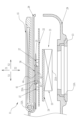
- FIG. 2 is a cross-sectional view of a main part of the imaging device.
- FIG. 5A and 5B are explanatory diagrams illustrating a state of a first heat conducting member sandwiched between a heat source member and a second metal member before and after deformation; 4 is a perspective view showing the positional relationship between a first thermal conductive member, a first metal member, and a second metal member.
- digital camera 10 comprises a camera body 11 and an interchangeable lens barrel 12.
- a lens mount 13 and a release switch 14 are provided on the front of camera body 11.
- Lens mount 13 has a circular imaging opening 13A.
- Lens barrel 12 is removably attached to lens mount 13.
- Digital camera 10 is an example of an imaging device having a heat dissipation structure according to the present invention.
- the camera body 11 is provided with a display 15, operation buttons 16, etc. on the rear side.
- the display 15 is an LCD (Liquid Crystal Display) or an OELD (Organic Electroluminescent Display), etc.
- the display 15 is used to display live view images, captured images, and setting menus, etc.
- the camera body 11 also has a grip portion 11A.
- the camera body 11 has an imaging element unit 21 and a main board 22 built in.
- the main board 22 corresponds to the first electronic component in the claims.
- the imaging element unit 21 includes an imaging element 23 and an imaging element board 24.
- the imaging element 23 is mounted on the imaging element board 24.
- the imaging element unit 21 also includes an anti-vibration device for correcting blurring of the subject light caused by vibrations applied to the camera body 11, and a flexible printed circuit board used for connection to the main board 22, but these are not shown.
- the imaging element unit 21 is attached to the front case 29, for example, by fastening with a screw member (not shown).
- the imaging element 23 is, for example, a CMOS (Complementary Metal Oxide Semiconductor) image sensor, a CCD (Charge Coupled Device) image sensor, or an organic thin-film imaging element.
- the imaging element 23 has a rectangular imaging surface 23A that captures an image of a subject.
- the imaging surface 23A receives subject light that indicates the subject.
- the imaging surface 23A has a two-dimensional array of pixels that photoelectrically convert the received subject light to output an electrical signal.
- the entire imaging surface 23A is exposed to the outside through the imaging opening 13A.
- the imaging element unit 21 and the main board 22 are connected using a flexible printed circuit board (not shown).
- the lens barrel 12 includes a lens barrel body 31 and an imaging optical system 32 (see FIG. 1).
- the lens barrel body 31 is cylindrical in shape and holds the imaging optical system 32 inside, with a lens mount (not shown) and the like provided at the rear end.
- the imaging optical system 32 forms an image of subject light on the imaging element 23.
- the camera body 11 includes, in addition to the image sensor unit 21, the main board 22, and the display 15, a sheet metal member 25, a first heat conductive member 26, a second heat conductive member 27, a rear case 28, and a front case 29.
- the sheet metal member 25 is the first metal member in the claims
- the rear case 28 is the second metal member in the claims.
- the rear case 28 and the front case 29 are combined with a top case, a bottom case, and a cover member (not shown), etc., to form the exterior case of the camera body 11.
- the rear case 28 and the front case 29 house the image sensor unit 21, the main board 22, the sheet metal member 25, the first heat conductive member 26, and the second heat conductive member 27 inside.
- the main board 22 is provided with a laminate 41 as a heat source member. This allows heat from the laminate 41 to be transferred to the main board 22.
- the laminate 41 includes an LSI (Large Scale Integration) 42.
- the laminate 41 includes an LSI 42, an intermediate board 43, and a semiconductor memory 44, with the LSI 42 stacked on one side of the intermediate board 43 and the semiconductor memory 44 stacked on the other side.
- the LSI 42 functions as a CPU (Central Processing Unit) that executes software (programs) and performs various processes.
- the LSI 42 controls the operation of each part of the digital camera 10, including the image sensor 23.
- DRAM dynamic random access memory
- the semiconductor memory 44 is electrically connected to the LSI 42 and is used, for example, as a main memory device in which programs are stored when the LSI 42 is operating.
- the stack 41 is disposed in the Z1 direction (first direction) relative to the imaging element 23.
- the side of the stack 41 where the LSI 42 is located is fixed to the main board 22, and the side where the semiconductor memory 44 is located is located on the Z1 direction side relative to the LSI 42.
- the direction of the imaging surface 23A side of the imaging element 23 is the Z2 direction, and the Z1 direction is the direction opposite to the Z2 direction with respect to the imaging element 23.
- the main board 22 is disposed on the Z1 direction side of the imaging element unit 21 including the imaging element 23, and the laminate 41 is further provided on the Z1 direction side of the main board 22.
- the Y1 and Y2 directions are directions perpendicular to the Z1 and Z2 directions, and in this embodiment, are parallel to the top-bottom direction (up-down direction) of the digital camera 10.
- the X1 and X2 directions are directions perpendicular to the Z1 and Z2 directions and the Y1 and Y2 directions, and in this embodiment, are the left-right direction of the digital camera 10.
- orthogonal includes the meaning of completely orthogonal, as well as the meaning of approximately orthogonal, including tolerances allowed in design and manufacturing.
- parallel includes the meaning of completely parallel, as well as the meaning of approximately parallel, including tolerances allowed in design and manufacturing.
- the sheet metal member 25 is located on the Z1 direction side with respect to the main board 22. At least a portion of the sheet metal member 25 is made of metal, and the entirety of the sheet metal member 25 may be made of metal. In this embodiment, the entire sheet metal member 25 is made of metal and is formed in a plate shape. Examples of metals that are the material of the sheet metal member 25 include aluminum. Note that a material with high thermal conductivity is preferable for the sheet metal member 25, and materials other than aluminum that contain copper may be used as long as a high specific gravity is acceptable.
- the sheet metal member 25 has a rectangular through hole 25A formed therein. The through hole 25A is formed at a position that matches the stack 41.
- the rear case 28 is located on the Z1 direction side of the sheet metal member 25. At least a portion of the rear case 28 is made of metal, and the entire case may be made of metal. In this embodiment, the entire rear case 28 is made of metal, and has a larger area and volume when viewed from a direction parallel to the Z1 direction than the sheet metal member 25. Metals that are the material for the rear case 28 include magnesium, for example. The area ratio of the sheet metal member 25 to the rear case 28 when viewed from a direction parallel to the Z1 direction is, for example, 20%.
- the first thermal conductivity which is the thermal conductivity of the sheet metal member 25 is greater than the second thermal conductivity, which is the thermal conductivity of the rear case 28.
- An example of such a thermal conductivity relationship is when the metal material of the sheet metal member 25 contains aluminum and the metal material of the rear case 28 contains magnesium, as described above. Note that the first thermal conductivity and the second thermal conductivity referred to here are the thermal conductivity of the metal material of the sheet metal member 25 and the rear case 28.
- the first heat conducting member 26 is disposed at a position where it contacts the laminate 41.
- the first heat conducting member 26 contacts the rear case 28 through the through hole 25A.
- the first heat conducting member 26 contacts the sheet metal member 25 by changing its shape. Specifically, as described below, the first heat conducting member 26 contacts the sheet metal member 25 by elastically deforming as a shape change.
- the first heat conducting member 26 and the second heat conducting member 27 are gel-like members that thermally conduct heat generated in a heat source member (a member that generates heat such as the laminate 41) to a heat dissipation member (a member with a large volume such as the rear case 28 and the sheet metal member 25), and use, for example, TIM (Thermal Interface Material).
- the second heat conductive member 27 is arranged in contact with the main board 22.
- two second heat conductive members 27 are provided.
- the number of second heat conductive members 27 may be one, or three or more.
- the two second heat conductive members 27 are arranged around the through hole 25A and are in contact with the sheet metal member 25.
- the two second heat conductive members 27 are arranged at different positions in the X1 and X2 directions, with the through hole 25A between them. In the digital camera 10, there is ample space in the X1 and X2 directions due to the component layout, so it is easy to arrange the second heat conductive members 27 at different positions in the X1 and X2 directions.
- the dimensions of the first heat conduction member 26 in the X1, X2 directions and/or the Y1, Y2 directions are smaller than the dimensions of the through hole 25A in the X1, X2 directions and/or the Y1, Y2 directions, so the first heat conduction member 26 does not come into contact with the sheet metal member 25.
- dimension L11 is the dimension of the first heat conduction member 26 in the X1, X2 directions
- dimension L12 is the dimension of the through hole 25A in the X1, X2 directions. In the state shown in FIG. 6(A), dimension L11 of the first heat conduction member 26 is smaller than dimension L12 of the through hole 25A.
- the sheet metal member 25 is fixed to the rear case 28 by fitting or fastening, and the main board 22 is further attached to the rear case 28 by fastening.
- the first heat conductive member 26 is sandwiched between the laminate 41 and the rear case 28 through the through hole 25A.
- the first heat conductive member 26 passes through the through hole 25A and is sandwiched between the laminate 41 and the rear case 28, and elastically deforms. Specifically, the first heat conductive member 26 is compressed in the Z1 and Z2 directions. When the elastic first heat conductive member 26 is compressed in the Z1 and Z2 directions, it is simultaneously expanded in the X1, X2 and/or Y1, Y2 directions.
- the dimensions of the first heat conductive member 26 in the X1, X2 and/or Y1, Y2 directions are equal to or larger than the dimensions of the through hole 25A in the X1, X2 and/or Y1, Y2 directions, and it comes into contact with the sheet metal member 25.
- the dimension L11 of the first heat conducting member 26 is equal to the dimension L12 of the through hole 25A, and both ends of the first heat conducting member 26 are in contact with the through hole 25A.
- the display 15 is attached to the rear case 28.
- the display 15 is rotatably connected to the rear case 28 via a rotation shaft 15A.
- the display 15 is disposed on the Z1 side of the rear case 28.
- the first heat conductive member 26 is disposed within the range of the display 15.
- the range of the display 15 refers to the range when the display 15 is viewed through in the Z1 direction.
- At least a portion of the through hole 25A is disposed within the range of the display 15. In this embodiment, the entire through hole 25A is disposed within the range of the display 15.
- the thickness of the rear case 28 at portion 28A (see FIG. 6A) in contact with the first heat conductive member 26 is greater than the thickness of portion 28B (see FIG. 6A) not in contact with the first heat conductive member 26.
- the thickness here refers to the dimensions of the rear case 28 in the Z1 and Z2 directions.
- the metal constituting the rear case 28 has a higher thermal conductivity than the first heat conductive member 26.
- the thickness of portion 28A in contact with the first heat conductive member 26 is, for example, 1.2 mm
- the thickness of portion 28B not in contact with the first heat conductive member 26 is, for example, 0.8 mm.
- the operation of the digital camera 10 of this embodiment will be described.
- the digital camera 10 that is, when various operations such as photographing and recording are performed, heat is generated in the laminate 41, which includes the LSI 42 that functions as a CPU, the semiconductor memory 44 that functions as a main storage device, and the intermediate board 43 on which these are stacked.
- the first thermal conductive member 26 is disposed in a position where it contacts the laminate 41, and contacts the rear case 28 through the through hole 25A of the sheet metal member 25. This allows the digital camera 10 to have a small dimension in the thickness direction, and to reliably dissipate heat generated in the laminate 41.
- the thermally conductive member were to come into surface-to-surface contact with the sheet metal member without passing through a through hole, the dimension in the thickness direction of the imaging device would increase by the thickness of the sheet metal member and the thickness of the thermally conductive member.
- the first thermally conductive member 26 passes through the through hole 25A, making it possible to reduce the dimension in the thickness direction and achieve a more compact size, and it is possible to reliably conduct heat generated in the laminate 41 to the rear case 28.
- the second heat conductive member 27 is in contact with the main board 22, is disposed around the through hole 25A, and is in contact with the sheet metal member 25. This allows the second heat conductive member 27 to transfer heat from the stack 41 from the main board 22 and conduct it to the sheet metal member 25. In this way, the heat of the stack 41 is thermally conducted by the sheet metal member 25, so that the heat generated in the stack 41 can be dissipated more reliably. Furthermore, because the sheet metal member 25 and the rear case 28 contain metal, heat is also transferred from the sheet metal member 25 to the rear case 28.
- the thickness of the portion 28A of the rear case 28 that contacts the first heat conducting member 26 is greater than the thickness of the portion 28B that does not contact the first heat conducting member 26, and the metal that constitutes the rear case 28 has a higher thermal conductivity than the first heat conducting member 26.
- the contact between the thick portion 28A of the rear case 28 and the first heat conducting member 26 makes it easier for heat to be conducted. Therefore, the heat generated in the laminate 41 can be dissipated more reliably.
- the display 15 is disposed on the Z1 side relative to the rear case 28, and the first heat conductive member 26 is disposed within the range of the display 15. This allows the heat generated in the laminate 41 to be transferred to the first heat conductive member 26, the rear case 28, and the display 15, so that the heat generated in the laminate 41 can be dissipated more reliably.
- the sheet metal member 25 is entirely made of metal, but it is preferable that the contact surface of the sheet metal member 25 that comes into contact with the first heat conductive member 26 by compression, i.e., at least a part of the inner surface of the through hole 25A, is made of metal. This provides the same effect as the above embodiment, i.e., the heat generated in the laminate 41 can be reliably dissipated. It is also preferable that at least a part of the contact surface of the sheet metal member 25 that comes into contact with the second heat conductive member 27 is made of metal.
- the surface of the sheet metal member 25 that faces the rear case 28 is made of metal
- the first thermal conductivity and the second thermal conductivity described above are the respective thermal conductivity of the surfaces of the sheet metal member 25 and the rear case 28 that face each other.
- the parts other than the metal may be, for example, parts containing a resin material.
- the sheet metal member 25 is made of a material containing aluminum
- at least a portion of the surface of the sheet metal member 25 that faces the rear case 28 is made of a material containing aluminum.
- at least a portion of the surface of the rear case 28 that faces the sheet metal member 25 is made of a material containing magnesium.
- the multiple second heat conduction members 27 are arranged at different positions in the X1 and X2 directions (left and right directions), but this is not limited thereto, and they may be arranged at different positions in the Y1 and Y2 directions (top and bottom directions).
- an LSI 42 has been exemplified as a processor that controls the operation of the camera body, but a processor as a hardware structure of a processing unit that executes various processes such as an LSI 42 is not limited to this.
- Various processors include, instead of or in addition to a CPU, a GPU (Graphical Processing Unit), a Programmable Logic Device (PLD) such as an FPGA (Field Programmable Gate Array) that is a processor whose circuit configuration can be changed after manufacture, and a dedicated electrical circuit that is a processor with a circuit configuration specially designed to execute various processes.
- PLD Programmable Logic Device
- FPGA Field Programmable Gate Array
- a single processing unit may be configured with one of these various processors, or may be configured with a combination of two or more processors of the same or different types (for example, multiple FPGAs, a combination of a CPU and an FPGA, or a combination of a CPU and a GPU, etc.). Multiple processing units may also be configured with one processor.
- multiple processing units may also be configured with one processor.
- first there is a form in which one processor is configured with a combination of one or more CPUs and software, as represented by computers such as clients and servers, and this processor functions as multiple processing units.
- a processor is used that realizes the functions of the entire system including multiple processing units with a single IC (Integrated Circuit) chip, as represented by System On Chip (SoC).
- SoC System On Chip
- the heat source member is not limited to the laminate 41 illustrated in the above embodiment, but may be a single LSI without semiconductor memory or intermediate substrate, or may be any of the various processors described above.
- the hardware structure of these various processors is an electrical circuit that combines circuit elements such as semiconductor elements.
- the present invention can also be applied to imaging devices such as smartphones and video cameras.
Landscapes
- Engineering & Computer Science (AREA)
- Physics & Mathematics (AREA)
- Multimedia (AREA)
- Signal Processing (AREA)
- General Physics & Mathematics (AREA)
- Aviation & Aerospace Engineering (AREA)
- Electromagnetism (AREA)
- Studio Devices (AREA)
- Camera Bodies And Camera Details Or Accessories (AREA)
- Cooling Or The Like Of Electrical Apparatus (AREA)
- Chemical & Material Sciences (AREA)
- Materials Engineering (AREA)
Priority Applications (2)
| Application Number | Priority Date | Filing Date | Title |
|---|---|---|---|
| JP2024549356A JPWO2024071013A1 (https=) | 2022-09-27 | 2023-09-25 | |
| US19/091,729 US20250254408A1 (en) | 2022-09-27 | 2025-03-26 | Heat radiation structure |
Applications Claiming Priority (2)
| Application Number | Priority Date | Filing Date | Title |
|---|---|---|---|
| JP2022154094 | 2022-09-27 | ||
| JP2022-154094 | 2022-09-27 |
Related Child Applications (1)
| Application Number | Title | Priority Date | Filing Date |
|---|---|---|---|
| US19/091,729 Continuation US20250254408A1 (en) | 2022-09-27 | 2025-03-26 | Heat radiation structure |
Publications (1)
| Publication Number | Publication Date |
|---|---|
| WO2024071013A1 true WO2024071013A1 (ja) | 2024-04-04 |
Family
ID=90477821
Family Applications (1)
| Application Number | Title | Priority Date | Filing Date |
|---|---|---|---|
| PCT/JP2023/034657 Ceased WO2024071013A1 (ja) | 2022-09-27 | 2023-09-25 | 放熱構造 |
Country Status (3)
| Country | Link |
|---|---|
| US (1) | US20250254408A1 (https=) |
| JP (1) | JPWO2024071013A1 (https=) |
| WO (1) | WO2024071013A1 (https=) |
Citations (4)
| Publication number | Priority date | Publication date | Assignee | Title |
|---|---|---|---|---|
| JP5225171B2 (ja) * | 2009-03-27 | 2013-07-03 | キヤノン株式会社 | 撮像装置 |
| CN206947326U (zh) * | 2017-06-09 | 2018-01-30 | 深圳市凯木金科技有限公司 | 一种用于pcb板的散热结构 |
| CN209590500U (zh) * | 2019-03-29 | 2019-11-05 | 歌尔科技有限公司 | 摄像头散热模组及头戴设备 |
| WO2021182344A1 (ja) * | 2020-03-13 | 2021-09-16 | 富士フイルム株式会社 | カメラ、カメラボディ及び放熱器 |
-
2023
- 2023-09-25 JP JP2024549356A patent/JPWO2024071013A1/ja active Pending
- 2023-09-25 WO PCT/JP2023/034657 patent/WO2024071013A1/ja not_active Ceased
-
2025
- 2025-03-26 US US19/091,729 patent/US20250254408A1/en active Pending
Patent Citations (4)
| Publication number | Priority date | Publication date | Assignee | Title |
|---|---|---|---|---|
| JP5225171B2 (ja) * | 2009-03-27 | 2013-07-03 | キヤノン株式会社 | 撮像装置 |
| CN206947326U (zh) * | 2017-06-09 | 2018-01-30 | 深圳市凯木金科技有限公司 | 一种用于pcb板的散热结构 |
| CN209590500U (zh) * | 2019-03-29 | 2019-11-05 | 歌尔科技有限公司 | 摄像头散热模组及头戴设备 |
| WO2021182344A1 (ja) * | 2020-03-13 | 2021-09-16 | 富士フイルム株式会社 | カメラ、カメラボディ及び放熱器 |
Also Published As
| Publication number | Publication date |
|---|---|
| US20250254408A1 (en) | 2025-08-07 |
| JPWO2024071013A1 (https=) | 2024-04-04 |
Similar Documents
| Publication | Publication Date | Title |
|---|---|---|
| JP6721745B2 (ja) | 撮像装置および車両 | |
| JP7329757B2 (ja) | 撮像装置、および撮像装置に対して取り付け可能な外付け冷却ユニット | |
| JP5740567B2 (ja) | 撮像ユニットの放熱構造 | |
| EP3599493B1 (en) | Imaging apparatus | |
| JP4872091B2 (ja) | 撮像装置 | |
| US10250785B2 (en) | Electronic apparatus capable of efficient and uniform heat dissipation | |
| JP2008219704A (ja) | 半導体装置 | |
| JP2025031821A (ja) | 撮像装置 | |
| TWM506992U (zh) | 工業用相機之組裝結構 | |
| TWI574561B (zh) | 具有高效率熱傳遞之成像設備及其相關系統 | |
| JPWO2013150621A1 (ja) | 撮像装置 | |
| JP6673584B2 (ja) | 撮像装置 | |
| WO2024071013A1 (ja) | 放熱構造 | |
| US20200351422A1 (en) | Imager and imaging device | |
| JP7503926B2 (ja) | 撮像装置 | |
| JP2010239581A (ja) | 撮像装置 | |
| JP2007134811A (ja) | 撮像装置 | |
| JP2018067901A (ja) | 電子機器 | |
| CN224178227U (zh) | 摄像装置 | |
| JP5427076B2 (ja) | 3ccd小型カメラの放熱構造 | |
| TWI845119B (zh) | 攝像裝置 | |
| JP2011146856A (ja) | 撮像装置 | |
| JP5776197B2 (ja) | 撮像装置 | |
| TWM669265U (zh) | 攝像裝置 | |
| KR20250107006A (ko) | 산업용 카메라 |
Legal Events
| Date | Code | Title | Description |
|---|---|---|---|
| 121 | Ep: the epo has been informed by wipo that ep was designated in this application |
Ref document number: 23869315 Country of ref document: EP Kind code of ref document: A1 |
|
| WWE | Wipo information: entry into national phase |
Ref document number: 2024549356 Country of ref document: JP |
|
| NENP | Non-entry into the national phase |
Ref country code: DE |
|
| 122 | Ep: pct application non-entry in european phase |
Ref document number: 23869315 Country of ref document: EP Kind code of ref document: A1 |