WO2024070604A1 - 固体電解コンデンサ及び製造方法 - Google Patents
固体電解コンデンサ及び製造方法 Download PDFInfo
- Publication number
- WO2024070604A1 WO2024070604A1 PCT/JP2023/032913 JP2023032913W WO2024070604A1 WO 2024070604 A1 WO2024070604 A1 WO 2024070604A1 JP 2023032913 W JP2023032913 W JP 2023032913W WO 2024070604 A1 WO2024070604 A1 WO 2024070604A1
- Authority
- WO
- WIPO (PCT)
- Prior art keywords
- conductive polymer
- wound body
- solid electrolytic
- electrolytic capacitor
- acid
- Prior art date
- Legal status (The legal status is an assumption and is not a legal conclusion. Google has not performed a legal analysis and makes no representation as to the accuracy of the status listed.)
- Ceased
Links
Images


Classifications
-
- H—ELECTRICITY
- H01—ELECTRIC ELEMENTS
- H01G—CAPACITORS; CAPACITORS, RECTIFIERS, DETECTORS, SWITCHING DEVICES, LIGHT-SENSITIVE OR TEMPERATURE-SENSITIVE DEVICES OF THE ELECTROLYTIC TYPE
- H01G9/00—Electrolytic capacitors, rectifiers, detectors, switching devices, light-sensitive or temperature-sensitive devices; Processes of their manufacture
- H01G9/004—Details
- H01G9/02—Diaphragms; Separators
-
- H—ELECTRICITY
- H01—ELECTRIC ELEMENTS
- H01G—CAPACITORS; CAPACITORS, RECTIFIERS, DETECTORS, SWITCHING DEVICES, LIGHT-SENSITIVE OR TEMPERATURE-SENSITIVE DEVICES OF THE ELECTROLYTIC TYPE
- H01G9/00—Electrolytic capacitors, rectifiers, detectors, switching devices, light-sensitive or temperature-sensitive devices; Processes of their manufacture
- H01G9/004—Details
- H01G9/022—Electrolytes; Absorbents
- H01G9/025—Solid electrolytes
- H01G9/028—Organic semiconducting electrolytes, e.g. TCNQ
-
- H—ELECTRICITY
- H01—ELECTRIC ELEMENTS
- H01G—CAPACITORS; CAPACITORS, RECTIFIERS, DETECTORS, SWITCHING DEVICES, LIGHT-SENSITIVE OR TEMPERATURE-SENSITIVE DEVICES OF THE ELECTROLYTIC TYPE
- H01G9/00—Electrolytic capacitors, rectifiers, detectors, switching devices, light-sensitive or temperature-sensitive devices; Processes of their manufacture
- H01G9/145—Liquid electrolytic capacitors
-
- H—ELECTRICITY
- H01—ELECTRIC ELEMENTS
- H01G—CAPACITORS; CAPACITORS, RECTIFIERS, DETECTORS, SWITCHING DEVICES, LIGHT-SENSITIVE OR TEMPERATURE-SENSITIVE DEVICES OF THE ELECTROLYTIC TYPE
- H01G9/00—Electrolytic capacitors, rectifiers, detectors, switching devices, light-sensitive or temperature-sensitive devices; Processes of their manufacture
- H01G9/15—Solid electrolytic capacitors
Definitions
- the present invention relates to a wound solid electrolytic capacitor that contains a conductive polymer as an electrolyte and a manufacturing method.
- An electrolytic capacitor has valve metals such as tantalum or aluminum as anode and cathode foils.
- the anode foil is enlarged by forming the valve metal into a sintered or etched foil, etc., and has a dielectric coating layer on the enlarged surface.
- An electrolyte is interposed between the anode foil and the cathode foil. The electrolyte is in close contact with the uneven surface of the anode foil and functions as a true cathode.
- a wound type electrolytic capacitor has a wound body consisting of an anode foil, a cathode foil, and a separator.
- the anode foil and the cathode foil are strip-shaped foil bodies.
- the cathode foil and the anode foil are placed opposite each other via the separator.
- the strip is then wound so that the short side of the strip coincides with the winding axis and the long side of the strip is curved.
- a strip-shaped adhesive tape is wound around the outer circumference of the wound body to prevent the wound body from unwinding (see Patent Document 1, for example).
- Conductive polymers are derived from monomers with ⁇ -conjugated double bonds.
- An example of a conductive polymer is poly(3,4-ethylenedioxythiophene) (PEDOT), which has excellent adhesion to dielectric films.
- PEDOT poly(3,4-ethylenedioxythiophene)
- Polyanions such as organic sulfonic acids are used as dopants during chemical oxidative polymerization or electrolytic oxidative polymerization of conductive polymers, resulting in high conductivity.
- solid electrolytic capacitors In addition to having a low equivalent series resistance, solid electrolytic capacitors have the advantage of being long-lived, as there is no risk of the electrolyte drying up due to evaporation to the outside over time.
- so-called hybrid-type solid electrolytic capacitors that use a conductive polymer and an electrolyte in combination to repair defects in the dielectric film and reduce leakage current in solid electrolytic capacitors are also becoming popular (see, for example, Patent Document 2).
- the conductive polymer is attached to the inside of the wound body by immersing the wound body in a conductive polymer liquid.
- the conductive polymer liquid is a dispersion or solution prepared by dispersing or dissolving a conductive polymer in water, with water being the main solvent.
- the method of impregnating the wound body with a conductive polymer liquid does not expose the wound body to high heat and does not leave impurities on the wound body.
- the adhesive tape used to secure the outer circumference of the wound body has a hydrophobic base material such as polypropylene, because water is often used in the manufacturing process of solid electrolytic capacitors.
- the hydrophobic adhesive tape repels the conductive polymer liquid, preventing it from penetrating into the inside of the wound body. Therefore, there is room for improving the adhesion between the conductive polymer and the dielectric film further, and improving characteristics such as increasing the capacitance of the solid electrolytic capacitor.
- the present invention has been proposed to solve the above problems, and its purpose is to provide a manufacturing method that increases the capacitance appearance rate of solid electrolytic capacitors, and a solid electrolytic capacitor with an increased capacitance appearance rate.
- the method for manufacturing a solid electrolytic capacitor of this embodiment includes a winding step in which an anode foil and a cathode foil, each having a dielectric film formed thereon, are wound facing each other to form a wound body, a winding stop step in which the circumferential surface of the wound body is wound with a hydrophobic adhesive tape, and a solid electrolyte formation step in which the wound body wound with the adhesive tape is immersed in a conductive polymer liquid in which a conductive polymer is dispersed or dissolved, thereby adhering the conductive polymer to the inside of the wound body.
- the wound body is immersed in the conductive polymer liquid having a viscosity of 10 mPa ⁇ s or more and 60 mPa ⁇ s or less.
- the solid electrolytic capacitor of this embodiment includes a wound body in which an anode foil and a cathode foil, each having a dielectric film formed thereon, are wound facing each other, a hydrophobic adhesive tape that secures the circumferential surface of the wound body, and a conductive polymer that adheres to at least the dielectric film, and the conductive polymer is formed using a conductive polymer liquid in which the conductive polymer is dispersed or dissolved and has a viscosity of 10 mPa ⁇ s to 60 mPa ⁇ s.
- the conductive polymer may be attached by impregnating the wound body with the conductive polymer liquid.
- the conductive polymer liquid may contain water as a solvent.
- the conductive polymer liquid may further contain a high boiling point solvent.
- the method may further include an electrolyte impregnation step of impregnating the wound body with an electrolyte.
- the method may further include an electrolyte impregnated into the wound body.
- a separator having an air resistance of 5.5 [s/100 mL] or less may be interposed between the anode foil and the cathode foil and wound.
- a separator having an air resistance of 5.5 [s/100 mL] or less may be interposed between the anode foil and the cathode foil within the winding body.
- the anode foil and the cathode foil are connected to a lead terminal having a flat portion, a round bar portion, and a lead wire in series at the flat portion, and the round bar portion protrudes from one end face of the wound body, and the lead wire is drawn out.
- the wound body may be immersed in the conductive polymer liquid to a height at least equal to or higher than the height of one end face of the wound body.
- the flat portion, the round bar portion, and the lead wire are connected in series, the flat portion is connected to the anode foil and the cathode foil, the round bar portion protrudes from one end face of the winding, the lead wire is connected to a lead terminal, and the conductive polymer may be attached to a height equal to or higher than the height of the one end face of the winding.
- the present invention increases the capacitance appearance rate of solid electrolytic capacitors.
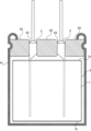
- FIG. 1 is a schematic diagram of a solid electrolytic capacitor according to an embodiment of the present invention.
- 2 is a schematic diagram showing a state in which a lead terminal and an electrode foil of the solid electrolytic capacitor according to the embodiment are connected to each other.
- FIG. 3A and 3B are schematic diagrams showing the liquid level position of a conductive polymer liquid or the adhesion position of a conductive polymer.
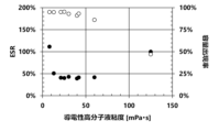
- 1 is a graph showing the relationship between the ESR and the capacitance appearance rate and the viscosity of a conductive polymer liquid.
- 1 is a graph showing the relationship between the height of the immersion liquid surface of the conductive polymer liquid and the amount of the conductive polymer adhered.
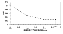
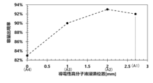
- FIG. 1 is a graph showing the relationship between the height of the immersion liquid surface of a conductive polymer liquid and tan ⁇ of a solid electrolytic capacitor. 1 is a graph showing the relationship between the height of the immersion liquid surface of the conductive polymer liquid and the capacitance appearance rate of the solid electrolytic capacitor.
- FIG. 11 is a scatter diagram showing the relationship between the ESR and the capacitance appearance rate versus the viscosity of a conductive polymer liquid.
- a solid electrolytic capacitor is a passive device that obtains capacitance through the dielectric polarization of a dielectric film and stores and discharges electric charge.
- This solid electrolytic capacitor includes an anode foil and a cathode foil on whose surface a dielectric film is formed. The anode foil and the cathode foil are arranged opposite each other.
- a separator is interposed between the anode foil and the cathode foil to prevent the anode foil and the cathode foil from shorting out.
- a conductive polymer is attached to the dielectric film of the anode foil.
- the conductive polymer is the electrolyte of the solid electrolytic capacitor, and is arranged in a line between the dielectric film and the cathode body to create a conductive path, making it the true cathode.
- a liquid electrolyte can also be used in solid electrolytic capacitors. The electrolyte fills the gap between the dielectric film and the conductive polymer.
- FIG. 1 is a schematic diagram of a wound body provided in a solid electrolytic capacitor.
- a solid electrolytic capacitor is of a wound type. That is, the solid electrolytic capacitor is provided with a wound body 1.
- the wound body 1 is formed by winding a laminate of an anode foil, a cathode foil, and a separator in a spiral shape multiple times, and has a cylindrical shape.
- the anode foil and the cathode foil are strip-shaped foil bodies. The short side of the strip is aligned with the central axis of the wound body 1, and the strip is wound so that the long side is rounded.
- the process of winding the anode foil, the cathode foil, and the separator to form the wound body 1 is called the winding process.
- each of the anode foil and cathode foil Prior to the winding process, each of the anode foil and cathode foil is connected to a lead terminal 3.
- the lead terminal 3 is electrically and mechanically connected to the anode foil and cathode foil by cold welding, ultrasonic welding, laser welding, or the like.
- the lead terminal 3 protrudes from one of the lead-out end faces 1a of the winding body 1 and is an electrical conductor that electrically connects the solid electrolytic capacitor to the mounting board.
- a strip of adhesive tape 2 is wound around the outer circumference of the wound body 1. At least the outer end of the strip of adhesive tape 2 is secured to prevent the wound body 1 from unraveling.
- the process of securing the outer surface of the wound body 1 with adhesive tape 2 is called the winding securing process.
- the adhesive tape 2 has a hydrophobic base material such as polypropylene to provide resistance to moisture during the manufacturing process of the solid electrolytic capacitor. An adhesive layer is laminated on this hydrophobic base material, and the adhesive tape 2 is hydrophobic.
- the width of this adhesive tape 2 in the short direction of the band is the same or approximately the same as the axial length of the roll 1.
- the adhesive tape 2 is wound around the roll 1 so as to cover at least the outer end of the band of the roll 1.
- the adhesive tape 2 is also wound around the roll 1 so that the edges of the adhesive tape 2 in the long direction of the band are flush or approximately flush with the lead-out end face 1a and the opposite end face 1b of the roll 1.
- the process moves to the solid electrolyte formation process.
- a conductive polymer is attached to the inside of the wound body 1.
- the conductive polymer covers at least a part of the dielectric film.
- the conductive polymer is formed in the wound body 1 using a conductive polymer liquid.
- the conductive polymer liquid is a dispersion or solution in which a conductive polymer is dispersed or dissolved.
- the main solvent of the conductive polymer liquid is water, in which conductive polymer powder or particles are dispersed or dissolved.
- the wound body 1 is immersed in the conductive polymer liquid, and the wound body 1 is impregnated with the conductive polymer liquid.
- the wound body 1 may be immersed in the conductive polymer liquid once or multiple times.
- the wound body 1 may be impregnated with the conductive polymer liquid in a reduced pressure environment.
- the solvent in the conductive polymer liquid is removed by drying.
- the temperature environment is, for example, 40°C or higher and 200°C or lower, and the drying time is, for example, in the range of 3 minutes or higher and 180 minutes or lower.
- the drying process may be repeated multiple times. Drying may be performed in a reduced pressure environment, for example, by reducing the pressure to 5 kPa or higher and 100 kPa or lower.
- the solid electrolyte formation process is followed by an impregnation process in which the electrolyte is impregnated.
- the wound body 1 with the conductive polymer attached is impregnated with the electrolyte once or multiple times in an atmospheric pressure environment or a reduced pressure environment.
- the wound body 1 filled with the conductive polymer or both the conductive polymer and the electrolyte, i.e., the capacitor element is inserted into a cylindrical exterior case 41 with a bottom and sealed with a sealing member 42.
- the sealing member 42 is an elastic body for sealing the capacitor element within the exterior case, and has an insertion hole 43 through which the lead terminal 3 passes. The lead terminal 3 is pressed into the insertion hole 43 and pulled out from the sealing member 42.
- the manufacture of the solid electrolytic capacitor is completed after an aging process. In the aging process, a DC voltage is applied to the solid electrolytic capacitor to repair defects in the dielectric film layer, etc.
- the capacitor element may be covered with a laminate film instead of an exterior case.
- the capacitor element may also be molded with a resin such as a heat-resistant resin or an insulating resin.
- the capacitor element may be sealed by forming the resin into a thin film using a method such as dip coating or printing.
- the anode foil is a long foil made of a valve metal, such as aluminum, tantalum, niobium, niobium oxide, titanium, hafnium, zirconium, zinc, tungsten, bismuth, and antimony.
- the cathode foil is a long foil made of the same valve metal as the anode foil or other metals, such as silver.
- the cathode foil may be a layered foil having a carbon layer laminated on a silver layer.
- the purity of the anode foil is preferably 99.9% or more, and that of the cathode foil is preferably 99% or more, but may contain silicon, iron, copper, magnesium, zinc, and the like.
- the long foil may be formed by stretching valve metal or the like, or by sintering valve metal powder.
- a surface expansion layer is formed on one or both sides of the anode foil.
- the surface expansion layer is an etching layer formed by etching the foil, a sintered layer formed by sintering valve metal powder, or a deposition layer formed by depositing valve metal particles onto the foil.
- the surface expansion layer has a porous structure, consisting of tunnel-shaped pits, spongy pits, or spaces between densely packed powder or particles.
- Tunnel-shaped etching pits are holes dug in the thickness direction of the foil. These tunnel-shaped etching pits are typically formed by passing a direct current in an acidic aqueous solution, such as hydrochloric acid, in which halogen ions are present. The tunnel-shaped etching pits are further expanded in diameter by passing a direct current in an acidic aqueous solution, such as nitric acid. The spongy etching pits make the expanded surface layer into a sponge-like layer with fine gaps that are connected together in a space. These spongy etching pits are formed by passing an alternating current in an acidic aqueous solution, such as hydrochloric acid, in which halogen ions are present.
- the sintered layer is produced by obtaining a powder of a valve action metal of the same or different type as the foil body by a milling method, atomization method, melt spinning method, rotating disk method, rotating electrode method, etc., forming it into a paste using a binder or solvent, applying it to the foil body, drying it, and heating and sintering it in a vacuum or reducing atmosphere, etc.
- the atomization method may be any of water atomization method, gas atomization method, and water gas atomization method.
- the vapor deposition layer is produced by, for example, resistance heating vapor deposition method or electron beam heating vapor deposition method. This vapor deposition layer is formed by heating and evaporating a valve action metal of the same or different type as the foil body by resistance heat or electron beam energy, and depositing the vapor of the valve action metal particles on the surface of the foil body.
- the dielectric film is formed on the uneven surface of the surface-expanding layer.
- the dielectric film is typically an oxide film formed on the uneven surface of the surface-expanding layer, and if the anode foil is made of aluminum, it is an aluminum oxide layer formed by oxidizing the uneven surface of the surface-expanding layer.
- a voltage is applied to the anode foil in a chemical conversion solution until the desired withstand voltage is achieved.
- the chemical conversion solution is a solution that does not contain halogen ions, and examples of such solutions include phosphoric acid-based chemical conversion solutions such as ammonium dihydrogen phosphate, boric acid-based chemical conversion solutions such as ammonium borate, and adipic acid-based chemical conversion solutions such as ammonium adipate.
- phosphoric acid-based chemical conversion solutions such as ammonium dihydrogen phosphate
- boric acid-based chemical conversion solutions such as ammonium borate
- adipic acid-based chemical conversion solutions such as ammonium adipate.
- a surface enlargement layer may be formed on cathode foil as necessary. Plain foil without a surface enlargement layer may also be used as cathode foil.
- Cathode foil may have a dielectric film formed thereon as with anode foil.
- the dielectric film may be a natural oxide film, or a thin oxide film (approximately 1 to 10 V) formed by chemical conversion treatment. The natural oxide film is formed when the cathode foil reacts with oxygen in the air.
- the cathode foil may have a conductive layer laminated on the foil surface.
- the conductive layer is, for example, a layer containing a metal nitride such as titanium, zirconium, tantalum, or niobium, a metal carbide, a metal carbonitride, or carbon.
- the metal nitride, metal carbide, metal carbonitride, and carbon are formed by a deposition method, a slurry coating method, or the like.
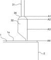
- (Lead terminal) 2 is a schematic diagram of the lead terminal 3.
- the lead terminal 3 is drawn through the sealing member 4, and is configured with a lead wire 31, a round bar portion 32, and a flat portion 33 arranged in a series.
- the sealing member 42 is an elastic body for sealing the capacitor element in an exterior case, and has an insertion hole 43 through which the lead terminal 3 passes.
- the lead wire 31 is an electric wire that extends outside the sealing member 42 and electrically connects the solid electrolytic capacitor to the mounting board.
- This lead wire 31 is generally a copper-coated steel wire called a CP wire, and the surface is solder-plated with lead, tin, or the like.
- the round bar portion 32 is typically made of aluminum and is a generally cylindrical round bar.
- the cross-sectional shape of the round bar portion 32 is not limited to a perfect circle, and may be an ellipse, a polygonal shape such as a triangle or a rectangle, or another shape.
- the lead wire 31 and the round bar portion 32 are connected by arc welding or the like, and a connection portion 34 is interposed between the lead wire 31 and the round bar portion 32 by welding.
- the lead wire 31 may be formed from a part of the round bar portion 32.
- the round bar portion 32 is set to be one size larger than the insertion hole 43 of the sealing member 42. The round bar portion 32 is pressed into the insertion hole 43, and is in close contact with the inner wall of the insertion hole 43 due to the increase in internal pressure of the sealing member 42 after it is crimped.
- the flat portion 33 is formed by crushing the side of the round bar portion 32 opposite the lead wire 31 by pressing or the like into a flat plate shape.
- the boundary between the round bar portion 32 and the flat portion 33 is an inclined portion whose thickness decreases linearly to the thickness of the flat portion 33. This inclined portion is included in the round bar portion 32.
- the flat portion 33 is electrically and mechanically connected to each electrode foil 5, which is a collective term for anode foil and cathode foil, using one of various connection methods such as stitch connection, cold pressure welding, ultrasonic welding, or laser welding.
- the flat portion 33 is brought into contact with one side and one side of the long side of the electrode foil 5, and the round bar portion 32 and the lead wire 31 are allowed to protrude from the electrode foil 5 so as to be perpendicular to the long side of the electrode foil 5, connecting the flat portion 33 and the electrode foil 5.
- the winding process is performed after the lead terminals 3 are connected to each electrode foil 5.
- the separator prevents short-circuiting between the anode foil and the cathode foil, and holds the conductive polymer and the electrolyte.
- the separator may be made of cellulose such as kraft, Manila hemp, esparto, hemp, rayon, or a mixture of these, polyester resins such as polyethylene terephthalate, polybutylene terephthalate, polyethylene naphthalate, or derivatives thereof, polytetrafluoroethylene resins, polyvinylidene fluoride resins, vinylon resins, polyamide resins such as aliphatic polyamides, semi-aromatic polyamides, or fully aromatic polyamides, polyimide resins, polyethylene resins, polypropylene resins, trimethylpentene resins, polyphenylene sulfide resins, acrylic resins, polyvinyl alcohol resins, or the like, which may be used alone or in combination.
- the separator may be fibrillated by generating thin fibers that branch out from the surface of the original fibers, for example, fibrillated cellulose. Fibrillation can be achieved, for example, by beating. The fibrillated fibers are entangled with each other using the fibrillated thin fibers, improving the strength of the separator. This allows the separator to be made thinner.
- a separator with an air resistance of 5.5 [s/100 mL] or less for the wound body 1. If the separator has an air resistance of 5.5 [s/100 mL] or less, the conductive polymer liquid will easily seep into the wound body 1 during the solid electrolyte formation process. This increases the amount of conductive polymer liquid impregnated into the wound body 1 and the amount of conductive polymer attached to the wound body 1, improving the appearance rate of solid electrolytic capacitors.
- the air permeability resistance is also called the Gurley value, and is the time required for 100 mL of air to permeate the separator.
- the air permeability resistance is measured by the Gurley method according to JIS P8117:2009.
- a gasket with an inner diameter of 28.6 mm is used for the measurement.
- a gasket with an inner diameter of 6 mm is used for the measurement, and the value is converted to the value measured with an inner diameter of 28.6 mm.
- a conversion formula is used in which the value obtained with an inner diameter of 6 mm is multiplied by 6 2 /28.6 2 .
- Conductive polymers are self-doped conjugated polymers doped with an intramolecular dopant, or conjugated polymers doped with an external dopant molecule.
- Conjugated polymers are obtained by chemical oxidative polymerization or electrolytic oxidative polymerization of a monomer having a ⁇ -conjugated double bond or a derivative thereof.
- the dopant or external dopant molecule is an acceptor that easily accepts electrons into the conjugated polymer, or a donor that easily gives electrons to the conjugated polymer, which allows the conductive polymer to exhibit high conductivity.
- conjugated polymers can be used without any particular limitations. Examples include polypyrrole, polythiophene, polyfuran, polyaniline, polyacetylene, polyphenylene, polyphenylenevinylene, polyacene, polythiophenevinylene, etc. These conjugated polymers may be used alone, or two or more types may be combined, or they may be copolymers of two or more types of monomers.
- conjugated polymers formed by polymerizing thiophene or its derivatives
- conjugated polymers formed by polymerizing 3,4-ethylenedioxythiophene i.e., 2,3-dihydrothieno[3,4-b][1,4]dioxine
- 3-alkylthiophene 3-alkoxythiophene
- 3-alkyl-4-alkoxythiophene 3,4-alkylthiophene, 3,4-alkoxythiophene, or derivatives thereof.
- thiophene derivative a compound selected from thiophenes having substituents at the 3rd and 4th positions is preferred, and the substituents at the 3rd and 4th positions of the thiophene ring may form a ring together with the carbons at the 3rd and 4th positions.
- the alkyl group or alkoxy group preferably has 1 to 16 carbon atoms.
- a polymer of 3,4-ethylenedioxythiophene called EDOT i.e., poly(3,4-ethylenedioxythiophene) called PEDOT
- a substituent may be added to 3,4-ethylenedioxythiophene.
- an alkylated ethylenedioxythiophene having an alkyl group having 1 to 5 carbon atoms added as a substituent may be used.
- alkylated ethylenedioxythiophene examples include methylated ethylenedioxythiophene (i.e., 2-methyl-2,3-dihydro-thieno[3,4-b][1,4]dioxine), ethylated ethylenedioxythiophene (i.e., 2-ethyl-2,3-dihydro-thieno[3,4-b][1,4]dioxine), butylated ethylenedioxythiophene (i.e., 2-butyl-2,3-dihydro-thieno[3,4-b][1,4]dioxine), and 2-alkyl-3,4-ethylenedioxythiophene.
- methylated ethylenedioxythiophene i.e., 2-methyl-2,3-dihydro-thieno[3,4-b][1,4]dioxine
- ethylated ethylenedioxythiophene i
- dopant can be used without any particular limitation.
- a single dopant may be used, or two or more dopants may be used in combination.
- a polymer or monomer may also be used.
- dopants include inorganic acids such as polyanions, boric acid, nitric acid, and phosphoric acid, and organic acids such as acetic acid, oxalic acid, citric acid, tartaric acid, squaric acid, rhodizonic acid, croconic acid, salicylic acid, p-toluenesulfonic acid, 1,2-dihydroxy-3,5-benzenedisulfonic acid, methanesulfonic acid, trifluoromethanesulfonic acid, borodisalicylic acid, bisoxalateborate acid, sulfonylimide acid, dodecylbenzenesulfonic acid, propylnaphthalenesulfonic acid, and butylnaphthalenesulfonic acid
- Polyanions include, for example, substituted or unsubstituted polyalkylenes, substituted or unsubstituted polyalkenylenes, substituted or unsubstituted polyimides, substituted or unsubstituted polyamides, and substituted or unsubstituted polyesters, and include polymers consisting only of structural units having an anionic group, and polymers consisting of structural units having an anionic group and structural units not having an anionic group.
- polyanions include polyvinyl sulfonic acid, polystyrene sulfonic acid, polyallylsulfonic acid, polyacrylic sulfonic acid, polymethacrylic acid, poly(2-acrylamido-2-methylpropanesulfonic acid), polyisoprene sulfonic acid, polyacrylic acid, polymethacrylic acid, and polymaleic acid.
- PEDOT/PSS poly(3,4-ethylenedioxythiophene) doped with polystyrene sulfonic acid, and hereafter this conductive polymer will be referred to as PEDOT/PSS.
- the wound body 1 is immersed in a conductive polymer liquid to adhere the conductive polymer to the inside of the wound body 1.
- the conductive polymer liquid is a dispersion liquid in which a conductive polymer is dispersed or a solution in which a conductive polymer is dissolved.
- the conductive polymer liquid is prepared by purifying the solution after electrolytic polymerization or chemical polymerization by ultrafiltration, cation exchange, anion exchange, etc., removing residual monomers and impurities, and dispersing or dissolving the conductive polymer in a solvent, or by adding particles or powder of the conductive polymer to a solvent and dispersing or dissolving the conductive polymer in the solvent.
- the main solvent for the conductive polymer liquid is water.
- the viscosity of the conductive polymer liquid is adjusted to 10 mPa ⁇ s or more and 60 mPa ⁇ s or less by, for example, the processing time by a dispersion method such as an ultrasonic homogenizer or jet mixing, the type and amount of the dispersion medium, the type and amount of the additive, the degree of polymerization of the polymer, the polymer concentration, etc. If the viscosity is within this range, the conductive polymer liquid can easily permeate the wound body 1 while maintaining a good ESR of the solid electrolytic capacitor, thereby improving the capacitance appearance rate of the solid electrolytic capacitor. However, if the viscosity is less than 10 mPa ⁇ s, the ESR will increase rapidly. Also, if the viscosity exceeds 60 mPa ⁇ s, the capacitance appearance rate will decrease rapidly.
- the capacitance occurrence rate is the ratio of the capacitance of the solid electrolytic capacitor to the combined capacitance of the anode foil and cathode foil, and is the percentage obtained by dividing the capacitance of the solid electrolytic capacitor by the combined capacitance of the anode foil and cathode foil.
- the combined capacitance of the anode foil and cathode foil is the combined capacitance when the solid electrolytic capacitor is regarded as a capacitor with the anode side and cathode side connected in series.
- the cathode foil has a conductive layer, or if the capacitance of the cathode body can be said to converge to infinity, the combined capacitance of the anode foil and cathode foil is the capacitance of the anode foil.
- the solvent for the conductive polymer dispersion may be a mixture of water and an organic solvent, so long as the conductive polymer particles or powder can be dispersed or dissolved in the solvent.
- organic solvents include polar solvents, alcohols, esters, hydrocarbons, carbonate compounds, ether compounds, chain ethers, heterocyclic compounds, and nitrile compounds.
- Polar solvents include N-methyl-2-pyrrolidone, N,N-dimethylformamide, N,N-dimethylacetamide, dimethylsulfoxide, etc.
- Alcohols include methanol, ethanol, propanol, butanol, etc.
- Esters include ethyl acetate, propyl acetate, butyl acetate, etc.
- Hydrocarbons include hexane, heptane, benzene, toluene, xylene, etc.
- Carbonate compounds include ethylene carbonate, propylene carbonate, etc.
- Ether compounds include dioxane, diethyl ether, etc.
- Chain ethers include ethylene glycol dialkyl ether, propylene glycol dialkyl ether, polyethylene glycol dialkyl ether, polypropylene glycol dialkyl ether, etc.
- Heterocyclic compounds include 3-methyl-2-oxazolidinone, etc.
- Nitrile compounds include acetonitrile, glutarodinitrile, methoxyacetonitrile, propionitrile, benzonitrile, etc.
- the pH of the conductive polymer liquid may be adjusted, and polyhydric alcohols and various additives may be added as necessary.
- pH adjusters include ammonia water, sodium hydroxide, primary amines, secondary amines, and tertiary amines.
- polyhydric alcohols include sorbitol, ethylene glycol, diethylene glycol, triethylene glycol, polyoxyethylene glycol, polyoxypropylene glycol, glycerin, polyglycerin, polyoxyethylene glycerin, xylitol, erythritol, mannitol, dipentaerythritol, pentaerythritol, and combinations of two or more of these.
- Polyhydric alcohols are high-boiling point solvents, and remain in the wound body 1 even after the wound body 1 is impregnated with the conductive polymer liquid and dried.
- the polyhydric alcohols have the effect of reducing the ESR and improving the withstand voltage of the solid electrolytic capacitor.
- additives include organic binders, surfactants, dispersants, defoamers, coupling agents, antioxidants, and ultraviolet absorbers.
- FIG. 3 is a schematic diagram showing the liquid level position of the conductive polymer liquid or the position where the conductive polymer is attached.
- the boundary position between the lead wire 31 of the lead terminal 3 and the upper end of the connection portion 34 is defined as the upper end A1 of the connection portion.
- the boundary position between the lower end of the connection portion 34 of the lead terminal 3 and the round bar portion 32 is defined as the lower end A2 of the connection portion.
- A3 is a position 1 mm or more from the lead end surface 1a of the wound body 1.
- A3 is, for example, a half-height position in the length direction of the round bar portion 32.
- the lead end surface 1a of the wound body 1 is defined as the end surface position A4.
- the liquid level of the conductive polymer liquid is located at least on the lead-out end surface 1a of the wound body 1. It is also preferable to immerse the wound body 1 in the conductive polymer liquid so that the liquid level of the conductive polymer liquid is located between a height position A3 of 1 mm or more from the lead-out end surface 1a of the wound body 1 and the upper end A1 of the connection part, for example, the halfway position A3 of the round bar. In other words, it is preferable to attach the conductive polymer to the lead terminal 3 in the range between at least the position A3 and the upper end A1 of the connection part, in addition to the inside of the wound body 1. Since the contact angle between the hydrophobic adhesive tape and the conductive polymer liquid is large, a meniscus is formed. Therefore, it is necessary to immerse the wound body 1 in the conductive polymer liquid beyond the upper end edge of the hydrophobic adhesive tape 2.
- the conductive polymer liquid is sucked up from the opposite end face 1b and drips down from the outlet end face 1a.
- a separator with an air resistance of 5.5 [s/100 mL] or less, the conductive polymer liquid that enters from the outlet end face 1a and the opposite end face 1b permeates through the separator and into the wound body 1.
- the round bar portion 32 is immersed in the conductive polymer liquid at least to a height equal to or greater than the position A3, and in addition to the wound body 1, the conductive polymer adheres to the round bar portion 32 at least to a height equal to or greater than the position A3, thereby increasing the capacitance appearance rate of the solid electrolytic capacitor and reducing the dielectric loss tangent (tan ⁇ ).
- the time for impregnation with the conductive polymer liquid can be set appropriately depending on the size of the wound body 1. Long periods of impregnation do not adversely affect the properties.
- decompression or pressure treatment may be performed as necessary to promote impregnation.
- the solid electrolyte formation process may be repeated multiple times.
- the solvent of the conductive polymer liquid is evaporated and removed by drying as necessary. Heat drying or reduced pressure drying may be performed as necessary to remove the solvent.
- a repair chemical treatment may be performed to repair defects such as voids, cracks, or scratches in various parts of the dielectric film caused by insufficient formation of the dielectric film and bending stress caused by winding.
- the chemical solution used for the repair chemical conversion is an aqueous solution of phosphoric acid such as ammonium dihydrogen phosphate or diammonium hydrogen phosphate, boric acid such as ammonium borate, or adipic acid such as ammonium adipate dissolved in water.
- the voltage is preferably set to, for example, 0.1 to 1.2 times the chemical conversion voltage.
- the electrolyte is a mixed solution in which a solute is dissolved in a solvent and an additive is added as necessary.
- the electrolyte does not need to dissolve a solute, and may be a solvent only, or may contain a solvent and an additive.
- the solvent for the electrolyte includes a protic organic polar solvent or an aprotic organic polar solvent, which may be used alone or in combination of two or more.
- the solute for the electrolyte includes an anion component and a cation component.
- the solute is typically a salt of an organic acid, a salt of an inorganic acid, or a salt of a complex compound of an organic acid and an inorganic acid, which may be used alone or in combination of two or more.
- An acid that becomes an anion and a base that becomes a cation may be added separately to the solvent.
- Protic organic polar solvents which are solvents, include monohydric alcohols, polyhydric alcohols, and oxyalcohol compounds.
- monohydric alcohols include ethanol, propanol, butanol, pentanol, hexanol, cyclobutanol, cyclopentanol, cyclohexanol, and benzyl alcohol.
- polyhydric alcohols and oxyalcohol compounds examples include ethylene glycol, propylene glycol, glycerin, polyglycerin, methyl cellosolve, ethyl cellosolve, methoxypropylene glycol, dimethoxypropanol, and alkylene oxide adducts of polyhydric alcohols such as polyethylene glycol and polyoxyethylene glycerin.
- polyhydric alcohols are preferable as the solvent, and ethylene glycol and glycerin are particularly preferable.
- Ethylene glycol and glycerin cause a change in the higher-order structure of the conductive polymer, resulting in good initial ESR characteristics and also good high-temperature characteristics. It is even better if the ethylene glycol is 30 wt% or more in the solvent.
- aprotic organic polar solvents include sulfones, amides, lactones, cyclic amides, nitriles, and sulfoxides.
- sulfones include dimethyl sulfone, ethyl methyl sulfone, diethyl sulfone, sulfolane, 3-methyl sulfolane, and 2,4-dimethyl sulfolane.
- amides include N-methylformamide, N,N-dimethylformamide, N-ethylformamide, N,N-diethylformamide, N-methylacetamide, N,N-dimethylacetamide, N-ethylacetamide, N,N-diethylacetamide, and hexamethylphosphoric amide.
- lactones and cyclic amides include ⁇ -butyrolactone, ⁇ -valerolactone, ⁇ -valerolactone, N-methyl-2-pyrrolidone, ethylene carbonate, propylene carbonate, butylene carbonate, and isobutylene carbonate.
- nitriles include acetonitrile, 3-methoxypropionitrile, and glutaronitrile.
- sulfoxides include dimethyl sulfoxide.
- Organic acids that act as anionic solutes include carboxylic acids such as oxalic acid, succinic acid, glutaric acid, pimelic acid, suberic acid, sebacic acid, phthalic acid, isophthalic acid, terephthalic acid, maleic acid, adipic acid, benzoic acid, toluic acid, enanthic acid, malonic acid, 1,6-decanedicarboxylic acid, 1,7-octanedioic acid, azelaic acid, undecanedioic acid, dodecanedioic acid, tridecanedioic acid, t-butyl adipic acid, 11-vinyl-8-octadecenedioic acid, resorcylic acid, phloroglucinic acid, gallic acid, gentisic acid, protocatechuic acid, pyrocatechuic acid, trimellitic acid, and pyromellitic acid, as well as phenol
- Inorganic acids include boric acid, phosphoric acid, phosphorous acid, hypophosphorous acid, carbonic acid, and silicic acid.
- Examples of composite compounds of organic acids and inorganic acids include borodisalicylic acid, borodioxalic acid, borodiglycolic acid, borodimalonic acid, borodisuccinic acid, borodiadipic acid, borodiazelaic acid, borodibenzoic acid, borodimaleic acid, borodilactic acid, borodimalic acid, boroditartaric acid, borodicitric acid, borodiphthalic acid, borodi(2-hydroxy)isobutyric acid, borodiresorcylic acid, borodimethylsalicylic acid, borodinaphthoic acid, borodimandelic acid, and borodi(3-hydroxy)propionic acid.
- examples of at least one salt of an organic acid, an inorganic acid, or a complex compound of an organic acid and an inorganic acid include ammonium salts, quaternary ammonium salts, quaternary amidinium salts, amine salts, sodium salts, potassium salts, etc.
- examples of quaternary ammonium ions of quaternary ammonium salts include tetramethylammonium, triethylmethylammonium, tetraethylammonium, etc.
- Examples of quaternary amidinium include ethyldimethylimidazolinium, tetramethylimidazolinium, etc.
- Examples of amine salts include salts of primary amines, secondary amines, and tertiary amines.
- Examples of primary amines include methylamine, ethylamine, propylamine, etc.
- examples of secondary amines include dimethylamine, diethylamine, ethylmethylamine, dibutylamine, etc.
- examples of tertiary amines include trimethylamine, triethylamine, tributylamine, ethyldimethylamine, ethyldiisopropylamine, etc.
- additives can be added to the electrolyte.
- additives include complex compounds of boric acid and polysaccharides (mannitol, sorbitol, etc.), complex compounds of boric acid and polyhydric alcohols, boric acid esters, nitro compounds (o-nitrobenzoic acid, m-nitrobenzoic acid, p-nitrobenzoic acid, o-nitrophenol, m-nitrophenol, p-nitrophenol, p-nitrobenzyl alcohol, etc.), and phosphate esters. These may be used alone or in combination of two or more. There are no particular restrictions on the amount of additive added, but it is preferable to add an amount that does not deteriorate the characteristics of the solid electrolytic capacitor, for example, 60 wt % or less in the electrolyte.
- Examples 1 to 7 As described below, solid electrolytic capacitors of Examples 1 to 7 and Comparative Examples 1 and 2 were fabricated. The solid electrolytic capacitors of Examples 1 to 7 and Comparative Examples 1 and 2 are common to all but the viscosity of the conductive polymer solution used in the fabrication was different.
- the anode foil and cathode foil were strip-shaped aluminum foil stretched into a long length.
- the anode foil and cathode foil were enlarged in surface area by direct current etching. After enlarging the surface area of the anode foil, it was subjected to chemical conversion treatment and a dielectric film was formed.
- a lead terminal 3 was attached to each of the anode foil and cathode foil by stitch connection.
- a separator made of fibrillated cellulose was placed between the anode foil and cathode foil to which the lead terminal 3 was connected, and the strip was wound so that the longitudinal direction of the strip was curled, forming a wound body 1.
- a separator made of fibrillated cellulose and having an air resistance of 5.48 [s/100 mL] was used.
- An adhesive tape 2 with the same width as the entire axial length of the wound body 1 was prepared, and the outer periphery of the wound body 1 was wrapped around with this adhesive tape 2.
- the wound body 1 was impregnated with a conductive polymer liquid.
- the conductive polymer liquid was prepared by dispersing poly(3,4-ethylenedioxythiophene) (PEDOT/PSS) doped with polystyrene sulfonic acid (PSS) in water. PEDOT/PSS was added at a ratio of 1.2 wt% to the entire conductive polymer liquid. Ethylene glycol was also added to the conductive polymer liquid at a ratio of 10 wt% to the conductive polymer liquid. In the solid electrolytic capacitor of Example 1, the viscosity of the conductive polymer liquid was adjusted by dispersing it with an ultrasonic homogenizer.
- the wound body 1 was impregnated with the conductive polymer liquid for 10 minutes at room temperature and in a reduced pressure environment of 80 kPa or less.
- the wound body 1 was immersed in the conductive polymer liquid so that the liquid level was located at the lower end A2 of the connection part shown in Figure 3, and the conductive polymer was attached up to the height of the lower end A2 of the connection part.
- the wound body 1 was left to stand at room temperature for 10 minutes, and then left to stand in a temperature environment of 110°C for 30 minutes to dry it.
- the wound body 1 After being impregnated with the conductive polymer and dried, the wound body 1 was housed in an outer case 41, and the outer case 41 was sealed with a sealing member 42. The sealing member 42 and the outer case 41 were tightly attached by crimping. The lead terminal 3 was pressed into the insertion hole 43 of the sealing member 42, and the outer surface of the round bar portion 32 was tightly attached to the inner surface of the insertion hole 43.
- the completed solid electrolytic capacitor was subjected to an aging process in which a voltage of 40 V was applied for 1 hour. As a result, the electrolytic capacitor of Example 1 was produced, with a diameter of 10 mm, a height of 10 mm, a rated voltage of 35 WV, and a rated capacitance of 270 ⁇ F.
- ESR equivalent series resistance
- the capacitance of the anode foil or cathode foil was measured by cutting a test piece of a specified area from the anode foil or cathode foil, immersing it in a capacitance measurement solution in a glass measurement tank with a platinum plate as the counter electrode, and using a capacitance meter.
- the specified area was 1 cm2
- the capacitance measurement solution was an aqueous solution of ammonium adipate at 30°C
- the capacitance meter was an LCR meter
- the measurement conditions were an AC amplitude of 0.5 Vms.
- the conductive polymer is formed using a conductive polymer liquid with a viscosity of 60 mPa ⁇ s or less.
- the solid electrolytic capacitors of Comparative Example 1 and Examples 1 to 7 had a good capacitance appearance rate.
- Comparative Example 1 in which the conductive polymer was formed using a conductive polymer liquid with a viscosity of less than 10 mPa ⁇ s, had a high ESR.
- Examples 1 to 7 in which the conductive polymer was formed using a conductive polymer liquid with a viscosity of 10 mPa ⁇ s or more and 60 mPa ⁇ s or less, had a good capacitance appearance rate and also a good ESR.
- Example 8 A solid electrolytic capacitor of Example 8 was produced.
- Example 8 is common to Example 4 in the following respects. That is, in the solid electrolytic capacitor of Example 8, a conductive polymer liquid having a viscosity of 30 mPa ⁇ s was impregnated into the wound body 1, as in Example 4. The wound body 1 was immersed in the conductive polymer liquid so that the liquid level of the conductive polymer liquid was located at the lower end A2 of the connection part shown in FIG. 3, and the conductive polymer was attached up to the height of the lower end A2 of the connection part. The lower end A2 of the connection part is a position 2 mm from the lead-out end surface 1a of the wound body 1. However, Example 8 is different from Example 4, and a separator with an air resistance of 5.76 [s/100 mL] was used. In other respects, Example 8 has the same configuration as Example 4, and was produced by the same manufacturing method and manufacturing conditions.
- Example 8 in which the separator has an air permeability resistance of 5.76 [s/100 mL] is good, unlike Comparative Example 2, but is lower than that of Example 4.
- the viscosity of the conductive polymer liquid is 10 mPa ⁇ s or more and 60 mPa ⁇ s or less, and the separator has an air permeability resistance of 5.5 [s/100 mL] or less, which includes the range of Examples 1 to 8, the capacitance appearance rate of the solid electrolytic capacitor is further improved.
- Example 9 A solid electrolytic capacitor of Example 9 was produced.
- Example 9 is common to Example 4 in the following respects. That is, in the solid electrolytic capacitor of Example 9, as in Example 4, a fillerated cellulose having an air resistance of 5.48 [s/100 mL] was used as a separator. A conductive polymer liquid having a viscosity of 30 mPa ⁇ s was impregnated into the wound body 1. However, unlike Example 4, the wound body 1 of Example 9 was immersed in the conductive polymer liquid so that the liquid level of the conductive polymer liquid was located at the upper end A1 of the connection part shown in FIG. 3, and the conductive polymer was attached up to the height of the upper end A1 of the connection part. In other respects, Example 9 has the same configuration as Example 4, and was produced by the same manufacturing method and manufacturing conditions. The upper end A1 of the connection part is located 2.7 mm from the lead-out end surface 1a of the wound body 1.
- Example 10 A solid electrolytic capacitor of Example 10 was produced.
- Example 10 is common to Example 4 in the following respects. That is, in the solid electrolytic capacitor of Example 10, as in Example 4, a fillerated cellulose having an air resistance of 5.48 [s/100 mL] was used as a separator. A conductive polymer liquid having a viscosity of 30 mPa ⁇ s was impregnated into the wound body 1. However, unlike Example 4, the wound body 1 of Example 10 was immersed in the conductive polymer liquid so that the liquid level of the conductive polymer liquid was located at position A3 shown in FIG. 3 and the conductive polymer was attached up to the height of the upper end A1 of the connection part. In other respects, Example 10 has the same configuration as Example 4 and was produced by the same manufacturing method and manufacturing conditions. Position A3 is a position 1 mm from the lead-out end surface 1a of the wound body 1.
- Example 11 A solid electrolytic capacitor of Example 11 was produced.
- Example 11 has the following in common with Example 4. That is, in the solid electrolytic capacitor of Example 11, a fillerated cellulose having an air resistance of 5.48 [s/100 mL] was used as a separator, as in Example 4.
- a conductive polymer liquid having a viscosity of 30 mPa ⁇ s was impregnated into the wound body 1.
- the wound body 1 of Example 11 was immersed in the conductive polymer liquid so that the liquid level of the conductive polymer liquid was located at the end face position A4 shown in FIG. 3, and the conductive polymer was attached up to the height of the end face position A4.
- Example 11 has the same configuration as Example 4, and was produced by the same manufacturing method and manufacturing conditions.
- Adhesion amount test The amount of the conductive polymer solution impregnated in the wound body 1 of Example 4 and Examples 9 to 11 was measured. The adhesion amount was calculated from the change in weight of the wound body 1 before and after the solid electrolyte formation step. The adhesion amount of Example 4 and Examples 9 to 10 is shown with the adhesion amount of Example 11 as the reference (100%).
- connection part which are in the height range of the connection part 34 between the round bar part 32 and the lead wire 31
- the amount of conductive polymer liquid adhered was further improved compared to when the immersion liquid level height of the conductive polymer liquid and the conductive polymer adhesion height were set to the end face position A4.
- Capacitor characteristics The dielectric loss tangent (tan ⁇ ) and capacitance appearance rate (%) of the solid electrolytic capacitors of Example 4 and Examples 9 to 11 were measured. The results are shown in Figures 6 and 7. The measurement results of the capacitance appearance rate (%) are shown in Table 3 below, and the measurement results of the dielectric loss tangent (tan ⁇ ) are shown in Table 4 below.
- the dielectric loss tangent (tan ⁇ ) was measured at room temperature using an LCR meter. The measurement frequency of tan ⁇ was 120 Hz, and the AC amplitude was a sine wave of 0.5 Vms.
- the viscosity of the conductive polymer liquid is set to 10 mPa ⁇ s or more and 60 mPa ⁇ s or less, making it easier to spread the conductive polymer throughout the wound body 1.
- the immersion liquid surface of the conductive polymer liquid is set to 10 mPa ⁇ s or more and 60 mPa ⁇ s or less, making it easier to spread the conductive polymer throughout the wound body 1.
- Example 12 to 14 Solid electrolytic capacitors of Examples 12 to 14 were produced.
- Examples 12 to 14 are common to Example 1 in the following respects. That is, in the solid electrolytic capacitors of Examples 12 to 14, as in Example 1, the wound body 1 was impregnated with a conductive polymer liquid having a viscosity of 13 mPa ⁇ s. The wound body 1 was immersed in the conductive polymer liquid so that the liquid level of the conductive polymer liquid was located at the lower end A2 of the connection portion shown in FIG. 3, and the conductive polymer was attached up to the height of the lower end A2 of the connection portion. The lower end A2 of the connection portion is located 2 mm from the lead-out end surface 1a of the wound body 1.
- Example 12 the solid electrolytic capacitors of Examples 12 to 14 use a separator made of natural cellulose with an air resistance of 0.03 [s/100 mL].
- Examples 12 to 14 differ from each other in the viscosity of the conductive polymer liquid impregnated into the wound body 1.
- the wound body 1 was impregnated with a conductive polymer liquid with a viscosity of 13 mPa ⁇ s.
- the wound body 1 was impregnated with a conductive polymer liquid with a viscosity of 25 mPa ⁇ s.
- Example 14 unlike Example 12, the wound body 1 was impregnated with a conductive polymer liquid with a viscosity of 60 mPa ⁇ s.
- Examples 12 to 14 have the same configuration as Example 1 and were produced using the same manufacturing method and conditions.
- a solid electrolytic capacitor of Comparative Example 3 was also produced.
- the solid electrolytic capacitor of Comparative Example 3 had the same configuration as Examples 12 to 14, except that the wound body 1 was impregnated with a conductive polymer liquid having a viscosity of 125 mPa ⁇ s, and was produced using the same manufacturing method and conditions.
- Capacitor characteristics The equivalent series resistance (ESR) and capacitance appearance rate (%) of the solid electrolytic capacitors of Examples 12 to 14 and Comparative Example 3 were measured. The measurement method and conditions for ESR and capacitance appearance rate were the same as those of Examples 1 to 8. The results are shown in Table 5 below, together with the viscosities of the conductive polymer solutions used in Examples 12 to 14 and Comparative Example 3. The ESR is shown with Comparative Example 3 as the reference (100%).
- Examples 12 to 14 in which the conductive polymer was formed using a conductive polymer liquid with a viscosity of 10 mPa ⁇ s to 60 mPa ⁇ s, showed a good capacitance appearance rate and good ESR.
Landscapes
- Engineering & Computer Science (AREA)
- Power Engineering (AREA)
- Microelectronics & Electronic Packaging (AREA)
- Chemical & Material Sciences (AREA)
- Chemical Kinetics & Catalysis (AREA)
- Electrochemistry (AREA)
- Polyoxymethylene Polymers And Polymers With Carbon-To-Carbon Bonds (AREA)
- Fixed Capacitors And Capacitor Manufacturing Machines (AREA)
Priority Applications (1)
| Application Number | Priority Date | Filing Date | Title |
|---|---|---|---|
| CN202380068500.6A CN119923703A (zh) | 2022-09-30 | 2023-09-08 | 固体电解电容器及制造方法 |
Applications Claiming Priority (2)
| Application Number | Priority Date | Filing Date | Title |
|---|---|---|---|
| JP2022-158874 | 2022-09-30 | ||
| JP2022158874A JP7718378B2 (ja) | 2022-09-30 | 2022-09-30 | 固体電解コンデンサ及び製造方法 |
Publications (1)
| Publication Number | Publication Date |
|---|---|
| WO2024070604A1 true WO2024070604A1 (ja) | 2024-04-04 |
Family
ID=90477453
Family Applications (1)
| Application Number | Title | Priority Date | Filing Date |
|---|---|---|---|
| PCT/JP2023/032913 Ceased WO2024070604A1 (ja) | 2022-09-30 | 2023-09-08 | 固体電解コンデンサ及び製造方法 |
Country Status (4)
| Country | Link |
|---|---|
| JP (2) | JP7718378B2 (enExample) |
| CN (1) | CN119923703A (enExample) |
| TW (1) | TW202418319A (enExample) |
| WO (1) | WO2024070604A1 (enExample) |
Citations (4)
| Publication number | Priority date | Publication date | Assignee | Title |
|---|---|---|---|---|
| JP2000012399A (ja) * | 1998-06-24 | 2000-01-14 | Nitto Denko Corp | 電解コンデンサ素子端末止め用粘着テープ |
| JP2002033245A (ja) * | 2000-05-22 | 2002-01-31 | Samuha Electric Co Ltd | 機能性高分子電解質組成物を利用した固体電解コンデンサーの製造方法 |
| JP2022117355A (ja) * | 2021-01-29 | 2022-08-10 | パナソニックIpマネジメント株式会社 | 電解コンデンサおよびその製造方法 |
| WO2022181667A1 (ja) * | 2021-02-26 | 2022-09-01 | パナソニックIpマネジメント株式会社 | 電解コンデンサの製造方法 |
-
2022
- 2022-09-30 JP JP2022158874A patent/JP7718378B2/ja active Active
-
2023
- 2023-09-08 CN CN202380068500.6A patent/CN119923703A/zh active Pending
- 2023-09-08 WO PCT/JP2023/032913 patent/WO2024070604A1/ja not_active Ceased
- 2023-09-25 TW TW112136617A patent/TW202418319A/zh unknown
-
2025
- 2025-07-23 JP JP2025123297A patent/JP7768445B2/ja active Active
Patent Citations (4)
| Publication number | Priority date | Publication date | Assignee | Title |
|---|---|---|---|---|
| JP2000012399A (ja) * | 1998-06-24 | 2000-01-14 | Nitto Denko Corp | 電解コンデンサ素子端末止め用粘着テープ |
| JP2002033245A (ja) * | 2000-05-22 | 2002-01-31 | Samuha Electric Co Ltd | 機能性高分子電解質組成物を利用した固体電解コンデンサーの製造方法 |
| JP2022117355A (ja) * | 2021-01-29 | 2022-08-10 | パナソニックIpマネジメント株式会社 | 電解コンデンサおよびその製造方法 |
| WO2022181667A1 (ja) * | 2021-02-26 | 2022-09-01 | パナソニックIpマネジメント株式会社 | 電解コンデンサの製造方法 |
Also Published As
| Publication number | Publication date |
|---|---|
| JP7768445B2 (ja) | 2025-11-12 |
| JP7718378B2 (ja) | 2025-08-05 |
| JP2024052276A (ja) | 2024-04-11 |
| JP2025137734A (ja) | 2025-09-19 |
| TW202418319A (zh) | 2024-05-01 |
| CN119923703A (zh) | 2025-05-02 |
Similar Documents
| Publication | Publication Date | Title |
|---|---|---|
| JP2023025279A (ja) | 固体電解コンデンサ及びその製造方法 | |
| CN112424892B (zh) | 固体电解电容器 | |
| WO2023054502A1 (ja) | 固体電解コンデンサ | |
| KR102877179B1 (ko) | 고체 전해 콘덴서 및 그 제조 방법 | |
| JP7768445B2 (ja) | 固体電解コンデンサ及び製造方法 | |
| WO2024070603A1 (ja) | 固体電解コンデンサ及び製造方法 | |
| CN118043920A (zh) | 固体电解电容器及其制造方法 | |
| JP2021163781A (ja) | 固体電解コンデンサ及び製造方法 | |
| JP7509337B1 (ja) | 固体電解コンデンサ及び製造方法 | |
| JP7718571B2 (ja) | 導電性高分子分散液及び導電性高分子分散液の製造方法、固体電解コンデンサ及び固体電解コンデンサの製造方法 | |
| WO2025178113A1 (ja) | 固体電解コンデンサ及び製造方法 | |
| JP7501814B1 (ja) | 固体電解コンデンサ | |
| JP7697312B2 (ja) | 固体電解コンデンサの製造方法 | |
| WO2024181509A1 (ja) | 固体電解コンデンサ及び製造方法 | |
| JP2024093013A (ja) | 固体電解コンデンサ | |
| WO2024143420A1 (ja) | 固体電解コンデンサ及び製造方法 | |
| WO2025063070A1 (ja) | 固体電解コンデンサ及び製造方法 | |
| WO2024070288A1 (ja) | 固体電解コンデンサ及び製造方法 | |
| WO2025033381A1 (ja) | 固体電解コンデンサ及び製造方法 | |
| JP2023112558A (ja) | 固体電解コンデンサ及び製造方法 | |
| JP2024050386A (ja) | 固体電解コンデンサ及び製造方法 | |
| JP2025158934A (ja) | 固体電解コンデンサ及び製造方法 | |
| WO2023054504A1 (ja) | 固体電解コンデンサ及び製造方法 |
Legal Events
| Date | Code | Title | Description |
|---|---|---|---|
| 121 | Ep: the epo has been informed by wipo that ep was designated in this application |
Ref document number: 23871841 Country of ref document: EP Kind code of ref document: A1 |
|
| WWE | Wipo information: entry into national phase |
Ref document number: 202380068500.6 Country of ref document: CN |
|
| NENP | Non-entry into the national phase |
Ref country code: DE |
|
| WWP | Wipo information: published in national office |
Ref document number: 202380068500.6 Country of ref document: CN |
|
| 122 | Ep: pct application non-entry in european phase |
Ref document number: 23871841 Country of ref document: EP Kind code of ref document: A1 |