WO2024070560A1 - 筒形防振装置 - Google Patents
筒形防振装置 Download PDFInfo
- Publication number
- WO2024070560A1 WO2024070560A1 PCT/JP2023/032640 JP2023032640W WO2024070560A1 WO 2024070560 A1 WO2024070560 A1 WO 2024070560A1 JP 2023032640 W JP2023032640 W JP 2023032640W WO 2024070560 A1 WO2024070560 A1 WO 2024070560A1
- Authority
- WO
- WIPO (PCT)
- Prior art keywords
- intermediate sleeve
- slit
- cylindrical
- axial direction
- elastic body
- Prior art date
- Legal status (The legal status is an assumption and is not a legal conclusion. Google has not performed a legal analysis and makes no representation as to the accuracy of the status listed.)
- Ceased
Links
Images










Classifications
-
- F—MECHANICAL ENGINEERING; LIGHTING; HEATING; WEAPONS; BLASTING
- F16—ENGINEERING ELEMENTS AND UNITS; GENERAL MEASURES FOR PRODUCING AND MAINTAINING EFFECTIVE FUNCTIONING OF MACHINES OR INSTALLATIONS; THERMAL INSULATION IN GENERAL
- F16F—SPRINGS; SHOCK-ABSORBERS; MEANS FOR DAMPING VIBRATION
- F16F1/00—Springs
- F16F1/36—Springs made of rubber or other material having high internal friction, e.g. thermoplastic elastomers
- F16F1/38—Springs made of rubber or other material having high internal friction, e.g. thermoplastic elastomers with a sleeve of elastic material between a rigid outer sleeve and a rigid inner sleeve or pin, i.e. bushing-type
- F16F1/387—Springs made of rubber or other material having high internal friction, e.g. thermoplastic elastomers with a sleeve of elastic material between a rigid outer sleeve and a rigid inner sleeve or pin, i.e. bushing-type comprising means for modifying the rigidity in particular directions
- F16F1/3876—Springs made of rubber or other material having high internal friction, e.g. thermoplastic elastomers with a sleeve of elastic material between a rigid outer sleeve and a rigid inner sleeve or pin, i.e. bushing-type comprising means for modifying the rigidity in particular directions by means of inserts of more rigid material
-
- F—MECHANICAL ENGINEERING; LIGHTING; HEATING; WEAPONS; BLASTING
- F16—ENGINEERING ELEMENTS AND UNITS; GENERAL MEASURES FOR PRODUCING AND MAINTAINING EFFECTIVE FUNCTIONING OF MACHINES OR INSTALLATIONS; THERMAL INSULATION IN GENERAL
- F16F—SPRINGS; SHOCK-ABSORBERS; MEANS FOR DAMPING VIBRATION
- F16F1/00—Springs
- F16F1/36—Springs made of rubber or other material having high internal friction, e.g. thermoplastic elastomers
- F16F1/38—Springs made of rubber or other material having high internal friction, e.g. thermoplastic elastomers with a sleeve of elastic material between a rigid outer sleeve and a rigid inner sleeve or pin, i.e. bushing-type
-
- F—MECHANICAL ENGINEERING; LIGHTING; HEATING; WEAPONS; BLASTING
- F16—ENGINEERING ELEMENTS AND UNITS; GENERAL MEASURES FOR PRODUCING AND MAINTAINING EFFECTIVE FUNCTIONING OF MACHINES OR INSTALLATIONS; THERMAL INSULATION IN GENERAL
- F16F—SPRINGS; SHOCK-ABSORBERS; MEANS FOR DAMPING VIBRATION
- F16F1/00—Springs
- F16F1/36—Springs made of rubber or other material having high internal friction, e.g. thermoplastic elastomers
- F16F1/38—Springs made of rubber or other material having high internal friction, e.g. thermoplastic elastomers with a sleeve of elastic material between a rigid outer sleeve and a rigid inner sleeve or pin, i.e. bushing-type
- F16F1/3863—Springs made of rubber or other material having high internal friction, e.g. thermoplastic elastomers with a sleeve of elastic material between a rigid outer sleeve and a rigid inner sleeve or pin, i.e. bushing-type characterised by the rigid sleeves or pin, e.g. of non-circular cross-section
-
- F—MECHANICAL ENGINEERING; LIGHTING; HEATING; WEAPONS; BLASTING
- F16—ENGINEERING ELEMENTS AND UNITS; GENERAL MEASURES FOR PRODUCING AND MAINTAINING EFFECTIVE FUNCTIONING OF MACHINES OR INSTALLATIONS; THERMAL INSULATION IN GENERAL
- F16F—SPRINGS; SHOCK-ABSORBERS; MEANS FOR DAMPING VIBRATION
- F16F1/00—Springs
- F16F1/36—Springs made of rubber or other material having high internal friction, e.g. thermoplastic elastomers
- F16F1/38—Springs made of rubber or other material having high internal friction, e.g. thermoplastic elastomers with a sleeve of elastic material between a rigid outer sleeve and a rigid inner sleeve or pin, i.e. bushing-type
- F16F1/387—Springs made of rubber or other material having high internal friction, e.g. thermoplastic elastomers with a sleeve of elastic material between a rigid outer sleeve and a rigid inner sleeve or pin, i.e. bushing-type comprising means for modifying the rigidity in particular directions
Definitions
- the present invention relates to a cylindrical vibration-damping device that is applied to automobile engine mounts, suspension bushings, etc., and an intermediate sleeve for a cylindrical vibration-damping device.
- Cylindrical vibration-damping devices that are used in automobile engine mounts, suspension bushings, etc., have been known for some time. Cylindrical vibration-damping devices have a structure in which an inner shaft member (inner cylinder) and an outer cylinder member (outer cylinder) are connected by a main rubber elastic body (rubber-like elastic body), such as the bushing disclosed in Japanese Utility Model Laid-Open Publication No. 2-034839 (Patent Document 1).
- a cylindrical intermediate sleeve may be used, for example, to achieve both low dynamic spring characteristics in the torsional direction and high dynamic spring characteristics in the direction perpendicular to the axis.
- the intermediate sleeve is arranged to extend circumferentially between the inner shaft member and the outer cylindrical member in the radial direction, and is connected to the inner shaft member and the outer cylindrical member by the main rubber elastic body.
- the intermediate sleeve may be a continuous cylinder around the entire circumference, but for example, Patent Document 1 shows an intermediate sleeve (intermediate tube) in which part of the circumference is divided by a slit.
- the slit width becomes narrower, allowing the intermediate sleeve to be deformed in diameter reduction, making it possible to apply pre-compression not only to the rubber between the outer tube member and the intermediate sleeve in the radial direction, but also to the rubber between the intermediate sleeve and the inner shaft member in the radial direction.
- the problem to be solved by this invention is to provide a cylindrical vibration isolation device with a new structure that can achieve stable quality by effectively applying blasting treatment or the like to the entire intermediate sleeve.
- Another objective is to provide an intermediate sleeve for a cylindrical vibration isolation device with a new structure that makes it difficult for other intermediate sleeves to get into the slits.
- the first aspect is a cylindrical vibration-damping device in which an inner shaft member and an outer tubular member are connected by a main rubber elastic body, and a cylindrical intermediate sleeve extending circumferentially between the inner shaft member and the outer tubular member is fixed to the main rubber elastic body, and a slit penetrating in the axial direction is formed in a portion of the circumferential direction of the intermediate sleeve, both end portions of the slit are straight portions extending in the axial direction, and the direct overlap of the straight portions on both sides as viewed in the axial direction is smaller than the radial thickness dimension of the intermediate sleeve.
- the intermediate sleeve is reduced in diameter by deforming so that the slit width narrows, so that the portion of the main rubber elastic body that is on the inner side of the intermediate sleeve is also effectively pre-compressed in the radial direction.
- the processing may be performed while moving the drum of the processing equipment with multiple intermediate sleeves housed in the drum.
- the direct overlap amount of the straight portions constituting both axial end portions of the slit is smaller than the radial thickness dimension of the intermediate sleeve when viewed in the axial direction. Therefore, the other intermediate sleeve is prevented from entering the slit of the intermediate sleeve across both straight portions, and the other intermediate sleeve is easily removed from the slit.
- the straight portions on both sides of the slit are formed at different positions in the circumferential direction of the intermediate sleeve, and the slit has an intermediate portion that connects the straight portions on both sides to each other in the circumferential direction.
- the straight sections on both sides are formed at mutually different positions in the circumferential direction of the intermediate sleeve, and the straight sections are connected by the middle section to form a slit. This effectively allows the intermediate sleeve to be reduced in diameter by forming the slit, while effectively preventing other intermediate sleeves from entering the slit across the straight sections on both sides.
- the third aspect is a cylindrical vibration-damping device as described in the second aspect, in which an intermediate rubber is provided in the intermediate portion of the slit, connecting both axial sides of the intermediate sleeve relative to the intermediate portion.
- the intermediate rubber is formed when the main rubber elastic body is molded, at the intermediate section extending circumferentially halfway in the axial direction of the intermediate sleeve.
- the intermediate rubber undergoes shear deformation when the intermediate sleeve is contracted, the spring constant is suppressed compared to when it is compressed, and it is less likely to impede the contraction deformation of the intermediate sleeve.
- the fourth aspect is an intermediate sleeve for a cylindrical vibration-damping device that has a cylindrical portion that extends circumferentially between the inner shaft member and the outer cylindrical member in the radial direction, and that is connected to the inner shaft member and the outer cylindrical member by a main rubber elastic body, and a slit that penetrates in the axial direction is formed in a portion of the circumference of the cylindrical portion, and both ends of the slit are straight portions that extend in the axial direction, and the direct overlap of the straight portions on both sides when viewed in the axial direction is smaller than the radial thickness dimension of the cylindrical portion.
- the intermediate sleeve for a cylindrical vibration-damping device constructed in accordance with this embodiment can prevent the cylindrical portion of another intermediate sleeve from entering the slit across the straight portions on both axial sides, making it easier for another intermediate sleeve that has entered the slit of the intermediate sleeve to come out of the slit.
- the straight portions on both sides of the slit can be formed at different positions in the circumferential direction of the cylindrical portion, and the slit can have an intermediate portion that connects the straight portions on both sides to each other in the circumferential direction. This can provide the same effect as the second embodiment.
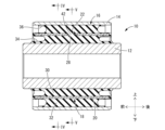
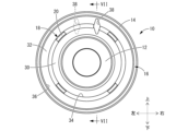
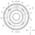
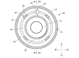
- FIG. 1 is a front view of a cylindrical vibration isolator according to a first embodiment of the present invention.
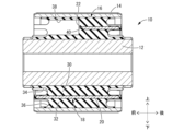
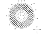
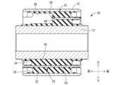
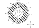
- 2 is a cross-sectional view taken along line II-II of FIG. 3 is a cross-sectional view taken along line III-III of FIG. IV-IV cross-sectional view of FIG. 2 is a cross-sectional view taken along the line VV in FIG.
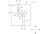
- FIG. 2 is a front view showing the cylindrical vibration isolator shown in FIG. 1 in a state before diameter reduction processing.
- 6 is a cross-sectional view taken along the line VII-VII of FIG. 8 is a cross-sectional view taken along the line VIII-VIII of FIG. IX-IX cross-sectional view of FIG. FIG.
- FIG. 7 is a plan view of an intermediate sleeve constituting the cylindrical vibration isolator shown in FIG.
- FIG. 2 is a plan view of an intermediate sleeve constituting the cylindrical vibration isolator shown in FIG.
- FIG. 11 is a front view showing a cylindrical vibration isolator according to a second embodiment of the present invention in a state before being subjected to diameter reduction processing.
- FIG. 12 is a plan view of an intermediate sleeve constituting the cylindrical vibration isolator shown in FIG.
- FIG. 14B is a plan view showing the intermediate sleeve shown in FIG. 14A in a state after diameter reduction processing;
- FIG. 14B is a plan view showing the intermediate sleeve shown in FIG. 14A in a state after diameter reduction processing;
- FIG. 11 is a front view showing a cylindrical vibration isolator according to a third embodiment of the present invention before diameter reduction processing.
- FIG. 16 is a plan view of an intermediate sleeve constituting the cylindrical vibration isolator shown in FIG.
- FIG. 18B is a plan view showing the intermediate sleeve shown in FIG. 18A in a state after diameter reduction processing
- FIG. 13 is a plan view showing an intermediate sleeve constituting a cylindrical vibration-damping device according to a fourth embodiment of the present invention in a state prior to diameter reduction processing
- FIG. 19B is a plan view showing the intermediate sleeve shown in FIG. 19A in a state after diameter reduction processing;
- FIGS. 1 to 5 show a cylindrical vibration-damping device 10 as a first embodiment of the present invention.
- the cylindrical vibration-damping device 10 has a structure in which an inner shaft member 12 and an outer cylindrical member 14 are connected by a main rubber elastic body 16.
- the up-down direction generally refers to the up-down direction in FIG. 1
- the left-right direction generally refers to the left-right direction in FIG. 1
- the front-rear direction generally refers to the left-right direction in FIG. 2.
- FIGS. 6 to 9 show the state of the outer cylindrical member 14 of the cylindrical vibration-damping device 10 before the diameter-reducing process (integrally vulcanized product of the main rubber elastic body 16).
- the components and parts of the cylindrical vibration-damping device 10 before the diameter-reducing process will be explained, and then the deformation of the outer cylindrical member 14 due to the diameter-reducing process will be explained.
- the inner shaft member 12 is a hard member made of metal or synthetic resin, and has a thick wall and small diameter, roughly cylindrical shape.
- the inner shaft member 12 has a symmetrical shape, so the axial direction is not important.
- the outer tubular member 14 is a hard member made of metal or synthetic resin, and has a generally cylindrical shape with a thin wall and a large diameter compared to the inner axial member 12.
- the outer tubular member 14 has a shorter axial length compared to the inner axial member 12.
- the outer tubular member 14 has a symmetrical shape, regardless of axial orientation.
- the outer peripheral surfaces of both axial ends of the outer tubular member 14 are tapered, with the diameter decreasing axially outward.
- the inner shaft member 12 is inserted into the outer tubular member 14, and a cylindrical intermediate sleeve 18 is disposed between the inner shaft member 12 and the outer tubular member 14 in the radial direction.
- the intermediate sleeve 18 is a hard member formed of metal or synthetic resin, and has a cylindrical portion 20 having a generally cylindrical shape as a whole.
- the cylindrical portion 20 of the intermediate sleeve 18 in this embodiment is thinner than the outer tubular member 14.
- the axial dimension of the cylindrical portion 20 is smaller than that of the outer tubular member 14.
- the cylindrical portion 20 has a larger diameter than the inner shaft member 12 and a smaller diameter than the outer tubular member 14, and extends circumferentially between the inner shaft member 12 and the outer tubular member 14 in the radial direction.
- the cylindrical portion 20 is spaced outward from the outer circumferential surface of the inner shaft member 12, and is spaced inward from the inner circumferential surface of the outer tubular member 14.
- a slit 22 is formed in the cylindrical portion 20 of the intermediate sleeve 18, penetrating the entire portion in the axial direction.
- the slit 22 is provided in a portion of the circumference of the intermediate sleeve 18, and the intermediate sleeve 18 is divided in a portion of the circumference by the slit 22, forming an approximately C-shaped cylinder.
- the slit 22 has straight sections 24, 24 at both ends that extend in the axial direction.
- the straight section 24 extends linearly.
- the straight section 24 extends in the axial direction with a substantially constant width, but may have a taper to make it easier to remove the mold that is inserted when molding the main rubber elastic body 16 (described below).
- the axial ends of the straight section 24 are formed with guide surfaces 26 that are widened and inclined circumferentially on both sides toward the outside in the axial direction.
- the straight portions 24, 24 on both axial sides are formed at different positions in the circumferential direction of the intermediate sleeve 18, and in this embodiment, are formed at positions spaced apart from each other in the circumferential direction of the intermediate sleeve 18.
- the straight portions 24, 24 in this embodiment do not overlap each other when viewed in the axial direction, and the overlap of the straight portions 24, 24 when viewed in the axial direction is made smaller than 0. Therefore, the overlap of the straight portions 24, 24 is made smaller than the radial thickness dimension of the tubular portion 20 of the intermediate sleeve 18.
- the straight portions 24, 24 are connected to each other by the intermediate portion 28.
- the intermediate portion 28 extends in the circumferential direction of the intermediate sleeve 18, with one circumferential end connected to the front straight portion 24 and the other circumferential end connected to the rear straight portion 24.
- the width dimension w2 of the slit 22 in the intermediate portion 28 may be smaller than the width dimension w1 of the slit 22 in the straight portions 24, 24, but in this embodiment, w2>w1.
- the width dimension w1 of the slit 22 in the straight portions 24, 24 is the width dimension of the straight portion 24 in the intermediate sleeve 18 before the diameter is reduced, and is set according to the amount of diameter reduction deformation of the intermediate sleeve 18 described later.
- the intermediate sleeve 18 has a 180-degree rotational symmetric shape with respect to the symmetry axis L that extends perpendicular to the axis (perpendicular to the paper surface in FIG. 10A) through the center of the slit 22 on both axial sides, and the axial direction is not important.
- a main rubber elastic body 16 is formed between the inner shaft member 12, in which the intermediate sleeve 18 is arranged, and the outer tubular member 14 in the radial direction.
- the main rubber elastic body 16 has a thick, approximately cylindrical shape, and its inner peripheral surface is vulcanization bonded to the outer peripheral surface of the inner shaft member 12, and its outer peripheral surface is vulcanization bonded to the inner peripheral surface of the outer tubular member 14.
- the intermediate sleeve 18 is vulcanization bonded to the radial middle of the main rubber elastic body 16, and the main rubber elastic body 16 is divided into the inner peripheral side and the outer peripheral side of the intermediate sleeve 18.
- the main rubber elastic body 16 is composed of an inner peripheral rubber 30 that connects the inner shaft member 12 and the tubular portion 20 of the intermediate sleeve 18, and an outer peripheral rubber 32 that connects the tubular portion 20 of the intermediate sleeve 18 and the outer tubular member 14. Almost the entire surface of the intermediate sleeve 18 is covered by the main rubber elastic body 16, and the axial end of the tubular portion 20 is partially exposed from the main rubber elastic body 16 at multiple points in the circumferential direction.
- an inner peripheral groove 34 is formed, which opens axially outward and extends continuously in the circumferential direction.
- an outer peripheral groove 36 is formed, which opens axially outward and extends in the circumferential direction.
- the inner peripheral groove 34 and the outer peripheral groove 36 have a bottom surface on the inner side in the axial direction that is a concave surface with a substantially semicircular arc shape.
- the axial end of the cylindrical portion 20 of the intermediate sleeve 18 extends out to the radial space between the inner peripheral groove 34 and the outer peripheral groove 36.
- the axial depth of the inner peripheral groove 34 is slightly smaller than that of the outer peripheral groove 36, but the depths of the inner peripheral groove 34 and the outer peripheral groove 36 may be the same, or the outer peripheral groove 36 may be smaller.
- the main rubber elastic body 16 has voids 38, 38 formed in portions corresponding to the straight portions 24, 24 of the slit 22 of the intermediate sleeve 18.
- the voids 38 open to the axial end face of the main rubber elastic body 16 and extend linearly in the axial direction.
- the voids 38 have a generally diamond-shaped cross-sectional shape before the outer tubular member 14 is subjected to diameter reduction processing, and are flattened diamond-shaped cross-sectional shapes with a vertical diagonal longer than a horizontal diagonal.
- a portion of the void 38 is located within the straight portion 24 of the slit 22, and extends further inward and outward than the tubular portion 20 of the intermediate sleeve 18.
- the void 38 corresponding to the straight portion 24 on one side in the axial direction opens into one end face of the main rubber elastic body 16 in the axial direction and extends partway in the axial direction of the main rubber elastic body 16, while the void 38 corresponding to the straight portion 24 on the other side in the axial direction (rear side) opens into the other end face of the main rubber elastic body 16 in the axial direction and extends partway in the axial direction of the main rubber elastic body 16.
- the void 38 in this embodiment does not reach the innermost end of the straight portion 24 in the axial direction (the end on the middle portion 28 side), and a rear wall rubber 40 is provided at the innermost part of the void 38.
- the main rubber elastic body 16 is provided with an intermediate rubber 42 that fills the intermediate portion 28 of the slit 22 of the intermediate sleeve 18.
- the intermediate rubber 42 extends in the axial direction in the intermediate portion 28, and both axial ends are fixed to the intermediate sleeve 18, axially connecting both axial sides of the intermediate sleeve 18 that sandwich the intermediate portion 28.
- voids 38, 38 are located on both circumferential sides of the intermediate rubber 42.
- the intermediate rubber 42 is integrally and continuously formed with the inner rubber 30 and the outer rubber 32 in the radial direction, and the inner rubber 30 and the outer rubber 32 are integrally connected to each other by the intermediate rubber 42.
- the outer tubular member 14 is subjected to diameter reduction (drawing) to form the cylindrical vibration-damping device 10 shown in Figures 1 to 5.
- the main rubber elastic body 16 arranged radially between the inner shaft member 12 and the outer tubular member 14 is pre-compressed in the radial direction by the diameter reduction of the outer tubular member 14, and the durability of the main rubber elastic body 16 is improved because the tensile stress caused by thermal contraction after molding of the main rubber elastic body 16 is reduced.
- the method of diameter reduction of the outer tubular member 14 is not particularly limited, but a diameter reduction method such as eight-way drawing can be used, in which the outer tubular member 14 is pressed inwardly to reduce the diameter by a jig pressed against the outer peripheral surface of the outer tubular member 14 in eight radial directions.
- the outer circumferential rubber 32 arranged between the outer tubular member 14 and the intermediate sleeve 18 is compressed in the radial direction, improving the durability of the outer circumferential rubber 32.
- the elasticity of the outer circumferential rubber 32 (reaction force against compression) is exerted on the tubular portion 20 of the intermediate sleeve 18, so that a force in the diameter reducing direction also acts on the tubular portion 20. Since the tubular portion 20 is divided in the circumferential direction by the slit 22, it deforms in response to input in the diameter reducing direction so that the width of the straight portions 24, 24 in the slit 22 becomes narrower as shown in FIG. 10B.
- the tubular portion 20 of the intermediate sleeve 18 is also reduced in diameter due to the diameter reducing process of the outer tubular member 14, and the inner circumferential rubber 30 arranged between the intermediate sleeve 18 and the inner shaft member 12 is also compressed in the radial direction, improving the durability of the inner circumferential rubber 30.
- both the outer circumferential rubber 32 and the inner circumferential rubber 30 of the main rubber elastic body 16 are precompressed, advantageously improving durability.
- the voids 38, 38 formed in the portion corresponding to the straight portions 24, 24 are deformed so that the circumferential width dimension is reduced, as shown in Figures 1, 4, and 5.
- the force required for the intermediate sleeve 18 to be reduced in diameter is smaller than when the straight portions 24, 24 are filled with rubber.
- the compression spring of the rubber acts as a resistance against the reduction in diameter of the intermediate sleeve 18, so a larger force is required.
- the narrowed voids 38, 38 remain open on the axial end face, but for example, the inner walls on both sides of the circumferential direction of each void 38 may be in close contact with each other, so that the voids 38, 38 essentially disappear.
- the intermediate rubber 42 formed in the intermediate portion 28 of the slit 22 is shear deformed with both axial ends displaced relative to each other in the circumferential direction.
- the shear spring of the intermediate rubber 42 which has a smaller spring constant than the compression spring, acts as a resistance to the radial contraction of the intermediate sleeve 18, so that the intermediate sleeve 18 can be contracted in diameter with a smaller force than when the compression spring of the intermediate rubber 42 acts as a resistance.
- rear wall rubbers 40 formed integrally with the main rubber elastic body 16 are provided at the axial rear of each of the cavities 38, 38, and the rear wall rubbers 40 are integrally continuous with the intermediate rubber 42 and extend circumferentially outward from the intermediate rubber 42 to reach the inner surface of the side wall of the straight portion 24.
- the intermediate rubber 42 is not compressed purely in the circumferential direction, and a small resistance force is applied by the shear spring of the intermediate rubber 42.
- the cylindrical vibration-damping device 10 has an intermediate sleeve 18 that extends circumferentially between the inner axial member 12 and the outer tubular member 14, which allows the ratio of spring in the axis-perpendicular direction to spring for torsion in the circumferential direction (torsion direction) to be set at a higher value.
- the cylindrical vibration-damping device 10 can easily achieve both high dynamic spring in the axis-perpendicular direction and low dynamic spring in the torsion direction.
- the intermediate sleeve 18 is subjected to a blasting process as a pretreatment to enhance the adhesiveness of the main rubber elastic body 16.
- the blasting process is a process in which a blasting material (abrasive) is sprayed onto the surface of the intermediate sleeve 18 to remove the coating on the surface of the intermediate sleeve 18 and roughen the surface, thereby improving the adhesive strength of the main rubber elastic body 16.
- a large number of intermediate sleeves 18 may be treated at once.
- the blasting equipment may be equipped with a drum (treatment container) capable of accommodating a large number of intermediate sleeves 18, and the drum may be rotated or otherwise moved to move the large number of intermediate sleeves 18 within the drum while spraying the blasting material onto the intermediate sleeves 18, thereby allowing the blasting process to be performed on the large number of intermediate sleeves 18 at once.
- the intermediate sleeve 18 of this embodiment is therefore structured with straight sections 24, 24 that do not directly overlap the slits 22 when viewed in the axial direction. As a result, even if another intermediate sleeve 18 (cylindrical section 20) enters the slit 22 of the intermediate sleeve 18, the other intermediate sleeve 18 does not enter continuously across both straight sections 24, 24, and the other intermediate sleeve 18 can easily come out of the slit 22 and be separated.
- intermediate sleeve 18 and the other intermediate sleeve 18 have been described separately, but the intermediate sleeve 18 and the other intermediate sleeve 18 are both substantially the same and have the structure according to this embodiment.
- FIGS. 11 to 13 show a cylindrical vibration-damping device 50 according to a second embodiment of the present invention before the outer cylindrical member 14 is subjected to diameter reduction processing.
- the cylindrical vibration-damping device 50 includes an intermediate sleeve 52.
- components and parts that are substantially the same as those in the first embodiment are given the same reference numerals as in the first embodiment, and descriptions thereof may be omitted.
- the intermediate sleeve 52 has a tubular portion 54 that is generally cylindrical in shape as a whole.
- the tubular portion 54 is divided in the circumferential direction by a slit 56 at a portion in the circumferential direction.
- the slit 56 has straight portions 24, 24 that extend linearly in the axial direction from both axial ends of the tubular portion 54.
- the straight portions 24, 24 of this embodiment are disposed at different positions in the circumferential direction of the tubular portion 54, as in the first embodiment, but are closer to each other in the circumferential direction than in the first embodiment, with a shorter circumferential separation distance of the tubular portion 54.
- the axially inner ends of the straight portions 24, 24 are directly connected, without being connected via an intermediate portion 28 extending in the circumferential direction as in the first embodiment.
- Vacancies 38, 38 are formed in the portions of the main rubber elastic body 16 that correspond to the straight sections 24, 24. Since the straight sections 24, 24 of the slit 56 are adjacent to each other in the circumferential direction, the vacancies 38, 38 formed at positions corresponding to each straight section 24 are adjacent to each other in the circumferential direction.
- a thin-film intermediate rubber 58 is formed between the adjacent innermost portions of the cavities 38, 38.
- the intermediate rubber 58 is a rubber film formed in the gap between the molds used to form the cavities 38, 38 when molding the main rubber elastic body 16, and is formed integrally with the main rubber elastic body 16.
- the intermediate rubber 58 is formed so as to connect the inner wall rubbers 40, 40 formed at the innermost portions of the cavities 38, 38 to each other.
- the intermediate sleeve 52 is deformed and reduced in diameter so that the circumferential width dimension of the straight portions 24, 24 of the slit 56 becomes smaller.
- the intermediate sleeve 52 is reduced in diameter, the axial ends of the intermediate rubber 58 are displaced relative to each other in the circumferential direction, causing shear deformation.
- the intermediate rubber 58 in this embodiment which is in the form of a thin film, may break as it is deformed.
- the cylindrical vibration-damping device 50 equipped with such an intermediate sleeve 52 can achieve the same effect as the first embodiment. Furthermore, in the cylindrical vibration-damping device 50 of this embodiment, the circumferential thickness dimension of the intermediate rubber 58 is reduced, so that when the intermediate sleeve 52 is contracted in diameter, the force resisting the contraction due to the elasticity of the intermediate rubber 58 is further reduced, and the intermediate sleeve 52 can be effectively contracted and deformed with a smaller force.
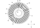
- the cylindrical vibration-damping device 60 includes an intermediate sleeve 62.
- the intermediate sleeve 62 has a tubular portion 64 that is generally cylindrical in shape.
- the tubular portion 64 is divided in the circumferential direction by a slit 66 in a part of the circumferential direction.
- the slit 66 has straight portions 24, 24 that extend linearly in the axial direction from both axial ends of the tubular portion 64.
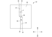
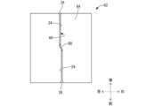
- the straight portions 24, 24 are formed at different positions in the circumferential direction of the tubular portion 64, but have a portion that directly overlaps when viewed in the axial direction, and the slit 66 extends linearly through the overlap portion in the axial direction.
- the circumferential width (overlap margin) d of the overlap portion of the straight portions 24, 24 when viewed in the axial direction is smaller than the radial thickness dimension of the tubular portion 64 of the intermediate sleeve 62. Therefore, even if the tubular portion 64 of another intermediate sleeve 62 enters the slit 66 of the intermediate sleeve 62 from the side of one straight portion 24, the other intermediate sleeve 62 is prevented from entering beyond the connection portion of the straight portions 24, 24 and into the other straight portion 24.
- An intermediate rubber 68 is formed at the connection between the straight sections 24, 24.
- the intermediate rubber 68 is located at the back of each of the straight sections 24, 24, and connects the inner walls on both sides of the slit 66 in the circumferential direction at the connection between the straight sections 24, 24.
- the intermediate sleeve 62 is deformed and reduced in diameter so that the circumferential width dimension of the straight portions 24, 24 of the slit 66 becomes smaller.
- the intermediate rubber 68 is compressed and deformed in the circumferential direction, but because the axial length dimension of the intermediate rubber 68 is made sufficiently small, the resistance of the compression spring of the intermediate rubber 68 when the intermediate sleeve 62 is reduced in diameter is unlikely to be a problem.
- the cylindrical vibration-damping device 60 equipped with such an intermediate sleeve 62 can also provide the same effect as the first embodiment.
- the straight portions 24, 24 of the slit 66 do not necessarily have to be positioned at positions separated in the circumferential direction, and even if they partially overlap when viewed in the axial direction, the same effect can be obtained as long as the overlap amount is specified so that the entry of other intermediate sleeves 62 into the slits is restricted.
- FIG. 19 shows an intermediate sleeve 70 constituting a cylindrical vibration-damping device according to a fourth embodiment of the present invention. Note that in this embodiment, only the intermediate sleeve 70 and intermediate rubber 82, which will be described later, are shown, but the other parts of the cylindrical vibration-damping device (not shown) can have the same structure as the first embodiment.
- the intermediate sleeve 70 has a tubular portion 72 that is generally cylindrical in shape overall.
- the tubular portion 72 is divided in the circumferential direction by a slit 74 at a portion of the circumferential direction.
- the slit 74 has straight portions 24, 24 that extend linearly in the axial direction from both axial ends of the tubular portion 72.
- the straight portions 24, 24 are formed at the same positions relative to each other in the circumferential direction of the intermediate sleeve 70.
- the slit 74 has an intermediate portion 76 that connects the straight portions 24, 24 to each other.
- the intermediate portion 76 has an axial extension portion 78 that extends in the axial direction at a different circumferential position from the straight portions 24, 24, and circumferential extension portions 80, 80 that connect the inner ends of the straight portions 24, 24 to both ends of the axial extension portion 78.
- the intermediate portion 76 has an inverted U-shape in plan view, and both ends are connected to each of the straight portions 24.
- An intermediate rubber 82 is fixed to the intermediate portion 76 of the slit 74.
- the intermediate rubber 82 is integrally formed with the main rubber elastic body (16) (not shown) and is provided over the entire intermediate portion 76.
- the intermediate sleeve 70 is deformed and reduced in diameter so that the circumferential width dimension of the straight portions 24, 24 of the slits 74 is reduced, as shown in FIG. 19B.
- the intermediate rubber 82 is compressed in the circumferential direction, but if the axial length dimension of the intermediate rubber 82 is sufficiently small, it is possible to prevent the resistance of the compression spring of the intermediate rubber 82 from becoming a problem when the intermediate sleeve 70 is reduced in diameter.
- the axial length of the axial extension portion 78 can be made sufficiently small, and for example, the width dimension of the axial extension portion 78 and/or the width dimension of the circumferential extension portion 80 may be set larger than the width dimension of the straight portion 24.
- the overall shape of the intermediate portion 76 is not limited to a U-shape when viewed from the front as shown in the example, but may be an arc shape, etc.
- a cylindrical vibration-damping device equipped with such an intermediate sleeve 70 can achieve the same effect as the first embodiment.
- the straight sections 24, 24 do not necessarily have to be provided at different positions in the circumferential direction, and as long as the intermediate section 76 limits the entry of other intermediate sleeves 70, the same effect as the above embodiment can be achieved.
- the straight portion 24 of the slit 22 may have a width dimension that varies in the axial direction.
- the straight portion 24 may have a width dimension that gradually increases toward both ends in the axial direction.
- the intermediate portion 28 connecting the straight portions 24, 24 in the slit 22 may extend in the circumferential direction while inclining in the axial direction, or the inclination angle may vary in the circumferential direction.
- the opening shape of the cavity 38 formed in the main rubber elastic body 16 is not limited to the approximate diamond shape shown in the above embodiment, but may be an approximate circle, including an oval, or an approximate rectangle, etc.
- the intermediate rubber formed in the slit is not essential and does not have to be formed. Furthermore, if an intermediate rubber is formed, it is desirable that the intermediate rubber is arranged so that it undergoes shear deformation when the intermediate sleeve undergoes radial contraction deformation, but as shown in the third and fourth embodiments, some parts may be compressed when the intermediate sleeve undergoes radial contraction deformation, or the entire intermediate sleeve may be compressed.
- blasting is exemplified as a process that may cause other intermediate sleeves to get into the slits of the intermediate sleeve, but for example, when processing the intermediate sleeve other than blasting, such as spraying an adhesive or the like, the intrusion of other intermediate sleeves into the slits of the intermediate sleeve may be suppressed.
- Cylindrical vibration isolation device (first embodiment) Reference Signs List 12 Inner shaft member 14 Outer cylindrical member 16 Main rubber elastic body 18 Intermediate sleeve 20 Cylindrical portion 22 Slit 24 Straight portion 26 Guide surface 28 Intermediate portion 30 Inner circumferential rubber 32 Outer circumferential rubber 34 Inner circumferential groove 36 Outer circumferential groove 38 Void 40 Back wall rubber 42 Intermediate rubber 50 Cylindrical vibration-proof device (second embodiment) 52 intermediate sleeve 54 cylindrical portion 56 slit 58 intermediate rubber 60 cylindrical vibration isolator (third embodiment) 62 Intermediate sleeve 64 Cylindrical portion 66 Slit 68 Intermediate rubber 70 Intermediate sleeve (fourth embodiment) 72 Cylindrical portion 74 Slit 76 Intermediate portion 78 Axial extension portion 80 Circumferential extension portion 82 Intermediate rubber
Landscapes
- Engineering & Computer Science (AREA)
- General Engineering & Computer Science (AREA)
- Mechanical Engineering (AREA)
- Springs (AREA)
Abstract
Description
12 インナ軸部材
14 アウタ筒部材
16 本体ゴム弾性体
18 中間スリーブ
20 筒状部
22 スリット
24 ストレート部
26 案内面
28 中間部
30 内周ゴム
32 外周ゴム
34 内周すぐり溝
36 外周すぐり溝
38 空所
40 奥壁ゴム
42 中間ゴム
50 筒形防振装置(第二の実施形態)
52 中間スリーブ
54 筒状部
56 スリット
58 中間ゴム
60 筒形防振装置(第三の実施形態)
62 中間スリーブ
64 筒状部
66 スリット
68 中間ゴム
70 中間スリーブ(第四の実施形態)
72 筒状部
74 スリット
76 中間部
78 軸方向延伸部
80 周方向延伸部
82 中間ゴム
Claims (4)
- インナ軸部材とアウタ筒部材が本体ゴム弾性体で連結されており、該インナ軸部材と該アウタ筒部材との径方向間を周方向に延びる筒状の中間スリーブが該本体ゴム弾性体に固着された筒形防振装置であって、
前記中間スリーブの周方向の一部には、軸方向に貫通するスリットが形成されており、
該スリットの両端部分が軸方向に延びるストレート部とされており、
両側の該ストレート部の軸方向視における直接のオーバーラップ代が、該中間スリーブの径方向厚さ寸法よりも小さくされている筒形防振装置。 - 前記スリットの両側の前記ストレート部が、前記中間スリーブにおける周方向の相互に異なる位置に形成されており、
該スリットは、両側の該ストレート部を周方向で相互につなぐ中間部を備えている請求項1に記載の筒形防振装置。 - 前記スリットの前記中間部には、前記中間スリーブの該中間部に対する軸方向両側部分を相互に連結する中間ゴムが設けられている請求項2に記載の筒形防振装置。
- インナ軸部材とアウタ筒部材の径方向間を周方向に延びる筒状部を備えており、該筒状部が本体ゴム弾性体によって該インナ軸部材及び該アウタ筒部材に連結される筒形防振装置用の中間スリーブであって、
前記筒状部の周方向の一部には、軸方向に貫通するスリットが形成されており、
該スリットの両端部分が軸方向に延びるストレート部とされており、
両側の該ストレート部の軸方向視における直接のオーバーラップ代が、該筒状部の径方向厚さ寸法よりも小さくされている中間スリーブ。
Priority Applications (3)
| Application Number | Priority Date | Filing Date | Title |
|---|---|---|---|
| CN202380025125.7A CN119278324A (zh) | 2022-09-28 | 2023-09-07 | 筒形防振装置 |
| DE112023001921.5T DE112023001921T5 (de) | 2022-09-28 | 2023-09-07 | Zylindrischer schwingungsisolator |
| US18/735,192 US20240328476A1 (en) | 2022-09-28 | 2024-06-06 | Cylindrical vibration isolator and intermediate sleeve |
Applications Claiming Priority (2)
| Application Number | Priority Date | Filing Date | Title |
|---|---|---|---|
| JP2022-155048 | 2022-09-28 | ||
| JP2022155048A JP2024048898A (ja) | 2022-09-28 | 2022-09-28 | 筒形防振装置 |
Related Child Applications (1)
| Application Number | Title | Priority Date | Filing Date |
|---|---|---|---|
| US18/735,192 Continuation US20240328476A1 (en) | 2022-09-28 | 2024-06-06 | Cylindrical vibration isolator and intermediate sleeve |
Publications (1)
| Publication Number | Publication Date |
|---|---|
| WO2024070560A1 true WO2024070560A1 (ja) | 2024-04-04 |
Family
ID=90477392
Family Applications (1)
| Application Number | Title | Priority Date | Filing Date |
|---|---|---|---|
| PCT/JP2023/032640 Ceased WO2024070560A1 (ja) | 2022-09-28 | 2023-09-07 | 筒形防振装置 |
Country Status (5)
| Country | Link |
|---|---|
| US (1) | US20240328476A1 (ja) |
| JP (1) | JP2024048898A (ja) |
| CN (1) | CN119278324A (ja) |
| DE (1) | DE112023001921T5 (ja) |
| WO (1) | WO2024070560A1 (ja) |
Citations (4)
| Publication number | Priority date | Publication date | Assignee | Title |
|---|---|---|---|---|
| JPS6149142U (ja) * | 1984-09-06 | 1986-04-02 | ||
| JP2002048176A (ja) * | 2000-08-04 | 2002-02-15 | Honda Motor Co Ltd | 弾性ブッシュ |
| JP2013204726A (ja) * | 2012-03-28 | 2013-10-07 | Toyo Tire & Rubber Co Ltd | 防振装置 |
| JP2014092218A (ja) * | 2012-11-02 | 2014-05-19 | Yamashita Rubber Co Ltd | 防振装置 |
-
2022
- 2022-09-28 JP JP2022155048A patent/JP2024048898A/ja active Pending
-
2023
- 2023-09-07 CN CN202380025125.7A patent/CN119278324A/zh active Pending
- 2023-09-07 DE DE112023001921.5T patent/DE112023001921T5/de active Pending
- 2023-09-07 WO PCT/JP2023/032640 patent/WO2024070560A1/ja not_active Ceased
-
2024
- 2024-06-06 US US18/735,192 patent/US20240328476A1/en active Pending
Patent Citations (4)
| Publication number | Priority date | Publication date | Assignee | Title |
|---|---|---|---|---|
| JPS6149142U (ja) * | 1984-09-06 | 1986-04-02 | ||
| JP2002048176A (ja) * | 2000-08-04 | 2002-02-15 | Honda Motor Co Ltd | 弾性ブッシュ |
| JP2013204726A (ja) * | 2012-03-28 | 2013-10-07 | Toyo Tire & Rubber Co Ltd | 防振装置 |
| JP2014092218A (ja) * | 2012-11-02 | 2014-05-19 | Yamashita Rubber Co Ltd | 防振装置 |
Also Published As
| Publication number | Publication date |
|---|---|
| JP2024048898A (ja) | 2024-04-09 |
| US20240328476A1 (en) | 2024-10-03 |
| CN119278324A (zh) | 2025-01-07 |
| DE112023001921T5 (de) | 2025-02-20 |
Similar Documents
| Publication | Publication Date | Title |
|---|---|---|
| US20050254888A1 (en) | Torque rod and method of producing the same | |
| JP2008213751A (ja) | 防振ブッシュ付スタビライザバー及びその製造方法 | |
| JP3772792B2 (ja) | 防振ブッシュ | |
| JP2002098193A (ja) | 筒型ダイナミックダンパ | |
| JP4146210B2 (ja) | 防振ブッシュの製造方法 | |
| JP4716387B2 (ja) | 防振ブッシュ | |
| JP6872316B2 (ja) | プロペラシャフト用ダイナミックダンパ | |
| WO2024070560A1 (ja) | 筒形防振装置 | |
| JP3951274B1 (ja) | 防振ブッシュの製造方法 | |
| JPH10274268A (ja) | 防振ブッシュおよびブッシュ組立体 | |
| JP2005344764A (ja) | 防振ブッシュ | |
| JP4624494B2 (ja) | 筒状ダイナミックダンパ及びその製造方法 | |
| JP2004028267A (ja) | 防振ブッシュ | |
| JP2024053466A (ja) | 筒形防振装置 | |
| JP2010137688A (ja) | 防振ブッシュ付きスタビライザバーの製造方法 | |
| US20190360551A1 (en) | Liquid-filled vibration isolator | |
| JP3932025B2 (ja) | 防振ブッシュ | |
| JP2010159860A (ja) | 防振ブッシュ | |
| JP3924729B1 (ja) | 防振ブッシュ | |
| JP4027346B2 (ja) | 防振ゴムブッシュ | |
| JP3715212B2 (ja) | 筒形ゴムマウントおよびその製造方法 | |
| WO2022209237A1 (ja) | 摺動ブッシュ | |
| JP2010006337A (ja) | 防振ブッシュ付きスタビライザバーの製造方法及び防振ブッシュ付きスタビライザバー | |
| JP4358874B2 (ja) | 防振ブッシュ | |
| KR20220017235A (ko) | 차량용 마운팅 부시 |
Legal Events
| Date | Code | Title | Description |
|---|---|---|---|
| 121 | Ep: the epo has been informed by wipo that ep was designated in this application |
Ref document number: 23871799 Country of ref document: EP Kind code of ref document: A1 |
|
| WWE | Wipo information: entry into national phase |
Ref document number: 202380025125.7 Country of ref document: CN |
|
| WWE | Wipo information: entry into national phase |
Ref document number: 112023001921 Country of ref document: DE |
|
| WWP | Wipo information: published in national office |
Ref document number: 202380025125.7 Country of ref document: CN |
|
| WWP | Wipo information: published in national office |
Ref document number: 112023001921 Country of ref document: DE |
|
| 122 | Ep: pct application non-entry in european phase |
Ref document number: 23871799 Country of ref document: EP Kind code of ref document: A1 |