WO2024070547A1 - ダンパ装置 - Google Patents
ダンパ装置 Download PDFInfo
- Publication number
- WO2024070547A1 WO2024070547A1 PCT/JP2023/032549 JP2023032549W WO2024070547A1 WO 2024070547 A1 WO2024070547 A1 WO 2024070547A1 JP 2023032549 W JP2023032549 W JP 2023032549W WO 2024070547 A1 WO2024070547 A1 WO 2024070547A1
- Authority
- WO
- WIPO (PCT)
- Prior art keywords
- plate
- damper device
- disc plate
- hub
- throttling
- Prior art date
- Legal status (The legal status is an assumption and is not a legal conclusion. Google has not performed a legal analysis and makes no representation as to the accuracy of the status listed.)
- Ceased
Links
Images







Classifications
-
- F—MECHANICAL ENGINEERING; LIGHTING; HEATING; WEAPONS; BLASTING
- F16—ENGINEERING ELEMENTS AND UNITS; GENERAL MEASURES FOR PRODUCING AND MAINTAINING EFFECTIVE FUNCTIONING OF MACHINES OR INSTALLATIONS; THERMAL INSULATION IN GENERAL
- F16F—SPRINGS; SHOCK-ABSORBERS; MEANS FOR DAMPING VIBRATION
- F16F15/00—Suppression of vibrations in systems; Means or arrangements for avoiding or reducing out-of-balance forces, e.g. due to motion
- F16F15/10—Suppression of vibrations in rotating systems by making use of members moving with the system
- F16F15/12—Suppression of vibrations in rotating systems by making use of members moving with the system using elastic members or friction-damping members, e.g. between a rotating shaft and a gyratory mass mounted thereon
- F16F15/131—Suppression of vibrations in rotating systems by making use of members moving with the system using elastic members or friction-damping members, e.g. between a rotating shaft and a gyratory mass mounted thereon the rotating system comprising two or more gyratory masses
- F16F15/133—Suppression of vibrations in rotating systems by making use of members moving with the system using elastic members or friction-damping members, e.g. between a rotating shaft and a gyratory mass mounted thereon the rotating system comprising two or more gyratory masses using springs as elastic members, e.g. metallic springs
- F16F15/1338—Motion-limiting means, e.g. means for locking the spring unit in pre-defined positions
-
- F—MECHANICAL ENGINEERING; LIGHTING; HEATING; WEAPONS; BLASTING
- F16—ENGINEERING ELEMENTS AND UNITS; GENERAL MEASURES FOR PRODUCING AND MAINTAINING EFFECTIVE FUNCTIONING OF MACHINES OR INSTALLATIONS; THERMAL INSULATION IN GENERAL
- F16F—SPRINGS; SHOCK-ABSORBERS; MEANS FOR DAMPING VIBRATION
- F16F15/00—Suppression of vibrations in systems; Means or arrangements for avoiding or reducing out-of-balance forces, e.g. due to motion
- F16F15/10—Suppression of vibrations in rotating systems by making use of members moving with the system
- F16F15/12—Suppression of vibrations in rotating systems by making use of members moving with the system using elastic members or friction-damping members, e.g. between a rotating shaft and a gyratory mass mounted thereon
- F16F15/131—Suppression of vibrations in rotating systems by making use of members moving with the system using elastic members or friction-damping members, e.g. between a rotating shaft and a gyratory mass mounted thereon the rotating system comprising two or more gyratory masses
- F16F15/133—Suppression of vibrations in rotating systems by making use of members moving with the system using elastic members or friction-damping members, e.g. between a rotating shaft and a gyratory mass mounted thereon the rotating system comprising two or more gyratory masses using springs as elastic members, e.g. metallic springs
- F16F15/134—Wound springs
Definitions
- the technology disclosed in this application relates to a damper device.
- a damper device is provided on the torque transmission path between a driving source such as an engine and the transmission to absorb torque vibrations transmitted from the driving source to the transmission.
- the damper device disclosed in Patent Document 1 JP Patent Publication No. 2021-028520
- the damper device disclosed in Patent Document 1 includes a lining plate (reference number 100 in Patent Document 1) to which power is transmitted from a flywheel, a disc plate (reference number 200 in Patent Document 1) including a first plate (reference number 201 in Patent Document 1) to which power is transmitted from the lining plate and which rotates around a rotation axis, and a second plate (reference number 202 in Patent Document 1) arranged opposite the first plate and which rotates integrally with the first plate, and a hub (reference number 300 in Patent Document 1) that is elastically connected to the disc plate with an elastic mechanism (reference number 400 in Patent Document 1) sandwiched between the disc plate and the hub, and rotates relative to the disc plate.
- a protrusion (reference number 306 in Patent Document 1) provided on the outer periphery of the hub abuts against a restricting portion (reference number 210 in Patent Document 1) that is the outer edge of a notch provided in the first plate and is formed by bending this plate, thereby functioning as a stopper to restrict relative rotation of the hub to the disc plate beyond a predetermined angle (see Figure 4 of Patent Document 1).
- the entire contents of Patent Document 1 are incorporated herein by reference.
- the damper device disclosed in Patent Document 2 (International Publication No. WO 2007/124709) is another known example of a damper device.
- the damper device disclosed in Patent Document 2 includes a drive disk (reference number 2 in Patent Document 2) to which power is transmitted from the engine, a flange portion (reference number 15 in Patent Document 2) that is coupled to the drive disk via a spring, and a hub portion (reference number 16 in Patent Document 2) that is fixed to the flange portion.
- the restricting portion is formed by bending the first plate, so the size of the portion of the restricting portion that abuts against the protrusion of the hub cannot be made larger than the thickness of the first plate.
- the pressure (surface pressure) applied by the protrusion of the hub to the portion of the restricting portion that abuts against the protrusion of the hub increases, resulting in localized stress concentration. Therefore, it is considered necessary to take some additional measures to reinforce the strength of the restricting portion.
- the technology disclosed in this application provides a damper device equipped with a stopper with improved performance.
- the damper device comprises: a first rotating body including a first plate to which power is transmitted from a flywheel and which rotates around a rotating shaft; and a second plate that faces the first plate and is disposed at a distance from the first plate and rotates integrally with the first plate around the rotating shaft; and a second rotating body that extends or contracts an elastic mechanism portion disposed between the first rotating body and the second rotating body along the circumferential direction to rotate relative to the first rotating body around the rotating shaft and includes an engagement portion that protrudes radially outward at the outer circumferential edge, and the first plate a first squeezing portion recessed from a first main surface of the first plate toward the second plate, the second plate being provided opposite the first squeezing portion, recessed from a second main surface of the second plate toward the first squeezing portion, and fixed to the first squeezing portion using a fastening member, and the first squeezing portion and the second squeezing portion abut against the engaging portion of
- the technology disclosed in this application makes it possible to provide a damper device equipped with a stopper with improved performance.
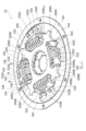
- FIG. 1 is a perspective view illustrating an example of a configuration of a damper device according to an embodiment
- FIG. 2 is a top view illustrating a schematic configuration of the damper device illustrated in FIG. 1
- FIG. 2 is a perspective view showing a schematic configuration of a portion of the damper device shown in FIG. 1
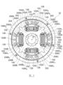
- FIG. 4 is a top view illustrating a schematic configuration of the damper device illustrated in FIG. 3
- 4 is an enlarged perspective view showing a schematic configuration of a portion of the damper device shown in FIG. 3, as viewed from a different viewpoint from that of FIG. 3
- FIG. 2 is an enlarged perspective view showing a schematic configuration of a portion of the damper device shown in FIG. 1 as viewed from a different viewpoint from that of FIG. 1 .
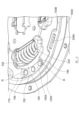
- FIG. 4 is an enlarged perspective view showing a schematic view of a part of the configuration of the damper device shown in FIG. 3 in which a rib is provided on a first throttle portion 120.
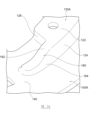
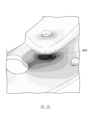
- FIG. 7B is a diagram showing a schematic distribution of stress acting on the first throttle portion 120 and its periphery when the engagement portion 208 of the hub 200 abuts against the first throttle portion 120 in the damper device shown in FIG. 7A.
- FIG. 7B is a diagram showing a schematic distribution of stress acting on the first throttle portion 120 and its periphery when the engagement portion 208 of the hub 200 abuts against the first throttle portion 120 in the damper device shown in FIG. 7A.
- FIG. 7B is a perspective view showing an enlarged schematic view of a portion of the damper device shown in FIGS. 1 to 6 as a comparative example of the damper device shown in FIG. 7A.
- FIG. 7A is a perspective view showing an enlarged schematic view of a portion of the damper device shown in FIGS. 1 to 6 as a comparative example of the damper device shown in FIG. 7A.
- FIG. 8B is a diagram showing a schematic distribution of stress acting on the first throttle portion 120 and its surroundings when the engagement portion 208 of the hub 200 abuts against the first throttle portion 120 in the damper device shown in FIG. 8A.
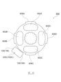
- FIG. This figure shows a schematic diagram of the amount of axial displacement that occurs between the first disc plate 100A and the second disc plate B when each engagement portion 208 of the hub 200 abuts against the corresponding first throttling portion and each second throttling portion in the damper device shown in Figures 1 to 6.
- FIG. 4 is a perspective view showing a schematic configuration of another hub used in the damper device shown in FIG.
- FIG. 10 is a top view illustrating a schematic configuration of the hub illustrated in FIG. 9 .
- Fig. 1 is a perspective view that typically shows an example of the configuration of a damper device according to one embodiment.
- Fig. 2 is a top view that typically shows the configuration of the damper device shown in Fig. 1.
- Fig. 3 is a perspective view that typically shows the configuration of a portion of the damper device shown in Fig. 1.
- Fig. 4 is a top view that typically shows the configuration of the damper device shown in Fig. 3.
- FIG. 3 shows the damper device in a state where the second disc plate 100B of the disc plate 100, which will be described later, has been removed from FIG. 1
- FIG. 4 shows the damper device in a state where the second disc plate 100B, which will be described later, has been removed from FIG. 2.
- the damper device 10 can transmit driving force from a driving source such as an engine or a motor to a transmission by being clamped between a flywheel (not shown) and a pressure plate (not shown).
- a driving source such as an engine or a motor
- a pressure plate not shown
- the structure for clamping the damper device 10 between the flywheel and the pressure plate is well known, so a detailed description thereof will be omitted.
- the damper device 10 can absorb and damp vibrations in the torsional direction.
- the damper device 10 can include a disc plate 100 as a first rotating body to which power is transmitted directly from a flywheel (not shown) or indirectly via another member, a hub 200 as a second rotating body that is connected to an input shaft of a transmission (not shown), and at least one elastic mechanism 300 that is disposed between the disc plate 100 and the hub 200 and extends in the circumferential direction.
- Hub 200 The hub 200 may be located on the output side of the power transmission path.
- Hub 200 is formed, for example, from a metal material, has a shape that extends in a generally annular shape as a whole, and can be provided to be rotatable around rotation axis O.
- hub 200 can be splined to an input shaft (not shown) of a transmission (not shown) by inserting the input shaft through a through hole 204 formed in a generally annular cylindrical portion 202.
- the hub 200 may also include a number of flanges 206 extending radially from the cylindrical portion 202.
- the hub 200 may include a total of four flanges 206 (206A, 206B, 206C, 206D) so that a total of two flanges 206 are located at both ends of each of the four storage areas 102 (102A, 102B, 102C, 102D) of the disc plate 100, as described below.
- a notch 206A1 may be formed on one side of the flange 206A (the right side of the flange 206A on the paper surface) as shown in Fig. 4. This notch 206A1 can support the first sheet member 330 of the elastic mechanism part 300 accommodated in the accommodation area 102A from the outside in the circumferential direction.
- a notch 206D2 may be formed on the other side of the flange 206D (on the left side of the flange 206D in the drawing). This notch 206D2 may support the second sheet member 332 of the elastic mechanism 300 accommodated in the accommodation area 102A from the outer side in the circumferential direction.
- a notch 206B1 may be formed on one side of the flange 206B (upper side with respect to the flange 206B on the paper surface) as shown in Fig. 4. This notch 206B1 can support the first sheet member 330 of the elastic mechanism part 300 accommodated in the accommodation area 102B from the outer side in the circumferential direction.
- a notch 206A2 may be formed on the other side of the flange 206A (on the left side of the flange 206A in the drawing). This notch 206A2 may support the second sheet member 332 of the elastic mechanism 300 accommodated in the accommodation region 102B from the outside in the circumferential direction.
- a notch 206C1 may be formed on one side of the flange 206C (the lower side with respect to the flange 206C on the paper surface) as shown in Fig. 4. This notch 206C1 can support the first sheet member 330 of the elastic mechanism part 300 accommodated in the accommodation area 102C from the outer side in the circumferential direction.
- a notch 206B2 may be formed on the other side of the flange 206B (the lower side of the flange 206B on the paper surface). This notch 206B2 may support the second sheet member 332 of the elastic mechanism 300 accommodated in the accommodation region 102C from the outer side in the circumferential direction.
- a notch 206D1 may be formed on one side of the flange 206D (the right side of the flange 206D as viewed from the paper surface) as shown in Fig. 4. This notch 206D1 can support the first sheet member 330 of the elastic mechanism 300 accommodated in the accommodation area 102D from the circumferential outer side.
- a notch 206C2 may be formed on the other side of the flange 206C (the upper side with respect to the flange 206C on the paper surface as the center). This notch 206C2 may support the second sheet member 332 of the elastic mechanism portion 300 accommodated in the accommodation region 102D from the outer side in the circumferential direction.
- the hub 200 may include an engagement portion 208 that protrudes radially outward from the outer periphery of at least one of the flanges 206A-206D.
- Figure 4 shows an example in which the hub 200 includes engagement portions 208A-208D on the outer periphery of the flanges 206A-206D, respectively.
- Each engaging portion 208 can have any shape so long as it has a shape that protrudes radially outward from the outer circumferential edge of the flange 206.
- each engaging portion 208 can have a generally trapezoidal shape when viewed from above, as illustrated in FIG. 4.
- each engaging portion 208 can have a rectangular shape, a circular shape, and/or a combination of these shapes.
- these multiple engaging portions 208 can have generally the same shape as each other, or can have different shapes as each other.
- Disc plate 100 (1) Basic Configuration The disc plate 100 may be disposed on the input side of a power transmission path.
- the disc plate 100 may be formed of, for example, a metal material.
- the disc plate 100 may include a first disc plate 100A and a second disc plate 100B as a pair of members provided on both axial sides of the hub 200.
- the first disc plate 100A and the second disc plate 100B may each have a substantially annular shape as a whole.
- the first disc plate 100A and the second disc plate 100B may be arranged at a distance from each other, and may be arranged rotatably relative to the hub 200 around the central axis O with the hub 200 and the elastic mechanism part 300 sandwiched between them.
- the first disc plate 100A may be directly connected to a flywheel (not shown) or may be connected to a lining plate fixed to a flywheel (not shown) via a friction material or the like.
- the first disc plate 100A and the second disc plate 100B connected to the first disc plate 100A may receive power from the flywheel and rotate around the rotation axis O.
- the first disc plate 100A and the second disc plate 100B can cooperate with each other to form at least one storage area 102, here, as an example, four storage areas 102A, 102B, 102C, and 102D. Each of these storage areas 102 can partially store a set of elastic mechanism parts 300 (expose a part of the set of elastic mechanism parts 300 to the outside). In order to form such storage areas 102, the first disc plate 100A and the second disc plate 100B can include openings in the parts corresponding to each storage area, as shown in Figures 1 to 4.
- the disc plate 100 can accommodate an elastic mechanism 300 in each accommodation area 102.
- the disc plate 100 can accommodate a set of elastic mechanism 300, i.e., an elastic body (elastic member) 310 and a first sheet member 330 and a second sheet member 332 arranged on either side of the elastic body 310, in the accommodation area 102A.
- the disc plate 100 can accommodate the above-mentioned set of elastic mechanism parts 300 (elastic body 310, first sheet member 330, and second sheet member 332) in each of the accommodation areas 102B, 102C, and 102D.
- the disc plate 100 can support two sheets included in the elastic mechanism portion 300 accommodated in each accommodation region 102.
- the accommodation region 102A The first end surface 104A 1 surrounding one end of the accommodation region 102A (opening) in the first disc plate 100A can abut against the first sheet member 330 from the circumferential outer side to support the first sheet member 330, as shown in FIG. 4.
- the first end surface 104B 1 surrounding one end of the accommodation region 102A (opening) in the second disc plate 100B can abut against the first sheet member 330 from the circumferential outer side to support the first sheet member 330, as shown in FIG. 2.
- the second end surface 104A2 surrounding the other end of the accommodation area 102A (opening) in the first disc plate 100A can abut against the second sheet member 332 from the circumferential outer side to support the second sheet member 332.
- the second end surface 104B2 surrounding the other end of the accommodation area 102A (opening) in the second disc plate 100B can abut against the second sheet member 332 from the circumferential outer side to support the second sheet member 332, as shown in FIG.
- a first end surface 106A1 surrounding one end of the accommodation area 102B (opening) in the first disc plate 100A can abut against the first sheet member 330 from the circumferential outside to support the first sheet member 330.
- a first end surface 106B1 surrounding one end of the accommodation area 102B (opening) in the second disc plate 100B can abut against the first sheet member 330 from the circumferential outside to support the first sheet member 330 as shown in Fig. 2.
- the second end surface 106A2 surrounding the other end of the accommodation area 102B (opening) in the first disc plate 100A can abut against the second sheet member 332 from the circumferential outer side to support the second sheet member 332.
- the second end surface 106B2 surrounding the other end of the accommodation area 102B (opening) in the second disc plate 100B can abut against the second sheet member 332 from the circumferential outer side to support the second sheet member 332, as shown in FIG.
- a first end surface 108A1 surrounding one end of the accommodation area 102C (opening) in the first disc plate 100A can abut against the first sheet member 330 from the circumferential outside to support the first sheet member 330.
- a first end surface 108B1 surrounding one end of the accommodation area 102C (opening) in the second disc plate 100B can abut against the first sheet member 330 from the circumferential outside to support the first sheet member 330 as shown in Fig. 2.
- the second end surface 108A2 surrounding the other end of the accommodation area 102C (opening) in the first disc plate 100A can abut against the second sheet member 332 from the circumferential outside to support the second sheet member 332.
- the second end surface 108B2 surrounding the other end of the accommodation area 102C (opening) in the second disc plate 100B can abut against the second sheet member 332 from the circumferential outside to support the second sheet member 332.
- a first end surface 110A1 surrounding one end of the accommodation area 102D (opening) in the first disc plate 100A can abut against the first sheet member 330 from the circumferential outside to support the first sheet member 330, as shown in Fig. 4.
- a first end surface 110B1 surrounding one end of the accommodation area 102A (opening) in the second disc plate 100B can abut against the first sheet member 330 from the circumferential outside to support the first sheet member 330, as shown in Fig. 2.
- the second end surface 110A2 surrounding the other end of the accommodation area 102D (opening) in the first disc plate 100A can abut against the second sheet member 332 from the circumferential outer side to support the second sheet member 332.
- the second end surface 110B2 surrounding the other end of the accommodation area 102D (opening) in the second disc plate 100B can abut against the second sheet member 332 from the circumferential outer side to support the second sheet member 332, as shown in FIG.
- the disc plate 100 may include a plurality of throttled portions that function as stoppers for restricting the relative rotation of the hub 200 with respect to the disc plate 100 beyond a predetermined angle.
- a total of two throttle portions may be arranged on both circumferential sides of one engagement portion 208 of the hub 200.
- One of these two throttle portions abuts against the engagement portion 208 and can restrict rotation of the hub 200 relative to the disc plate 100 in one direction (clockwise or counterclockwise) by a predetermined angle or more.
- the other of these two throttle portions abuts against the engagement portion 208 and can restrict rotation of the hub 200 in the other direction (counterclockwise or clockwise) by a predetermined angle or more.
- four engagement portions 208 (208A-208D) are provided, so that a total of four narrowing portions can be formed, with one narrowing portion positioned between two adjacent engagement portions 208.
- first throttling portions 120 (120A, 120B, 120C, 120D) may be formed in the first disc plate 100A.
- the first throttling portions 120A, 120B, 120C, 120D may be disposed adjacent to the accommodation regions 102A, 102B, 102C, 102D, respectively.
- each first throttling portion 120 can be disposed adjacent to the outer diameter side of the corresponding storage area 102.
- each first throttling portion 120 is disposed adjacent to the inner diameter side of the corresponding storage area 102, it is possible to reduce the diameter of the first disc plate 100A, and therefore the diameter of the disc plate 100.
- FIG. 5 is a perspective view showing a schematic enlarged view of a portion of the damper device shown in FIG. 3, viewed from a different perspective than FIG. 3.
- the first narrowing portion 120A can have a shape recessed from the flat first main surface 140 of the first disc plate 100A in a direction toward the second disc plate 100B (upward on the page). Note that the first main surface 140 can extend, for example, in a substantially annular shape on the first disc plate 100A.
- the first narrowing portion 120A can include a first fixed surface 122 that extends approximately parallel to the first main surface 140, and a first wall surface 124 that surrounds the periphery of the first fixed surface 122 and continuously connects the first main surface 140 and the first fixed surface 122.
- the first fixed surface 122 may be formed substantially entirely as a flat surface.
- the first fixed surface 122 may extend in an arc shape along the circumferential direction of the first disc plate 100A.
- the first fixed surface 122 may be fixed to the second fixed surface 152 of the second narrowing portion 150A (described later) formed on the second disc plate 100B using at least one fastening member (e.g., a rivet) R (a total of three in Figures 3 and 4). This allows the first disc plate 100A and the second disc plate 100B to be joined to each other by at least one fastening member R.
- a fastening member e.g., a rivet
- the first wall surface 124 can be formed, for example, by a combination of a flat surface and a curved surface.
- a surface (first abutment surface) 126 facing the engaging portion 208A can abut against this engaging portion 208A and function as a stopper that restricts further rotation of the hub 200 in the clockwise direction relative to the disc plate 100.
- a surface (first abutment surface) 128 facing the engaging portion 208D can abut against this engaging portion 208D and function as a stopper that restricts further rotation of the hub 200 in the counterclockwise direction relative to the disc plate 100.
- the first abutment surfaces 126, 128 can be arranged on a circumference that extends with a radius equal to the distance between the rotation center O of the damper device 10 and the fastening member R, i.e., at a position that overlaps the circumference.
- the diameter of the first disc plate 100A can be made smaller, i.e., the first disc plate 100A can be made more compact, compared to a configuration in which the first abutment surfaces 126, 128 are not on the circumference, i.e., are not overlapping with the circumference.
- the surface (first support surface) 130 of the first wall surface 124 that faces the elastic mechanism 300 can be provided to surround the storage area 102A. This allows the first support surface 130 to support the first sheet member 330 and the second sheet member 332 from the radial outside of the first disc plate 100A. With this configuration, the diameter of the first disc plate 100A can be made smaller, i.e., the first disc plate 100A can be made more compact, compared to a configuration in which the first support surface 130 is disposed at a distance from the elastic mechanism 300.
- Each first drawn portion 120 including the first drawn portion 120A, can be formed, for example, by press molding the flat first main surface 140 of the first disc plate 100A.
- a total of four second drawn portions 150 may be formed in the second disc plate 100B.
- the second drawn portions 150A, 150B, 150C, and 150D may be disposed adjacent to the accommodation regions 102A, 102B, 102C, and 102D, respectively.
- each second throttling portion 150 can be disposed adjacent to the outer diameter side of the corresponding storage area 102.
- the second choke portion 150A can have a recessed shape in a direction (vertical direction on the page) approaching the corresponding first choke portion 120 (here, first choke portion 120A) formed on the first disc plate 100A from the flat second main surface 170 of the second disc plate 100B.
- the second main surface 170 can extend, for example, in a substantially annular shape on the second disc plate 100B.
- the second narrowing portion 150A can include a second fixed surface 152 that extends approximately parallel to the second main surface 170, and a second wall surface 154 that surrounds the periphery of the first fixed surface 152 and continuously connects the second main surface 170 and the second fixed surface 152.
- the second fixing surface 152 may be formed substantially entirely as a flat surface.
- the second fixing surface 152 may extend in an arc shape along the circumferential direction of the second disc plate 100B.
- the second fixing surface 152 may be fixed to the first drawn portion 120A formed in the first disc plate 100A using at least one fastening member (e.g., a rivet) R (a total of three in Figs. 1 and 2).
- the second wall surface 154 can be formed, for example, by a combination of a flat surface and a curved surface.
- a surface (second abutment surface) 156 facing the engaging portion 208A can abut against this engaging portion 208A and function as a stopper that restricts further rotation of the hub 200 in the clockwise direction relative to the disc plate 100.
- a surface (second abutment surface) 158 facing the engaging portion 208D can abut against this engaging portion 208D and function as a stopper that restricts further rotation of the hub 200 in the counterclockwise direction relative to the disc plate 100.
- the second abutment surfaces 156, 158 can be arranged on a circumference that extends with a radius equal to the distance between the rotation center O of the damper device 10 and the fastening member R, i.e., at a position that overlaps with the circumference.
- the diameter of the second disc plate 100B can be made smaller, i.e., the second disc plate 100B can be made more compact, compared to a configuration in which the second abutment surfaces 156, 158 are not on the circumference, i.e., are not overlapped with the circumference.
- the surface (second support surface) 160 of the second wall surface 154 that faces the elastic mechanism portion 300 can be provided to surround the storage area 102A. This allows the second support surface 160 to support the first sheet member 330 and the second sheet member 332 from the radial outside of the second disc plate 100B. With this configuration, the diameter of the second disc plate 100B can be made smaller, i.e., the second disc plate 100B can be made more compact, compared to a configuration in which the second support surface 160 is disposed at a distance from the elastic mechanism portion 300.
- Each second drawn portion 150 including the second drawn portion 150A, can be formed, for example, by press molding the flat second main surface 170 of the second disc plate 100B.
- Figures 1 to 6 show an initial state in which no driving force is transmitted to the damper device 10 from a driving source such as an engine or a motor, or a state in which no phase difference occurs between the disc plate 100 and the hub 200.
- Power from a driving source such as an engine or a motor can be transmitted in the following order: disc plate 100, second sheet 332, elastic body 310, first sheet 330, and hub 200. Focusing on the accommodation area 102A, the power is first transmitted from the second end surface 104A2 ( 104B2 ) of the disc plate 100 to the second sheet 332. The second sheet 332 transmits the power to the first sheet 330 while bending the elastic body 310. The first sheet 330 can transmit the power to the hub 200 via the notch 206A1 of the hub 200.
- force can be transmitted from the second end surface 106A 2 (106B 2 ) of the disc plate 100 to the notch 206B 1 of the hub 200 via the elastic mechanism 300 disposed in the accommodation area 102B.
- the force can be transmitted from the second end surface 108A 2 (108B 2 ) of the disc plate 100 to the notch 206C 1 of the hub 200 via the elastic mechanism 300 disposed in the accommodation area 102C.
- the force can be transmitted from the second end surface 110A 2 (110B 2 ) of the disc plate 100 to the notch 206D 1 of the hub 200 via the elastic mechanism 300 disposed in the accommodation area 102D.
- the disc plate 100 can rotate counterclockwise relative to the hub 200, although this is not shown in Figs. 1 to 6.
- the second sheet 332 is pressed toward the first sheet 330 by the second end surface 104A 2 (104B 2 ), and moves away from the notch 206D 2 of the hub 200 against the elastic body 310 and approaches the first sheet 330.
- the hub 200 is relatively stationary, the first sheet 330 supported by the notch 206A 1 of the hub 200 does not slide. Therefore, the elastic body 310 contracts, and the first end surface 104A 1 (104B 1 ) of the disc plate 100 releases its support for the first sheet 330 and moves away from the first sheet 330.
- the elastic body 310 expands to return to its original shape, and the first sheet 330 biased by the elastic body 310 presses the notch 206A1 of the hub 200 in the counterclockwise direction on the page, causing the hub 200 to rotate counterclockwise, which in turn causes the input shaft of the transmission (not shown) to rotate.
- first abutment surface 126 of the first throttling portion 120A and the second abutment surface 156 of the second throttling portion 150A provided in correspondence with the storage area 102A abut against the engagement portion 208A formed on the hub 200.
- first abutment surface 126 of the first throttling portion 120A and the second abutment surface 156 of the second throttling portion 150A provided in correspondence with the storage area 102B abut against the engagement portion 208B formed on the hub 200.
- first abutment surface 126 of the first throttling portion 120A and the second abutment surface 156 of the second throttling portion 150A provided in correspondence with the storage area 102C (102D) abut against the engagement portion 208C (208D) formed on the hub 200.
- first abutment surface 126 of each first throttling portion 120 and the second abutment surface 156 of each second throttling portion 150 cooperate with the corresponding engagement portion 208 formed on the hub 200 to restrict the disc plate 100 from further rotating counterclockwise on the page relative to the hub 200, i.e., to restrict the hub 200 from further rotating clockwise on the page relative to the disc plate 100.
- the disc plate 100 can rotate clockwise relative to the hub 200.
- the first sheet 330 is pressed toward the second sheet 332 by the first end surface 104A 1 (104B 1 ), and moves away from the notch 206A 1 of the hub 200 against the elastic body 310 and approaches the second sheet 332.
- the hub 200 is relatively stationary, the second sheet 332 supported by the notch 206D 2 of the hub 200 does not slide. Therefore, the elastic body 310 contracts, and the second end surface 104A 2 (104B 2 ) of the disc plate 100 releases support for the second sheet 332 and moves away from the second sheet 332.
- the elastic body 310 expands to return to its original shape, and the second sheet 332 biased by the elastic body 310 presses the notch 206D2 of the hub 200 in the clockwise direction on the page. This causes the hub 200, which is rotating counterclockwise, to decelerate, and ultimately the input shaft of the transmission (not shown) to decelerate.
- first abutment surface 128 of the first throttling portion 120A and the second abutment surface 158 of the second throttling portion 150A which are provided in correspondence with the storage area 102A, abut against the engagement portion 208D formed on the hub 200.
- first abutment surface 128 of the first throttling portion 120A and the second abutment surface 158 of the second throttling portion 150A which are provided in correspondence with the storage area 102B, abut against the engagement portion 208A formed on the hub 200.
- first abutment surface 128 of the first throttling portion 120A and the second abutment surface 158 of the second throttling portion 150A which are provided in correspondence with the storage area 102C (102D), abut against the engagement portion 208B (208C) formed on the hub 200.
- first abutment surface 128 of each first throttling portion 120 and the second abutment surface 158 of each second throttling portion 150 cooperate with the corresponding engagement portion 208 formed on the hub 200 to restrict the disc plate 100 from further rotating clockwise on the page relative to the hub 200, i.e., to restrict the hub 200 from further rotating counterclockwise on the page relative to the disc plate 100.
- At least one of the drawn portions described above can include a rib extending in the circumferential direction of the disc plate 100.
- a drawn portion including such a rib can prevent the rivet R from loosening and/or the phenomenon in which one of the first disc plate 100A and the second disc plate 100B tries to peel off from the other by dispersing the load or stress received from the engagement portion 208 of the hub 200 that abuts against this drawn portion in the circumferential direction of the disc plate 100.
- Figure 7A is an enlarged perspective view showing a schematic view of a portion of the damper device shown in Figure 3 in which a rib is provided on the first throttling portion 120.
- the first throttling portion 120 can include a first rib 180 that is adjacent to at least one of the two first abutment surfaces 126, 128 (first abutment surface 128 in Figure 7A) and extends along the circumferential direction of the first disc plate 100A.
- the first rib 180 can include a base surface 182 extending from the first fixed surface 122 of the first diaphragm portion 120, and a third wall surface 184 surrounding the base surface 182 and continuously connecting the base surface 182 to the first main surface 140 of the first disc plate 100A.
- the third wall surface 184 can be formed, for example, by a combination of flat and curved surfaces.
- the base surface 182 may extend in an arc shape along the circumferential direction of the first disc plate 100A. In one example, substantially the entire base surface 182 may be formed as a flat surface. In another example, the base surface 182 may be formed by a combination of a flat surface and a curved surface.
- substantially the entire base surface 182 can extend substantially parallel to both the first fixing surface 122 and the first main surface 140 of the first disc plate 100A.
- the base surface 182 can be inclined so as to connect the first fixed surface 122 and the first main surface 140, as illustrated in FIG. 7A.
- the base surface 182 can include at least one point (inflection point) where the inclination angle changes.
- the load or stress applied to the first throttling portion 120 by the engaging portion 208 of the hub 200 may propagate to the base of the tip of the first rib 180 (the portion farthest from the first fixed surface 122) without being significantly reduced.
- the base surface 182 is inclined in a direction approaching the first main surface 140 of the first disc plate 100A, so the load or stress applied to the first throttling portion 120 by the engaging portion 208 of the hub 200 is easily dispersed and propagated to the first main surface 140 before propagating to the base of the tip of the first rib 180 (the portion farthest from the first fixed surface 122).
- the load or stress propagating to the base of the tip may be smaller than in the first example.
- the vicinity of the intermediate position between one rivet R and the adjacent rivet R for example, the vicinity of the intermediate position of the arc connecting one first drawn portion 120 and another adjacent first drawn portion 120 in FIG. 4 (the vicinity of the intermediate position of the arc connecting one second drawn portion 150 and another adjacent second drawn portion 150 in FIG. 2), is the position where the force connecting and fixing the first disc plate 100A and the second disc plate 100B is the weakest.
- a relatively large load or stress is propagated to the base of the tip portion (the portion farthest from the first fixing surface 122) of the first rib 180, and further to the vicinity of the intermediate position, and may contribute to the force that separates the first disc plate 100A and the second disc plate 100B.
- only a relatively small load or stress is transmitted to the base of the tip of the first rib 180 (the part farthest from the first fixing surface 122), and further to the vicinity of the intermediate position. This allows the first disc plate 100A and the second disc plate 100B to be connected more firmly.
- the first constriction portion 120 may include a first rib 180 extending adjacent to the first abutment surface 126 instead of or in addition to the first rib 180 extending adjacent to the first abutment surface 128.
- the first rib 180 extending adjacent to the first abutment surface 126 may include a configuration similar to the first rib 180 extending adjacent to the first abutment surface 128 described above.
- the first drawn portion 120 including such a first rib 180 can also be formed, for example, by press molding the flat first main surface 140 of the first disc plate 100A, in the same manner as the first drawn portion 120 described above with reference to Figures 1 to 6.
- the second squeezing portion 150 may also include a second rib adjacent to at least one of the two second abutment surfaces 156, 158 and extending along the circumferential direction of the second disc plate 100B.
- a second rib may include a configuration similar to that of the first rib 180 described above.
- the second rib may include a base surface extending from the second fixing surface 152 of the second squeezing portion 150, and a fourth wall surface surrounding the periphery of the base surface and continuously connecting the base surface to the second main surface 170 of the second disc plate 100B.
- the base surface and the fourth wall surface included in the second rib may include configurations similar to those of the base surface 182 and the third wall surface 184 included in the first rib 180, respectively.
- the second drawn portion 150 including such a second rib can also be formed, for example, by press molding the flat second main surface 170 of the second disc plate 100B, in the same manner as the second drawn portion 150 described above with reference to Figures 1 to 6.
- Figure 7B is a diagram showing a schematic diagram of the distribution of stress on the first throttling portion 120 and its surroundings when the engaging portion 208 of the hub 200 abuts against the first throttling portion 120 in the damper device shown in Figure 7A.
- Figure 7C is a diagram showing a schematic diagram of the amount of axial displacement that occurs between the first disc plate 100A and the second disc plate B when each engaging portion 208 of the hub 200 abuts against the corresponding first throttling portion and each second throttling portion in a damper device having each first throttling portion 120 having the first rib at both ends shown in Figure 7A and each second throttling portion 150 (each second throttling portion 150 lacking the second rib) shown in Figure 2.
- FIG. 7C is based on the assumption that, as an example, a damper device in which each engagement portion 208 of the hub 200 abuts against both the first and second throttling portions, but the damper device disclosed in this application can employ a configuration in which at least one engagement portion 208 abuts against at least one of the first and second throttling portions (i.e., a configuration in which at least one engagement portion 208 abuts only the first throttling portion, only the second throttling portion, or both the first and second throttling portions).
- Figure 8A is an enlarged perspective view showing a schematic diagram of a portion of the damper device shown in Figures 1 to 6 as a comparative example to the damper device shown in Figure 7A.
- Figure 8B is a diagram showing a schematic diagram of the distribution of stress applied to the first throttling portion 120 and its surroundings when the engagement portion 208 of the hub 200 abuts against the first throttling portion 120 in the damper device shown in Figure 8A.
- Figure 8C is a diagram showing a schematic diagram of the amount of axial displacement generated between the first disc plate 100A and the second disc plate B when each engagement portion 208 of the hub 200 abuts against the corresponding first throttling portion and each second throttling portion in the damper device shown in Figures 1 to 6.
- FIG. 8C is based on the premise of a damper device in which each engagement portion 208 of the hub 200 abuts against both the first and second throttling portions, but as described above, the damper device disclosed in the present application can employ a configuration in which at least one engagement portion 208 abuts against at least one of the first and second throttling portions (i.e., a configuration in which at least one engagement portion 208 abuts only the first throttling portion, only the second throttling portion, or both the first and second throttling portions).
- Figures 7C and 8C which show the amount of axial displacement occurring between the first disc plate 100A and the second disc plate B (i.e., the distance one disc plate has peeled away from the other disc plate), the darker the hatched area, the greater the amount of displacement occurring in that area, and the lighter the hatched area, the smaller the amount of displacement associated with that area.
- FIG. 7C shows the amount of axial displacement occurring between the first disc plate 100A and the second disc plate 100B in a damper device having each of the first throttling portions 120 having the first ribs at both ends as illustrated in FIG. 7A and each of the second throttling portions 150 (i.e., each of the second throttling portions 150 lacking the second ribs) as illustrated in FIG. 2.
- the same effect as that shown in FIG. 7C can be obtained in a damper device having each of the first throttling portions 120 lacking the first ribs and each of the second throttling portions 150 having second ribs at both ends including a configuration similar to that of the first rib illustrated in FIG. 7A.
- each of the first contact surfaces 126, 128 of the first throttling portion 120 may be formed to extend parallel to a line connecting the first contact surface and the rotation center O of the damper device 10.
- the engagement portion 208 of the hub 200 may be formed to extend parallel to such a first contact surface (and thereby to come into surface contact with the first contact surface). This is similarly applicable to each of the second contact surfaces 156, 158 of the second throttling portion 150 shown in Fig. 6 and the like.
- each of the first abutment surfaces 126, 128 of the first throttling portion 120 may be formed to be inclined at any angle with respect to an imaginary line connecting the first abutment surface and the rotation center O of the damper device 10. This reduces the stress generated at the base portion of the engagement portion 208 of the hub 200 that abuts against such a first abutment surface, thereby making it possible to suppress the phenomenon in which the engagement portion 208 breaks at the base portion.
- the engagement portion 208 of the hub 200 can be formed to extend parallel to such a first abutment surface (and thereby come into surface contact with the first abutment surface). This is similarly applicable to each of the second abutment surfaces 156, 158 of the second choke portion 150 shown in FIG. 6, etc.
- At least one first squeezing portion 120 is provided in the first disc plate 100A, and the second disc plate 100B is provided with the second squeezing portions 150 at positions corresponding to the first squeezing portions 120.
- first shrunk portion 120 is provided only in the first disc plate 100A, and no second shrunk portion 150 is provided in the second disc plate 100B.
- first fixing portion 122 of the first shrunk portion 120 can be fixed to the second main surface 170 of the second disc plate 100B by a fastening member (e.g., rivet R).
- the second fixing portion 152 of the second shrunk portion 150 can be fixed to the first main surface 140 of the first disc plate 100A by a fastening member (e.g., a rivet R).
- the damper device disclosed in the present application is provided with at least one first throttling portion 120 in the first disc plate 100A, and with a second throttling portion 150 in the second disc plate 100B at a position corresponding to each first throttling portion 120. It is also possible to adopt a configuration in which a stopper is provided in at least one of the first throttling portion 120 and the second throttling portion 150 (i.e., only the first throttling portion 120, only the second throttling portion 150, or both the first throttling portion 120 and the second throttling portion 150).
- providing a stopper on the first throttling portion 120 means providing at least one first throttling portion 120 with a first abutment surface 126, 128 that faces the engaging portion 208 of the hub 200 and abuts against this engaging portion 208.
- providing a stopper on the second throttling portion 150 means providing at least one second throttling portion 150 with a second abutment surface 156, 158 that faces the engaging portion 208 of the hub 200 and abuts against this engaging portion 208.
- the hub 200 has a shape as shown in FIG. 4.
- the technology disclosed in the present application can be applied to the use of a hub of any shape, so long as it has the basic configuration of rotating around the rotation axis relative to the disc plate or the like by expanding or contracting an elastic mechanism portion arranged between the hub and the disc plate or the like along the circumferential direction, and including an engagement portion that protrudes radially outward from the outer periphery.
- Figure 9 is a perspective view that shows a schematic configuration of another hub used in the damper device shown in Figure 1.
- Figure 10 is a top view that shows a schematic configuration of the hub shown in Figure 9.
- hub 200Y illustrated in Figures 9 and 10 will be described, focusing only on the differences from the configuration of hub 200 described above.
- the hub 800 can include four openings 802 (openings 802A, 802B, 802C, and 802D) corresponding to the storage areas 102A, 102B, 102C, and 102D formed in the disc plate 100.
- Each opening 802 houses a set of the elastic mechanism parts 300 described above.
- each opening 802 is not formed as an open end as in the hub 200 illustrated in FIG. 3.
- An outer peripheral portion 804 that is connected along the circumferential direction extends radially outward from each opening 802.
- the hub 800 may include engagement portions 808 (engagement portions 808A, 808B, 808C, 808D) on the outer periphery 804 that extends radially outward from each opening 802. Each engagement portion 808 protrudes radially outward.
- the hub 800 shown in Figures 9 and 10 is sometimes called a "bridge type" hub.
- the first abutment surfaces 126, 128 (see FIG. 4) of the first narrowing portion 120C and/or the second abutment surfaces 156, 158 (see FIG. 2) of the second narrowing portion 150C may be located on the arc connecting the engagement portion 808B and the engagement portion 808C. This allows the engagement portion 808B to abut against the first abutment surface 128 and/or the second abutment surface 158 when the hub 800 rotates a predetermined angle counterclockwise on the page relative to the disc plate 100.
- the engagement portion 808C can abut against the first abutment surface 126 and/or the second abutment surface 156 when the hub 800 rotates a predetermined angle clockwise on the page relative to the disc plate 100.
- the first narrowing portion 120C and/or the second narrowing portion 150C are shown as having a rectangular shape for the sake of simplicity, but in reality, they include the configuration described above with reference to FIG. 4, etc.
- the first abutment surfaces 126, 128 (see FIG. 4) of the first throttling portion 120D and/or the second abutment surfaces 156, 158 (see FIG. 2) of the second throttling portion 150D may be located on the arc connecting the engagement portion 808C and the engagement portion 808D.
- the first abutment surfaces 126, 128 (see FIG. 4) of the first throttling portion 120A and/or the second abutment surfaces 156, 158 (see FIG. 2) of the second throttling portion 150A may be located on the arc connecting the engagement portion 808D and the engagement portion 808A.
- the first contact surfaces 126, 128 (see FIG. 4) of the first narrowing portion 120B and/or the second contact surfaces 156, 158 (see FIG. 2) of the second narrowing portion 150B may be located on the arc connecting the engaging portion 808A and the engaging portion 808B.
- the degree of freedom in positioning the elastic mechanism 300 and the stopper (the first contact surfaces 126, 128 of the first throttling section 120 and/or the second contact surfaces 156, 158 of the second throttling section 150) can be improved compared to when the above-mentioned hub 200 is used.
- At least one of the first and second disc plates constituting the disc plate has at least one throttling portion that is recessed toward the other plate and is formed so as to face an engagement portion that protrudes radially outward at the outer periphery of the hub (second rotating body).
- This throttling portion abuts against the engagement portion of the hub and functions as a "stopper" that prevents the hub from rotating relative to the disc plate beyond a predetermined angle.
- the contact surface of this constriction that contacts the engagement portion is formed by the wall surface of the plate, not the cross section of the plate (which increases the contact area with the engagement portion), so the value of the stress (surface pressure) received per unit area from the engagement portion can be reduced. This allows the contact surface of the constriction to maintain a higher strength.
- this narrowing portion is formed from the disc plate itself, rather than a soft material such as a bendable rivet, which reduces the possibility of deformation due to contact with the engagement portion.
- the fastening members (rivets, etc.) for connecting the first and second disc plates that make up the disc plate do not directly contact the engagement portion. Therefore, it is possible to avoid the phenomenon in which the fastening members come loose or deform due to contact with the engagement portion.
- the damper device is provided with a first rotor including a first plate that receives power from a flywheel and rotates around a rotation shaft, and a second plate that faces the first plate and is disposed at a distance from the first plate and rotates integrally with the first plate around the rotation shaft, and a second rotor that extends or contracts an elastic mechanism portion disposed between the first rotor and the second rotor along the circumferential direction to rotate relative to the first rotor around the rotation shaft, and includes an engagement portion that protrudes radially outward at an outer circumferential edge, and the first rotor is provided with a second engagement portion that extends or contracts an elastic mechanism portion that is disposed between the first rotor and the second rotor along the circumferential direction.
- first diaphragm portion recessed from a first main surface of the first plate in a direction approaching the second plate
- the second plate including a second diaphragm portion provided opposite the first diaphragm portion, recessed from a second main surface of the second plate in a direction approaching the first diaphragm portion and fixed to the first diaphragm portion by a fastening member, and the first diaphragm portion and/or the second diaphragm portion abut against the engaging portion of the second rotating body which is in a state of rotating relatively to the first rotating body, thereby restricting further rotation of the second rotating body in a direction of contracting the elastic mechanism portion.
- the damper device can adopt the configuration of the first aspect described above, in which "the first throttling portion includes a first fixed surface that extends substantially parallel to the first main surface of the first plate and is fixed to the second throttling portion using the fastening member, and a first wall surface that surrounds the first fixed surface and connects the first main surface and the first fixed surface, and a first abutment surface of the first wall surface that faces the engagement portion abuts against the engagement portion to restrict rotation of the second rotating body in a direction that reduces the elastic mechanism portion.”
- the damper device can employ the configuration of the first aspect described above, in which "the second throttling portion includes a second fixed surface extending substantially parallel to the second main surface of the second plate and fixed to the first throttling portion by the fastening member, and a second wall surface surrounding the second fixed surface and connecting the second main surface and the second fixed surface, and a second abutment surface of the second wall surface facing the engagement portion abuts against the engagement portion to restrict rotation of the second rotating body in a direction that reduces the elastic mechanism portion.”
- the damper device according to the fourth aspect can adopt a configuration in the second or third aspect described above, in which "when the second aspect described above is assumed, the first abutment surface is arranged on a circumference extending with a radius equal to the distance between the center of rotation of the damper device and the fastening member, and when the third aspect described above is assumed, the second abutment surface is arranged on a circumference extending with a radius equal to the distance between the center of rotation of the damper device and the fastening member.”
- the damper device can adopt a configuration in the second or third aspect above, in which "the elastic mechanism includes an elastic member, a first sheet member provided in contact with one end of the elastic member, and a second sheet member provided in contact with the other end of the elastic member, and in the second aspect above, a first support surface of the first wall surface facing the elastic mechanism supports the first sheet member and the second sheet member, and in the third aspect above, a second support surface of the second wall surface facing the elastic mechanism supports the first sheet member and the second sheet member.”
- the damper device can adopt a configuration in the second or third aspect described above in which "when the second aspect described above is assumed, the first throttling portion includes a first rib adjacent to the first contact surface and extending along the circumferential direction of the first plate, and when the third aspect described above is assumed, the second throttling portion includes a second rib adjacent to the second contact surface and extending along the circumferential direction of the second plate.”
- the damper device can adopt the configuration of the sixth aspect, in which "the first rib is inclined so as to connect the first fixed surface and the first main surface of the first plate, and the second rib is inclined so as to connect the second fixed surface and the second main surface of the second plate.”
Landscapes
- Engineering & Computer Science (AREA)
- General Engineering & Computer Science (AREA)
- Physics & Mathematics (AREA)
- Acoustics & Sound (AREA)
- Aviation & Aerospace Engineering (AREA)
- Mechanical Engineering (AREA)
- Mechanical Operated Clutches (AREA)
Abstract
Description
一実施形態に係るダンパ装置の構成の概要について、図1~図4を参照して説明する。図1は、一実施形態に係るダンパ装置の構成の一例を模式的に示す斜視図である。図2は、図1に示したダンパ装置の構成を模式的に示す上面図である。図3は、図1に示したダンパ装置の一部の構成を模式的に示す斜視図である。図4は、図3に示したダンパ装置の構成を模式的に示す上面図である。
ハブ200は、動力伝達経路において出力側に配置され得る。
ハブ200は、例えば、金属材料により形成され、全体として略円環状に延びる形状を呈し、回転軸Oの周りに回転可能に設けられ得る。ハブ200は、図4に最もよく示されるように、略円環状の円筒部202に形成された貫通穴204に、変速機(図示せず)の入力軸(図示せず)を挿通させて、この入力軸にスプライン結合することができる。
(1)基本的な構成
ディスクプレート100は、動力伝達経路において入力側に配置され得る。ディスクプレート100は、例えば、金属材料により形成され得る。
さらに、ディスクプレート100は、ハブ200のディスクプレート100に対する所定角度以上の相対的な回転を規制するためのストッパとして機能する、絞り部を複数含むことができる。
ハブ200の1つの係合部208について、この係合部の周方向両側に、合計2つの絞り部が、配置され得る。これら2つの絞り部のうちの一方の絞り部は、当該1つの係合部208に当接して、ハブ200のディスクプレート100に対する一方の方向(時計回り方向又は反時計回りの方向)における所定角度以上の回転を規制することができる。同様に、これら2つの絞り部のうちの他方の絞り部は、当該1つの係合部208に当接して、他方の方向(反時計回りの方向又は時計回りの方向)における所定角度以上の回転を規制することができる。
第2ディスクプレート100Bを省略した図3を参照すると、第1ディスクプレート100Aには、ここでは、合計4つの第1絞り部120(120A、120B、120C、120D)が形成され得る。第1絞り部120A、120B、120C、120Dは、それぞれ、収容領域102A、102B、102C、102Dに隣接して配置され得る。
1つの例では、各第1絞り部120は、対応する収容領域102の外径側に隣接するように配置され得る。この構成を採用することにより、特に各第1絞り部120が対応する収容領域102の内径側に隣接するように配置される構成に比べて、第1ディスクプレート100Aの小径化、ひいては、ディスクプレート100の小径化を図ることができる。
図1及び図2を参照すると、第2ディスクプレート100Bには、ここでは、合計4つの第2絞り部150(150A、150B、150C、150D)が形成され得る。第2絞り部150A、150B、150C、150Dは、それぞれ、収容領域102A、102B、102C、102Dに隣接して配置され得る。
1つの例では、各第2絞り部150は、対応する収容領域102の外径側に隣接するように配置され得る。この構成を採用することにより、特に各第2絞り部150が対応する収容領域102の内径側に隣接するように配置される構成に比べて、第2ディスクプレート100Bの小径化、ひいては、ディスクプレート100の小径化を図ることができる。
次に、上記構成を備えるダンパ装置10の動作を説明する。図1~図6は、ダンパ装置10にエンジン又はモータ等の駆動源からの駆動力が伝達されていない初期状態、又は、ディスクプレート100とハブ200との間に位相差が生じていない状態を示している。
3-1.絞り部に設けられたリブについて
上述した絞り部(第1絞り部120及び/又は第2絞り部150)のうちの少なくとも1つの絞り部は、ディスクプレート100の周方向に延びるリブを含むことができる。このようなリブを含む絞り部は、この絞り部に当接するハブ200の係合部208から受ける負荷又は応力を、ディスクプレート100の周方向に分散することにより、リベットRが緩む現象、及び/又は、第1ディスクプレート100A及び第2ディスクプレート100Bのうちの一方が他方から剥がれようとする現象を防止することができる。
図4を参照すると、第1の例では、第1絞り部120の第1当接面126、128の各々は、この第1当接面とダンパ装置10の回転中心Oとを結ぶ線に対して、平行に延びるように形成されてもよい。この場合、ハブ200の係合部208は、このような第1当接面に平行に延びる(ことにより第1当接面に対して面接触する)ように形成され得る。これは、図6等に示される、第2絞り部150の第2当接面156、158の各々に対しても、同様に適用可能である。
上述した様々な例では、第1ディスクプレート100Aにおいて少なくとも1つの第1絞り部120を設け、第2ディスクプレート100Bにおいて、各第1絞り部120に対応する位置に第2絞り部150を設ける場合について説明した。
第1の態様に係るダンパ装置は、「フライホイールから動力が伝達され回転軸の周りに回転する第1プレートと、該第1プレートに対向して該第1プレートとの間に距離をおいて配置され、前記回転軸の周りに該第1プレートと一体的に回転する第2プレートと、を含む第1回転体と、周方向に沿って該第1回転体との間に配置された弾性機構部を伸長又は縮小させて、前記回転軸の周りに前記第1回転体に対して相対的に回転し、外周縁において径方向外側に向かって突出する係合部を含む、第2回転体と、を具備し、前記第1プレートが、該第1プレートの第1主面から前記第2プレートに近づく方向に窪んだ第1絞り部を含み、前記第2プレートが、前記第1絞り部に対向して設けられ、該第2プレートの第2主面から該第1絞り部に近づく方向に窪み、該第1絞り部に締結部材を用いて固定された、第2絞り部を含み、前記第1絞り部及び/又は前記第2絞り部が、前記第1回転体に対して相対的に回転する状態にある前記第2回転体の前記係合部に当接して、前記弾性機構部を縮小させる方向への前記第2回転体の更なる回転を規制する」構成を採用することができる。
R 締結部材(リベット等)
10 ダンパ装置
100 ディスクプレート(第1回転体)
100A 第1ディスクプレート(第1プレート)
120、120A、120B、120C、120D 第1絞り部
122 第1固定面
124 第1壁面
126、128 第1当接面
130 第1支持面
140 第1主面
100B 第2ディスクプレート(第2プレート)
150、150A、150B、150C、150D 第2絞り部
152 第2固定面
154 第2壁面
156、158 第2当接面
160 第2支持面
170 第2主面
180 第1リブ
200 ハブ(第2回転体)
208、208A、208B、208C、208D 係合部
300 弾性機構部
310 弾性体(弾性部材)
330 第1シート部材
332 第2シート部材
Claims (7)
- フライホイールから動力が伝達され回転軸の周りに回転する第1プレートと、該第1プレートに対向して該第1プレートとの間に距離をおいて配置され、前記回転軸の周りに該第1プレートと一体的に回転する第2プレートと、を含む第1回転体と、
周方向に沿って該第1回転体との間に配置された弾性機構部を伸長又は縮小させて、前記回転軸の周りに前記第1回転体に対して相対的に回転し、外周縁において径方向外側に向かって突出する係合部を含む、第2回転体と、
を具備し、
前記第1プレートが、該第1プレートの第1主面から前記第2プレートに近づく方向に窪んだ第1絞り部を含み、
前記第2プレートが、前記第1絞り部に対向して設けられ、該第2プレートの第2主面から該第1絞り部に近づく方向に窪み、該第1絞り部に締結部材を用いて固定された、第2絞り部を含み、
前記第1絞り部及び/又は前記第2絞り部が、前記第1回転体に対して相対的に回転する状態にある前記第2回転体の前記係合部に当接して、前記弾性機構部を縮小させる方向への前記第2回転体の更なる回転を規制する、ことを特徴とするダンパ装置。 - 前記第1絞り部が、前記第1プレートの前記第1主面に略平行に延び、前記第2絞り部に前記締結部材を用いて固定された第1固定面と、該第1固定面を囲み、該第1主面と該第1固定面とを繋ぐ第1壁面と、を含み、
前記第1壁面のうち前記係合部に対向する第1当接面が、前記係合部に当接して、前記弾性機構部を縮小させる方向への前記第2回転体の回転を規制する、請求項1に記載のダンパ装置。 - 前記第2絞り部が、前記第2プレートの前記第2主面に略平行に延び、前記第1絞り部に前記締結部材により固定された第2固定面と、該第2固定面を囲み、該第2主面と該第2固定面とを繋ぐ第2壁面と、を含み、
前記第2壁面のうち前記係合部に対向する第2当接面が、前記係合部に当接して、前記弾性機構部を縮小させる方向への前記第2回転体の回転を規制する、請求項1に記載のダンパ装置。 - 請求項2を引用する場合、前記第1当接面が、当該ダンパ装置の回転中心と前記締結部材との間の距離を半径として延びる円周上に配置され、
請求項3を引用する場合、前記第2当接面が、当該ダンパ装置の回転中心と前記締結部材との間の距離を半径として延びる円周上に配置される、請求項2に記載のダンパ装置。 - 前記弾性機構部が、弾性部材と、該弾性部材の一端に当接して設けられた第1シート部材と、該弾性部材の他端に当接して設けられた第2シート部材と、を含み、
請求項2を引用する場合、前記第1壁面のうち前記弾性機構部に対向する第1支持面が、前記第1シート部材及び前記第2シート部材を支持し、
請求項3を引用する場合、前記第2壁面のうち前記弾性機構部に対向する第2支持面が、前記第1シート部材及び前記第2シート部材を支持する、請求項2に記載のダンパ装置。 - 請求項2を引用する場合、前記第1絞り部が、前記第1当接面に隣接し、前記第1プレートの周方向に沿って延びる第1リブを含み、
請求項3を引用する場合、前記第2絞り部が、前記第2当接面に隣接し、前記第2プレートの周方向に沿って延びる第2リブを含む、請求項2に記載のダンパ装置。 - 前記第1リブが、前記第1固定面と前記第1プレートの前記第1主面とを繋ぐように傾斜し、
前記第2リブが、前記第2固定面と前記第2プレートの前記第2主面とを繋ぐように傾斜する、請求項6に記載のダンパ装置。
Priority Applications (2)
| Application Number | Priority Date | Filing Date | Title |
|---|---|---|---|
| DE112023004043.5T DE112023004043T5 (de) | 2022-09-27 | 2023-09-06 | Dämpfervorrichtung |
| CN202380069427.4A CN119968523A (zh) | 2022-09-27 | 2023-09-06 | 减振装置 |
Applications Claiming Priority (2)
| Application Number | Priority Date | Filing Date | Title |
|---|---|---|---|
| JP2022-154059 | 2022-09-27 | ||
| JP2022154059A JP7697439B2 (ja) | 2022-09-27 | 2022-09-27 | ダンパ装置 |
Publications (1)
| Publication Number | Publication Date |
|---|---|
| WO2024070547A1 true WO2024070547A1 (ja) | 2024-04-04 |
Family
ID=90477420
Family Applications (1)
| Application Number | Title | Priority Date | Filing Date |
|---|---|---|---|
| PCT/JP2023/032549 Ceased WO2024070547A1 (ja) | 2022-09-27 | 2023-09-06 | ダンパ装置 |
Country Status (4)
| Country | Link |
|---|---|
| JP (1) | JP7697439B2 (ja) |
| CN (1) | CN119968523A (ja) |
| DE (1) | DE112023004043T5 (ja) |
| WO (1) | WO2024070547A1 (ja) |
Citations (2)
| Publication number | Priority date | Publication date | Assignee | Title |
|---|---|---|---|---|
| JPH0893791A (ja) * | 1994-09-29 | 1996-04-09 | Exedy Corp | ダンパーディスク組立体 |
| JP2010236601A (ja) * | 2009-03-31 | 2010-10-21 | Aisin Seiki Co Ltd | トルク変動吸収装置 |
Family Cites Families (1)
| Publication number | Priority date | Publication date | Assignee | Title |
|---|---|---|---|---|
| JP7346992B2 (ja) | 2019-08-09 | 2023-09-20 | 株式会社アイシン | ダンパ装置 |
-
2022
- 2022-09-27 JP JP2022154059A patent/JP7697439B2/ja active Active
-
2023
- 2023-09-06 WO PCT/JP2023/032549 patent/WO2024070547A1/ja not_active Ceased
- 2023-09-06 CN CN202380069427.4A patent/CN119968523A/zh active Pending
- 2023-09-06 DE DE112023004043.5T patent/DE112023004043T5/de active Pending
Patent Citations (2)
| Publication number | Priority date | Publication date | Assignee | Title |
|---|---|---|---|---|
| JPH0893791A (ja) * | 1994-09-29 | 1996-04-09 | Exedy Corp | ダンパーディスク組立体 |
| JP2010236601A (ja) * | 2009-03-31 | 2010-10-21 | Aisin Seiki Co Ltd | トルク変動吸収装置 |
Also Published As
| Publication number | Publication date |
|---|---|
| JP2024048170A (ja) | 2024-04-08 |
| DE112023004043T5 (de) | 2025-11-06 |
| CN119968523A (zh) | 2025-05-09 |
| JP7697439B2 (ja) | 2025-06-24 |
Similar Documents
| Publication | Publication Date | Title |
|---|---|---|
| US6612933B2 (en) | Damper mechanism | |
| JP7198103B2 (ja) | ダンパ装置 | |
| CN110388409A (zh) | 扭转减振阻尼器 | |
| US20020039926A1 (en) | Damper mechanism | |
| JP2004286056A (ja) | ダンパー機構及びダンパーディスク組立体 | |
| US6336867B1 (en) | Damper mechanism and damper disk assembly | |
| JP7697439B2 (ja) | ダンパ装置 | |
| US6872142B2 (en) | Damper mechanism | |
| JPH10238589A (ja) | 摩擦抵抗発生機構 | |
| JPH09229138A (ja) | トーションダンパ | |
| JP7661921B2 (ja) | ダンパ装置 | |
| JP7714925B2 (ja) | ダンパ装置 | |
| JP7750180B2 (ja) | ダンパ装置 | |
| JP7230514B2 (ja) | ダンパ装置 | |
| JP3675644B2 (ja) | ダンパー機構 | |
| KR20010052405A (ko) | 비틀림 댐퍼 및 마찰 링 조립체 | |
| JP4395492B2 (ja) | ダンパー機構 | |
| JPH02248751A (ja) | トルクコンバータのロックアップダンパー装置 | |
| JP4034882B2 (ja) | クラッチディスク | |
| JP4141242B2 (ja) | ダンパーディスク組立体 | |
| JPH0735158Y2 (ja) | トルクコンバータのロックアップダンパー装置 | |
| JP2000205339A (ja) | 弾性フロ―ト体 | |
| JP3675645B2 (ja) | ダンパー機構 | |
| JP7593006B2 (ja) | ダンパ装置 | |
| JP2019157964A (ja) | ダンパ装置 |
Legal Events
| Date | Code | Title | Description |
|---|---|---|---|
| 121 | Ep: the epo has been informed by wipo that ep was designated in this application |
Ref document number: 23871787 Country of ref document: EP Kind code of ref document: A1 |
|
| WWE | Wipo information: entry into national phase |
Ref document number: 202380069427.4 Country of ref document: CN |
|
| WWE | Wipo information: entry into national phase |
Ref document number: 112023004043 Country of ref document: DE |
|
| WWP | Wipo information: published in national office |
Ref document number: 202380069427.4 Country of ref document: CN |
|
| 122 | Ep: pct application non-entry in european phase |
Ref document number: 23871787 Country of ref document: EP Kind code of ref document: A1 |
|
| WWP | Wipo information: published in national office |
Ref document number: 112023004043 Country of ref document: DE |