WO2024070498A1 - 太陽電池モジュールおよび太陽電池モジュールの製造方法 - Google Patents
太陽電池モジュールおよび太陽電池モジュールの製造方法 Download PDFInfo
- Publication number
- WO2024070498A1 WO2024070498A1 PCT/JP2023/032073 JP2023032073W WO2024070498A1 WO 2024070498 A1 WO2024070498 A1 WO 2024070498A1 JP 2023032073 W JP2023032073 W JP 2023032073W WO 2024070498 A1 WO2024070498 A1 WO 2024070498A1
- Authority
- WO
- WIPO (PCT)
- Prior art keywords
- layer
- electrode layer
- extraction electrode
- opening
- photoelectric conversion
- Prior art date
- Legal status (The legal status is an assumption and is not a legal conclusion. Google has not performed a legal analysis and makes no representation as to the accuracy of the status listed.)
- Ceased
Links
Images




Classifications
-
- H—ELECTRICITY
- H10—SEMICONDUCTOR DEVICES; ELECTRIC SOLID-STATE DEVICES NOT OTHERWISE PROVIDED FOR
- H10K—ORGANIC ELECTRIC SOLID-STATE DEVICES
- H10K10/00—Organic devices specially adapted for rectifying, amplifying, oscillating or switching; Organic capacitors or resistors having potential barriers
- H10K10/80—Constructional details
- H10K10/88—Passivation; Containers; Encapsulations
-
- H—ELECTRICITY
- H10—SEMICONDUCTOR DEVICES; ELECTRIC SOLID-STATE DEVICES NOT OTHERWISE PROVIDED FOR
- H10K—ORGANIC ELECTRIC SOLID-STATE DEVICES
- H10K30/00—Organic devices sensitive to infrared radiation, light, electromagnetic radiation of shorter wavelength or corpuscular radiation
- H10K30/80—Constructional details
- H10K30/88—Passivation; Containers; Encapsulations
-
- H—ELECTRICITY
- H10—SEMICONDUCTOR DEVICES; ELECTRIC SOLID-STATE DEVICES NOT OTHERWISE PROVIDED FOR
- H10K—ORGANIC ELECTRIC SOLID-STATE DEVICES
- H10K30/00—Organic devices sensitive to infrared radiation, light, electromagnetic radiation of shorter wavelength or corpuscular radiation
- H10K30/80—Constructional details
- H10K30/89—Terminals, e.g. bond pads
-
- H—ELECTRICITY
- H10—SEMICONDUCTOR DEVICES; ELECTRIC SOLID-STATE DEVICES NOT OTHERWISE PROVIDED FOR
- H10K—ORGANIC ELECTRIC SOLID-STATE DEVICES
- H10K30/00—Organic devices sensitive to infrared radiation, light, electromagnetic radiation of shorter wavelength or corpuscular radiation
- H10K30/40—Organic devices sensitive to infrared radiation, light, electromagnetic radiation of shorter wavelength or corpuscular radiation comprising a p-i-n structure, e.g. having a perovskite absorber between p-type and n-type charge transport layers
-
- H—ELECTRICITY
- H10—SEMICONDUCTOR DEVICES; ELECTRIC SOLID-STATE DEVICES NOT OTHERWISE PROVIDED FOR
- H10K—ORGANIC ELECTRIC SOLID-STATE DEVICES
- H10K30/00—Organic devices sensitive to infrared radiation, light, electromagnetic radiation of shorter wavelength or corpuscular radiation
- H10K30/50—Photovoltaic [PV] devices
-
- H—ELECTRICITY
- H10—SEMICONDUCTOR DEVICES; ELECTRIC SOLID-STATE DEVICES NOT OTHERWISE PROVIDED FOR
- H10K—ORGANIC ELECTRIC SOLID-STATE DEVICES
- H10K85/00—Organic materials used in the body or electrodes of devices covered by this subclass
- H10K85/50—Organic perovskites; Hybrid organic-inorganic perovskites [HOIP], e.g. CH3NH3PbI3
-
- Y—GENERAL TAGGING OF NEW TECHNOLOGICAL DEVELOPMENTS; GENERAL TAGGING OF CROSS-SECTIONAL TECHNOLOGIES SPANNING OVER SEVERAL SECTIONS OF THE IPC; TECHNICAL SUBJECTS COVERED BY FORMER USPC CROSS-REFERENCE ART COLLECTIONS [XRACs] AND DIGESTS
- Y02—TECHNOLOGIES OR APPLICATIONS FOR MITIGATION OR ADAPTATION AGAINST CLIMATE CHANGE
- Y02E—REDUCTION OF GREENHOUSE GAS [GHG] EMISSIONS, RELATED TO ENERGY GENERATION, TRANSMISSION OR DISTRIBUTION
- Y02E10/00—Energy generation through renewable energy sources
- Y02E10/50—Photovoltaic [PV] energy
- Y02E10/549—Organic PV cells
-
- Y—GENERAL TAGGING OF NEW TECHNOLOGICAL DEVELOPMENTS; GENERAL TAGGING OF CROSS-SECTIONAL TECHNOLOGIES SPANNING OVER SEVERAL SECTIONS OF THE IPC; TECHNICAL SUBJECTS COVERED BY FORMER USPC CROSS-REFERENCE ART COLLECTIONS [XRACs] AND DIGESTS
- Y02—TECHNOLOGIES OR APPLICATIONS FOR MITIGATION OR ADAPTATION AGAINST CLIMATE CHANGE
- Y02P—CLIMATE CHANGE MITIGATION TECHNOLOGIES IN THE PRODUCTION OR PROCESSING OF GOODS
- Y02P70/00—Climate change mitigation technologies in the production process for final industrial or consumer products
- Y02P70/50—Manufacturing or production processes characterised by the final manufactured product
Definitions
- This disclosure relates to a solar cell module and a manufacturing method thereof, and more specifically to a solar cell module in which a photoelectric conversion layer is formed on an insulating substrate such as a glass substrate, and a manufacturing method thereof.
- Patent Document 1 discloses a solar cell module that includes a substrate, a plurality of solar cells formed on the substrate, an extraction electrode formed on the substrate for extracting electric charge from the plurality of solar cells, an extraction wiring material for collecting electric charge from the extraction electrode, a coating material for covering the extraction wiring material, and a sealing material.
- Patent Document 2 discloses a solar cell having a cathode, an anode, a photoelectric conversion layer disposed between the cathode and the anode, and a resin layer disposed on either the cathode or the anode.
- the photoelectric conversion layer contains an organic-inorganic perovskite compound represented by the general formula R-M-X 3 (wherein R is an organic molecule, M is a metal atom, and X is a halogen atom or a chalcogen atom).
- the output performance of the photoelectric conversion layer of a solar cell is significantly reduced in the presence of water vapor, oxygen, and light, so as described in Patent Documents 1 and 2, the photoelectric conversion layer is sealed to prevent water vapor and oxygen from acting on the photoelectric conversion layer.
- the photoelectric conversion layer is a perovskite element
- the output reduction due to the influence of water vapor and oxygen is significant.
- the solar cell module is provided with electrodes for extracting the electricity generated by the solar cell to the outside, but since the sealing performance around the electrodes is more likely to deteriorate than other parts, it is expected that water vapor and oxygen will flow in from around the electrodes.
- the objective of this disclosure is to provide a solar cell module with excellent sealing performance that can adequately suppress the inflow of water vapor and oxygen into the module.
- the solar cell module comprises a substrate, a first electrode layer provided on the substrate, a photoelectric conversion layer provided on the first electrode layer, a second electrode layer provided on the photoelectric conversion layer, an extraction electrode layer provided on the substrate in an area that does not overlap with the photoelectric conversion layer when the substrate is viewed in a plane, and a sealing layer that is provided to cover the first electrode layer, the photoelectric conversion layer, the second electrode layer, and the extraction electrode layer and has an opening in an area corresponding to the extraction electrode layer, and when the substrate is viewed in a plane from the side on which the photoelectric conversion layer is provided, the extraction electrode layer is exposed from the opening and the sealing layer covers the peripheral portion of the extraction electrode layer.
- the solar cell module according to the present disclosure can adequately prevent water vapor and oxygen from entering the module.
- the solar cell module according to the present disclosure has excellent sealing performance, and therefore can maintain, for example, good output performance for a long period of time.
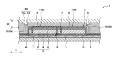
- FIG. 1 is a cross-sectional view of a solar cell module according to a first embodiment.
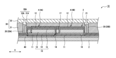
- FIG. 4 is a cross-sectional view of a solar cell module according to a second embodiment.
- FIG. 11 is a cross-sectional view of a solar cell module according to a third embodiment.
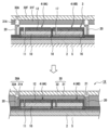
- 5A to 5C are diagrams for explaining an example of a method for manufacturing the solar cell module according to the first embodiment.
- 11A to 11C are diagrams for explaining an example of a method for manufacturing a solar cell module according to a second embodiment.
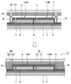
- 13A to 13C are diagrams for explaining an example of a method for manufacturing a solar cell module according to a third embodiment.
- FIG. 13 is a cross-sectional view of a solar cell module according to a fourth embodiment.
- FIG. 1 is a cross-sectional view of a solar cell module according to a first embodiment.
- FIG. 4 is a cross-sectional view of a solar cell module according to a second embodiment.
- FIG. 11 is
- FIG. 13 is a cross-sectional view of a solar cell module according to a fifth embodiment.
- FIG. 13 is a cross-sectional view of a solar cell module according to a sixth embodiment.
- FIG. 13 is a cross-sectional view of a solar cell module according to a seventh embodiment.
- FIG. 1 shows a schematic cross-sectional structure of a solar cell module 1 according to a first embodiment, cut in the X direction.
- a first direction along the surface of the substrate 2 is defined as the "X direction (shown in FIG. 1)," and a second direction along the surface of the substrate 2 and perpendicular to the X direction is defined as the "Y direction (direction perpendicular to the paper surface of FIG. 1).”
- the solar cell module 1 includes a substrate 2 and a cell 3 provided on the substrate 2.
- the cell 3 is composed of a plurality of unit cells 4 connected in series.
- Each unit cell 4 includes a photoelectric conversion layer 10, a first electrode layer 11, and a second electrode layer 12.
- the solar cell module 1 further includes an extraction electrode layer 20 and a sealing layer 30.
- the extraction electrode layer 20 is an electrode for extracting electrical energy from the cell 3 to the outside of the module, and is provided in an area that does not overlap with the photoelectric conversion layer 10 when the substrate 2 is viewed in a plan view.
- the sealing layer 30 is a layer that sandwiches the cell 3 together with the substrate 2 and prevents water vapor and oxygen from flowing into the module.
- the sealing layer 30 is provided so as to cover the cell 3 (photoelectric conversion layer 10, first electrode layer 11, second electrode layer 12) and the extraction electrode layer 20, and has an opening 30A in the area corresponding to the extraction electrode layer 20.
- the solar cell module 1 may include an inorganic film 40 provided on the substrate 2.
- the inorganic film 40 is interposed between the substrate 2 and the first electrode layer 11.
- the inorganic film 40 may be, for example, an inorganic film of the same type as the barrier layer of the second layer 32 described below.
- the extraction electrode layer 20 is exposed from the opening 30A of the sealing layer 30, and the peripheral portion of the extraction electrode layer 20 is covered by the sealing layer 30. That is, a portion of the surface 21 of the extraction electrode layer 20 facing the side opposite the substrate 2 is exposed from the opening 30A of the sealing layer 30, and the periphery of the exposed portion is covered by the sealing layer 30. In this case, water vapor and oxygen are effectively prevented from flowing into the module from around the extraction electrode layer 20.
- the substrate 2 may be a conductive substrate with an insulating layer formed on its surface, but preferably an insulating substrate is used.
- the substrate 2 is made of a material that is transparent to sunlight with a wavelength of 400 nm or more and 1000 nm or less, and has a low water vapor transmission rate.
- the substrate 2 may be a resin substrate or a glass substrate.
- the thickness of the substrate 2 is, for example, 0.02 mm or more and 3 mm or less. Since the solar cell module 1 has a support 5, it is also possible to use a resin film similar to the barrier film described below as the substrate 2.
- the solar cell module 1 includes a plurality of unit cells 4 connected in series.
- a plurality of unit cells 4 are arranged in the X direction and are continuous in the Y direction perpendicular to the X direction.
- the unit cells 4 in this embodiment are perovskite type cells, and include a first electrode layer 11 provided on the substrate 2, a photoelectric conversion layer 10 provided on the first electrode layer 11, and a second electrode layer 12 provided on the photoelectric conversion layer 10.
- At least one of the substrate 2 and the sealing layer 30 covering the surface of the cell 3 (each unit cell 4) has optical transparency.
- the sealing layer 30 is opaque, and the surface of the substrate 2 becomes the light receiving surface of the module.
- the photoelectric conversion layer 10 includes a light absorbing layer 13, an electron transport layer 14, and a hole transport layer 15, and has a laminated structure in which the electron transport layer 14 and the hole transport layer 15 are arranged to sandwich the light absorbing layer 13 from both sides.
- the electron transport layer 14, the light absorbing layer 13, and the hole transport layer 15 are arranged in this order from the substrate 2 side, except for a portion in which a groove described later is formed.
- the light absorbing layer 22 includes, for example, a perovskite compound represented by a composition formula ABX 3 (wherein A is a monovalent cation, B is a divalent cation, and X is a halogen anion).
- the electron transport layer 14 is made of an n-type semiconductor and is also called an n-layer. Examples of electron transport materials that make up the electron transport layer 14 include anatase-type titanium oxide and tin oxide.
- the hole transport layer 15 is made of a p-type semiconductor and is also called a p-layer.
- the hole transport layer 15 contains a hole transport material that has an oxidation-reduction site. Examples of hole transport materials that make up the hole transport layer 15 include 2,2',7,7'-tetrakis(N,N'-di-p-methoxyphenylamino)-9,9'-spirobifluorene (Spiro-OMeTAD).
- a in the above perovskite compound (ABX 3 ) is a monovalent cation represented by R 1 R 2 R 3 -N-H.
- R 1 and R 2 are H and R 3 is CH 3
- A is methylammonium (CH 3 NH 3 ).
- the functional groups R 1 , R 2 , and R 3 contain at least one element selected from carbon, hydrogen, nitrogen, and oxygen, for example.
- the functional groups R 1 , R 2 , and R 3 contain carbon atoms, the total number of carbon atoms in the functional groups R 1 , R 2 , and R 3 is preferably 4 or less.
- the functional groups R 1 , R 2 , and R 3 may contain a Group 1 element such as Rb or Cs.
- B in ABX 3 is a divalent cation.
- B is, for example, a divalent cation of a transition metal or a group 13 element, a group 14 element, or a group 15 element.
- Specific examples of B include Pb 2+ , Ge 2+ , and Sn 2+ .
- B may contain at least one element selected from Pb 2+ and Sn 2+ , and a part of Pb 2+ and Sn 2+ may be substituted with other elements. Examples of the substitution element include Bi, Sb, In, Ge, and Ni.
- X in ABX 3 is at least one element selected from Cl, Br, and I.
- Each of the A, M, and X sites may be occupied by multiple types of ions.
- Specific examples of perovskite compounds (ABX 3 ) include CH 3 NH 3 PbI 3 , CH 3 CH 2 NH 3 PbI 3 , NH 2 CHNH 2 PbI 3 , CH 3 NH 3 PbBr 3 , CH 3 NH 3 PbCl 3 , CsPbI 3 , and CsPbBr 3 .
- the light absorbing layer 13 made of CH 3 NH 3 PbI 3 is also called a PVSK element.
- the first electrode layer 11 and the second electrode layer 12 are preferably light-transmitting and do not block the entry of light into the photoelectric conversion layer 10.
- the light transmittance of each electrode layer is, for example, 85% or more in the wavelength range of 450 nm to 900 nm.
- the sheet resistance of each electrode layer is preferably 200 ⁇ / ⁇ or less, and may be 50 ⁇ / ⁇ or less.
- a suitable electrode layer is a transparent conductive layer composed of a transparent conductive oxide such as indium tin oxide (ITO) in which a metal oxide such as indium oxide or zinc oxide is doped with tungsten, tin, antimony, or the like.
- the thickness of the transparent conductive layer is, for example, 30 nm to 300 nm.
- Each electrode layer can be formed by a conventional method such as sputtering.
- unit cell 4A two unit cells 4 adjacent to each other in the X direction are shown, with the unit cell 4 on the left side referred to as "unit cell 4A" and the unit cell 4 on the right side referred to as "unit cell 4B".
- the number of unit cells 4 included in the solar cell module 1 is not particularly limited, and may be three or more.
- the second electrode layer 12 of unit cell 4A is electrically connected to the first electrode layer 11 of unit cell 4B.
- the second electrode layer 12 of unit cell 4B is electrically connected to the first electrode layer 11 of a third unit cell 4 adjacent to it in the X direction. In this way, a plurality of unit cells 4 are connected in series along the X direction.
- Grooves 16, 17, and 18 are formed by removing a portion of the layers that make up cell 3, and extend in the Y direction and are formed approximately parallel to each other.
- Each groove can be formed by a conventionally known scribing method or the like.
- Each groove width is, for example, 30 ⁇ m or more and 300 ⁇ m or less.
- Groove 17 is filled with a resin that makes up sealing layer 30 so that no voids are formed within the groove.
- the grooves 16 are grooves that divide the first electrode layer 11 of each unit cell 4.
- the grooves 17 divide the light absorbing layer 13, the hole transport layer 15, and the second electrode layer 12 of each unit cell 4. Note that the grooves 17 only need to divide the second electrode layer 12 of each unit cell 4, and the light absorbing layer 13 and the hole transport layer 15 do not have to be divided by the grooves 17.
- the unit cells 4 are partitioned by the grooves 16 and 17.
- the groove 18 is formed so as to penetrate the hole transport layer 15, the light absorption layer 13, and the electron transport layer 14 to expose the first electrode layer 11 of the unit cell 4B.
- the second electrode layer 12 of the unit cell 4A is formed in the groove 18. This electrically connects the first electrode layer 11 of the unit cell 4B to the second electrode layer 12 of the unit cell 4A.
- the groove 18 functions as a conductive path that connects multiple unit cells 4 in series.
- the cell 3 is manufactured, for example, by the following method.
- a first electrode layer 11 and an electron transport layer 14 are formed in this order on a substrate 2 .
- a portion of the first electrode layer 11 is laser scribed to form a groove 16 .
- On the electron transport layer 14, a light absorbing layer 13 and a hole transport layer 15 are formed in this order.
- the hole transport layer 15, the light absorption layer 13, and a portion of the electron transport layer 14 are subjected to a mechanical scribing process to form grooves 18.
- the second electrode layer 12 is formed on the hole transport layer 15. At this time, the second electrode layer 12 is formed in the groove 18, and the conductive path is formed.
- the second electrode layer 12, the hole transport layer 15, and a portion of the light absorbing layer 13 are subjected to a mechanical scribing process to form grooves 17.
- the light absorption layer 13, the electron transport layer 14, and the hole transport layer 15 can be formed, for example, by applying a solution in which the constituent materials of each layer are dissolved to the surface of the substrate 2.
- These layers may be formed by a meniscus coating method, a spin coating method, or a dispenser.
- the thickness of each layer is not particularly limited, but is, for example, 10 nm or more and 500 nm or less.
- the extraction electrode layer 20 has a structure in which metal layers are stacked, and is provided on the substrate 2 in an area that does not overlap with the photoelectric conversion layer 10 when the substrate 2 is viewed in a plan view. In other words, the extraction electrode layer 20 is provided in an area that does not overlap with the photoelectric conversion layer 10 in the thickness direction of the solar cell module 1.
- the extraction electrode layer 20 includes an extraction electrode layer 20A electrically connected to the first electrode layer 11 of the unit cell 4A, and an extraction electrode layer 20B electrically connected to the second electrode layer 12 of the unit cell 4B.
- the extraction electrode layer 20A is disposed at a first end in the X direction of the substrate 2, and the extraction electrode layer 20B is disposed at a second end in the X direction opposite to the first end.
- the metal layer constituting the extraction electrode layer 20 is composed of, for example, a metal such as aluminum, nickel, copper, or silver, or an alloy of these. Of these, it is preferable to use silver.
- the metal layer may have a single layer structure or a multi-layer structure including a layer of a different metal.
- An example of the thickness of the extraction electrode layer 20 is 10 ⁇ m or more and 100 ⁇ m or less.
- the extraction electrode layer 20 may be formed by printing, sputtering, vapor deposition, or the like, or may be formed by a plating method.
- the sealing layer 30 is a layer that covers the entire cell 3, and prevents water vapor and oxygen from flowing into the module.
- the sealing layer 30 may also have a function of capturing water vapor and the like.
- the sealing layer 30 covers the side surface of the extraction electrode layer 20 along the thickness direction.
- the extraction electrode layer 20 is an electrode for extracting the power generated in the cell 3 to the outside of the module, a part of the surface 21 of the extraction electrode layer 20 facing away from the substrate 2 is exposed and not covered by the sealing layer 30.
- An opening 30A is formed in the sealing layer 30 to expose a part of the surface 21 of the extraction electrode layer 20.
- the sealing layer 30 covers the peripheral portion of the surface 21 of the extraction electrode layer 20.
- the shape of the opening 30A of the sealing layer 30 is not particularly limited, but as an example, it is circular in plan view.
- the opening 30A of the sealing layer 30 is arranged so as to overlap with the surface 21 of the extraction electrode layer 20 in the thickness direction of the module, and the portion where the opening area is smallest is smaller than the surface 21. In this embodiment, the area of the opening 30A is smallest at the portion in contact with the surface 21.
- the sealing layer 30 can be a single-layer structure or a multi-layer structure having three or more layers, but in this embodiment, it has a two-layer structure including a first layer 31 and a second layer 32.
- the first layer 31 has a first opening 31A in a region corresponding to the extraction electrode layer 20.
- the second layer 32 is provided so as to cover the first layer 31, and has a second opening 32A in a region corresponding to the extraction electrode layer 20.
- the first opening 31A and the second opening 32A are arranged to overlap in the thickness direction of the module, forming an opening 30A in the sealing layer 30.
- the first layer 31 is filled in the groove 17 formed in the cell 3, between the cell 3 and the extraction electrode layer 20, etc., and adheres closely to the cell 3 and the extraction electrode layer 20. It is preferable that the first layer 31 adheres closely to the cell 3 without any gaps so that no gaps are formed between the cell 3 and the first layer 31. In this case, the inflow of water vapor and oxygen into the module is suppressed.
- the first layer 31 is preferably made of a resin with low water vapor and oxygen permeability.
- the first layer 31 may contain a moisture absorbing filler.
- the first layer 31, which has the function of capturing moisture, is also called a getter layer.
- the resin constituting the first layer 31 may be any resin that has low water vapor and oxygen permeability and good adhesion to the cells 3, and an example of a suitable resin is an olefin-based polymer.
- An olefin-based polymer is a polymer whose main constituent unit is an olefin-derived unit.
- the first layer 31 is, for example, a layer in which a moisture-absorbing filler is dispersed in an olefin-based polymer.
- the first layer 31 may contain other components other than the olefin-based polymer and the moisture-absorbing filler. Examples of other components include a tackifier, a curing accelerator, an antioxidant, a plasticizer, and a rubber component.
- the olefin polymer is preferably a copolymer of two or more kinds of olefins, or a copolymer of an olefin and a monomer other than an olefin, such as a non-conjugated diene or styrene.
- copolymers include ethylene-non-conjugated diene copolymer, ethylene-propylene copolymer, ethylene-propylene-non-conjugated diene copolymer, ethylene-butene copolymer, propylene-butene copolymer, propylene-butene-non-conjugated diene copolymer, styrene-isobutene copolymer, styrene-isobutene-styrene copolymer, isobutene-isoprene copolymer, etc.
- the olefin polymer preferably has a crosslinked structure, and is obtained by reacting a copolymer containing a first reactive functional group with a copolymer containing a second reactive functional group.
- the reactive functional groups can be selected from the group consisting of epoxy groups, carboxy groups, acid anhydride groups, amino groups, hydroxyl groups, and isocyanate groups, and are used in combinations that react with each other. Specific examples of combinations of reactive functional groups include epoxy groups and carboxy groups, epoxy groups and acid anhydride groups, and carboxy groups and acid anhydride groups.
- moisture-absorbing fillers examples include uncalcined hydrotalcite, semi-calcined hydrotalcite, calcined hydrotalcite, calcium oxide, magnesium oxide, calcined dolomite, calcium hydride, strontium oxide, aluminum oxide, barium oxide, molecular sieves, and silica.
- the thickness of the first layer 31 is, for example, 10 ⁇ m to 100 ⁇ m, and preferably 30 ⁇ m to 70 ⁇ m. If the thickness of the first layer 31 is within this range, good sealing performance and water vapor trapping performance can be ensured.
- the material constituting the first layer 31 is supplied in the form of a film during the manufacturing process of the solar cell module 1, and flows when heated, pressurized, or heated and pressurized, so that it adheres closely to the cells 3 without any gaps, and also fills the grooves of the cells 3.
- the second layer 32 is a layer with low water vapor and oxygen permeability, and is provided to cover the entire first layer 31, suppressing the inflow of water vapor and oxygen into the module.
- the second layer 32 is preferably composed of a resin film having a barrier layer.
- the resin film is composed mainly of resins such as olefin polymers such as polyethylene, polypropylene, and polyvinyl chloride, polyesters such as polyethylene terephthalate, polycarbonate, and polyimide.
- the barrier layer is preferably formed on the inner surface of the resin film, i.e., the surface facing the first layer 31. Examples of barrier layers include inorganic films such as silica vapor deposition films, silicon nitride films, and silicon oxide films.
- the thickness of the second layer 32 is, for example, 20 ⁇ m or more and 150 ⁇ m or less, and preferably 50 ⁇ m or more and 100 ⁇ m or less. Since the thickness of the barrier layer is thinner than that of the resin film, the thickness of the second layer 32 is substantially the same as the thickness of the resin film that constitutes the second layer 32. There is no particular limitation on the relationship between the thicknesses of the first layer 31 and the second layer 32.
- the first layer 31 and the second layer 32 are laminated in this order from the substrate 2 side as described above, and are arranged so that the first opening 31A and the second opening 32A overlap.
- the extraction electrode layer 20 has a portion of its surface 21 exposed from the opening 30A (first opening 31A and second opening 32A) of the sealing layer 30, but the surface 21 is located closer to the substrate 2 than the surface of the sealing layer 30 and is embedded in the sealing layer 30. In this embodiment, the surface 21 of the extraction electrode layer 20 is located closer to the substrate 2 than the interface between the first layer 31 and the second layer 32.
- the first layer 31 preferably covers the peripheral portion of the surface 21 of the extraction electrode layer 20 and adheres closely to the side surface along the thickness direction of the extraction electrode layer 20. In this case, the inflow of water vapor and oxygen into the module is more effectively suppressed.
- the first opening 31A of the first layer 31 is formed smaller than the second opening 32A of the second layer 32.
- the opening 30A of the sealing layer 30 formed by the first opening 31A and the second opening 32A may become gradually smaller as it approaches the surface 21 of the extraction electrode layer 20. In the example shown in FIG. 1, the first opening 31A gradually decreases in diameter toward the surface 21.
- the first layer 31 preferably covers the entire peripheral area of the surface 21. That is, the first layer 31 is in close contact with the surface 21 over the entire peripheral area of the surface 21 so as to surround the portion exposed from the first opening 31A of the surface 21. In this case, the effect of suppressing the inflow of water vapor and oxygen becomes more pronounced.
- the first layer 31 may be disposed over the entire circumference with a substantially constant width from the peripheral area of the surface 21.
- the first layer 31 covers, for example, an area of 10% to 50% of the area of the surface 21.
- the second opening 32A of the second layer 32 is formed to be larger than the surface 21.
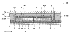
- FIG. 2 is a cross-sectional view of solar cell module 1X, which is a second embodiment
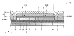
- FIG. 3 is a cross-sectional view of solar cell module 1Y, which is a third embodiment.
- solar cell modules 1X and 1Y are common to solar cell module 1 in that sealing layer 30 has a two-layer structure including first layer 31 and second layer 32, and surface 21 of extraction electrode layer 20 is located closer to substrate 2 than the interface between first layer 31 and second layer 32. That is, extraction electrode layer 20 is embedded in first layer 31. In this case as well, when substrate 2 is viewed in plan from the side on which photoelectric conversion layer 10 is provided, part of surface 21 of extraction electrode layer 20 is exposed from first opening 31A and second opening 32A.
- solar cell modules 1X and 1Y differ from solar cell module 1 in that the second opening 32A of the second layer 32 is smaller than the first opening 31A of the first layer 31.
- the first opening 31A is larger than the second opening 32A.
- the opening area on the outermost surface of solar cell module 1 is smaller, so the amount of water vapor and oxygen flowing into the opening can be reduced.
- the second opening 32A of the second layer 32 is formed smaller than the area of the surface 21 of the extraction electrode layer 20.
- the second layer 32 is disposed on the peripheral portion so as to cover the entire peripheral portion of the surface 21. Since the first layer 31 is interposed between the extraction electrode layer 20 and the second layer 32, the second layer 32 does not contact the surface 21.
- the opening area of the second opening 32A is preferably small enough to not interfere with the extraction of power from the extraction electrode layer 20, and is, for example, 90% or less of the area of the surface 21.
- the first opening 31A of the first layer 31 is formed to be larger than the surface 21, and the peripheral portion of the surface 21 is not covered by the first layer 31.
- the solar cell module 1Y shown in FIG. 3 like the solar cell module 1X, the second opening 32A of the second layer 32 is formed smaller than the area of the surface 21 of the extraction electrode layer 20, and the second layer 32 is disposed on the peripheral portion of the surface 21.
- the solar cell module 1Y differs from the solar cell module 1X in that the first opening 31A of the first layer 31 is formed smaller than the area of the surface 21, and the peripheral portion of the surface 21 is covered by the first layer 31. That is, the order is surface 21 > first opening 31A > second opening 32A, and the peripheral portion of the surface 21 is covered by the first layer 31 and the second layer 32. In this case, the effect of suppressing the inflow of water vapor and oxygen becomes more pronounced.
- FIG. 4 to 6 show the cross-sectional structure of a solar cell module during the manufacturing process, cut in the X direction.
- the manufacturing process of the solar cell modules 1, 1X, 1Y includes, for example, the following steps.
- the photoelectric conversion layer 10, the first electrode layer 11, the second electrode layer 12, and the extraction electrode layer 20 can be provided on the substrate 2 by a conventionally known method, as described above.
- FIGS. 4 to 6 are diagrams showing the process of providing the sealing layer 30, each illustrating a different formation method.
- a support 5 is used to support the substrate 2.
- the support 5 is made of a material that is thicker and more rigid than the substrate 2.
- the solar cell module is transported, for example, while placed on the support 5, and each layer is formed on the substrate 2.
- An adhesive layer for adhesion may be provided between the support 5 and the substrate 2.
- FIG 4 shows the manufacturing process of the solar cell module 1.
- the sealing layer 30 is placed on the second electrode layer 12 and the extraction electrode layer 20, a part of the sealing layer 30 is removed to form an opening 30A.
- the opening 30A is formed by a conventionally known scribing method or the like in a region of the sealing layer 30 that corresponds to the extraction electrode layer 20, i.e., a position that overlaps with the extraction electrode layer 20 in the thickness direction of the module.
- the opening 30A is formed so that the extraction electrode layer 20 is exposed through the opening 30A and the peripheral portion of the extraction electrode layer 20 is covered by the sealing layer 30.
- film 31F constituting first layer 31 is placed so as to cover second electrode layer 12 and extraction electrode layer 20, and film 32F constituting second layer 32 is placed on top of that.
- Each film 31F, 32F may be integrated in advance and then supplied onto substrate 2.
- Film 31F placed on substrate 2 is heated, pressurized, or heated and pressurized, thereby adhering film 31F to cell 3, etc.
- material constituting first layer 31 is also filled into groove 17.
- the opening 30A (first opening 31A of the first layer 31) of the sealing layer 30 is formed so that the opening area gradually becomes smaller closer to the surface 21 of the extraction electrode layer 20.
- the first layer 31 covers the entire periphery of the surface 21, but openings may be formed in each film 31F, 32F so that both the first layer 31 and the second layer 32 cover the periphery of the surface 21.
- each opening may be formed so that both the first opening 31A and the second opening 32A are smaller than the area of the surface 21.
- FIG. 5 shows the manufacturing process of the solar cell module 1X.
- a sealing layer 30 having an opening 30A is arranged on the second electrode layer 12 and the extraction electrode layer 20.
- the substrate 2 is viewed in plan from the side on which the photoelectric conversion layer 10 is provided, the extraction electrode layer 20 is exposed through the opening 30A, and the sealing layer 30 is arranged so that the peripheral portion of the extraction electrode layer 20 is covered. That is, in this manufacturing process, films 31F, 32F with openings formed in advance are arranged on the substrate 2. More specifically, the films 31F, 32F are arranged so that the extraction electrode layer 20, the first opening 31A, and the second opening 32A overlap in the thickness direction of the module.
- FIG. 5 shows the manufacturing process for solar cell module 1X, but solar cell modules 1 and 1Y can be manufactured in a similar manner.
- the second opening 32A of the second layer 32 is formed smaller than the first opening 31A of the first layer 31, and the surface 21 of the extraction electrode layer 20 ⁇ first opening 31A > second opening 32A, but the solar cell modules 1 and 1Y can be manufactured by changing the size of each opening.
- FIG. 6 shows the manufacturing process of solar cell module 1Y, but solar cell module 1X can be manufactured in a similar manner.
- a first layer 31 with a first opening 31A formed in advance is provided on the second electrode layer 12 and the extraction electrode layer 20, a second layer 32 is provided on the first layer 31, and then a second opening 32A is formed. That is, this manufacturing process includes the steps of providing a first layer 31 having a first opening 31A in a region corresponding to the extraction electrode layer 20, providing a second layer 32 on the first layer 31, and removing a portion of the second layer 32 to form the second opening 32A.
- the first layer 31 and the second layer 32 are provided and the second opening 32A is formed so that the extraction electrode layer 20 is exposed through the first opening 31A and the second opening 32A and the peripheral portion of the extraction electrode layer 20 is covered by at least one of the first layer 31 and the second layer 32.
- the film 31F is arranged so that the extraction electrode layer 20 and the first opening 31A overlap in the thickness direction of the module, and after the film 32F is laminated on the film 31F, the second opening 32A is formed at a position overlapping the first opening 31A.
- the surface 21 of the extraction electrode layer 20 is located closer to the substrate 2 than the surface of the sealing layer 30, and is embedded in the sealing layer 30.
- the surface 21 of the extraction electrode layer 20 is exposed from the opening 30A of the sealing layer 30. Meanwhile, the surface 21 of the extraction electrode layer 20 is not covered by the first layer 31 and the second layer 32.
- the configurations of the first to third embodiments can be selectively applied to the fourth to sixth embodiments. In this case, the effect of suppressing the inflow of water vapor and oxygen becomes more pronounced.
- the grooves 17 filled with the first layer 31 of the sealing layer 30 are formed so as to gradually widen the further away from the substrate 2.
- the grooves 17 are formed, for example, by removing parts of the photoelectric conversion layer 10, the hole transport layer 15, and the second electrode layer 12 (parts that overlap in the thickness direction of the module), and the opening formed in the hole transport layer 15 is larger than the opening formed in the photoelectric conversion layer 10. Furthermore, the opening in the second electrode layer 12 is larger than the opening in the hole transport layer 15.
- the solar cell module 50 has grooves 17 formed therein that gradually widen the further away from the substrate 2, and the first layer 31 is formed within the grooves 17.
- the grooves 17 may have a width that changes stepwise at the interface between the layers as shown in FIG. 7, or may continuously widen from the photoelectric conversion layer 10 toward the second electrode layer 12.
- the solar cell module 51 of the fifth embodiment fine irregularities are formed on the surface of the second electrode layer 12 that contacts the first layer 31 of the sealing layer 30.
- the contact area between the first layer 31 and the second electrode layer 12 is increased, and the adhesion between the first layer 31 and the second electrode layer 12 is improved.
- gaps are less likely to occur between the first layer 31 and the second electrode layer 12, and the inflow of water vapor and oxygen into the module is effectively suppressed.
- the irregularities may be formed only on the surface of the second electrode layer 12, in the example shown in FIG. 8, the irregularities are formed on the surface of the photoelectric conversion layer 10, and the hole transport layer 15 and the second electrode layer 12 are formed along the irregularities of the photoelectric conversion layer 10, thereby forming the irregularities on the surface of the second electrode layer 12.
- the arithmetic mean roughness Ra of the surface of the second electrode layer 12 is, for example, 1 nm or more and 100 nm or less. If the arithmetic mean roughness Ra is within this range, the effect of improving the adhesion between the first layer 31 and the second electrode layer 12 becomes more significant.
- the arithmetic mean roughness Ra of the surface of the second electrode layer 12 can be measured by cross-sectional TEM.
- the method of forming irregularities on the surface of the photoelectric conversion layer 10 is not particularly limited, but one example is a spin coating method.
- the solar cell module 52 of the sixth embodiment includes a spring electrode 60 as a wiring material electrically connected to the extraction electrode layer 20.
- the spring electrode 60 is disposed in the opening 30A of the sealing layer 30, and one axial end of the spring electrode 60 is in contact with the surface 21 of the extraction electrode layer 20.
- the other axial end of the spring electrode 60 protrudes from the opening 30A and is connected to an external device (not shown).
- the opening 30A may be filled with a sealant 61 that seals the gap between the sealing layer 30 and the spring electrode 60.
- the sealant 61 may be made of a material similar to that of the first layer 31.
- the thickness of the first layer 31 constituting the sealing layer 30 is reduced around the extraction electrode layer 20.
- the extraction electrode layer 20 thicker than the sealing layer 30 and enlarging the opening of the film constituting the first layer 31 to the extent that a gap is created between the extraction electrode layer 20 and the film, the film fills the gap and sinks into the substrate 2.
- the second layer 32 follows the first layer 31, and the surface of the second layer 32 is recessed. As a result, the surface 21 of the extraction electrode layer 20 and its vicinity protrude from the sealing layer 30.
- the sealing layer 30 adheres strongly to the side surface of the extraction electrode layer 20, making it difficult for a gap to form between the extraction electrode layer 20 and the sealing layer 30. As a result, the inflow of water vapor and oxygen into the module is effectively suppressed.
- the solar cell modules of the above embodiments can sufficiently prevent water vapor and oxygen from entering the module.
- the solar cell modules of the above embodiments have excellent sealing performance and can maintain good output performance for a long period of time.
- water vapor and oxygen are effectively prevented from entering the module from around the extraction electrode layer 20.
- the configurations of the first to third embodiments can be selectively applied to the fourth to sixth embodiments, in which case the effect of suppressing the inflow of water vapor and oxygen becomes more pronounced.
- at least one configuration selected from the group consisting of the widening shape of the groove 17 of the fourth embodiment, the surface irregularities of the second electrode layer 12 of the fifth embodiment, and the spring electrode 60 of the sixth embodiment may be applied to the solar cell modules 1, 1X, and 1Y.
- the sealing layer may also be supplied to the solar cell module manufacturing process in the form of a single film containing the barrier layer as an intermediate layer.
- the barrier layer is sandwiched between two resin films, for example.
- the resin film placed on the substrate 2 may be a film having the same function as the film constituting the first layer 31, and the resin film placed on the outside of the barrier layer may be a film having the same function as the film constituting the second layer 32.
Landscapes
- Chemical & Material Sciences (AREA)
- Engineering & Computer Science (AREA)
- Materials Engineering (AREA)
- Physics & Mathematics (AREA)
- Electromagnetism (AREA)
- Photovoltaic Devices (AREA)
Priority Applications (3)
| Application Number | Priority Date | Filing Date | Title |
|---|---|---|---|
| CN202380067840.7A CN119908190A (zh) | 2022-09-30 | 2023-09-01 | 太阳能电池模块及太阳能电池模块的制造方法 |
| EP23871738.3A EP4598314A4 (en) | 2022-09-30 | 2023-09-01 | SOLAR CELL MODULE AND SOLAR CELL MODULE MANUFACTURING METHOD |
| US19/089,947 US20250228058A1 (en) | 2022-09-30 | 2025-03-25 | Solar cell module and method for manufacturing solar cell module |
Applications Claiming Priority (2)
| Application Number | Priority Date | Filing Date | Title |
|---|---|---|---|
| JP2022158254A JP2024051878A (ja) | 2022-09-30 | 2022-09-30 | 太陽電池モジュールおよび太陽電池モジュールの製造方法 |
| JP2022-158254 | 2022-09-30 |
Related Child Applications (1)
| Application Number | Title | Priority Date | Filing Date |
|---|---|---|---|
| US19/089,947 Continuation US20250228058A1 (en) | 2022-09-30 | 2025-03-25 | Solar cell module and method for manufacturing solar cell module |
Publications (1)
| Publication Number | Publication Date |
|---|---|
| WO2024070498A1 true WO2024070498A1 (ja) | 2024-04-04 |
Family
ID=90477210
Family Applications (1)
| Application Number | Title | Priority Date | Filing Date |
|---|---|---|---|
| PCT/JP2023/032073 Ceased WO2024070498A1 (ja) | 2022-09-30 | 2023-09-01 | 太陽電池モジュールおよび太陽電池モジュールの製造方法 |
Country Status (5)
| Country | Link |
|---|---|
| US (1) | US20250228058A1 (https=) |
| EP (1) | EP4598314A4 (https=) |
| JP (1) | JP2024051878A (https=) |
| CN (1) | CN119908190A (https=) |
| WO (1) | WO2024070498A1 (https=) |
Citations (9)
| Publication number | Priority date | Publication date | Assignee | Title |
|---|---|---|---|---|
| JP2005243440A (ja) * | 2004-02-26 | 2005-09-08 | Hitachi Maxell Ltd | 光電変換素子 |
| JP2009188211A (ja) | 2008-02-06 | 2009-08-20 | Sanyo Electric Co Ltd | 太陽電池モジュール |
| CN205542904U (zh) * | 2016-02-26 | 2016-08-31 | 景德镇陶瓷学院 | 一种用于钙钛矿太阳能电池的非接触式封装器件 |
| JP2016174151A (ja) | 2015-03-16 | 2016-09-29 | 積水化学工業株式会社 | 太陽電池 |
| WO2018052032A1 (ja) * | 2016-09-14 | 2018-03-22 | 積水化学工業株式会社 | フレキシブル太陽電池 |
| JP2018113437A (ja) * | 2017-01-12 | 2018-07-19 | 株式会社リコー | 光電変換素子及び太陽電池 |
| JP2018147956A (ja) * | 2017-03-02 | 2018-09-20 | 積水化学工業株式会社 | 太陽電池 |
| WO2019065430A1 (ja) * | 2017-09-29 | 2019-04-04 | 積水化学工業株式会社 | 太陽電池モジュール、および太陽電池モジュールの製造方法 |
| CN112582549A (zh) * | 2020-12-28 | 2021-03-30 | 厦门大学 | 一种薄型无溶剂钙钛矿太阳能电池封装方法 |
Family Cites Families (4)
| Publication number | Priority date | Publication date | Assignee | Title |
|---|---|---|---|---|
| TWI553892B (zh) * | 2015-12-31 | 2016-10-11 | 台灣中油股份有限公司 | 具鈣鈦礦施體層之太陽能電池模組 |
| US10319533B2 (en) * | 2017-01-12 | 2019-06-11 | Ricoh Company, Ltd. | Photoelectric conversion element and solar cell |
| US12100731B2 (en) * | 2020-06-26 | 2024-09-24 | Intel Corporation | Crystalline bottom electrode for perovskite capacitors and methods of fabrication |
| WO2022066707A1 (en) * | 2020-09-22 | 2022-03-31 | Caelux Corporation | Methods and devices for integrated tandem solar module fabrication |
-
2022
- 2022-09-30 JP JP2022158254A patent/JP2024051878A/ja active Pending
-
2023
- 2023-09-01 WO PCT/JP2023/032073 patent/WO2024070498A1/ja not_active Ceased
- 2023-09-01 EP EP23871738.3A patent/EP4598314A4/en active Pending
- 2023-09-01 CN CN202380067840.7A patent/CN119908190A/zh active Pending
-
2025
- 2025-03-25 US US19/089,947 patent/US20250228058A1/en active Pending
Patent Citations (9)
| Publication number | Priority date | Publication date | Assignee | Title |
|---|---|---|---|---|
| JP2005243440A (ja) * | 2004-02-26 | 2005-09-08 | Hitachi Maxell Ltd | 光電変換素子 |
| JP2009188211A (ja) | 2008-02-06 | 2009-08-20 | Sanyo Electric Co Ltd | 太陽電池モジュール |
| JP2016174151A (ja) | 2015-03-16 | 2016-09-29 | 積水化学工業株式会社 | 太陽電池 |
| CN205542904U (zh) * | 2016-02-26 | 2016-08-31 | 景德镇陶瓷学院 | 一种用于钙钛矿太阳能电池的非接触式封装器件 |
| WO2018052032A1 (ja) * | 2016-09-14 | 2018-03-22 | 積水化学工業株式会社 | フレキシブル太陽電池 |
| JP2018113437A (ja) * | 2017-01-12 | 2018-07-19 | 株式会社リコー | 光電変換素子及び太陽電池 |
| JP2018147956A (ja) * | 2017-03-02 | 2018-09-20 | 積水化学工業株式会社 | 太陽電池 |
| WO2019065430A1 (ja) * | 2017-09-29 | 2019-04-04 | 積水化学工業株式会社 | 太陽電池モジュール、および太陽電池モジュールの製造方法 |
| CN112582549A (zh) * | 2020-12-28 | 2021-03-30 | 厦门大学 | 一种薄型无溶剂钙钛矿太阳能电池封装方法 |
Non-Patent Citations (1)
| Title |
|---|
| See also references of EP4598314A4 |
Also Published As
| Publication number | Publication date |
|---|---|
| US20250228058A1 (en) | 2025-07-10 |
| CN119908190A (zh) | 2025-04-29 |
| EP4598314A4 (en) | 2026-01-21 |
| EP4598314A1 (en) | 2025-08-06 |
| JP2024051878A (ja) | 2024-04-11 |
Similar Documents
| Publication | Publication Date | Title |
|---|---|---|
| JP6640174B2 (ja) | 太陽電池及びその製造方法 | |
| JP6050409B2 (ja) | 太陽電池 | |
| JP6396374B2 (ja) | 太陽電池 | |
| US20180033899A1 (en) | Solar cell | |
| US8809676B2 (en) | Thin film solar cell and method of manufacturing the same | |
| JP2019021913A (ja) | 太陽電池モジュール | |
| US20250072199A1 (en) | Solar cell module and method for manufacturing solar cell module | |
| JP2012015269A (ja) | 太陽電池モジュール | |
| KR20110107171A (ko) | 태양광 발전장치 및 이의 제조방법 | |
| US20250294917A1 (en) | Solar cell module | |
| US20190378939A1 (en) | Solar cell and manufacturing method therefor | |
| JP2009099883A (ja) | 薄膜太陽電池モジュール | |
| WO2024070498A1 (ja) | 太陽電池モジュールおよび太陽電池モジュールの製造方法 | |
| JP2013077749A (ja) | 太陽電池モジュール | |
| US9087953B2 (en) | Solar cell module and method for manufacturing the same | |
| US9076900B2 (en) | Solar cell module and solar cell | |
| KR101349429B1 (ko) | 태양광 발전장치 | |
| US20150027532A1 (en) | Solar cell, solar cell module and method of manufacturing solar cell | |
| US20220077412A1 (en) | Solar cell module | |
| JP2013527622A (ja) | 太陽電池モジュールおよびそのための製造方法 | |
| JP7631573B1 (ja) | 太陽電池モジュールおよび太陽電池モジュールの製造方法 | |
| US9972728B2 (en) | Solar cell, solar cell module, and method for manufacturing solar cell | |
| KR101283302B1 (ko) | 태양전지 및 이의 제조방법 | |
| CN121604598A (zh) | 太阳能电池及其制备方法、用电设备 | |
| WO2025047722A1 (ja) | 光電変換素子、光電変換モジュール及び光電変換システム |
Legal Events
| Date | Code | Title | Description |
|---|---|---|---|
| 121 | Ep: the epo has been informed by wipo that ep was designated in this application |
Ref document number: 23871738 Country of ref document: EP Kind code of ref document: A1 |
|
| WWE | Wipo information: entry into national phase |
Ref document number: 202380067840.7 Country of ref document: CN |
|
| WWP | Wipo information: published in national office |
Ref document number: 202380067840.7 Country of ref document: CN |
|
| WWE | Wipo information: entry into national phase |
Ref document number: 2023871738 Country of ref document: EP |
|
| NENP | Non-entry into the national phase |
Ref country code: DE |
|
| ENP | Entry into the national phase |
Ref document number: 2023871738 Country of ref document: EP Effective date: 20250430 |
|
| WWP | Wipo information: published in national office |
Ref document number: 2023871738 Country of ref document: EP |