WO2024070367A1 - 過給機 - Google Patents
過給機 Download PDFInfo
- Publication number
- WO2024070367A1 WO2024070367A1 PCT/JP2023/030596 JP2023030596W WO2024070367A1 WO 2024070367 A1 WO2024070367 A1 WO 2024070367A1 JP 2023030596 W JP2023030596 W JP 2023030596W WO 2024070367 A1 WO2024070367 A1 WO 2024070367A1
- Authority
- WO
- WIPO (PCT)
- Prior art keywords
- coil
- bus bar
- temperature sensor
- sensing element
- temperature
- Prior art date
- Legal status (The legal status is an assumption and is not a legal conclusion. Google has not performed a legal analysis and makes no representation as to the accuracy of the status listed.)
- Ceased
Links
Images


Classifications
-
- H—ELECTRICITY
- H02—GENERATION; CONVERSION OR DISTRIBUTION OF ELECTRIC POWER
- H02K—DYNAMO-ELECTRIC MACHINES
- H02K7/00—Arrangements for handling mechanical energy structurally associated with dynamo-electric machines, e.g. structural association with mechanical driving motors or auxiliary dynamo-electric machines
- H02K7/14—Structural association with mechanical loads, e.g. with hand-held machine tools or fans
-
- F—MECHANICAL ENGINEERING; LIGHTING; HEATING; WEAPONS; BLASTING
- F02—COMBUSTION ENGINES; HOT-GAS OR COMBUSTION-PRODUCT ENGINE PLANTS
- F02B—INTERNAL-COMBUSTION PISTON ENGINES; COMBUSTION ENGINES IN GENERAL
- F02B39/00—Component parts, details, or accessories relating to, driven charging or scavenging pumps, not provided for in groups F02B33/00 - F02B37/00
- F02B39/02—Drives of pumps; Varying pump drive gear ratio
- F02B39/08—Non-mechanical drives, e.g. fluid drives having variable gear ratio
- F02B39/10—Non-mechanical drives, e.g. fluid drives having variable gear ratio electric
-
- H—ELECTRICITY
- H02—GENERATION; CONVERSION OR DISTRIBUTION OF ELECTRIC POWER
- H02K—DYNAMO-ELECTRIC MACHINES
- H02K11/00—Structural association of dynamo-electric machines with electric components or with devices for shielding, monitoring or protection
- H02K11/20—Structural association of dynamo-electric machines with electric components or with devices for shielding, monitoring or protection for measuring, monitoring, testing, protecting or switching
- H02K11/25—Devices for sensing temperature, or actuated thereby
-
- H—ELECTRICITY
- H02—GENERATION; CONVERSION OR DISTRIBUTION OF ELECTRIC POWER
- H02K—DYNAMO-ELECTRIC MACHINES
- H02K2203/00—Specific aspects not provided for in the other groups of this subclass relating to the windings
- H02K2203/09—Machines characterised by wiring elements other than wires, e.g. bus rings, for connecting the winding terminations
-
- H—ELECTRICITY
- H02—GENERATION; CONVERSION OR DISTRIBUTION OF ELECTRIC POWER
- H02K—DYNAMO-ELECTRIC MACHINES
- H02K2203/00—Specific aspects not provided for in the other groups of this subclass relating to the windings
- H02K2203/12—Machines characterised by the bobbins for supporting the windings
-
- H—ELECTRICITY
- H02—GENERATION; CONVERSION OR DISTRIBUTION OF ELECTRIC POWER
- H02K—DYNAMO-ELECTRIC MACHINES
- H02K2203/00—Specific aspects not provided for in the other groups of this subclass relating to the windings
- H02K2203/15—Machines characterised by cable windings, e.g. high-voltage cables, ribbon cables
-
- H—ELECTRICITY
- H02—GENERATION; CONVERSION OR DISTRIBUTION OF ELECTRIC POWER
- H02K—DYNAMO-ELECTRIC MACHINES
- H02K3/00—Details of windings
- H02K3/46—Fastening of windings on the stator or rotor structure
- H02K3/52—Fastening salient pole windings or connections thereto
- H02K3/521—Fastening salient pole windings or connections thereto applicable to stators only
- H02K3/522—Fastening salient pole windings or connections thereto applicable to stators only for generally annular cores with salient poles
-
- Y—GENERAL TAGGING OF NEW TECHNOLOGICAL DEVELOPMENTS; GENERAL TAGGING OF CROSS-SECTIONAL TECHNOLOGIES SPANNING OVER SEVERAL SECTIONS OF THE IPC; TECHNICAL SUBJECTS COVERED BY FORMER USPC CROSS-REFERENCE ART COLLECTIONS [XRACs] AND DIGESTS
- Y02—TECHNOLOGIES OR APPLICATIONS FOR MITIGATION OR ADAPTATION AGAINST CLIMATE CHANGE
- Y02T—CLIMATE CHANGE MITIGATION TECHNOLOGIES RELATED TO TRANSPORTATION
- Y02T10/00—Road transport of goods or passengers
- Y02T10/10—Internal combustion engine [ICE] based vehicles
- Y02T10/12—Improving ICE efficiencies
Definitions
- This disclosure relates to a turbocharger.
- the thermistor is attached to the coil end of the stator using a specified mounting fixture.
- installation space for the thermistor installation space for the mounting fixture itself is also required, which reduces the space inside the stator and hinders the miniaturization of the stator. It is also possible to adhere the thermistor inside the stator using an adhesive, but it may be difficult to stably fix the thermistor due to variations in adhesive strength, etc.
- This disclosure describes a turbocharger in which the thermistor is mounted on the stator of the motor, reducing the installation space required and allowing the thermistor to be stably fixed.
- the gist of this disclosure is as follows:
- a supercharger comprising an assist motor unit having a rotor provided on a rotating shaft connecting a turbine impeller and a compressor impeller, and a stator provided around the rotor, the stator having a stator core, an insulator provided around the stator core, a coil wound around the insulator, a bus bar connected to one of the coil ends located on the inner periphery of both ends of the coil, a temperature measuring unit having a temperature sensor unit that detects the temperature of the coil, and a signal cable drawn from the temperature sensor unit, the temperature sensor unit being inserted in the direction of the rotation axis of the assist motor unit into an element pocket provided in the insulator, and the signal cable being drawn from the temperature sensor unit in the opposite direction to the insertion direction of the temperature sensor unit into the element pocket, and extending so as to cross the temperature sensor unit side of the bus bar as viewed from the direction of the rotation axis.
- the turbocharger disclosed herein reduces the installation space required by mounting the thermistor on the motor stator, and the thermistor is stably fixed.
- FIG. 2 is a cross-sectional view of a turbocharger according to the embodiment.
- 4A to 4C are exploded views showing main parts of a stator.
- 3A to 3C are exploded views showing the main parts of the stator, following FIG. 2.
- FIG. 2 is a circuit diagram of a stator.
- FIG. 2A is a perspective view showing an electromagnet assembly in which a thermistor is installed
- FIG. 2B is a perspective view showing a state in which a coil has been removed from this electromagnet assembly.
- 6 is a cross-sectional view taken along line VI-VI in FIG. 1 is an enlarged view of the vicinity of a thermistor in the stator immediately before it is fixed by resin molding, as viewed in the axial direction from the compressor side.
- FIG. 1 is an enlarged view of the vicinity of a thermistor in the stator immediately before it is fixed by resin molding, as viewed in the axial direction from the compressor side.
- the gist of this disclosure is as follows: [1] to [6].
- a supercharger comprising an assist motor unit having a rotor provided on a rotating shaft connecting a turbine impeller and a compressor impeller, and a stator provided around the rotor, the stator having a stator core, an insulator provided around the stator core, a coil wound around the insulator, a bus bar connected to one of the coil ends located on the inner periphery of both ends of the coil, a temperature measuring unit having a temperature sensor unit that detects the temperature of the coil, and a signal cable drawn from the temperature sensor unit, the temperature sensor unit being inserted in the direction of the rotation axis of the assist motor unit into an element pocket provided in the insulator, and the signal cable being drawn from the temperature sensor unit in the opposite direction to the insertion direction of the temperature sensor unit into the element pocket, and extending so as to cross the temperature sensor unit side of the bus bar as viewed from the direction of the rotation axis.
- a turbocharger in which a plurality of electromagnet assemblies each having the stator core, the insulator, and the coil are arranged in the circumferential direction, the bus bar extends in the radial direction at a position between two adjacent electromagnet assemblies as viewed from the axial direction, and both of the two signal cables drawn out from the temperature sensor unit are drawn out from the temperature sensor unit in the direction opposite to the insertion direction of the temperature sensor unit into the element pocket, extend across the bus bar as viewed from the rotation axis direction, and pass through the temperature sensor unit side of the bus bar.
- a turbocharger according to any one of [1] to [3], in which the coil end extends in the axial direction and is positioned circumferentially adjacent to the temperature sensing element portion in the element pocket.
- a turbocharger according to any one of [1] to [4], in which a molding resin is filled between the temperature-sensing element and the coil.
- a supercharger according to any one of [1] to [5], in which a gap is formed in the element pocket to expose a portion of the temperature-sensing element portion within the element pocket, and the coil and the temperature-sensing element portion are in close proximity to each other through the gap.
- FIG. 1 is a cross-sectional view taken along a line including the rotation axis H of the turbocharger 1.
- axial direction when the terms “axial direction”, “radial direction”, and “circumferential direction” are used simply, they refer to the axial direction, radial direction, and circumferential direction, respectively, of the rotating shaft 14 described below.
- outer peripheral side/inner peripheral side when the terms “outer peripheral side/inner peripheral side” are used simply, they refer to the outer side/inner side in the radial direction of the rotating shaft 14.
- the turbocharger 1 is applied to an internal combustion engine of a vehicle or the like.
- the turbocharger 1 includes a turbine 2 and a compressor 3.
- the turbine 2 includes a turbine housing 4 and a turbine wheel 6 housed in the turbine housing 4.
- the turbine housing 4 has a scroll passage 16 that extends in the circumferential direction around the turbine wheel 6.
- the compressor 3 includes a compressor housing 5 and a compressor wheel 7 housed in the compressor housing 5.
- the compressor housing 5 has a scroll passage 17 that extends in the circumferential direction around the compressor wheel 7.
- the turbine wheel 6 is provided at one end of the rotating shaft 14, and the compressor wheel 7 is provided at the other end of the rotating shaft 14.
- a bearing housing 13 is provided between the turbine housing 4 and the compressor housing 5.
- the rotating shaft 14 is rotatably supported by the bearing housing 13 via a bearing 15, and the rotating shaft 14, the turbine wheel 6, and the compressor wheel 7 rotate around the rotation axis H as an integrated rotating body 12.
- the turbine housing 4 is provided with an exhaust gas inlet (not shown) and an exhaust gas outlet 10. Exhaust gas discharged from an internal combustion engine (not shown) flows into the turbine housing 4 through the exhaust gas inlet. The exhaust gas then flows into the turbine wheel 6 through the scroll passage 16, causing the turbine wheel 6 to rotate. The exhaust gas then flows out of the turbine housing 4 through the exhaust gas outlet 10.
- the compressor housing 5 is provided with an intake port 9 and a discharge port (not shown).
- the compressor wheel 7 rotates via the rotating shaft 14.
- the rotating compressor wheel 7 draws in outside air through the intake port 9. This air passes through the compressor wheel 7 and scroll passage 17, where it is compressed and discharged from the discharge port.
- the compressed air discharged from the discharge port is supplied to the internal combustion engine described above.
- the turbocharger 1 is equipped with a motor 21 (assist motor section).
- a motor 21 assist motor section.
- the motor 21 is, for example, a brushless AC motor, and includes a rotor 25, which is a rotor, and a stator 27, which is a fixed part.
- the vehicle's battery can be used as the driving source of the motor 21.
- the motor 21 may generate regenerative power using the rotational energy of the rotating body 12.
- the motor 21 has characteristics that can handle high-speed rotation of the rotating shaft 14 (for example, 100,000 to 200,000 rpm).
- the rotor 25 is disposed between the bearing 15 and the compressor impeller 7 in the axial direction.
- the rotor 25 is fixed to the rotating shaft 14 and can rotate together with the rotating shaft 14.
- the stator 27 is accommodated in the bearing housing 13 and disposed so as to surround the rotor 25 in the circumferential direction.
- the stator 27 includes a plurality of coils and an iron core (not shown). When a current is supplied to the coils and the stator 27 generates a magnetic field, a circumferential force acts on the permanent magnets 29 of the rotor 25 due to this magnetic field, and as a result, a torque is applied to the rotating shaft 14.
- FIGS 2(a) to 2(c) and 3(a) to 3(c) are exploded views of the main parts of the stator 27.
- the direction perpendicular to the paper surface of Figures 2 and 3 is the axial direction
- the back side of the paper surface is the turbine 2 side
- the front side of the paper surface is the compressor 3 side.
- the parts shown in Figure 2(b) are arranged on the front side of the parts shown in Figure 2(c)
- the parts shown in Figure 2(a) are arranged on the front side of the paper surface.
- the main body 30 has six electromagnet assemblies 31 arranged to surround the rotor 25 (Fig. 1). These electromagnet assemblies 31 are housed, for example, in a circular metal casing (not shown) and are arranged at equal intervals in the circumferential direction at a pitch of 60°.
- the electromagnet assembly 31 has a core teeth portion 33 extending radially inward and a coil 35 wound around the core teeth portion 33.
- the coil 35 is made of a pair of round wires, and the coil 35 is wound in a concentrated manner with 5.5 turns.
- the coil end 36 located on the radial inside is drawn out from the core teeth portion 33 to the compressor side (the front side of the paper in Fig. 2), and the coil end 37 located on the radial outside is drawn out from the core teeth portion 33 to the turbine side (the back side of the paper in Fig. 2).
- the stator 27 is a three-phase, six-slot stator, and the six coils 35 are composed of a first U-phase coil 35u1, a second U-phase coil 35u2, a first V-phase coil 35v1, a second V-phase coil 35v2, a first W-phase coil 35w1, and a second W-phase coil 35w2.
- these coils are arranged clockwise in FIG. 2 in the order of the first V-phase coil 35v1, the second W-phase coil 35w2, the first U-phase coil 35u1, the second V-phase coil 35v2, the first W-phase coil 35w1, and the second U-phase coil 35u2.
- an SPM one-pole pair motor rotor is used as the rotor 25 for such a stator 27.
- the neutral bus bar 39 shown in FIG. 2B is installed on the compressor side of the main body 30.
- the neutral bus bar 39 includes an annular portion 41 installed on the peripheral portion of the main body 30, and three connection bus bars 43u2, 43v2, and 43w2 extending from the annular portion 41 in a cantilever manner toward the inner periphery.
- the connection bus bar 43u2 is connected to the coil end 36 of the second U-phase coil 35u2
- the connection bus bar 43v2 is connected to the coil end 36 of the second V-phase coil 35v2
- the connection bus bar 43w2 is connected to the coil end 36 of the second W-phase coil 35w2.
- the connection bus bars 43u2, 43v2, and 43w2 are arranged at equal intervals in the circumferential direction at a pitch of 120°.
- connection bus bar 43u2 extends radially between the second U-phase coil 35u2 and the first W-phase coil 35w1 when viewed from the axial direction.
- connection bus bar 43v2 extends radially between the second V-phase coil 35v2 and the first U-phase coil 35u1 when viewed from the axial direction.
- connection bus bar 43w2 extends radially between the second W-phase coil 35w2 and the first V-phase coil 35v1 when viewed from the axial direction.
- three lead line bus bars 45u1, 45v1, 45w1 shown in FIG. 2(a) are installed on the compressor side of the neutral point bus bar 39.
- One end of the lead line bus bar 45u1 is connected to the coil end 36 of the first U-phase coil 35u1
- one end of the lead line bus bar 45v1 is connected to the coil end 36 of the first V-phase coil 35v
- one end of the lead line bus bar 45w1 is connected to the coil end 36 of the first W-phase coil 35w1.
- the other ends of the three lead line bus bars 45u1, 45v1, 45w1 constitute input terminals 47u, 47v, 47w that accept current input from the outside, and each protrudes outward from the main body 30 and is exposed to the outside of the stator 27.
- the lead-out bus bar 45u1 connects the input terminal 47u and the coil end 36 of the first U-phase coil 35u1 via an arc portion along the periphery of the main body 30.
- the coil end 36 side portion of the lead-out bus bar 45u1 extends radially between the first U-phase coil 35u1 and the second W-phase coil 35w2 when viewed from the axial direction.
- the lead-out bus bar 45v1 connects the input terminal 47v and the coil end 36 of the first V-phase coil 35v1 in a generally linear manner.
- the coil end 36 side portion of the lead-out bus bar 45v1 extends radially between the first V-phase coil 35v1 and the second U-phase coil 35u2 when viewed from the axial direction.
- the lead-out bus bar 45w1 connects the input terminal 47w and the coil end 36 of the first W-phase coil 35w1 via an arc portion along the periphery of the main body 30.
- the portion of the lead wire bus bar 45w1 on the coil end 36 side extends radially between the first W-phase coil 35w1 and the second V-phase coil 35v2 when viewed in the axial direction.
- crossover bus bars 49u, 49v, and 49w are installed on the turbine side of the main body 30 in a stacked manner.
- the crossover bus bar 49u connects the coil end 37 of the first U-phase coil 35u1 to the coil end 37 of the second U-phase coil 35u2 via a semicircular arc portion along the periphery of the main body 30.
- the crossover bus bar 49v connects the coil end 37 of the first V-phase coil 35v1 to the coil end 37 of the second V-phase coil 35v2 via a semicircular arc portion along the periphery of the main body 30.
- the crossover bus bar 49w connects the coil end 37 of the first W-phase coil 35w1 to the coil end 37 of the second W-phase coil 35w2 via a semicircular arc portion along the periphery of the main body 30.
- the neutral bus bar 39, the lead bus bars 45u1, 45v1, 45w1, and the crossover bus bars 49u, 49v, 49w are each made of a copper plate material formed integrally, and each extends in a plane generally perpendicular to the axial direction.
- an electrical insulating layer is interposed between each bus bar and the electromagnet assembly 31 and between each bus bar.
- the neutral bus bar 39, the lead bus bars 45u1, 45v1, 45w1, and the ring-shaped insulating resin part 42 (see FIG. 7) in which these bus bars are embedded are molded integrally.
- a part of the insulating resin part 42 enters between the bus bars and functions as the electrical insulating layer.
- the above-mentioned group of parts shown in FIG. 2 and FIG. 3 constitutes a stator 27 with two Y-connected wires in series as shown in the circuit diagram of FIG. 4.
- the stator 27 is equipped with a thermistor 51.
- the thermistor 51 is attached to the core teeth portion 33 of one of the electromagnet assemblies 31.
- the thermistor 51 (see FIG. 5(b)) comprises a temperature sensing element portion 51a having an elongated rectangular parallelepiped shape, two signal cables 51b extending from one longitudinal end face of the temperature sensing element portion 51a, and crimp terminals 51c provided at the end of each signal cable 51b for connection to the outside.
- the whole is resin molded and fixed, and the input terminals 47u, 47v, 47w and the two crimp terminals 51c are exposed to the outside from the molded resin 50.
- the resin mold can be processed by transfer molding, potting, or the like.
- FIG. 5(a) is a perspective view showing one of the six electromagnet assemblies 31 described above, in which a thermistor 51 is installed.
- FIG. 5(b) is a perspective view showing the state in which the coil 35 has been removed from this electromagnet assembly 31.
- FIG. 6 is a cross-sectional view taken along the line VI-VI in FIG. 5(b).
- the electromagnet assembly 31 includes a stator core 53, which is an iron core, and a resin insulator 55 arranged to cover the surface of the stator core 53.
- the stator core 53 and the insulator 55 are integrally formed, for example, by insert molding.
- the insulator 55 functions as a guide around which the coil 35 is wound, and also functions as an electrical insulator between the stator core 53 and the coil 35.
- the periphery of the stator core 53 is completely covered by the insulator 55, and the coil 35 is wound around this insulator 55.
- the insulator 55 has a pocket 57 for installing the thermistor 51.
- the pocket 57 is formed by cutting out a part of the inner peripheral end of the insulator 55.
- the temperature sensor 51a is inserted into the pocket 57 in the axial direction from the compressor side to the turbine side.
- the temperature sensor 51a abuts against the pocket bottom surface 57a on the turbine side and is stored in an orientation with its longitudinal direction facing the axial direction.
- the displacement of the temperature sensor 51a toward the turbine side is restricted by the pocket bottom surface 57a.
- the pocket 57 has wall-like portions 57b and 57c that restrict the radial displacement of the temperature sensor 51a, and a wall surface 57d and a restricting portion 57e that restrict the circumferential displacement of the temperature sensor 51a. Therefore, before the resin molding process is performed, the radial and circumferential displacements of the temperature sensor 51a are restricted.
- a radial gap 57f is provided between the restricting portion 57e and the wall-like portion 57b, and within the width of the gap 57f, the temperature sensor 51a is exposed in the circumferential direction over the entire longitudinal direction.
- the coil end 35a of the coil 35 on the coil end 36 side passes through the turbine side of the pocket bottom surface 57a, bends toward the compressor side, and extends axially along the above-mentioned gap 57f.
- This coil end 35a is adjacent to the temperature sensor part 51a in the circumferential direction through the gap 57f. In other words, the coil end 35a is close to the temperature sensor part 51a through the gap 57f.
- the coil end 35a may also be in contact with the temperature sensor part 51a.
- the regulating portion 57e may also function as a guide for the coil end 35a.
- the above describes the configuration of the electromagnet assembly 31 ( Figures 5 and 6) in which the thermistor 51 is installed.
- the other electromagnet assemblies 31 in which the thermistor 51 is not installed differ only in that they do not have a pocket 57, and have a similar configuration in other respects, so duplicated explanations will be omitted.
- pockets 57 may be formed in all six electromagnet assemblies 31, including the other electromagnet assemblies 31 in which the thermistor 51 is not installed. In this case, it is preferable in that parts can be standardized between all electromagnet assemblies 31.
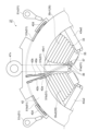
- FIG. 7 is an enlarged view of the vicinity of the thermistor 51 in the stator 27 immediately before the resin molding process is performed, viewed in the axial direction from the compressor side.
- the thermistor 51 is installed in the electromagnet assembly 31 in which the first V-phase coil 35v1 is configured.
- the temperature sensor 51a of the thermistor 51 is stored in a pocket 57 of an insulator 55 of the electromagnet assembly 31.
- the temperature sensor 51a is located slightly offset in the circumferential direction from the lead line bus bar 45v1.
- the temperature sensor 51a is positioned slightly offset to the right from the lead line bus bar 45v1.
- the compressor-side end face of the temperature sensor 51a is positioned closer to the turbine than the lead line bus bar 45v1.
- the two signal cables 51b of the thermistor 51 are drawn out from the compressor-side end face of the temperature sensor unit 51a and extend across the position of the lead-line bus bar 45v1 when viewed from the axial direction. At the portion where the signal cables 51b cross the lead-line bus bar 45v1, the two signal cables 51b pass through the turbine side of the lead-line bus bar 45v1.
- the further tip sides of the two signal cables 51b are fitted into two grooves 42a provided in the insulating resin part 42.
- the grooves 42a are formed on the compressor-side end face of the insulating resin part 42 and are located to the left of the lead-line bus bar 45v1 in FIG. 7.
- the grooves 42a also have claws 42b for holding the signal cables 51b in the grooves 42a. By fitting into the grooves 42a having such claws 42b, the signal cables 51b do not easily float up from the insulating resin part 42 to the compressor side.
- the further tips of the two signal cables 51b are pulled out to the outer circumferential surface of the insulating resin part 42 through insertion holes provided at the outer circumferential ends of the grooves 42a.
- the signal cables 51b extend in opposite directions on the outer circumferential surface of the insulating resin part 42.
- a cable holding part 42d that holds the signal cables 51b is provided on the outer circumferential surface of the insulating resin part 42.
- the cable holding part 42d has a groove with a tab, similar to the groove 42a, and the signal cables 51b are fitted into this groove to be held.
- the cable holding portion 42d also guides the bending of the tip of the signal cable 51b.
- the tip of the signal cable 51b is held and guided by the cable holding portion 42d and bent outward from the outer circumferential surface, and a crimp terminal 51c is provided at the tip.
- the vicinity of the bent portion of the signal cable 51b held by the cable holding portion 42d is covered in advance with a heat shrink tube.
- This heat shrink tube covering increases the rigidity of the signal cable 51b near the bent portion, and the bent shape of the bent portion is maintained by the rigidity of the signal cable 51b.
- the position of the crimp terminal 51c is maintained at a position slightly outside the cable holding portion 42d by the rigidity of the signal cable 51b. This position is adjusted to match the position of the external plug to which the crimp terminal 51c is bolted, improving the workability when bolting the crimp terminal 51c to the external plug.
- the temperature sensor 51a is stored and temporarily fixed in the pocket 57, and the signal cable 51b is routed, and then the resin molding process described above is carried out. Through this resin molding process, the temperature sensor 51a and the signal cable 51b of the thermistor 51 are embedded and permanently fixed in the molded resin 50 ( Figure 2).
- the signal cable 51b it is not essential that the signal cable 51b be fixed to the insulating resin part 42 by the cable holding part 42d as described above. In other words, the signal cable 51b does not necessarily need to be fixed inside the housing of the turbocharger 1.
- the insulating resin part 42 may be omitted.
- the thermistor 51 may have a connector (not shown) of a predetermined structure instead of the crimp terminal 51c, and may be connected to the outside via the connector.
- the thermistor 51 is not temporarily fixed in place before the resin molding process is performed, there is a risk that the position of the thermistor 51 may shift due to external forces generated during assembly or resin molding.
- the presence of a pocket 57 that stores the temperature sensor portion 51a of the thermistor 51 ensures that the temperature sensor portion 51a is temporarily fixed to the tip of the core teeth portion 33 before the resin molding process is performed.
- the temperature sensor unit 51a can be displaced axially toward the compressor side relative to the pocket 57.
- the signal cable 51b drawn from the temperature sensor unit 51a to the compressor side crosses the lead line bus bar 45v1 when viewed from the axial direction, and at the portion where it crosses the lead line bus bar 45v1, it passes closer to the temperature sensor unit 51a than the lead line bus bar 45v1.
- the lead line bus bar 45v1 prevents the signal cable 51b from displacing toward the compressor side. Accordingly, it is also difficult for the temperature sensor unit 51a to displace toward the compressor side, and the temperature sensor unit 51a is prevented from moving out of the pocket 57. Therefore, even when an external force generated during assembly or resin molding is applied, the temperature sensor unit 51a is securely held within the pocket 57, and there is little possibility of misalignment.
- the pocket 57 for temporarily fixing the temperature sensor unit 51a in this manner is formed by cutting out a portion of the end of the inner circumference side of the insulator 55, and no separate mounting fixture or the like is required to fix the temperature sensor unit 51a.
- the existing drawer bus bar 45v1 is used to prevent the temperature sensor unit 51a from slipping out of the pocket 57, so no separate mounting fixture or the like is required. Therefore, the installation space can be reduced compared to when a separate mounting fixture is used to attach the temperature sensor unit 51a.
- the work is simplified and manufacturing costs are reduced compared to attaching the temperature sensor unit 51a using a separate mounting fixture.
- the temperature sensor unit 51a were attached using adhesive or the like, there is a risk that the temporary fixation of the temperature sensor unit 51a may not be stable due to variations in adhesive strength.
- the stator 27 of this embodiment the temperature sensor unit 51a is temporarily fixed more stably and the work is simplified. Furthermore, since no time is required for the adhesive to harden, the tact time is reduced, and manufacturing costs are reduced.
- the signal cable 51b does not easily float up from the insulating resin part 42 toward the compressor even when it is subjected to external forces generated during assembly or resin molding. Therefore, the position of the signal cable 51b is reliably maintained until it is fixed by the resin molding process, and the situation in which a part of the signal cable 51b is exposed to the outside of the molded resin 50 is suppressed.
- the inner circumference of the stator 27 is prone to becoming hot due to reasons such as being far from the cooling water passage (not shown) arranged on the outside of the stator 27 and being close to the rotating rotor 25. Therefore, it is preferable that the temperature sensing element 51a of the thermistor 51 is installed on the inner circumference side of the stator 27. In contrast, the pocket 57 is provided at the tip of the core teeth portion 33, so that the temperature sensing element 51a can be arranged on the inner circumference side of the stator 27.
- a molded resin 50 is formed on the stator 27 by a resin molding process, and the molded resin 50 is also filled between the temperature sensor unit 51a and the coil 35. Therefore, the heat of the coil 35 is transferred to the temperature sensor unit 51a through the molded resin 50, and the temperature sensor unit 51a can detect the heat of the coil 35 to be managed.
- the temperature sensing element 51a of the thermistor 51 is placed close to the coil 35.
- the coil end 35a extends in the axial direction at a position circumferentially adjacent to the pocket 57. Therefore, the temperature sensing element 51a can be placed close to the coil end 35a in the circumferential direction, and the temperature of the coil 35 can be detected with good sensitivity.
- the aforementioned gap 57f is formed in the pocket 57, and the coil end 35a and the temperature sensing element 51a are close to each other through the gap 57f.
- the coil end 35a may also be in contact with the temperature sensing element 51a. Therefore, this gap 57f contributes to the temperature sensing element 51a detecting the temperature of the coil 35 as directly as possible.
- the back side of the paper in Figures 2 and 3 is the turbine side and the front side of the paper is the compressor side, but in this case the turbine side and the compressor side may be reversed.
- the temperature sensor unit 51a is installed in the electromagnet assembly 31 that constitutes the first V-phase coil 35v1, but the temperature sensor unit 51a may be installed in any of the six electromagnet assemblies 31.
- the bus bar across which the signal cable 51b crosses may be any of the lead line bus bars 45u1, 45v1, 45w1 and the connection bus bars 43u2, 43v2, 43w2, and may be determined according to the position of the electromagnet assembly 31 on which the temperature sensor unit 51a is installed.
- a thermistor 51 is installed in one of the six electromagnet assemblies 31 of the stator 27, but, for example, a thermistor 51 may be installed in each of multiple electromagnet assemblies 31, or a total of six thermistors 51 may be installed in each of all the electromagnet assemblies 31.
- This disclosure includes at least the following:
- An assist motor unit having a rotor provided on a rotating shaft that connects a turbine impeller and a compressor impeller, and a stator provided around the rotor,
- the stator includes: A stator core; an insulator provided around the stator core; A coil wound around the insulator; a bus bar connected to one of the coil ends located on the inner periphery side of both ends of the coil; a temperature measuring unit having a temperature sensing element unit that detects the temperature of the coil and a signal cable that is drawn out from the temperature sensing element unit;
- the temperature sensing element unit is the assist motor unit is inserted in a rotation axis direction into an element pocket provided in the insulator,
- the signal cable includes: The temperature sensor is pulled out from the temperature sensor unit in a direction opposite to the direction in which the temperature sensor unit is inserted into the element pocket, the turbocharger extending across the temperature sensing element side of the bus bar as viewed from the rotation axis direction.
- the bus bar extends radially inward from an insulating material present on the outer periphery side of the coil end and is connected to the coil end,
- a plurality of electromagnet assemblies each having the stator core, the insulator, and the coil are arranged in a circumferential direction, the bus bar extends radially between two adjacent electromagnet assemblies when viewed in the axial direction,
- the two signal cables drawn out from the temperature sensing element unit are both
- the temperature sensor is pulled out from the temperature sensor unit in a direction opposite to the direction in which the temperature sensor unit is inserted into the element pocket,
- the turbocharger according to claim 1 or 2 wherein the cooling fan extends across the bus bar when viewed from the rotation axis direction and passes through the temperature sensing element portion side of the bus bar.
- a turbocharger according to any one of [1] to [3], in which the coil end extends in the axial direction and is positioned circumferentially adjacent to the temperature sensing element portion in the element pocket.
- a turbocharger according to any one of [1] to [4], in which a molding resin is filled between the temperature-sensing element and the coil.
- a supercharger according to any one of [1] to [5], in which a gap is formed in the element pocket to expose a portion of the temperature-sensing element portion within the element pocket, and the coil and the temperature-sensing element portion are in close proximity to each other through the gap.
Landscapes
- Engineering & Computer Science (AREA)
- Power Engineering (AREA)
- Microelectronics & Electronic Packaging (AREA)
- Chemical & Material Sciences (AREA)
- Combustion & Propulsion (AREA)
- Mechanical Engineering (AREA)
- General Engineering & Computer Science (AREA)
- Supercharger (AREA)
Abstract
Description
前記ステータは、
ステータコアと、
前記ステータコアの周囲に設けられたインシュレータと、
前記インシュレータの周囲に巻き付けられたコイルと、
前記コイルの両端部のうち内周側に位置する一方のコイル端部に接続されるバスバと、
前記コイルの温度を検知する感温素子部と、前記感温素子部から引き出された信号ケーブルと、を有する温度計測部と、を有し、
前記感温素子部は、
前記インシュレータに設けられた素子用ポケットに対し前記アシスト用モータ部の回転軸線方向に挿入されており、
前記信号ケーブルは、
前記素子用ポケットへの前記感温素子部の挿入方向とは反対方向に前記感温素子部から引き出され、
前記回転軸線方向から見て前記バスバの前記感温素子部側を横切るように延びている、過給機。
前記信号ケーブルのうち、前記バスバを横切る部分と、前記ステータの外部に引き出されるケーブル端部と、の間の部分が、前記絶縁材に形成された溝に嵌め込まれている、〔1〕に記載の過給機。
前記バスバは、軸方向から見て隣接する2つの前記電磁石組立体の間の位置で径方向に延び、
前記感温素子部から引き出された2本の前記信号ケーブルが、両方とも、
前記素子用ポケットへの前記感温素子部の挿入方向とは反対方向に前記感温素子部から引き出され、
前記回転軸線方向から見て前記バスバを横切るように延び、前記バスバの前記感温素子部側を通過している、〔1〕又は〔2〕に記載の過給機。
6 タービン翼車
7 コンプレッサ翼車
14 回転軸
21 モータ(アシスト用モータ部)
25 ロータ
27 ステータ
31 電磁石組立体
35 コイル
35a コイル端部
42 絶縁樹脂部(絶縁材)
42a 溝
43u2 接続バスバ
43v2 接続バスバ
43w2 接続バスバ
45u1 引出線バスバ
45v1 引出線バスバ
45w1 引出線バスバ
50 モールド樹脂
51 サーミスタ(温度計測部)
51a 感温素子部
51b 信号ケーブル
53 ステータコア
55 インシュレータ
57 ポケット(素子用ポケット)
57f 隙間
H 回転軸線
Claims (6)
- タービンインペラとコンプレッサインペラとを連結する回転軸上に設けられるロータと、当該ロータの周囲に設けられたステータと、を有するアシスト用モータ部を備え、
前記ステータは、
ステータコアと、
前記ステータコアの周囲に設けられたインシュレータと、
前記インシュレータの周囲に巻き付けられたコイルと、
前記コイルの両端部のうち内周側に位置する一方のコイル端部に接続されるバスバと、
前記コイルの温度を検知する感温素子部と、前記感温素子部から引き出された信号ケーブルと、を有する温度計測部と、を有し、
前記感温素子部は、
前記インシュレータに設けられた素子用ポケットに対し前記アシスト用モータ部の回転軸線方向に挿入されており、
前記信号ケーブルは、
前記素子用ポケットへの前記感温素子部の挿入方向とは反対方向に前記感温素子部から引き出され、
前記回転軸線方向から見て前記バスバの前記感温素子部側を横切るように延びている、過給機。 - 前記バスバは、前記コイル端部よりも外周側に存在する絶縁材から径方向に内周側に延び出して前記コイル端部に接続されており、
前記信号ケーブルのうち、前記バスバを横切る部分と、前記ステータの外部に引き出されるケーブル端部と、の間の部分が、前記絶縁材に形成された溝に嵌め込まれている、請求項1に記載の過給機。 - 前記ステータコアと前記インシュレータと前記コイルとを有する電磁石組立体が周方向に複数配列されており、
前記バスバは、軸方向から見て隣接する2つの前記電磁石組立体の間の位置で径方向に延び、
前記感温素子部から引き出された2本の前記信号ケーブルが、両方とも、
前記素子用ポケットへの前記感温素子部の挿入方向とは反対方向に前記感温素子部から引き出され、
前記回転軸線方向から見て前記バスバを横切るように延び、前記バスバの前記感温素子部側を通過している、請求項1に記載の過給機。 - 前記コイル端部は、軸方向に延在しており、前記素子用ポケット内の前記感温素子部に対して周方向に隣接して位置する、請求項1に記載の過給機。
- 前記感温素子部と前記コイルとの間には充填されたモールド樹脂が存在する、請求項1に記載の過給機。
- 前記素子用ポケットには当該素子用ポケット内の前記感温素子部の一部を露出させる隙間が形成されており、当該隙間を通じて前記コイルと前記感温素子部とが近接している、請求項1に記載の過給機。
Priority Applications (4)
| Application Number | Priority Date | Filing Date | Title |
|---|---|---|---|
| DE112023003218.1T DE112023003218T5 (de) | 2022-09-29 | 2023-08-24 | Aufladeeinrichtung |
| CN202380059600.2A CN119731914A (zh) | 2022-09-29 | 2023-08-24 | 增压器 |
| JP2024549887A JPWO2024070367A1 (ja) | 2022-09-29 | 2023-08-24 | |
| US19/058,015 US20250233490A1 (en) | 2022-09-29 | 2025-02-20 | Turbocharger with insulator |
Applications Claiming Priority (2)
| Application Number | Priority Date | Filing Date | Title |
|---|---|---|---|
| JP2022-156036 | 2022-09-29 | ||
| JP2022156036 | 2022-09-29 |
Related Child Applications (1)
| Application Number | Title | Priority Date | Filing Date |
|---|---|---|---|
| US19/058,015 Continuation US20250233490A1 (en) | 2022-09-29 | 2025-02-20 | Turbocharger with insulator |
Publications (1)
| Publication Number | Publication Date |
|---|---|
| WO2024070367A1 true WO2024070367A1 (ja) | 2024-04-04 |
Family
ID=90477013
Family Applications (1)
| Application Number | Title | Priority Date | Filing Date |
|---|---|---|---|
| PCT/JP2023/030596 Ceased WO2024070367A1 (ja) | 2022-09-29 | 2023-08-24 | 過給機 |
Country Status (5)
| Country | Link |
|---|---|
| US (1) | US20250233490A1 (ja) |
| JP (1) | JPWO2024070367A1 (ja) |
| CN (1) | CN119731914A (ja) |
| DE (1) | DE112023003218T5 (ja) |
| WO (1) | WO2024070367A1 (ja) |
Cited By (1)
| Publication number | Priority date | Publication date | Assignee | Title |
|---|---|---|---|---|
| EP4686048A1 (en) * | 2024-07-25 | 2026-01-28 | Nanjing Chervon Industry Co., Ltd. | Power tool and electric motor |
Citations (6)
| Publication number | Priority date | Publication date | Assignee | Title |
|---|---|---|---|---|
| JP2007282336A (ja) * | 2006-04-04 | 2007-10-25 | Toyota Motor Corp | 検出部材の固定構造および電動過給機 |
| JP2013116011A (ja) * | 2011-11-30 | 2013-06-10 | Hitachi Automotive Systems Ltd | 機電一体型駆動装置 |
| WO2014132359A1 (ja) * | 2013-02-27 | 2014-09-04 | 三菱電機株式会社 | 回転電機 |
| JP2018085784A (ja) * | 2016-11-21 | 2018-05-31 | トヨタ自動車株式会社 | コイルの温度検出器 |
| JP2019097261A (ja) * | 2017-11-20 | 2019-06-20 | 株式会社ミツバ | ブラシレスモータ |
| JP2022120283A (ja) * | 2021-02-05 | 2022-08-18 | 三菱電機株式会社 | インシュレータ及び固定子 |
-
2023
- 2023-08-24 CN CN202380059600.2A patent/CN119731914A/zh active Pending
- 2023-08-24 WO PCT/JP2023/030596 patent/WO2024070367A1/ja not_active Ceased
- 2023-08-24 DE DE112023003218.1T patent/DE112023003218T5/de active Pending
- 2023-08-24 JP JP2024549887A patent/JPWO2024070367A1/ja active Pending
-
2025
- 2025-02-20 US US19/058,015 patent/US20250233490A1/en active Pending
Patent Citations (6)
| Publication number | Priority date | Publication date | Assignee | Title |
|---|---|---|---|---|
| JP2007282336A (ja) * | 2006-04-04 | 2007-10-25 | Toyota Motor Corp | 検出部材の固定構造および電動過給機 |
| JP2013116011A (ja) * | 2011-11-30 | 2013-06-10 | Hitachi Automotive Systems Ltd | 機電一体型駆動装置 |
| WO2014132359A1 (ja) * | 2013-02-27 | 2014-09-04 | 三菱電機株式会社 | 回転電機 |
| JP2018085784A (ja) * | 2016-11-21 | 2018-05-31 | トヨタ自動車株式会社 | コイルの温度検出器 |
| JP2019097261A (ja) * | 2017-11-20 | 2019-06-20 | 株式会社ミツバ | ブラシレスモータ |
| JP2022120283A (ja) * | 2021-02-05 | 2022-08-18 | 三菱電機株式会社 | インシュレータ及び固定子 |
Cited By (1)
| Publication number | Priority date | Publication date | Assignee | Title |
|---|---|---|---|---|
| EP4686048A1 (en) * | 2024-07-25 | 2026-01-28 | Nanjing Chervon Industry Co., Ltd. | Power tool and electric motor |
Also Published As
| Publication number | Publication date |
|---|---|
| US20250233490A1 (en) | 2025-07-17 |
| CN119731914A (zh) | 2025-03-28 |
| DE112023003218T5 (de) | 2025-06-12 |
| JPWO2024070367A1 (ja) | 2024-04-04 |
Similar Documents
| Publication | Publication Date | Title |
|---|---|---|
| US7652402B2 (en) | Brushless motor | |
| US6683397B2 (en) | Electric machine having at least one magnetic field detector | |
| JP5212680B2 (ja) | モータ | |
| US6002185A (en) | Molded motor | |
| CN103812275B (zh) | 具备旋转检测器的驱动单元 | |
| CN111295823B (zh) | 电动机及涡轮压缩机 | |
| KR102090830B1 (ko) | 전동기 및 공기 조화 장치 | |
| US8860267B2 (en) | Connector flange for an electric machine with stator windings | |
| CN101399481A (zh) | 车辆用发电机 | |
| CN109980882B (zh) | 旋转变压器定子 | |
| JP2009118614A (ja) | ブラシレスモータ | |
| JP2017188981A (ja) | ステータ、その製造方法、およびブラシレスモータ | |
| EP3790170A1 (en) | Rotating machine and insulator | |
| CN111699616B (zh) | 马达 | |
| JP2018121389A (ja) | 回転電機のステータ | |
| WO2007116956A1 (ja) | 検出部材の固定構造および電動過給機 | |
| JP5891999B2 (ja) | 回転電機 | |
| WO2024070367A1 (ja) | 過給機 | |
| CN119519220A (zh) | 电动压缩机 | |
| JP2018033197A (ja) | インバータ一体形回転電機 | |
| EP1757785B1 (en) | Supercharger with electric motor | |
| CN116896177A (zh) | 定子及使用该定子的旋转电机 | |
| CN114389409A (zh) | 旋转电机 | |
| CN219717958U (zh) | 一种电机定子及无刷电机 | |
| US20260012055A1 (en) | Electric motor |
Legal Events
| Date | Code | Title | Description |
|---|---|---|---|
| 121 | Ep: the epo has been informed by wipo that ep was designated in this application |
Ref document number: 23871608 Country of ref document: EP Kind code of ref document: A1 |
|
| WWE | Wipo information: entry into national phase |
Ref document number: 202380059600.2 Country of ref document: CN |
|
| WWE | Wipo information: entry into national phase |
Ref document number: 2024549887 Country of ref document: JP |
|
| WWE | Wipo information: entry into national phase |
Ref document number: 112023003218 Country of ref document: DE |
|
| WWP | Wipo information: published in national office |
Ref document number: 202380059600.2 Country of ref document: CN |
|
| WWP | Wipo information: published in national office |
Ref document number: 112023003218 Country of ref document: DE |
|
| 122 | Ep: pct application non-entry in european phase |
Ref document number: 23871608 Country of ref document: EP Kind code of ref document: A1 |