WO2024070115A1 - 撮像装置 - Google Patents
撮像装置 Download PDFInfo
- Publication number
- WO2024070115A1 WO2024070115A1 PCT/JP2023/024904 JP2023024904W WO2024070115A1 WO 2024070115 A1 WO2024070115 A1 WO 2024070115A1 JP 2023024904 W JP2023024904 W JP 2023024904W WO 2024070115 A1 WO2024070115 A1 WO 2024070115A1
- Authority
- WO
- WIPO (PCT)
- Prior art keywords
- pixel
- signal
- row
- pixels
- output
- Prior art date
Links
- 238000003384 imaging method Methods 0.000 title claims abstract description 103
- 238000006243 chemical reaction Methods 0.000 claims abstract description 55
- 239000011159 matrix material Substances 0.000 claims abstract description 5
- 101100421142 Mus musculus Selenon gene Proteins 0.000 description 46
- 230000000875 corresponding effect Effects 0.000 description 35
- 238000009825 accumulation Methods 0.000 description 21
- 230000003321 amplification Effects 0.000 description 17
- 238000003199 nucleic acid amplification method Methods 0.000 description 17
- 239000004065 semiconductor Substances 0.000 description 14
- 238000000034 method Methods 0.000 description 12
- 238000010586 diagram Methods 0.000 description 9
- 230000002093 peripheral effect Effects 0.000 description 9
- 239000000758 substrate Substances 0.000 description 9
- 230000000694 effects Effects 0.000 description 7
- 230000006870 function Effects 0.000 description 6
- 230000001276 controlling effect Effects 0.000 description 4
- 230000005669 field effect Effects 0.000 description 4
- 239000000463 material Substances 0.000 description 4
- 230000008569 process Effects 0.000 description 4
- 239000002184 metal Substances 0.000 description 3
- 229910052751 metal Inorganic materials 0.000 description 3
- 239000000203 mixture Substances 0.000 description 3
- 230000009467 reduction Effects 0.000 description 3
- 230000000903 blocking effect Effects 0.000 description 2
- 238000004364 calculation method Methods 0.000 description 2
- 230000008859 change Effects 0.000 description 2
- 238000004590 computer program Methods 0.000 description 2
- 239000004020 conductor Substances 0.000 description 2
- 230000014509 gene expression Effects 0.000 description 2
- 239000012212 insulator Substances 0.000 description 2
- 229910044991 metal oxide Inorganic materials 0.000 description 2
- 150000004706 metal oxides Chemical class 0.000 description 2
- 238000005096 rolling process Methods 0.000 description 2
- 230000001629 suppression Effects 0.000 description 2
- 101100202849 Drosophila melanogaster sel gene Proteins 0.000 description 1
- 239000003990 capacitor Substances 0.000 description 1
- 239000003086 colorant Substances 0.000 description 1
- 230000000295 complement effect Effects 0.000 description 1
- 230000002596 correlated effect Effects 0.000 description 1
- 230000001066 destructive effect Effects 0.000 description 1
- 238000009792 diffusion process Methods 0.000 description 1
- 238000012986 modification Methods 0.000 description 1
- 230000004048 modification Effects 0.000 description 1
- 230000011514 reflex Effects 0.000 description 1
- 230000000717 retained effect Effects 0.000 description 1
- 238000005070 sampling Methods 0.000 description 1
Images


Classifications
-
- H—ELECTRICITY
- H04—ELECTRIC COMMUNICATION TECHNIQUE
- H04N—PICTORIAL COMMUNICATION, e.g. TELEVISION
- H04N25/00—Circuitry of solid-state image sensors [SSIS]; Control thereof
- H04N25/40—Extracting pixel data from image sensors by controlling scanning circuits, e.g. by modifying the number of pixels sampled or to be sampled
- H04N25/46—Extracting pixel data from image sensors by controlling scanning circuits, e.g. by modifying the number of pixels sampled or to be sampled by combining or binning pixels
-
- H—ELECTRICITY
- H04—ELECTRIC COMMUNICATION TECHNIQUE
- H04N—PICTORIAL COMMUNICATION, e.g. TELEVISION
- H04N25/00—Circuitry of solid-state image sensors [SSIS]; Control thereof
- H04N25/60—Noise processing, e.g. detecting, correcting, reducing or removing noise
- H04N25/65—Noise processing, e.g. detecting, correcting, reducing or removing noise applied to reset noise, e.g. KTC noise related to CMOS structures by techniques other than CDS
Definitions
- This disclosure relates to an imaging device.
- CCD Charge Coupled Device
- CMOS Complementary Metal Oxide Semiconductor
- Patent Document 1 discloses an imaging device that forms a feedback path for each pixel in the imaging area and cancels reset noise through negative feedback.
- Patent document 2 discloses an imaging device with a high-speed pixel mixing function.
- An imaging device includes a plurality of pixels arranged in a matrix, signal lines provided for each column of the plurality of pixels, and a control circuit, each of the plurality of pixels including a photoelectric conversion unit that converts light into a signal charge, and the control circuit causes the plurality of pixels to output to the signal lines a pixel signal corresponding to the amount of the signal charge accumulated in the pixel and a reference signal after the pixel is reset, and during a first period during which a first pixel arranged in a first row outputs the pixel signal, the control circuit also causes a second pixel arranged in the first column in which the first pixel is arranged and arranged in a second row different from the first row to output the pixel signal, and causes the second pixel to output the pixel signal again after the first period and before resetting.
- FIG. 1 is a schematic diagram showing a configuration of an imaging device according to a first embodiment.
- FIG. 2 is a diagram showing a circuit configuration of the imaging device according to the first embodiment.
- FIG. 3 is a diagram showing a circuit configuration of a pixel in the imaging device according to the first embodiment.
- FIG. 4 is a timing chart of a first operation example of the imaging device according to the first embodiment.
- FIG. 5 is a timing chart of an operation example 2 of the imaging device according to the first embodiment.
- FIG. 6 is a timing chart of an operation example 3 of the imaging device according to the first embodiment.
- FIG. 7 is a timing chart of an operation example 4 of the imaging device according to the first embodiment.
- FIG. 8 is a diagram showing a circuit configuration of an imaging device according to the second embodiment.
- FIG. 9 is a timing chart of an example of the operation of the imaging device according to the second embodiment.
- Japanese Patent Application Laid-Open No. 2006-133693 discloses a technique for reducing reset noise by negative feedback. However, there is a demand for further noise reduction in imaging devices.
- the inventors focused on noise caused by an amplifier transistor that outputs a signal corresponding to the amount of signal charge generated by photoelectric conversion.
- Examples of noise caused by amplifier transistors include 1/f noise and thermal noise.
- the inventors investigated ways to reduce this noise, and arrived at the configuration disclosed herein.
- the imaging device includes a plurality of pixels arranged in a matrix, signal lines provided for each column of the plurality of pixels, and a control circuit, each of the plurality of pixels including a photoelectric conversion unit that converts light into a signal charge, and the control circuit causes the plurality of pixels to output to the signal lines a pixel signal corresponding to the amount of the signal charge accumulated in the pixel and a reference signal after the pixel is reset, and during a first period during which a first pixel arranged in a first row outputs the pixel signal, the control circuit also causes a second pixel arranged in the first column in which the first pixel is arranged and arranged in a second row different from the first row to output the pixel signal, and causes the second pixel to output the pixel signal again after the first period and before resetting.
- pixel signals from two rows of pixels, the first row and the second row are output simultaneously to the signal line and mixed.
- the effective gate width of the amplification transistor is doubled, and the mutual conductance gm of the amplification transistor is ⁇ 2 times.
- random noise caused by an amplification transistor is proportional to 1/gm. Therefore, low noise can be achieved by outputting pixel signals from two rows of pixels to the signal line simultaneously.
- the settling time is also proportional to 1/gm. Therefore, high-speed driving can be achieved by outputting pixel signals from two rows of pixels to the signal line simultaneously.
- an imaging device is the imaging device according to the first aspect, in which the control circuit resets the first pixel after causing it to output the pixel signal, and causes it to output the reference signal after the reset.
- the first pixel can continuously output the pixel signal and the reference signal, making it possible to perform signal processing using the pixel signal and the reference signal with a simple circuit configuration.
- an imaging device is the imaging device according to the first or second aspect, further comprising a signal processing circuit, and the signal processing circuit generates image data based on the pixel signals output by the first pixel and the second pixel during the first period and the reference signal output by the first pixel.
- image data can be generated using pixel signals that are a mixture of pixel signals from two rows of pixels, making it possible to generate image data with reduced noise.
- an imaging device is the imaging device according to the first aspect, in which the control circuit causes the first pixel to output the reference signal, accumulate the signal charge, and then output the pixel signal.
- the pixel signal of the first pixel is superimposed with reset noise equal to the previously output reference signal, so by subtracting the reference signal from the pixel signal, the effects of the reset noise can be removed, achieving even lower noise.
- an imaging device is an imaging device according to the first or fourth aspect, further comprising a signal processing circuit, and the signal processing circuit generates image data based on the reference signal output by the first pixel, the reference signal output by the second pixel, and the pixel signals output by the first pixel and the second pixel during the first period.
- image data can be generated using a pixel signal that is a mixture of pixel signals from two rows of pixels and a reference signal from two rows of pixels. Therefore, the effect of reset noise can be eliminated from the pixel signal that is a mixture of pixel signals from two rows of pixels by using the reference signal from two rows of pixels, achieving even lower noise.
- an imaging device is the imaging device according to the fifth aspect, further comprising a memory that stores a signal corresponding to the reference signal.
- an imaging device is an imaging device according to any one of the first to sixth aspects, in which the control circuit also outputs the pixel signal to a third pixel arranged in the first column and arranged in a third row different from the first row and the second row during the first period, and outputs the pixel signal to the third pixel again after the first period and before resetting.
- pixel signals from three rows of pixels, the first row, second row, and third row are simultaneously output to the signal line and mixed.
- the effective gate width of the amplification transistor becomes three times, and the mutual conductance gm of the amplification transistor becomes ⁇ 3 times. This makes it possible to achieve even lower noise and faster driving.
- an imaging device is an imaging device according to any one of the first to seventh aspects, further comprising a switch connected between the signal line provided in the first column and the signal line provided in a second column different from the first column, and the control circuit causes the switch to be conductive during the first period.
- an imaging device is an imaging device according to any one of the first to eighth aspects, in which each of the plurality of pixels includes a feedback circuit that negatively feeds back reset noise.
- an imaging device is an imaging device according to any one of the first to ninth aspects, in which the control circuit does not cause the second pixel to output the reference signal during a second period in which the control circuit causes the first pixel to output the reference signal.
- each figure is a schematic diagram and is not necessarily an exact illustration. Therefore, for example, the scale of each figure does not necessarily match.
- Fig. 1 is a schematic diagram showing the configuration of an image pickup device according to the present embodiment.
- the imaging device 100 includes a plurality of pixels 10, each of which includes a photoelectric conversion unit supported on a semiconductor substrate 110, row control lines L, vertical signal lines C, and peripheral circuits.
- the vertical signal lines C are an example of a signal line.
- the multiple pixels 10 are arranged, for example, two-dimensionally on the semiconductor substrate 110 to form an imaging area.
- the multiple pixels 10 are arranged in a matrix.
- the number and arrangement of the pixels 10 are not limited to the example shown in FIG. 1 and are arbitrary. For example, by arranging the multiple pixels 10 one-dimensionally (i.e., when there is one row or column), the imaging device 100 can be used as a line sensor.
- the peripheral circuits include a row scanning circuit 120, a signal processing circuit 130, a control circuit 140, a voltage supply circuit 150, and a memory 170.
- the peripheral circuits may be provided on the semiconductor substrate 110, or a part of the peripheral circuits may be provided on another substrate.
- the row scanning circuit 120 is connected to each pixel 10 via a row control line L.
- a row control line L is provided for each row of pixels 10, and is electrically connected to one or more pixels 10 belonging to the same row.
- Each row control line L is connected to the row scanning circuit 120. For ease of viewing, only one row control line L is shown for each row in FIG. 1, but as described below, the row control line L may include two or more control lines for each row.
- the row scanning circuit 120 applies a predetermined voltage to the row control line L to select the pixels 10 on a row-by-row basis, and causes the pixels 10 to output signals and perform reset operations, etc.
- the signal processing circuit 130 is connected to each pixel 10 via a vertical signal line C.
- a vertical signal line C is provided for each column of pixels 10, and is electrically connected to one or more pixels 10 belonging to the same column.
- Each vertical signal line C is connected to the signal processing circuit 130. Note that two or more vertical signal lines C may be provided in the same column.
- Signals from the pixels 10 selected row by row by the row scanning circuit 120 are output to the signal processing circuit 130 via the vertical signal line C.
- the pixels 10 output pixel signals corresponding to the signal charges accumulated in the pixels 10 and a post-reset reference signal, which is a signal corresponding to the potential of the pixels 10 after reset, to the vertical signal line C.
- the signal processing circuit 130 performs various signal processing on the signals output from the pixels 10, such as noise suppression signal processing represented by correlated double sampling and analog-to-digital conversion (AD conversion).
- the signal processing circuit 130 generates image data based on the signals from the pixels 10 and outputs the generated image data. In other words, the signals from the pixels 10 are read out by the signal processing circuit 130 as image signals indicating the image data.
- the signal processing circuit 130 sequentially outputs image signals for each read-out row of the multiple pixels 10.
- image signal refers to an output signal that is read out based on the signal output through the vertical signal line C and is used to form an image.
- the signal processing circuit 130 may include, for example, a noise suppression signal processing circuit, a sample-and-hold circuit, an analog-to-digital conversion circuit, and a parallel-serial conversion circuit.
- the signal processing circuit 130 may also include a processor.
- the control circuit 140 receives, for example, command data and a clock provided from outside the imaging device 100, and controls the entire imaging device 100.
- the control circuit 140 has, for example, a timing generator, and supplies drive signals to the row scanning circuit 120, the signal processing circuit 130, the voltage supply circuit 150, and the like.
- the control circuit 140 may include a processor.
- the voltage supply circuit 150 is electrically connected to each pixel 10, for example, by being connected to a bias control line 42.
- the voltage supply circuit 150 supplies a predetermined voltage to each pixel 10 via the bias control line 42 when the imaging device 100 is operating.
- the voltage supply circuit 150 is configured to be able to switch between, for example, at least two or more different voltages and apply them to the bias control line 42.
- the voltage output from the voltage supply circuit 150 may be changed in a stepwise manner or continuously.
- the voltage supply circuit 150 is not limited to a specific power supply circuit, and may be a circuit that converts a voltage supplied from a power source such as a battery into a predetermined voltage, or a circuit that outputs one of multiple power sources, or a circuit that generates a predetermined voltage.
- the voltage supply circuit 150 may be part of the row scanning circuit 120 described above.
- the memory 170 is a frame memory that stores signals corresponding to signals output by the pixels 10. For example, a signal corresponding to a reference signal output by the pixels 10 is stored in the memory 170.
- the signal processing circuit 130 temporarily stores signals such as the reference signal in the memory 170, and generates image data using the signals stored in the memory.
- the memory 170 may also store programs executed by the signal processing circuit 130 and the control circuit 140. Note that if the signal processing circuit 130 does not use signals stored in the memory 170 when generating image data, the imaging device 100 does not need to include the memory 170.
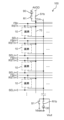
- FIG. 2 is a diagram showing the circuit configuration of the imaging device 100.
- FIG. 3 is a diagram showing the circuit configuration of a pixel 10 in the imaging device 100. Note that FIG. 2 shows the circuit configuration of the imaging device 100, focusing on the control lines and signal lines connected to the pixel 10. For this reason, some circuit elements are not shown in FIG. 2. Also, the circuit configuration within the pixel 10 in FIG. 2 is shown in FIG. 3.
- Each pixel 10 is connected to a power supply line 70.
- An address control line SEL, a reset control line RST, and a feedback control line FB are provided for each row of pixels 10.
- the address control line SEL, the reset control line RST, and the feedback control line FB correspond to the row control line L described above.
- the address control line SEL, the reset control line RST, and the feedback control line FB are each electrically connected to one or more pixels 10 belonging to the same row.
- the characters n, n+1, etc. added after the reference symbols of the address control line SEL, the reset control line RST, and the feedback control line FB represent the row of the pixel 10, where n is an integer of 0 or more, such as 0 or 1.
- the address control line SELn represents that it is the address control line SELn connected to the pixel 10 in the nth row.
- the characters m, etc. added after the reference symbols of the vertical signal lines C represent the column of the pixel 10, where m is an integer of 0 or more, such as 0 or 1.
- vertical signal line Cm indicates that the vertical signal line C is connected to the pixel 10 in the mth column.
- Each pixel 10 has a photoelectric conversion unit 13, an amplifier transistor 24, an address transistor 26, a reset transistor 28, a band control transistor 81, a capacitance element 82, and a capacitance element 83.
- the photoelectric conversion unit 13 receives incident light and generates a signal.
- the photoelectric conversion unit 13 is, for example, stacked on the semiconductor substrate 110.
- the photoelectric conversion unit 13 does not need to be an independent element for each pixel 10 in its entirety, and for example, a portion of the photoelectric conversion unit 13 may span multiple pixels 10.
- the photoelectric conversion unit 13 of each pixel 10 is further connected to a bias control line 42 and a predetermined voltage is applied to it. As described above, the bias control line 42 is connected to the voltage supply circuit 150.
- the amplification transistor 24, address transistor 26, reset transistor 28, and band control transistor 81 are, for example, field effect transistors (FETs).
- FETs field effect transistors
- N-channel MOSFETs Metal Oxide Semiconductor Field Effect Transistors
- the control terminal is, for example, a gate electrode.
- the input terminal is one of the drain and source, for example, the drain.
- the output terminal is the other of the drain and source, for example, the source.
- the control terminal which is the gate electrode of the amplification transistor 24, is connected to the photoelectric conversion unit 13.
- the signal charge generated by the photoelectric conversion unit 13 is accumulated in the charge accumulation unit 71 between the gate electrode of the amplification transistor 24 and the photoelectric conversion unit 13.
- the signal charge is a hole or an electron.
- the charge storage section 71 includes, for example, a node connected to the gate electrode of the amplification transistor 24.
- the charge storage section 71 is also called a "floating diffusion node.” The structure of the photoelectric conversion section 13 will be described in detail later.
- the input terminal of the amplifying transistor 24 is connected to the power supply line 70.
- the power supply line 70 is connected to the switch S1b and the switch R1.
- the switch S1b controls whether or not to connect the power supply line 70 to the analog power supply AVDD.
- the switch R1 controls whether or not to connect the power supply line 70 to the constant current source 90 that flows from the analog power supply AVDD.
- the output terminal of the amplifying transistor 24 is connected to the input terminal of the address transistor 26.
- the output terminal of the address transistor 26 is connected to a vertical signal line C.
- the vertical signal line C is connected to a switch R1b, a switch S1, and a signal processing circuit 130 (see FIG. 1).
- the switch R1b controls whether or not to connect the vertical signal line C to a constant current source 30 connected to an analog ground.
- the switch S1 controls whether or not to connect the vertical signal line C to a voltage Vbias.
- the switch R1b, the switch S1, and the constant current source 30 are provided for each column of multiple pixels 10.
- Switch S1b, switch R1, switch R1b, and switch S1 are, for example, field effect transistors.
- the operation of switch S1b, switch R1, switch R1b, and switch S1 is, for example, controlled by control circuit 140.
- the power supply line 70 functions as a source follower power supply.
- the amplifier transistor 24 amplifies and outputs the potential of the charge storage section 71.
- a signal Vout which is a source follower output according to the potential of the gate of the amplifier transistor 24, is output to the signal processing circuit 130 via the vertical signal line C as a pixel signal or a reference signal.
- the output terminal of the amplifying transistor 24 is connected to the input terminal of the address transistor 26.
- the output terminal of the address transistor 26 is connected to the vertical signal line C.
- the control terminal of the address transistor 26 is connected to the address control line SEL. By controlling the potential of the address control line SEL, the output of the amplifying transistor 24 can be selectively output to the vertical signal line C for multiple pixels 10.
- the address control line SEL is connected to a row scanning circuit 120 (see FIG. 1).
- the row scanning circuit 120 applies a predetermined voltage to the address control line SEL to select a plurality of pixels 10 arranged in each row on a row-by-row basis. This causes the signal of the selected pixel 10 to be output.
- the reset transistor 28 is connected between the band control transistor 81 and the charge storage section 71.
- the control terminal of the reset transistor 28 is connected to a reset control line RST. By controlling the potential of the reset control line RST, the potential of the charge storage section 71 of the pixel 10 can be reset.
- the band control transistor 81 is connected between the power line 70 and the reset transistor 28, and constitutes an in-pixel feedback amplifier during a reset operation.
- the input terminal of the band control transistor 81 is connected to the power line 70.
- the output terminal of the band control transistor 81 is connected to the input terminal of the reset transistor 28, one end of the capacitance element 82, and one end of the capacitance element 83.
- the feedback control line FB is connected to the control terminal of the band control transistor 81 and the row scanning circuit 120 (see FIG. 1).
- the state of the band control transistor 81 is determined by the potential of the feedback control line FB. For example, by controlling the potential of the feedback control line FB, a feedback path is formed by the charge storage unit 71, the amplification transistor 24, and the band control transistor 81.
- the pixel 10 includes a feedback circuit that negatively feeds back reset noise.
- the capacitance elements 82 and 83 function as negative feedback capacitances when resetting the potential of the charge storage section 71 in the in-pixel feedback amplifier, and reduce reset noise when resetting the potential of the charge storage section 71.
- One end of the capacitance element 82 is connected to one end of the capacitance element 83, the input terminal of the reset transistor 28, and the output terminal of the band control transistor 81.
- the other end of the capacitance element 82 is applied with, for example, a reference voltage VR.
- One end of the capacitance element 83 is connected to one end of the capacitance element 82, the input terminal of the reset transistor 28, and the output terminal of the band control transistor 81.
- the other end of the capacitance element 83 is connected to the control terminal of the amplification transistor 24 and the output terminal of the reset transistor 28.
- the capacitance elements 82 and 83 are, for example, MIM (Metal Insulator Metal) capacitances or MIS (Metal Insulator Semiconductor) capacitances.
- the photoelectric conversion unit 13 includes a pixel electrode 11, a counter electrode 12, and a photoelectric conversion layer 15 disposed between the pixel electrode 11 and the counter electrode 12.
- the pixel electrode 11, the photoelectric conversion layer 15, and the counter electrode 12 are stacked in this order on the semiconductor substrate 110, for example.
- the photoelectric conversion unit 13 may further include other elements such as an electron blocking layer and a hole blocking layer.
- the counter electrode 12 and the photoelectric conversion layer 15 are formed, for example, across multiple pixels 10.
- a pixel electrode 11 is provided for each pixel 10.
- the pixel electrode 11 is electrically isolated from the pixel electrodes 11 of the other pixels 10.
- At least one of the counter electrode 12 and the photoelectric conversion layer 15 may be provided separately for one or more pixels 10.
- the pixel electrode 11 is electrically connected to the photoelectric conversion layer 15 and is an electrode for collecting signal charges generated in the photoelectric conversion layer 15.
- the pixel electrode 11 is connected to the charge accumulation section 71.
- the pixel electrode 11 is formed using a conductive material. The signal charges collected by the pixel electrode 11 are accumulated in the charge accumulation section 71.
- the counter electrode 12 is, for example, a transparent electrode made of a transparent conductive material.
- the counter electrode 12 is disposed on the side of the photoelectric conversion layer 15 where light is incident.
- the counter electrode 12 is connected to the voltage supply circuit 150 shown in FIG. 1 via the bias control line 42.
- the voltage supply circuit 150 controls the potential of the counter electrode 12 relative to the potential of the pixel electrode 11, so that either the holes or the electrons of the hole-electron pairs generated in the photoelectric conversion layer 15 by photoelectric conversion can be collected by the pixel electrode 11 as signal charges.
- the pixel electrode 11 can selectively collect the holes by making the counter electrode 12 higher in potential than the pixel electrode 11. It is also possible to selectively collect electrons by the pixel electrode 11 by making the counter electrode 12 lower in potential than the pixel electrode 11.
- the photoelectric conversion layer 15 is a layer that absorbs photons and generates photocharges that become signal charges. Specifically, the photoelectric conversion layer 15 receives incident light and generates hole-electron pairs. That is, the signal charge is either a hole or an electron. For example, when holes are used as the signal charge, the holes are collected by the pixel electrode 11. Electrons, which are charges of the opposite polarity to the signal charge, are collected by the counter electrode 12.
- the photoelectric conversion layer 15 is made of a photoelectric conversion material, and is formed, for example, from an organic semiconductor material. The photoelectric conversion layer 15 may also be formed from an inorganic semiconductor material.
- circuit configuration of pixel 10 is not limited to the example described using Figures 2 and 3, and various circuit configurations of pixels of imaging devices described in Patent Document 1, etc., can be applied.
- FIG. 4 is a timing chart of a first operation example of the imaging device 100.
- FIG. 4 shows changes in the potentials of the address control line SEL and the reset control line RST of the nth row to the n+3th row of a plurality of pixels 10.
- the address transistor 26 is conductive when the potential of the address control line SEL is at a high level, and is non-conductive when the potential of the address control line SEL is at a low level.
- the reset transistor 28 is conductive when the potential of the reset control line RST is at a high level, and is non-conductive when the potential of the reset control line RST is at a low level.
- the operation of the pixel 10 in the mth column and the corresponding peripheral circuit will be explained, but similar operations are performed for the pixels 10 in other columns.
- the mth column of the multiple pixels 10 is an example of a first column.
- the nth row of the multiple pixels 10 is an example of a first row.
- the n+1th row of the multiple pixels 10 is an example of a second row different from the first row.
- the pixel 10 arranged in the nth row and mth column is an example of a first pixel.
- the pixel 10 arranged in the n+1th row and mth column is an example of a second pixel.
- a plurality of pixels 10 are exposed to light, and the signal charge generated by the photoelectric conversion unit 13 is accumulated in the charge accumulation unit 71 of each pixel 10.
- the exposure of the plurality of pixels 10 is performed, for example, by a global shutter method.
- the voltage supply circuit 150 supplies a first voltage to the counter electrode 12 such that the potential of the counter electrode 12 is sufficiently higher than that of the pixel electrode 11.
- holes, which are signal charges generated by photoelectric conversion of the photoelectric conversion layer 15 move to the pixel electrode 11 and are accumulated in the charge accumulation unit 71.
- the voltage supply circuit 150 supplies a second voltage to the counter electrode 12 such that the movement of signal charges does not substantially occur in the photoelectric conversion unit 13.
- the voltage supply circuit 150 supplies the counter electrode 12 with a second voltage that makes the potential difference between the pixel electrode 11 and the counter electrode 12 smaller than when the first voltage is supplied, for example, such that the potential difference is close to zero (for example, 1 V or less).
- the exposure of the multiple pixels 10 may be performed by a rolling shutter method.
- the same first voltage as during exposure is supplied to the counter electrode 12 even after exposure, and the exposure period is from when the pixel 10 is reset to when the first pixel signal is output.
- the pixel 10 may be reset again after being reset immediately before outputting the reference signal.
- the potential of the address control line SELn becomes high level, and the address transistor 26 of the pixel 10 in the nth row becomes conductive. In other words, the pixel 10 in the nth row becomes selected.
- the switch S1 is turned off, the switch S1b is turned on, the switch R1 is turned off, and the switch R1b is turned on.
- a pixel signal corresponding to the amount of signal charge accumulated in the charge accumulation section 71 of the pixel 10 in the nth row is output to the vertical signal line Cm.
- the potential of the address control line SELn+1 also becomes high level, and the address transistor 26 of the pixel 10 in the n+1th row also becomes conductive.
- the pixel 10 in the n+1th row becomes selected.
- a pixel signal corresponding to the amount of signal charge accumulated in the charge accumulation section 71 of the pixel 10 in the n+1th row is output to the vertical signal line Cm.
- the pixel signal output by the pixel 10 in the nth row and the pixel signal output by the pixel 10 in the n+1th row are mixed on the vertical signal line Cm.
- the signal processing circuit 130 reads out the pixel signal output to the vertical signal line Cm.
- the signal processing circuit 130 temporarily holds a voltage level corresponding to the pixel signal output to the vertical signal line Cm.
- the signal processing circuit 130 may include a capacitive element for holding this voltage level.
- the pixel signal read out to the signal processing circuit 130 is designated as Sn_n+1.
- the potential of the reset control line RSTn becomes high level, and the reset transistor 28 of the pixel 10 in the nth row becomes conductive.
- the potential of the feedback control line FBn also becomes high level, and the band control transistor 81 also becomes conductive.
- the switch S1 turns on, the switch S1b turns off, the switch R1 turns on, and the switch R1b turns off.
- the amplification transistor 24, the vertical signal line Cm, the power supply line 70, and the constant current source 90 beyond it form a source-grounded amplifier. This resets the pixel 10 in the nth row.
- the potential of the charge storage unit 71 of the pixel 10 in the nth row is reset to Vbias.
- the potential of the address control line SELn+1 goes to low level, and the address transistor 26 of the pixel 10 in the n+1th row goes into a non-conducting state. In other words, the pixel 10 in the n+1th row goes into a non-selected state. Furthermore, the potential of the reset control line RSTn+1 remains at low level. Therefore, the pixel 10 in the n+1th row is not reset.
- the potential of the reset control line RSTn becomes low level, and the reset transistor 28 of the pixel 10 in the nth row becomes non-conductive.
- the potential of the feedback control line FBn becomes an intermediate potential between high level and low level, and the band control transistor 81 functions as a resistance circuit to form a negative feedback amplifier.
- the switch S1 is turned off, the switch S1b is turned on, the switch R1 is turned off, and the switch R1b is turned on.
- a reference signal which is a signal after the reset of the pixel 10 in the nth row, that is, a reference signal corresponding to the potential of the reset charge storage unit 71, is output to the vertical signal line Cm.
- the pixel 10 in the nth row is reset after outputting the pixel signal, and outputs the reference signal after the reset.
- the signal of the pixel 10 in the n+1th row is not output to the vertical signal line Cm. In other words, only the reference signal of the pixel 10 in the nth row is output to the vertical signal line Cm.
- the reset of pixel 10 may be completed by the potential of feedback control line FBn becoming low level without taking an intermediate potential between high level and low level. Also, if pixel 10 does not have a configuration that includes a feedback circuit, the reset is completed at time t4.
- the signal processing circuit 130 reads out the reference signal output to the vertical signal line Cm.
- the reference signal read out to the signal processing circuit 130 is designated as Rn.
- the signal processing circuit 130 then generates an image signal for the pixel 10 in the nth row.
- the image signal for the pixel 10 in the nth row is obtained as a differential signal (Sn_n+1-Rn) between the pixel signal Sn_n+1 and the reference signal Rn.
- the signal processing circuit 130 obtains the differential signal, for example, from the output voltage difference between the voltage corresponding to the pixel signal Sn_n+1 and the voltage corresponding to the reference signal Rn.
- the potential of the address control line SELn becomes low level, and the address transistor 26 of the pixel 10 in the nth row becomes non-conductive. In other words, the pixel 10 in the nth row becomes unselected.
- the potential of the address control line SELn+1 becomes high level, and the address transistor 26 of the pixel 10 in the n+1th row becomes conductive. That is, the pixel 10 in the n+1th row becomes selected.
- the switch S1 turns off, the switch S1b turns on, the switch R1 turns off, and the switch R1b turns on.
- a pixel signal corresponding to the amount of signal charge accumulated in the charge accumulation section 71 of the pixel 10 in the n+1th row is output to the vertical signal line Cm.
- the pixel signal of the pixel 10 in the n+1th row is output from time t1 to time t3, but it is output in a non-destructive manner, and the pixel 10 in the n+1th row is not reset. Therefore, the pixel 10 in the n+1th row can output a pixel signal again. Also, since the voltage supply circuit 150 applies to the opposing electrode 12 a second voltage that does not substantially accumulate signal charge in the charge accumulation section 71, the output value of the pixel signal of the pixel 10 in the n+1th row does not change even if time passes.
- the potential of the address control line SELn+2 also goes high, and the address transistor 26 of the pixel 10 in the n+2th row also goes conductive.
- the pixel 10 in the n+2th row goes into a selected state.
- a pixel signal corresponding to the amount of signal charge accumulated in the charge accumulation section 71 of the pixel 10 in the n+2th row is output to the vertical signal line Cm.
- the pixel signal output by the pixel 10 in the n+1th row and the pixel signal output by the pixel 10 in the n+2th row are mixed on the vertical signal line Cm.
- the signal processing circuit 130 reads out the pixel signal output to the vertical signal line Cm.
- the pixel signal read out by the signal processing circuit 130 is designated as Sn+1_n+2.
- the potential of the reset control line RSTn+1 goes high, and the reset transistor 28 of the pixel 10 in the n+1th row goes into a conductive state.
- the potential of the feedback control line FBn+1 also goes high, and the band control transistor 81 also goes into a conductive state.
- the switch S1 turns on, the switch S1b turns off, the switch R1 turns on, and the switch R1b turns off. This resets the pixel 10 in the n+1th row.
- the potential of the charge storage unit 71 of the pixel 10 in the n+1th row is reset to Vbias.
- the potential of the address control line SELn+2 goes to low level, and the address transistor 26 of the pixel 10 in the n+2th row goes into a non-conducting state. In other words, the pixel 10 in the n+2th row goes into a non-selected state. Furthermore, the potential of the reset control line RSTn+2 remains at low level. Therefore, the pixel 10 in the n+2th row is not reset.
- the potential of the reset control line RSTn+1 becomes low level, and the reset transistor 28 of the pixel 10 in the n+1th row becomes non-conductive.
- the potential of the feedback control line FBn+1 becomes an intermediate potential between high level and low level, and the band control transistor 81 functions as a resistance circuit to form a negative feedback amplifier.
- the band control transistor 81 becomes non-conductive, and the reset of the potential of the charge storage unit 71 is completed.
- the switch S1 is turned off, the switch S1b is turned on, the switch R1 is turned off, and the switch R1b is turned on.
- the reference signal which is the signal after the reset of the pixel 10 in the n+1th row, is output to the vertical signal line Cm.
- the signal of the pixel 10 in the n+2th row is not output to the vertical signal line Cm. In other words, only the reference signal of the pixel 10 in the n+1th row is output to the vertical signal line Cm.
- the signal processing circuit 130 reads out the reference signal output to the vertical signal line Cm.
- the reference signal read out to the signal processing circuit 130 is set to Rn+1.
- the signal processing circuit 130 generates an image signal for the pixel 10 in the n+1th row.
- the image signal for the pixel 10 in the n+1th row is obtained as a differential signal (Sn+1_n+2-Rn+1) between the pixel signal Sn+1_n+2 and the reference signal Rn+1.
- the potential of the address control line SELn+1 goes to low level, and the address transistor 26 of the pixel 10 in the n+1th row goes into a non-conducting state. In other words, the pixel 10 in the n+1th row goes into a non-selected state.
- the potential of the address control line SELn+2 goes high, and the address transistor 26 of the pixel 10 in the n+2th row becomes conductive. In other words, the pixel 10 in the n+2th row becomes selected. Thereafter, in all rows of the pixels 10 from the n+2th row onwards, the same operation as the nth and n+1th rows described above is performed for each row of the pixels 10. As a result, image signals for pixels in the same number of rows as the number of rows of the pixels 10 are output from the signal processing circuit 130.
- the pixels 10 sequentially output pixel signals and reference signals to the vertical signal line Cm for each readout row consisting of one row of the pixels 10. Also, during the first period (from time t1 to time t3) in which the pixels 10 in the nth row, which is the readout row, output pixel signals, the pixels 10 in the n+1th row, which is the readout row after the nth row, also output pixel signals. Also, during the second period (from a predetermined time between times t4 and t5 to time t6) in which the pixels 10 in the nth row output reference signals, the pixels 10 in the n+1th row do not output reference signals.
- the pixels 10 in the n+1th row output pixel signals again before resetting.
- the signal processing circuit 130 generates image data based on the pixel signals Sn_n+1 output by the pixels 10 in the nth row and the pixels 10 in the n+1th row to the vertical signal line Cm during the first period, and the reference signal Rn output by the pixels 10 in the nth row to the vertical signal line Cm.
- the pixel signals of the pixels 10 of two rows are simultaneously output to the vertical signal line Cm and mixed.
- the effective gate width of the amplifying transistor 24 is doubled, and the mutual conductance gm of the amplifying transistor 24 is ⁇ 2 times.
- the random noise caused by the amplifying transistor 24 is proportional to 1/gm. Therefore, it is possible to realize low noise by simultaneously outputting the pixel signals of the pixels 10 of two rows to the vertical signal line Cm.
- the settling time is also proportional to 1/gm. Therefore, it is possible to realize high-speed driving by simultaneously outputting the pixel signals of the pixels 10 of two rows to the vertical signal line Cm. For example, it is possible to set the time from time t1 to time t2 to be shorter.
- the term "readout row” refers to a row with a different concept from the row from which the pixels 10 output signals, and is a row of multiple pixels 10 from which signals are read out as an image signal by the signal processing circuit 130.
- the readout row is a row of multiple pixels 10 that corresponds one-to-one to the row of pixels in the image signal (image data) output by the signal processing circuit 130.
- the above effect can be obtained by outputting pixel signals from pixels 10 in a row other than the readout row at the same time as the pixels 10 in the readout row.
- the "next readout row" when obtaining a color image is the next readout row of pixels 10 of the same color.
- Operation example 2 Next, a description will be given of an operation example 2 of the imaging device 100. In the following description of the operation example 2, differences from the operation example 1 will be mainly described, and descriptions of commonalities will be omitted or simplified.
- the operation example 2 is an example of an operation in which the signal processing circuit 130 generates an image signal using a reference signal stored in the memory 170.
- FIG. 5 is a timing chart of operation example 2 of the imaging device 100. The same items as in FIG. 4 are shown in FIG. 5.
- operation example 2 the operation of the pixel 10 in the mth column and the corresponding peripheral circuitry will be described, but similar operations are also performed for the pixels 10 in the other columns.
- the potential of the address control line SELn goes high, and the address transistor 26 of the pixel 10 in the nth row goes into a conductive state.
- the potential of the reset control line RSTn goes high, and the reset transistor 28 of the pixel 10 in the nth row goes into a conductive state.
- the potential of the feedback control line FBn also goes high, and the band control transistor 81 also goes into a conductive state.
- the switch S1 is turned on, the switch S1b is turned off, the switch R1 is turned on, and the switch R1b is turned off. This resets the pixel 10 in the nth row.
- the potential of the reset control line RSTn becomes low level, and the reset transistor 28 of the pixel 10 in the nth row becomes non-conductive.
- the potential of the feedback control line FBn becomes an intermediate potential between high level and low level.
- the band control transistor 81 becomes non-conductive, and the reset of the potential of the charge storage unit 71 is completed.
- the switch S1 is turned off, the switch S1b is turned on, the switch R1 is turned off, and the switch R1b is turned on.
- the reference signal after the reset of the pixel 10 in the nth row is output to the vertical signal line Cm.
- the signal of the pixel 10 in the n+1th row is not output to the vertical signal line Cm. In other words, only the reference signal of the pixel 10 in the nth row is output to the vertical signal line Cm.
- the signal processing circuit 130 reads out the reference signal output to the vertical signal line Cm.
- the reference signal read out by the signal processing circuit 130 is designated as Rn.
- the signal processing circuit 130 stores the read out reference signal Rn in the memory 170.
- the signal processing circuit 130 stores, for example, the digital value of the reference signal Rn after AD conversion in the memory 170.
- the potential of the address control line SELn becomes low level, and the address transistor 26 of the pixel 10 in the nth row becomes non-conductive.
- the potential of the address control line SELn+1 goes high, and the address transistor 26 of the pixel 10 in the n+1th row goes into a conductive state.
- the potential of the reset control line RSTn+1 goes high, and the reset transistor 28 of the pixel 10 in the n+1th row goes into a conductive state.
- the potential of the feedback control line FBn+1 also goes high, and the band control transistor 81 goes into a conductive state.
- the switch S1 goes on, the switch S1b goes off, the switch R1 goes on, and the switch R1b goes off. This resets the pixel 10 in the n+1th row.
- the potential of the reset control line RSTn+1 becomes low level, and the reset transistor 28 of the pixel 10 in the n+1th row becomes non-conductive.
- the potential of the feedback control line FBn+1 becomes an intermediate potential between high level and low level.
- the band control transistor 81 becomes non-conductive, and the reset of the potential of the charge storage unit 71 is completed.
- the switch S1 is turned off, the switch S1b is turned on, the switch R1 is turned off, and the switch R1b is turned on.
- the reference signal after reset of the pixel 10 in the n+1th row is output to the vertical signal line Cm.
- the signal of the pixel 10 in the n+2th row is not output to the vertical signal line Cm. In other words, only the reference signal of the pixel 10 in the n+1th row is output to the vertical signal line Cm.
- the signal processing circuit 130 reads out the reference signal output to the vertical signal line Cm.
- the reference signal read out by the signal processing circuit 130 is assumed to be Rn+1.
- the signal processing circuit 130 stores the read out reference signal Rn+1 in the memory 170.
- the signal processing circuit 130 stores, for example, the digital value of the reference signal Rn+1 after AD conversion in the memory 170.
- the potential of the address control line SELn becomes high level, and the address transistor 26 of the pixel 10 in the nth row becomes conductive.
- the switch S1 is turned off, the switch S1b is turned on, the switch R1 is turned off, and the switch R1b is turned on.
- a pixel signal corresponding to the amount of signal charge accumulated in the charge accumulation section 71 of the pixel 10 in the nth row is output to the vertical signal line Cm.
- the potential of the address control line SELn+1 goes high, and the address transistor 26 of the pixel 10 in the n+1th row becomes conductive.
- This causes a pixel signal corresponding to the amount of signal charge accumulated in the charge accumulation section 71 of the pixel 10 in the n+1th row to be output to the vertical signal line Cm.
- the pixel signal output by the pixel 10 in the nth row and the pixel signal output by the pixel 10 in the n+1th row are mixed on the vertical signal line Cm.
- the signal processing circuit 130 reads out the pixel signal output to the vertical signal line Cm.
- the pixel signal read out to the signal processing circuit 130 is designated as Sn_n+1.
- the signal processing circuit 130 then generates an image signal for the pixel 10 in the nth row.
- the image signal for the pixel 10 in the nth row is obtained as a difference signal between the pixel signal Sn_n+1 and the average value of the reference signal Rn and the reference signal Rn+1.
- the signal processing circuit 130 After AD conversion of the read pixel signal Sn_n+1, the signal processing circuit 130 refers to the reference signal Rn and the reference signal Rn+1 stored in the memory 170, and performs a calculation process to subtract the average value of the reference signal Rn and the reference signal Rn+1 from the pixel signal Sn_n+1, thereby acquiring the image signal for the pixel 10 in the nth row.
- the potential of the address control line SELn becomes low level, and the address transistor 26 of the pixel 10 in the nth row becomes non-conductive.
- the potential of the address control line SELn+1 remains high level, and the address transistor 26 of the pixel 10 in the n+1th row continues to be in a conductive state. Therefore, even at time t11, the pixel signal of the pixel 10 in the n+1th row is still output to the vertical signal line Cm.
- the potential of the address control line SELn+2 goes high, and the address transistor 26 of the pixel 10 in the n+2th row becomes conductive.
- This causes a pixel signal corresponding to the amount of signal charge accumulated in the charge accumulation section 71 of the pixel 10 in the n+2th row to be output to the vertical signal line Cm.
- the pixel signal output by the pixel 10 in the n+1th row and the pixel signal output by the pixel 10 in the n+2th row are mixed on the vertical signal line Cm.
- the signal processing circuit 130 reads out the pixel signal output to the vertical signal line Cm.
- the pixel signal read out to the signal processing circuit 130 is set as Sn+1_n+2.
- the signal processing circuit 130 generates an image signal for the pixel 10 in the n+1th row.
- the image signal for the pixel 10 in the n+1th row is obtained as a difference signal between the pixel signal Sn+1_n+2 and the average value of the reference signal Rn+1 and the reference signal Rn+2.
- the signal processing circuit 130 refers to the reference signal Rn+1 stored in the memory 170 and the reference signal Rn+2 of the pixel 10 in the n+2th row, and performs a calculation process to subtract the average value of the reference signal Rn+1 and the reference signal Rn+2 from the pixel signal Sn+1_n+2, thereby acquiring the image signal for the pixel 10 in the n+1th row.
- the signal processing circuit 130 generates image data based on the reference signal Rn output by the pixel 10 in the nth row to the vertical signal line Cm, the reference signal Rn+1 output by the pixel 10 in the n+1th row to the vertical signal line Cm, and the pixel signal Sn_n+1 output by the pixel 10 in the nth row and the pixel 10 in the n+1th row to the vertical signal line Cm during the first period.
- pixel signals of two rows of pixels 10 are simultaneously output to the vertical signal line Cm, thereby realizing low noise and high-speed driving. Furthermore, the signal processing circuit 130 generates image data using the reference signals of the two rows of pixels 10 and a pixel signal obtained by mixing the pixel signals of the two rows of pixels 10. Therefore, the reset noise of the two rows of pixels 10 is superimposed on both the reference signal and the pixel signal used to generate the image data. Therefore, by subtracting the reference signals of the two rows of pixels 10 from the pixel signal obtained by mixing the pixel signals of the two rows of pixels 10, the effect of the reset noise can be removed, and further noise reduction can be achieved.
- reset noise from the reset before the pixel signal is output is superimposed on the pixel signal
- reset noise from the reset after the pixel signal is output is superimposed on the reference signal.
- reset noise due to different reset operations is superimposed on the reference signal and the pixel signal.
- operation example 2 after the pixel 10 in the nth row outputs the reference signal after reset, it accumulates signal charge during the exposure period and then outputs the pixel signal. As a result, reset noise due to the same reset operation is superimposed on the reference signal and the pixel signal. Therefore, by subtracting the reference signal from the pixel signal, the effects of the reset noise can be accurately removed, and further noise reduction can be achieved.
- the imaging device 100 performs the operation of Operation Example 2, the effect of the reset noise can be reduced, so the imaging device 100 does not need to include a feedback circuit that negatively feeds back the reset noise. This makes it possible to simplify the pixel circuit.
- the signal processing circuit 130 generates image data using the reference signals of two rows of pixels 10 stored in the memory 170, but image data may also be generated using the reference signals of one row of pixels 10 (i.e., the pixels 10 in the readout row).
- the signal processing circuit 130 may output the pixel signal and the reference signal after AD conversion to the outside without generating image data, and the external processing circuit may store the output reference signal in an external memory and generate the above image data.
- the operation example 3 is an example of an operation in which pixel signals of pixels 10 in three rows are simultaneously output to the vertical signal line C.
- FIG. 6 is a timing chart of operation example 3 of the imaging device 100. The same items as in FIG. 4 are shown in FIG. 6.
- operation example 3 the operation of the pixel 10 in the mth column and the corresponding peripheral circuitry will be described, but similar operations are performed for the pixels 10 in the other columns.
- the n+2th row of the multiple pixels 10 is an example of a third row that is different from the first row and the second row.
- the potential of the address control line SELn becomes high level, and the address transistor 26 of the pixel 10 in the nth row becomes conductive.
- the switch S1 is turned off, the switch S1b is turned on, the switch R1 is turned off, and the switch R1b is turned on.
- a pixel signal corresponding to the amount of signal charge accumulated in the charge accumulation section 71 of the pixel 10 in the nth row is output to the vertical signal line Cm.
- the potentials of the address control lines SELn+1 and SELn+2 also go to a high level, and the address transistors 26 of the pixels 10 in the n+1th and n+2th rows also go into a conductive state.
- pixel signals corresponding to the amounts of signal charge accumulated in the charge accumulation units 71 of the pixels 10 in the n+1th and n+2th rows are output to the vertical signal line Cm.
- the pixel signals output by the pixels 10 in the nth row, the pixel signals output by the pixels 10 in the n+1th row, and the pixel signals output by the pixels 10 in the n+2th row are mixed on the vertical signal line Cm.
- the signal processing circuit 130 reads out the pixel signal output to the vertical signal line Cm.
- the pixel signal read out by the signal processing circuit 130 is designated as Sn_n+1_n+2.
- the potential of the reset control line RSTn goes high, and the reset transistor 28 of the pixel 10 in the nth row goes conductive.
- the potential of the feedback control line FBn also goes high, and the band control transistor 81 goes conductive.
- the switch S1 turns on, the switch S1b turns off, the switch R1 turns on, and the switch R1b turns off. This resets the pixel 10 in the nth row, and the potential of the charge storage unit 71 of the pixel 10 in the nth row is reset to Vbias.
- the potentials of the address control lines SELn+1 and SELn+2 become low level, and the address transistors 26 of the pixels 10 in the n+1th and n+2th rows become non-conductive.
- the pixels 10 in the nth row are reset in the same manner as in operation example 1.
- the reference signal after the pixels 10 in the nth row are reset is output to the vertical signal line Cm.
- the signal processing circuit 130 reads out the reference signal output to the vertical signal line Cm.
- the reference signal read out to the signal processing circuit 130 is designated as Rn.
- the signal processing circuit 130 generates an image signal for the pixel 10 in the nth row.
- the image signal for the pixel 10 in the nth row is obtained as a difference signal (Sn_n+1_n+2-Rn) between the pixel signal Sn_n+1_n+2 and the reference signal Rn.
- the potential of the address control line SELn goes low, and the address transistor 26 of the pixel 10 in the nth row goes non-conductive.
- the potential of the address control line SELn+1 goes high, and the address transistor 26 of the pixel 10 in the n+1th row goes conductive.
- the potentials of the address control lines SELn+2 and SELn+3 also go high, and the address transistors 26 of the pixels 10 in the n+2th and n+3th rows also go conductive.
- the same operation as that in the nth row described above is performed for each row of the pixels 10.
- pixel signals from three rows of pixels 10 are simultaneously output to the vertical signal line Cm and mixed. If the pixel signals from three rows of pixels 10 have approximately the same values, the effective gate width of the amplifying transistor 24 becomes three times larger, and the mutual conductance gm of the amplifying transistor 24 becomes ⁇ 3 times larger. Therefore, by simultaneously outputting pixel signals from three rows of pixels 10 to the vertical signal line Cm, it becomes possible to achieve even lower noise and faster driving.
- the pixels 10 in each row may output a reference signal, accumulate signal charge during the exposure period, and then output a pixel signal.
- Operation example 4 is an example of an operation in which pixel signals and reference signals of the pixels 10 are read out for each readout row consisting of two rows.
- FIG. 7 is a timing chart of operation example 4 of the imaging device 100. The same items as in FIG. 4 are shown in FIG. 7. In the following explanation of operation example 4, the operation of the pixel 10 in the mth column and the corresponding peripheral circuitry will be described, but similar operations are also performed for the pixels 10 in the other columns.
- the potentials of the address control lines SELn and SELn+1 go to high level, and the address transistors 26 of the pixels 10 in the nth and n+1th rows become conductive.
- the switch S1 turns off, the switch S1b turns on, the switch R1 turns off, and the switch R1b turns on.
- pixel signals corresponding to the amount of signal charge accumulated in the charge accumulation units 71 of the pixels 10 in the nth and n+1th rows are output to the vertical signal line Cm.
- the potentials of the address control lines SELn+2 and SELn+3 also go high, and the address transistors 26 of the pixels 10 in the n+2th and n+3th rows also go conductive.
- pixel signals corresponding to the amount of signal charge accumulated in the charge accumulation units 71 of the pixels 10 in the n+2th and n+3th rows are output to the vertical signal line Cm.
- the pixel signals output by the pixels 10 in the nth row, the pixel signals output by the pixels 10 in the n+1th row, the pixel signals output by the pixels 10 in the n+2th row, and the pixel signals output by the pixels 10 in the n+3th row are mixed on the vertical signal line Cm.
- the signal processing circuit 130 reads out the pixel signal output to the vertical signal line Cm.
- the pixel signal read out by the signal processing circuit 130 is designated as Sn_n+1_n+2_n+3.
- the potentials of the reset control lines RSTn, RSTn+1 go to high level, and the reset transistors 28 of the pixels 10 in the nth and n+1th rows go into a conductive state.
- the potentials of the feedback control lines FBn, FBn+1 also go to high level, and the band control transistors 81 go into a conductive state.
- the switch S1 goes on, the switch S1b goes off, the switch R1 goes on, and the switch R1b goes off. This resets the pixels 10 in the nth and n+1th rows. Specifically, the potentials of the charge storage units 71 of the pixels 10 in the nth and n+1th rows are reset to Vbias.
- the potentials of the address control lines SELn+2 and SELn+3 become low level, and the address transistors 26 of the pixels 10 in the n+2th and n+3th rows become non-conductive.
- the pixels 10 in the nth row and the n+1th row are reset in the same manner as in operation example 1.
- the reference signals after the pixels 10 in the nth row and the n+1th row are reset are output to the vertical signal line Cm.
- the signal processing circuit 130 reads out the reference signal output to the vertical signal line Cm.
- the reference signal read out to the signal processing circuit 130 is set to Rn_n+1.
- the signal processing circuit 130 then generates image signals for the pixels 10 in the nth and n+1th rows, which are two readout rows.
- the image signals for the pixels 10 in the nth and n+1th rows are obtained as a difference signal (Sn_n+1_n+2_n+3-Rn_n+1) between the pixel signal Sn_n+1_n+2_n+3 and the reference signal Rn_n+1.
- the potentials of the address control lines SELn and SELn+1 go to low level, and the address transistors 26 of the pixels 10 in the nth and n+1th rows go into a non-conductive state. Also, at time t6, the potentials of the address control lines SELn+2 and SELn+3 go to high level, and the address transistors 26 of the pixels 10 in the n+2th and n+3th rows go into a conductive state. Thereafter, in all rows of the pixels 10 from the n+2th row onwards, the same operation as the nth and n+1th rows is performed for every two rows of the pixels 10. As a result, image signals for pixels in half the number of rows of the pixels 10 are output from the signal processing circuit 130.
- the pixels 10 in each row may output a reference signal, accumulate signal charge during the exposure period, and then output a pixel signal.
- FIG. 8 is a diagram showing the circuit configuration of an imaging device 101 according to this embodiment. Note that FIG. 8 shows the circuit configuration of the imaging device 101, focusing on the control lines and signal lines connected to the pixels 10.
- the imaging device 101 differs from the imaging device 100 according to the first embodiment in that it further includes a switch 29 connected to two adjacent vertical signal lines C.
- the switch 29 is provided between the vertical signal line Cm provided corresponding to the pixel 10 in the mth column and the vertical signal line Cm+1 provided corresponding to the pixel 10 in the m+1th column adjacent to the mth column.
- the vertical signal line Cm is connected to one of two adjacent pixels 10 in the row direction among the multiple pixels 10, and the vertical signal line Cm+1 is connected to the other of the two pixels 10.
- One end of the switch 29 is connected to the vertical signal line Cm, and the other end of the switch 29 is connected to the vertical signal line Cm+1.
- the switch 29 controls whether or not to connect the vertical signal line Cm and the vertical signal line Cm+1.
- one switch 29 is provided for every two adjacent vertical signal lines C, and all vertical signal lines C are connected to one of the vertical signal lines C adjacent to each other in the row direction via the switch 29.
- the switch 29 is, for example, a field effect transistor. If the imaging device 101 further includes a pixel corresponding to a color different from the pixel 10, the vertical signal line Cm may be connected to one of two adjacent pixels 10 in the row direction among the multiple pixels 10 that are pixels of the same color, and the vertical signal line Cm+1 may be connected to the other of the two pixels 10.
- the control terminal of the switch 29 is connected to a switch control line COL.
- the conductive state of the switch 29 is controlled by controlling the potential of the switch control line COL.
- the switch control line COL is connected to, for example, a control circuit 140, and the operation of the switch 29 is controlled by the control circuit 140.
- the imaging device 101 may be configured to be able to control whether three or more vertical signal lines C are conductive or not by a plurality of switches 29, etc.
- FIG. 9 is a timing chart of an example of the operation of the imaging device 101.
- FIG. 9 also shows the change in the potential of the switch control line COL.
- the switch 29 is in a conductive state when the potential of the switch control line COL is at a high level, and is in a non-conductive state when the potential of the switch control line COL is at a low level.
- the operation of the pixels 10 in the mth and m+1th columns and the corresponding peripheral circuits will be described, but similar operations are performed for the pixels 10 in other columns.
- the m+1th column of the multiple pixels 10 is an example of a second column that is different from the first column.
- the potential of the switch control line COL becomes high level, and the switch 29 becomes conductive. That is, the vertical signal line Cm and the vertical signal line Cm+1 become conductive.
- the pixel signal of the pixel 10 in the nth row and mth column and the pixel signal of the pixel 10 in the n+1th row and mth column are output to the vertical signal line Cm, and the pixel signal of the pixel 10 in the nth row and m+1th column and the pixel signal of the pixel 10 in the n+1th row and m+1th column are output to the vertical signal line Cm+1. Since the switch 29 is conductive, these pixel signals are all mixed together.
- the signal processing circuit 130 reads out the pixel signals output to the vertical signal lines Cm and Cm+1.
- the pixel signals read out from either the vertical signal lines Cm or Cm+1 are the same. Therefore, the signal processing circuit 130 may use only one of the pixel signals read out from the vertical signal lines Cm and Cm+1 to generate image data, or may use both pixel signals to generate image data. Furthermore, when the signal processing circuit 130 uses only one pixel signal to generate image data, it does not need to read out the other pixel signal.
- the potential of the switch control line COL becomes low level, and the switch 29 becomes non-conductive. From time t3 to time t6, the switch 29 remains in the non-conductive state, and the same operation as from time t3 to time t6 in operation example 1 of the imaging device 100 is performed. Note that from time t3 to time t4 or from time t3 to time t6, the potential of the switch control line COL may remain at high level. In this case, the pixel 10 is reset, or the pixel 10 is reset and the reference signal of the pixel 10 is output, while the vertical signal line Cm and the vertical signal line Cm+1 remain conductive.
- the same operation as the nth row described above is performed for each row of the pixels 10 in all rows from the n+1th row onwards. Therefore, during the period when the pixel signals of the pixels 10 in each row are being output, the potential of the switch control line COL becomes high level, and the vertical signal line Cm and vertical signal line Cm+1 of the pixels 10 are conductive.
- the switch 29 is conductive during the first period (time t1 to time t3).
- the pixel signals of the pixels 10 in two rows and two columns are simultaneously output to the vertical signal line Cm or the vertical signal line Cm+1, and the pixel signals of the pixels 10 in two rows and two columns are mixed.
- the mutual conductance gm of the amplifying transistor 24 is increased and the signals are averaged in the column direction. Therefore, although the horizontal resolution is half that of the image pickup device 100 in operation example 1, the pixel signals of the pixels 10 in two rows and two columns are simultaneously output to the vertical signal lines Cm and Cm+1, making it possible to achieve even lower noise and faster driving.
- the pixel signals of the pixels 10 in the nth row and the n+1th row are output to the vertical signal lines Cm and Cm+1 during the first period (time t1 to time t3), but this is not limited to this.
- the address control line SELn+1 may not be at a high level, and pixel signals of only the pixels 10 in the nth row may be output to the vertical signal lines Cm and Cm+1.
- pixel signals of pixels 10 in one row and two columns may be output simultaneously to the vertical signal lines Cm and Cm+1 and mixed. This also doubles the effective gate width of the amplification transistor 24, making it possible to achieve low noise and high-speed driving.
- the imaging device 101 may perform other operations similar to any of the operations in operation examples 2 to 4 of the imaging device 100, as long as the imaging device 101 performs an operation in which the potential of the switch control line COL becomes high during the period in which the pixels 10 in each row output pixel signals.
- the imaging device is a stacked type imaging device having a photoelectric conversion section in which a pixel electrode, a photoelectric conversion layer, and an opposing electrode are stacked on a semiconductor substrate, but this is not limited to this.
- the type of photoelectric conversion section of the imaging device is not particularly limited, and the photoelectric conversion section may be, for example, a PD (Photo Diode) or a SPAD (Single Photon Avalanche Diode) that is embedded in a semiconductor substrate.
- the signal processing circuit of the imaging device generates image data, but this is not limited to this.
- the image data may be generated by a separate device.
- the memory in which the reference signal is stored may be provided in a separate device.
- each pixel includes a feedback circuit that negatively feeds back a signal to the charge storage section within the pixel, but this is not limited to the above.
- the imaging device may have a feedback circuit outside the pixel.
- the imaging device may not need to include a feedback circuit.
- the imaging device does not need to include all of the components described in the above embodiments, and may be composed of only the components required to perform the desired operation.
- processing performed by a specific processing unit may be executed by another processing unit.
- the order of multiple processes may be changed, and multiple processes may be executed in parallel.
- each component may be realized by executing a software program suitable for each component.
- Each component may be realized by a program execution unit such as a CPU or processor reading and executing a software program recorded on a recording medium such as a hard disk or semiconductor memory.
- each component may be realized by hardware.
- Each component may be a circuit (or an integrated circuit). These circuits may form a single circuit as a whole, or each may be a separate circuit. Furthermore, each of these circuits may be a general-purpose circuit, or a dedicated circuit.
- the general or specific aspects of the present disclosure may be realized as a system, an apparatus, a method, an integrated circuit, a computer program, or a computer-readable recording medium such as a CD-ROM.
- the present disclosure may be realized as any combination of a system, an apparatus, a method, an integrated circuit, a computer program, and a recording medium.
- the present disclosure may be realized as the imaging device of the above embodiment, as a control device that controls the imaging device, as a program for causing a computer to execute a method for driving the imaging device performed by a processing unit such as a control circuit, or as a non-transitory computer-readable recording medium on which such a program is recorded.
- the imaging device and imaging method disclosed herein can be used in a variety of camera systems and sensor systems, including digital still cameras, broadcast cameras, commercial cameras, medical cameras, surveillance cameras, in-vehicle cameras, digital single-lens reflex cameras, and digital mirrorless cameras.
Landscapes
- Engineering & Computer Science (AREA)
- Multimedia (AREA)
- Signal Processing (AREA)
- Transforming Light Signals Into Electric Signals (AREA)
- Solid State Image Pick-Up Elements (AREA)
Abstract
撮像装置100は、行列状に配列する複数の画素10と、複数の画素10の列毎に設けられた垂直信号線Cと、制御回路140とを備える。複数の画素10のそれぞれは、光を信号電荷に変換する光電変換部を含む。制御回路140は、複数の画素10に対し、画素10に蓄積された信号電荷の量に対応する画素信号と、画素10のリセット後の基準信号とを、垂直信号線Cに出力させる。制御回路140は、第1の行に配置された第1画素に画素信号を出力させる第1期間に、第1画素が配置された第1の列に配置され、かつ、第1の行と異なる第2の行に配置される第2画素にも画素信号を出力させる。制御回路140は、第2画素に対して、第1期間の後、リセットを行う前に、画素信号を再度出力させる。
Description
本開示は、撮像装置に関する。
CCD(Charge Coupled Device)イメージセンサおよびCMOS(ComplementaryMetal Oxide Semiconductor)イメージセンサは、デジタルカメラなどに広く用いられている。
特許文献1は、撮像領域における画素ごとに帰還経路を形成し、負帰還によってリセットノイズをキャンセルする撮像装置を開示している。
特許文献2は、高速な画素混合機能を有する撮像装置を開示している。
低ノイズ化が可能な撮像装置が求められている。
本開示の一態様に係る撮像装置は、行列状に配列する複数の画素と、前記複数の画素の列毎に設けられた信号線と、制御回路とを備え、前記複数の画素のそれぞれは、光を信号電荷に変換する光電変換部を含み、前記制御回路は、前記複数の画素に対し、前記画素に蓄積された前記信号電荷の量に対応する画素信号と、当該画素のリセット後の基準信号とを、前記信号線に出力させ、第1の行に配置された第1画素に前記画素信号を出力させる第1期間に、前記第1画素が配置された第1の列に配置され、かつ、前記第1の行と異なる第2の行に配置される第2画素にも前記画素信号を出力させ、前記第2画素に対して、前記第1期間の後、リセットを行う前に、前記画素信号を再度出力させる。
低ノイズ化が可能な撮像装置を提供できる。
(本開示の基礎となった知見)
特許文献1では、負帰還によりリセットノイズを低減する技術を開示している。しかし、撮像装置では、更なる低ノイズ化が求められている。
特許文献1では、負帰還によりリセットノイズを低減する技術を開示している。しかし、撮像装置では、更なる低ノイズ化が求められている。
発明者らは、撮像装置の低ノイズ化を実現するにあたり、光電変換により生成した信号電荷の量に対応する信号を出力する増幅トランジスタに起因して発生するノイズに着目した。増幅トランジスタに起因するノイズとしては、例えば、1/fノイズおよび熱ノイズが挙げられる。発明者らは、これらのノイズを低減することを検討し、本開示の構成を得るに至った。
(本開示の概要)
本開示の概要として、本開示に係る撮像装置の例を以下に示す。
本開示の概要として、本開示に係る撮像装置の例を以下に示す。
本開示の第1態様に係る撮像装置は、行列状に配列する複数の画素と、前記複数の画素の列毎に設けられた信号線と、制御回路とを備え、前記複数の画素のそれぞれは、光を信号電荷に変換する光電変換部を含み、前記制御回路は、前記複数の画素に対し、前記画素に蓄積された前記信号電荷の量に対応する画素信号と、当該画素のリセット後の基準信号とを、前記信号線に出力させ、第1の行に配置された第1画素に前記画素信号を出力させる第1期間に、前記第1画素が配置された第1の列に配置され、かつ、前記第1の行と異なる第2の行に配置される第2画素にも前記画素信号を出力させ、前記第2画素に対して、前記第1期間の後、リセットを行う前に、前記画素信号を再度出力させる。
これにより、第1の行および第2の行の2行分の画素の画素信号が同時に信号線に出力されて混合される。その結果、例えば、画素信号を出力する増幅トランジスタが存在する場合、増幅トランジスタの実効的なゲート幅が2倍になるため、増幅トランジスタの相互コンダクタンスgmは√2倍になる。一般的に、増幅トランジスタに起因するランダムノイズは1/gmに比例する。そのため、2行分の画素の画素信号が同時に信号線に出力されることで低ノイズ化を実現することが可能となる。また、一般的に、セトリング時間も1/gmに比例する。そのため、2行分の画素の画素信号が同時に信号線に出力されることで高速な駆動を実現することが可能となる。
また、例えば、本開示の第2態様に係る撮像装置は、第1態様に係る撮像装置であって、前記制御回路は、前記第1画素に対し、前記画素信号を出力させた後にリセットを行い、当該リセット後に前記基準信号を出力させる。
これにより、第1画素において、画素信号の出力と基準信号の出力とを連続して行うことができるため、簡易な回路構成で画素信号と基準信号とを用いた信号処理を行うことが可能になる。
また、例えば、本開示の第3態様に係る撮像装置は、第1態様または第2態様に係る撮像装置であって、信号処理回路をさらに備え、前記信号処理回路は、前記第1画素および前記第2画素が前記第1期間に出力した前記画素信号と、前記第1画素が出力した前記基準信号とに基づいて画像データを生成する。
これにより、2行分の画素の画素信号が混合された画素信号を用いて画像データを生成できるため、ノイズが低減された画像データを生成できる。
また、例えば、本開示の第4態様に係る撮像装置は、第1態様に係る撮像装置であって、前記制御回路は、前記第1画素に対し、前記基準信号を出力させた後、前記信号電荷を蓄積させてから前記画素信号を出力させる。
これにより、第1画素の画素信号には、直前に出力された基準信号と同じだけのリセットノイズが重畳するため、画素信号から基準信号を差し引くことでリセットノイズの影響を除去でき、更なる低ノイズ化を実現することができる。
また、例えば、本開示の第5態様に係る撮像装置は、第1態様または第4態様に係る撮像装置であって、信号処理回路をさらに備え、前記信号処理回路は、前記第1画素が出力した前記基準信号と、前記第2画素が出力した前記基準信号と、前記第1画素および前記第2画素が前記第1期間に出力した前記画素信号とに基づいて画像データを生成する。
これにより、2行分の画素の画素信号が混合された画素信号と、2行分の画素の基準信号とを用いて画像データを生成できる。そのため、2行分の画素の画素信号が混合された画素信号に対して、2行分の画素の基準信号でリセットノイズの影響を除去できるため、更なる低ノイズ化を実現することができる。
また、例えば、本開示の第6態様に係る撮像装置は、第5態様に係る撮像装置であって、前記基準信号に対応する信号を記憶するメモリをさらに備える。
これにより、容易に2行分の画素の基準信号を信号処理に用いることができる。
また、例えば、本開示の第7態様に係る撮像装置は、第1態様から第6態様のいずれか1つに係る撮像装置であって、前記制御回路は、前記第1期間に、前記第1の列に配置され、かつ、前記第1の行および前記第2の行と異なる第3の行に配置される第3画素にも前記画素信号を出力させ、前記第3画素に対して、前記第1期間の後、リセットを行う前に、前記画素信号を再度出力させる。
これにより、第1の行、第2の行および第3の行の3行分の画素の画素信号が同時に信号線に出力されて混合される。その結果、例えば、画素信号を出力する増幅トランジスタが存在する場合、増幅トランジスタの実効的なゲート幅が3倍になるため、増幅トランジスタの相互コンダクタンスgmは√3倍になる。よって、更なる低ノイズ化と高速な駆動とを実現することが可能となる。
また、例えば、本開示の第8態様に係る撮像装置は、第1態様から第7態様のいずれか1つに係る撮像装置であって、前記第1の列に設けられた前記信号線と、前記第1の列と異なる第2の列に設けられた前記信号線との間に接続されたスイッチをさらに備え、前記制御回路は、前記第1期間に、前記スイッチを導通させる。
これにより、隣接する2つの信号線が導通して、2列分の画素の画素信号が混合される。よって、更なる低ノイズ化と高速な駆動とを実現することができる。
また、例えば、本開示の第9態様に係る撮像装置は、第1態様から第8態様のいずれか1つに係る撮像装置であって、前記複数の画素のそれぞれは、リセットノイズを負帰還させるフィードバック回路を含む。
これにより、リセットノイズを低減することができ、更なる低ノイズ化を実現することができる。
また、例えば、本開示の第10態様に係る撮像装置は、第1態様から第9態様のいずれか1つに係る撮像装置であって、前記制御回路は、前記第1画素に前記基準信号を出力させる第2期間に、前記第2画素に前記基準信号を出力させない。
これにより、第1画素とは異なるタイミングで第2画素のリセットを行うことが可能になり、第2画素の画素信号および基準信号の出力のタイミングの自由度を高めることができる。
以下、図面を参照しながら、本開示の実施の形態を詳細に説明する。なお、以下で説明する実施の形態は、いずれも包括的または具体的な例を示す。以下の実施の形態で示される数値、形状、材料、構成要素、構成要素の配置および接続形態、ステップ、ステップの順序などは、一例であり、本開示を限定する主旨ではない。本明細書において説明される種々の態様は、矛盾が生じない限り互いに組み合わせることが可能である。また、以下の実施の形態における構成要素のうち、独立請求項に記載されていない構成要素については、任意の構成要素として説明される。以下の説明において、実質的に同じ機能を有する構成要素は共通の参照符号で示し、説明を省略することがある。また、図面が過度に複雑になることを避けるために、一部の要素の図示を省略することがある。
また、各図は、模式図であり、必ずしも厳密に図示されたものではない。したがって、例えば、各図において縮尺などは必ずしも一致しない。
また、本明細書において、等しいなどの要素間の関係性を示す用語、および、正方形または円形などの要素の形状を示す用語、ならびに、数値範囲は、厳格な意味のみを表す表現ではなく、実質的に同等な範囲、例えば数%程度の差異をも含むことを意味する表現である。
(実施の形態1)
[全体構成]
まず、図1を用いて、撮像装置100の全体構成について説明する。図1は、本実施の形態に係る撮像装置の構成を示す概略図である。
[全体構成]
まず、図1を用いて、撮像装置100の全体構成について説明する。図1は、本実施の形態に係る撮像装置の構成を示す概略図である。
図1に示されるように、撮像装置100は、それぞれが、半導体基板110に支持された光電変換部をその一部に含む複数の画素10と、行制御線Lと、垂直信号線Cと、周辺回路と、を備える。垂直信号線Cは、信号線の一例である。
複数の画素10は、半導体基板110に、例えば二次元に配列されることにより、撮像領域を形成する。複数の画素10は、行列状に配列している。画素10の数および配置は、図1に示す例に限定されず、任意である。例えば、複数の画素10を一次元に配列することにより(つまり行または列が1つの場合)、撮像装置100をラインセンサとして用い得る。
また、図1に例示する構成において、周辺回路は、行走査回路120と、信号処理回路130と、制御回路140と、電圧供給回路150と、メモリ170と、を含む。周辺回路は、半導体基板110に設けられていてもよいし、その一部が他の基板上に設けられていてもよい。
行走査回路120は、行制御線Lを介して各画素10に接続されている。行制御線Lは、複数の画素10の行毎に設けられ、同一行に属する1以上の画素10に電気的に接続されている。行制御線Lの各々は行走査回路120に接続されている。図1においては、見やすさのため行制御線Lを行毎に1つのみ示しているが、後述するように、行制御線Lは行毎に2以上の制御線を含み得る。行走査回路120は、行制御線Lに所定の電圧を印加することにより、画素10を行単位で選択し、画素10に対して、信号の出力、および、リセット動作等を行わせる。
信号処理回路130は、垂直信号線Cを介して各画素10に接続されている。垂直信号線Cは、複数の画素10の列毎に設けられ、同一列に属する1以上の画素10に電気的に接続される。垂直信号線Cの各々は信号処理回路130に接続されている。なお、垂直信号線Cは同一列に2本以上設けられてもよい。
行走査回路120によって行単位で選択された画素10からの信号は、垂直信号線Cを介して信号処理回路130に出力される。画素10は、画素10に蓄積された信号電荷に対応する画素信号と、画素10のリセット後の電位に対応する信号であるリセット後の基準信号とを垂直信号線Cに出力する。信号処理回路130は、画素10から出力された信号に対し、相関二重サンプリングに代表される雑音抑圧信号処理およびアナログ-デジタル変換(AD変換)などの各種信号処理を行う。信号処理回路130は、画素10からの信号に基づいて画像データを生成し、生成した画像データを出力する。つまり、画素10からの信号は、信号処理回路130によって、画像データを示す画像信号として読み出される。信号処理回路130は、例えば、画像信号を、複数の画素10の読み出し行ごとに順次出力する。本明細書において、「画像信号」は、垂直信号線Cを介して出力された信号に基づいて読み出される出力信号であって、画像の形成に用いられる出力信号を指す。
信号処理回路130は、例えば、雑音抑圧信号処理回路、サンプルホールド回路、アナログ-デジタル変換回路およびパラレルシリアル変換回路などを含み得る。また、信号処理回路130は、プロセッサを含んでいてもよい。
制御回路140は、例えば撮像装置100の外部から与えられる指令データおよびクロックなどを受け取り、撮像装置100全体を制御する。制御回路140は、例えば、タイミングジェネレータを有し、行走査回路120、信号処理回路130および電圧供給回路150などに駆動信号を供給する。制御回路140は、プロセッサを含んでいてもよい。
電圧供給回路150は、例えば、バイアス制御線42との接続を有することにより、各画素10と電気的に接続されている。電圧供給回路150は、バイアス制御線42を介して、撮像装置100の動作時に所定の電圧を各画素10に供給する。
電圧供給回路150は、例えば、少なくとも、2以上の異なる電圧を切り替えてバイアス制御線42に印加可能に構成される。電圧供給回路150から出力される電圧の変更は、段階的であってもよいし、連続的であってもよい。電圧供給回路150は、特定の電源回路に限定されず、バッテリーなどの電源から供給された電圧を所定の電圧に変換する回路、または、複数系統の電源のいずれかを出力する回路であってもよいし、所定の電圧を生成する回路であってもよい。電圧供給回路150は、上述の行走査回路120の一部であってもよい。
メモリ170は、画素10が出力する信号に対応する信号を記憶するフレームメモリである。メモリ170には、例えば、画素10が出力する基準信号に対応する信号が記憶される。信号処理回路130は、例えば、基準信号等の信号を一時的にメモリ170に記憶させ、メモリに記憶させた信号を用いて、画像データを生成する。また、メモリ170には、信号処理回路130および制御回路140が実行するプログラムが記憶されてもよい。なお、信号処理回路130が画像データの生成においてメモリ170に記憶された信号を用いない場合には、撮像装置100は、メモリ170を備えていなくてもよい。
[回路構成]
次に撮像装置100の回路構成について説明する。
次に撮像装置100の回路構成について説明する。
図2は、撮像装置100の回路構成を示す図である。図3は、撮像装置100における画素10の回路構成を示す図である。なお、図2は、画素10に接続される制御線および信号線等を中心に撮像装置100の回路構成を示している。そのため、図2では、いくつかの回路要素については図示が省略されている。また、図2における画素10内の回路構成については、図3に示されている。
各画素10は、電源線70に接続されている。また、複数の画素10の行毎に、アドレス制御線SEL、リセット制御線RSTおよびフィードバック制御線FBが設けられている。アドレス制御線SEL、リセット制御線RSTおよびフィードバック制御線FBは上述の行制御線Lに対応する。アドレス制御線SEL、リセット制御線RSTおよびフィードバック制御線FBはそれぞれ、同一行に属する1以上の画素10に電気的に接続されている。図2および以降で説明する図等において、アドレス制御線SEL、リセット制御線RSTおよびフィードバック制御線FBの参照符号の後ろに付されたn、n+1等の文字は、画素10の行を表し、nは0または1などの0以上の整数である。例えば、アドレス制御線SELnは、n行目の画素10に接続されたアドレス制御線SELnであることを表している。また、図2等において、垂直信号線Cの参照符号の後ろに付されたm等の文字は、画素10の列を表し、mは0または1などの0以上の整数である。例えば、垂直信号線Cmは、m列目の画素10に接続された垂直信号線Cであることを表している。
以下、図2および図3を参照しながら画素10の回路構成の詳細について説明する。各画素10は、光電変換部13と、増幅トランジスタ24と、アドレストランジスタ26と、リセットトランジスタ28と、帯域制御トランジスタ81と、容量素子82と、容量素子83とを有する。
光電変換部13は、入射した光を受けて信号を生成する。光電変換部13は、例えば、半導体基板110に積層される。光電変換部13は、その全体が画素10ごとに独立した素子である必要はなく、光電変換部13の例えば一部分が複数の画素10にまたがっていてもよい。
各画素10の光電変換部13は、さらに、バイアス制御線42に接続され所定の電圧が印加される。上述のように、バイアス制御線42は、電圧供給回路150に接続されている。
増幅トランジスタ24、アドレストランジスタ26、リセットトランジスタ28および帯域制御トランジスタ81は、例えば、電界効果トランジスタ(FET)である。ここでは、これらのトランジスタとしてNチャネルMOSFET(Metal Oxide Semiconductor Field Effect Transistor)を例示する。増幅トランジスタ24、アドレストランジスタ26、リセットトランジスタ28および帯域制御トランジスタ81などの各トランジスタは、制御端子、入力端子および出力端子を有する。制御端子は、例えばゲート電極である。入力端子は、ドレインおよびソースの一方であり、例えばドレインである。出力端子は、ドレインおよびソースの他方であり、例えばソースである。
増幅トランジスタ24のゲート電極である制御端子は、光電変換部13に接続される。画素10では、光電変換部13によって生成される信号電荷は、増幅トランジスタ24のゲート電極と光電変換部13との間の電荷蓄積部71に蓄積される。
ここで、信号電荷は、正孔または電子である。電荷蓄積部71は、例えば、増幅トランジスタ24のゲート電極に接続されるノードを含む。電荷蓄積部71は、「フローティングディフュージョンノード」とも呼ばれる。光電変換部13の構造の詳細は後述する。
増幅トランジスタ24の入力端子は、電源線70に接続される。電源線70は、スイッチS1bおよびスイッチR1に接続される。スイッチS1bは、電源線70とアナログ電源AVDDを接続するか否かを制御する。スイッチR1は、電源線70とアナログ電源AVDDから流れる定電流源90とを接続するか否かを制御する。増幅トランジスタ24の出力端子は、アドレストランジスタ26の入力端子に接続される。
アドレストランジスタ26の出力端子は、垂直信号線Cに接続される。垂直信号線Cは、スイッチR1b、スイッチS1および信号処理回路130(図1参照)に接続される。スイッチR1bは、垂直信号線Cとアナロググランドに接続された定電流源30とを接続するか否かを制御する。スイッチS1は、垂直信号線Cと電圧Vbiasとを接続するか否かを制御する。スイッチR1b、スイッチS1および定電流源30は、複数の画素10の列毎に設けられる。
スイッチS1b、スイッチR1、スイッチR1bおよびスイッチS1はそれぞれ、例えば、電界効果トランジスタである。スイッチS1b、スイッチR1、スイッチR1bおよびスイッチS1はそれぞれ、例えば、制御回路140により動作が制御される。
スイッチS1がオフとなり、スイッチS1bがオンとなり、スイッチR1がオフとなり、スイッチR1bがオンとなることで、電源線70がソースフォロア電源として機能する。増幅トランジスタ24は、電荷蓄積部71の電位を増幅して出力する。増幅トランジスタ24のゲートの電位に応じたソースフォロア出力である信号Voutは、垂直信号線Cを介して、信号処理回路130に画素信号または基準信号として出力される。
増幅トランジスタ24の出力端子は、アドレストランジスタ26の入力端子が接続される。アドレストランジスタ26の出力端子は、垂直信号線Cに接続される。アドレストランジスタ26の制御端子は、アドレス制御線SELに接続される。アドレス制御線SELの電位を制御することにより、複数の画素10に対して、増幅トランジスタ24の出力を、垂直信号線Cに選択的に出力させることができる。
アドレス制御線SELは、行走査回路120(図1参照)に接続される。行走査回路120は、アドレス制御線SELに所定の電圧を印加することにより、各行に配置された複数の画素10を行単位で選択する。これにより、選択された画素10の信号の出力が実行される。
リセットトランジスタ28は、帯域制御トランジスタ81と、電荷蓄積部71との間に接続される。リセットトランジスタ28の制御端子は、リセット制御線RSTに接続される。リセット制御線RSTの電位を制御することによって、画素10の電荷蓄積部71の電位をリセットすることができる。
帯域制御トランジスタ81は、電源線70とリセットトランジスタ28との間に接続され、リセット動作時に画素内フィードバックアンプを構成する。帯域制御トランジスタ81の入力端子は電源線70に接続される。帯域制御トランジスタ81の出力端子は、リセットトランジスタ28の入力端子、容量素子82の一端および容量素子83の一端に接続される。フィードバック制御線FBは、帯域制御トランジスタ81の制御端子、および、行走査回路120(図1参照)に接続される。フィードバック制御線FBの電位により、帯域制御トランジスタ81の状態が決定される。例えば、フィードバック制御線FBの電位を制御することにより、電荷蓄積部71と、増幅トランジスタ24と、帯域制御トランジスタ81とによって帰還経路が形成される。これにより、電荷蓄積部71の電位を負帰還させるため、例えば、リセットトランジスタ28をオフする際に発生するリセットノイズを電荷蓄積部71に負帰還する。つまり、画素10は、リセットノイズを負帰還させるフィードバック回路を含んでいる。
容量素子82および容量素子83は、画素内フィードバックアンプにおいて電荷蓄積部71の電位をリセットする際に、負帰還容量として機能し、電荷蓄積部71の電位をリセットする際のリセットノイズを低減させる。容量素子82の一端は、容量素子83の一端、リセットトランジスタ28の入力端子および帯域制御トランジスタ81の出力端子と接続される。容量素子82の他端は、例えば、基準電圧VRが印加される。容量素子83の一端は、容量素子82の一端、リセットトランジスタ28の入力端子および帯域制御トランジスタ81の出力端子と接続される。容量素子83の他端は、増幅トランジスタ24の制御端子およびリセットトランジスタ28の出力端子に接続される。容量素子82および容量素子83はそれぞれ、例えば、MIM(Metal Insulator Metal)容量またはMIS(Metal Insulator Semiconductor)容量である。
光電変換部13は、画素電極11と、対向電極12と、画素電極11と対向電極12との間に配置された光電変換層15とを含む。画素電極11と光電変換層15と対向電極12とは、例えば、半導体基板110にこの順で積層される。光電変換部13は、さらに、電子ブロック層および正孔ブロック層等の他の要素を含んでいてもよい。
対向電極12および光電変換層15は、例えば、複数の画素10にまたがって形成される。画素電極11は、画素10毎に設けられている。画素電極11は、他の画素10の画素電極11から電気的に分離されている。なお、対向電極12および光電変換層15の少なくとも一方は、1以上の画素10毎に分離して設けられていてもよい。
画素電極11は、光電変換層15に電気的に接続され、光電変換層15で生成された信号電荷を捕集するための電極である。画素電極11は、電荷蓄積部71に接続されている。画素電極11は、導電性材料を用いて形成されている。画素電極11で捕集された信号電荷は電荷蓄積部71に蓄積される。
対向電極12は、例えば、透明な導電性材料から形成される透明電極である。対向電極12は、光電変換層15において光が入射される側に配置される。対向電極12には、バイアス制御線42を介して、図1に示される電圧供給回路150が接続されている。電圧供給回路150が画素電極11の電位に対する対向電極12の電位を制御することにより、光電変換によって光電変換層15内に生じた正孔-電子対のうち正孔および電子のいずれか一方を、信号電荷として画素電極11によって捕集することができる。例えば信号電荷として正孔を利用する場合、画素電極11よりも対向電極12の電位を高くすることにより、画素電極11によって正孔を選択的に捕集することが可能である。なお、画素電極11よりも対向電極12の電位を低くすることにより、画素電極11によって電子を選択的に捕集することも可能である。
光電変換層15は、光子を吸収し、信号電荷となる光電荷を発生させる層である。具体的には、光電変換層15は、入射する光を受けて正孔-電子対を発生させる。つまり、信号電荷は、正孔および電子のいずれか一方である。例えば信号電荷として正孔を利用する場合、正孔が画素電極11によって捕集される。信号電荷の逆極性の電荷である電子が対向電極12によって捕集される。光電変換層15は、光電変換材料で構成され、例えば、有機半導体材料から形成される。光電変換層15は、無機半導体材料から形成されてもよい。
なお、画素10の回路構成は、図2および図3を用いて説明した例に限らず、例えば、特許文献1等に記載されている撮像装置の画素の各種回路構成が適用可能である。
[撮像装置の動作]
次に、本実施の形態に係る撮像装置100の動作(駆動方法)について説明する。以下では、主に、画像データ(画像信号)の読み出しのシーケンスについて説明する。各画素10の回路の駆動は、制御回路140の制御に基づいて行われる。
次に、本実施の形態に係る撮像装置100の動作(駆動方法)について説明する。以下では、主に、画像データ(画像信号)の読み出しのシーケンスについて説明する。各画素10の回路の駆動は、制御回路140の制御に基づいて行われる。
(1)動作例1
まず、撮像装置100の動作例1について説明する。
まず、撮像装置100の動作例1について説明する。
図4は、撮像装置100の動作例1のタイミングチャートである。図4には、複数の画素10のn行目からn+3行目までのアドレス制御線SELおよびリセット制御線RSTの電位の変化が示されている。アドレストランジスタ26は、アドレス制御線SELの電位がハイレベルであるとき導通状態となり、アドレス制御線SELの電位がローレベルであるとき非導通状態となる。また、リセットトランジスタ28は、リセット制御線RSTの電位がハイレベルであるとき導通状態となり、リセット制御線RSTの電位がローレベルであるとき非導通状態となる。
以下の動作例1の説明では、m列目の画素10および対応する周辺回路の動作について説明するが、他の列の画素10についても、同様の動作が行われる。以下で説明する各動作例において、複数の画素10のm列目の列は、第1の列の一例である。また、複数の画素10のn行目の行は、第1の行の一例である。また、複数の画素10のn+1行目の行は、第1の行と異なる第2の行の一例である。また、n行目かつm列目に配置される画素10は、第1画素の一例である。また、n+1行目かつm列目に配置される画素10は、第2画素の一例である。
なお、以下の説明では、説明を単純化するため、白黒の画像を得る場合について説明する。カラー画像を得る場合には、列方向および行方向において複数の画素10の間に、画素10とは異なる色に対応する画素が存在しうる。つまり、本実施の形態において、カラー画像を得る場合、複数の画素10は、同じ色に対応し、異なる色に対応する画素を含まない。そのため、カラー画像を得る場合には、同じ色に対応する複数の画素10に対して以下の動作が行われる。
まず、時刻t1よりも前に、複数の画素10の露光が行われ、各画素10の電荷蓄積部71には、光電変換部13が生成した信号電荷が蓄積される。複数の画素10の露光は、例えば、グローバルシャッタ方式で行われる。例えば信号電荷として正孔を利用する場合、露光期間においては、例えば、電圧供給回路150は、画素電極11よりも対向電極12の電位を十分に高くするような第1電圧を対向電極12に供給する。これにより、各画素10において、光電変換層15の光電変換により生成した信号電荷である正孔が画素電極11に移動し、電荷蓄積部71に蓄積される。その結果、露光期間において光電変換部13への光の入射量に応じた信号電荷が電荷蓄積部71に蓄積される。露光期間終了後、電圧供給回路150は、光電変換部13において信号電荷の移動が実質的に生じないような第2電圧を対向電極12に供給する。具体的には、電圧供給回路150は、画素電極11と対向電極12との電位差が第1電圧を供給した場合よりも小さくなる、例えば、当該電位差がゼロ近傍(例えば1V以下)になるような第2電圧を対向電極12に供給する。これにより、光電変換部13に光が入射した場合でも、生成した信号電荷が画素電極11に捕集されず、電荷蓄積部71では、露光期間に捕集された信号電荷量が保持される。露光後に、下記で説明するように、各画素10から画素信号が順次出力される。
なお、複数の画素10の露光は、ローリングシャッタ方式で行われてもよい。ローリングシャッタ方式での露光の場合には、例えば、露光後も露光中と同じ第1電圧が対向電極12に供給され、画素10をリセットしてから最初の画素信号の出力までが露光期間となる。また、露光期間の調整のために、画素10では、基準信号を出力する直前のリセットの後、再度リセットが行われてもよい。
次に、時刻t1において、アドレス制御線SELnの電位がハイレベルになり、n行目の画素10のアドレストランジスタ26が導通状態になる。つまり、n行目の画素10が選択された状態になる。また、この際、スイッチS1がオフとなり、スイッチS1bがオンとなり、スイッチR1がオフとなり、スイッチR1bがオンとなる。これにより、n行目の画素10の電荷蓄積部71に蓄積された信号電荷の量に対応する画素信号が垂直信号線Cmに出力される。
また、時刻t1において、アドレス制御線SELn+1の電位もハイレベルになり、n+1行目の画素10のアドレストランジスタ26も導通状態になる。つまり、n+1行目の画素10が選択された状態になる。これにより、n+1行目の画素10の電荷蓄積部71に蓄積された信号電荷の量に対応する画素信号が垂直信号線Cmに出力される。これにより、垂直信号線Cmでは、n行目の画素10が出力する画素信号とn+1行目の画素10が出力する画素信号とが混合される。
次に、画素信号が出力されることによる垂直信号線Cmの電位の振幅がほぼ収束する時刻t2において、信号処理回路130は、垂直信号線Cmに出力されている画素信号を読み出す。信号処理回路130は、例えば、垂直信号線Cmに出力された画素信号に対応する電圧レベルを一時的に保持する。信号処理回路130は、この電圧レベルを保持するための容量素子を含んでいてもよい。また、この際、信号処理回路130に読み出された画素信号をSn_n+1とする。
次に、時刻t3において、リセット制御線RSTnの電位がハイレベルになり、n行目の画素10のリセットトランジスタ28が導通状態になる。この際、フィードバック制御線FBnの電位もハイレベルになり、帯域制御トランジスタ81も導通状態となる。さらに、スイッチS1がオンとなり、スイッチS1bがオフとなり、スイッチR1がオンとなり、スイッチR1bがオフとなる。その結果、n行目の画素10において、増幅トランジスタ24と垂直信号線Cmと電源線70とその先の定電流源90とでソース接地アンプを形成する。これにより、n行目の画素10がリセットされる。具体的には、n行目の画素10の電荷蓄積部71の電位はVbiasにリセットされる。
また、時刻t3において、アドレス制御線SELn+1の電位がローレベルになり、n+1行目の画素10のアドレストランジスタ26が非導通状態になる。つまり、n+1行目の画素10が非選択の状態になる。また、リセット制御線RSTn+1の電位はローレベルのままである。そのため、n+1行目の画素10はリセットされない。
次に、時刻t4において、リセット制御線RSTnの電位がローレベルになり、n行目の画素10のリセットトランジスタ28が非導通状態になる。この際、フィードバック制御線FBnの電位はハイレベルとローレベルとの間の中間電位となり、帯域制御トランジスタ81が抵抗回路として機能し負帰還アンプが構成される。その後、時刻t4と時刻t5との間の所定の時刻で、フィードバック制御線FBnの電位はローレベルになり、帯域制御トランジスタ81が非導通状態となり、電荷蓄積部71の電位のリセットが完了する。また、この際、スイッチS1がオフとなり、スイッチS1bがオンとなり、スイッチR1がオフとなり、スイッチR1bがオンとなる。これにより、n行目の画素10のリセット後の信号である基準信号、つまり、リセットされた電荷蓄積部71の電位に対応する基準信号が垂直信号線Cmに出力される。このように、n行目の画素10は、画素信号を出力した後、リセットが行われ、リセット後に基準信号を出力する。また、この際、n+1行目の画素10の信号は垂直信号線Cmに出力されない。つまり、n行目の画素10の基準信号のみが垂直信号線Cmに出力される。
以上のようなフィードバックアンプ構成を用いたリセット動作が行われることで、電荷蓄積部71の電位をリセットする際のリセットトランジスタ28に起因するリセットノイズを低減することができる。なお、時刻t4において、フィードバック制御線FBnの電位がハイレベルとローレベルとの間の中間電位をとらずに、ローレベルとなることで、画素10のリセットが完了してもよい。また、画素10がフィードバック回路を含まない構成の場合には、時刻t4においてリセットが完了する。
次に、時刻t5において、信号処理回路130は、垂直信号線Cmに出力されている基準信号を読み出す。この際、信号処理回路130に読み出された基準信号をRnとする。そして、信号処理回路130は、n行目の画素10の画像信号を生成する。n行目の画素10の画像信号は、画素信号Sn_n+1と基準信号Rnとの差分信号(Sn_n+1-Rn)として得られる。信号処理回路130は、例えば、画素信号Sn_n+1に対応する電圧と基準信号Rnに対応する電圧との出力電圧差により差分信号を取得する。
次に、時刻t6において、アドレス制御線SELnの電位がローレベルになり、n行目の画素10のアドレストランジスタ26が非導通状態になる。つまり、n行目の画素10が非選択の状態になる。
また、時刻t6において、アドレス制御線SELn+1の電位がハイレベルになり、n+1行目の画素10のアドレストランジスタ26が導通状態になる。つまり、n+1行目の画素10が選択された状態になる。また、この際、スイッチS1がオフとなり、スイッチS1bがオンとなり、スイッチR1がオフとなり、スイッチR1bがオンとなる。これにより、n+1行目の画素10の電荷蓄積部71に蓄積された信号電荷の量に対応する画素信号が垂直信号線Cmに出力される。n+1行目の画素10の画素信号は、時刻t1から時刻t3でも出力されているが、非破壊で出力されており、n+1行目の画素10がリセットされていない。そのため、n+1行目の画素10は、再び画素信号を出力することが可能である。また、電圧供給回路150が、実質的に電荷蓄積部71に信号電荷を蓄積させなくなる第2電圧を対向電極12に印加しているため、時間が経過しても、n+1行目の画素10の画素信号の出力値は変化しない。
また、時刻t6において、アドレス制御線SELn+2の電位もハイレベルになり、n+2行目の画素10のアドレストランジスタ26も導通状態になる。つまり、n+2行目の画素10が選択された状態になる。これにより、n+2行目の画素10の電荷蓄積部71に蓄積された信号電荷の量に対応する画素信号が垂直信号線Cmに出力される。これにより、垂直信号線Cmでは、n+1行目の画素10が出力する画素信号とn+2行目の画素10が出力する画素信号とが混合される。
次に、画素信号が出力されることによる垂直信号線Cmの電位の振幅がほぼ収束する時刻t7において、信号処理回路130は、垂直信号線Cmに出力されている画素信号を読み出す。この際、信号処理回路130に読み出された画素信号をSn+1_n+2とする。
次に、時刻t8において、リセット制御線RSTn+1の電位がハイレベルになり、n+1行目の画素10のリセットトランジスタ28が導通状態になる。この際、フィードバック制御線FBn+1の電位もハイレベルになり、帯域制御トランジスタ81も導通状態となる。さらに、スイッチS1がオンとなり、スイッチS1bがオフとなり、スイッチR1がオンとなり、スイッチR1bがオフとなる。これにより、n+1行目の画素10がリセットされる。具体的には、n+1行目の画素10の電荷蓄積部71の電位はVbiasにリセットされる。
また、時刻t8において、アドレス制御線SELn+2の電位がローレベルになり、n+2行目の画素10のアドレストランジスタ26が非導通状態になる。つまり、n+2行目の画素10が非選択の状態になる。また、リセット制御線RSTn+2の電位はローレベルのままである。そのため、n+2行目の画素10はリセットされない。
次に、時刻t9において、リセット制御線RSTn+1の電位がローレベルになり、n+1行目の画素10のリセットトランジスタ28が非導通状態になる。この際、フィードバック制御線FBn+1の電位はハイレベルとローレベルとの間の中間電位となり、帯域制御トランジスタ81が抵抗回路として機能し負帰還アンプが構成される。その後、時刻t9と時刻t10との間の所定の時刻で、フィードバック制御線FBn+1の電位はローレベルになり、帯域制御トランジスタ81が非導通状態となり、電荷蓄積部71の電位のリセットが完了する。また、この際、スイッチS1がオフとなり、スイッチS1bがオンとなり、スイッチR1がオフとなり、スイッチR1bがオンとなる。これにより、n+1行目の画素10のリセット後の信号である基準信号が垂直信号線Cmに出力される。また、この際、n+2行目の画素10の信号は垂直信号線Cmに出力されない。つまり、n+1行目の画素10の基準信号のみが垂直信号線Cmに出力される。
次に、時刻t10において、信号処理回路130は、垂直信号線Cmに出力されている基準信号を読み出す。この際、信号処理回路130に読み出された基準信号をRn+1とする。そして、信号処理回路130は、n+1行目の画素10の画像信号を生成する。n+1行目の画素10の画像信号は、画素信号Sn+1_n+2と基準信号Rn+1との差分信号(Sn+1_n+2-Rn+1)として得られる。
次に、時刻t11において、アドレス制御線SELn+1の電位がローレベルになり、n+1行目の画素10のアドレストランジスタ26が非導通状態になる。つまり、n+1行目の画素10が非選択の状態になる。
また、時刻t11において、アドレス制御線SELn+2の電位がハイレベルになり、n+2行目の画素10のアドレストランジスタ26が導通状態になる。つまり、n+2行目の画素10が選択された状態になる。以降、複数の画素10のn+2行目以降の全ての行において、上記のn行目、n+1行目と同様の動作が、複数の画素10の行毎に行われる。これにより、複数の画素10の行数と同じ行数の画素の画像信号が信号処理回路130から出力される。
このように、動作例1では、複数の画素10は、画素信号と基準信号とを複数の画素10の1行からなる読み出し行毎に順次に垂直信号線Cmに出力する。また、読み出し行であるn行目の画素10が画素信号を出力する第1期間(時刻t1から時刻t3)に、n行目の次の読み出し行であるn+1行目の画素10も画素信号を出力する。また、n行目の画素10が基準信号を出力する第2期間(時刻t4と時刻t5との間の所定の時刻から時刻t6)に、n+1行目の画素10は基準信号を出力しない。また、n+1行目の画素10は、第1期間の後、リセットが行われる前に、画素信号を再度出力する。信号処理回路130は、n行目の画素10およびn+1行目の画素10が第1期間に垂直信号線Cmに出力した画素信号Sn_n+1と、n行目の画素10が垂直信号線Cmに出力した基準信号Rnとに基づいて画像データを生成する。
このような動作により、2行分の画素10の画素信号が同時に垂直信号線Cmに出力されて混合される。2行分の画素10の画素信号の値が同じ程度の場合、増幅トランジスタ24の実効的なゲート幅が2倍になるため、増幅トランジスタ24の相互コンダクタンスgmは√2倍になる。一般的に、増幅トランジスタ24に起因するランダムノイズは1/gmに比例する。そのため、2行分の画素10の画素信号が同時に垂直信号線Cmに出力されることで低ノイズ化を実現することが可能となる。また、一般的に、セトリング時間も1/gmに比例する。そのため、2行分の画素10の画素信号が同時に垂直信号線Cmに出力されることで高速な駆動を実現することが可能となる。例えば、時刻t1から時刻t2までの時間をより短く設定することが可能になる。
また、2行からなる読み出し行毎に画像信号を読み出している特許文献2と異なり、動作例1では、1行からなる読み出し行毎に画像信号の読み出しが行われるため、2行分の画素10の画素信号が同時に垂直信号線Cmに出力されても、解像度が粗くなることもなく、高精細な画像を得ることができる。よって、撮像装置100では、効果的に低ノイズ化が実現できる。
なお、本明細書において、「読み出し行」とは、画素10が信号を出力する行とは異なる概念の行であり、信号処理回路130によって画像信号として信号が読み出される対象となる複数の画素10の行である。つまり、読み出し行は、信号処理回路130が出力する画像信号(画像データ)の画素の行に一対一に対応する複数の画素10の行である。本実施の形態においては、読み出し行とは異なる行の画素10も、読み出し行の画素10と同時に画素信号を出力することで上記の効果が得られる。また、カラー画像を得る場合の「次の読み出し行」とは、同じ色の画素10における次の読み出し行である。
(2)動作例2
次に、撮像装置100の動作例2について説明する。以下の動作例2の説明では、動作例1との相違点を中心に説明し、共通点の説明を省略または簡略化する。動作例2は、信号処理回路130がメモリ170に記憶させた基準信号を用いて画像信号を生成する動作の例である。
次に、撮像装置100の動作例2について説明する。以下の動作例2の説明では、動作例1との相違点を中心に説明し、共通点の説明を省略または簡略化する。動作例2は、信号処理回路130がメモリ170に記憶させた基準信号を用いて画像信号を生成する動作の例である。
図5は、撮像装置100の動作例2のタイミングチャートである。図5には、図4と同じ項目が示されている。以下の動作例2の説明では、m列目の画素10および対応する周辺回路の動作について説明するが、他の列の画素10についても、同様の動作が行われる。
まず、時刻t1において、アドレス制御線SELnの電位がハイレベルになり、n行目の画素10のアドレストランジスタ26が導通状態になる。また、リセット制御線RSTnの電位がハイレベルになり、n行目の画素10のリセットトランジスタ28が導通状態になる。この際、フィードバック制御線FBnの電位もハイレベルになり、帯域制御トランジスタ81も導通状態となる。さらに、スイッチS1がオンとなり、スイッチS1bがオフとなり、スイッチR1がオンとなり、スイッチR1bがオフとなる。これにより、n行目の画素10がリセットされる。
次に、時刻t2において、リセット制御線RSTnの電位がローレベルになり、n行目の画素10のリセットトランジスタ28が非導通状態になる。この際、フィードバック制御線FBnの電位はハイレベルとローレベルとの間の中間電位となる。その後、時刻t2と時刻t3との間の所定の時刻で、フィードバック制御線FBnの電位はローレベルになり、帯域制御トランジスタ81が非導通状態となり、電荷蓄積部71の電位のリセットが完了する。また、この際、スイッチS1がオフとなり、スイッチS1bがオンとなり、スイッチR1がオフとなり、スイッチR1bがオンとなる。これにより、n行目の画素10のリセット後の基準信号が垂直信号線Cmに出力される。また、この際、n+1行目の画素10の信号は垂直信号線Cmに出力されない。つまり、n行目の画素10の基準信号のみが垂直信号線Cmに出力される。
次に、時刻t3において、信号処理回路130は、垂直信号線Cmに出力されている基準信号を読み出す。この際、信号処理回路130に読み出された基準信号をRnとする。信号処理回路130は、読み出した基準信号Rnをメモリ170に記憶させる。信号処理回路130は、例えば、AD変換後の基準信号Rnのデジタル値をメモリ170に記憶させる。
次に、時刻t4において、アドレス制御線SELnの電位がローレベルになり、n行目の画素10のアドレストランジスタ26が非導通状態になる。
また、時刻t4において、アドレス制御線SELn+1の電位がハイレベルになり、n+1行目の画素10のアドレストランジスタ26が導通状態になる。また、リセット制御線RSTn+1の電位がハイレベルになり、n+1行目の画素10のリセットトランジスタ28が導通状態になる。この際、フィードバック制御線FBn+1の電位もハイレベルになり、帯域制御トランジスタ81が導通状態となる。さらに、スイッチS1がオンとなり、スイッチS1bがオフとなり、スイッチR1がオンとなり、スイッチR1bがオフとなる。これにより、n+1行目の画素10がリセットされる。
次に、時刻t5において、リセット制御線RSTn+1の電位がローレベルになり、n+1行目の画素10のリセットトランジスタ28が非導通状態になる。この際、フィードバック制御線FBn+1の電位はハイレベルとローレベルとの間の中間電位となる。その後、時刻t5と時刻t6との間の所定の時刻で、フィードバック制御線FBn+1の電位はローレベルになり、帯域制御トランジスタ81が非導通状態となり、電荷蓄積部71の電位のリセットが完了する。また、この際、スイッチS1がオフとなり、スイッチS1bがオンとなり、スイッチR1がオフとなり、スイッチR1bがオンとなる。これにより、n+1行目の画素10のリセット後の基準信号が垂直信号線Cmに出力される。また、この際、n+2行目の画素10の信号は垂直信号線Cmに出力されない。つまり、n+1行目の画素10の基準信号のみが垂直信号線Cmに出力される。
次に、時刻t6において、信号処理回路130は、垂直信号線Cmに出力されている基準信号を読み出す。この際、信号処理回路130に読み出された基準信号をRn+1とする。信号処理回路130は、読み出した基準信号Rn+1をメモリ170に記憶させる。信号処理回路130は、例えば、AD変換後の基準信号Rn+1のデジタル値をメモリ170に記憶させる。
次に、時刻t7において、アドレス制御線SELn+1の電位がローレベルになり、n+1行目の画素10のアドレストランジスタ26が非導通状態になる。時刻t7以降、複数の画素10のn+2行目以降の全ての行において、n行目およびn+1行目と同様の画素10のリセットおよび基準信号の読み出し等の動作が、複数の画素10の行毎に行われる。
全ての画素10に対してリセットが行われた後、時刻t8までの期間のうちの所定の期間で複数の画素10の露光が行われる。露光の動作は、動作例1で説明した通りである。
次に、時刻t8において、アドレス制御線SELnの電位がハイレベルになり、n行目の画素10のアドレストランジスタ26が導通状態になる。また、この際、スイッチS1がオフとなり、スイッチS1bがオンとなり、スイッチR1がオフとなり、スイッチR1bがオンとなる。これにより、n行目の画素10の電荷蓄積部71に蓄積された信号電荷の量に対応する画素信号が垂直信号線Cmに出力される。
次に、時刻t9において、アドレス制御線SELn+1の電位がハイレベルになり、n+1行目の画素10のアドレストランジスタ26が導通状態になる。これにより、n+1行目の画素10の電荷蓄積部71に蓄積された信号電荷の量に対応する画素信号が垂直信号線Cmに出力される。その結果、垂直信号線Cmでは、n行目の画素10が出力する画素信号とn+1行目の画素10が出力する画素信号とが混合される。
次に、時刻t10において、信号処理回路130は、垂直信号線Cmに出力されている画素信号を読み出す。この際、信号処理回路130に読み出された画素信号をSn_n+1とする。そして、信号処理回路130は、n行目の画素10の画像信号を生成する。n行目の画素10の画像信号は、画素信号Sn_n+1と基準信号Rnおよび基準信号Rn+1の平均値との差分信号として得られる。信号処理回路130は、例えば、読み出した画素信号Sn_n+1のAD変換後に、メモリ170に記憶されている基準信号Rnおよび基準信号Rn+1を参照し、画素信号Sn_n+1から基準信号Rnおよび基準信号Rn+1の平均値を差し引く演算処理を行うことで、n行目の画素10の画像信号を取得する。
次に、時刻t11において、アドレス制御線SELnの電位がローレベルになり、n行目の画素10のアドレストランジスタ26が非導通状態になる。この際、アドレス制御線SELn+1の電位はハイレベルのままであり、n+1行目の画素10のアドレストランジスタ26は、引き続き導通状態である。そのため、時刻t11においても、n+1行目の画素10の画素信号が垂直信号線Cmに出力されている。
また、時刻t11において、アドレス制御線SELn+2の電位がハイレベルになり、n+2行目の画素10のアドレストランジスタ26が導通状態になる。これにより、n+2行目の画素10の電荷蓄積部71に蓄積された信号電荷の量に対応する画素信号が垂直信号線Cmに出力される。その結果、垂直信号線Cmでは、n+1行目の画素10が出力する画素信号とn+2行目の画素10が出力する画素信号とが混合される。
次に、時刻t12において、信号処理回路130は、垂直信号線Cmに出力されている画素信号を読み出す。この際、信号処理回路130に読み出された画素信号をSn+1_n+2とする。そして、信号処理回路130は、n+1行目の画素10の画像信号を生成する。n+1行目の画素10の画像信号は、画素信号Sn+1_n+2と基準信号Rn+1および基準信号Rn+2の平均値との差分信号として得られる。信号処理回路130は、例えば、読み出した画素信号Sn+1_n+2のAD変換後に、メモリ170に記憶されている基準信号Rn+1およびn+2行目の画素10の基準信号Rn+2を参照し、画素信号Sn+1_n+2から基準信号Rn+1および基準信号Rn+2の平均値を差し引く演算処理を行うことで、n+1行目の画素10の画像信号を取得する。
次に、時刻t13において、アドレス制御線SELn+1の電位がローレベルになり、n+1行目の画素10のアドレストランジスタ26が非導通状態になる。また、時刻t13において、アドレス制御線SELn+3の電位がハイレベルになり、n+3行目の画素10のアドレストランジスタ26が導通状態になる。時刻t13以降、複数の画素10のn+2行目以降の全ての行において、上記のn行目、n+1行目と同様の画素信号の読み出しおよび画像信号の生成等の動作が、複数の画素10の行毎に順次行われる。
このように、動作例2では、信号処理回路130は、n行目の画素10が垂直信号線Cmに出力した基準信号Rnと、n+1行目の画素10が垂直信号線Cmに出力した基準信号Rn+1と、n行目の画素10およびn+1行目の画素10が第1期間に垂直信号線Cmに出力した画素信号Sn_n+1とに基づいて画像データを生成する。
このような動作により、動作例1と同様に、2行分の画素10の画素信号が同時に垂直信号線Cmに出力されることで、低ノイズ化および高速な駆動を実現することが可能になる。また、信号処理回路130が、2行分の画素10の基準信号と、2行分の画素10の画素信号が混合した画素信号とを用いて画像データを生成する。そのため、画像データの生成に用いられる基準信号および画素信号のいずれにも2行分の画素10のリセットノイズが重畳されていることになる。よって、2行分の画素10の画素信号が混合した画素信号から2行分の画素10の基準信号を差し引くことで、リセットノイズの影響を除去でき、更なる低ノイズ化を実現することができる。
また、例えば、画素信号を出力した後、リセットが行われて、基準信号が出力されると、画素信号には、画素信号の出力前のリセットのリセットノイズが重畳し、基準信号には、画素信号の出力後のリセットのリセットノイズが重畳する。つまり、基準信号と画素信号とには、別のリセット動作によるリセットノイズが重畳する。これに対して、動作例2では、n行目の画素10は、リセット後の基準信号を出力した後、露光期間において信号電荷を蓄積してから、画素信号を出力する。これにより、基準信号と画素信号とには、同じリセット動作によるリセットノイズが重畳する。そのため、画素信号から基準信号を差し引くことでリセットノイズの影響を正確に除去でき、更なる低ノイズ化を実現することができる。
このように、撮像装置100が動作例2の動作を行う場合には、リセットノイズの影響を低減できるため、撮像装置100は、リセットノイズを負帰還させるフィードバック回路を含んでいなくてもよい。これにより、画素回路の簡素化が可能である。
なお、動作例2では、信号処理回路130は、メモリ170に記憶されている2行分の画素10の基準信号を用いて画像データを生成したが、1行分の画素10(つまり読み出し行の画素10)の基準信号を用いて画像データを生成してもよい。
また、信号処理回路130は、画像データを生成せずに、AD変換後の画素信号および基準信号を外部に出力し、外部の処理回路が、外部メモリに出力された基準信号を記憶させ、上記の画像データの生成を行ってもよい。
(3)動作例3
次に、撮像装置100の動作例3について説明する。以下の動作例3の説明では、動作例1との相違点を中心に説明し、共通点の説明を省略または簡略化する。動作例3は、3行分の画素10の画素信号が垂直信号線Cに同時に出力される場合の動作の例である。
次に、撮像装置100の動作例3について説明する。以下の動作例3の説明では、動作例1との相違点を中心に説明し、共通点の説明を省略または簡略化する。動作例3は、3行分の画素10の画素信号が垂直信号線Cに同時に出力される場合の動作の例である。
図6は、撮像装置100の動作例3のタイミングチャートである。図6には、図4と同じ項目が示されている。以下の動作例3の説明では、m列目の画素10および対応する周辺回路の動作について説明するが、他の列の画素10についても、同様の動作が行われる。動作例3において、複数の画素10のn+2行目の行は、第1の行および第2の行と異なる第3の行の一例である。
まず、動作例1と同様に、時刻t1よりも前に、複数の画素10の露光が行われ、各画素10の電荷蓄積部71には、光電変換部13が生成した信号電荷が蓄積される。
次に、時刻t1において、アドレス制御線SELnの電位がハイレベルになり、n行目の画素10のアドレストランジスタ26が導通状態になる。また、この際、スイッチS1がオフとなり、スイッチS1bがオンとなり、スイッチR1がオフとなり、スイッチR1bがオンとなる。これにより、n行目の画素10の電荷蓄積部71に蓄積された信号電荷の量に対応する画素信号が垂直信号線Cmに出力される。
また、時刻t1において、アドレス制御線SELn+1、SELn+2の電位もハイレベルになり、n+1行目およびn+2行目の画素10のアドレストランジスタ26も導通状態になる。これにより、n+1行目およびn+2行目の画素10のそれぞれの電荷蓄積部71に蓄積された信号電荷の量に対応する画素信号が垂直信号線Cmに出力される。これにより、垂直信号線Cmでは、n行目の画素10が出力する画素信号とn+1行目の画素10が出力する画素信号とn+2行目の画素10が出力する画素信号とが混合される。
次に、時刻t2において、信号処理回路130は、垂直信号線Cmに出力されている画素信号を読み出す。この際、信号処理回路130に読み出された画素信号をSn_n+1_n+2とする。
次に、時刻t3において、リセット制御線RSTnの電位がハイレベルになり、n行目の画素10のリセットトランジスタ28が導通状態になる。この際、フィードバック制御線FBnの電位もハイレベルになり、帯域制御トランジスタ81が導通状態となる。さらに、スイッチS1がオンとなり、スイッチS1bがオフとなり、スイッチR1がオンとなり、スイッチR1bがオフとなる。これにより、n行目の画素10がリセットされ、n行目の画素10の電荷蓄積部71の電位はVbiasにリセットされる。
また、時刻t3において、アドレス制御線SELn+1、SELn+2の電位がローレベルになり、n+1行目およびn+2行目の画素10のアドレストランジスタ26が非導通状態になる。
時刻t3から時刻t5にかけては、動作例1と同様の方法で、n行目の画素10のリセットが行われる。これにより、n行目の画素10のリセット後の基準信号が垂直信号線Cmに出力される。
次に、時刻t5において、信号処理回路130は、垂直信号線Cmに出力されている基準信号を読み出す。この際、信号処理回路130に読み出された基準信号をRnとする。そして、信号処理回路130は、n行目の画素10の画像信号を生成する。n行目の画素10の画像信号は、画素信号Sn_n+1_n+2と基準信号Rnとの差分信号(Sn_n+1_n+2-Rn)として得られる。
次に、時刻t6において、アドレス制御線SELnの電位がローレベルになり、n行目の画素10のアドレストランジスタ26が非導通状態になる。また、時刻t6において、アドレス制御線SELn+1の電位がハイレベルになり、n+1行目の画素10のアドレストランジスタ26が導通状態になる。さらに、時刻t6において、アドレス制御線SELn+2、SELn+3の電位もハイレベルになり、n+2行目およびn+3行目の画素10のアドレストランジスタ26も導通状態になる。以降、複数の画素10のn+1行目以降の全ての行において、上記のn行目と同様の動作が、複数の画素10の行毎に行われる。
このように、動作例3では、読み出し行であるn行目の画素10が画素信号を出力する第1期間(時刻t1から時刻t3)に、n行目の次の読み出し行であるn+1行目の画素10、および、n+1行目の次の読み出し行であるn+2行目の画素10も画素信号を出力する。また、n行目の画素10が基準信号を出力する第2期間(時刻t4と時刻t5との間の所定の時刻から時刻t6)に、n+1行目およびn+2行目の画素10は基準信号を出力しない。また、n+1行目およびn+2行目それぞれの画素10は、第1期間の後、リセットが行われる前に、画素信号を再度出力する。
このような動作により、3行分の画素10の画素信号が同時に垂直信号線Cmに出力されて混合される。3行分の画素10の画素信号の値が同じ程度の場合、増幅トランジスタ24の実効的なゲート幅が3倍になるため、増幅トランジスタ24の相互コンダクタンスgmは√3倍になる。そのため、3行分の画素10の画素信号が同時に垂直信号線Cmに出力されることで更なる低ノイズ化および高速な駆動を実現することが可能となる。
なお、動作例3においても、動作例2と同様に、各行の画素10は、基準信号を出力した後、露光期間において信号電荷を蓄積してから、画素信号を出力してもよい。
(4)動作例4
次に、撮像装置100の動作例4について説明する。以下の動作例4の説明では、動作例1との相違点を中心に説明し、共通点の説明を省略または簡略化する。動作例4は、2行からなる読み出し行毎に、画素10の画素信号および基準信号が読み出される場合の動作の例である。
次に、撮像装置100の動作例4について説明する。以下の動作例4の説明では、動作例1との相違点を中心に説明し、共通点の説明を省略または簡略化する。動作例4は、2行からなる読み出し行毎に、画素10の画素信号および基準信号が読み出される場合の動作の例である。
図7は、撮像装置100の動作例4のタイミングチャートである。図7には、図4と同じ項目が示されている。以下の動作例4の説明では、m列目の画素10および対応する周辺回路の動作について説明するが、他の列の画素10についても、同様の動作が行われる。
まず、動作例1と同様に、時刻t1よりも前に、複数の画素10の露光が行われ、各画素10の電荷蓄積部71には、光電変換部13が生成した信号電荷が蓄積される。
次に、時刻t1において、アドレス制御線SELn、SELn+1の電位がハイレベルになり、n行目およびn+1行目の画素10のアドレストランジスタ26が導通状態になる。また、この際、スイッチS1がオフとなり、スイッチS1bがオンとなり、スイッチR1がオフとなり、スイッチR1bがオンとなる。これにより、n行目およびn+1行目の画素10の電荷蓄積部71に蓄積された信号電荷の量に対応する画素信号が垂直信号線Cmに出力される。
また、時刻t1において、アドレス制御線SELn+2、SELn+3の電位もハイレベルになり、n+2行目およびn+3行目の画素10のアドレストランジスタ26も導通状態になる。これにより、n+2行目およびn+3行目の画素10のそれぞれの電荷蓄積部71に蓄積された信号電荷の量に対応する画素信号が垂直信号線Cmに出力される。これにより、垂直信号線Cmでは、n行目の画素10が出力する画素信号とn+1行目の画素10が出力する画素信号とn+2行目の画素10が出力する画素信号とn+3行目の画素10が出力する画素信号とが混合される。
次に、時刻t2において、信号処理回路130は、垂直信号線Cmに出力されている画素信号を読み出す。この際、信号処理回路130に読み出された画素信号をSn_n+1_n+2_n+3とする。
次に、時刻t3において、リセット制御線RSTn、RSTn+1の電位がハイレベルになり、n行目およびn+1行目の画素10のリセットトランジスタ28が導通状態になる。この際、フィードバック制御線FBn、FBn+1の電位もハイレベルになり、帯域制御トランジスタ81が導通状態となる。さらに、スイッチS1がオンとなり、スイッチS1bがオフとなり、スイッチR1がオンとなり、スイッチR1bがオフとなる。これにより、n行目およびn+1行目の画素10がリセットされる。具体的には、n行目およびn+1行目の画素10の電荷蓄積部71の電位はVbiasにリセットされる。
また、時刻t3において、アドレス制御線SELn+2、SELn+3の電位がローレベルになり、n+2行目およびn+3行目の画素10のアドレストランジスタ26が非導通状態になる。
時刻t3から時刻t5にかけては、動作例1と同様の方法で、n行目およびn+1行目の画素10のリセットが行われる。これにより、n行目およびn+1行目の画素10のリセット後の基準信号が垂直信号線Cmに出力される。
次に、時刻t5において、信号処理回路130は、垂直信号線Cmに出力されている基準信号を読み出す。この際、信号処理回路130に読み出された基準信号をRn_n+1とする。そして、信号処理回路130は、2行からなる読み出し行であるn行目およびn+1行目の画素10の画像信号を生成する。n行目およびn+1行目の画素10の画像信号は、画素信号Sn_n+1_n+2_n+3と基準信号Rn_n+1との差分信号(Sn_n+1_n+2_n+3-Rn_n+1)として得られる。
次に、時刻t6において、アドレス制御線SELn、SELn+1の電位がローレベルになり、n行目およびn+1行目の画素10のアドレストランジスタ26が非導通状態になる。また、時刻t6において、アドレス制御線SELn+2、SELn+3の電位がハイレベルになり、n+2行目およびn+3行目の画素10のアドレストランジスタ26が導通状態になる。以降、複数の画素10のn+2行目以降の全ての行において、上記のn行目およびn+1行目と同様の動作が、複数の画素10の2行毎に行われる。これにより、複数の画素10の行数の2分の1の行数の画素の画像信号が信号処理回路130から出力される。
このように、動作例4では、4行分の画素10の画素信号が同時に垂直信号線Cmに出力されて混合される。4行分の画素10の画素信号の値が同じ程度の場合、増幅トランジスタ24の実効的なゲート幅が4倍になるため、増幅トランジスタ24の相互コンダクタンスgmは2倍になる。そのため、解像度が動作例1の場合の半分となるものの、4行分の画素10の画素信号が同時に垂直信号線Cmに出力されることで更なる低ノイズ化および高速な駆動を実現することが可能となる。
なお、動作例4においても、動作例2と同様に、各行の画素10は、基準信号を出力した後、露光期間において信号電荷を蓄積してから、画素信号を出力してもよい。
(実施の形態2)
次に、実施の形態2に係る撮像装置について説明する。以下の実施の形態2の説明において、実施の形態1との相違点を中心に説明し、共通点の説明を省略または簡略化する。
次に、実施の形態2に係る撮像装置について説明する。以下の実施の形態2の説明において、実施の形態1との相違点を中心に説明し、共通点の説明を省略または簡略化する。
図8は、本実施の形態に係る撮像装置101の回路構成を示す図である。なお、図8は、画素10に接続される制御線および信号線等を中心に撮像装置101の回路構成を示している。
図8に示されるように、撮像装置101は、実施の形態1に係る撮像装置100と比較して、互いに隣接する2つの垂直信号線Cに接続されるスイッチ29をさらに備える点で相違する。
スイッチ29は、m列目の画素10に対応して設けられた垂直信号線Cmと、m列目に隣接するm+1列目の画素10に対応して設けられた垂直信号線Cm+1との間に設けられている。つまり、垂直信号線Cmは複数の画素10のうち行方向に隣接する2つの画素10の一方に接続され、垂直信号線Cm+1は当該2つの画素10の他方に接続されている。スイッチ29の一端は垂直信号線Cmに接続され、スイッチ29の他端は垂直信号線Cm+1に接続される。スイッチ29は、垂直信号線Cmと垂直信号線Cm+1とを接続するか否かを制御する。図示されていないが、スイッチ29は、互いに隣接する2つの垂直信号線C毎に1つ設けられ、全ての垂直信号線Cが行方向に隣接する垂直信号線Cの一方とスイッチ29を介して接続されている。スイッチ29は、例えば、電界効果トランジスタである。撮像装置101が画素10とは異なる色に対応する画素をさらに備える場合、垂直信号線Cmは同じ色の画素である複数の画素10のうち行方向に隣接する2つの画素10の一方に接続され、垂直信号線Cm+1は当該2つの画素10の他方に接続されていてもよい。
スイッチ29の制御端子は、スイッチ制御線COLに接続されている。スイッチ制御線COLの電位を制御することによって、スイッチ29の導通状態を制御する。その結果、垂直信号線Cmと垂直信号線Cm+1とを導通させるか否かを制御できる。スイッチ制御線COLは、例えば、制御回路140に接続され、制御回路140によってスイッチ29の動作が制御される。なお、撮像装置101では、複数のスイッチ29等によって、3本以上の垂直信号線Cを導通させるか否かを制御できるように構成されていてもよい。
次に、撮像装置101の動作について説明する。
図9は、撮像装置101の動作例のタイミングチャートである。図9には、図4と同じ項目に加えて、スイッチ制御線COLの電位の変化が示されている。スイッチ29は、スイッチ制御線COLの電位がハイレベルであるとき導通状態となり、スイッチ制御線COLの電位がローレベルであるとき非導通状態となる。
以下の動作例の説明では、m列目およびm+1列目の画素10および対応する周辺回路の動作について説明するが、他の列の画素10についても、同様の動作が行われる。本動作例において、複数の画素10のm+1列目の列は、第1の列と異なる第2の列の一例である。
撮像装置101の動作例では、スイッチ29の動作以外は、撮像装置100の動作例1と同じ動作が行われる。以下では、スイッチ29の動作を中心に説明する。
時刻t1において、スイッチ制御線COLの電位がハイレベルになり、スイッチ29が導通状態になる。つまり、垂直信号線Cmと垂直信号線Cm+1とが導通する。時刻t1において、n行目かつm列目の画素10の画素信号とn+1行目かつm列目の画素10の画素信号とが垂直信号線Cmに出力され、n行目かつm+1列目の画素10の画素信号とn+1行目かつm+1列目の画素10の画素信号が垂直信号線Cm+1に出力される。スイッチ29が導通状態であるため、これらの画素信号が全て混合される。
時刻t2において、信号処理回路130は、垂直信号線Cm、Cm+1に出力されている画素信号を読み出す。この際、垂直信号線Cm、Cm+1のいずれから読み出された画素信号も同じである。そのため、信号処理回路130は、垂直信号線Cm、Cm+1から読み出した画素信号のうち、一方の画素信号のみを画像データの生成に用いてもよく、両方の画素信号を画像データの生成に用いてもよい。また、信号処理回路130は、一方の画素信号のみを画像データの生成に用いる場合、他方の画素信号の読み出しを行わなくてもよい。
次に、時刻t3において、スイッチ制御線COLの電位がローレベルになり、スイッチ29が非導通状態になる。時刻t3から時刻t6までは、スイッチ29が非導通状態のまま、撮像装置100の動作例1の時刻t3から時刻t6までと同じ動作が行われる。なお、時刻t3から時刻t4または時刻t3から時刻t6において、スイッチ制御線COLの電位がハイレベルのままであってもよい。この場合には、画素10のリセット、または、画素10のリセットおよび画素10の基準信号の出力が、垂直信号線Cmと垂直信号線Cm+1とが導通したまま行われる。
さらに、時刻t6以降、複数の画素10のn+1行目以降の全ての行において、上記のn行目と同様の動作が、複数の画素10の行毎に行われる。そのため、各行の画素10の画素信号が出力されている期間に、スイッチ制御線COLの電位がハイレベルになり、画素10の垂直信号線Cmと垂直信号線Cm+1とが導通する。
このように、本動作例では、第1期間(時刻t1から時刻t3)に、スイッチ29が導通する。これにより、2行2列分の画素10のそれぞれの画素信号が同時に垂直信号線Cmまたは垂直信号線Cm+1に出力されて、2行2列分の画素10の画素信号が混合される。2行2列分の画素10の画素信号の値が同じ程度の場合、増幅トランジスタ24の相互コンダクタンスgmは増大されかつ列方向に信号が平均化される。そのため、水平方向解像度が撮像装置100の動作例1の場合の半分となるものの、2行2列分の画素10の画素信号が同時に垂直信号線Cm、Cm+1に出力されることで更なる低ノイズ化および高速な駆動を実現することが可能となる。
なお、上記動作例では、第1期間(時刻t1から時刻t3)に、n行目およびn+1行目の画素10の画素信号が垂直信号線Cm、Cm+1に出力されていたが、これに限らない。第1期間に、アドレス制御線SELn+1がハイレベルにならず、n行目の画素10のみの画素信号が垂直信号線Cm、Cm+1に出力されてもよい。つまり、各行の読み出しにおいて、1行2列分の画素10の画素信号が同時に垂直信号線Cm、Cm+1に出力されて混合されてもよい。これによっても、増幅トランジスタ24の実効的なゲート幅が2倍になるため、低ノイズ化および高速な駆動を実現することが可能である。
また、撮像装置101は、各行の画素10が画素信号を出力する期間にスイッチ制御線COLの電位がハイレベルになる動作を行えば、他の動作については、撮像装置100の動作例2から動作例4のいずれかの動作と同じ動作を行ってもよい。
(その他の実施の形態)
以上、本開示に係る撮像装置について、実施の形態に基づいて説明したが、本開示は、これらの実施の形態に限定されるものではない。
以上、本開示に係る撮像装置について、実施の形態に基づいて説明したが、本開示は、これらの実施の形態に限定されるものではない。
例えば、上記実施の形態では、撮像装置は、半導体基板に画素電極、光電変換層および対向電極が積層された光電変換部を備えた積層型の撮像装置であったが、これに限らない。撮像装置の光電変換部の種類は、特に制限されず、光電変換部は、例えば、半導体基板に埋め込まれて形成されるPD(Photo Diode)またはSPAD(Single Photon Avalanche Diode)などであってもよい。
また、例えば、上記実施の形態では、撮像装置の信号処理回路は、画像データを生成したが、これに限らない。画像データの生成は、別の装置によって行われてもよい。また、基準信号が記憶されるメモリも別の装置に備えられていてもよい。
また、例えば、上記実施の形態では、各画素は画素内に信号を電荷蓄積部に負帰還させるフィードバック回路を含んでいたがこれに限らない。例えば、撮像装置は、画素外にフィードバック回路を有していてもよい。また、リセットノイズの影響が小さい場合には、撮像装置は、フィードバック回路を含まなくてもよい。
また、撮像装置は、上記実施の形態で説明した各構成要素を全て備えていなくてもよく、目的の動作をさせるための構成要素のみで構成されていてもよい。
また、上記実施の形態において、特定の処理部が実行する処理を別の処理部が実行してもよい。また、複数の処理の順序が変更されてもよいし、複数の処理が並行して実行されてもよい。
また、上記実施の形態において、各構成要素は、各構成要素に適したソフトウェアプログラムを実行することによって実現されてもよい。各構成要素は、CPUまたはプロセッサなどのプログラム実行部が、ハードディスクまたは半導体メモリなどの記録媒体に記録されたソフトウェアプログラムを読み出して実行することによって実現されてもよい。
また、各構成要素は、ハードウェアによって実現されてもよい。各構成要素は、回路(または集積回路)でもよい。これらの回路は、全体として1つの回路を構成してもよいし、それぞれ別々の回路でもよい。また、これらの回路は、それぞれ、汎用的な回路でもよいし、専用の回路でもよい。
また、本開示の全般的または具体的な態様は、システム、装置、方法、集積回路、コンピュータプログラムまたはコンピュータ読み取り可能なCD-ROMなどの記録媒体で実現されてもよい。また、システム、装置、方法、集積回路、コンピュータプログラムおよび記録媒体の任意な組み合わせで実現されてもよい。
例えば、本開示は、上記実施の形態の撮像装置として実現されてもよいし、撮像装置を制御する制御装置として実現されてもよいし、制御回路等の処理部が行う撮像装置の駆動方法をコンピュータに実行させるためのプログラムとして実現されてもよいし、このようなプログラムが記録されたコンピュータ読み取り可能な非一時的な記録媒体として実現されてもよい。
その他、本開示の主旨を逸脱しない限り、当業者が思いつく各種変形を実施の形態および実施例に施したもの、ならびに、実施の形態および実施例における一部の構成要素を組み合わせて構築される別の形態も、本開示の範囲に含まれる。
本開示に係る撮像装置および撮像方法は、デジタルスチルカメラ、放送用カメラ、業務用カメラ、医療用カメラ、監視用カメラ、車載用カメラ、デジタル一眼レフカメラ、デジタルミラーレス一眼カメラ等、様々なカメラシステムおよびセンサシステムへの利用が可能である。
10 画素
11 画素電極
12 対向電極
13 光電変換部
15 光電変換層
24 増幅トランジスタ
26 アドレストランジスタ
28 リセットトランジスタ
29、R1、R1b、S1、S1b スイッチ
30、90 定電流源
42 バイアス制御線
70 電源線
71 電荷蓄積部
81 帯域制御トランジスタ
82、83 容量素子
100、101 撮像装置
110 半導体基板
120 行走査回路
130 信号処理回路
140 制御回路
150 電圧供給回路
170 メモリ
C、Cm、Cm+1 垂直信号線
COL スイッチ制御線
FB、FBn、FBn+1、FBn+2、FBn+3 フィードバック制御線
L 行制御線
RST、RSTn、RSTn+1、RSTn+2、RSTn+3 リセット制御線
SEL、SELn、SELn+1、SELn+2、SELn+3 アドレス制御線
Claims (10)
- 行列状に配列する複数の画素と、
前記複数の画素の列毎に設けられた信号線と、
制御回路と
を備え、
前記複数の画素のそれぞれは、光を信号電荷に変換する光電変換部を含み、
前記制御回路は、
前記複数の画素に対し、前記画素に蓄積された前記信号電荷の量に対応する画素信号と、当該画素のリセット後の基準信号とを、前記信号線に出力させ、
第1の行に配置された第1画素に前記画素信号を出力させる第1期間に、前記第1画素が配置された第1の列に配置され、かつ、前記第1の行と異なる第2の行に配置される第2画素にも前記画素信号を出力させ、
前記第2画素に対して、前記第1期間の後、リセットを行う前に、前記画素信号を再度出力させる、
撮像装置。 - 前記制御回路は、前記第1画素に対し、前記画素信号を出力させた後にリセットを行い、当該リセット後に前記基準信号を出力させる、
請求項1に記載の撮像装置。 - 信号処理回路をさらに備え、
前記信号処理回路は、前記第1画素および前記第2画素が前記第1期間に出力した前記画素信号と、前記第1画素が出力した前記基準信号とに基づいて画像データを生成する、
請求項1または2に記載の撮像装置。 - 前記制御回路は、前記第1画素に対し、前記基準信号を出力させた後、前記信号電荷を蓄積させてから前記画素信号を出力させる、
請求項1に記載の撮像装置。 - 信号処理回路をさらに備え、
前記信号処理回路は、前記第1画素が出力した前記基準信号と、前記第2画素が出力した前記基準信号と、前記第1画素および前記第2画素が前記第1期間に出力した前記画素信号とに基づいて画像データを生成する、
請求項1または4に記載の撮像装置。 - 前記基準信号に対応する信号を記憶するメモリをさらに備える、
請求項5に記載の撮像装置。 - 前記制御回路は、
前記第1期間に、前記第1の列に配置され、かつ、前記第1の行および前記第2の行と異なる第3の行に配置される第3画素にも前記画素信号を出力させ、
前記第3画素に対して、前記第1期間の後、リセットを行う前に、前記画素信号を再度出力させる、
請求項1、2および4のいずれか1項に記載の撮像装置。 - 前記第1の列に設けられた前記信号線と、前記第1の列と異なる第2の列に設けられた前記信号線との間に接続されたスイッチをさらに備え、
前記制御回路は、前記第1期間に、前記スイッチを導通させる、
請求項1、2および4のいずれか1項に記載の撮像装置。 - 前記複数の画素のそれぞれは、リセットノイズを負帰還させるフィードバック回路を含む、
請求項1、2および4のいずれか1項に記載の撮像装置。 - 前記制御回路は、前記第1画素に前記基準信号を出力させる第2期間に、前記第2画素に前記基準信号を出力させない、
請求項1、2および4のいずれか1項に記載の撮像装置。
Applications Claiming Priority (2)
| Application Number | Priority Date | Filing Date | Title |
|---|---|---|---|
| JP2022-157951 | 2022-09-30 | ||
| JP2022157951 | 2022-09-30 |
Publications (1)
| Publication Number | Publication Date |
|---|---|
| WO2024070115A1 true WO2024070115A1 (ja) | 2024-04-04 |
Family
ID=90476942
Family Applications (1)
| Application Number | Title | Priority Date | Filing Date |
|---|---|---|---|
| PCT/JP2023/024904 WO2024070115A1 (ja) | 2022-09-30 | 2023-07-05 | 撮像装置 |
Country Status (1)
| Country | Link |
|---|---|
| WO (1) | WO2024070115A1 (ja) |
Citations (3)
| Publication number | Priority date | Publication date | Assignee | Title |
|---|---|---|---|---|
| JP2010259027A (ja) * | 2009-04-28 | 2010-11-11 | Panasonic Corp | 固体撮像装置 |
| JP2016127593A (ja) * | 2014-12-26 | 2016-07-11 | パナソニックIpマネジメント株式会社 | 撮像装置 |
| WO2021019973A1 (ja) * | 2019-08-01 | 2021-02-04 | パナソニックIpマネジメント株式会社 | 撮像装置 |
-
2023
- 2023-07-05 WO PCT/JP2023/024904 patent/WO2024070115A1/ja unknown
Patent Citations (3)
| Publication number | Priority date | Publication date | Assignee | Title |
|---|---|---|---|---|
| JP2010259027A (ja) * | 2009-04-28 | 2010-11-11 | Panasonic Corp | 固体撮像装置 |
| JP2016127593A (ja) * | 2014-12-26 | 2016-07-11 | パナソニックIpマネジメント株式会社 | 撮像装置 |
| WO2021019973A1 (ja) * | 2019-08-01 | 2021-02-04 | パナソニックIpマネジメント株式会社 | 撮像装置 |
Similar Documents
| Publication | Publication Date | Title |
|---|---|---|
| US11012651B2 (en) | Solid-state imaging device and electronic apparatus | |
| US7616146B2 (en) | A/D conversion circuit, control method thereof, solid-state imaging device, and imaging apparatus | |
| US9185313B2 (en) | Solid-state imaging device, method of driving the same, signal processing method for the same, and imaging apparatus | |
| US7667754B2 (en) | Amplifying solid-state imaging device | |
| US7723661B2 (en) | Solid-state imaging device with column amplifier | |
| JP4242427B2 (ja) | 増幅型固体撮像装置 | |
| US20080259178A1 (en) | Solid-state imaging device, signal processing method for the same, and imaging apparatus | |
| JP2016201649A (ja) | 撮像装置、撮像システム、および撮像装置の駆動方法 | |
| CN106341627B (zh) | 摄像装置 | |
| JP6808463B2 (ja) | 光電変換装置および光電変換システム | |
| JP6562243B2 (ja) | 撮像装置 | |
| JP2014222863A (ja) | 撮像装置 | |
| US10791293B2 (en) | Solid-state imaging device, method for driving solid-state imaging device, and electronic apparatus | |
| US20100329421A1 (en) | Suppression of direct detection events in x-ray detectors | |
| WO2015111398A1 (ja) | 固体撮像装置 | |
| WO2020059580A1 (ja) | 固体撮像装置及び電子機器 | |
| US9426391B2 (en) | Solid-state imaging apparatus, method of controlling the same, and imaging system | |
| JP6000589B2 (ja) | 固体撮像装置 | |
| US9018574B2 (en) | Driving an image apparatus by simultaneous application of two reset voltages | |
| WO2014196176A1 (ja) | 固体撮像素子および撮像装置 | |
| WO2024070115A1 (ja) | 撮像装置 | |
| US9307174B2 (en) | Solid-state imaging apparatus using counter to count a clock signal at start of change in level of a reference signal | |
| WO2011105018A1 (ja) | 固体撮像装置及びカメラシステム | |
| JP6809526B2 (ja) | 撮像素子および撮像装置 | |
| JP2013197951A (ja) | 固体撮像装置 |
Legal Events
| Date | Code | Title | Description |
|---|---|---|---|
| 121 | Ep: the epo has been informed by wipo that ep was designated in this application |
Ref document number: 23871359 Country of ref document: EP Kind code of ref document: A1 |