WO2024069950A1 - 建築物の外壁構造、その外壁構造を有する建築物、及び建築物の外壁施工方法 - Google Patents
建築物の外壁構造、その外壁構造を有する建築物、及び建築物の外壁施工方法 Download PDFInfo
- Publication number
- WO2024069950A1 WO2024069950A1 PCT/JP2022/036748 JP2022036748W WO2024069950A1 WO 2024069950 A1 WO2024069950 A1 WO 2024069950A1 JP 2022036748 W JP2022036748 W JP 2022036748W WO 2024069950 A1 WO2024069950 A1 WO 2024069950A1
- Authority
- WO
- WIPO (PCT)
- Prior art keywords
- exterior wall
- building
- rail
- brackets
- wall panel
- Prior art date
- Legal status (The legal status is an assumption and is not a legal conclusion. Google has not performed a legal analysis and makes no representation as to the accuracy of the status listed.)
- Ceased
Links
Images




Classifications
-
- E—FIXED CONSTRUCTIONS
- E04—BUILDING
- E04B—GENERAL BUILDING CONSTRUCTIONS; WALLS, e.g. PARTITIONS; ROOFS; FLOORS; CEILINGS; INSULATION OR OTHER PROTECTION OF BUILDINGS
- E04B2/00—Walls, e.g. partitions, for buildings; Wall construction with regard to insulation; Connections specially adapted to walls
- E04B2/88—Curtain walls
- E04B2/90—Curtain walls comprising panels directly attached to the structure
Definitions
- the present invention relates to an exterior wall structure of a building, a building having such an exterior wall structure, and a method for constructing the exterior wall of a building.
- Patent Document 1 discloses a building construction method and an architectural wall panel set, which states, "One widthwise end of a first architectural wall panel and the other widthwise end of a third architectural wall panel are arranged adjacent to each other, and these adjacent ends are joined together with a metal joint. A plurality of second architectural wall panels are arranged between the other widthwise end of the first architectural wall panel and the one widthwise end of the third architectural wall panel, and the plurality of architectural wall panels are installed in sequence so that the ends of adjacent architectural wall panels are joined together with the metal joint (summary excerpt)."
- Patent Document 1 has the problem that adjacent architectural wall panels must be aligned and fixed with metal fittings while maintaining their position so that they do not shift, making construction time-consuming.
- the present invention was made in consideration of the above problems and current circumstances, and aims to provide an exterior wall structure for a building that can simplify construction work, a building having such an exterior wall structure, and a method for constructing the exterior walls of a building.
- the present invention has the configuration described in the claims.
- the present invention is an exterior wall structure of a building, comprising at least one exterior wall panel, a plurality of brackets, and at least one rail consisting of a long member, each of the brackets being fixed to the building's framework at horizontal intervals, the rail being supported by each of the brackets, the exterior wall panel having an interlocking structure with the rail, and each exterior wall panel being attached to the framework via the rail and bracket by interlocking the interlocking structure of the exterior wall panel with the rail.
- the present invention is also characterized by a building having the above-mentioned exterior wall structure.
- the method of constructing the exterior wall of a building includes the steps of fixing a plurality of brackets to the building frame at horizontal intervals, fixing a rail made of a long member to each of the brackets, and fitting the rail into a fitting structure provided on the exterior wall panel and sliding the exterior wall panel along the longitudinal direction of the rail.
- the present invention provides an exterior wall structure for a building that can simplify construction work, a building having such an exterior wall structure, and a method for constructing an exterior wall of a building. Objectives, configurations, and effects other than those described above will be made clear in the following embodiments.
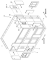
- FIG. 1 is an external perspective view of a building having an exterior wall structure according to an embodiment of the present invention.
- FIG. 2 is a front view of the building of FIG. 1 in the direction of the first beam.
- FIG. 2 is a schematic perspective view of a bracket and a rail.
- FIG. 13 is an explanatory diagram showing a construction example of fixing a rail to a bracket.
- 13A and 13B are diagrams showing a fixing structure between the bracket and the rail.
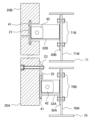
- a diagram showing the mounting positions of the end brackets and intermediate brackets on a building. 4 is a partially enlarged cross-sectional view showing the mounting portion of the bracket, rail, and exterior wall panel.
- FIG. FIG. 4 is a perspective view showing the fitting state of the end bracket and the rail.
- FIG. 4 is a perspective view showing a fitted state of the intermediate bracket and the rail.
- FIG. 1 is a diagram showing an example in which the exterior wall structure according to this embodiment is applied to a concrete building.
- FIG. 1 is a perspective view of the exterior of a building having an exterior wall structure according to this embodiment
- Fig. 2 is a front view of the first beam side of the building in Fig. 1.
- the building 1 shown in Figure 1 is constructed with a rigid-frame structure that uses columns 2 and beams 3 to form the framework.
- the building 1 is shown as having three floors, but the number of floors is not limited to this.
- the exterior wall structure 10 has at least one rail 40 attached to the framework for each floor, and multiple exterior wall panels are slid horizontally along the rail 40 to form the exterior wall.
- each arrow indicates the sliding direction.
- first beam side 4 of the building four exterior wall panels 20c-1, 20c-2, 20c-3, 20c-4 are arranged horizontally on the third floor to form the exterior wall of the third floor.
- first beam side 4 four panels are arranged horizontally for each floor, and these are stacked for three floors, i.e., three layers, to form the exterior wall using a total of 12 exterior wall panels.
- Exterior wall panels 20c-2 and 20c-4 are formed as wall panels having windows 28.
- multiple brackets 30a-1, 30a-2 are fixed at intervals along the horizontal direction below the first floor 5 of the structure, supporting rail 40a.
- Multiple brackets 30b-1, 30b-2 are fixed at intervals along the horizontal direction between the first floor ceiling and the second floor 6 of the structure, supporting rail 40b.
- Multiple brackets 30c-1, 30c-2 are fixed at intervals along the horizontal direction between the second floor ceiling and the third floor 7 of the structure, supporting rail 40c.
- Multiple brackets 30d-1, 30d-2 are fixed at intervals along the horizontal direction between the third floor ceiling and the rooftop floor 8 of the structure, supporting rail 40d.
- the exterior wall panels 20a-1, 20a-2, and 20a-3 that make up the exterior wall of the first floor are slid into position along the rails 40a and 40b.
- the exterior wall panels 20b-1, 20b-2, and 20b-3 that make up the exterior wall of the second floor are slid into position along the rails 40b and 40c.
- the exterior wall panels 20c-1, 20c-2, and 20c-3 that make up the exterior wall of the third floor are slid into position along the rails 40c and 40d.
- Each of the exterior wall panels 20a-1, 20a-2, 20a-3, ..., 20c-2, 20c-3 has a fitting structure for engaging with each of the rails 40a, 40b, 40c.
- Figure 3 is a schematic perspective view of the bracket and rail.
- Figure 4 is an explanatory diagram showing an example of how to fix the rail to the bracket.
- Figure 5 is a diagram showing the fixing structure between the bracket and the rail.
- the bracket 30 in FIG. 3 has a rectangular flange 31 and an L-shaped piece 32 that protrudes from the surface of the flange 31 that faces the rail 40.
- Bolt holes 33 are formed in the four corners of the flange 31.
- a bolt hole 34 is formed in the end of the L-shaped piece 32 opposite the flange 31.
- the rail 40 has a rail body 41 made of a long plate-like member, and a plate-like protruding piece 42 that protrudes from the surface of the rail body 41 facing the bracket 30.
- a bolt hole 44 is formed in the protruding piece 42.
- the rail body 41 has at least one, and preferably multiple, protruding pieces 42 spaced apart along the longitudinal direction.
- the rail 40 and bracket 30 are fitted together by abutting the rail body 41 against the L-shaped piece 32 while aligning the bolt holes 44 and 34.
- the rail 40 is connected to the bracket 30 by fastening the bolt holes 44 and 34 with bolts 91 and nuts 92 and 93. This fixes the rail 40 to the frame via the bracket 30.
- the brackets 30 include end brackets 30A used at the upper and lower ends of the exterior walls, and intermediate brackets 30B used on intermediate floors where the wall panels are continuous in the vertical direction.
- the end brackets 30A are brackets for supporting the rails 40 that engage with the hooks 22.
- the intermediate brackets 30B are brackets for supporting the rails 40 that are inserted into the grooves 21. Therefore, the L-shaped piece 32A of the end brackets 30A is formed shorter than the L-shaped piece 32B of the intermediate brackets 30B.
- Figure 6 is a diagram showing the mounting positions of the end bracket and intermediate bracket on a building.
- Figure 7 is a partially enlarged cross-sectional view showing the mounting portions of the bracket, rail, and exterior wall panel.
- Figure 8 is a perspective view showing the mating state of the end bracket and rail.
- Figure 9 is a perspective view showing the mating state of the intermediate bracket and rail.
- end bracket 30A is fixed to web 70w of H-shaped steel 70 supporting first floor 5 using bolt 70B.
- end bracket 30A is fixed to web 72w of H-shaped steel 72 supporting rooftop floor 8 using bolt 72B.
- intermediate bracket 30B is fixed to the web 71w of the H-shaped steel 71 that supports the second floor 7 using bolts 71B.
- the lower end of the exterior wall panel 20A on the first floor protrudes below the first floor floor 5. Therefore, the lower end of the exterior wall panel 20A is provided with a hook 22 as an interlocking structure.
- the upper end of the exterior wall panel 20B that constitutes the exterior wall of the top floor is provided with a hook 22 as an interlocking structure so that it protrudes above the roof floor 8 of the building 1.
- two hooks 22, 22 are provided horizontally spaced apart on each of the exterior wall panels 20A, 20B.
- the rail body 41 fixed to the end bracket 30A is hooked onto the hooks 22, 22 of the exterior wall panel 20A. Then, if necessary, the rail body 41 is slid along the longitudinal direction. This allows the exterior wall panel 20A to be attached to the frame. The same is true for the exterior wall panel 20B.
- grooves 21 into which the rails 40 are inserted are formed as fitting structures.
- the grooves 21 are formed as recesses into which the rail main body 41 can be inserted in the horizontal direction.
- the rail body 41 fixed to the intermediate bracket 30B is fitted into the groove 21 of the exterior wall panel 20A. Then, if necessary, the rail body 41 is slid along the longitudinal direction. This allows the exterior wall panel 20A to be attached to the frame. The same is true for the exterior wall panel 20B.
- the rail 40 is accommodated in the groove 21 formed on the upper end surface of the first floor exterior wall panel 20A and the lower end surface of the second floor exterior wall panel 20B, making it easier for the upper end surface of the first floor exterior wall panel 20A and the second floor exterior wall panel 20B to come into contact.
- the hooks 22 are provided protruding from the inner surfaces of the exterior wall panels 20A and 20B toward the structure. Meanwhile, the grooves 21 are formed within the wall thickness of the exterior wall panels 20A and 20B. Therefore, the hooks 22 engage with the rails 40 at a distance at least closer to the structure side than the grooves 21.
- FIG. 10 shows an example of applying the exterior wall structure of this embodiment to a concrete building.
- end brackets 30A are fixed using anchors 84 to concrete floor 81, which forms the ground floor, and concrete floor 83, which forms the rooftop floor.
- Intermediate brackets 30B are fixed using anchors 84 to concrete floor 82, which forms the intermediate floor. The rest of the structure is the same as the architectural portion of the rigid frame structure described above.
- Step 1 A plurality of end brackets 30A or a plurality of intermediate brackets 30B are arranged horizontally at intervals and fixed to the main body.
- Step 2 Fix the rail 40 to the end bracket 30A or the intermediate bracket 30B.
- Step 3 The grooves 21 or hooks 22 of the exterior wall panels 20A, 20B are engaged with the rail body 41, and if necessary, the rail body 41 is slid in the axial direction.
- the multiple exterior wall panels 20A, 20B are sequentially slid horizontally and arranged. If it is necessary to arrange them vertically, the fitting structures of the exterior wall panels 20A, 20B are engaged and attached to the rail 40 of each floor.
- each exterior wall panel is supported by rails, there is no need to stack the exterior wall panels sequentially from the lower floors to the higher floors.
- the exterior wall panels on the second floor can be installed before the exterior wall panels on the first floor, which has the advantage of increasing the flexibility of the construction procedure.
- the exterior wall panels are not load-bearing walls. Therefore, by incorporating windows into the exterior wall panels, there is more freedom in the placement of the windows.
- the exterior wall panel may be attached using end brackets and hooks even at locations where the exterior wall panel abuts in the vertical direction.
- Exterior wall panels can also be attached to the ends of the building's height using intermediate brackets and grooves.
- each element such as hooks and brackets is not limited to the above.
Landscapes
- Engineering & Computer Science (AREA)
- Architecture (AREA)
- Physics & Mathematics (AREA)
- Electromagnetism (AREA)
- Civil Engineering (AREA)
- Structural Engineering (AREA)
- Finishing Walls (AREA)
Priority Applications (2)
| Application Number | Priority Date | Filing Date | Title |
|---|---|---|---|
| PCT/JP2022/036748 WO2024069950A1 (ja) | 2022-09-30 | 2022-09-30 | 建築物の外壁構造、その外壁構造を有する建築物、及び建築物の外壁施工方法 |
| JP2024549041A JPWO2024069950A1 (https=) | 2022-09-30 | 2022-09-30 |
Applications Claiming Priority (1)
| Application Number | Priority Date | Filing Date | Title |
|---|---|---|---|
| PCT/JP2022/036748 WO2024069950A1 (ja) | 2022-09-30 | 2022-09-30 | 建築物の外壁構造、その外壁構造を有する建築物、及び建築物の外壁施工方法 |
Publications (1)
| Publication Number | Publication Date |
|---|---|
| WO2024069950A1 true WO2024069950A1 (ja) | 2024-04-04 |
Family
ID=90476986
Family Applications (1)
| Application Number | Title | Priority Date | Filing Date |
|---|---|---|---|
| PCT/JP2022/036748 Ceased WO2024069950A1 (ja) | 2022-09-30 | 2022-09-30 | 建築物の外壁構造、その外壁構造を有する建築物、及び建築物の外壁施工方法 |
Country Status (2)
| Country | Link |
|---|---|
| JP (1) | JPWO2024069950A1 (https=) |
| WO (1) | WO2024069950A1 (https=) |
Citations (5)
| Publication number | Priority date | Publication date | Assignee | Title |
|---|---|---|---|---|
| JPS4925740A (https=) * | 1972-07-04 | 1974-03-07 | ||
| JPS5536547A (en) * | 1978-09-07 | 1980-03-14 | Nippon Steel Corp | Method of fitting wall panel |
| JPH0544284A (ja) * | 1991-08-15 | 1993-02-23 | Kubota Corp | 壁パネルの取付構造 |
| JPH06341184A (ja) * | 1994-04-21 | 1994-12-13 | Tomoe Corp | 既製パネルの取付工法 |
| JP2008127927A (ja) * | 2006-11-24 | 2008-06-05 | Toyota Motor Corp | 建物及びその建築方法 |
-
2022
- 2022-09-30 JP JP2024549041A patent/JPWO2024069950A1/ja active Pending
- 2022-09-30 WO PCT/JP2022/036748 patent/WO2024069950A1/ja not_active Ceased
Patent Citations (5)
| Publication number | Priority date | Publication date | Assignee | Title |
|---|---|---|---|---|
| JPS4925740A (https=) * | 1972-07-04 | 1974-03-07 | ||
| JPS5536547A (en) * | 1978-09-07 | 1980-03-14 | Nippon Steel Corp | Method of fitting wall panel |
| JPH0544284A (ja) * | 1991-08-15 | 1993-02-23 | Kubota Corp | 壁パネルの取付構造 |
| JPH06341184A (ja) * | 1994-04-21 | 1994-12-13 | Tomoe Corp | 既製パネルの取付工法 |
| JP2008127927A (ja) * | 2006-11-24 | 2008-06-05 | Toyota Motor Corp | 建物及びその建築方法 |
Also Published As
| Publication number | Publication date |
|---|---|
| JPWO2024069950A1 (https=) | 2024-04-04 |
Similar Documents
| Publication | Publication Date | Title |
|---|---|---|
| JP5833564B2 (ja) | 建築用パネル化構造システム | |
| RU2518580C2 (ru) | Сооружение, имеющее множество уровней и способ его возведения | |
| CN1276161C (zh) | 竖框部件和将多个竖框部件固定到多个建筑物锚固件上的方法 | |
| JP3782817B1 (ja) | スチールハウスの構造形式および構築方法 | |
| US20130104472A1 (en) | Structural infill wall panel module | |
| US20040255535A1 (en) | Multi-purpose construction assembly and method | |
| JP4748637B2 (ja) | 建物ユニットの接合構造 | |
| WO2024069950A1 (ja) | 建築物の外壁構造、その外壁構造を有する建築物、及び建築物の外壁施工方法 | |
| JP7156885B2 (ja) | 腰壁パネルの固定構造 | |
| JP5009759B2 (ja) | 建物の横架材と接続部材との接続構造及びユニット建物並びにその構築方法 | |
| JP7312660B2 (ja) | 外壁パネル取り付け補助具及び外壁パネル取り付け方法 | |
| JP2024519114A (ja) | かみ合わせ可能な壁補強パネル、壁補強アセンブリ、及び壁補強のための方法 | |
| JP5091580B2 (ja) | バルコニー床の支持構造 | |
| JP3145989U (ja) | 軽量構築物 | |
| JP7235192B2 (ja) | 天井面材の支持構造及びユニット建物 | |
| CN120592355A (zh) | 装配式钢结构建筑的alc墙体连接节点 | |
| JP7375237B2 (ja) | 耐震天井構造 | |
| JP2021031860A (ja) | ユニット建物 | |
| US12503849B2 (en) | Wall system with infilled cross-laminated timber panel | |
| JP7715029B2 (ja) | 天井の構造および転び止め金物 | |
| JP7457554B2 (ja) | 木造建物の床組構造 | |
| JP7799123B1 (ja) | トラス架構及びトラス架構の設置構造 | |
| JP7214025B1 (ja) | 柱と横架材との接合構造 | |
| JP7496219B2 (ja) | 建物ユニット調整治具の配置構造 | |
| JP7213089B2 (ja) | コーナーカバー、及び出隅柱とコーナーカバーの取り付け構造 |
Legal Events
| Date | Code | Title | Description |
|---|---|---|---|
| 121 | Ep: the epo has been informed by wipo that ep was designated in this application |
Ref document number: 22961009 Country of ref document: EP Kind code of ref document: A1 |
|
| NENP | Non-entry into the national phase |
Ref country code: DE |
|
| ENP | Entry into the national phase |
Ref document number: 2024549041 Country of ref document: JP Kind code of ref document: A |
|
| WWE | Wipo information: entry into national phase |
Ref document number: 2024549041 Country of ref document: JP |
|
| 122 | Ep: pct application non-entry in european phase |
Ref document number: 22961009 Country of ref document: EP Kind code of ref document: A1 |