WO2024069830A1 - 回転電機およびその製造方法 - Google Patents
回転電機およびその製造方法 Download PDFInfo
- Publication number
- WO2024069830A1 WO2024069830A1 PCT/JP2022/036342 JP2022036342W WO2024069830A1 WO 2024069830 A1 WO2024069830 A1 WO 2024069830A1 JP 2022036342 W JP2022036342 W JP 2022036342W WO 2024069830 A1 WO2024069830 A1 WO 2024069830A1
- Authority
- WO
- WIPO (PCT)
- Prior art keywords
- circuit board
- board
- connector
- electric machine
- rotating electric
- Prior art date
- Legal status (The legal status is an assumption and is not a legal conclusion. Google has not performed a legal analysis and makes no representation as to the accuracy of the status listed.)
- Ceased
Links
Images







Classifications
-
- H—ELECTRICITY
- H02—GENERATION; CONVERSION OR DISTRIBUTION OF ELECTRIC POWER
- H02K—DYNAMO-ELECTRIC MACHINES
- H02K11/00—Structural association of dynamo-electric machines with electric components or with devices for shielding, monitoring or protection
- H02K11/30—Structural association with control circuits or drive circuits
-
- H—ELECTRICITY
- H02—GENERATION; CONVERSION OR DISTRIBUTION OF ELECTRIC POWER
- H02K—DYNAMO-ELECTRIC MACHINES
- H02K11/00—Structural association of dynamo-electric machines with electric components or with devices for shielding, monitoring or protection
- H02K11/30—Structural association with control circuits or drive circuits
- H02K11/33—Drive circuits, e.g. power electronics
-
- H—ELECTRICITY
- H02—GENERATION; CONVERSION OR DISTRIBUTION OF ELECTRIC POWER
- H02K—DYNAMO-ELECTRIC MACHINES
- H02K3/00—Details of windings
- H02K3/46—Fastening of windings on the stator or rotor structure
- H02K3/50—Fastening of winding heads, equalising connectors, or connections thereto
-
- H—ELECTRICITY
- H02—GENERATION; CONVERSION OR DISTRIBUTION OF ELECTRIC POWER
- H02K—DYNAMO-ELECTRIC MACHINES
- H02K5/00—Casings; Enclosures; Supports
- H02K5/04—Casings or enclosures characterised by the shape, form or construction thereof
- H02K5/15—Mounting arrangements for bearing-shields or end plates
-
- H—ELECTRICITY
- H02—GENERATION; CONVERSION OR DISTRIBUTION OF ELECTRIC POWER
- H02K—DYNAMO-ELECTRIC MACHINES
- H02K5/00—Casings; Enclosures; Supports
- H02K5/04—Casings or enclosures characterised by the shape, form or construction thereof
- H02K5/22—Auxiliary parts of casings not covered by groups H02K5/06-H02K5/20, e.g. shaped to form connection boxes or terminal boxes
-
- H—ELECTRICITY
- H02—GENERATION; CONVERSION OR DISTRIBUTION OF ELECTRIC POWER
- H02K—DYNAMO-ELECTRIC MACHINES
- H02K5/00—Casings; Enclosures; Supports
- H02K5/04—Casings or enclosures characterised by the shape, form or construction thereof
- H02K5/22—Auxiliary parts of casings not covered by groups H02K5/06-H02K5/20, e.g. shaped to form connection boxes or terminal boxes
- H02K5/225—Terminal boxes or connection arrangements
-
- H—ELECTRICITY
- H02—GENERATION; CONVERSION OR DISTRIBUTION OF ELECTRIC POWER
- H02K—DYNAMO-ELECTRIC MACHINES
- H02K9/00—Arrangements for cooling or ventilating
- H02K9/22—Arrangements for cooling or ventilating by solid heat conducting material embedded in, or arranged in contact with, the stator or rotor, e.g. heat bridges
- H02K9/227—Heat sinks
-
- H—ELECTRICITY
- H05—ELECTRIC TECHNIQUES NOT OTHERWISE PROVIDED FOR
- H05K—PRINTED CIRCUITS; CASINGS OR CONSTRUCTIONAL DETAILS OF ELECTRIC APPARATUS; MANUFACTURE OF ASSEMBLAGES OF ELECTRICAL COMPONENTS
- H05K7/00—Constructional details common to different types of electric apparatus
- H05K7/20—Modifications to facilitate cooling, ventilating, or heating
- H05K7/2089—Modifications to facilitate cooling, ventilating, or heating for power electronics, e.g. for inverters for controlling motor
- H05K7/209—Heat transfer by conduction from internal heat source to heat radiating structure
-
- H—ELECTRICITY
- H02—GENERATION; CONVERSION OR DISTRIBUTION OF ELECTRIC POWER
- H02K—DYNAMO-ELECTRIC MACHINES
- H02K11/00—Structural association of dynamo-electric machines with electric components or with devices for shielding, monitoring or protection
- H02K11/20—Structural association of dynamo-electric machines with electric components or with devices for shielding, monitoring or protection for measuring, monitoring, testing, protecting or switching
- H02K11/21—Devices for sensing speed or position, or actuated thereby
- H02K11/215—Magnetic effect devices, e.g. Hall-effect or magneto-resistive elements
-
- H—ELECTRICITY
- H02—GENERATION; CONVERSION OR DISTRIBUTION OF ELECTRIC POWER
- H02K—DYNAMO-ELECTRIC MACHINES
- H02K2203/00—Specific aspects not provided for in the other groups of this subclass relating to the windings
- H02K2203/06—Machines characterised by the wiring leads, i.e. conducting wires for connecting the winding terminations
-
- H—ELECTRICITY
- H02—GENERATION; CONVERSION OR DISTRIBUTION OF ELECTRIC POWER
- H02K—DYNAMO-ELECTRIC MACHINES
- H02K2211/00—Specific aspects not provided for in the other groups of this subclass relating to measuring or protective devices or electric components
- H02K2211/03—Machines characterised by circuit boards, e.g. pcb
Definitions
- This disclosure relates to a rotating electric machine and a manufacturing method thereof.
- the rotating electric machine disclosed in Patent Document 1 has a motor with a rotating shaft and a control unit that controls the motor.
- the control unit includes a first circuit board and a second circuit board arranged side by side in the axial direction of the rotating shaft, a spacer provided between the first circuit board and the second circuit board, and a connector assembly connected to the first and second circuit boards.
- the connector assembly, the second circuit board, the spacer, and the first circuit board are arranged in this order in the axial direction, and a shared fixing member is inserted through the connector assembly, the second circuit board, the spacer, and the first circuit board.
- the connector assembly, the second circuit board, the spacer, and the first circuit board are fixed to the heat sink by fixing an end of the shared fixing member to the heat sink.
- the first circuit board and the second circuit board cannot be fixed until they are fixed with the shared fixing member, making it difficult to assemble the first circuit board and the second circuit board to the heat sink with high precision. If the first circuit board and the second circuit board are temporarily fixed to the heat sink one by one before being fixed with the shared fixing member in order to improve assembly precision, the manufacture of the rotating electric machine becomes complicated and the manufacturing costs increase.
- the present disclosure has been made to solve the problems described above, and aims to provide a rotating electric machine and a manufacturing method thereof that allows the first circuit board and the second circuit board to be assembled with high precision and that can be manufactured easily and at low cost.
- the rotating electric machine includes a motor having a rotating shaft and a control unit for controlling the motor, the control unit includes a board unit having a first circuit board and a second circuit board, a holding member disposed between the first circuit board and the second circuit board and holding the first circuit board and the second circuit board, a heat sink disposed between the motor and the board unit so as to face the first circuit board in the axial direction of the rotating shaft, and a fastening member for fixing the board unit to the heat sink, the holding member having a base, a first locking portion connected to the base and locking the first circuit board from a second surface of the first circuit board opposite to a first surface facing the base, and a second locking portion connected to the base and locking the second circuit board from a fourth surface of the second circuit board opposite to a third surface facing the base, the fastening member penetrating the board unit in the axial direction and fastened to the heat sink.
- the manufacturing method of the rotating electric machine according to the present disclosure includes a board unit assembly process in which a first circuit board and a second circuit board are held by a holding member to assemble a board unit, and a board unit fixing process in which a fastening member is passed through the board unit in the axial direction of the rotating shaft of the motor and the fastening member is fastened to the heat sink to fix the board unit to the heat sink.
- This disclosure provides a rotating electric machine and a manufacturing method thereof that allows the first circuit board and the second circuit board to be assembled with high precision and that can be manufactured easily and at low cost.
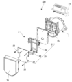
- FIG. 1 is an exploded perspective view of a rotating electric machine according to a first embodiment; 1 is a schematic cross-sectional view of a rotating electric machine according to a first embodiment.
- FIG. 2 is a perspective view of a first circuit board according to the first embodiment.
- FIG. 4 is a perspective view of a second circuit board according to the first embodiment.
- FIG. 2 is a perspective view of a holding member according to the first embodiment.
- FIG. 2 is a perspective view of a substrate unit according to the first embodiment.
- FIG. 2 is a perspective view of a heat sink according to the first embodiment.
- 1 is a perspective view of a connector according to a first embodiment.
- FIG. 4A to 4C are diagrams illustrating a manufacturing method of a rotating electric machine in the first embodiment.
- 4A to 4C are diagrams illustrating a manufacturing method of a rotating electric machine in the first embodiment.
- 4A to 4C are diagrams illustrating a manufacturing method of a rotating electric machine in the first embodiment.
- 4A to 4C are diagrams illustrating a manufacturing method of a rotating electric machine in the first embodiment.
- 4A to 4C are diagrams illustrating a manufacturing method of a rotating electric machine in the first embodiment.
- 4A to 4C are diagrams illustrating a manufacturing method of a rotating electric machine in the first embodiment.
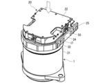
- 11 is a perspective view of an intermediate structure of a rotating electric machine according to a second embodiment, as viewed from below.
- FIG. 11 is a cross-sectional view taken along line AA in FIG. 10.
- FIG. 11 is a perspective view of a first circuit board according to a second embodiment.
- FIG. 11 is a perspective view of a second circuit board according to the second embodiment.
- FIG. 11 is a perspective view of a holding member according to a second embodiment.
- FIG. 13 is a perspective view of a holding member in a modified example of the second embodiment.
- FIG. 11 is a schematic cross-sectional view of a rotating electric machine according to a third embodiment.
- Fig. 1 is an exploded perspective view of a rotating electric machine 100 according to the first embodiment.
- Fig. 2 is a schematic cross-sectional view of the rotating electric machine 100.
- the rotating electric machine 100 includes a multi-phase winding type motor 1 and a control unit 2 that controls the motor 1.
- the control unit 2 includes a first circuit board 21, a second circuit board 22, an inter-board connector 23, a holding member 24, a heat sink 25, a fastening member 26, and a connector assembly 27.
- the motor 1 is mainly composed of a rotating shaft 11, a rotor 12, a stator 13, a motor case 14, an armature winding 15, an annular wiring section 16, a wiring terminal 17, and first and second bearings 18a, 18b.
- the direction in which the central axis O of the rotating shaft 11 of the motor 1 extends is sometimes referred to as the axial direction.
- the motor 1 and the control unit 2 are aligned in the axial direction.
- the side where the control unit 2 is located is sometimes referred to as the upper side
- the side where the motor 1 is located is sometimes referred to as the lower side.
- Viewing from the axial direction is sometimes referred to as a planar view.
- the direction that intersects with the central axis O is sometimes referred to as the radial direction
- the direction going around the central axis O is sometimes referred to as the circumferential direction.
- the rotating shaft 11, the rotor 12, and the stator 13 are arranged coaxially.
- the rotating shaft 11 has an input end 11a located at an upper portion and an output end 11b located at a lower portion.
- a driven object e.g., a steering system of a vehicle
- the rotor 12 is fixed to the rotating shaft 11.
- a plurality of pairs of permanent magnets (not shown) are arranged on the outer circumferential surface of the rotor 12. These permanent magnets form field poles.
- the stator 13 is provided to surround the outer periphery of the rotor 12.
- An air gap is formed between the outer periphery of the rotor 12 and the inner periphery of the stator 13. The air gap is formed over the entire circumference in the circumferential direction.
- the motor case 14 houses the rotating shaft 11, rotor 12, and stator 13.
- the motor case 14 has a cylindrical portion 14a and a bottom portion 14b.
- the cylindrical portion 14a covers the stator 13 from the outer periphery.
- the stator 13 is fixed to the inner surface of the cylindrical portion 14a by shrink fitting or press fitting.
- the bottom portion 14b covers the lower end of the cylindrical portion 14a.
- An output side shaft through hole 14c, through which the rotating shaft 11 is inserted, is formed in the center of the bottom portion 14b in a plan view.
- the upper end of the cylindrical portion 14a is covered by the heat sink 25 of the control unit 2.
- the armature winding 15 is wound around the stator 13.
- the armature winding 15 includes a U-phase winding, a V-phase winding, and a W-phase winding.
- the annular wiring portion 16 is disposed above the stator 13.
- the annular wiring portion 16 is disposed adjacent to the armature winding 15.
- the annular wiring portion 16 is connected to an end of the armature winding 15 by TIG welding or the like.
- the wiring terminal 17 extends upward from the annular wiring portion 16, penetrating the heat sink 25.
- the wiring terminal 17 is electrically connected to an end of the armature winding 15 via the annular wiring portion 16.
- the wiring terminal 17 is composed of three conductors, and these three conductors are electrically connected to an end of the U-phase winding, an end of the V-phase winding, and an end of the W-phase winding of the armature winding 15, respectively.
- An upper end of the wiring terminal 17 is connected to a first circuit board 21 of the control unit 2.
- the input end 11a of the rotating shaft 11 is inserted into a first shaft through hole 61 formed in the heat sink 25.
- the output end 11b of the rotating shaft 11 is inserted into an output side shaft through hole 14c formed in the bottom 14b.
- a first bearing 18a is provided in the first shaft through hole 61.
- a second bearing 18b is provided in the output side shaft through hole 14c. The first bearing 18a and the second bearing 18b support the rotating shaft 11 so that it can rotate freely.
- a sensor magnet 19 is attached to the input end 11a of the rotating shaft 11.
- the sensor magnet 19 is fixed by press fitting to the end face of the input end 11a facing the axial direction.
- the sensor magnet 19 has one or more pairs of permanent magnets.
- the sensor magnet 19 rotates together with the rotating shaft 11. Therefore, the magnetic field generated by the sensor magnet 19 changes as the rotating shaft 11 rotates.
- the control unit 2 controls the motor 1. In the axial direction, the second circuit board 22, the holding member 24, the first circuit board 21, and the heat sink 25 are arranged in this order from the top.
- the first circuit board 21, the second circuit board 22, the board-to-board connector 23, and the holding member 24 form the board unit 20.
- the control unit 2 is covered from above by a cover 70.
- the cover 70 is attached to a heat sink 25.
- the board unit 20 (first circuit board 21, second circuit board 22, board-to-board connector 23, and holding member 24) is housed in a space surrounded by the cover 70 and the heat sink 25.
- the first circuit board 21 is disposed between the holding member 24 and the heat sink 25 in the axial direction.
- the first circuit board 21 has a first surface 21a and a second surface 21b.
- the first surface 21a is the upper surface of the first circuit board 21, and the second surface 21b is the lower surface of the first circuit board 21.
- the inverter circuit that drives the motor 1 is mounted on the first circuit board 21.
- the inverter circuit is composed of electronic components such as switching elements, shunt resistors, and smoothing capacitors.
- electronic components 28 which are heat-generating elements that generate heat when the motor 1 is driven, are preferably arranged on the second surface 21b of the first circuit board 21.
- the electronic components 28 are in contact with the upper surface of the heat sink 25 via thermal grease 29. Heat generated from the electronic components 28 is dissipated to the heat sink 25 via the thermal grease 29.
- the electronic components 28 may also be arranged on the first surface 21a of the first circuit board 21.
- FIG. 3 is a perspective view from above of the first circuit board 21.
- first direction D1 one direction in a plane along the first surface 21a of the first circuit board 21
- second direction D2 a direction perpendicular to the first direction D1 in the above plane.
- the first direction D1 and the second direction D2 are perpendicular to the axial direction.
- the first circuit board 21 is provided with a second shaft through hole 31, a motor terminal connection hole 32 (motor connection portion), a first fastening through hole 33, a first positioning through hole 34, a connector terminal connection hole 35 (first connector connection portion), and a connector positioning through hole 37.
- the second shaft through hole 31 passes through the first circuit board 21 in the axial direction.
- the second shaft through hole 31 is positioned so as to overlap with the output side shaft through hole 14c in a plan view.
- the input end 11a of the rotating shaft 11 is inserted into the second shaft through hole 31.
- the motor terminal connection holes 32 penetrate the first circuit board 21 in the axial direction.
- the motor terminal connection holes 32 are provided at the end of the first circuit board 21 in the second direction D2.
- the three motor terminal connection holes 32 are arranged side by side in the first direction D1.
- the three motor terminal connection holes 32 are respectively connected to the three conductors of the wiring terminal 17.
- the first fastening through holes 33 pass through the first circuit board 21 in the axial direction.
- the first fastening through holes 33 are provided on the outer edge of the first circuit board 21.
- a plurality of first fastening through holes 33 are provided on both ends of the first circuit board 21 in the first direction D1 and both ends of the second direction D2.
- the fastening members 26 are inserted into the first fastening through holes 33.
- the first positioning through hole 34 penetrates the first circuit board 21 in the axial direction.
- the first positioning through hole 34 is provided on the outer edge of the first circuit board 21.
- a pair of first positioning through holes 34 are provided on both ends of the first circuit board 21 in the second direction D2.
- a first positioning protrusion 55 of the retaining member 24, which will be described later, is inserted into the first positioning through hole 34.
- the connector terminal connection holes 35 penetrate the first circuit board 21 in the axial direction.
- the connector terminal connection holes 35 are provided at one end of the first circuit board 21 in the first direction D1.
- multiple connector terminal connection holes 35 are arranged side by side in the second direction D2.
- the connector terminal connection holes 35 are connected to press-fit terminals 74 of the connector assembly 27, which will be described later.
- the connector positioning through holes 37 penetrate the first circuit board 21 in the axial direction.
- the connector positioning through holes 37 are provided at one end of the first circuit board 21 in the first direction D1.
- a pair of connector positioning through holes 37 are provided so as to be positioned on both sides of the multiple connector terminal connection holes 35 in the second direction D2 when viewed from the first direction D1.
- a connector positioning protrusion 75 of the connector assembly 27, which will be described later, is inserted into the connector positioning through holes 37.
- the second circuit board 22 is disposed above the first circuit board 21.
- the second circuit board 22 has a third surface 22a and a fourth surface 22b.
- the third surface 22a is the lower surface of the second circuit board 22, and the fourth surface 22b is the upper surface of the second circuit board 22.
- a control circuit that controls the drive of the motor 1 is mounted on the second circuit board 22.
- the control circuit is composed of a microcontroller that calculates the drive control of the motor 1, a drive circuit used to control the switching elements, etc.
- a rotation sensor 30 is mounted on the third surface 22a of the second circuit board 22.
- the rotation sensor 30 is a magnetic sensor such as a magnetoresistive sensor (MR sensor) or a Hall sensor.
- the rotation sensor 30 is arranged coaxially with a sensor magnet 19 attached to the rotating shaft 11.
- the sensor magnet 19 and the rotation sensor 30 face each other across a gap.
- the rotation sensor 30 detects changes in the magnetic field from the permanent magnet of the sensor magnet 19, which rotates together with the rotating shaft 11, and converts it into an electrical signal.
- the sensor magnet 19 and the rotation sensor 30 detect the rotation angle of the rotating shaft 11. Note that a resolver, an optical sensor, etc. may also be used as the rotation sensor 30.
- FIG. 4 is a perspective view from above of the second circuit board 22. As shown in FIG. 4, the second circuit board 22 is provided with a second fastening through hole 41, a second positioning through hole 42, and a notch portion 43.
- the second fastening through holes 41 axially pass through the second circuit board 22.
- the second fastening through holes 41 are provided on the outer edge of the second circuit board 22.
- the multiple second fastening through holes 41 are arranged at positions that overlap the multiple first fastening through holes 33 in a plan view.
- the fastening members 26 are inserted into the second fastening through holes 41.
- the second positioning through holes 42 penetrate the second circuit board 22 in the axial direction.
- the second positioning through holes 42 are provided on the outer edge of the second circuit board 22.
- the pair of second positioning through holes 42 are arranged at positions overlapping the pair of first positioning through holes 34 in a plan view.
- the first positioning through holes 34 and the second positioning through holes 42 may be arranged at different positions in a plan view.
- a second positioning protrusion 56 of the retaining member 24, which will be described later, is inserted into the second positioning through holes 42.
- the cutout portions 43 are recessed inward from the edge of the second circuit board 22 in the second direction D2.
- a pair of cutout portions 43 are provided at both ends of the second circuit board 22 in the second direction D2.
- the cutout portions 43 are formed at positions that overlap the motor terminal connection holes 32 in a plan view. When the board unit 20 is viewed from the second circuit board 22 side along the axial direction, the cutout portions 43 expose the motor terminal connection holes 32.
- the length of the second circuit board 22 in the first direction D1 is shorter than the length of the first circuit board 21 in the first direction D1.
- the board-to-board connector 23 is disposed between the first circuit board 21 and the second circuit board 22 in the axial direction.
- the board-to-board connector 23 electrically connects the inverter circuit of the first circuit board 21 and the control circuit of the second circuit board 22.
- the board-to-board connector 23 is composed of a male connector mounted on the first circuit board 21 and a female connector mounted on the second circuit board 22. By fitting the male connector and the female connector into each other, the first circuit board 21 and the second circuit board 22 are electrically connected via the board-to-board connector 23. Note that a bent board or a connector whose terminal tips are press-fit shaped may be used as the board-to-board connector 23.
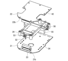
- the holding member 24 is disposed between the first circuit board 21 and the second circuit board 22 in the axial direction. With the first circuit board 21 and the second circuit board 22 electrically connected by the board-to-board connector 23, the holding member 24 holds the first circuit board 21 and the second circuit board 22, thereby assembling the board unit 20.
- Fig. 5 is a perspective view of the holding member 24 from above.
- Fig. 6 is a perspective view of the board unit 20 from below.
- the retaining member 24 has a base 51, a first locking portion 52, a second locking portion 53, a spacer 54, a first positioning protrusion 55, a second positioning protrusion 56, and a load transmission portion 57.
- the base 51 is frame-shaped with an internal space. Each member 52 to 57 of the holding member 24 is connected to the base 51.
- the internal space of the base 51 houses the electronic components mounted on the first circuit board 21 and the second circuit board 22, including the rotation sensor 30. This allows the internal space of the base 51 to be used to house the electronic components, making it possible to miniaturize the board unit 20.
- the first locking portion 52 locks the first circuit board 21 from the second surface 21b of the first circuit board 21 (i.e., the surface of the first circuit board 21 opposite the first surface 21a facing the base 51). As shown in FIG. 6, a plurality of first locking portions 52 are provided to surround the first circuit board 21.
- the first locking portion 52 has a first protrusion 52a extending downward from the base 51 (i.e., toward the first circuit board 21) and a first locking claw 52b located at the tip of the first protrusion 52a.
- the first locking claw 52b has a first locking surface facing upward. The first locking surface of the first locking claw 52b abuts against the second surface 21b of the first circuit board 21, thereby fixing the first circuit board 21 to the holding member 24 in the axial direction.
- the second locking portion 53 locks the second circuit board 22 from the fourth surface 22b of the second circuit board 22 (i.e., the surface of the second circuit board 22 opposite the third surface 22a facing the base 51).
- a plurality of second locking portions 53 are provided to surround the second circuit board 22.
- the second locking portion 53 has a second protrusion 53a extending upward from the base 51 (i.e., toward the second circuit board 22) and a second locking claw 53b located at the tip of the second protrusion 53a.
- the second locking claw 53b has a second locking surface facing downward. The second locking surface of the second locking claw 53b abuts against the fourth surface 22b of the second circuit board 22, thereby fixing the second circuit board 22 to the holding member 24 in the axial direction.
- the spacer 54 has a cylindrical shape extending in the axial direction.
- the spacers 54 are arranged at positions overlapping the first fastening through holes 33 in a plan view.
- One axial end of the spacer 54 abuts against the first circuit board 21, and the other axial end of the spacer 54 abuts against the second circuit board 22.
- the spacer 54 ensures a gap between the first circuit board 21 and the second circuit board 22.
- the spacer 54 has a third fastening through hole 54a that passes through the spacer 54 in the axial direction. The fastening member 26 is inserted through the third fastening through hole 54a.
- the second fastening through hole 41 of the second circuit board 22, the third fastening through hole 54a of the holding member 24, and the first fastening through hole 33 of the first circuit board 21 are arranged coaxially in this order from above.
- the second fastening through hole 41, the third fastening through hole 54a, and the first fastening through hole 33 are mutually connected.
- the second fastening through hole 41, the third fastening through hole 54a, and the first fastening through hole 33 are collectively referred to as the fastening through holes of the board unit 20.
- the first positioning protrusions 55 are cylindrical and extend in the axial direction. In this embodiment, a pair of first positioning protrusions 55 are provided corresponding to a pair of first positioning through holes 34. The first positioning protrusions 55 extend downward from the base 51. The first positioning protrusions 55 are inserted into the first positioning through holes 34. The first positioning protrusions 55 position the first circuit board 21 relative to the holding member 24. The height of the first positioning protrusions 55 is higher than the height of the first locking portions 52. In other words, the tip of the first positioning protrusions 55 is located lower than the tip of the first locking portions 52. Furthermore, the first positioning projections 55 are fitted into fitting holes 64 of the heat sink 25, which will be described later. This allows the board unit 20 to be positioned relative to the heat sink 25.
- the second positioning protrusions 56 are cylindrical and extend in the axial direction.
- a pair of second positioning protrusions 56 are provided corresponding to a pair of second positioning through holes 42.
- the second positioning protrusions 56 extend upward from the base 51.
- the second positioning protrusions 56 are inserted into the second positioning through holes 42.
- the second positioning protrusions 56 position the second circuit board 22 relative to the holding member 24.
- the height of the second positioning protrusions 56 is higher than the height of the second locking portions 53. That is, the tip of the second positioning protrusions 56 is located higher than the tip of the second locking portions 53.
- the first positioning protrusion 55 and the second positioning protrusion 56 are disposed at positions that overlap in a plan view. However, the first positioning protrusion 55 and the second positioning protrusion 56 may be disposed at different positions in a plan view.
- the load transmission part 57 is disposed at a position overlapping the heat dissipation grease 29 in a plan view.
- the load transmission part 57 has a first contact part 57a that contacts the first circuit board 21, a second contact part 57b that contacts the second circuit board 22, and a connection part 57c that connects the first contact part 57a and the second contact part 57b.
- the first contact part 57a is a protrusion provided on the lower surface of the base part 51.
- the second contact part 57b is a protrusion provided on the upper surface of the base part 51.
- the connection part 57c is a part of the base part 51.
- the heat sink 25 is disposed between the stator 13 and the board unit 20 (first circuit board 21) in the axial direction.
- the heat sink 25 is fitted into the cylindrical portion 14a of the motor case 14.
- the heat sink 25 covers the stator 13 from above.
- the heat sink 25 separates the space that houses the rotor 12 and stator 13 of the motor 1 from the space that houses the board unit 20 of the control unit 2.
- FIG. 7 is a perspective view of the heat sink 25 from above. As shown in FIG. 7, the heat sink 25 has a first shaft through hole 61, a motor terminal through hole 62, a fastening hole 63, and a fitting hole 64.
- the first shaft through hole 61 passes through the heat sink 25 in the axial direction.
- the first shaft through hole 61 is positioned so as to overlap with the output side shaft through hole 14c in a plan view.
- the input end 11a of the rotating shaft 11 is inserted into the first shaft through hole 61.
- the motor terminal through holes 62 penetrate the heat sink 25 in the axial direction.
- the motor terminal through holes 62 are provided at the end of the heat sink 25 in the second direction D2.
- the three motor terminal through holes 62 are arranged side by side in the first direction D1.
- the three motor terminal through holes 62 are arranged at positions overlapping with the three motor terminal connection holes 32 in a plan view.
- the three conductors of the wiring terminal 17 are inserted into the three motor terminal through holes 62, respectively.
- the size of the motor terminal through holes 62 is larger than the size of the wiring terminal 17. Therefore, when the wiring terminal 17 is inserted into the motor terminal through holes 62, contact between the wiring terminal 17 and the motor terminal through holes 62 is prevented.
- the fastening holes 63 are provided on the outer edge of the heat sink 25.
- the fastening holes 63 are recessed downward from the upper surface of the heat sink 25.
- the multiple fastening holes 63 are arranged at positions that overlap with the multiple first fastening through holes 33 in a plan view.
- the fastening members 26 are fastened to the fastening holes 63.
- the fitting holes 64 are provided on the outer edge of the heat sink 25.
- the fitting holes 64 are recessed downward from the upper surface of the heat sink 25.
- the pair of fitting holes 64 are positioned so as to overlap the pair of first positioning through holes 34 in a plan view.
- the first positioning protrusions 55 are fitted into the fitting holes 64.
- the fastening members 26 are used to fix the board unit 20 to the heat sink 25.
- multiple fastening members 26 are provided corresponding to multiple fastening through holes of the board unit 20.
- the fastening members 26 are inserted into the fastening through holes of the board unit 20 from the second circuit board 22 side and fastened to the fastening holes 63 of the heat sink 25. That is, the fastening members 26 pass axially through the board unit 20 and are fastened to the heat sink 25.
- the fastening member 26 is, for example, a screw.
- the fastening member 26 has a head that abuts against the second circuit board 22 and a shaft that extends in the axial direction from the head.
- the shaft of the fastening member 26 is inserted into a fastening through-hole of the board unit 20 and fastened to the fastening hole 63 of the heat sink 25.
- the outer shape of the head of the fastening member 26 is substantially the same as the outer shape of the spacer 54.
- the material of the fastening members 26 is preferably the same as the material of the spacer 54. In this case, it is possible to suppress changes in the fastening force of the fastening members 26 with respect to the first circuit board 21 and the second circuit board 22 due to temperature changes.
- the connector assembly 27 electrically connects the rotating electric machine 100 to an external power source, a sensor, etc.
- the connector assembly 27 is provided on the lower surface of the heat sink 25.
- the connector assembly 27 faces the first circuit board 21 via the heat sink 25.
- the connector assembly 27 is connected to the first circuit board 21. Note that in this embodiment, the connector assembly 27 is provided below the first circuit board 21, but the connector assembly 27 may also be provided above the first circuit board 21.
- FIG. 8 is a perspective view of the connector assembly 27. As shown in FIG. 8, the connector assembly 27 has a power terminal 71, a signal terminal 72, a connector holding portion 73, and a connector positioning protrusion 75.
- the power terminal 71 is connected to an external power source.
- the signal terminal 72 is connected to an external sensor, etc. Power from the external power source is supplied to the first circuit board 21 via the power terminal 71. Various signals from the external sensor, etc. are supplied to the first circuit board 21 via the signal terminal 72.
- the power terminal 71 and the signal terminal 72 are held by a connector holding portion 73.
- the ends of the power terminals 71 and the signal terminals 72 on the first circuit board 21 side are press-fit terminals 74 (first press-fit terminals).
- the press-fit terminals 74 extend from the connector holding portion 73 towards the first circuit board 21 side.
- the multiple press-fit terminals 74 are press-fitted into the multiple connector terminal connection holes 35 respectively.
- the press-fit terminals 74 come into contact with the conductive layer formed on the inner surface of the connector terminal connection holes 35, thereby electrically connecting the press-fit terminals 74 and the connector terminal connection holes 35.
- the connector positioning protrusions 75 are formed in a cylindrical shape. In this embodiment, a pair of connector positioning protrusions 75 are provided corresponding to a pair of connector positioning through holes 37.
- the connector positioning protrusions 75 extend from the connector holding portion 73 toward the first circuit board 21.
- the connector positioning protrusions 75 are inserted into the connector positioning through holes 37.
- the connector positioning protrusions 75 position the connector assembly 27 relative to the first circuit board 21.
- the height of the connector positioning protrusions 75 is greater than the height of the press-fit terminals 74. In other words, the tip of the connector positioning protrusions 75 is located closer to the first circuit board 21 than the tip of the press-fit terminals 74.
- the method for manufacturing the rotating electric machine 100 includes a board unit assembly process, a board unit fixing process, a connector attachment process, and a cover attachment process.
- the first circuit board 21 and the second circuit board 22 are held by the holding members 24 to assemble the board unit 20 .
- the first positioning protrusion 55 is inserted into the first positioning through-hole 34, and the first locking portion 52 locks the first circuit board 21 from the second surface 21b of the first circuit board 21. This fixes the first circuit board 21 to the holding member 24.
- the height of the first positioning protrusion 55 is greater than the height of the first locking portion 52. Therefore, with the first circuit board 21 positioned relative to the holding member 24 by the first positioning protrusion 55, the first circuit board 21 can be locked by the first locking portion 52.
- the second positioning protrusion 56 is inserted into the second positioning through-hole 42, and the second locking portion 53 locks the second circuit board 22 from the fourth surface 22b of the second circuit board 22. This fixes the second circuit board 22 to the holding member 24.
- the height of the second positioning protrusion 56 is greater than the height of the second locking portion 53. Therefore, with the second circuit board 22 positioned relative to the holding member 24 by the second positioning protrusion 56, the second circuit board 22 can be locked by the second locking portion 53.
- the male connector of the board-to-board connector 23 mounted on the first circuit board 21 with the female connector of the board-to-board connector 23 mounted on the second circuit board 22 the first circuit board 21 and the second circuit board 22 are electrically connected via the board-to-board connector 23.
- the board unit 20 is fixed to the heat sink 25 by fastening members 26 .
- the board unit 20 is disposed so that the first circuit board 21 faces the heat sink 25.
- the heat sink 25 is attached to the motor 1 in advance.
- the board unit 20 is placed on the upper surface of the heat sink 25.
- the first positioning protrusion 55 is fitted into the fitting hole 64 (see Fig. 9B) of the heat sink 25, thereby positioning the board unit 20 with respect to the heat sink 25.
- the wiring terminal 17 is inserted into the motor terminal connection hole 32.
- a load is applied to the second circuit board 22 toward the heat sink 25 (in the direction of the arrow in Fig.
- the connector assembly 27 is connected to the first circuit board 21 .
- the intermediate structure of the rotating electric machine 100 after the board unit fixing step is turned upside down.
- the connector assembly 27 is made to face the second surface 21b of the first circuit board 21.
- the connector positioning protrusions 75 (see Fig. 7) are inserted into the connector positioning through holes 37 of the first circuit board 21.
- a load is applied to the connector assembly 27 toward the first circuit board 21 (in the direction of the arrow in Fig. 9E), and the press-fit terminals 74 are press-fitted into the connector terminal connection holes 35 of the first circuit board 21.
- the height of the connector positioning protrusions 75 is greater than the height of the press-fit terminals 74.
- the press-fit terminals 74 can be press-fitted into the connector terminal connection holes 35.
- a pressing force is applied to the first circuit board 21.
- the pressing force applied to the first circuit board 21 can be received by the receiving jig. Therefore, distortion of the first circuit board 21 can be suppressed, and poor connection of the press-fit terminals 74 due to insufficient insertion of the press-fit terminals 74 into the connector terminal connection holes 35 can be prevented.
- the connector assembly 27 is screwed to the heat sink 25 using the second fastening members 77 .
- the rotating electric machine 100 includes the motor 1 having the rotating shaft 11 and the control unit 2 that controls the motor 1.
- the control unit 2 includes the board unit 20 having the first circuit board 21 and the second circuit board 22, and the holding member 24 that is arranged between the first circuit board 21 and the second circuit board 22 and holds the first circuit board 21 and the second circuit board 22, the heat sink 25 that is arranged between the motor 1 and the board unit 20 so as to face the first circuit board 21 in the axial direction, and the fastening member 26 that fixes the board unit 20 to the heat sink 25.
- the holding member 24 has a base 51, a first locking portion 52 that is connected to the base 51 and locks the first circuit board 21 from the second surface 21b of the first circuit board 21, and a second locking portion 53 that is connected to the base 51 and locks the second circuit board 22 from the fourth surface 22b of the second circuit board 22.
- the fastening member 26 passes axially through the board unit 20 and is fastened to the heat sink 25.
- the manufacturing method for the rotating electric machine 100 also includes a board unit assembly process in which the first circuit board 21 and the second circuit board 22 are held by the holding member 24 to assemble the board unit 20, and a board unit fixing process in which the fastening member 26 is passed through the board unit 20 in the axial direction and fastened to the heat sink 25, thereby fixing the board unit 20 to the heat sink 25.
- the first circuit board 21 and the second circuit board 22 are held by the holding members 24, thereby assembling the board unit 20. Thereafter, the board unit 20 is fixed to the heat sink 25 by the fastening members 26, thereby allowing the first circuit board 21 and the second circuit board 22 to be assembled to the heat sink 25 at once and with high accuracy. Since it is no longer necessary to assemble the circuit boards 21, 22 one by one, the manufacturing of the rotating electric machine 100 becomes easier. Furthermore, since the manufacturing line for the rotating electric machine 100 can be shared with the manufacturing line for a rotating electric machine in which a control unit is configured by a single circuit board, the manufacturing cost can be reduced.
- first circuit board 21 or second circuit board 22 when rotation sensor 30 that detects the rotation angle of rotating shaft 11 is mounted on first circuit board 21 or second circuit board 22, misalignment of first circuit board 21 and second circuit board 22 with respect to rotating shaft 11 may reduce the detection accuracy of rotation sensor 30. Since first circuit board 21 and second circuit board 22 can be assembled to heat sink 25 with high precision, misalignment of first circuit board 21 and second circuit board 22 with respect to rotating shaft 11 can be prevented, and a decrease in the detection accuracy of rotation sensor 30 can be prevented.
- the holding member 24 further includes a spacer 54 that is connected to the base portion 51, extends in the axial direction, and abuts against the first circuit board 21 and the second circuit board 22.
- the fastening member 26 is inserted through the spacer 54.
- the spacer 54 can ensure a gap between the first circuit board 21 and the second circuit board 22. This makes it easier to manufacture the rotating electric machine 100.
- the spacer 54 can be used to fix the board unit 20 to the heat sink 25. This eliminates the need to provide a separate fixing boss or the like for fixing the board unit 20 to the heat sink 25, thereby preventing an increase in the number of components and preventing a reduction in the mounting area for electronic components on the first circuit board 21 and the second circuit board 22.
- the retaining member 24 has a first positioning protrusion 55 connected to the base 51, which penetrates the first circuit board 21 in the axial direction and is inserted into the heat sink 25, and a second positioning protrusion 56 connected to the base 51 and which penetrates the second circuit board 22 in the axial direction.
- the first circuit board 21 and the second circuit board 22 can be positioned with respect to the heat sink 25 by the first positioning protrusions 55 and the second positioning protrusions 56. Therefore, the first circuit board 21 and the second circuit board 22 can be assembled with respect to the heat sink 25 with higher accuracy.
- thermal grease 29 is provided between the heat sink 25 and the electronic components 28.
- the holding member 24 is disposed at a position overlapping with the thermal grease 29 in a plan view, and further has a load transmission portion 57 that abuts against the first circuit board 21 and the second circuit board 22. According to this configuration, the load applied to the second circuit board 22 during the manufacture of the rotating motor 100 is transmitted to the first circuit board 21 via the load transmission part 57, thereby spreading out the heat dissipation grease 29 provided between the heat sink 25 and the electronic component 28.
- the motor 1 also includes a rotor 12 fixed to the rotating shaft 11, a stator 13 arranged on the outer periphery of the rotor 12, an armature winding 15 wound around the stator 13, and wiring terminals 17 electrically connected to the armature winding 15 and connected to the first circuit board 21.
- the first circuit board 21 has motor terminal connection holes 32 to which the wiring terminals 17 are connected.
- the second circuit board 22 has a cutout portion 43 that exposes the motor terminal connection holes 32 when the board unit 20 is viewed from the second circuit board 22 side along the axial direction. According to this configuration, for example, a connection tool for connecting the wiring terminal 17 to the motor terminal connection hole 32 can be brought close to the connection portion between the wiring terminal 17 and the motor terminal connection hole 32 via the notch portion 43. Therefore, the wiring terminal 17 can be easily connected to the motor terminal connection hole 32 via the notch portion 43. This makes it easier to manufacture the rotating electric machine 100.
- the outer shape of the head of the fastening member 26 is substantially the same as the outer shape of the spacer 54 . According to this configuration, the force generated when fastening the fastening member 26 can be reliably received by the spacer 54 while suppressing an increase in the space required for providing the head of the fastening member 26 .
- the control unit 2 further includes a connector assembly 27 having a press-fit terminal 74 connected to the first circuit board 21.
- the first circuit board 21 has a connector terminal connection hole 35 provided at one end of the first circuit board 21 in the first direction D1, to which the press-fit terminal 74 is connected.
- the connector assembly 27 can be easily connected to the first circuit board 21 by using the press-fit terminals 74. Therefore, the manufacturing of the rotating electric machine 100 becomes easier.
- a pressing force is applied to one end of the first circuit board 21 in the first direction D1. Because the one end of the first circuit board 21 is exposed from the second circuit board 22, a receiving jig for supporting the one end can be easily installed on the first circuit board 21. By receiving the pressing force applied to the first circuit board 21 with the receiving jig, distortion of the first circuit board 21 can be suppressed. Furthermore, poor connection of the press-fit terminals 74 due to insufficient insertion of the press-fit terminals 74 into the connector terminal connection holes 35 can be prevented.
- the connector assembly 27 has a connector positioning protrusion 75 that is inserted into the first circuit board 21 .
- the connector assembly 27 is positioned with respect to the first circuit board 21 by the connector positioning projections 75 , so that the press-fit terminals 74 can be connected to the connector terminal connection holes 35 more reliably.
- the tip of the connector positioning projection 75 is located closer to the first circuit board 21 than the tip of the press-fit terminal 74 . According to this configuration, the press-fit terminals 74 can be connected to the connector terminal connection holes 35 in a state in which the connector assembly 27 is positioned with respect to the first circuit board 21 by the connector positioning protrusions 75. Therefore, the press-fit terminals 74 can be connected to the connector terminal connection holes 35 more reliably.
- the board unit 20 further includes an inter-board connector 23 that electrically connects the first circuit board 21 and the second circuit board 22 .
- the first circuit board 21 and the second circuit board 22 can be easily electrically connected by the inter-board connector 23 .
- Embodiment 2 Next, a description will be given of a rotating electric machine 100A according to embodiment 2.
- the rotating electric machine 100A according to this embodiment has the same basic configuration as embodiment 1, so the following description will focus on the differences.
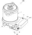
- Fig. 10 is a perspective view of the intermediate structure of the rotating electrical machine 100A as seen from below, and Fig. 11 is a cross-sectional view taken along line AA in Fig. 10.
- This embodiment differs from the first embodiment in that a connector assembly 27A is connected to a first circuit board 21A and a second circuit board 22A.
- the connector assembly 27A has a first press-fit terminal 81 connected to the first circuit board 21A and a second press-fit terminal 82 connected to the second circuit board 22A.
- the first press-fit terminal 81 is disposed in the center of the connector assembly 27A in the second direction D2.
- the second press-fit terminals 82 are disposed on both sides of the first press-fit terminal 81 in the second direction D2.
- the height of the second press-fit terminal 82 is greater than the height of the first press-fit terminal 81.
- the tip of the second press-fit terminal 82 is located closer to the second circuit board 22A than the tip of the first press-fit terminal 81.
- the length of the second circuit board 22A in the first direction D1 is approximately the same as the length of the first circuit board 21A in the first direction D1.
- the second circuit board 22A is arranged to overlap one end of the first circuit board 21 in the first direction D1.
- FIG. 12 is a perspective view from above of the first circuit board 21A.
- the first circuit board 21A is provided with a first connector terminal connection hole 38 (first connector connection portion) to which the first press-fit terminal 81 is connected, instead of the connector terminal connection hole 35.
- the first connector terminal connection hole 38 is provided at one end of the first circuit board 21A in the first direction D1.
- the first connector terminal connection hole 38 is disposed in the center of the first circuit board 21A in the second direction D2.
- the first circuit board 21A is provided with a connector terminal through hole 39 through which the second press-fit terminal 82 is inserted.
- the connector terminal through hole 39 is provided at one end of the first circuit board 21A in the first direction D1.
- the connector terminal through hole 39 is arranged on both sides of the first connector terminal connection hole 38 in the second direction D2.
- the size of the connector terminal through hole 39 is larger than the size of the second press-fit terminal 82. Therefore, when the second press-fit terminal 82 is inserted into the connector terminal through hole 39, contact between the second press-fit terminal 82 and the connector terminal through hole 39 is prevented.
- a cutout portion may be formed in the first circuit board 21A to prevent interference between the first circuit board 21A and the second press-fit terminal 82.
- FIG. 13 is a perspective view from above of the second circuit board 22A.
- the second circuit board 22A is provided with a second connector terminal connection hole 45 (second connector connection portion) to which the second press-fit terminal 82 is connected.
- the second connector terminal connection hole 45 is provided at one end of the second circuit board 22A in the first direction D1.
- the holding member 24A further includes a support portion 58.
- the support portion 58 is frame-shaped with an inner space.
- the support portion 58 is connected to one end of the base portion 51 in the first direction D1.
- the support portion 58 abuts against the first circuit board 21A and the second circuit board 22A.
- the support portion 58 is provided so as to surround the first connector terminal connection hole 38 of the first circuit board 21A.
- the support portion 58 supports the periphery of the first connector terminal connection hole 38 of the first circuit board 21A.
- the inner space of the support portion 58 accommodates the tip of the first press-fit terminal 81 connected to the first connector terminal connection hole 38. This prevents the first press-fit terminal 81 from coming into contact with the holding member 24A.
- the connector assembly 27A is connected to the first circuit board 21A and the second circuit board 22A.
- the other processes board unit assembly process, board unit fixing process, and cover attachment process
- cover attachment process cover attachment process
- the intermediate structure of the rotating electrical machine 100A after the board unit fixing process is turned upside down.
- the connector assembly 27A is placed facing the second surface 21b of the first circuit board 21A.
- the connector positioning protrusion 75 is inserted into the connector positioning through hole 37 of the first circuit board 21A.
- the second press-fit terminal 82 is inserted into the connector terminal through hole 39 of the first circuit board 21A.
- the receiving jig 200 is placed on the fourth surface 22b of the second circuit board 22A.
- a load is applied to the connector assembly 27A toward the first circuit board 21A.
- the first press-fit terminal 81 is pressed into the first connector terminal connection hole 38 of the first circuit board 21A
- the second press-fit terminal 82 is pressed into the second connector terminal connection hole 45 of the second circuit board 22A.
- the support portion 58 is provided between the first circuit board 21A and the second circuit board 22A so as to surround the first connector terminal connection hole 38. Therefore, the periphery of the first connector terminal connection hole 38 in the first circuit board 21A is supported by the support portion 58. Also, a receiving jig 200 is provided on the fourth surface 22b of the second circuit board 22A.
- the pressing force applied to the first circuit board 21A can be received by the receiving jig 200 via the support portion 58.
- the pressing force applied to the second circuit board 22A can be received by the receiving jig 200. Therefore, distortion of the first circuit board 21A can be suppressed, and a connection failure of the first press-fit terminal 81 caused by an insufficient insertion amount of the first press-fit terminal 81 into the first connector terminal connection hole 38 can be prevented.
- distortion of the second circuit board 22A can be suppressed, and a connection failure of the second press-fit terminal 82 caused by an insufficient insertion amount of the second press-fit terminal 82 into the second connector terminal connection hole 45 can be prevented.
- the connector assembly 27A is screwed to the heat sink 25 using the second fastening members 77.
- the connector assembly 27A further includes the second press-fit terminal 82 connected to the second circuit board 22A.
- the second circuit board 22A is provided at one end of the second circuit board 22A in the first direction D1 and includes the second connector terminal connection hole 45 to which the second press-fit terminal 82 is connected.
- the holding member 24A further includes a support portion 58 that is provided to surround the first connector terminal connection hole 38 when viewed in the axial direction and that abuts against the first circuit board 21A and the second circuit board 22A. According to this configuration, signals and the like from an external sensor can be directly input from connector assembly 27A to second circuit board 22A.
- the support portion 58 supports the periphery of the first connector terminal connection hole 38 in the first circuit board 21A.
- the pressing force can be received using the support portion 58, distortion of the first circuit board 21A and the second circuit board 22A can be suppressed.
- poor connection of the first press-fit terminal 81 caused by an insufficient insertion amount of the first press-fit terminal 81 into the first connector terminal connection hole 38 and poor connection of the second press-fit terminal 82 caused by an insufficient insertion amount of the second press-fit terminal 82 into the second connector terminal connection hole 45 can be prevented.
- FIG. 15 is a perspective view of a holding member 24A according to a modification of the second embodiment, seen from below.
- the holding member 24A further has a guide portion 84.
- the guide portion 84 has a guide through hole 84a penetrating the guide portion 84 in the axial direction.
- the multiple guide through holes 84a are arranged at positions overlapping the multiple second connector terminal connection holes 45 in a plan view.
- a lower end portion (end portion on one side) of the guide through hole 84a is formed in a tapered shape that gradually increases in diameter as it extends downward (to one side).
- the second press-fit terminal 82 is inserted into the guide through hole 84a from below (one side).
- the second press-fit terminal 82 can be smoothly inserted into the guide through hole 84a.
- the second press-fit terminal 82 is guided by the guide through hole 84a toward the second connector terminal connection hole 45 and is press-fitted into the second connector terminal connection hole 45.
- the size of the guide through hole 84a is larger than the size of the second press-fit terminal 82. Therefore, when the second press-fit terminal 82 is inserted into the guide through hole 84a, contact between the second press-fit terminal 82 and the guide through hole 84a is prevented.
- the holding member 24A has a guide portion 84 having a guide through hole 84a through which the second press-fit terminal 82 is inserted from one side.
- One end of the guide through hole 84a is formed in a tapered shape.
- the second press-fit terminal 82 is guided toward the second connector terminal connection hole 45 by the guide portion 84, so that the position of the second press-fit terminal 82 and the position of the second connector terminal connection hole 45 can be prevented from being misaligned. This allows the second press-fit terminal 82 to be reliably inserted into the second connector terminal connection hole 45.
- Embodiment 3 Next, a description will be given of a rotating electric machine 100B according to embodiment 3.
- the rotating electric machine 100B according to this embodiment has the same basic configuration as embodiment 1, so the following description will focus on the differences.
- Embodiment 3 differs from embodiment 1 in that the control unit 2 further includes a third circuit board 91, a second holding member 92, and a second board-to-board connector 93.
- the board unit 20A is composed of a first circuit board 21, a second circuit board 22, a board-to-board connector 23, a holding member 24, the third circuit board 91, the second holding member 92, and the second board-to-board connector 93.
- the third circuit board 91 is disposed above the second circuit board 22.
- the second board-to-board connector 93 is disposed between the second circuit board 22 and the third circuit board 91 in the axial direction.
- the second board-to-board connector 93 electrically connects the second circuit board 22 and the third circuit board 91.
- the second positioning protrusion 56 of the holding member 24 axially penetrates the second circuit board 22 and the third circuit board 91.
- the second positioning protrusion 56 positions the second circuit board 22 and the third circuit board 91 relative to the holding member 24.
- the second holding member 92 is disposed between the second circuit board 22 and the third circuit board 91 in the axial direction.
- the second holding member 92 holds the second circuit board 22 and the third circuit board 91.
- the second holding member 92 has a third locking portion (not shown) that locks the second circuit board 22 from the third surface 22a of the second circuit board 22, and a fourth locking portion (not shown) that locks the third circuit board 91 from the top surface of the third circuit board 91.
- the second holding member 92 has a second spacer 92a and a second load transmitting portion 92b.
- the second spacer 92a has a cylindrical shape extending in the axial direction.
- the second spacers 92a are arranged at positions overlapping the spacers 54 in a plan view.
- One axial end of the second spacers 92a abuts against the second circuit board 22, and the other axial end of the second spacers 92a abuts against the third circuit board 91.
- the second spacers 92a ensure a gap between the second circuit board 22 and the third circuit board 91.
- the second spacer 92a has a fourth fastening through hole that passes through the second spacer 92a in the axial direction.
- the fastening member 26 is inserted into the fourth fastening through hole.
- the second load transmission portion 92b is disposed at a position overlapping with the thermal grease 29 in a plan view.
- the second load transmission portion 92b abuts against the second circuit board 22 and the third circuit board 91.
- a load applied to the third circuit board 91 during the manufacture of the rotating electric machine 100 is transmitted to the first circuit board 21 via the second load transmission portion 92b, the second circuit board 22, and the load transmission portion 57.
- the first circuit board 21 is pressed toward the heat sink 25, and the thermal grease 29 applied between the heat sink 25 and the electronic components 28 mounted on the first circuit board 21 is spread.
- board unit 20A is assembled by holding first circuit board 21, second circuit board 22, and third circuit board 91 with holding member 24 and second holding member 92.
- second positioning protrusion 56 positions second circuit board 22 and third circuit board 91 with respect to holding member 24, so that board unit 20A can be assembled with the same accuracy as in the first embodiment.
- the other steps are the same as those in the first embodiment, so they will not be described here.
- the board unit 20A further has a third circuit board 91 and a second holding member 92 that is arranged between the second circuit board 22 and the third circuit board 91 and holds the second circuit board 22 and the third circuit board 91.
- the same effect as that of the first embodiment can be obtained. That is, the first circuit board 21, the second circuit board 22, and the third circuit board 91 are held by the holding member 24 and the second holding member 92, and the board unit 20A is assembled.
- the board unit 20A is fixed to the heat sink 25 by the fastening member 26, and the first circuit board 21, the second circuit board 22, and the third circuit board 91 can be assembled to the heat sink 25 at once and with high accuracy. Since it is not necessary to assemble the circuit boards 21, 22, and 91 one by one, the manufacturing of the rotating electric machine 100B is facilitated. In addition, the manufacturing line of the rotating electric machine 100B can be shared with the manufacturing line of the rotating electric machine in which the control unit is composed of one circuit board, and therefore the manufacturing cost can be reduced. The same effect can be obtained even when the control unit 2 has four or more circuit boards.
- the heat sink 25 may be formed integrally with the motor case 14 of the rotating electrical machine 100 .
- the fastening members 26 are not limited to screws as long as they can fasten the board unit 20 to the heat sink 25 .
- the number and arrangement of the fastening member 26, the first locking portion 52, the second locking portion 53, the spacer 54, the first positioning protrusion 55, and the second positioning protrusion 56 of the retaining member 24, and the press-fit terminal 74 of the connector assembly 27, etc. may be changed as appropriate depending on the specifications of the rotating motor 100.
Landscapes
- Engineering & Computer Science (AREA)
- Power Engineering (AREA)
- Microelectronics & Electronic Packaging (AREA)
- Physics & Mathematics (AREA)
- Thermal Sciences (AREA)
Priority Applications (5)
| Application Number | Priority Date | Filing Date | Title |
|---|---|---|---|
| KR1020257009378A KR20250054087A (ko) | 2022-09-29 | 2022-09-29 | 회전 전기 및 그 제조 방법 |
| EP22960892.2A EP4597806A4 (en) | 2022-09-29 | 2022-09-29 | ROTATING ELECTRIC MACHINE AND ITS MANUFACTURING METHOD |
| PCT/JP2022/036342 WO2024069830A1 (ja) | 2022-09-29 | 2022-09-29 | 回転電機およびその製造方法 |
| CN202280100040.6A CN119895704A (zh) | 2022-09-29 | 2022-09-29 | 旋转电机及其制造方法 |
| JP2024548942A JP7843852B2 (ja) | 2022-09-29 | 2022-09-29 | 回転電機およびその製造方法 |
Applications Claiming Priority (1)
| Application Number | Priority Date | Filing Date | Title |
|---|---|---|---|
| PCT/JP2022/036342 WO2024069830A1 (ja) | 2022-09-29 | 2022-09-29 | 回転電機およびその製造方法 |
Publications (1)
| Publication Number | Publication Date |
|---|---|
| WO2024069830A1 true WO2024069830A1 (ja) | 2024-04-04 |
Family
ID=90476844
Family Applications (1)
| Application Number | Title | Priority Date | Filing Date |
|---|---|---|---|
| PCT/JP2022/036342 Ceased WO2024069830A1 (ja) | 2022-09-29 | 2022-09-29 | 回転電機およびその製造方法 |
Country Status (5)
| Country | Link |
|---|---|
| EP (1) | EP4597806A4 (https=) |
| JP (1) | JP7843852B2 (https=) |
| KR (1) | KR20250054087A (https=) |
| CN (1) | CN119895704A (https=) |
| WO (1) | WO2024069830A1 (https=) |
Cited By (1)
| Publication number | Priority date | Publication date | Assignee | Title |
|---|---|---|---|---|
| US12494596B2 (en) * | 2021-07-28 | 2025-12-09 | Mitsubishi Electric Corporation | Circuit connection device, rotating electric machine device, and method for manufacturing circuit connection device |
Citations (2)
| Publication number | Priority date | Publication date | Assignee | Title |
|---|---|---|---|---|
| JP2017103848A (ja) * | 2015-11-30 | 2017-06-08 | 日本精工株式会社 | 電動機及びこれを備えた車載用装置、端子接続構造 |
| JP2020127334A (ja) | 2019-02-06 | 2020-08-20 | 日立オートモティブシステムズ株式会社 | 電動駆動装置 |
Family Cites Families (5)
| Publication number | Priority date | Publication date | Assignee | Title |
|---|---|---|---|---|
| JP4695010B2 (ja) * | 2006-04-19 | 2011-06-08 | 日本電産サンキョー株式会社 | 回路基板内蔵型ブラシレスモータ |
| JP6488198B2 (ja) * | 2015-05-29 | 2019-03-20 | 株式会社ミツバ | 制御装置 |
| JP6976882B2 (ja) * | 2018-02-23 | 2021-12-08 | サンデン・オートモーティブコンポーネント株式会社 | 電動圧縮機 |
| JP7231398B2 (ja) * | 2018-12-18 | 2023-03-01 | Kyb株式会社 | 回転電機 |
| JP7518922B2 (ja) * | 2020-12-28 | 2024-07-18 | 日立Astemo株式会社 | 電子制御装置 |
-
2022
- 2022-09-29 EP EP22960892.2A patent/EP4597806A4/en active Pending
- 2022-09-29 JP JP2024548942A patent/JP7843852B2/ja active Active
- 2022-09-29 KR KR1020257009378A patent/KR20250054087A/ko active Pending
- 2022-09-29 WO PCT/JP2022/036342 patent/WO2024069830A1/ja not_active Ceased
- 2022-09-29 CN CN202280100040.6A patent/CN119895704A/zh active Pending
Patent Citations (2)
| Publication number | Priority date | Publication date | Assignee | Title |
|---|---|---|---|---|
| JP2017103848A (ja) * | 2015-11-30 | 2017-06-08 | 日本精工株式会社 | 電動機及びこれを備えた車載用装置、端子接続構造 |
| JP2020127334A (ja) | 2019-02-06 | 2020-08-20 | 日立オートモティブシステムズ株式会社 | 電動駆動装置 |
Non-Patent Citations (1)
| Title |
|---|
| See also references of EP4597806A4 |
Cited By (1)
| Publication number | Priority date | Publication date | Assignee | Title |
|---|---|---|---|---|
| US12494596B2 (en) * | 2021-07-28 | 2025-12-09 | Mitsubishi Electric Corporation | Circuit connection device, rotating electric machine device, and method for manufacturing circuit connection device |
Also Published As
| Publication number | Publication date |
|---|---|
| CN119895704A (zh) | 2025-04-25 |
| JP7843852B2 (ja) | 2026-04-10 |
| KR20250054087A (ko) | 2025-04-22 |
| JPWO2024069830A1 (https=) | 2024-04-04 |
| EP4597806A1 (en) | 2025-08-06 |
| EP4597806A4 (en) | 2025-10-22 |
Similar Documents
| Publication | Publication Date | Title |
|---|---|---|
| US10559998B2 (en) | Motor and disk drive apparatus | |
| WO2018096710A1 (ja) | モータ及び電動パワーステアリング装置 | |
| WO2020241027A1 (ja) | 回転電機 | |
| WO2018029894A1 (ja) | モータ及び電動パワーステアリング装置 | |
| WO2013094086A1 (ja) | モータ制御ユニットおよびブラシレスモータ | |
| JPWO2020067255A1 (ja) | モータ | |
| JP7843852B2 (ja) | 回転電機およびその製造方法 | |
| JP7384709B2 (ja) | 電動パワーステアリング装置および製造方法 | |
| JP4582182B2 (ja) | 電動式パワーステアリング装置 | |
| US20110198952A1 (en) | Brushless dc motor | |
| JP2002325392A (ja) | ブラシレスモータとそのターミナル構造 | |
| WO2022153606A1 (ja) | バルブタイミングコントロール機構 | |
| JP7231398B2 (ja) | 回転電機 | |
| WO2018142844A1 (ja) | モータ | |
| JP7561985B2 (ja) | 電動機制御装置 | |
| JPWO2024069830A5 (https=) | ||
| JP7284578B2 (ja) | サーボモータ | |
| JP6969393B2 (ja) | モータ | |
| JP7471526B2 (ja) | 回路接続装置、回転電機装置、及び回路接続装置の製造方法 | |
| JP7599547B2 (ja) | 回路接続装置、回転電機装置および回路接続装置の製造方法 | |
| JP2025126946A (ja) | 回転電機 | |
| JP7442745B2 (ja) | 回路接続装置、回転電機装置、及び回路接続装置の製造方法 | |
| JP2023176291A (ja) | モータ | |
| JP2023007377A (ja) | 電子部品及び電子部品の製造方法 | |
| WO2023281905A1 (ja) | 電子部品及び電子部品の製造方法 |
Legal Events
| Date | Code | Title | Description |
|---|---|---|---|
| 121 | Ep: the epo has been informed by wipo that ep was designated in this application |
Ref document number: 22960892 Country of ref document: EP Kind code of ref document: A1 |
|
| ENP | Entry into the national phase |
Ref document number: 2024548942 Country of ref document: JP Kind code of ref document: A |
|
| WWE | Wipo information: entry into national phase |
Ref document number: 202280100040.6 Country of ref document: CN |
|
| WWE | Wipo information: entry into national phase |
Ref document number: 202527024437 Country of ref document: IN |
|
| ENP | Entry into the national phase |
Ref document number: 20257009378 Country of ref document: KR Kind code of ref document: A |
|
| WWE | Wipo information: entry into national phase |
Ref document number: 1020257009378 Country of ref document: KR |
|
| WWP | Wipo information: published in national office |
Ref document number: 1020257009378 Country of ref document: KR |
|
| WWP | Wipo information: published in national office |
Ref document number: 202280100040.6 Country of ref document: CN |
|
| WWE | Wipo information: entry into national phase |
Ref document number: 2022960892 Country of ref document: EP |
|
| NENP | Non-entry into the national phase |
Ref country code: DE |
|
| ENP | Entry into the national phase |
Ref document number: 2022960892 Country of ref document: EP Effective date: 20250429 |
|
| WWP | Wipo information: published in national office |
Ref document number: 202527024437 Country of ref document: IN |
|
| WWP | Wipo information: published in national office |
Ref document number: 2022960892 Country of ref document: EP |