WO2024063145A1 - 弁装置、膨張弁、弁装置の製造方法、及び膨張弁の製造方法 - Google Patents
弁装置、膨張弁、弁装置の製造方法、及び膨張弁の製造方法 Download PDFInfo
- Publication number
- WO2024063145A1 WO2024063145A1 PCT/JP2023/034327 JP2023034327W WO2024063145A1 WO 2024063145 A1 WO2024063145 A1 WO 2024063145A1 JP 2023034327 W JP2023034327 W JP 2023034327W WO 2024063145 A1 WO2024063145 A1 WO 2024063145A1
- Authority
- WO
- WIPO (PCT)
- Prior art keywords
- surface portion
- valve body
- valve
- flow path
- adjacent
- Prior art date
- Legal status (The legal status is an assumption and is not a legal conclusion. Google has not performed a legal analysis and makes no representation as to the accuracy of the status listed.)
- Ceased
Links
Images












Classifications
-
- F—MECHANICAL ENGINEERING; LIGHTING; HEATING; WEAPONS; BLASTING
- F16—ENGINEERING ELEMENTS AND UNITS; GENERAL MEASURES FOR PRODUCING AND MAINTAINING EFFECTIVE FUNCTIONING OF MACHINES OR INSTALLATIONS; THERMAL INSULATION IN GENERAL
- F16K—VALVES; TAPS; COCKS; ACTUATING-FLOATS; DEVICES FOR VENTING OR AERATING
- F16K27/00—Construction of housing; Use of materials therefor
- F16K27/02—Construction of housing; Use of materials therefor of lift valves
- F16K27/029—Electromagnetically actuated valves
-
- F—MECHANICAL ENGINEERING; LIGHTING; HEATING; WEAPONS; BLASTING
- F16—ENGINEERING ELEMENTS AND UNITS; GENERAL MEASURES FOR PRODUCING AND MAINTAINING EFFECTIVE FUNCTIONING OF MACHINES OR INSTALLATIONS; THERMAL INSULATION IN GENERAL
- F16K—VALVES; TAPS; COCKS; ACTUATING-FLOATS; DEVICES FOR VENTING OR AERATING
- F16K31/00—Actuating devices; Operating means; Releasing devices
- F16K31/02—Actuating devices; Operating means; Releasing devices electric; magnetic
- F16K31/06—Actuating devices; Operating means; Releasing devices electric; magnetic using a magnet, e.g. diaphragm valves, cutting off by means of a liquid
- F16K31/0644—One-way valve
- F16K31/0655—Lift valves
Definitions
- the present invention relates to a valve device, an expansion valve, a method for manufacturing a valve device, and a method for manufacturing an expansion valve.
- An expansion valve with a solenoid valve which is one type of valve device, is used, for example, in a refrigeration cycle having multiple evaporators connected in parallel, and has a function to control the degree of superheat of the refrigerant on the outlet side of the evaporator as well as a function to shut off the circuit in the refrigeration cycle.
- such an expansion valve with an electromagnetic valve includes a throttle passage that depressurizes and expands the high-pressure side refrigerant, and a valve that adjusts the opening degree of the throttle passage.
- the valve body has a power element that displaces the valve body, an outlet channel that supplies the decompressed and expanded refrigerant to the evaporator, and a solenoid valve that opens and closes the outlet channel.
- the valve body is formed, for example, by machining an intermediate product formed by extrusion molding an aluminum alloy to form channels, holes, and the like.
- a surface formed by extrusion molding is used as a mounting surface of the housing, it is difficult to ensure sufficient dimensional accuracy of the mounting portion. Therefore, by cutting the surface formed by extrusion molding, for example, with a milling cutter to form the mounting surface, sufficient dimensional accuracy of the mounting portion is ensured.
- one side of the valve body of an expansion valve with a solenoid valve is the mounting surface of the solenoid valve, but since the area of one side of the valve body is larger than the area required for installing the solenoid valve, If one side of the main body is entirely cut, there is a cost problem in that the machining time becomes longer and more material is removed during the machining, resulting in increased waste.
- Patent Document 2 it is also possible to form a mounting surface by processing only the range necessary for mounting the electromagnetic valve on one side of the valve body.
- a locally low mounting surface is formed on one side of the valve body by milling, for example, burrs will occur on the one side at a stepped portion between the mounting surface and a surface portion adjacent to the mounting surface.
- this burr can be removed by post-processing, the problem arises that the number of steps increases and the processing time increases.
- the present invention has been made in view of the above problems, and provides a valve device, an expansion valve, a method for manufacturing a valve device, and a method for manufacturing an expansion valve that can reduce manufacturing costs without increasing the number of manufacturing steps.
- the purpose is to provide
- the valve device of the present invention includes: In a valve device having a valve body, One side of the valve body includes a base surface portion formed by a predetermined cutting or grinding process and a flat surface to which an object to be fixed can be attached, and an adjacent base surface portion adjacent to at least a part of the edge of the base surface portion. Equipped with a The adjacent portion is not subjected to the predetermined cutting or grinding process, and has a shape that does not protrude with respect to the base surface in the normal direction of the base surface. It is characterized by
- the valve device of the present invention includes: In a valve device having a valve body, One side of the valve body has a base surface portion that is a flat surface to which an object to be fixed can be attached, and an adjacent surface portion adjacent to the base surface portion, The adjacent surface portion is located at the same position as the base surface portion in the normal direction of the base surface portion, or located further inward of the valve body than the base surface portion, The average surface roughness of the base surface portion is different from the average surface roughness of the adjacent surface portion, It is characterized by
- the expansion valve of the present invention includes: a valve chamber, an orifice formed on the upper surface of the valve chamber, a supply side channel communicating with the valve chamber and the outside and supplying refrigerant to the valve chamber, communicating with the orifice and the outside, and supplying the refrigerant from the orifice.
- valve body having a discharge side flow path for discharging the refrigerant to the outside, and a return flow path for flowing the refrigerant discharged from the discharge side flow path; a valve body disposed in the valve chamber; a power element that is provided on the upper surface of the valve body and generates a driving force that drives the valve body; an actuation rod that transmits the driving force of the power element to the valve body; a fixed object attached to one side of the valve body; Equipped with The supply side flow path extends from the front surface of the valve body to the valve chamber, The discharge side flow path extends from the back surface of the valve body to the orifice, The return flow path extends from the front surface to the back surface, The discharge side flow path is located above the supply side flow path, The return flow path is located above the discharge side flow path, The side surface is formed by performing a predetermined cutting or grinding process from a recess formed along the return flow path and from a lower end side of the side surface to the recess, and the object to be fixed is
- the method for manufacturing a valve device of the present invention includes: A first step of forming an intermediate product of a valve body from a raw material, wherein one side of the intermediate product includes an unprocessed base surface portion and an adjacent portion adjacent to at least a part of the edge of the unprocessed base surface portion.
- the method for manufacturing an expansion valve of the present invention includes: a valve chamber, an orifice formed on the upper surface of the valve chamber, a supply side channel communicating with the valve chamber and the outside and supplying refrigerant to the valve chamber, communicating with the orifice and the outside, and supplying the refrigerant from the orifice.
- valve body having a discharge side flow path for discharging the refrigerant to the outside, and a return flow path for flowing the refrigerant discharged from the discharge side flow path; a valve body disposed in the valve chamber; a power element that is provided on the upper surface of the valve body and generates a driving force that drives the valve body; an actuation rod that transmits the driving force of the power element to the valve body; a fixed object attached to one side of the valve body; Equipped with The supply side flow path extends from the front surface of the valve body to the valve chamber, The discharge side flow path extends from the back surface of the valve body to the orifice, The return flow path extends from the front surface to the back surface, The discharge side flow path is located above the supply side flow path, A method for manufacturing an expansion valve in which the return flow path is located above the discharge side flow path, A first step of forming an intermediate product of the valve body from a raw material, wherein one side of the intermediate product includes an unprocessed base surface portion and an adjacent portion adjacent to
- a valve device an expansion valve
- a method for manufacturing a valve device a method for manufacturing an expansion valve that can reduce manufacturing costs without increasing the number of manufacturing steps.
- FIG. 1 is a schematic cross-sectional view schematically showing an expansion valve with a solenoid valve in a first embodiment.
- FIG. 2 is a longitudinal cross-sectional view of the expansion valve with an electromagnetic valve in a cross section whose phase is shifted by 90 degrees around the axis L with respect to FIG.
- FIG. 3 is a cross-sectional view showing the configuration of FIG. 2 taken along line AA.
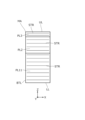
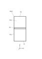
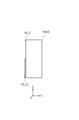
- FIG. 4A is a schematic diagram illustrating the manufacturing process of the valve body, and is a side view of the molded product after extrusion molding.
- FIG. 4B is a schematic diagram illustrating the manufacturing process of the valve body, and is a front view of the molded product after extrusion molding.
- FIG. 4A is a schematic diagram illustrating the manufacturing process of the valve body, and is a side view of the molded product after extrusion molding.
- FIG. 4B is a schematic diagram illustrating the manufacturing process of the valve body, and is a front view of the molded product after extrusion
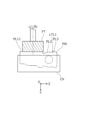
- FIG. 5A is a schematic diagram illustrating the manufacturing process of the valve body, and is a diagram showing the state during milling.
- FIG. 5B is a schematic diagram illustrating the manufacturing process of the valve body, and is a diagram showing the state during milling.
- FIG. 5C is a schematic diagram illustrating the manufacturing process of the valve body, and is a diagram showing the state during milling.
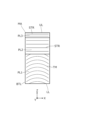
- FIG. 6A is a schematic diagram illustrating the manufacturing process of the valve body, and is a side view of the molded product after milling.
- FIG. 6B is a schematic diagram illustrating the manufacturing process of the valve body, and is a front view of the molded product after milling.
- FIG. 7 is a schematic diagram illustrating the manufacturing process of the valve body, and is a diagram showing the state during machining.
- FIG. 8A is a side view of a molded product according to a modified example after milling.
- FIG. 8B is a side view of the molded product according to the modified example after milling.
- FIG. 9A is a schematic diagram illustrating the manufacturing process of the molded product according to the first comparative example, and is a side view of the molded product after extrusion molding.
- FIG. 9B is a schematic diagram illustrating the manufacturing process of the molded product according to the first comparative example, and is a front view of the molded product after extrusion molding.
- FIG. 10A is a schematic diagram illustrating the manufacturing process of the molded product according to the first comparative example, and is a side view of the molded product after milling.
- FIG. 9A is a schematic diagram illustrating the manufacturing process of the molded product according to the first comparative example, and is a side view of the molded product after milling.
- FIG. 10B is a schematic diagram illustrating the manufacturing process of the molded product according to the first comparative example, and is a front view of the molded product after milling.
- FIG. 11A is a schematic diagram illustrating the manufacturing process of a molded product according to a second comparative example, and is a side view of the molded product after milling.
- FIG. 11B is a schematic diagram illustrating the manufacturing process of the molded product according to the second comparative example, and is a front view of the molded product after milling.
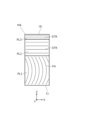
- FIG. 12A is a schematic diagram illustrating the manufacturing process of the valve body of the second embodiment, and is a side view of the molded product after extrusion molding.
- FIG. 12B is a schematic diagram illustrating the manufacturing process of the valve body of the second embodiment, and is a front view of the molded product after extrusion molding.
- FIG. 13A is a schematic diagram illustrating the manufacturing process of the valve body of the third embodiment, and is a side view of the molded product after extrusion molding.
- FIG. 13B is a schematic diagram illustrating the manufacturing process of the valve body of the third embodiment, and is a front view of the molded product after extrusion molding.
- FIG. 14A is a schematic diagram illustrating the manufacturing process of the valve body of the fourth embodiment, and is a rear view of the molded product after extrusion molding.
- FIG. 14B is a schematic diagram illustrating the manufacturing process of the valve body of the fourth embodiment, and is a left side view of the molded product after extrusion molding.
- FIG. 14C is a schematic diagram illustrating the manufacturing process of the valve body of the fourth embodiment, and is a front view of the molded product after extrusion molding.
- FIG. 15 is a schematic diagram illustrating the valve body of the fifth embodiment.
- the expansion valve ESV with a solenoid valve includes an expansion valve unit 1 and a solenoid valve unit 100, and the expansion valve unit 1 and the solenoid valve unit 100 commonly use a valve body 2.
- the vertical direction is set with the power element 8 side relative to the valve body 2 as the upper side
- the width direction is set as the direction in which the valve body 2 and the solenoid valve unit 100 are lined up among the directions perpendicular to the vertical direction.
- the direction perpendicular to both the vertical direction and the width direction is set as the front-back direction.
- FIG. 1 is a schematic cross-sectional view schematically showing an expansion valve ESV with a solenoid valve in this embodiment.
- the structure of the expansion valve unit 1 in the expansion valve ESV with electromagnetic valve will be explained.
- L be the axis of the valve body 2.
- the axis L refers to the center line of the actuating rod 5, that is, it is parallel to the vertical direction, and is a line passing through the center of the valve chamber VS, which will be described later.
- the expansion valve unit 1 includes a valve body 2 including a valve chamber VS, a valve body 3, a biasing device 4, an actuation rod 5, a ring spring 6, and a power element 8.
- L be the axis of the expansion valve unit 1.
- the power element 8 side with respect to the valve body 3 is assumed to be above, and the valve body 3 side with respect to the power element 8 is assumed to be below.
- the valve body 2 includes a first flow path 21, a second flow path 22, and a return flow path 23 extending from the front surface to the back surface of the valve body 2.
- the first flow path 21 is a supply side flow path extending from the front surface of the valve body 2 to the valve chamber VS, and a refrigerant (also referred to as fluid) is supplied to the valve chamber VS via the supply side flow path.
- the second flow path 22, together with the intermediate passage 221, constitutes a discharge side flow path extending from the back surface of the valve body 2 to the operating rod insertion hole 27. It is discharged outside the expansion valve via the side flow path.
- the discharge side flow path is located above the supply side flow path
- the return flow path is located above the discharge side flow path.
- the first flow path 21 and the valve chamber VS communicate with each other via a high pressure side flow path 112 and a low pressure side flow path 113 (FIG. 3), which will be described later.
- the valve body 2 includes an upper surface UL, a lower surface LL, a front surface FTL, a back surface BTL, a left side LTL, and a right side RTL.
- the valve body 2 is made of metal, for example.
- the upper surface UL and the lower surface LL are formed, for example, in a plane perpendicular to the vertical direction.
- the front surface FTL and the rear surface BTL are formed, for example, on a plane orthogonal to the front-rear direction.
- the left side LTL is an example of one side to which the solenoid valve unit 100 is fixed.
- One side is one of the outer surfaces of the valve body 2 along the axis of the valve body 2.
- the left side surface LTL has a first surface portion PL1 (base surface portion), a second surface portion PL2 (adjacent surface portion), and a third surface portion PL3 (another plane portion).
- the left side LTL is formed by performing a predetermined cutting or grinding process from the recess D formed along the return flow path 23 and from the lower end side of the left side LTL to the recess D.
- the first surface portion PL1 is a flat surface on which an object to be fixed can be attached.
- the first surface portion PL1 is a range on the left side surface LTL to which the solenoid valve unit 100 can be attached, and is formed into a flat surface.
- the area required for mounting the solenoid valve unit 100 is smaller than the area of the left side LTL.
- the first surface portion PL1 is formed, for example, in a plane perpendicular to the width direction.
- the first surface portion PL1 faces, for example, the valve chamber VS in the width direction, and is formed in the range from the middle part to the lower end in the vertical direction on the left side surface LTL.
- the first surface portion PL1 is formed by cutting in order to ensure sufficient dimensional accuracy of the circular opening 114, which is the attachment portion of the solenoid valve unit 100.
- the second surface portion PL2 is an adjacent portion adjacent to the first surface portion PL1.
- the second surface portion PL2 is a surface located more inward of the valve body 2 than the first surface portion PL1 in the normal direction of the first surface portion PL1.
- a surface located closer to the center of the valve body 2 than the first surface portion PL1 in the normal direction of the first surface portion PL1 is a surface located closer to the center of the valve body 2 than the first surface portion PL1.
- a surface located more inward of the valve body 2 than the first surface portion PL1 in the normal direction of the first surface portion PL1 is a surface lower than the first surface portion PL1.
- the second surface portion PL2 is the surface of the recess D along the return flow path 23, which will be described later.
- This recess D extends linearly from the front surface FTL of the valve body 2 to the rear surface BTL. That is, the cross-sectional shape of the recess D shown in FIG. 2 is substantially the same from the front surface FTL to the back surface BTL of the valve body 2.
- the length of the edge of the second surface portion PL2 on the first surface portion PL1 side is set to be equal to or longer than the length of the edge of the first surface portion PL1 on the second surface portion PL2 side.
- the edge of the second surface portion PL2 on the first surface portion PL1 side is the second surface portion PL1 of the first surface portion PL1. It has the same length as the edge on the surface portion PL2 side.
- the surface roughness of the second surface portion PL2 is different from the surface roughness of the first surface portion PL1.
- average roughness is used as an example of surface roughness.
- the recess D is formed by extrusion molding, and therefore the second surface portion PL2 is a surface formed by extrusion molding.
- the first surface portion PL1 is a surface formed by milling, which is an example of cutting processing. In this way, the first surface portion PL1 and the second surface portion PL2 have different surface roughness because they are formed by different methods.
- the surface roughness of the second surface part PL2 becomes larger than that of the first surface part PL1, or The surface roughness of the second surface portion PL2 is smaller than that of PL1.
- the third surface portion PL3 is formed on the same plane or substantially the same plane as the first surface portion PL1. “Formed on the same plane” means that the third surface portion PL3 and the first surface portion PL1 are included in a common plane (referred to as a virtual plane) virtually formed in a three-dimensional space.
- the term “substantially the same plane” is not limited to completely the same plane, and as described later, when the valve body 2 is held by the chuck CK, the first surface part PL1 and the third surface part PL3 are This is a surface that makes it possible to stably hold the valve body 2.
- the third surface portion PL3 is, for example, a plane that is slightly higher than the first surface portion PL1 in the normal direction of the first surface portion PL1, or a plane that is slightly higher than the first surface portion PL1 in the normal direction of the first surface portion PL1. It may be a surface that is slightly lower in the linear direction. Alternatively, the third surface portion PL3 may be a plane slightly inclined with respect to the first surface portion PL1. Alternatively, the third surface portion PL3 may be a curved surface.
- the right side surface RTL is formed, for example, as a surface that can be contacted when the valve body 2 is held by the chuck CK.
- the right side surface RTL has, for example, a fourth surface portion PL4 close to the upper surface UL, and a sixth surface portion PL6 formed at an intermediate position in the vertical direction.
- the fourth surface portion PL4 and the sixth surface portion PL6 are formed so that the chuck CK can come into contact with the fourth surface portion PL4 and the sixth surface portion PL6.
- the fourth surface portion PL4 and the sixth surface portion PL6 are formed, for example, on the same plane orthogonal to the width direction.
- the fifth surface portion PL5 adjacent to the fourth surface portion PL4 and the sixth surface portion PL6 is a curved surface that is tangent to an imaginary plane that passes through the fourth surface portion PL4 and the sixth surface portion PL6, or exists in a direction closer to the center of the valve body 2 than that.
- a seventh surface portion PL7 is formed between the sixth surface portion PL6 and the lower surface LL, and the seventh surface portion PL7 exists on the inner side of the valve body 2 than the sixth surface portion PL6.
- the right side surface RTL is constituted by the fourth surface portion PL4 to the seventh surface portion PL7.
- the spherical valve body 3 is arranged within the valve chamber VS.
- the valve body 3 When the valve body 3 is seated on the annular valve seat 20 of the valve body 2, the valve chamber VS and the second flow path 22 are out of communication.
- the valve body 3 when the valve body 3 is spaced apart from the valve seat 20, the valve chamber VS and the second flow path 22 are in communication.
- the lower end of the actuating rod 5 inserted into the actuating rod insertion hole 27 with a gap is in contact with the upper surface of the valve body 3. Further, the actuating rod 5 can press the valve body 3 in the valve opening direction against the urging force of the urging device 4. When the actuating rod 5 moves toward the valve body, the valve body 3 separates from the valve seat 20, and the expansion valve unit 1 becomes open.
- the actuating rod 5 receives power from the valve body 3 along the axis L through an actuating rod insertion hole 27, a central hole 28, an annular portion 26, a return passage 23, and a communication passage 2b formed coaxially in the valve body 2. It extends to element 8.
- the inner diameter of the annular portion 26 is set larger than the inner diameter of the central hole 28 that slidably holds the actuating rod 5.
- An actuating rod vibration isolating spring 6 having a vibration isolating function for the actuating rod 5 is disposed in the annular portion 26 .
- the actuating rod vibration-proof spring 6 is described in detail in, for example, JP 2018-25332 A, so a detailed description will be omitted here.
- the power element 8 is attached to a recess 2a provided at the top of the valve body 2.
- the recess 2a communicates with a return passage 23 in the valve body 2, through which refrigerant from the evaporator passes, via a communication passage 2b.
- the power element 8 includes a plug 81, an upper lid member 82, a diaphragm 83, a stopper member 84, and a receiving member 86.
- a hole 82a is formed at the top of the upper lid member 82, and the hole 82a can be sealed with a plug 81.
- the diaphragm 83 is made of a thin plate material on which a plurality of concentric concave and convex shapes are formed.
- the stopper member 84 has a disk portion and a cylindrical portion coaxially connected to the lower surface of the disk portion, and a fitting hole 84c is formed at the center of the lower end of the cylindrical portion.
- the receiving member 86 has a flange portion having an outer diameter that is approximately the same as the outer diameter of the upper lid member 82, and a hollow cylindrical portion connected to the lower end of the flange portion. It is formed.
- the outer peripheries of the upper cover member 82, the diaphragm 83, and the flange portion of the receiving member 86 are overlapped, and then the outer peripheries are welded by, for example, TIG welding, laser welding, plasma welding, etc. Weld and integrate.
- a pressure working chamber PA a space surrounded by the upper lid member 82 and the diaphragm 83 through the hole 82a formed in the upper lid member 82
- the hole 82a is sealed with the plug 81.
- the stopper 81 is fixed to the upper lid member 82 using, for example, projection welding.
- the diaphragm 83 is placed in the lower space LS surrounded by the diaphragm 83 and the receiving member 86 because it receives pressure from the working gas sealed in the pressure working chamber PA in a manner that projects toward the receiving member 86 side. It is supported by coming into contact with the upper surface of the stopper member 84. Note that since the disk portion of the stopper member 84 is held by the receiving member 86, the stopper member 84 will not come off from the power element 8.
- the upper end of the actuating rod 5 is fitted into the fitting hole 84c of the stopper member 84, and the actuating rod 5 is attached to the actuating rod vibration isolator assembled to the valve body 2.
- the power element 8 is fixed to the valve body 2 by screwing the male thread 86c of the receiving member 86 into the female thread of the recess 2a of the valve body 2.
- the lower space LS of the power element 8 communicates with the return passage 23, so the internal pressure of the lower space L becomes the same as that of the return passage 23.
- the biasing device 4 includes a coil spring 41 made of a circular wire wound spirally, a valve body support 42 that is attached to the upper end of the coil spring 41 and supports the valve body 3, and a lower end of the coil spring 41. It has a spring receiving member 43 that is attached to the valve body 2 while supporting the valve body 2 .
- the spring receiving member 43 has the function of sealing the valve chamber VS of the valve body 2 and supporting the end of the coil spring 41 that urges the valve body 3 toward the valve seat 20.
- the spherical valve body 3 is welded to the upper surface of the valve body support 42, and the valve body support 42 and the valve body 3 are integrated.
- FIG. 2 is a longitudinal cross-sectional view of the expansion valve ESV with an electromagnetic valve in a cross section that is shifted in phase by 90 degrees around the axis L with respect to FIG.
- FIG. 3 is a bottom view of the configuration of FIG. 2 cut along line AA, but the coil spring 41, valve body support 42, valve body 3, and actuating rod 5 are omitted from the illustration. .
- O be the axis of the solenoid valve unit 100.
- the electromagnetic valve unit 100 includes a valve body 2, an attractor 140, a plunger 150, a pilot valve body 160, a main valve body 170, and a coil unit 180. .
- a high-pressure side flow path 112 (FIG. 3) that connects to the first flow path 21, a low-pressure side flow path 113 that connects to the valve chamber VS, and a high-pressure side flow path 112 and a low-pressure side flow path 113 communicate with each other.
- a circular opening 114 is formed.
- a cylindrical portion 113a forming the low-pressure side flow path 113 on the inside protrudes coaxially into the circular opening 114. The tip of the cylindrical portion 113a becomes the main valve seat 113b.
- the first surface portion (base surface portion) PL1 which is a part of one side of the valve body 2, is a plane perpendicular to the axis O.
- a circular opening 114 opens coaxially with the axis O in the first surface portion PL1.
- a screw hole is formed in the first surface portion PL1.
- the suction element 140 is installed in the circular opening 114.
- the suction element 140 has a disk-shaped base 141 and a shaft 142 with a smaller diameter than the base 141, and the base 141 and shaft 142 are coaxially connected.
- the base 141 has a circular opening 141a formed in the center of the end on the valve body side.
- a guide hole 141b is formed between the base 141 and the shaft 142, penetrating in the axial direction and communicating with the center of the opening 141a.
- a main valve body 170 is disposed within the opening 141a so as to be slidable along the axis O. An end surface of the main valve body 170 on the valve body side can be seated on the main valve seat 113b of the cylindrical portion 113a.
- a pilot valve port 171 is formed in the center of the main valve body 170 and extends through the main valve body 170 in parallel to the axis O, and a pressure equalizing passageway that extends through the main valve body 170 along the axis O is formed adjacent to the pilot valve port 171.
- the main valve body 170 is urged toward the shaft portion 142 with respect to the base portion 141 of the suction element 140 by a spring 173 .
- the male thread formed on the outer periphery of the base 141 is screwed into the female thread on the inner periphery of the circular opening 114, so that the attractor 140 has its outer periphery in contact with the inner stepped part of the circular opening 114, and It is fixed to the valve body 2.
- an O-ring is placed between the base 141 and the circular opening 114. The O-ring prevents fluid from leaking through the gap between base 141 and circular opening 114.
- the shaft portion 142 protrudes in a direction perpendicular to the attachment surface (first surface portion PL1).
- an end portion of a thin-walled can member 144 having a capped cylindrical shape is coaxially joined to the shaft portion 142 by welding or brazing.
- a plunger 150 and a pilot valve body 160 are arranged inside the can member 144.
- the plunger 150 which has a hollow cylindrical shape, is arranged so as to be slidable in the direction of the axis O with respect to the can member 144.
- the cylindrical pilot valve body 160 includes a head 161, a body 162 having a smaller diameter than the head 161, and a tapered portion 163 formed at an end of the body 162.
- the head 161 With the pilot valve body 160 installed inside the plunger 150, the head 161 is engaged with the reduced diameter portion of the inner circumference of the end of the plunger 150, so that the pilot valve body 160 is held relative to the plunger 150. Ru. In this state, the body 162 of the pilot valve body 160 protrudes from the plunger 150 toward the valve body, and the body 162 is inserted into the guide hole 141b of the shaft 142 of the suction element 140. Further, the tapered portion 163 protrudes into the opening 141a and faces the pilot valve port 171 of the main valve body 170.
- a spring 151 is arranged between the top of the can member 144 and the head of the pilot valve body 160.
- the spring 151 urges the pilot valve body 160 toward the valve body.
- an intermediate spring 152 is arranged between the shaft portion 142 and the end of the plunger 150. The intermediate spring 152 urges the plunger 150 away from the valve body.
- the coil unit 180 includes a hollow cylindrical electromagnetic coil 181 and a housing 182 that holds the electromagnetic coil 181.
- the housing 182 is press-formed into a shape (approximately U-shaped) in which two metal plates are arranged substantially parallel and their opposing edges are connected with another metal plate. It is formed by
- the electromagnetic coil 181 is located on the radially outer side of the plunger 150 with the can member 144 interposed therebetween.
- FIGS. 4A to 7 are schematic diagrams illustrating the manufacturing process of the valve body 2.
- the manufacturing process includes a first process, a second process, and a third process.
- the first step is a step of forming a molded product MA, which is an intermediate product of the valve body 3.
- a material such as an aluminum alloy material is extruded to form a long object, and then the long object is cut in parallel at predetermined intervals to form a molded article MA as shown in FIGS. 4A and 4B.
- the molded article MA may have an opening OP (corresponding to the return flow path 23) formed along the molding direction.
- the molding direction is the X direction
- the directions perpendicular to the X direction are the Y direction and the Z direction.
- the Y direction and the Z direction are perpendicular to each other.
- the X direction corresponds to the longitudinal direction of the valve body 2
- the Y direction corresponds to the width direction of the valve body 2
- the Z direction corresponds to the vertical direction of the valve body 2.
- the upper surface UL and lower surface LL of the molded article MA extend parallel to the XY plane, which is a plane orthogonal to the Z direction, for example.
- the front surface FTL and the rear surface BTL (overlapping the front surface FTL) of the molded product MA extend parallel to the YZ plane, which is a plane perpendicular to the X direction, for example.
- the molded product MA includes an upper surface UL, a lower surface LL, a front surface FTL, a back surface BTL, an unprocessed left side surface LTL1, and a right side surface RTL. That is, in this embodiment, the outer surface of the valve body 2 except for the left side surface LTL is formed by extrusion molding.
- the unprocessed left side surface LTL1 of the molded product MA formed by extrusion molding has a first unprocessed surface portion (unprocessed base surface portion) PL11 close to the lower surface LL and a third surface portion PL3 close to the upper surface UL.
- the unprocessed first surface part PL11 and the third surface part PL3, which are both planes, are formed parallel to the ZX plane orthogonal to the Y direction, and the unprocessed first surface part PL11 is parallel to the third surface part in the normal direction thereof. It is shifted in the direction (-Y direction) away from the center of the molded article MA by a distance ⁇ with respect to PL3. Note that, since the unprocessed first surface portion PL11 is subjected to a cutting process to be described later, it does not necessarily need to be parallel to the third surface portion PL3 after extrusion molding.
- a recessed part D (which may also serve as a thinning part) is formed between the unprocessed first surface part PL11 and the third surface part PL3, and the surface thereof is recessed toward the opening OP.
- the second surface portion (adjacent portion) PL2 adjacent to the first surface portion PL11 and the third surface portion PL3 before processing is a curved surface, and is closer to the center of the molded product MA than the first surface portion PL1 (see FIGS. 2 and 3). Exists in the adjacent direction (+Y direction).
- At least a portion of the second surface PL2 is located at the same position as the third surface PL3 in the normal direction of the first surface PL1, or in a direction (+Y direction) closer to the center of the molded product MA than the third surface PL3. Then it is preferable.
- the right side surface RTL of the molded article MA has a fourth surface portion PL4 close to the upper surface UL, and a sixth surface portion PL6 formed at an intermediate position of the molded article MA.
- the fourth surface portion PL4 and the sixth surface portion PL6 are formed parallel to the ZX plane and within a common virtual plane.
- a recess D is formed that is recessed toward the opening OP, and its surface is referred to as the fifth surface portion PL5.
- the fifth surface portion PL5 adjacent to the fourth surface portion PL4 and the sixth surface portion PL6 is a curved surface that is in contact with an imaginary plane that passes through the fourth surface portion PL4 and the sixth surface portion PL6, or exists in a direction closer to the molded product MA than that (-Y direction).
- a seventh surface portion PL7 is formed between the sixth surface portion PL6 and the lower surface LL, and is located in a direction ( ⁇ Y direction) closer to the unprocessed left side surface LTL1 than the sixth surface portion PL6.
- the right side surface RTL is constituted by the fourth surface portion PL4 to the seventh surface portion PL7.
- pull marks STR are formed parallel to the molding direction at irregular intervals on the surfaces in contact with the mold (not shown) of the molded product MA. Ru.
- the unprocessed first surface portion PL11 on which the pull marks STR are formed is not suitable as a surface to which the housing 182 of the solenoid valve unit 100 is attached. Therefore, the dimensional accuracy of the circular opening 114 is improved by performing milling, which is an example of cutting, on the unprocessed first surface portion PL11 after extrusion molding.
- the second step is a step of cutting the unprocessed first surface portion PL11 of the unprocessed left side surface LTL1 to form the first surface portion PL1 to which the solenoid valve unit 100 can be fixed. More specifically, as shown in FIG. 5A, the molded product MA is fixed so that the left side surface LTL1 before processing is exposed, and the rotating milling tool FT is moved from the lower surface LL side toward the molded product MA in the +Z direction. bring them closer. At this time, the lower end of the cutting edge is assumed to rotate within the ZX plane. Note that the molded product MA is fixed, for example, by sandwiching the front surface FL and the back surface BTL with a chuck CK. Fixing of the molded article MA is not limited to a chuck. In other examples, molded article MA may be fixed with an adhesive.
- the lower end of the cutting edge of the milling tool FT is positioned in the +Y direction by a distance ⁇ with respect to the unprocessed first surface portion PL11, and the milling tool FT is moved in the +Z direction as shown in FIG. 5B. While cutting the entire unprocessed first surface PL11, as shown in FIG. 5C, the milling tool FT is moved to a position where the cutting edge reaches the second surface PL2 (but does not reach the third surface PL3). As a result, a portion of the unprocessed first surface portion PL11 and second surface portion PL2 are removed, and the first surface portion PL1 is generated on the left side LTL of the molded product MA.
- the first surface portion PL1 is formed on the same plane or substantially the same plane as the third surface portion (another plane) PL3 (see FIG. 6B).
- the first surface portion PL1 is shifted in the normal direction with respect to the second surface portion PL2 in the direction away from the center of the molded article MA ( ⁇ Y direction).
- a tool mark TM is formed on the first surface PL1, which is the cutting surface, by milling according to the rotation trajectory of the cutting edge.
- the flatness and dimensional accuracy of the first surface PL1 can be improved compared to the flatness and average surface roughness of the second surface PL2 and third surface PL3, where the kerf STR is formed.
- the average surface roughness of the first surface PL1 is different from the average surface roughness of the second surface PL2 and third surface PL3.
- average surface roughness refers to the arithmetic mean roughness Ra defined by the JIS and ISO standards.
- the molded product MA may be fixed when milling the first surface portion PL1 as long as it does not interfere with the processing, and is not limited to fixation using the chuck CK.
- Examples of fixing without using the chuck CK include adhesion and suction. It is preferable that the adhesion/adsorption location of the molded article MA be at a location that does not interfere with post-processing, for example.
- the third step is a step of forming the valve body 2 from the molded product MA by performing processing on the molded product MA other than the processing performed in the first step and the second step.
- the molded article MA is fixed again so that the surface to be processed in the subsequent process is exposed. More specifically, as shown in FIG. 7, the flat surface of one chuck CK1 is brought into contact with the first surface portion PL1 and the third surface portion PL3, and the flat surface of the other chuck CK2 is brought into contact with the fourth surface portion PL4. It is brought into contact with the sixth surface portion PL6.
- the molded product MA can be stably fixed by the chucks CK1 and CK2.
- Milling is not limited to the above-mentioned embodiments.
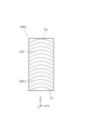
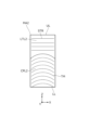
- the milling tool FT may be rotated and moved in the X direction with respect to the molded product MA, thereby forming a tool mark TM having a trajectory as shown in FIG. 8A.
- the milling tool FT having a small-diameter cutting edge may be rotated and reciprocated in the Z direction with respect to the molded product MA, so that even the small-sized milling tool FR can form the first surface portion PL1 with a large area.
- a plurality of rows (here, two rows) of tool marks TM are formed, for example, as shown in FIG. 8B.
- a material such as an aluminum alloy material is extruded to form a long object, and then the long object is cut in parallel at predetermined intervals to produce a molded article MA1 as shown in FIGS. 9A and 9B.
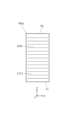
- the left side surface LTL1 of the molded product MA1 is a single plane except for the joint between the upper surface UL and the lower surface LL.
- the right side surface RTL of molded article MA1 has the same shape as the embodiment described above.
- a pull mark STR is formed over the entire left side surface LTL1.
- a cut surface CPL1 can be formed as shown in FIGS. 10A and 10B.
- flatness and sufficient dimensional accuracy as a surface to which the housing 182 of the solenoid valve unit 100 is attached can be ensured in the cut surface CPL1 extending over the entire left side surface LTL1.
- the amount of material cut and discarded by milling increases, and the machining time also increases, resulting in increased manufacturing costs.
- the range where the housing 182 of the solenoid valve unit 100 is attached is a part of the left side LTL1, there is no need to mill the entire left side LTL1.
- 11A and 11B show a molded product MA2 in which milling was performed only on the lower part of the left side LTL2 to form a cut surface CPL2, as another comparative example of the extruded molded product shown in FIGS. 9A and 9B.
- Molded product MA2 has the advantage that the amount of material that is cut out and discarded by milling is reduced, and the processing time is also shortened.
- a step STP is formed between the milled cut surface CPL2 and the unmilled left side surface LTL2, and burrs are generated on the upper edge EG of the step STP, which requires a process to remove. The problem is that it takes time.
- the unprocessed first surface part PL11 is A second surface portion PL2 (which exists in the direction (+Y direction) close to the center of the molded article MA) is formed. Therefore, even if part of the unprocessed first surface portion PL11 and second surface portion PL2 are removed by milling, the remainder of the second surface portion PL2 is not removed, reducing the amount of material that is cut and discarded. Since processing time is also shortened, manufacturing costs can be reduced. Further, the occurrence of burrs between the first surface portion PL1 and the second surface portion PL2 is suppressed. That is, manufacturing costs can be reduced without increasing the number of steps.
- the first surface portion PL1 and the third surface portion PL3 can be held between the chuck CK during machining in a later process. , thereby improving manufacturing efficiency.
- the housing 182 and the attractor 140 can be brought into close contact, and a good magnetic field can be maintained during the operation of the solenoid valve unit 100. A path is formed.
- the shape of the molded product of the valve body is not necessarily limited to the shape of the above-described embodiment.
- the second surface portion PL2 is formed on a surface located on the inner side of the valve body 2 than the first surface portion PL1 in the normal direction of the first surface portion PL1.
- the second surface portion PL2 may be formed on a plane that is located at the same position as the first surface portion PL1 in the normal direction of the first surface portion PL1, or on a plane that is substantially the same as the first surface portion PL1.
- FIGS. 12A and 12B the first surface portion PL1 is shown by a two-dot chain line, and an example is shown in which the second surface portion PL2 is substantially the same plane as the first surface portion PL1.
- substantially the same plane is not limited to being a completely identical plane, but is a surface that allows the valve body 2 to be stably clamped across the first surface portion PL1 and the second surface portion PL2 when the valve body 2 is clamped by the chuck CK.
- the second surface portion PL2 may be, for example, a surface that is slightly lower than the first surface portion PL1 in the normal direction of the first surface portion PL1.
- the second surface portion PL2 may be a plane that is slightly inclined with respect to the first surface portion PL1.
- the second surface portion PL2 may be a curved surface.
- the second surface portion PL2 can also be used as the third surface portion described in relation to the first embodiment. That is, the second surface portion PL2 can be used as a surface to be chucked by the chuck CK.
- the pre-processing left side surface LTL3 of the molded product MA3 after extrusion molding may have a pre-processing first surface portion PL11, a second surface portion PL2, and a slope (a flat second surface) SL connecting the pre-processing first surface portion PL11 and the second surface portion PL2.
- the pre-processing first surface portion PL11 is formed on a surface shifted in a direction away from the center of the molded product MA (-Y direction) with respect to the second surface portion PL2.
- the pre-processing first surface portion PL11 is formed, for example, on a plane parallel to the second surface portion PL2.
- the right side surface RTL3 of the molded product MA3 is, for example, flat. Drawing lines are omitted from the illustration.
- the first surface portion PL1 is formed to be coplanar or approximately coplanar with the second surface portion PL2, as shown by the two-dot chain line.
- the second surface portion PL2 becomes an adjacent surface portion adjacent to the mounting surface (base surface portion).
- the first surface portion PL1 can be formed into a plane having sufficient dimensional accuracy as a surface on which the housing 182 of the electromagnetic valve unit 100 is attached.
- the amount of material to be cut and discarded is reduced, and the machining time is also shortened. Further, burr generation is suppressed between the first surface portion PL1 and the second surface portion PL2.
- a straight line which is a modified example of the recess D, is formed between the first surface portion PL11 before processing and the third surface portion PL3.
- a groove portion SGV may be formed.
- the unprocessed first surface portion PL11 is parallel to the third surface portion PL3, and is formed on a surface that is shifted in a direction (-Y direction) away from the center of the molded product MA with respect to the third surface portion PL1.
- the unprocessed first surface portion PL11 is formed, for example, in a plane parallel to the third surface portion PL3.
- the right side surface RTL4 of the molded product MA4 has a planar shape. Drawing lines are omitted from illustration.
- a first surface portion PL1 that is flush with the third surface portion PL1 is formed, as shown by the dotted line.
- the surface of the remaining straight groove portion SGV becomes an adjacent surface portion adjacent to the mounting surface (base surface portion).
- the first surface portion PL1 can be formed into a plane having sufficient dimensional accuracy as a surface to which the housing 182 of the solenoid valve unit 100 is attached.
- the amount of material to be cut and discarded is reduced, and the machining time is also shortened. Further, the occurrence of burrs between the first surface portion PL1 and the straight groove portion SGV can be suppressed.
- the recess D or the linear groove SG having the second surface portion PL2 is formed linearly has been described, but the recess D or the linear groove portion having the second surface portion PL2 is The shape of the straight groove portion SG is set according to the first surface portion PL1.
- the recessed portion may be formed in a curved shape in a plan view, or may be formed in a shape in which a plurality of linear portions are connected in a plan view.
- the recessed portion having the second surface portion PL2 is connected to a pair of opposing edges of the left side surface LTL of the valve body 2, but other In the example, the recess having the second surface portion PL2 may be connected to two adjacent edges of the side surface of the valve body 2.
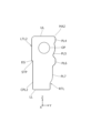
- the molded article MA5 according to the fourth embodiment shown in FIGS. 14A, 14B, and 14C can be formed, for example, by forging. More specifically, the left side surface LTL5 of the molded product MA5 has a third surface portion PL3 having an L-shaped plane and a rectangular first surface portion PL11 before processing. An L-shaped groove portion LGV is formed between the surface portion PL3 and the L-shaped groove portion LGV, which is bent at right angles and extends in two directions (X direction and Y direction).
- the first surface portion PL1 is parallel to the third surface portion PL3, and is formed on a surface that shifts with respect to the third surface portion PL1 in a direction away from the center of the molded article MA ( ⁇ Y direction).
- the unprocessed first surface portion PL11 is formed, for example, in a plane parallel to the third surface portion PL3.
- the molded product MA5 is not limited to forging, and may be formed by processing using a die, such as casting or die casting. Drawing lines are omitted from illustration.
- a first surface portion PL1 that is flush with the third surface portion PL1 is formed as shown by the dotted line.
- the surface of the remaining L-shaped groove portion LGV becomes an adjacent surface portion adjacent to the mounting surface (base surface portion).
- the first surface portion PL1 can be formed into a flat surface having sufficient dimensional accuracy as a surface to which the housing 182 of the solenoid valve unit 100 is attached. Furthermore, compared to the case where the entire left side LTL 5 is milled, the amount of material that is cut and discarded is reduced, and the machining time is also shortened. Furthermore, the occurrence of burrs between the first surface portion PL1 and the L-shaped groove portion LGV can be suppressed.
- valve body 2 has the first surface portion PL1, the second surface portion PL2, and the third surface portion PL3.
- the valve body 2 has the first surface portion PL1 and the second surface portion PL2, but does not have the third surface portion PL3, and the second surface portion PL2 has the second surface portion PL2 in the normal direction of the first surface portion PL1.
- An example has been described in which it is formed on a plane that is at the same position as the first surface portion PL1 or on a plane that is substantially the same.
- the left side surface LTL has a first surface portion PL1 and a second surface portion PL2, and the second surface portion PL2 is aligned with the valve body relative to the first surface portion PL1 along the normal direction of the first surface portion PL1.
- 2 is formed on a surface that slopes inwardly.
- the method of forming the second surface portion PL2 is not limited.
- the second surface portion PL2 may be formed by extrusion molding, for example.
- the recessed portion having the second surface portion PL2 may be formed in an annular shape, and the first surface portion PL1 may be surrounded by the recessed portion.
- the annular shape of the recessed portion having the second surface portion PL2 is not limited, and may be a circular annular shape or a rectangular annular shape.
- High-pressure refrigerant is supplied to the expansion valve unit 1 from the condenser 102. More specifically, the high-pressure refrigerant from the condenser 102 is supplied to the first flow path 21 .
- the solenoid valve unit 100 is in an open state. In this case, the refrigerant supplied to the first flow path 21 reaches the valve chamber VS via the high pressure side flow path 112, the circular opening 114, and the low pressure side flow path 113.
- the valve body 3 When the valve body 3 is seated on the valve seat 20, the first flow path 21 on the upstream side of the valve chamber VS and the second flow path 22 on the downstream side of the valve chamber VS are in a non-communicating state. On the other hand, when the valve body 3 is spaced apart from the valve seat 20, the refrigerant supplied to the valve chamber VS passes through the operating rod insertion hole 27 and the second flow path 22 and is sent to the evaporator. Note that switching between the closed state and the open state of the expansion valve unit 1 is performed by an actuation rod 5 connected to the power element 8.
- the power element 8 is provided with a pressure working chamber PA and a lower space LS partitioned by a diaphragm 83. Therefore, when the working gas in the pressure working chamber PA is liquefied, the working rod 5 moves toward the diaphragm, and when the liquefied working gas is vaporized, the working rod 5 moves toward the valve body. In this way, the expansion valve unit 1 is switched between the open state and the closed state.
- the lower space LS of the power element 8 is connected to the return flow path 23. Therefore, the phase (gas phase, liquid phase, etc.) of the working gas in the pressure actuated chamber PA changes depending on the temperature and pressure of the refrigerant flowing through the return flow path 23, and the actuating rod 5 is driven.
- the amount of refrigerant supplied from the expansion valve unit 1 to the evaporator is automatically adjusted depending on the temperature and pressure of the refrigerant returning from the evaporator to the expansion valve unit 1.
- the solenoid valve unit 100 when the solenoid valve unit 100 is in the closed state, the refrigerant supplied to the first flow path 21 is disconnected from the circular opening 114 and the low pressure side flow path 113, so that the refrigerant is supplied to the first flow path 21.
- the valve chamber VS is not supplied from the passage 21, and its flow is blocked.
- the pressure in the plunger side space of the main valve body 170 which communicates with the high-pressure side flow path 112 via the pressure equalization passage 172, is greater than the internal pressure of the cylindrical portion 113a which communicates with the low-pressure side flow path 113, so that the main valve body 170 remains seated on the end of the cylindrical portion 113a against the spring force, i.e., the solenoid valve unit 100 is in a closed state, and the flow of refrigerant from the high-pressure side flow path 112 to the low-pressure side flow path 113 is blocked.
- the main valve body 170 is separated from the valve body 2 according to the urging force of the spring 173, and a gap is created between the main valve body 170 and the end of the cylindrical part 113a, and the flow from the high pressure side flow path 112 to the low pressure side flow through this gap. Fluid flows into channel 113.
- the third surface P portion L3 does not necessarily have to be a flat surface, and may be a curved surface as long as it can contact the chuck CK together with the first surface portion PL1 and support the chuck CK.
- the first surface portion PL1 may be a surface that has been subjected to not only milling processing but also other cutting processing.
- an expansion valve with a solenoid valve having the solenoid valve unit 100 has been described, but as another example of the valve device of the present invention, it is a valve device having an electric valve as a fixed object. Good too.
- the object to be fixed to the valve body is not limited to the electromagnetic valve unit 100, but may be other parts or other devices included in the valve device.
- the object to be fixed may be a component or device other than the structure of the valve device.
- the object to be fixed may be another device installed near the location where the valve device is installed.
- the second surface portion PL2 and the third surface portion PL3 of the left side surface LTL are formed by extrusion molding.
- the second surface portion PL2 and the third surface portion PL3 may be formed by extrusion molding and then subjected to processing such as polishing or cutting.
- the upper surface UL, the lower surface LL, the right side RTL, the front surface FTL, and the back surface BTL may be formed by extrusion molding and then subjected to polishing or cutting.
- the second surface portion PL2 of the valve body 2 is located at the same position as the first surface portion PL1 in the normal direction of the first surface portion PL1, or
- the valve body 2 is formed on a surface located on the inner side of the valve body 2.
- the second surface portion PL2 was formed on a surface that does not protrude relative to the first surface portion PL1 in the normal direction of the first surface portion PL1.
- the second surface portion PL2 is not limited to being formed in a shape in which the entire area does not protrude with respect to the first surface portion PL1.
- the adjacent portion adjacent to at least a part of the edge of the first surface portion PL1 does not protrude with respect to the first surface portion PL1 in the normal direction of the first surface portion PL1 (that is, the adjacent portion is located at the same position as the first surface portion PL1, or Any shape may be used as long as it is located on the inner side of the valve body 2 than the surface portion PL1.
- the second surface portion PL2 is an example of a surface including an adjacent portion.
- This adjacent portion is formed by cutting the pre-machined first surface portion PL11 of the molded products MA, MA3, MA4, and MA5 to form the first surface portion PL1, and is formed based on a pre-machined adjacent portion (adjacent portion) adjacent to at least a portion of the edge of the pre-machined first surface portion PL11.
- the pre-machined adjacent portion may have a shape that can prevent interference with a tool and suppress the occurrence of burrs when cutting the pre-machined first surface portion PL11.
- the pre-machined adjacent portion adjacent to at least a portion of the edge of the pre-machined first surface portion PL11 is formed in a shape that is lower than the pre-machined first surface portion PL11, and this pre-machined adjacent portion may suppress interference of the cutting tool with the portion of the pre-machined left side surface LTL1 other than the pre-machined first surface portion PL11.
- the pre-machined adjacent portion of the pre-machined first surface portion PL11 has the shape described above, when the pre-machined first surface portion PL11 is cut to form the first surface portion PL1, the adjacent portion adjacent to at least a portion of the edge of the first surface portion PL1 has a shape that does not protrude relative to the first surface portion PL1 in the normal direction of the first surface portion PL1.
- the unprocessed first surface part PL11 has a shape that protrudes from the unprocessed adjacent part adjacent to at least a part of the edge of the unprocessed first surface part PL11 on the unprocessed left side surface LTL1 of the molded product.
- the adjacent portion before machining may function as a relief portion for the cutting tool to escape. Escape means that the cutting tool does not interfere.
- the second surface portion PL2 may have a shape in which, for example, a portion opposite to the first surface portion PL1 protrudes beyond the first surface portion PL1 in the normal direction of the first surface portion PL1.
- the second surface portion PL2 is formed on a surface located inward from the first surface portion PL1 in the normal direction of the first surface portion PL1.
- the portion may be located at the same position as the first surface portion PL1 in the normal direction of the first surface portion PL1.
- a portion of the second surface portion PL2 has a shape that follows the return flow path 23, and is formed into a curved surface that projects outward.
- the top of the second surface portion PL2 may be located at the same position as the first surface portion PL1 in the normal direction of the first surface portion PL1.
- the unprocessed first surface portion PL11 was subjected to milling as an example of cutting.
- the cutting process is not limited to milling process, and may be a cutting process other than milling process.
- the first surface portion PL1 was formed by cutting the molded products MA, MA3, MA4, and MA5, but instead of or in addition to the cutting, the first surface portion PL1 was formed by cutting the molded products MA, MA3, MA4, and MA5.
- the first surface portion PL1 may be formed by applying the same method.
- Expansion valve unit 2 Valve body 3: Valve body 4: Biasing device 5: Operating rod 6: Operating rod vibration isolation spring 8: Power element 20: Valve seat 21: First flow path 22: Second flow path 23 : Return flow path 26 : Annular part 27 : Operating rod insertion hole 41 : Coil spring 100 : Solenoid valve unit 140 : Attractor 150 : Plunger 160 : Pilot valve body 170 : Main valve body 180 : Coil unit 181 : Solenoid coil 182 : Housing ESV: Expansion valve with solenoid valve MA, MA3, MA4, MA5: Molded product
Landscapes
- Engineering & Computer Science (AREA)
- General Engineering & Computer Science (AREA)
- Mechanical Engineering (AREA)
- Physics & Mathematics (AREA)
- Electromagnetism (AREA)
- Magnetically Actuated Valves (AREA)
- Valve Housings (AREA)
Abstract
Description
弁本体を有する弁装置において、
前記弁本体の一側面は、所定の切削加工または研削加工が施されて形成された、被固定物を取り付け可能な平面である基礎面部と、前記基礎面部の縁の少なくとも一部に隣接する隣接部とを備え、
前記隣接部は、前記所定の切削加工または研削加工が施されておらず、前記基礎面部の法線方向において前記基礎面部に対して突出しない形状を有する、
ことを特徴とする。
弁本体を有する弁装置において、
前記弁本体の一側面が、被固定物を取り付け可能な平面である基礎面部と、前記基礎面部に隣接する隣接面部とを有し、
前記隣接面部は、前記基礎面部の法線方向において前記基礎面部と同位置か、または前記基礎面部よりも前記弁本体の内方側に位置し、
前記基礎面部の平均面粗さは、前記隣接面部の平均面粗さと異なっている、
ことを特徴とする。
本発明の膨張弁は、
弁室、前記弁室の上面に形成されるオリフィス、前記弁室及び外部に連通し、前記弁室に冷媒を供給する供給側流路、前記オリフィス及び外部に連通し、前記オリフィスからの前記冷媒を外部に排出する排出側流路、及び前記排出側流路から排出された冷媒を流す戻り流路を有する弁本体と、
前記弁室に配置される弁体と、
前記弁本体の上面に設けられ、前記弁体を駆動する駆動力を生じるパワーエレメントと、
前記パワーエレメントの駆動力を前記弁体に伝達する作動棒と、
前記弁本体の一方の側面に取り付けられる被固定物と、
を備え、
前記供給側流路は、前記弁本体の前面から前記弁室まで延び、
前記排出側流路は、前記弁本体の背面から前記オリフィスまで延び、
前記戻り流路は、前記前面から前記背面まで延び、
前記供給側流路に対して前記排出側流路が上方に位置し、
前記排出側流路に対して前記戻り流路が上方に位置し、
前記側面は、前記戻り流路に沿って形成される凹部、及び前記側面の下端側から前記凹部までにわたって所定の切削加工または研削加工が施されることで形成された、前記被固定物を取り付け可能な平面である基礎面部を備える、ことを特徴とする。
素材から弁本体の中間加工品を形成する第1の工程であって、前記中間加工品の一側面は、加工前基礎面部と、前記加工前基礎面部の縁の少なくとも一部に隣接する隣接部とを有し、前記加工前基礎面部が前記隣接部に対して突出した形状を有する、第1の工程と、
前記加工前基礎面部に切削加工または研削加工を施して被固定物を固定可能な平面である基礎面部を形成する第2の工程と、を有する、
ことを特徴とする。
本発明の膨張弁の製造方法は、
弁室、前記弁室の上面に形成されるオリフィス、前記弁室及び外部に連通し、前記弁室に冷媒を供給する供給側流路、前記オリフィス及び外部に連通し、前記オリフィスからの前記冷媒を外部に排出する排出側流路、及び前記排出側流路から排出された冷媒を流す戻り流路を有する弁本体と、
前記弁室に配置される弁体と、
前記弁本体の上面に設けられ、前記弁体を駆動する駆動力を生じるパワーエレメントと、
前記パワーエレメントの駆動力を前記弁体に伝達する作動棒と、
前記弁本体の一方の側面に取り付けられる被固定物と、
を備え、
前記供給側流路は、前記弁本体の前面から前記弁室まで延び、
前記排出側流路は、前記弁本体の背面から前記オリフィスまで延び、
前記戻り流路は、前記前面から前記背面まで延び、
前記供給側流路に対して前記排出側流路が上方に位置し、
前記排出側流路に対して前記戻り流路が上方に位置する膨張弁の製造方法であって、
素材から前記弁本体の中間加工品を形成する第1の工程であって、前記中間加工品の一側面は、加工前基礎面部と、前記加工前基礎面部の縁の少なくとも一部に隣接する隣接部とを有し、前記加工前基礎面部が前記隣接部に対して突出した形状を有する、第1の工程と、
前記加工前基礎面部に切削加工または研削加工を施して前記被固定物を固定可能な平面である基礎面部を形成する第2の工程と、を有する、
ことを特徴とする。
以下、図面を参照して本発明の弁装置の一タイプである電磁弁付き膨張弁の第1の実施形態について説明する。電磁弁付き膨張弁ESVは、膨張弁ユニット1と電磁弁ユニット100とからなるが、膨張弁ユニット1と電磁弁ユニット100とは弁本体2を共通に用いる。本実施形態では、一例として、弁本体2に対するパワーエレメント8側を上側として上下方向を設定し、上下方向に直交する方向のうち、弁本体2及び電磁弁ユニット100が並ぶ方向を幅方向として設定し、上下方向及び幅方向の双方に直交する方向を前後方向として設定する。
まず、図1を参照して、本実施形態の膨張弁ユニット1の構造を説明する。
図1は、本実施形態における電磁弁付き膨張弁ESVを模式的に示す概略断面図である。電磁弁付き膨張弁ESVにおける膨張弁ユニット1の構造について説明する。弁本体2の軸線をLとする。ここで、軸線Lとは作動棒5の中心線をいい、すなわち上下方向に平行であり、後述する弁室VSの中心を通る線である。
次に、図2、3を参照して、本実施形態の電磁弁ユニット(単に電磁弁ともいう)100の構造を説明する。電磁弁ユニット100は、弁本体2に固定される被固定物の一例である。
図2は、図1に対し軸線L回りに90度だけ位相を変えた断面における電磁弁付き膨張弁ESVの縦断面図である。図3は、図2の構成をA-A線に沿って切断して底面視した図であるが、コイルばね41、弁体サポート42、弁体3、及び作動棒5は省略して図示する。電磁弁ユニット100の軸線をOとする。
弁本体2の製造工程について説明する。
図4A~7は、弁本体2の製造工程を説明する模式図である。製造工程は、第1の工程、第2の工程、及び第3の工程を有している。
第1の工程は、弁体3の中間加工品である成形品MAを形成する工程である。
まず、素材例えばアルミニウム合金材料を押出成形して長尺物を成形したのち、所定間隔で平行に長尺物を切断することにより、図4A、4Bに示すような成形品MAを形成する。成形品MAは、成形方向に沿って形成される開口OP(戻り流路23に対応)を有していてもよい。
第2の工程は、加工前左側面LTL1の加工前第1面部PL11に切削加工を施して、電磁弁ユニット100を固定可能な第1面部PL1を形成する工程である。
より具体的には、図5Aに示すように、加工前左側面LTL1が露出するように、成形品MAを固定し、回転するフライス工具FTを下面LL側から+Z方向に向かって成形品MAに接近させる。このとき、切れ刃の下端はZX面内で回転するものとする。なお、成形品MAは、例えば、前面FLと背面BTLをチャックCKで挟持して固定される。成形品MAの固定は、チャックに限定されるものではない。他の例では、成形品MAは、接着剤で固定されてもよい。
第3の工程は、成形品MAに、第1の工程及び第2の工程で施された加工以外の加工を施すことで、成形品MAから弁本体2を形成する工程である。
チャックCKから成形品MAを離脱させたのち、後工程で加工する面が露出するように、新たに成形品MAを固定し直す。より具体的には、図7に示すように、一方のチャックCK1の平坦面を、第1面部PL1と第3面部PL3に当接させ、他方のチャックCK2の平坦面を、第4面部PL4と第6面部PL6に当接させる。第1面部PL1と第3面部PL3とは共通の仮想平面内に存在し、また第4面部PL4と第6面部PL6も共通の仮想平面内に存在し、さらに両仮想平面は平行であるため、チャックCK1、CK2により安定して成形品MAを固定できる。
比較例にかかる弁本体の成形品MA1、MA2の製造工程について説明する。
図9A~11Bは、成形品MA1、MA2の製造工程を説明する模式図であるが、XYZ方向は上述した実施形態で用いたものと共通とする。
弁本体の成形品の形状は、必ずしも上述の実施の形態の形状に限られない。第1の実施形態においては、第2面部PL2が、第1面部PL1の法線方向において第1面部PL1よりも弁本体2の内方側に位置する面に形成される例を説明したが、例えば、第2面部PL2は、第1面部PL1の法線方向において第1面部PL1と同位置となる平面または略同一となる平面に形成されてもよい。この例を、図12A、12Bを用いて説明する。なお、図12Bにおいて、第1面部PL1を2点鎖線で示しており、第2面部PL2が第1面部PL1に対して略同一な平面である例を示している。
また、第1の実施形態においては、成形品MAを押出成形で形成し、凹部Dを押出成形で形成する例を説明したが、凹部Dは、成形品MAに対して切削加工を施すことで形成されてもよい。この例を、図13A、13Bを用いて説明する。
また、第1の実施形態及び第3の実施形態においては、第2面部PL2を有する凹部Dまたは直線溝部SGが直線状に形成される例を説明したが、第2面部PL2を有する凹部Dまたは直線溝部SGの形状は、第1面部PL1に応じて設定される。例えば凹部は、平面視で曲線状に形成されてもよく、または、平面視で複数の直線部が連なった形状に形成されてもよい。さらに、第1の実施形態及び第3の実施形態においては、第2面部PL2を有する凹部が、弁本体2の左側面LTLの対向する一対の縁に接続される例を説明したが、他の例では、第2面部PL2を有する凹部は、弁本体2の側面の隣接する二つの縁に接続されてもよい。
第1の実施形態、第3の実施形態、及び第4の実施形態においては、弁本体2が、第1面部PL1、第2面部PL2、及び第3面部PL3を有する例が説明された。そして、第2の実施形態では、弁本体2が第1面部PL1及び第2面部PL2を有して第3面部PL3を有さず、第2面部PL2が第1面部PL1の法線方向において第1面部PL1と同位置となる平面または略同一となる平面に形成された例が説明された。他の例では、図15に示す第5の実施形態のように、弁本体2は第1面部PL1及び第2面部PL2を有して第3面部PL3を有さず、第2面部PL2が第1面部PL1の法線方向において第1面部PL1に対して弁本体2の内方側に位置する面であってもよい。この例としては、左側面LTLは、第1面部PL1及び第2面部PL2を有し、第2面部PL2は、第1面部PL1の法線方向に沿って、第1面部PL1に対して弁本体2の内方側に傾斜する面に形成される。第2面部PL2を形成する方法は限定されない。第2面部PL2は、例えば、押出成形で形成されてもよい。
図1を参照して、電磁弁付き膨張弁ESVが冷凍サイクルに組み込まれた際の動作例について説明する。コンプレッサで加圧された冷媒は、冷凍サイクルのコンデンサで液化され、膨張弁ユニット1に送られる。また、膨張弁ユニット1で断熱膨張された冷媒は冷凍サイクルのエバポレータに送り出され、エバポレータの周囲を流れる空気と熱交換される。エバポレータから戻る冷媒は、膨張弁ユニット1(より具体的には、戻り流路23)を通ってコンプレッサ側へ戻される。このとき、エバポレータを通過することで、第2流路22内の流体圧は、戻り流路23の流体圧より大きくなる。
次に、電磁弁ユニット100の開閉弁動作について説明する。図2、3において、不図示の電源から電磁コイル181に給電されたとき、電磁コイル181が発生した磁界により、プランジャ150、吸引子140、およびハウジング182を通る磁路が生じ、中間スプリング152の付勢力に抗してプランジャ150を、弁本体2側に押圧する磁力が生じる。プランジャ150が押圧されると、パイロット弁体160が同方向に移動し、主弁体170のパイロット弁口171を塞ぐとともに、主弁体170を押し下げて円筒部113aの端部(主弁座113b)を遮蔽する。かかる状態では、均圧通路172を介して高圧側流路112に連通する主弁体170のプランジャ側空間の圧力が、低圧側流路113に連通する円筒部113aの内圧より大きいため、スプリングの付勢力に抗して主弁体170が円筒部113aの端部に着座した状態が維持され、すなわち電磁弁ユニット100が閉弁状態となり、高圧側流路112から低圧側流路113への冷媒の流れが遮断される。
2 :弁本体
3 :弁体
4 :付勢装置
5 :作動棒
6 :作動棒防振ばね
8 :パワーエレメント
20 :弁座
21 :第1流路
22 :第2流路
23 :戻り流路
26 :環状部
27 :作動棒挿通孔
41 :コイルばね
100 :電磁弁ユニット
140 :吸引子
150 :プランジャ
160 :パイロット弁体
170 :主弁体
180 :コイルユニット
181 :電磁コイル
182 :ハウジング
ESV :電磁弁付き膨張弁
MA、MA3、MA4、MA5 :成形品
Claims (12)
- 弁本体を有する弁装置において、
前記弁本体の一側面は、所定の切削加工または研削加工が施されて形成された、被固定物を取り付け可能な平面である基礎面部と、前記基礎面部の縁の少なくとも一部に隣接する隣接部とを備え、
前記隣接部は、前記所定の切削加工または研削加工が施されておらず、前記基礎面部の法線方向において前記基礎面部に対して突出しない形状を有する、
ことを特徴とする弁装置。 - 前記基礎面部にはツールマークが形成され、前記隣接部には押出成形による引き目が形成されている、
ことを特徴とする請求項1に記載の弁装置。 - 前記一側面は、前記基礎面部と同一平面、または略同一な平面に形成される別の平面部を有し、前記隣接部は、前記基礎面部と前記別の平面部との間に位置する凹部である、
ことを特徴とする請求項1に記載の弁装置。 - 前記弁装置は、前記被固定物として電磁弁を備える、
ことを特徴とする請求項1~3のいずれか一項に記載の弁装置。 - 弁本体を有する弁装置において、
前記弁本体の一側面が、被固定物を取り付け可能な平面である基礎面部と、前記基礎面部に隣接する隣接面部とを有し、
前記隣接面部は、前記基礎面部の法線方向において前記基礎面部と同位置か、または前記基礎面部よりも前記弁本体の内方側に位置し、
前記基礎面部の平均面粗さは、前記隣接面部の平均面粗さと異なっている、
ことを特徴とする弁装置。 - 前記基礎面部は切削加工または研削加工が施された面である、
ことを特徴とする請求項5に記載の弁装置。 - 弁室、前記弁室の上面に形成されるオリフィス、前記弁室及び外部に連通し、前記弁室に冷媒を供給する供給側流路、前記オリフィス及び外部に連通し、前記オリフィスからの前記冷媒を外部に排出する排出側流路、及び前記排出側流路から排出された冷媒を流す戻り流路を有する弁本体と、
前記弁室に配置される弁体と、
前記弁本体の上面に設けられ、前記弁体を駆動する駆動力を生じるパワーエレメントと、
前記パワーエレメントの駆動力を前記弁体に伝達する作動棒と、
前記弁本体の一方の側面に取り付けられる被固定物と、
を備え、
前記供給側流路は、前記弁本体の前面から前記弁室まで延び、
前記排出側流路は、前記弁本体の背面から前記オリフィスまで延び、
前記戻り流路は、前記前面から前記背面まで延び、
前記供給側流路に対して前記排出側流路が上方に位置し、
前記排出側流路に対して前記戻り流路が上方に位置し、
前記側面は、前記戻り流路に沿って形成される凹部、及び前記側面の下端側から前記凹部までにわたって所定の切削加工または研削加工が施されることで形成された、前記被固定物を取り付け可能な平面である基礎面部を備える、
ことを特徴とする膨張弁。 - 素材から弁本体の中間加工品を形成する第1の工程であって、前記中間加工品の一側面は、加工前基礎面部と、前記加工前基礎面部の縁の少なくとも一部に隣接する隣接部とを有し、前記加工前基礎面部が前記隣接部に対して突出した形状を有する、第1の工程と、
前記加工前基礎面部に切削加工または研削加工を施して被固定物を固定可能な平面である基礎面部を形成する第2の工程と、を有する、
ことを特徴とする弁装置の製造方法。 - 前記第2の工程において、前記加工前基礎面部にフライス加工を施すことにより前記基礎面部を形成する、
ことを特徴とする請求項8に記載の弁装置の製造方法。 - 前記第1の工程において、前記隣接部を挟んで前記加工前基礎面部と対向し、前記基礎面部と同一平面または略同一となる別の平面部を形成する、
ことを特徴とする請求項8に記載の弁装置の製造方法。 - 前記第1の工程において、前記加工前基礎面部、前記隣接部、及び前記別の平面部を押出成形で形成する、
ことを特徴とする請求項10に記載の弁装置の製造方法。 - 弁室、前記弁室の上面に形成されるオリフィス、前記弁室及び外部に連通し、前記弁室に冷媒を供給する供給側流路、前記オリフィス及び外部に連通し、前記オリフィスからの前記冷媒を外部に排出する排出側流路、及び前記排出側流路から排出された冷媒を流す戻り流路を有する弁本体と、
前記弁室に配置される弁体と、
前記弁本体の上面に設けられ、前記弁体を駆動する駆動力を生じるパワーエレメントと、
前記パワーエレメントの駆動力を前記弁体に伝達する作動棒と、
前記弁本体の一方の側面に取り付けられる被固定物と、
を備え、
前記供給側流路は、前記弁本体の前面から前記弁室まで延び、
前記排出側流路は、前記弁本体の背面から前記オリフィスまで延び、
前記戻り流路は、前記前面から前記背面まで延び、
前記供給側流路に対して前記排出側流路が上方に位置し、
前記排出側流路に対して前記戻り流路が上方に位置する膨張弁の製造方法であって、
素材から前記弁本体の中間加工品を形成する第1の工程であって、前記中間加工品の一側面は、加工前基礎面部と、前記加工前基礎面部の縁の少なくとも一部に隣接する隣接部とを有し、前記加工前基礎面部が前記隣接部に対して突出した形状を有する、第1の工程と、
前記加工前基礎面部に切削加工または研削加工を施して前記被固定物を固定可能な平面である基礎面部を形成する第2の工程と、を有する、
ことを特徴とする膨張弁の製造方法。
Priority Applications (3)
| Application Number | Priority Date | Filing Date | Title |
|---|---|---|---|
| CN202380051291.4A CN119836535A (zh) | 2022-09-22 | 2023-09-21 | 阀装置、膨胀阀、阀装置的制造方法及膨胀阀的制造方法 |
| JP2024548319A JPWO2024063145A1 (ja) | 2022-09-22 | 2023-09-21 | |
| DE112023003953.4T DE112023003953T5 (de) | 2022-09-22 | 2023-09-21 | Ventilvorrichtung, Entspannungsventil, Verfahren zur Herstellung einer Ventilvorrichtung und ein Verfahren zur Feststellung eines Entspannungsventils |
Applications Claiming Priority (2)
| Application Number | Priority Date | Filing Date | Title |
|---|---|---|---|
| JP2022151066 | 2022-09-22 | ||
| JP2022-151066 | 2022-09-22 |
Publications (1)
| Publication Number | Publication Date |
|---|---|
| WO2024063145A1 true WO2024063145A1 (ja) | 2024-03-28 |
Family
ID=90454770
Family Applications (1)
| Application Number | Title | Priority Date | Filing Date |
|---|---|---|---|
| PCT/JP2023/034327 Ceased WO2024063145A1 (ja) | 2022-09-22 | 2023-09-21 | 弁装置、膨張弁、弁装置の製造方法、及び膨張弁の製造方法 |
Country Status (4)
| Country | Link |
|---|---|
| JP (1) | JPWO2024063145A1 (ja) |
| CN (1) | CN119836535A (ja) |
| DE (1) | DE112023003953T5 (ja) |
| WO (1) | WO2024063145A1 (ja) |
Citations (4)
| Publication number | Priority date | Publication date | Assignee | Title |
|---|---|---|---|---|
| JPH0522803U (ja) * | 1991-09-06 | 1993-03-26 | 株式会社トキメツク | マニホールドブロツク |
| JPH11182982A (ja) * | 1997-12-18 | 1999-07-06 | Fujikoki Corp | 膨張弁 |
| JP2003202691A (ja) * | 2002-01-09 | 2003-07-18 | Canon Inc | 電子写真感光体、該電子写真感光体の製造方法、及び該電子写真感光体を有するプロセスカートリッジ及び電子写真装置 |
| JP2014151691A (ja) * | 2013-02-06 | 2014-08-25 | Daido Steel Co Ltd | アクスルハウジングおよびアクスルハウジング製造装置 |
-
2023
- 2023-09-21 DE DE112023003953.4T patent/DE112023003953T5/de active Pending
- 2023-09-21 WO PCT/JP2023/034327 patent/WO2024063145A1/ja not_active Ceased
- 2023-09-21 CN CN202380051291.4A patent/CN119836535A/zh active Pending
- 2023-09-21 JP JP2024548319A patent/JPWO2024063145A1/ja active Pending
Patent Citations (4)
| Publication number | Priority date | Publication date | Assignee | Title |
|---|---|---|---|---|
| JPH0522803U (ja) * | 1991-09-06 | 1993-03-26 | 株式会社トキメツク | マニホールドブロツク |
| JPH11182982A (ja) * | 1997-12-18 | 1999-07-06 | Fujikoki Corp | 膨張弁 |
| JP2003202691A (ja) * | 2002-01-09 | 2003-07-18 | Canon Inc | 電子写真感光体、該電子写真感光体の製造方法、及び該電子写真感光体を有するプロセスカートリッジ及び電子写真装置 |
| JP2014151691A (ja) * | 2013-02-06 | 2014-08-25 | Daido Steel Co Ltd | アクスルハウジングおよびアクスルハウジング製造装置 |
Also Published As
| Publication number | Publication date |
|---|---|
| DE112023003953T5 (de) | 2025-08-07 |
| JPWO2024063145A1 (ja) | 2024-03-28 |
| CN119836535A (zh) | 2025-04-15 |
Similar Documents
| Publication | Publication Date | Title |
|---|---|---|
| CN111417780B (zh) | 容量控制阀及容量控制阀的控制方法 | |
| EP2055934B1 (en) | High-pressure fuel supply pump | |
| EP2482010B1 (en) | Expansion valve | |
| CN101737545B (zh) | 一种电磁阀及其加工方法 | |
| JP2005090794A (ja) | 冷却板の製造方法 | |
| JP2021156393A (ja) | パイロット式電磁弁 | |
| CN114667424B (zh) | 动力元件以及使用了该动力元件的膨胀阀 | |
| WO2024063145A1 (ja) | 弁装置、膨張弁、弁装置の製造方法、及び膨張弁の製造方法 | |
| CN105650318B (zh) | 膨胀阀 | |
| JP2023097936A (ja) | 電気的駆動弁 | |
| JP4565946B2 (ja) | バルブ駆動装置 | |
| KR20190107925A (ko) | 비례제어밸브 제조방법 및 이 제조방법에 의해 제조되는 비례제어밸브 | |
| CN114667423B (zh) | 动力元件以及使用了该动力元件的膨胀阀 | |
| CN114667422A (zh) | 动力元件以及使用了该动力元件的膨胀阀 | |
| CN1978961A (zh) | 阀装置 | |
| WO2020189092A1 (ja) | 膨張弁 | |
| JP2006132881A (ja) | 膨張弁 | |
| JP7373857B2 (ja) | パワーエレメント及びそれを用いた膨張弁 | |
| JPWO2019163879A1 (ja) | 減圧弁 | |
| JP7325083B2 (ja) | 膨張弁及びその製造方法 | |
| WO2020213420A1 (ja) | 電磁弁一体型膨張弁 | |
| JP7403168B2 (ja) | 膨張弁 | |
| JP2008181393A (ja) | 減圧弁 | |
| JP2023179868A (ja) | パイロット式電磁弁 | |
| JP2020143855A (ja) | 膨張弁 |
Legal Events
| Date | Code | Title | Description |
|---|---|---|---|
| 121 | Ep: the epo has been informed by wipo that ep was designated in this application |
Ref document number: 23868266 Country of ref document: EP Kind code of ref document: A1 |
|
| WWE | Wipo information: entry into national phase |
Ref document number: 2024548319 Country of ref document: JP |
|
| WWE | Wipo information: entry into national phase |
Ref document number: 202380051291.4 Country of ref document: CN |
|
| WWP | Wipo information: published in national office |
Ref document number: 202380051291.4 Country of ref document: CN |
|
| WWE | Wipo information: entry into national phase |
Ref document number: 112023003953 Country of ref document: DE |
|
| WWP | Wipo information: published in national office |
Ref document number: 112023003953 Country of ref document: DE |
|
| 122 | Ep: pct application non-entry in european phase |
Ref document number: 23868266 Country of ref document: EP Kind code of ref document: A1 |