WO2024062833A1 - Cellule d'analyse par fluorescence, dispositif d'analyse par fluorescence, procédé d'analyse par fluorescence et procédé de fabrication de cellule à soumettre à une analyse - Google Patents
Cellule d'analyse par fluorescence, dispositif d'analyse par fluorescence, procédé d'analyse par fluorescence et procédé de fabrication de cellule à soumettre à une analyse Download PDFInfo
- Publication number
- WO2024062833A1 WO2024062833A1 PCT/JP2023/030431 JP2023030431W WO2024062833A1 WO 2024062833 A1 WO2024062833 A1 WO 2024062833A1 JP 2023030431 W JP2023030431 W JP 2023030431W WO 2024062833 A1 WO2024062833 A1 WO 2024062833A1
- Authority
- WO
- WIPO (PCT)
- Prior art keywords
- fluorescence analysis
- fluorescence
- cell
- light
- analysis cell
- Prior art date
Links
- 238000012921 fluorescence analysis Methods 0.000 title claims abstract description 142
- 238000000034 method Methods 0.000 title claims description 12
- 238000004519 manufacturing process Methods 0.000 title claims description 8
- 238000004458 analytical method Methods 0.000 title description 8
- 239000007788 liquid Substances 0.000 claims abstract description 99
- 125000006850 spacer group Chemical group 0.000 claims abstract description 50
- 230000005284 excitation Effects 0.000 claims description 60
- 238000004364 calculation method Methods 0.000 claims description 18
- 238000002835 absorbance Methods 0.000 claims description 17
- 238000009434 installation Methods 0.000 claims description 17
- 238000001514 detection method Methods 0.000 claims description 15
- 238000012937 correction Methods 0.000 claims description 8
- 238000001917 fluorescence detection Methods 0.000 claims description 7
- VYPSYNLAJGMNEJ-UHFFFAOYSA-N Silicium dioxide Chemical compound O=[Si]=O VYPSYNLAJGMNEJ-UHFFFAOYSA-N 0.000 claims description 3
- 230000001678 irradiating effect Effects 0.000 claims description 2
- 238000009795 derivation Methods 0.000 claims 1
- 210000004027 cell Anatomy 0.000 description 140
- 230000009103 reabsorption Effects 0.000 description 21
- 238000005259 measurement Methods 0.000 description 19
- 239000000126 substance Substances 0.000 description 14
- 230000003287 optical effect Effects 0.000 description 9
- 230000000694 effects Effects 0.000 description 5
- 239000000463 material Substances 0.000 description 4
- 238000007865 diluting Methods 0.000 description 3
- 238000003825 pressing Methods 0.000 description 3
- 235000013361 beverage Nutrition 0.000 description 2
- 238000010790 dilution Methods 0.000 description 2
- 239000012895 dilution Substances 0.000 description 2
- 235000015203 fruit juice Nutrition 0.000 description 2
- 230000000704 physical effect Effects 0.000 description 2
- 239000004278 EU approved seasoning Substances 0.000 description 1
- XUIMIQQOPSSXEZ-UHFFFAOYSA-N Silicon Chemical compound [Si] XUIMIQQOPSSXEZ-UHFFFAOYSA-N 0.000 description 1
- 235000013405 beer Nutrition 0.000 description 1
- 239000003086 colorant Substances 0.000 description 1
- 238000005260 corrosion Methods 0.000 description 1
- 230000007797 corrosion Effects 0.000 description 1
- 238000010586 diagram Methods 0.000 description 1
- 239000003792 electrolyte Substances 0.000 description 1
- -1 etc.) Substances 0.000 description 1
- 235000013305 food Nutrition 0.000 description 1
- 235000011194 food seasoning agent Nutrition 0.000 description 1
- 235000013402 health food Nutrition 0.000 description 1
- 239000012535 impurity Substances 0.000 description 1
- 235000015110 jellies Nutrition 0.000 description 1
- 239000008274 jelly Substances 0.000 description 1
- 239000003921 oil Substances 0.000 description 1
- 230000002093 peripheral effect Effects 0.000 description 1
- 229910052710 silicon Inorganic materials 0.000 description 1
- 239000010703 silicon Substances 0.000 description 1
- 239000002904 solvent Substances 0.000 description 1
- 238000004611 spectroscopical analysis Methods 0.000 description 1
- 229910001220 stainless steel Inorganic materials 0.000 description 1
- 239000010935 stainless steel Substances 0.000 description 1
- 229910052724 xenon Inorganic materials 0.000 description 1
- FHNFHKCVQCLJFQ-UHFFFAOYSA-N xenon atom Chemical compound [Xe] FHNFHKCVQCLJFQ-UHFFFAOYSA-N 0.000 description 1
Images


Classifications
-
- G—PHYSICS
- G01—MEASURING; TESTING
- G01N—INVESTIGATING OR ANALYSING MATERIALS BY DETERMINING THEIR CHEMICAL OR PHYSICAL PROPERTIES
- G01N21/00—Investigating or analysing materials by the use of optical means, i.e. using sub-millimetre waves, infrared, visible or ultraviolet light
- G01N21/01—Arrangements or apparatus for facilitating the optical investigation
- G01N21/03—Cuvette constructions
- G01N21/05—Flow-through cuvettes
-
- G—PHYSICS
- G01—MEASURING; TESTING
- G01N—INVESTIGATING OR ANALYSING MATERIALS BY DETERMINING THEIR CHEMICAL OR PHYSICAL PROPERTIES
- G01N21/00—Investigating or analysing materials by the use of optical means, i.e. using sub-millimetre waves, infrared, visible or ultraviolet light
- G01N21/62—Systems in which the material investigated is excited whereby it emits light or causes a change in wavelength of the incident light
- G01N21/63—Systems in which the material investigated is excited whereby it emits light or causes a change in wavelength of the incident light optically excited
- G01N21/64—Fluorescence; Phosphorescence
Definitions
- the present invention relates to a fluorescence analysis cell, a fluorescence analysis device, a fluorescence analysis method, and a method for manufacturing a cell to be analyzed.
- a fluorescence analyzer is a device that analyzes substances contained in a test liquid by detecting the fluorescence of the test liquid, which is generated by irradiating the test liquid with excitation light that excites the substances in the test liquid. be.
- a fluorescence analysis cell used in a fluorescence analysis apparatus generally uses a square cell that accommodates a sample liquid to be measured. When excitation light is incident on this square cell, fluorescence of the substance in the test liquid contained in the square cell is generated.
- the fluorescence of the test liquid generated inside the square cell is absorbed by the substance in the test liquid before reaching the surface of the square cell (fluorescence reabsorption).
- fluorescence reabsorption occurs even more.
- fluorescence smaller than the original fluorescence generated inside the cell is detected, resulting in measurement errors in fluorescence analysis.
- the present invention has been made to solve the above problems, and its main objective is to reduce measurement errors caused by reabsorption of fluorescence.
- the fluorescence analysis cell according to the present invention is a fluorescence analysis cell used for fluorescence analysis of a test liquid, and includes a pair of light-transmitting parts facing each other across an internal space that accommodates the test liquid;
- the spacer is provided so as to surround the internal space, and the distance between the opposing surfaces between the pair of transparent parts is 500 nm or more and 1 mm or less.
- the distance between the opposing surfaces of the pair of transparent parts in the spacer part is set to 500 nm or more and 1 mm or less, the time required for the fluorescence generated in the test liquid to reach the fluorescence analysis cell surface is reduced. The distance is smaller compared to a rectangular cell. As a result, reabsorption of fluorescence from the test liquid can be reduced. Therefore, since the influence of fluorescence reabsorption is reduced, measurement errors caused by fluorescence reabsorption can be reduced.
- the distance between the opposing surfaces of a pair of transparent parts is set to a value greater than 1 mm, measurement errors due to reabsorption of fluorescence will occur.
- the maximum distance between opposing surfaces is 1 mm. Note that when detecting the transmitted light that has passed through the fluorescence analysis cell, the distance between the opposing surfaces is set to 1 mm at the maximum, since the transmitted light cannot be detected if the optical path length is greater than 1 mm. Further, the minimum distance between the opposing surfaces between the pair of transparent parts is set to 500 nm, which is the technical limit for forming a spacer part.
- the fluorescence analysis cell may include a pair of flat light-transmitting members constituting a pair of light-transmitting parts, and a spacer provided between the pair of light-transmitting members and constituting the spacer part. is desirable. With such a structure, the fluorescence analysis cell is composed of a pair of flat transparent members and a spacer, so that the fluorescence analysis cell can be manufactured with a simple structure.
- the fluorescence analysis cell further includes a holding member that sandwiches and fixes the pair of light-transmitting members.
- the holding member sandwiches and fixes the pair of light-transmitting members, the distance between the opposing surfaces of the pair of light-transmitting parts can be fixed. Therefore, since the optical path length of the incident excitation light is constant, the fluorescence of the test liquid excited by the excitation light can be detected with high accuracy.
- the cell installation part in which the said fluorescence analysis cell is installed is usually provided with the fixing
- the clamping member sandwiches and fixes the pair of light-transmitting members, so the pair of light-transmitting members shift and the test liquid leaks from the cell. This can be prevented. Furthermore, when performing fluorescence analysis after installing the fluorescence analysis cell in the cell installation section, the clamping member sandwiches and fixes the pair of light-transmitting members, making it possible to prevent the test liquid from leaking from the cell. It is possible to reduce measurement errors in fluorescence analysis.
- the light-transmitting part is made of quartz glass. Thereby, a test liquid that emits or absorbs in the ultraviolet region can be analyzed.
- the effect of the fluorescence analysis cell becomes even more remarkable when the fluorescence analysis cell accommodates a test liquid with an absorbance of 2 or more.
- the fluorescence analysis apparatus using the fluorescence analysis cell includes an excitation light irradiation unit that focuses and irradiates excitation light toward the fluorescence analysis cell, and a pair of transparent elements on the side where the excitation light enters. It is desirable to include a cell installation part for installing the fluorescence analysis cell so that a surface perpendicular to the surface of the optical member is inclined with respect to the irradiation direction of the excitation light. With this kind of fluorescence analyzer, the distance for the fluorescence generated in the sample liquid to reach the fluorescence analysis cell surface is smaller than that of a square cell, reducing the reabsorption of fluorescence from the sample liquid. can do.
- the fluorescence analysis cell is installed so that the plane perpendicular to the plane of the pair of light-transmitting members on the side where the excitation light enters is inclined with respect to the irradiation direction of the excitation light, the fluorescence analysis cell Fluorescence and transmitted light can be generated.
- the fluorescence analysis device having the fluorescence analysis cell focuses and irradiates excitation light toward a cell installation part in which the fluorescence analysis cell is installed, and the fluorescence analysis cell installed in the cell installation part. It is preferable to include an excitation light irradiation unit that does this, and an adjustment mechanism that adjusts the relative position between the excitation light condensing position and the fluorescence analysis cell position.
- the adjustment mechanism adjusts the relative position between the excitation light collection position and the fluorescence analysis cell position, so that the excitation light collection position and the surface of the test liquid on the side where the excitation light is incident are adjusted. It is possible to match the position of As a result, more fluorescence is generated on the surface of the test liquid, making reabsorption of fluorescence less likely to occur. Therefore, measurement errors caused by fluorescence reabsorption can be reduced.
- the fluorescence analysis device includes a fluorescence detection unit that detects the intensity of fluorescence generated from the fluorescence analysis cell, and a transmitted light detection unit that detects transmitted light generated when the excitation light passes through the fluorescence analysis cell. It is desirable to further include a calculation section that corrects the fluorescence intensity using the absorbance determined from the transmitted light detected by the transmitted light detection section.
- the excitation light incident on the fluorescence analysis cell can cause the fluorescence analysis cell to It is possible to detect the fluorescence generated by the fluorescence analysis cell and the transmitted light that has passed through the fluorescence analysis cell. Furthermore, since the absorbance is calculated from the transmitted light and the fluorescence intensity is corrected using the absorbance, correction can be made even when the concentration of the test liquid is high.
- the fluorescence analysis cell is a flow cell including an introduction part for introducing the test liquid into the internal space, and a discharge part for leading out the test liquid from the internal space.
- the fluorescence analysis cell is a flow cell including an inlet and an outlet, the test liquid can be continuously or intermittently flowed into the fluorescence analysis cell. As a result, there is no need to prepare a batch-type cell in which a sample liquid is stored in a fluorescence analysis cell and subjected to fluorescence analysis each time it is analyzed.
- the analytical method of the present invention is characterized by using the above-mentioned fluorescence analysis cell.
- the test liquid can be accommodated in the internal space formed by the pair of light-transmitting parts and the spacer part with the distance between the opposing surfaces between them being 500 nm to 1 mm, so the distance that the fluorescence generated inside the cell travels to the cell surface is shorter than in the case of a rectangular cell.
- the reabsorption of the fluorescence of the test liquid can be reduced, so that measurement errors caused by the reabsorption of the fluorescence can be reduced without diluting the test liquid or correcting the fluorescence intensity.
- a method for preparing an analysis target cell to be subjected to fluorescence analysis includes sandwiching an annular spacer having a thickness of 500 nm or more and 1 mm or less, and a test liquid located inside the spacer between a pair of light-transmitting members. .
- the test liquid can be stored in the internal space formed by the spacer and the pair of light-transmitting members, with the distance between the facing surfaces of the pair of light-transmitting members being 500 nm to 1 mm. , the reabsorption of fluorescence generated inside the cell can be reduced.
- measurement errors caused by reabsorption of fluorescence can be reduced without diluting the test liquid or correcting the fluorescence intensity.
- FIG. 1 is an overall schematic diagram of a fluorescence analyzer having a fluorescence analysis cell according to the present embodiment.
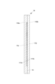
- FIG. 2 is a perspective view of a fluorescence analysis cell according to the same embodiment.
- FIG. 2 is a cross-sectional view taken along the line A-A' of the fluorescence analysis cell according to the same embodiment. It is a manufacturing method of the fluorescence analysis cell based on the same embodiment.
- FIG. 7 is a cross-sectional view taken along the line A-A' of a cell installation part according to a modified embodiment.
- FIG. 7 is a perspective view of a fluorescence analysis cell according to a modified embodiment.
- FIG. 7 is a cross-sectional view taken along the line A-A' of a fluorescence analysis cell according to a modified embodiment.
- FIG. 7 is a cross-sectional view taken along the line A-A' of a fluorescence analysis cell according to a modified embodiment.
- FIG. 7 is a cross-sectional view taken along the line A-A' of a fluorescence analysis cell according to a modified embodiment.
- the fluorescence analyzer 100 of this embodiment analyzes substances contained in the test liquid X by detecting fluorescence generated by the substances contained in the test liquid X.
- the test liquid X has an absorbance of 2 or more, for example, and specific examples of the test liquid ), beverages (for example, fruit juice, drinks containing fruit juice, beverages containing colorants, coffee, sake, beer, etc.), foods (for example, jelly, health foods, seasonings, etc.), oils, electrolytes, etc.
- the fluorescence analysis device 100 of this embodiment includes a fluorescence analysis cell 10 that contains the test liquid X, a cell installation section 20 in which the fluorescence analysis cell 10 is installed, an excitation light irradiation section 30 that irradiates excitation light L1 having a wavelength that excites a substance contained in the test liquid X, a fluorescence measurement section 40 that measures the fluorescence L2 generated in the test liquid X, a transmitted light detection section 50 that detects transmitted light L3, which is the excitation light that has passed through the fluorescence analysis cell 10, a calculation section 60 that performs calculations using the signal of the fluorescence L2 detected by the fluorescence measurement section 40 and the signal of the transmitted light L3 detected by the transmitted light detection section 50, and an output section 70 that outputs the results of calculations by the calculation section 60.
- the fluorescence analysis cell 10 accommodates the test liquid X that is the subject of fluorescence analysis.
- the cell length of the fluorescence analysis cell 10 containing the test liquid X is configured at a distance of 500 nm or more and 1 mm or less, so as shown in FIG. 1, the excitation light L1 incident on the fluorescence analysis cell 10 is In addition to becoming light L2, the light passes through the fluorescence analysis cell 10 and becomes transmitted light L3. A more detailed configuration will be described in detail.
- the cell installation section 20 is where the fluorescence analysis cell 10 is installed. Specifically, as shown in FIG. 2, the cell installation section 20 is movable relative to the main body mounting section 21 on which the fluorescence analysis cell 10 is placed in an upright state, and the main body mounting section 21.
- the cell pressing section 22 is provided and presses and fixes the fluorescence analysis cell 10 against the main body mounting section 21.
- the main body mounting section 21 includes a transmitted light passage section 211 through which the transmitted light L3 passes.
- the transmitted light passage section 211 is, for example, an opening formed in the main body mounting section 21, as shown in FIG.
- the cell installation unit 20 also installs the fluorescence analysis cell 10 in such a way that the plane perpendicular to the plane of the pair of light-transmitting members 110a and 110b on which the excitation light L1 enters is inclined with respect to the irradiation direction of the excitation light L1.
- the cell installation section 20 arranges the fluorescence analysis cell 10 so that a surface perpendicular to the surface of the light-transmitting section 11a is inclined with respect to the irradiation direction of the excitation light L1.
- the cell is installed so that the angle formed between the surface of the transparent part 11a into which the excitation light L1 enters and the direction of incidence of the excitation light L1 is 30 degrees or more and 45 degrees or less.
- the fluorescence analysis cell 10 is arranged. Since the cell installation unit 20 arranges the fluorescence analysis cell 10 in this manner, when the excitation light L1 enters the fluorescence analysis cell 10, the fluorescence L2 and transmitted light L3 are generated from the fluorescence analysis cell 10.
- the excitation light irradiation unit 30 irradiates the test liquid X with excitation light L1 having a wavelength that excites the test liquid X, and includes an excitation light source 31 such as a xenon lamp, and the light from the excitation light source 31. It includes a spectroscope 32 that performs spectroscopy, and an optical condensing system 33 that condenses excitation light L1 having a specific wavelength.
- the excitation light L1 collected by the optical focusing system 33 enters the fluorescence analysis cell 10.
- the fluorescence measurement unit 40 detects the fluorescence L2 generated in the test liquid X and transmitted through the fluorescence analysis cell 10.
- the fluorescence measurement unit 40 includes a detection side spectroscope 41 that separates the fluorescence L2 of the test liquid X irradiated with the excitation light L1, and a fluorescence detection unit 42 that detects the separated fluorescence L2.
- the fluorescence detection unit 42 calculates the fluorescence intensity indicating the intensity of the fluorescence L2 based on the detected fluorescence L2.
- a specific example of the fluorescence detection unit 42 is a CCD detector that detects fluorescence having a wavelength band of 250 nm or more and 620 nm or less, and is capable of detecting fluorescence in the ultraviolet region with a wavelength of 380 nm or less.
- the transmitted light detection section 50 detects transmitted light L3. Further, a detector (not shown) in the transmitted light detection section 50 is, for example, a silicon photodiode that detects a wavelength of 230 nm or more and 800 nm or less. Since the fluorescence analysis cell 10 in this embodiment has a cell length of 500 nm or more and 1 mm or less, the transmitted light L3 is transmitted through the fluorescence analysis cell 10, and the detector of the transmitted light detection unit 50 detects the transmitted light L3. do.
- the calculation unit 60 performs calculations using the fluorescence intensity detected by the fluorescence detection unit 42 and the transmitted light L3 detected by the transmitted light detection unit 50, and analyzes the properties of the substance contained in the test liquid X.
- the calculation unit 60 is a calculation device equipped with a CPU, an A/D converter, etc., converts the detected fluorescence intensity and transmitted light L3 with the A/D converter, and performs calculations with the CPU. By doing this, the properties of the substance contained in the test liquid X, for example, the concentration of the test liquid X, and the absorbance indicating the intensity of the transmitted light L3 with respect to the excitation light L1 are calculated.
- the calculation unit 60 uses the calculated absorbance to correct the fluorescence intensity.
- the test liquid When irradiated with a fluorescent light, a fluorescence intensity that is lower than the actual fluorescence intensity may be detected.
- the calculation unit 60 performs, for example, IFE correction.
- IFE correction here refers to correcting the fluorescence intensity by taking into account reabsorption of fluorescence (inner filter effect) by absorbing components in the test liquid when the test liquid has a high concentration.
- the correction performed on the fluorescence intensity using the absorbance is not limited to IFE correction, and may be other corrections.
- the calculation unit 60 Based on the absorbance calculated by the calculation unit 60, the calculation unit 60 calculates the influence of the inner filter effect. Thereafter, the calculation unit 60 corrects the detected fluorescence intensity to the actual fluorescence intensity by calculating the fluorescence intensity taking into account the influence of the inner filter effect.
- the output unit 70 outputs data regarding the properties of the substance analyzed by the calculation unit 60, and the output data is displayed on a display, for example.
- the fluorescence analysis cell 10 accommodates the test liquid X and is used for fluorescence analysis. Specifically, as shown in FIG. 3, the fluorescence analysis cell 10 includes a pair of flat transparent members 110a and 110b that constitute a pair of transparent parts 11a and 11b, and a pair of transparent members 110a and 110b, respectively. A spacer 120 is provided between 110a and 110b and constitutes a spacer portion 12 having a thickness of 500 nm or more and 1 mm or less.
- the thickness of the spacer portion 12 is preferably in the range of 1 ⁇ m or more and 500 ⁇ m or less, and more preferably in the range of 1 ⁇ m or more and 10 ⁇ m or less. be.
- the pair of light-transmitting members 110a and 110b have, for example, a rectangular shape, and constitute a pair of light-transmitting parts 11a and 11b that transmit the excitation light L1 emitted from the excitation light irradiation section 30, respectively.
- the material of the pair of light-transmitting members 110a and 110b is a material through which the excitation light L1 and the fluorescence L2 are transmitted, such as quartz glass.
- the light-transmitting member 110a is arranged on the side of the excitation light irradiation section 30, and the fluorescence L2 is emitted from the light-transmitting section 11a that constitutes the light-transmitting member 110a.
- the light-transmitting member 110b is arranged on the side of the transmitted light detection unit 50, and the transmitted light L3 is emitted from the light-transmitting portion 11b that constitutes the light-transmitting member 110b.
- the spacer 120 has an annular shape, and in this embodiment, it has a rectangular frame shape.
- the spacer 120 constitutes a spacer section 12 that defines the distance between the opposing surfaces 111a and 111b of the pair of light-transmitting sections 11a and 11b.
- the material of the spacer 120 is a material that has corrosion resistance against the test liquid X and does not generate impurities in the test liquid X, and is made of stainless steel, for example.
- the shape of the spacer is not limited to a rectangular frame shape, but may be any hollow shape such as a circular frame shape.
- the spacer 120 is provided in contact with the pair of light-transmitting members 110a and 110b.
- the spacer 120 makes the opposing surfaces 111a, 111b of the pair of transparent parts 11a, 11b parallel to each other, and sets the distance between these opposing surfaces 111a, 111b to a predetermined distance (for example, 500 nm or more and 1 mm or less).
- the pair of light-transmitting members 110a and 110b constitute a pair of light-transmitting parts 11a and 11b, respectively, inside the spacer 120.
- the spacer portion 12 and the pair of light-transmitting portions 11a and 11b form an internal space in which the test liquid X is accommodated.
- the spacer portion 12 by providing a spacer 120 between the pair of light-transmitting members 110a and 110b, the spacer portion 12
- the inner circumferential surface 12a of the test liquid X forms an internal space that accommodates the test liquid X.
- the fluorescence analysis cell 10 becomes an analysis target cell S, which is a target of fluorescence analysis, by storing the test liquid X in this internal space.
- An annular spacer 120 having a thickness of 500 nm or more and 1 mm or less is provided overlappingly on the opposing surface 111a of one of the pair of light-transmitting members 110a and 110b, for example, the light-transmitting member 110a (FIG. 4 (see (a)). As a result, a space is formed that is surrounded by the opposing surface 111a of the light-transmitting member 110a and the inner circumferential surface 12a of the annular spacer 120.
- test liquid X is accommodated in the space formed by the opposing surface 111a of the light-transmitting member 110a and the inner circumferential surface 12a of the spacer 120 (see FIG. 4(b)).
- the other light-transmitting member 110b is placed on the upper surface of the spacer 120 so as to cover the test liquid X (see FIG. 4(c)). As a result, the test liquid It is enclosed in the internal space to be formed. As a result, the cell S to be analyzed is produced (see FIG. 4(d)).
- the analysis target cell S prepared by this method is placed upright on the main body placing part 21 of the cell setting part 20, and is pressed against the main body placing part 21 by the cell pressing part 22. It is fixed by pressing.
- the test liquid X is accommodated in an internal space formed by the opposing surfaces 111a, 111b of the pair of light-transmitting parts 11a, 11b and the inner peripheral surface 12a of the spacer part 12. Since the spacer part 12 has a distance between the opposing surfaces 111a, 111b of 500 nm or more and 1 mm or less, the distance that the fluorescence generated in the test liquid X takes to reach the surface of the fluorescence analysis cell 10 is smaller than that of a rectangular cell. As a result, it is possible to reduce the reabsorption of the fluorescence of the test liquid X generated inside the cell.
- the present invention is particularly effective when the test liquid X is diluted and its physical properties are affected, for example, when the test liquid X is a liquid whose physical properties are affected by changes in the coordination of a solvent or coexisting solute.
- the fluorescence analyzer 100 may further include an adjustment mechanism 23 that adjusts the relative position between the condensing position of the excitation light L1 and the position of the fluorescence analysis cell 10.
- an adjustment mechanism 23 that adjusts the relative position between the condensing position of the excitation light L1 and the position of the fluorescence analysis cell 10.
- a thickness is provided between the main body mounting portion 21 and the fluorescence analysis cell 10 to match the condensing position of the excitation light L1 and the surface position of the test liquid X. It is conceivable to provide an adjustment spacer 231.
- the light-transmitting member 110a moves in the direction of incidence of the excitation light L1 according to the thickness of the adjustment spacer 231, so that the condensing position of the excitation light L1 and the test liquid It is possible to match the surface position.
- the excitation light L1 is focused on the surface of the test liquid X, so more fluorescence is generated on the surface of the test liquid X, and reabsorption of fluorescence becomes less likely to occur. Therefore, measurement errors caused by fluorescence reabsorption can be reduced.
- the adjustment mechanism 23 is provided with an adjustment spacer 231 having a thickness that matches the condensing position of the excitation light L1 and the surface position of the test liquid X; It is not limited to the spacer 231.
- the adjustment mechanism 23 may be an adjustment mechanism 23 that adjusts the relative position by moving the cell installation section 20 itself relative to the incident direction of the excitation light L1.
- this adjustment mechanism 23 may adjust the above-mentioned relative position by moving the condensing position of the excitation light L1 of the excitation light irradiation section 30.
- the fluorescence analysis cell 10 may further include a clamping member 13 that clamps and fixes the pair of light-transmitting members 110a, 110b.
- the distance between the opposing surfaces of the pair of light-transmitting parts 11a, 11b is fixed, and therefore the optical path length of the excitation light L1 is also fixed.
- the holding member 13 sandwiches and fixes the pair of light-transmitting members 110a, 110b, it is possible to prevent the pair of light-transmitting members 110a, 110b from shifting and leaking the test liquid X from the fluorescence analysis cell 10. can.
- the pair of light-transmitting members 110a and 110b can be prevented from being displaced by the holding member 13, the work from manufacturing the fluorescence analysis cell 10 to installing the fluorescence analysis cell 10 in the cell installation section 20 is performed. can be made easier.
- the spacer 120 constitutes the spacer portion 12 having a thickness of 500 nm or more and 1 mm or less, but the thickness of the spacer 120 is not limited to this.
- the transparent parts around the pair of transparent parts 11a and 11b are set such that the distance between the opposing surfaces 111a and 111b of the pair of transparent parts 11a and 11b is 500 nm or more and 1 mm or more.
- An example of this is to reduce the thickness of the optical member and increase the thickness of the spacer 120.
- the fluorescence analysis cell 10 may have a structure in which the spacer portion 12 is integrally provided in at least one of the pair of light-transmitting members 110a and 110b.
- the distance between the opposing surfaces 111a and 111b of the pair of transparent parts 11a and 11b is 500 nm or more and 1 mm or less. It is conceivable to provide the spacer portion 12 integrally.
- the fluorescence analysis cell 10 can include the spacer section 12 without providing the spacer 120. Note that a configuration may be adopted in which both of the pair of light-transmitting members 110a and 110b are provided with a convex portion that constitutes the spacer portion 12.
- the fluorescence analysis cell 10 is configured as a batch cell in which the test liquid X is placed in the fluorescence analysis cell 10 for each analysis and subjected to fluorescence analysis, but it may also be configured as a flow cell in which the test liquid X is introduced into and discharged from the fluorescence analysis cell 10. That is, as shown in FIG. 9, the fluorescence analysis cell 10 may be configured to include an introduction section 14 that introduces the test liquid X into the internal space, and an outlet section 15 that discharges the test liquid X from the internal space. In this case, the fluorescence analysis device 100 can perform fluorescence analysis by continuously or intermittently circulating the test liquid X through the fluorescence analysis cell 10.
- the distance between the opposing surfaces 111a and 111b of the pair of transparent parts 11a and 11b was constant, but a configuration may be adopted in which the distance between the opposing surfaces changes. That is, as shown in FIG. 10, by making one of the opposing surfaces 111a a stepped surface 114 having a stepped shape, for example, a configuration in which the distance between the opposing surfaces changes can be achieved. As a result, since there are a plurality of distances between the opposing surfaces, which are the optical path lengths of the excitation light L1, it is possible to measure the absorbance of the test liquid X for a plurality of optical path lengths in one measurement.
- the fluorescence analyzer 100 was configured to include the transmitted light detection section 50, but it may not include the transmitted light detection section 50. In this case, the fluorescence analyzer 100 can perform fluorescence analysis without the need to measure absorbance.
Landscapes
- Health & Medical Sciences (AREA)
- Biochemistry (AREA)
- Physics & Mathematics (AREA)
- Life Sciences & Earth Sciences (AREA)
- Chemical & Material Sciences (AREA)
- Analytical Chemistry (AREA)
- General Health & Medical Sciences (AREA)
- General Physics & Mathematics (AREA)
- Immunology (AREA)
- Pathology (AREA)
- Nuclear Medicine, Radiotherapy & Molecular Imaging (AREA)
- Optical Measuring Cells (AREA)
- Investigating, Analyzing Materials By Fluorescence Or Luminescence (AREA)
Abstract
L'invention concerne une cellule d'analyse par fluorescence (10) destinée à être utilisée dans une analyse par fluorescence sur un liquide X d'intérêt, la cellule d'analyse par fluorescence (10) comprenant une paire de parties translucides (11a, 11b) opposées l'une à l'autre, entre lesquelles se situe un espace interne contenant le liquide X d'intérêt et une partie d'espacement (12) prévue pour entourer l'espace interne de sorte que la distance entre des surfaces opposées (111a, 111b) de la paire de parties translucides (11a, 11b) est de 500 nm à 1 mm compris.
Applications Claiming Priority (2)
| Application Number | Priority Date | Filing Date | Title |
|---|---|---|---|
| JP2022-151742 | 2022-09-22 | ||
| JP2022151742 | 2022-09-22 |
Publications (1)
| Publication Number | Publication Date |
|---|---|
| WO2024062833A1 true WO2024062833A1 (fr) | 2024-03-28 |
Family
ID=90454101
Family Applications (1)
| Application Number | Title | Priority Date | Filing Date |
|---|---|---|---|
| PCT/JP2023/030431 WO2024062833A1 (fr) | 2022-09-22 | 2023-08-24 | Cellule d'analyse par fluorescence, dispositif d'analyse par fluorescence, procédé d'analyse par fluorescence et procédé de fabrication de cellule à soumettre à une analyse |
Country Status (1)
| Country | Link |
|---|---|
| WO (1) | WO2024062833A1 (fr) |
Citations (8)
| Publication number | Priority date | Publication date | Assignee | Title |
|---|---|---|---|---|
| JPH01253635A (ja) * | 1988-04-01 | 1989-10-09 | Hitachi Ltd | 蛍光分析方法及びその装置 |
| JPH0835927A (ja) * | 1994-07-25 | 1996-02-06 | Jasco Corp | 蛍光検出用フローセル及びそれを用いた蛍光検出器 |
| JP2003515724A (ja) * | 1998-10-09 | 2003-05-07 | ユニバーシティ オブ ワシントン | デュアル広角(duallargeangle)光散乱検出 |
| JP2008196943A (ja) * | 2007-02-13 | 2008-08-28 | Matsushita Electric Ind Co Ltd | 生物学的特異的反応物質の測定チップ、測定システムおよび測定方法 |
| WO2008130032A1 (fr) * | 2007-04-19 | 2008-10-30 | The Ritsumeikan Trust | Dispositif de classement de particules immergées, procédé de classement de particules immergées, dispositif de mesure de diamètre de particule et procédé de mesure de diamètre de particule |
| WO2017199511A1 (fr) * | 2016-05-19 | 2017-11-23 | 富士電機株式会社 | Analyseur de qualité de l'eau |
| JP2018532998A (ja) * | 2015-09-14 | 2018-11-08 | エッセンリックス コーポレーション | 試料、特に血液を分析するための装置及びシステム、並びにそれらの使用方法 |
| JP2019211455A (ja) * | 2017-06-22 | 2019-12-12 | 株式会社堀場製作所 | 光学測定用セル及びこれを用いた粒子物性測定装置 |
-
2023
- 2023-08-24 WO PCT/JP2023/030431 patent/WO2024062833A1/fr unknown
Patent Citations (8)
| Publication number | Priority date | Publication date | Assignee | Title |
|---|---|---|---|---|
| JPH01253635A (ja) * | 1988-04-01 | 1989-10-09 | Hitachi Ltd | 蛍光分析方法及びその装置 |
| JPH0835927A (ja) * | 1994-07-25 | 1996-02-06 | Jasco Corp | 蛍光検出用フローセル及びそれを用いた蛍光検出器 |
| JP2003515724A (ja) * | 1998-10-09 | 2003-05-07 | ユニバーシティ オブ ワシントン | デュアル広角(duallargeangle)光散乱検出 |
| JP2008196943A (ja) * | 2007-02-13 | 2008-08-28 | Matsushita Electric Ind Co Ltd | 生物学的特異的反応物質の測定チップ、測定システムおよび測定方法 |
| WO2008130032A1 (fr) * | 2007-04-19 | 2008-10-30 | The Ritsumeikan Trust | Dispositif de classement de particules immergées, procédé de classement de particules immergées, dispositif de mesure de diamètre de particule et procédé de mesure de diamètre de particule |
| JP2018532998A (ja) * | 2015-09-14 | 2018-11-08 | エッセンリックス コーポレーション | 試料、特に血液を分析するための装置及びシステム、並びにそれらの使用方法 |
| WO2017199511A1 (fr) * | 2016-05-19 | 2017-11-23 | 富士電機株式会社 | Analyseur de qualité de l'eau |
| JP2019211455A (ja) * | 2017-06-22 | 2019-12-12 | 株式会社堀場製作所 | 光学測定用セル及びこれを用いた粒子物性測定装置 |
Similar Documents
| Publication | Publication Date | Title |
|---|---|---|
| EP1730495B1 (fr) | Detecteur de concentration d'ozone | |
| CN108351304B (zh) | 水质分析仪 | |
| JP5419301B2 (ja) | 試料分析装置 | |
| US10132787B2 (en) | Device for optically determining the concentration of alcohol and carbohydrates in a liquid sample | |
| JP2008309785A (ja) | 減衰全反射センサー | |
| JP5743558B2 (ja) | 分析装置 | |
| KR20160137019A (ko) | 광학 센서를 이용한 수질 오염 측정 시스템 및 수질 오염 측정 장치 | |
| KR20120079941A (ko) | 수용액 내 존재하는 우라늄 농도의 정량방법 | |
| KR20110067049A (ko) | 고농도 기체의 스펙트럼 분석에 적합한 장치 | |
| JPWO2019176624A1 (ja) | ガス分析方法及び装置 | |
| KR20170052256A (ko) | 라만 산란을 이용한 물질의 농도 측정 장치 및 방법 | |
| JP5272965B2 (ja) | 蛍光検出器 | |
| KR101803676B1 (ko) | 컴팩트형 비분산 적외선 가스 분석장치 | |
| WO2024062833A1 (fr) | Cellule d'analyse par fluorescence, dispositif d'analyse par fluorescence, procédé d'analyse par fluorescence et procédé de fabrication de cellule à soumettre à une analyse | |
| US20170227397A1 (en) | Analyte system and method for determining hemoglobin parameters in whole blood | |
| US9541531B2 (en) | Detector for liquid chromatography | |
| JP4218954B2 (ja) | 吸光式分析計 | |
| JP2002098631A (ja) | 小型試料濃度測定装置 | |
| JP2010249726A (ja) | ガス分析装置 | |
| KR20150136760A (ko) | 가스 측정 센서 및 방법 | |
| US20230296438A1 (en) | Absorbance spectroscopy analyzer and method of use | |
| CN110879208A (zh) | 一种带自校准功能的吸光度检测系统 | |
| JP2006275794A5 (fr) | ||
| US9933411B2 (en) | Analyte system and method for determining hemoglobin parameters in whole blood | |
| WO2023112358A1 (fr) | Spectrophotomètre |
Legal Events
| Date | Code | Title | Description |
|---|---|---|---|
| 121 | Ep: the epo has been informed by wipo that ep was designated in this application |
Ref document number: 23867957 Country of ref document: EP Kind code of ref document: A1 |