WO2024058186A1 - 電気接続箱 - Google Patents
電気接続箱 Download PDFInfo
- Publication number
- WO2024058186A1 WO2024058186A1 PCT/JP2023/033258 JP2023033258W WO2024058186A1 WO 2024058186 A1 WO2024058186 A1 WO 2024058186A1 JP 2023033258 W JP2023033258 W JP 2023033258W WO 2024058186 A1 WO2024058186 A1 WO 2024058186A1
- Authority
- WO
- WIPO (PCT)
- Prior art keywords
- bus bar
- holes
- heat
- connection box
- side wall
- Prior art date
- Legal status (The legal status is an assumption and is not a legal conclusion. Google has not performed a legal analysis and makes no representation as to the accuracy of the status listed.)
- Ceased
Links
Images




Classifications
-
- H—ELECTRICITY
- H05—ELECTRIC TECHNIQUES NOT OTHERWISE PROVIDED FOR
- H05K—PRINTED CIRCUITS; CASINGS OR CONSTRUCTIONAL DETAILS OF ELECTRIC APPARATUS; MANUFACTURE OF ASSEMBLAGES OF ELECTRICAL COMPONENTS
- H05K5/00—Casings, cabinets or drawers for electric apparatus
- H05K5/02—Details
- H05K5/0213—Venting apertures; Constructional details thereof
-
- H—ELECTRICITY
- H02—GENERATION; CONVERSION OR DISTRIBUTION OF ELECTRIC POWER
- H02G—INSTALLATION OF ELECTRIC CABLES OR LINES, OR OF COMBINED OPTICAL AND ELECTRIC CABLES OR LINES
- H02G3/00—Installations of electric cables or lines or protective tubing therefor in or on buildings, equivalent structures or vehicles
- H02G3/02—Details
- H02G3/08—Distribution boxes; Connection or junction boxes
- H02G3/16—Distribution boxes; Connection or junction boxes structurally associated with support for line-connecting terminals within the box
-
- H—ELECTRICITY
- H02—GENERATION; CONVERSION OR DISTRIBUTION OF ELECTRIC POWER
- H02G—INSTALLATION OF ELECTRIC CABLES OR LINES, OR OF COMBINED OPTICAL AND ELECTRIC CABLES OR LINES
- H02G3/00—Installations of electric cables or lines or protective tubing therefor in or on buildings, equivalent structures or vehicles
- H02G3/02—Details
- H02G3/08—Distribution boxes; Connection or junction boxes
- H02G3/081—Bases, casings or covers
-
- H—ELECTRICITY
- H05—ELECTRIC TECHNIQUES NOT OTHERWISE PROVIDED FOR
- H05K—PRINTED CIRCUITS; CASINGS OR CONSTRUCTIONAL DETAILS OF ELECTRIC APPARATUS; MANUFACTURE OF ASSEMBLAGES OF ELECTRICAL COMPONENTS
- H05K7/00—Constructional details common to different types of electric apparatus
- H05K7/20—Modifications to facilitate cooling, ventilating, or heating
- H05K7/20009—Modifications to facilitate cooling, ventilating, or heating using a gaseous coolant in electronic enclosures
- H05K7/20127—Natural convection
Definitions
- Patent Document 1 discloses an electrical connection device including a housing that accommodates an electromagnetic relay, and in which the housing is provided with an opening in the vicinity of the electromagnetic relay to radiate heat inside the housing to the outside. Disclosed.
- An electrical connection box includes a housing having a fixed wall fixed to an object and provided with electronic components, and a board arranged opposite to the fixed wall and connected to the electronic component.
- the electrical connection box is provided with a shaped bus bar, and is provided with a plurality of heat radiating plates that are erected in a direction intersecting the bus bar and radiate heat from the bus bar.
- FIG. 1 is a perspective view of an electrical connection box according to Embodiment 1.
- FIG. 1 is a plan view of an electrical connection box according to Embodiment 1.
- FIG. FIG. 2 is a plan view showing the electrical connection box according to the first embodiment with the upper case removed.
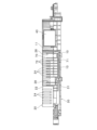
- FIG. 4 is a view taken along arrow IV in FIG. 3; 3 is a sectional view taken along line VV in FIG. 2.
- FIG. 3 is a partial plan view of an electrical connection box according to a second embodiment.
- FIG. 7 is a partial vertical cross-sectional view of an electrical connection box according to Embodiment 3;
- FIG. 7 is a plan view of the electrical connection box of Embodiment 4 with the upper case removed.
- the opening is provided in the housing at a position near the electromagnetic relay, and heat is only radiated to the electromagnetic relay itself, and heat radiation through the bus bar is not devised. Therefore, it is difficult to say that the heat from the electromagnetic relay is dissipated efficiently.
- An electrical junction box includes a housing that has a fixed wall that is fixed to an object and is provided with an electronic component, and a housing that is arranged to face the fixed wall and is connected to the electronic component.
- the electrical connection box is provided with a board-shaped bus bar, and is provided with a plurality of heat radiating plates that are erected in a direction intersecting with the bus bar and radiate heat from the bus bar.
- the heat generated in the electronic component during energization and transmitted to the bus bar can be quickly radiated, and the heat can be radiated from the electronic component more effectively.
- the electrical junction box according to the embodiment of the present disclosure includes a base plate whose first main surface is in contact with one main surface of the bus bar, and the plurality of heat sinks are provided on the second main surface of the base plate. It is being
- heat generated in the electronic component when energized is transmitted to the bus bar, and is conducted to the plurality of heat sinks via the base plate, and the plurality of heat sinks quickly radiate the heat. . Therefore, heat can be effectively radiated from the electronic component.
- a first through hole is formed in a facing wall facing the fixed wall, and the first through hole is formed in a facing wall opposite to the fixed wall and the facing wall. It is formed at a position corresponding to the gap between adjacent heat sinks in the direction.
- the first through hole is formed at a position corresponding to a gap between adjacent heat sinks in the opposing direction. Therefore, the outside air flowing into the housing from the first through hole quickly flows into the gap between the heat sinks, air-cools the heat sinks, and fills the gap between the heat sinks containing the radiated heat. The air rises and quickly flows out of the housing through the first through hole. Therefore, heat can be effectively radiated from the electronic component.
- the first through hole extends along the heat sink.
- the size of the first through hole can be adjusted at a portion of the opposing wall corresponding to the gap between adjacent heat sinks. can be effectively ensured.
- side walls extending toward the fixed wall are connected to both opposing edges of the opposing wall, and a second through hole is formed in each side wall.
- the second through-holes are formed in opposing directions of the two side walls at positions corresponding to gaps between adjacent heat sinks.
- the second through holes are formed in positions corresponding to the gaps between adjacent heat sinks in the opposing direction of the two side walls, the second through holes of the one side wall Air flowing in through the through holes passes between adjacent heat sinks, and quickly flows out from the second through hole in the other side wall. At this time, since the heat convected from the heat sink also flows to the outside of the housing, the cooling effect of the electronic components can be further enhanced.
- the second through hole extends along the heat sink.
- the second through hole extends along the heat sink, the second through hole extends in a portion of the two side walls that corresponds to the gap between adjacent heat sinks. The size can be effectively secured.
- the base plate and the plurality of heat sinks are integrally formed, and the opposing wall is provided with a positioning part that determines the position of the heat sink. There is.
- the positioning portion is used to determine the position of the heat sink during assembly, so the workability of the assembly work can be improved.
- the heat sink is provided in the vicinity of a connection portion between the bus bar and the electronic component.
- the heat sink is also provided near the connection portion between the bus bar and the electronic component. Therefore, it is possible to more efficiently cool down the connection portion, which generates heat intensively when energized.
- the number of heat sinks is greater in the vicinity of the connection portion than in other parts.
- the number of heat sinks near the connection portion between the bus bar and the electronic component is greater than in other parts. Therefore, it is possible to more efficiently cool down the connection portion, which generates heat intensively when energized.
- the electrical connection box according to the embodiment of the present disclosure includes a plurality of first through holes, and one of the plurality of first through holes is formed near a connecting portion between the bus bar and the electronic component. One of the first through holes is larger than the other first through holes.
- the size of one first through hole formed near the connection portion is larger than the other first through holes. Therefore, the inflow of outside air into the connection part and the outflow of air containing heat radiated from the connection part are increased, and the heat generated in the connection part when electricity is applied can be cooled more efficiently.
- the electrical connection box according to the embodiment of the present disclosure includes a plurality of second through holes, and one of the plurality of second through holes is formed near a connecting portion between the bus bar and the electronic component. One of the second through holes is larger than the other second through holes.
- the second through hole provided near the connection portion is larger than the other second through holes. Therefore, the inflow of outside air into the connection part and the outflow of air containing heat radiated from the connection part are increased, and the heat generated in the connection part when electricity is applied can be cooled more efficiently.
- FIG. 1 is a perspective view of an electrical junction box 100 according to the first embodiment
- FIG. 2 is a plan view of the electrical junction box 100 according to the first embodiment.
- the positions of a bus bar 10 and a heat radiating member 70, which will be described later, are indicated by broken lines.
- the electrical connection box 100 is attached to the outside of an object to which it is attached, such as a battery pack 200 of an EV (Electric Vehicle), for example.
- FIG. 1 shows a state in which the electrical connection box 100 is attached to the battery pack 200.
- the electrical connection box 100 includes, for example, a housing 50 in which a relay 40 (electronic component), a fuse 60 (electronic component), a board, etc. are housed.
- the housing 50 has a substantially rectangular shape in plan view, and is made of resin, for example.
- the housing 50 includes a lower case 30 that is attached to the mounting target, and an upper case 20 that partially covers the lower case 30.
- Electronic components such as a relay 40, a fuse 60, and a bus bar 10 are attached to the lower case 30, and the upper case 20 covers some of these electronic components.
- the upper case 20 side will be described as the top and the lower case 30 side will be described as the bottom.
- FIG. 3 is a plan view showing the electrical connection box 100 according to the first embodiment with the upper case 20 removed
- FIG. 4 is a view taken along arrow IV in FIG. 3.
- the lower case 30 has a flat box shape with one side open on the upper case 20 side.
- the lower case 30 has a substantially rectangular bottom wall 31 (fixed wall) whose outer side is fixed in contact with the mounting target, and a side wall 33 extending perpendicularly from the edge of the bottom wall 31 toward the upper case 20 side. .
- the relay 40, the fuse 60, and the bus bar 10 are provided inside the lower case 30.
- engagement protrusions 35 that engage with engagement portions 25 of the upper case 20, which will be described later, are protrudingly provided at a plurality of locations on the outer surface of the side wall 33 on the long side of the bottom wall 31. ing.
- the engagement protrusion 35 consists of a pair of protrusions separated from each other in the length direction of the side wall 33.
- fixing holes 37 are formed at the four corners and near the side wall 33 on one long side, which are used when attaching the lower case 30 (casing 50) to a mounting target.
- the lower case 30 is provided with a relay 40 and a fuse 60 separated from each other in the length direction of the lower case 30. That is, the relay 40 is disposed at one end of the lower case 30, and the fuse 60 is disposed at the other end of the lower case 30.
- the fuse 60 is provided near one side wall 33 of the lower case 30 in the width direction. Further, the relay 40 is provided with a connection terminal on the other side wall 33 side in the width direction (see FIG. 4).
- a bus bar 10 is provided between the relay 40 and the fuse 60.
- the bus bar 10 has a substantially plate shape, is made of a conductive metal plate such as copper, and is disposed to face the inner surface of the bottom wall 31 .
- the bus bar 10 has a flat part 13 facing the bottom wall 31, one end part 11 (connection part) screwed to the connection terminal of the relay 40, and the other end part 12 screwed to the connection terminal 61 of the fuse 60. (connection part).
- connection part screwed to the connection terminal of the relay 40
- connection part 12 screwed to the connection terminal 61 of the fuse 60.
- the bus bar 10 has the rectangular plate-shaped other end 12 connected perpendicularly to the flat part 13 at the edge near the fuse 60, and the other end 12 in the flat part 13 near the relay 40.
- One end portion 11 in the shape of a rectangular plate is connected perpendicularly to the flat portion 13 at the edge.
- the one end portion 11 extends in the width direction of the bottom wall 31, and the end portion on the other side wall 33 side is bent along the other side wall 33 and connected to the connection terminal of the relay 40. There is.
- One end 11 and the other end 12 are provided with fixing through holes for screwing.
- oval fixed through holes are formed in the other end 12 and the one end 11, thereby making it possible to accommodate design errors and tolerances.
- the bus bar 10 is provided such that one main surface of the flat portion 13 faces the bottom wall 31.
- a heat radiating member 70 is screwed to the flat portion 13 of the bus bar 10 to radiate heat generated by the bus bar 10 when energized.
- a heat radiating member 70 is provided over most of the flat portion 13, including the vicinity of the one end 11 and the other end 12.
- the heat dissipation member 70 has a comb shape in a longitudinal cross-sectional view extending in the length direction of the lower case 30, and includes a base plate 71 and a plurality of heat dissipation fins 72 (heat dissipation plates).
- the base plate 71 is made of a material with good thermal conductivity, such as aluminum, and has a substantially rectangular shape.
- One principal surface (first principal surface) of the base plate 71 is in contact with the other principal surface of the flat portion 13 of the bus bar 10 .
- a plurality of radiation fins 72 are provided on the other main surface (second main surface) of the base plate 71 .
- Each radiation fin 72 has a rectangular plate shape and is made of the same material as the base plate 71.
- the radiation fins 72 and the base plate 71 are integrally formed.
- the heat dissipation fins 72 are erected substantially perpendicularly from the base plate 71.
- the radiation fins 72 are arranged in parallel at predetermined intervals in the longitudinal direction of the bottom wall 31 .
- the upper case 20 has a box shape with one side open on the lower case 30 side.
- the upper case 20 is slightly smaller than the lower case 30 in a length direction and a width direction perpendicular to the length direction.
- the upper case 20 has a ceiling wall 21 facing the bottom wall 31 of the lower case 30, and a side wall 22 that is provided around the edge of the ceiling wall 21 and extends toward the lower case 30 (see FIG. 1). .
- a plurality of through holes 23 are formed in the ceiling wall 21. More specifically, a plurality of through holes 23 are formed in most of the ceiling wall 21 including the vicinity of the bus bar 10 . A plurality of through holes 23 are formed along the ceiling wall 21.
- the through holes 23 provided near the bus bar 10 are adjacent to each other in the opposing direction between the ceiling wall 21 and the bottom wall 31 of the lower case 30 (hereinafter simply referred to as the opposing direction). It is formed at a position corresponding to the gap between the matching heat radiation fins 72 (see FIG. 2). In other words, the area directly below each through hole 23 corresponds to the space between adjacent radiation fins 72 . Further, each through hole 23 has a substantially rectangular shape extending along the radiation fin 72. In particular, the through hole 23 provided near the bus bar 10 extends along the gap between adjacent radiation fins 72 .
- FIG. 5 is a sectional view taken along line VV in FIG. 2. Furthermore, a positioning portion 28 is provided protruding from the inner surface of the ceiling wall 21 to determine the position of the heat radiating member 70 (radiating fin 72) during assembly work. Positioning portions 28 are provided near the radiation fins 72 at both ends in the direction in which the radiation fins 72 are arranged side by side. Specifically, in the opposing direction, the position corresponding to the gap between the radiation fin 72 at one end and the adjacent radiation fin 72 among the radiation fins 72 at both ends, or the radiation fin 72 at the other end and the radiation adjacent thereto. A positioning portion 28 is provided at a position corresponding to the gap between the fins 72. Each positioning portion 28 has a rectangular shape when viewed in longitudinal section, and the position of the heat radiating member 70 is determined by the tip portion coming into contact with the inner surface of the heat radiating fin 72 at the end.
- a plurality of side wall through holes 24 are formed in the two side walls 22 facing each other in the width direction of the ceiling wall 21, extending to the edge of the ceiling wall 21. That is, a plurality of side wall through holes 24 are formed in one side wall 22 facing the fuse 60 and the other side wall 22 facing the connection terminal of the relay 40.
- the side wall through holes 24 are particularly formed in a concentrated manner near the bus bar 10, that is, near the through holes 23.
- the side wall through holes 24 are formed at regular intervals in the length direction of the upper case 20.
- the side wall through holes 24 of the one side wall 22 and the side wall through holes 24 of the other side wall 22 are formed in the width direction of the ceiling wall 21 (that is, in the opposing direction of the one side wall 22 and the other side wall 22). ) are formed at mutually aligned positions. Further, the side wall through holes 24 of the one side wall 22 and the side wall through holes 24 of the other side wall 22 are formed at positions corresponding to gaps between adjacent radiation fins 72 in the width direction of the ceiling wall 21. (See Figures 2 and 5).
- the radiation fins 72 are not located between the side wall through holes 24 of the one side wall 22 and the side wall through holes 24 of the other side wall 22, which correspond in the width direction of the ceiling wall 21. A gap is formed between the heat radiation fins 72 that fit together.
- the side wall through hole 24 of the one side wall 22 and the side wall through hole 24 of the other side wall 22 have a substantially rectangular shape extending along the opposing direction.
- the side wall through hole 24 provided near the bus bar 10 extends along the gap between adjacent radiation fins 72 .
- each through hole 23 and each side wall through hole 24 of the upper case 20 has a width of several mm, for example, so that a fingertip of a person handling it cannot fit therein.
- the side wall 22 is provided with engaging portions 25 that engage with the engaging protrusions 35 of the lower case 30 at multiple locations on the lower end.
- the engaging portion 25 has a U-shape, both open end portions are fixed to the side wall 22, and the curved portion projects downward from the side wall 22.
- a current in the range of 300A to 1000A is used.
- heat is generated from the relay 40 and fuse 60, and the heat from the relay 40 and fuse 60 is immediately transferred to the bus bar 10 that is in direct contact with it.
- the heat emitted from the relay 40 and the fuse 60 may have a negative effect on the electronic components around the relay 40, the fuse 60, and the bus bar 10, so it is necessary to cool them down quickly.
- the heat dissipation effect of heat dissipation from the relay 40 and fuse 60 itself cannot be expected to be large, and heat dissipation via the bus bar 10 connected to the relay 40 and fuse 60 is more efficient.
- the heat radiating member 70 is provided on the bus bar 10.
- the heat transferred from the relay 40 and fuse 60 to the bus bar 10 and the heat generated in the bus bar 10 are quickly transferred to the base plate 71 of the heat dissipation member 70 that is in direct contact with the bus bar 10 and are dissipated into the air via the heat dissipation fins 72.
- Heat is radiated to Therefore, the heat generated from the relay 40 and the fuse 60 can be efficiently dissipated via the bus bar 10, and the heat generated at the bus bar 10 can also be appropriately dissipated, so that the above-mentioned problems can be prevented in advance.
- a large current for example, 1000 A
- a large current cannot be used for a long time due to safety issues and the problem that a large amount of heat is generated in the bus bar 10, and is used intermittently for short periods of time.
- the time for the large current to flow is short, so rather than generating heat in the entire bus bar 10, heat is generated at the connection part with the relay 40 and fuse 60, that is, at both ends 11 and 12 of the bus bar 10. A concentrated fever occurs.
- heat radiating members 70 are also provided near one end 11 and the other end 12 of the bus bar 10. Therefore, as described above, even when a large current flows and heat is concentrated at both ends 11 and 12 of the bus bar 10, the heat from the bus bar 10, the relay 40, and the fuse 60 can be effectively radiated.
- the through hole 23 and the side wall through hole 24 are formed in the upper case 20 near the bus bar 10, as described above. Therefore, air can easily flow into the bus bar 10 and the heat radiating member 70 from the outside, and the air cooling effect can be enhanced.
- the through hole 23 of the upper case 20 is located at a position corresponding to the gap between the adjacent radiation fins 72 in the direction in which the ceiling wall 21 and the bottom wall 31 face each other. is formed. Further, the side wall through hole 24 of the upper case 20 is formed at a position corresponding to the gap between adjacent radiation fins 72 in the width direction of the ceiling wall 21. Therefore, external air flows into the space between the adjacent radiation fins 72 and internal air flows out from between the adjacent radiation fins 72 without stagnation.
- the side wall through hole 24 of the one side wall 22 and the side wall through hole 24 of the other side wall 22 are formed at positions aligned with each other in the width direction of the ceiling wall 21, A gap between adjacent radiation fins 72 is formed between the side wall through hole 24 of the side wall 22 on one side and the side wall through hole 24 of the side wall 22 on the other side.
- the through hole 23 provided near the bus bar 10 is formed at a position corresponding to the gap between the adjacent radiation fins 72 in the opposing direction between the ceiling wall 21 and the bottom wall 31 of the lower case 30. has been done. Therefore, when air containing heat convected from the radiation fins 72 rises from between the adjacent radiation fins 72, it quickly flows to the outside of the housing 50 through the through hole 23 directly above. Therefore, the effect of cooling the relay 40, fuse 60, and bus bar 10 can be further enhanced.
- FIG. 6 is a partial plan view of the electrical connection box 100 according to the second embodiment.
- the vicinity of the bus bar 10 is shown in an enlarged manner, and the positions of the bus bar 10 and the heat radiating member 70 are shown with broken lines.
- a plurality of through holes 23 are formed in the vicinity of the bus bar 10 in the ceiling wall 21 of the upper case 20, and a plurality of through holes 23 (first through holes) are formed in the vicinity of the bus bar 10 in the ceiling wall 21 of the upper case 20.
- a plurality of side wall through holes 24 are formed near the.
- the through hole 23 provided near the bus bar 10 is formed at a position corresponding to the gap between adjacent radiation fins 72 in the opposing direction between the ceiling wall 21 and the bottom wall 31, as in the first embodiment. That is, the area directly below each through hole 23 corresponds to the space between adjacent radiation fins 72 .
- Each through hole 23 extends along the radiation fin 72 and has a substantially rectangular shape.
- the through holes 23A formed near one end 11 and the other end 12 of the bus bar 10 are larger than the other through holes 23. It is formed.
- the size of the through hole 23A in the direction in which the plurality of through holes 23 are lined up is larger than the other through holes 23.
- the through hole 23A formed near the one end 11 and the other end 12 of the bus bar 10 is different from the other through hole 23. larger than Therefore, the amount of air flowing in from the through hole 23A becomes relatively large, and thereby the one end 11 and the other end 12 can be cooled more intensively, and a large current flows to both ends of the bus bar 10. 11 and 12 can handle cases where heat generation is concentrated.
- Embodiment 1 The same parts as in Embodiment 1 are given the same reference numerals and detailed explanations are omitted.
- FIG. 7 is a partial vertical cross-sectional view of the electrical connection box 100 according to the third embodiment.
- the vicinity of the heat radiating member 70 is shown in an enlarged manner, and the position of the other end portion 12 is shown with a chain line.
- a plurality of through holes 23 are formed in the vicinity of the bus bar 10 in the ceiling wall 21 of the upper case 20, and a plurality of through holes 23 (first through holes) are formed in the vicinity of the bus bar 10 in the ceiling wall 21 of the upper case 20.
- a plurality of side wall through holes 24 are formed near the.
- the upper case 20 has a plurality of side wall through holes 24 (second through holes) in the one side wall 22 and the other side wall 22 that are opposite to each other in the width direction of the ceiling wall 21. are formed respectively.
- the side wall through holes 24 are particularly formed in a concentrated manner near the bus bar 10, that is, near the through holes 23.
- the side wall through holes 24 of the one side wall 22 and the side wall through holes 24 of the other side wall 22 are formed at positions that align with each other in the width direction of the ceiling wall 21.
- the side wall through holes 24 and the side wall through holes 24 of the other side wall 22 are formed at positions corresponding to the gaps between adjacent radiation fins 72 in the width direction of the ceiling wall 21 (see FIGS. 2 and 7). ).
- Each side wall through hole 24 extends along the gap between adjacent radiation fins 72 and has a substantially rectangular shape.
- the side wall through holes 24A formed near one end 11 and the other end 12 of the bus bar 10 are , is formed larger than the other side wall through holes 24.
- FIG. 7 only the side wall 22 on the other side is shown, but in both the side wall through hole 24 of the side wall 22 on the one side and the side wall through hole 24 of the side wall 22 on the other side, both ends 11 and 12 are A side wall through hole 24A larger than the other side wall through holes 24 is formed nearby.
- the size of the side wall through hole 24A in the direction in which the plurality of side wall through holes 24 are lined up is larger than other side wall through holes 24, or the ratio of the side wall through hole to the gap between adjacent radiation fins 72 is different from that of the side wall through hole 24A. It is larger than the side wall through hole 24 of.
- the other through-holes 23 are the same as those in the first embodiment, and detailed description thereof will be omitted.
- the side wall through hole 24A formed near the one end 11 and the other end 12 of the bus bar 10 is connected to the other side wall. It is larger than the through hole 24. Therefore, the amount of air flowing in from the side wall through hole 24A becomes relatively large, and thereby the one end 11 and the other end 12 can be cooled more intensively, and a large current flows to both ends of the bus bar 10. This can deal with cases where heat generation is concentrated in the parts 11 and 12.
- Embodiment 1 The same parts as in Embodiment 1 are given the same reference numerals and detailed explanations are omitted.
- FIG. 8 is a plan view of the electrical junction box 100 of the fourth embodiment with the upper case 20 removed. In FIG. 8, the vicinity of the heat radiating member 70 is shown in an enlarged manner for convenience.
- the electrical junction box 100 of the fourth embodiment includes a bus bar 10 as in the first embodiment, and the flat part 13 of the bus bar 10 is arranged to face the bottom wall 31, and the flat part 13 has a part where the bus bar 10 emits when electricity is applied.
- a heat radiating member 70 that radiates heat is attached.
- the heat dissipation member 70 has a comb shape in a longitudinal cross-sectional view extending in the length direction of the lower case 30, and includes a base plate 71 and a plurality of heat dissipation fins 72 (heat dissipation plates).
- the base plate 71 is made of a material with good thermal conductivity, such as aluminum, and has a rectangular shape. One main surface of the base plate 71 is in contact with the other main surface of the flat portion 13 of the bus bar 10, and a plurality of heat radiation fins 72 are provided on the other main surface.
- Each radiation fin 72 has a rectangular plate shape and is made of the same material as the base plate 71.
- the radiation fins 72 and the base plate 71 are integrally formed.
- the heat dissipation fins 72 are erected substantially perpendicularly from the base plate 71.
- the radiation fins 72 are arranged in parallel in the longitudinal direction of the base plate 71.
- the number of radiation fins 72 is greater in the vicinity of the one end 11 and the other end 12 of the bus bar 10 (see the broken line circle in FIG. 8) than in other parts. It is composed of That is, the radiation fins 72 are arranged in a concentrated manner near one end 11 and the other end 12 of the bus bar 10 .
- both end portions 11 and 12 can be cooled more intensively, and it is possible to cope with the case where a large current flows and heat generation is concentrated at both end portions 11 and 12 of bus bar 10.
- Embodiment 1 The same parts as in Embodiment 1 are given the same reference numerals and detailed explanations are omitted.
- Embodiments 1 to 4 can be combined with each other, and new technical features can be formed by combining them.
- the embodiments disclosed herein are illustrative in all respects and should not be considered restrictive.
- the scope of the present invention is indicated by the scope of the claims, not the meaning described above, and is intended to include meanings equivalent to the scope of the claims and all changes within the scope.
Landscapes
- Engineering & Computer Science (AREA)
- Architecture (AREA)
- Civil Engineering (AREA)
- Structural Engineering (AREA)
- Microelectronics & Electronic Packaging (AREA)
- Physics & Mathematics (AREA)
- Thermal Sciences (AREA)
- Connection Or Junction Boxes (AREA)
Priority Applications (3)
| Application Number | Priority Date | Filing Date | Title |
|---|---|---|---|
| JP2024546989A JP7779399B2 (ja) | 2022-09-14 | 2023-09-12 | 電気接続箱 |
| US19/108,295 US20260020166A1 (en) | 2022-09-14 | 2023-09-12 | Electrical junction box |
| CN202380063521.9A CN119817015A (zh) | 2022-09-14 | 2023-09-12 | 电连接箱 |
Applications Claiming Priority (2)
| Application Number | Priority Date | Filing Date | Title |
|---|---|---|---|
| JP2022146343 | 2022-09-14 | ||
| JP2022-146343 | 2022-09-14 |
Publications (1)
| Publication Number | Publication Date |
|---|---|
| WO2024058186A1 true WO2024058186A1 (ja) | 2024-03-21 |
Family
ID=90275109
Family Applications (1)
| Application Number | Title | Priority Date | Filing Date |
|---|---|---|---|
| PCT/JP2023/033258 Ceased WO2024058186A1 (ja) | 2022-09-14 | 2023-09-12 | 電気接続箱 |
Country Status (4)
| Country | Link |
|---|---|
| US (1) | US20260020166A1 (https=) |
| JP (1) | JP7779399B2 (https=) |
| CN (1) | CN119817015A (https=) |
| WO (1) | WO2024058186A1 (https=) |
Citations (2)
| Publication number | Priority date | Publication date | Assignee | Title |
|---|---|---|---|---|
| WO2020241310A1 (ja) * | 2019-05-28 | 2020-12-03 | 株式会社オートネットワーク技術研究所 | 回路構成体 |
| JP2021123112A (ja) * | 2020-01-31 | 2021-08-30 | 株式会社デンソー | 車両用表示装置 |
-
2023
- 2023-09-12 US US19/108,295 patent/US20260020166A1/en active Pending
- 2023-09-12 CN CN202380063521.9A patent/CN119817015A/zh active Pending
- 2023-09-12 JP JP2024546989A patent/JP7779399B2/ja active Active
- 2023-09-12 WO PCT/JP2023/033258 patent/WO2024058186A1/ja not_active Ceased
Patent Citations (2)
| Publication number | Priority date | Publication date | Assignee | Title |
|---|---|---|---|---|
| WO2020241310A1 (ja) * | 2019-05-28 | 2020-12-03 | 株式会社オートネットワーク技術研究所 | 回路構成体 |
| JP2021123112A (ja) * | 2020-01-31 | 2021-08-30 | 株式会社デンソー | 車両用表示装置 |
Also Published As
| Publication number | Publication date |
|---|---|
| CN119817015A (zh) | 2025-04-11 |
| JPWO2024058186A1 (https=) | 2024-03-21 |
| JP7779399B2 (ja) | 2025-12-03 |
| US20260020166A1 (en) | 2026-01-15 |
Similar Documents
| Publication | Publication Date | Title |
|---|---|---|
| CN108702856B (zh) | 电路构成体 | |
| CN110915312B (zh) | 电路结构体及电气连接箱 | |
| CN107197588A (zh) | 电子装置及组装该电子装置的方法 | |
| WO2023037856A1 (ja) | 電子装置 | |
| CN110383612B (zh) | 电气连接箱 | |
| CN111465258A (zh) | 用于电子单元的导热插入元件 | |
| JP4387314B2 (ja) | 電気接続箱 | |
| WO2024058186A1 (ja) | 電気接続箱 | |
| WO2024058184A1 (ja) | 電気接続箱 | |
| WO2020080248A1 (ja) | 回路構造体及び電気接続箱 | |
| WO2024058191A1 (ja) | 電気接続箱 | |
| WO2022201715A1 (ja) | 電子機器用筐体 | |
| JP4524667B2 (ja) | 電気接続箱 | |
| KR102180032B1 (ko) | 모터 구동 장치 | |
| US20250331132A1 (en) | Heat radiation body and box-shaped body | |
| JPH11220278A (ja) | 発熱部品の放熱構造 | |
| JP2005294699A (ja) | 放熱システム | |
| CN120835501A (zh) | 散热体和盒状体 | |
| JP2000036678A (ja) | 箱体の冷却構造及び冷却方法 | |
| JP4385922B2 (ja) | 電気接続箱 | |
| TWI416059B (zh) | Combined cooling device for electric vehicle controller | |
| JP2025136273A (ja) | 放熱構造および電子機器 | |
| JP2004356292A (ja) | 半導体装置 | |
| JPH07226466A (ja) | 半導体素子の冷却装置 | |
| JP4602275B2 (ja) | 電気接続箱 |
Legal Events
| Date | Code | Title | Description |
|---|---|---|---|
| 121 | Ep: the epo has been informed by wipo that ep was designated in this application |
Ref document number: 23864129 Country of ref document: EP Kind code of ref document: A1 |
|
| WWE | Wipo information: entry into national phase |
Ref document number: 2024546989 Country of ref document: JP |
|
| WWE | Wipo information: entry into national phase |
Ref document number: 202380063521.9 Country of ref document: CN |
|
| WWP | Wipo information: published in national office |
Ref document number: 202380063521.9 Country of ref document: CN |
|
| NENP | Non-entry into the national phase |
Ref country code: DE |
|
| 122 | Ep: pct application non-entry in european phase |
Ref document number: 23864129 Country of ref document: EP Kind code of ref document: A1 |