WO2024058186A1 - Electrical junction box - Google Patents
Electrical junction box Download PDFInfo
- Publication number
- WO2024058186A1 WO2024058186A1 PCT/JP2023/033258 JP2023033258W WO2024058186A1 WO 2024058186 A1 WO2024058186 A1 WO 2024058186A1 JP 2023033258 W JP2023033258 W JP 2023033258W WO 2024058186 A1 WO2024058186 A1 WO 2024058186A1
- Authority
- WO
- WIPO (PCT)
- Prior art keywords
- bus bar
- holes
- heat
- connection box
- side wall
- Prior art date
Links
- 230000005855 radiation Effects 0.000 description 43
- 230000017525 heat dissipation Effects 0.000 description 18
- 230000000694 effects Effects 0.000 description 8
- 238000001816 cooling Methods 0.000 description 4
- 239000000463 material Substances 0.000 description 4
- 230000005611 electricity Effects 0.000 description 3
- 230000020169 heat generation Effects 0.000 description 3
- 229910052782 aluminium Inorganic materials 0.000 description 2
- XAGFODPZIPBFFR-UHFFFAOYSA-N aluminium Chemical compound [Al] XAGFODPZIPBFFR-UHFFFAOYSA-N 0.000 description 2
- RYGMFSIKBFXOCR-UHFFFAOYSA-N Copper Chemical compound [Cu] RYGMFSIKBFXOCR-UHFFFAOYSA-N 0.000 description 1
- 206010037660 Pyrexia Diseases 0.000 description 1
- 239000000470 constituent Substances 0.000 description 1
- 229910052802 copper Inorganic materials 0.000 description 1
- 239000010949 copper Substances 0.000 description 1
- 230000001419 dependent effect Effects 0.000 description 1
- 229910052751 metal Inorganic materials 0.000 description 1
- 239000002184 metal Substances 0.000 description 1
- 238000002360 preparation method Methods 0.000 description 1
- 239000011347 resin Substances 0.000 description 1
- 229920005989 resin Polymers 0.000 description 1
Images


Classifications
-
- H—ELECTRICITY
- H02—GENERATION; CONVERSION OR DISTRIBUTION OF ELECTRIC POWER
- H02G—INSTALLATION OF ELECTRIC CABLES OR LINES, OR OF COMBINED OPTICAL AND ELECTRIC CABLES OR LINES
- H02G3/00—Installations of electric cables or lines or protective tubing therefor in or on buildings, equivalent structures or vehicles
- H02G3/02—Details
- H02G3/08—Distribution boxes; Connection or junction boxes
- H02G3/16—Distribution boxes; Connection or junction boxes structurally associated with support for line-connecting terminals within the box
-
- H—ELECTRICITY
- H05—ELECTRIC TECHNIQUES NOT OTHERWISE PROVIDED FOR
- H05K—PRINTED CIRCUITS; CASINGS OR CONSTRUCTIONAL DETAILS OF ELECTRIC APPARATUS; MANUFACTURE OF ASSEMBLAGES OF ELECTRICAL COMPONENTS
- H05K7/00—Constructional details common to different types of electric apparatus
- H05K7/20—Modifications to facilitate cooling, ventilating, or heating
Definitions
- Patent Document 1 discloses an electrical connection device including a housing that accommodates an electromagnetic relay, and in which the housing is provided with an opening in the vicinity of the electromagnetic relay to radiate heat inside the housing to the outside. Disclosed.
- An electrical connection box includes a housing having a fixed wall fixed to an object and provided with electronic components, and a board arranged opposite to the fixed wall and connected to the electronic component.
- the electrical connection box is provided with a shaped bus bar, and is provided with a plurality of heat radiating plates that are erected in a direction intersecting the bus bar and radiate heat from the bus bar.
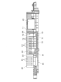
- FIG. 1 is a perspective view of an electrical connection box according to Embodiment 1.
- FIG. 1 is a plan view of an electrical connection box according to Embodiment 1.
- FIG. FIG. 2 is a plan view showing the electrical connection box according to the first embodiment with the upper case removed.
- FIG. 4 is a view taken along arrow IV in FIG. 3; 3 is a sectional view taken along line VV in FIG. 2.
- FIG. 3 is a partial plan view of an electrical connection box according to a second embodiment.
- FIG. 7 is a partial vertical cross-sectional view of an electrical connection box according to Embodiment 3;
- FIG. 7 is a plan view of the electrical connection box of Embodiment 4 with the upper case removed.
- the opening is provided in the housing at a position near the electromagnetic relay, and heat is only radiated to the electromagnetic relay itself, and heat radiation through the bus bar is not devised. Therefore, it is difficult to say that the heat from the electromagnetic relay is dissipated efficiently.
- An electrical junction box includes a housing that has a fixed wall that is fixed to an object and is provided with an electronic component, and a housing that is arranged to face the fixed wall and is connected to the electronic component.
- the electrical connection box is provided with a board-shaped bus bar, and is provided with a plurality of heat radiating plates that are erected in a direction intersecting with the bus bar and radiate heat from the bus bar.
- the heat generated in the electronic component during energization and transmitted to the bus bar can be quickly radiated, and the heat can be radiated from the electronic component more effectively.
- the electrical junction box according to the embodiment of the present disclosure includes a base plate whose first main surface is in contact with one main surface of the bus bar, and the plurality of heat sinks are provided on the second main surface of the base plate. It is being
- heat generated in the electronic component when energized is transmitted to the bus bar, and is conducted to the plurality of heat sinks via the base plate, and the plurality of heat sinks quickly radiate the heat. . Therefore, heat can be effectively radiated from the electronic component.
- a first through hole is formed in a facing wall facing the fixed wall, and the first through hole is formed in a facing wall opposite to the fixed wall and the facing wall. It is formed at a position corresponding to the gap between adjacent heat sinks in the direction.
- the first through hole is formed at a position corresponding to a gap between adjacent heat sinks in the opposing direction. Therefore, the outside air flowing into the housing from the first through hole quickly flows into the gap between the heat sinks, air-cools the heat sinks, and fills the gap between the heat sinks containing the radiated heat. The air rises and quickly flows out of the housing through the first through hole. Therefore, heat can be effectively radiated from the electronic component.
- the first through hole extends along the heat sink.
- the size of the first through hole can be adjusted at a portion of the opposing wall corresponding to the gap between adjacent heat sinks. can be effectively ensured.
- side walls extending toward the fixed wall are connected to both opposing edges of the opposing wall, and a second through hole is formed in each side wall.
- the second through-holes are formed in opposing directions of the two side walls at positions corresponding to gaps between adjacent heat sinks.
- the second through holes are formed in positions corresponding to the gaps between adjacent heat sinks in the opposing direction of the two side walls, the second through holes of the one side wall Air flowing in through the through holes passes between adjacent heat sinks, and quickly flows out from the second through hole in the other side wall. At this time, since the heat convected from the heat sink also flows to the outside of the housing, the cooling effect of the electronic components can be further enhanced.
- the second through hole extends along the heat sink.
- the second through hole extends along the heat sink, the second through hole extends in a portion of the two side walls that corresponds to the gap between adjacent heat sinks. The size can be effectively secured.
- the base plate and the plurality of heat sinks are integrally formed, and the opposing wall is provided with a positioning part that determines the position of the heat sink. There is.
- the positioning portion is used to determine the position of the heat sink during assembly, so the workability of the assembly work can be improved.
- the heat sink is provided in the vicinity of a connection portion between the bus bar and the electronic component.
- the heat sink is also provided near the connection portion between the bus bar and the electronic component. Therefore, it is possible to more efficiently cool down the connection portion, which generates heat intensively when energized.
- the number of heat sinks is greater in the vicinity of the connection portion than in other parts.
- the number of heat sinks near the connection portion between the bus bar and the electronic component is greater than in other parts. Therefore, it is possible to more efficiently cool down the connection portion, which generates heat intensively when energized.
- the electrical connection box according to the embodiment of the present disclosure includes a plurality of first through holes, and one of the plurality of first through holes is formed near a connecting portion between the bus bar and the electronic component. One of the first through holes is larger than the other first through holes.
- the size of one first through hole formed near the connection portion is larger than the other first through holes. Therefore, the inflow of outside air into the connection part and the outflow of air containing heat radiated from the connection part are increased, and the heat generated in the connection part when electricity is applied can be cooled more efficiently.
- the electrical connection box according to the embodiment of the present disclosure includes a plurality of second through holes, and one of the plurality of second through holes is formed near a connecting portion between the bus bar and the electronic component. One of the second through holes is larger than the other second through holes.
- the second through hole provided near the connection portion is larger than the other second through holes. Therefore, the inflow of outside air into the connection part and the outflow of air containing heat radiated from the connection part are increased, and the heat generated in the connection part when electricity is applied can be cooled more efficiently.
- FIG. 1 is a perspective view of an electrical junction box 100 according to the first embodiment
- FIG. 2 is a plan view of the electrical junction box 100 according to the first embodiment.
- the positions of a bus bar 10 and a heat radiating member 70, which will be described later, are indicated by broken lines.
- the electrical connection box 100 is attached to the outside of an object to which it is attached, such as a battery pack 200 of an EV (Electric Vehicle), for example.
- FIG. 1 shows a state in which the electrical connection box 100 is attached to the battery pack 200.
- the electrical connection box 100 includes, for example, a housing 50 in which a relay 40 (electronic component), a fuse 60 (electronic component), a board, etc. are housed.
- the housing 50 has a substantially rectangular shape in plan view, and is made of resin, for example.
- the housing 50 includes a lower case 30 that is attached to the mounting target, and an upper case 20 that partially covers the lower case 30.
- Electronic components such as a relay 40, a fuse 60, and a bus bar 10 are attached to the lower case 30, and the upper case 20 covers some of these electronic components.
- the upper case 20 side will be described as the top and the lower case 30 side will be described as the bottom.
- FIG. 3 is a plan view showing the electrical connection box 100 according to the first embodiment with the upper case 20 removed
- FIG. 4 is a view taken along arrow IV in FIG. 3.
- the lower case 30 has a flat box shape with one side open on the upper case 20 side.
- the lower case 30 has a substantially rectangular bottom wall 31 (fixed wall) whose outer side is fixed in contact with the mounting target, and a side wall 33 extending perpendicularly from the edge of the bottom wall 31 toward the upper case 20 side. .
- the relay 40, the fuse 60, and the bus bar 10 are provided inside the lower case 30.
- engagement protrusions 35 that engage with engagement portions 25 of the upper case 20, which will be described later, are protrudingly provided at a plurality of locations on the outer surface of the side wall 33 on the long side of the bottom wall 31. ing.
- the engagement protrusion 35 consists of a pair of protrusions separated from each other in the length direction of the side wall 33.
- fixing holes 37 are formed at the four corners and near the side wall 33 on one long side, which are used when attaching the lower case 30 (casing 50) to a mounting target.
- the lower case 30 is provided with a relay 40 and a fuse 60 separated from each other in the length direction of the lower case 30. That is, the relay 40 is disposed at one end of the lower case 30, and the fuse 60 is disposed at the other end of the lower case 30.
- the fuse 60 is provided near one side wall 33 of the lower case 30 in the width direction. Further, the relay 40 is provided with a connection terminal on the other side wall 33 side in the width direction (see FIG. 4).
- a bus bar 10 is provided between the relay 40 and the fuse 60.
- the bus bar 10 has a substantially plate shape, is made of a conductive metal plate such as copper, and is disposed to face the inner surface of the bottom wall 31 .
- the bus bar 10 has a flat part 13 facing the bottom wall 31, one end part 11 (connection part) screwed to the connection terminal of the relay 40, and the other end part 12 screwed to the connection terminal 61 of the fuse 60. (connection part).
- connection part screwed to the connection terminal of the relay 40
- connection part 12 screwed to the connection terminal 61 of the fuse 60.
- the bus bar 10 has the rectangular plate-shaped other end 12 connected perpendicularly to the flat part 13 at the edge near the fuse 60, and the other end 12 in the flat part 13 near the relay 40.
- One end portion 11 in the shape of a rectangular plate is connected perpendicularly to the flat portion 13 at the edge.
- the one end portion 11 extends in the width direction of the bottom wall 31, and the end portion on the other side wall 33 side is bent along the other side wall 33 and connected to the connection terminal of the relay 40. There is.
- One end 11 and the other end 12 are provided with fixing through holes for screwing.
- oval fixed through holes are formed in the other end 12 and the one end 11, thereby making it possible to accommodate design errors and tolerances.
- the bus bar 10 is provided such that one main surface of the flat portion 13 faces the bottom wall 31.
- a heat radiating member 70 is screwed to the flat portion 13 of the bus bar 10 to radiate heat generated by the bus bar 10 when energized.
- a heat radiating member 70 is provided over most of the flat portion 13, including the vicinity of the one end 11 and the other end 12.
- the heat dissipation member 70 has a comb shape in a longitudinal cross-sectional view extending in the length direction of the lower case 30, and includes a base plate 71 and a plurality of heat dissipation fins 72 (heat dissipation plates).
- the base plate 71 is made of a material with good thermal conductivity, such as aluminum, and has a substantially rectangular shape.
- One principal surface (first principal surface) of the base plate 71 is in contact with the other principal surface of the flat portion 13 of the bus bar 10 .
- a plurality of radiation fins 72 are provided on the other main surface (second main surface) of the base plate 71 .
- Each radiation fin 72 has a rectangular plate shape and is made of the same material as the base plate 71.
- the radiation fins 72 and the base plate 71 are integrally formed.
- the heat dissipation fins 72 are erected substantially perpendicularly from the base plate 71.
- the radiation fins 72 are arranged in parallel at predetermined intervals in the longitudinal direction of the bottom wall 31 .
- the upper case 20 has a box shape with one side open on the lower case 30 side.
- the upper case 20 is slightly smaller than the lower case 30 in a length direction and a width direction perpendicular to the length direction.
- the upper case 20 has a ceiling wall 21 facing the bottom wall 31 of the lower case 30, and a side wall 22 that is provided around the edge of the ceiling wall 21 and extends toward the lower case 30 (see FIG. 1). .
- a plurality of through holes 23 are formed in the ceiling wall 21. More specifically, a plurality of through holes 23 are formed in most of the ceiling wall 21 including the vicinity of the bus bar 10 . A plurality of through holes 23 are formed along the ceiling wall 21.
- the through holes 23 provided near the bus bar 10 are adjacent to each other in the opposing direction between the ceiling wall 21 and the bottom wall 31 of the lower case 30 (hereinafter simply referred to as the opposing direction). It is formed at a position corresponding to the gap between the matching heat radiation fins 72 (see FIG. 2). In other words, the area directly below each through hole 23 corresponds to the space between adjacent radiation fins 72 . Further, each through hole 23 has a substantially rectangular shape extending along the radiation fin 72. In particular, the through hole 23 provided near the bus bar 10 extends along the gap between adjacent radiation fins 72 .
- FIG. 5 is a sectional view taken along line VV in FIG. 2. Furthermore, a positioning portion 28 is provided protruding from the inner surface of the ceiling wall 21 to determine the position of the heat radiating member 70 (radiating fin 72) during assembly work. Positioning portions 28 are provided near the radiation fins 72 at both ends in the direction in which the radiation fins 72 are arranged side by side. Specifically, in the opposing direction, the position corresponding to the gap between the radiation fin 72 at one end and the adjacent radiation fin 72 among the radiation fins 72 at both ends, or the radiation fin 72 at the other end and the radiation adjacent thereto. A positioning portion 28 is provided at a position corresponding to the gap between the fins 72. Each positioning portion 28 has a rectangular shape when viewed in longitudinal section, and the position of the heat radiating member 70 is determined by the tip portion coming into contact with the inner surface of the heat radiating fin 72 at the end.
- a plurality of side wall through holes 24 are formed in the two side walls 22 facing each other in the width direction of the ceiling wall 21, extending to the edge of the ceiling wall 21. That is, a plurality of side wall through holes 24 are formed in one side wall 22 facing the fuse 60 and the other side wall 22 facing the connection terminal of the relay 40.
- the side wall through holes 24 are particularly formed in a concentrated manner near the bus bar 10, that is, near the through holes 23.
- the side wall through holes 24 are formed at regular intervals in the length direction of the upper case 20.
- the side wall through holes 24 of the one side wall 22 and the side wall through holes 24 of the other side wall 22 are formed in the width direction of the ceiling wall 21 (that is, in the opposing direction of the one side wall 22 and the other side wall 22). ) are formed at mutually aligned positions. Further, the side wall through holes 24 of the one side wall 22 and the side wall through holes 24 of the other side wall 22 are formed at positions corresponding to gaps between adjacent radiation fins 72 in the width direction of the ceiling wall 21. (See Figures 2 and 5).
- the radiation fins 72 are not located between the side wall through holes 24 of the one side wall 22 and the side wall through holes 24 of the other side wall 22, which correspond in the width direction of the ceiling wall 21. A gap is formed between the heat radiation fins 72 that fit together.
- the side wall through hole 24 of the one side wall 22 and the side wall through hole 24 of the other side wall 22 have a substantially rectangular shape extending along the opposing direction.
- the side wall through hole 24 provided near the bus bar 10 extends along the gap between adjacent radiation fins 72 .
- each through hole 23 and each side wall through hole 24 of the upper case 20 has a width of several mm, for example, so that a fingertip of a person handling it cannot fit therein.
- the side wall 22 is provided with engaging portions 25 that engage with the engaging protrusions 35 of the lower case 30 at multiple locations on the lower end.
- the engaging portion 25 has a U-shape, both open end portions are fixed to the side wall 22, and the curved portion projects downward from the side wall 22.
- a current in the range of 300A to 1000A is used.
- heat is generated from the relay 40 and fuse 60, and the heat from the relay 40 and fuse 60 is immediately transferred to the bus bar 10 that is in direct contact with it.
- the heat emitted from the relay 40 and the fuse 60 may have a negative effect on the electronic components around the relay 40, the fuse 60, and the bus bar 10, so it is necessary to cool them down quickly.
- the heat dissipation effect of heat dissipation from the relay 40 and fuse 60 itself cannot be expected to be large, and heat dissipation via the bus bar 10 connected to the relay 40 and fuse 60 is more efficient.
- the heat radiating member 70 is provided on the bus bar 10.
- the heat transferred from the relay 40 and fuse 60 to the bus bar 10 and the heat generated in the bus bar 10 are quickly transferred to the base plate 71 of the heat dissipation member 70 that is in direct contact with the bus bar 10 and are dissipated into the air via the heat dissipation fins 72.
- Heat is radiated to Therefore, the heat generated from the relay 40 and the fuse 60 can be efficiently dissipated via the bus bar 10, and the heat generated at the bus bar 10 can also be appropriately dissipated, so that the above-mentioned problems can be prevented in advance.
- a large current for example, 1000 A
- a large current cannot be used for a long time due to safety issues and the problem that a large amount of heat is generated in the bus bar 10, and is used intermittently for short periods of time.
- the time for the large current to flow is short, so rather than generating heat in the entire bus bar 10, heat is generated at the connection part with the relay 40 and fuse 60, that is, at both ends 11 and 12 of the bus bar 10. A concentrated fever occurs.
- heat radiating members 70 are also provided near one end 11 and the other end 12 of the bus bar 10. Therefore, as described above, even when a large current flows and heat is concentrated at both ends 11 and 12 of the bus bar 10, the heat from the bus bar 10, the relay 40, and the fuse 60 can be effectively radiated.
- the through hole 23 and the side wall through hole 24 are formed in the upper case 20 near the bus bar 10, as described above. Therefore, air can easily flow into the bus bar 10 and the heat radiating member 70 from the outside, and the air cooling effect can be enhanced.
- the through hole 23 of the upper case 20 is located at a position corresponding to the gap between the adjacent radiation fins 72 in the direction in which the ceiling wall 21 and the bottom wall 31 face each other. is formed. Further, the side wall through hole 24 of the upper case 20 is formed at a position corresponding to the gap between adjacent radiation fins 72 in the width direction of the ceiling wall 21. Therefore, external air flows into the space between the adjacent radiation fins 72 and internal air flows out from between the adjacent radiation fins 72 without stagnation.
- the side wall through hole 24 of the one side wall 22 and the side wall through hole 24 of the other side wall 22 are formed at positions aligned with each other in the width direction of the ceiling wall 21, A gap between adjacent radiation fins 72 is formed between the side wall through hole 24 of the side wall 22 on one side and the side wall through hole 24 of the side wall 22 on the other side.
- the through hole 23 provided near the bus bar 10 is formed at a position corresponding to the gap between the adjacent radiation fins 72 in the opposing direction between the ceiling wall 21 and the bottom wall 31 of the lower case 30. has been done. Therefore, when air containing heat convected from the radiation fins 72 rises from between the adjacent radiation fins 72, it quickly flows to the outside of the housing 50 through the through hole 23 directly above. Therefore, the effect of cooling the relay 40, fuse 60, and bus bar 10 can be further enhanced.
- FIG. 6 is a partial plan view of the electrical connection box 100 according to the second embodiment.
- the vicinity of the bus bar 10 is shown in an enlarged manner, and the positions of the bus bar 10 and the heat radiating member 70 are shown with broken lines.
- a plurality of through holes 23 are formed in the vicinity of the bus bar 10 in the ceiling wall 21 of the upper case 20, and a plurality of through holes 23 (first through holes) are formed in the vicinity of the bus bar 10 in the ceiling wall 21 of the upper case 20.
- a plurality of side wall through holes 24 are formed near the.
- the through hole 23 provided near the bus bar 10 is formed at a position corresponding to the gap between adjacent radiation fins 72 in the opposing direction between the ceiling wall 21 and the bottom wall 31, as in the first embodiment. That is, the area directly below each through hole 23 corresponds to the space between adjacent radiation fins 72 .
- Each through hole 23 extends along the radiation fin 72 and has a substantially rectangular shape.
- the through holes 23A formed near one end 11 and the other end 12 of the bus bar 10 are larger than the other through holes 23. It is formed.
- the size of the through hole 23A in the direction in which the plurality of through holes 23 are lined up is larger than the other through holes 23.
- the through hole 23A formed near the one end 11 and the other end 12 of the bus bar 10 is different from the other through hole 23. larger than Therefore, the amount of air flowing in from the through hole 23A becomes relatively large, and thereby the one end 11 and the other end 12 can be cooled more intensively, and a large current flows to both ends of the bus bar 10. 11 and 12 can handle cases where heat generation is concentrated.
- Embodiment 1 The same parts as in Embodiment 1 are given the same reference numerals and detailed explanations are omitted.
- FIG. 7 is a partial vertical cross-sectional view of the electrical connection box 100 according to the third embodiment.
- the vicinity of the heat radiating member 70 is shown in an enlarged manner, and the position of the other end portion 12 is shown with a chain line.
- a plurality of through holes 23 are formed in the vicinity of the bus bar 10 in the ceiling wall 21 of the upper case 20, and a plurality of through holes 23 (first through holes) are formed in the vicinity of the bus bar 10 in the ceiling wall 21 of the upper case 20.
- a plurality of side wall through holes 24 are formed near the.
- the upper case 20 has a plurality of side wall through holes 24 (second through holes) in the one side wall 22 and the other side wall 22 that are opposite to each other in the width direction of the ceiling wall 21. are formed respectively.
- the side wall through holes 24 are particularly formed in a concentrated manner near the bus bar 10, that is, near the through holes 23.
- the side wall through holes 24 of the one side wall 22 and the side wall through holes 24 of the other side wall 22 are formed at positions that align with each other in the width direction of the ceiling wall 21.
- the side wall through holes 24 and the side wall through holes 24 of the other side wall 22 are formed at positions corresponding to the gaps between adjacent radiation fins 72 in the width direction of the ceiling wall 21 (see FIGS. 2 and 7). ).
- Each side wall through hole 24 extends along the gap between adjacent radiation fins 72 and has a substantially rectangular shape.
- the side wall through holes 24A formed near one end 11 and the other end 12 of the bus bar 10 are , is formed larger than the other side wall through holes 24.
- FIG. 7 only the side wall 22 on the other side is shown, but in both the side wall through hole 24 of the side wall 22 on the one side and the side wall through hole 24 of the side wall 22 on the other side, both ends 11 and 12 are A side wall through hole 24A larger than the other side wall through holes 24 is formed nearby.
- the size of the side wall through hole 24A in the direction in which the plurality of side wall through holes 24 are lined up is larger than other side wall through holes 24, or the ratio of the side wall through hole to the gap between adjacent radiation fins 72 is different from that of the side wall through hole 24A. It is larger than the side wall through hole 24 of.
- the other through-holes 23 are the same as those in the first embodiment, and detailed description thereof will be omitted.
- the side wall through hole 24A formed near the one end 11 and the other end 12 of the bus bar 10 is connected to the other side wall. It is larger than the through hole 24. Therefore, the amount of air flowing in from the side wall through hole 24A becomes relatively large, and thereby the one end 11 and the other end 12 can be cooled more intensively, and a large current flows to both ends of the bus bar 10. This can deal with cases where heat generation is concentrated in the parts 11 and 12.
- Embodiment 1 The same parts as in Embodiment 1 are given the same reference numerals and detailed explanations are omitted.
- FIG. 8 is a plan view of the electrical junction box 100 of the fourth embodiment with the upper case 20 removed. In FIG. 8, the vicinity of the heat radiating member 70 is shown in an enlarged manner for convenience.
- the electrical junction box 100 of the fourth embodiment includes a bus bar 10 as in the first embodiment, and the flat part 13 of the bus bar 10 is arranged to face the bottom wall 31, and the flat part 13 has a part where the bus bar 10 emits when electricity is applied.
- a heat radiating member 70 that radiates heat is attached.
- the heat dissipation member 70 has a comb shape in a longitudinal cross-sectional view extending in the length direction of the lower case 30, and includes a base plate 71 and a plurality of heat dissipation fins 72 (heat dissipation plates).
- the base plate 71 is made of a material with good thermal conductivity, such as aluminum, and has a rectangular shape. One main surface of the base plate 71 is in contact with the other main surface of the flat portion 13 of the bus bar 10, and a plurality of heat radiation fins 72 are provided on the other main surface.
- Each radiation fin 72 has a rectangular plate shape and is made of the same material as the base plate 71.
- the radiation fins 72 and the base plate 71 are integrally formed.
- the heat dissipation fins 72 are erected substantially perpendicularly from the base plate 71.
- the radiation fins 72 are arranged in parallel in the longitudinal direction of the base plate 71.
- the number of radiation fins 72 is greater in the vicinity of the one end 11 and the other end 12 of the bus bar 10 (see the broken line circle in FIG. 8) than in other parts. It is composed of That is, the radiation fins 72 are arranged in a concentrated manner near one end 11 and the other end 12 of the bus bar 10 .
- both end portions 11 and 12 can be cooled more intensively, and it is possible to cope with the case where a large current flows and heat generation is concentrated at both end portions 11 and 12 of bus bar 10.
- Embodiment 1 The same parts as in Embodiment 1 are given the same reference numerals and detailed explanations are omitted.
- Embodiments 1 to 4 can be combined with each other, and new technical features can be formed by combining them.
- the embodiments disclosed herein are illustrative in all respects and should not be considered restrictive.
- the scope of the present invention is indicated by the scope of the claims, not the meaning described above, and is intended to include meanings equivalent to the scope of the claims and all changes within the scope.
Landscapes
- Engineering & Computer Science (AREA)
- Architecture (AREA)
- Civil Engineering (AREA)
- Structural Engineering (AREA)
- Physics & Mathematics (AREA)
- Thermal Sciences (AREA)
- Microelectronics & Electronic Packaging (AREA)
- Connection Or Junction Boxes (AREA)
Abstract
This electrical junction box (100) comprises: a housing (50) that has a fixing wall which is fixed to a target object and that is provided with a relay (40) and a fuse (60); and a bus bar (10) that has a plate shape, that is disposed facing the fixing wall, and that is connected to the relay (40) and the fuse (60). The electrical junction box (100) comprises a plurality of heat radiating plates that are provided upright in an intersecting direction with the bus bar (10) and that discharge heat from the bus bar (10).
Description
本開示は、電気接続箱に関する。
本出願は、2022年9月14日出願の日本出願第2022-146343号に基づく優先権を主張し、前記日本出願に記載された全ての記載内容を援用するものである。 TECHNICAL FIELD This disclosure relates to electrical junction boxes.
This application claims priority based on Japanese Application No. 2022-146343 filed on September 14, 2022, and incorporates all the contents described in the said Japanese application.
従来、多くの車両は、電源と電装品との間に介在させて電力を供給するための電気接続装置を備えている。
Conventionally, many vehicles are equipped with an electrical connection device that is interposed between a power source and electrical components to supply power.
特許文献1には、電磁継電器を収容するハウジングを備える電気接続装置であって、ハウジングにおける電磁継電器の近傍の位置にハウジングの内部の熱を外部に放熱する開口部が設けられた電気接続装置が開示されている。
Patent Document 1 discloses an electrical connection device including a housing that accommodates an electromagnetic relay, and in which the housing is provided with an opening in the vicinity of the electromagnetic relay to radiate heat inside the housing to the outside. Disclosed.
本開示の実施形態に係る電気接続箱は、対象物に固定される固定壁を有し、電子部品が設けられた筐体と、前記固定壁と対向配置され、前記電子部品に接続された板形状のバスバーとを備える電気接続箱であって、前記バスバーとの交差方向に立設されており、前記バスバーの熱を放熱する複数の放熱板を備える。
An electrical connection box according to an embodiment of the present disclosure includes a housing having a fixed wall fixed to an object and provided with electronic components, and a board arranged opposite to the fixed wall and connected to the electronic component. The electrical connection box is provided with a shaped bus bar, and is provided with a plurality of heat radiating plates that are erected in a direction intersecting the bus bar and radiate heat from the bus bar.
[本開示が解決しようとする課題]
例えば、リレー等、通電時に発熱する電子部品の場合、事実上、電子部品自体に対する放熱による放熱効果は大きく期待できず、斯かる電子部品と接続され、かつ空気中にさらされているバスバーを介した放熱がより効率的である。 [Problems that this disclosure seeks to solve]
For example, in the case of electronic components such as relays that generate heat when energized, it is virtually impossible to expect a large heat dissipation effect from heat dissipation from the electronic component itself, and it is possible to dissipate heat through the bus bar connected to the electronic component and exposed to the air. heat dissipation is more efficient.
しかしながら、特許文献1の電気接続装置は、開口部が、ハウジングにおいて電磁継電器の近傍の位置に設けられており、電磁継電器自体に対する放熱が行われるのみであってバスバーを介した放熱は工夫されておらず、電磁継電器の熱を効率的に放熱しているとは言いにくい。
However, in the electrical connection device of Patent Document 1, the opening is provided in the housing at a position near the electromagnetic relay, and heat is only radiated to the electromagnetic relay itself, and heat radiation through the bus bar is not devised. Therefore, it is difficult to say that the heat from the electromagnetic relay is dissipated efficiently.
そこで、通電時に発熱する電子部品の熱をより効果的に放熱できる電気接続箱を提供することを目的とする。
Therefore, it is an object of the present invention to provide an electrical connection box that can more effectively radiate heat from electronic components that generate heat when energized.
[本開示の効果]
本開示によれば、通電時に発熱する電子部品の熱をより効果的に放熱できる。 [Effects of this disclosure]
According to the present disclosure, it is possible to more effectively radiate heat from electronic components that generate heat when energized.
本開示によれば、通電時に発熱する電子部品の熱をより効果的に放熱できる。 [Effects of this disclosure]
According to the present disclosure, it is possible to more effectively radiate heat from electronic components that generate heat when energized.
[本発明の実施形態の説明]
最初に本開示の実施態様を列挙して説明する。また、以下に記載する実施形態の少なくとも一部を任意に組み合わせてもよい。 [Description of embodiments of the present invention]
First, embodiments of the present disclosure will be listed and described. Furthermore, at least some of the embodiments described below may be combined arbitrarily.
最初に本開示の実施態様を列挙して説明する。また、以下に記載する実施形態の少なくとも一部を任意に組み合わせてもよい。 [Description of embodiments of the present invention]
First, embodiments of the present disclosure will be listed and described. Furthermore, at least some of the embodiments described below may be combined arbitrarily.
(1)本開示の実施形態に係る電気接続箱は、対象物に固定される固定壁を有し、電子部品が設けられた筐体と、前記固定壁と対向配置され、前記電子部品に接続された板形状のバスバーとを備える電気接続箱であって、前記バスバーとの交差方向に立設されており、前記バスバーの熱を放熱する複数の放熱板を備える。
(1) An electrical junction box according to an embodiment of the present disclosure includes a housing that has a fixed wall that is fixed to an object and is provided with an electronic component, and a housing that is arranged to face the fixed wall and is connected to the electronic component. The electrical connection box is provided with a board-shaped bus bar, and is provided with a plurality of heat radiating plates that are erected in a direction intersecting with the bus bar and radiate heat from the bus bar.
本実施形態にあっては、前記複数の放熱板を備えるので、通電時に前記電子部品で発生し、前記バスバーに伝わる熱を速やかに放熱でき、より効果的に前記電子部品を放熱できる。
In this embodiment, since the plurality of heat radiating plates are provided, the heat generated in the electronic component during energization and transmitted to the bus bar can be quickly radiated, and the heat can be radiated from the electronic component more effectively.
(2)本開示の実施形態に係る電気接続箱は、第1主面が前記バスバーの一主面と接する基部板を備え、前記複数の放熱板は、前記基部板の第2主面に設けられている。
(2) The electrical junction box according to the embodiment of the present disclosure includes a base plate whose first main surface is in contact with one main surface of the bus bar, and the plurality of heat sinks are provided on the second main surface of the base plate. It is being
本実施形態にあっては、通電時に前記電子部品で発生する熱が前記バスバーに伝わり、前記基部板を介して前記複数の放熱板に伝導され、前記複数の放熱板が熱を速やかに放熱する。よって、効果的に前記電子部品を放熱できる。
In this embodiment, heat generated in the electronic component when energized is transmitted to the bus bar, and is conducted to the plurality of heat sinks via the base plate, and the plurality of heat sinks quickly radiate the heat. . Therefore, heat can be effectively radiated from the electronic component.
(3)本開示の実施形態に係る電気接続箱は、前記固定壁と対向する対向壁に第1貫通孔が形成されており、前記第1貫通孔は、前記固定壁及び前記対向壁の対向方向にて、隣り合う放熱板間の間隙に対応する位置に形成されている。
(3) In the electrical connection box according to the embodiment of the present disclosure, a first through hole is formed in a facing wall facing the fixed wall, and the first through hole is formed in a facing wall opposite to the fixed wall and the facing wall. It is formed at a position corresponding to the gap between adjacent heat sinks in the direction.
本実施形態にあっては、前記対向方向にて隣り合う放熱板間の間隙に対応する位置に前記第1貫通孔が形成されている。従って、前記第1貫通孔から前記筐体内に流入される外気は速やかに前記放熱板間の間隙に流れ行き、放熱板を空冷させ、かつ、放熱された熱を含む前記放熱板間の間隙の空気は、上昇して、前記第1貫通孔を介して速やかに筐体の外側に流出される。よって、効果的に前記電子部品を放熱できる。
In this embodiment, the first through hole is formed at a position corresponding to a gap between adjacent heat sinks in the opposing direction. Therefore, the outside air flowing into the housing from the first through hole quickly flows into the gap between the heat sinks, air-cools the heat sinks, and fills the gap between the heat sinks containing the radiated heat. The air rises and quickly flows out of the housing through the first through hole. Therefore, heat can be effectively radiated from the electronic component.
(4)本開示の実施形態に係る電気接続箱は、前記第1貫通孔は前記放熱板に沿って延びている。
(4) In the electrical connection box according to the embodiment of the present disclosure, the first through hole extends along the heat sink.
本実施形態にあっては、前記第1貫通孔が前記放熱板に沿って延びているので、前記対向壁における隣り合う放熱板間の間隙に対応する部分にて、前記第1貫通孔の大きさを有効に確保できる。
In the present embodiment, since the first through hole extends along the heat sink, the size of the first through hole can be adjusted at a portion of the opposing wall corresponding to the gap between adjacent heat sinks. can be effectively ensured.
(5)本開示の実施形態に係る電気接続箱は、前記対向壁の対向する両辺縁には、前記固定壁側に延びる側壁が夫々連設され、各側壁に第2貫通孔が形成されており、前記第2貫通孔は、2つの前記側壁の対向方向にて、隣り合う放熱板間の間隙に対応する位置に夫々形成されている。
(5) In the electrical junction box according to the embodiment of the present disclosure, side walls extending toward the fixed wall are connected to both opposing edges of the opposing wall, and a second through hole is formed in each side wall. The second through-holes are formed in opposing directions of the two side walls at positions corresponding to gaps between adjacent heat sinks.
本実施形態にあっては、前記2つの側壁の対向方向にて、隣り合う放熱板間の間隙に対応する位置に前記第2貫通孔が夫々形成されているので、一側の側壁の第2貫通孔から流れ込んだ空気が隣り合う放熱板の間を通り、他側の側壁の第2貫通孔から速やかに流れ出す。この際、放熱板から対流した熱も筐体の外側に流れるので、前記電子部品の冷却効果を更に高めることが出来る。
In this embodiment, since the second through holes are formed in positions corresponding to the gaps between adjacent heat sinks in the opposing direction of the two side walls, the second through holes of the one side wall Air flowing in through the through holes passes between adjacent heat sinks, and quickly flows out from the second through hole in the other side wall. At this time, since the heat convected from the heat sink also flows to the outside of the housing, the cooling effect of the electronic components can be further enhanced.
(6)本開示の実施形態に係る電気接続箱は、前記第2貫通孔は前記放熱板に沿って延びている。
(6) In the electrical connection box according to the embodiment of the present disclosure, the second through hole extends along the heat sink.
本実施形態にあっては、前記第2貫通孔が前記放熱板に沿って延びているので、前記2つの側壁における隣り合う放熱板間の間隙に対応する部分にて、前記第2貫通孔の大きさを有効に確保できる。
In the present embodiment, since the second through hole extends along the heat sink, the second through hole extends in a portion of the two side walls that corresponds to the gap between adjacent heat sinks. The size can be effectively secured.
(7)本開示の実施形態に係る電気接続箱は、前記基部板及び前記複数の放熱板は一体形成されており、前記対向壁には、前記放熱板の位置を定める位置決め部が設けられている。
(7) In the electrical junction box according to the embodiment of the present disclosure, the base plate and the plurality of heat sinks are integrally formed, and the opposing wall is provided with a positioning part that determines the position of the heat sink. There is.
本実施形態にあっては、組み立ての際に、前記放熱板の位置の定めに前記位置決め部が用いられるので、組み立て作業の作業性を高めることができる。
In this embodiment, the positioning portion is used to determine the position of the heat sink during assembly, so the workability of the assembly work can be improved.
(8)本開示の実施形態に係る電気接続箱は、前記バスバーと前記電子部品との接続部の近傍に、前記放熱板が設けられている。
(8) In the electrical connection box according to the embodiment of the present disclosure, the heat sink is provided in the vicinity of a connection portion between the bus bar and the electronic component.
本実施形態にあっては、前記放熱板が、前記バスバーと前記電子部品との接続部の近傍にも設けられている。従って、通電時に発熱が集中的に行われる、前記接続部をより効率的に冷却させることができる。
In this embodiment, the heat sink is also provided near the connection portion between the bus bar and the electronic component. Therefore, it is possible to more efficiently cool down the connection portion, which generates heat intensively when energized.
(9)本開示の実施形態に係る電気接続箱は、前記接続部の近傍では、前記放熱板の数が、他部分よりも多い。
(9) In the electrical connection box according to the embodiment of the present disclosure, the number of heat sinks is greater in the vicinity of the connection portion than in other parts.
本実施形態にあっては、前記バスバーと前記電子部品との接続部の近傍での前記放熱板の数が他部分よりも多い。従って、通電時に発熱が集中的に行われる、前記接続部をより効率的に冷却させることができる。
In this embodiment, the number of heat sinks near the connection portion between the bus bar and the electronic component is greater than in other parts. Therefore, it is possible to more efficiently cool down the connection portion, which generates heat intensively when energized.
(10)本開示の実施形態に係る電気接続箱は、前記第1貫通孔は複数であり、複数の前記第1貫通孔のうち、前記バスバーと前記電子部品との接続部の近傍に形成された一の第1貫通孔は、他の第1貫通孔よりも大きい。
(10) The electrical connection box according to the embodiment of the present disclosure includes a plurality of first through holes, and one of the plurality of first through holes is formed near a connecting portion between the bus bar and the electronic component. One of the first through holes is larger than the other first through holes.
本実施形態にあっては、前記接続部の近傍に形成された一の第1貫通孔の大きさが他の第1貫通孔よりも大きい。従って、前記接続部への外気の流入及び前記接続部から放熱された熱を含む空気の流出が増え、通電時に前記接続部で発生する熱をより効率的に冷却させることができる。
In this embodiment, the size of one first through hole formed near the connection portion is larger than the other first through holes. Therefore, the inflow of outside air into the connection part and the outflow of air containing heat radiated from the connection part are increased, and the heat generated in the connection part when electricity is applied can be cooled more efficiently.
(11)本開示の実施形態に係る電気接続箱は、前記第2貫通孔は複数であり、複数の前記第2貫通孔のうち、前記バスバーと前記電子部品との接続部の近傍に形成された一の第2貫通孔は、他の第2貫通孔よりも大きい。
(11) The electrical connection box according to the embodiment of the present disclosure includes a plurality of second through holes, and one of the plurality of second through holes is formed near a connecting portion between the bus bar and the electronic component. One of the second through holes is larger than the other second through holes.
本実施形態にあっては、前記接続部の近傍に設けられた第2貫通孔は、他の第2貫通孔よりも大きい。従って、前記接続部への外気の流入及び前記接続部から放熱された熱を含む空気の流出が増え、通電時に前記接続部で発生する熱をより効率的に冷却させることができる。
In this embodiment, the second through hole provided near the connection portion is larger than the other second through holes. Therefore, the inflow of outside air into the connection part and the outflow of air containing heat radiated from the connection part are increased, and the heat generated in the connection part when electricity is applied can be cooled more efficiently.
[本発明の実施形態の詳細]
本開示の実施形態に係る電気接続箱を、以下に図面を参照しつつ説明する。なお、本発明はこれらの例示に限定されるものではなく、請求の範囲によって示され、請求の範囲と均等の意味及び範囲内でのすべての変更が含まれることが意図される。 [Details of embodiments of the present invention]
An electrical connection box according to an embodiment of the present disclosure will be described below with reference to the drawings. Note that the present invention is not limited to these examples, but is indicated by the scope of the claims, and is intended to include all changes within the meaning and scope equivalent to the scope of the claims.
(実施形態1)
図1は、実施形態1に係る電気接続箱100の斜視図であり、図2は、実施形態1に係る電気接続箱100の平面図である。図2では、後述するバスバー10及び放熱部材70の位置を破線にて示している。 (Embodiment 1)
FIG. 1 is a perspective view of anelectrical junction box 100 according to the first embodiment, and FIG. 2 is a plan view of the electrical junction box 100 according to the first embodiment. In FIG. 2, the positions of a bus bar 10 and a heat radiating member 70, which will be described later, are indicated by broken lines.
図1は、実施形態1に係る電気接続箱100の斜視図であり、図2は、実施形態1に係る電気接続箱100の平面図である。図2では、後述するバスバー10及び放熱部材70の位置を破線にて示している。 (Embodiment 1)
FIG. 1 is a perspective view of an
電気接続箱100は、例えば、EV(Electric Vehicle)の電池パック200のような装着対象(対象物)の外側に取り付けられる。図1では、便宜上、電気接続箱100が電池パック200に取り付けられた状態を示している。
The electrical connection box 100 is attached to the outside of an object to which it is attached, such as a battery pack 200 of an EV (Electric Vehicle), for example. For convenience, FIG. 1 shows a state in which the electrical connection box 100 is attached to the battery pack 200.
電気接続箱100は、例えば、リレー40(電子部品)、ヒューズ60(電子部品)、基板等が収容された筐体50を備えている。筐体50は、平面視略長方形であって、例えば、樹脂からなる。
The electrical connection box 100 includes, for example, a housing 50 in which a relay 40 (electronic component), a fuse 60 (electronic component), a board, etc. are housed. The housing 50 has a substantially rectangular shape in plan view, and is made of resin, for example.
筐体50は、前記装着対象に取り付けられるロウアーケース30と、ロウアーケース30を部分的に覆うアッパーケース20とを含む。ロウアーケース30には、リレー40、ヒューズ60、バスバー10などの電子部品が取り付けられており、アッパーケース20は、これら電子部品の一部を覆っている。
以下、説明の便宜上、アッパーケース20側を上とし、ロウアーケース30側を下として説明する。 Thehousing 50 includes a lower case 30 that is attached to the mounting target, and an upper case 20 that partially covers the lower case 30. Electronic components such as a relay 40, a fuse 60, and a bus bar 10 are attached to the lower case 30, and the upper case 20 covers some of these electronic components.
Hereinafter, for convenience of explanation, theupper case 20 side will be described as the top and the lower case 30 side will be described as the bottom.
以下、説明の便宜上、アッパーケース20側を上とし、ロウアーケース30側を下として説明する。 The
Hereinafter, for convenience of explanation, the
図3は、実施形態1に係る電気接続箱100において、アッパーケース20を取り外した状態を示す平面図であり、図4は、図3の矢印IVによる矢視図である。
FIG. 3 is a plan view showing the electrical connection box 100 according to the first embodiment with the upper case 20 removed, and FIG. 4 is a view taken along arrow IV in FIG. 3.
ロウアーケース30は、アッパーケース20側の一面が開放された、扁平な箱体の形状をなす。ロウアーケース30は、外側が前記装着対象に接して固定される略長方形の底壁31(固定壁)と、底壁31の縁からアッパーケース20側に垂直に延設された側壁33とを有する。ロウアーケース30の内側には、上述の如く、リレー40、ヒューズ60及びバスバー10が設けられている。
The lower case 30 has a flat box shape with one side open on the upper case 20 side. The lower case 30 has a substantially rectangular bottom wall 31 (fixed wall) whose outer side is fixed in contact with the mounting target, and a side wall 33 extending perpendicularly from the edge of the bottom wall 31 toward the upper case 20 side. . As described above, the relay 40, the fuse 60, and the bus bar 10 are provided inside the lower case 30.
ロウアーケース30の側壁33のうち、底壁31の長辺側の側壁33の外側面には、アッパーケース20の後述する係合部25と係合する係合突起35が複数箇所に突設されている。係合突起35は、側壁33の長さ方向に隔てて設けられた一対の突起からなる。
また、底壁31において、四隅と、一長辺側の側壁33の近傍とには、ロウアーケース30(筐体50)を装着対象に取り付ける際に用いられる固定孔37が形成されている。 Among theside walls 33 of the lower case 30, engagement protrusions 35 that engage with engagement portions 25 of the upper case 20, which will be described later, are protrudingly provided at a plurality of locations on the outer surface of the side wall 33 on the long side of the bottom wall 31. ing. The engagement protrusion 35 consists of a pair of protrusions separated from each other in the length direction of the side wall 33.
Further, in thebottom wall 31, fixing holes 37 are formed at the four corners and near the side wall 33 on one long side, which are used when attaching the lower case 30 (casing 50) to a mounting target.
また、底壁31において、四隅と、一長辺側の側壁33の近傍とには、ロウアーケース30(筐体50)を装着対象に取り付ける際に用いられる固定孔37が形成されている。 Among the
Further, in the
図3及び図4に示すように、ロウアーケース30には、リレー40と、ヒューズ60とが、ロウアーケース30の長さ方向に隔てて設けられている。即ち、ロウアーケース30の一端側には、リレー40が配設されており、ロウアーケース30の他端側には、ヒューズ60が配設されている。ヒューズ60は、ロウアーケース30の幅方向における一側の側壁33の近傍に設けられている。また、リレー40は、前記幅方向における他側の側壁33側に接続端子が設けられている(図4参照)。
As shown in FIGS. 3 and 4, the lower case 30 is provided with a relay 40 and a fuse 60 separated from each other in the length direction of the lower case 30. That is, the relay 40 is disposed at one end of the lower case 30, and the fuse 60 is disposed at the other end of the lower case 30. The fuse 60 is provided near one side wall 33 of the lower case 30 in the width direction. Further, the relay 40 is provided with a connection terminal on the other side wall 33 side in the width direction (see FIG. 4).
リレー40及びヒューズ60の間には、バスバー10が設けられている。バスバー10は略板形状であって、銅等の導電性金属板からなり、底壁31の内面と対向配置されている。バスバー10は、底壁31と対向する扁平部13と、リレー40の前記接続端子にネジ止めされた一端部11(接続部)と、ヒューズ60の接続端子61にネジ止めされた他端部12(接続部)とを含む。以下では、一端部11及び他端部12をあわせて両端部11,12とも言う。
A bus bar 10 is provided between the relay 40 and the fuse 60. The bus bar 10 has a substantially plate shape, is made of a conductive metal plate such as copper, and is disposed to face the inner surface of the bottom wall 31 . The bus bar 10 has a flat part 13 facing the bottom wall 31, one end part 11 (connection part) screwed to the connection terminal of the relay 40, and the other end part 12 screwed to the connection terminal 61 of the fuse 60. (connection part). Hereinafter, the one end portion 11 and the other end portion 12 will also be collectively referred to as both end portions 11 and 12.
即ち、バスバー10は、扁平部13におけるヒューズ60近傍の辺縁に、矩形板形状の他端部12が扁平部13に対して垂直に連設されており、扁平部13におけるリレー40近傍の辺縁に、長方形板形状の一端部11が扁平部13に対して垂直に連設されている。一端部11は、底壁31の幅方向に延びており、前記他側の側壁33側の端部が、前記他側の側壁33に沿って屈曲してリレー40の前記接続端子に接続されている。
That is, the bus bar 10 has the rectangular plate-shaped other end 12 connected perpendicularly to the flat part 13 at the edge near the fuse 60, and the other end 12 in the flat part 13 near the relay 40. One end portion 11 in the shape of a rectangular plate is connected perpendicularly to the flat portion 13 at the edge. The one end portion 11 extends in the width direction of the bottom wall 31, and the end portion on the other side wall 33 side is bent along the other side wall 33 and connected to the connection terminal of the relay 40. There is.
一端部11及び他端部12には、ネジ止めの為の固定貫通孔が形成されている。例えば、他端部12及び一端部11には長円形状の固定貫通孔(図示せず)が形成されており、これによって、設計上の誤差、及び公差に対応できる。
One end 11 and the other end 12 are provided with fixing through holes for screwing. For example, oval fixed through holes (not shown) are formed in the other end 12 and the one end 11, thereby making it possible to accommodate design errors and tolerances.
バスバー10は、扁平部13の一主面が底壁31と対向するように設けられている。バスバー10の扁平部13には、通電時にバスバー10が発する熱を放熱する放熱部材70がネジ止めされている。一端部11近傍及び他端部12近傍を含む、扁平部13の大部分に亘って、放熱部材70が設けられている。
The bus bar 10 is provided such that one main surface of the flat portion 13 faces the bottom wall 31. A heat radiating member 70 is screwed to the flat portion 13 of the bus bar 10 to radiate heat generated by the bus bar 10 when energized. A heat radiating member 70 is provided over most of the flat portion 13, including the vicinity of the one end 11 and the other end 12.
放熱部材70は、ロウアーケース30の長さ方向に延びる縦断面視で櫛形状を成しており、基部板71及び複数の放熱フィン72(放熱板)を含む。
基部板71は、例えばアルミニウムのように、熱伝導性が良い材料からなり、略長方形を有している。基部板71は、一主面(第1主面)が、バスバー10の扁平部13の他主面と接している。基部板71の他主面(第2主面)には、複数の放熱フィン72が設けられている。 Theheat dissipation member 70 has a comb shape in a longitudinal cross-sectional view extending in the length direction of the lower case 30, and includes a base plate 71 and a plurality of heat dissipation fins 72 (heat dissipation plates).
Thebase plate 71 is made of a material with good thermal conductivity, such as aluminum, and has a substantially rectangular shape. One principal surface (first principal surface) of the base plate 71 is in contact with the other principal surface of the flat portion 13 of the bus bar 10 . A plurality of radiation fins 72 are provided on the other main surface (second main surface) of the base plate 71 .
基部板71は、例えばアルミニウムのように、熱伝導性が良い材料からなり、略長方形を有している。基部板71は、一主面(第1主面)が、バスバー10の扁平部13の他主面と接している。基部板71の他主面(第2主面)には、複数の放熱フィン72が設けられている。 The
The
各放熱フィン72は、矩形の板形状であり、基部板71と同じ材料からなる。例えば、放熱フィン72及び基部板71は一体形成されている。放熱フィン72は、基部板71から略垂直に立設されている。放熱フィン72は、底壁31の長手方向に所定間隔で並設されている。
Each radiation fin 72 has a rectangular plate shape and is made of the same material as the base plate 71. For example, the radiation fins 72 and the base plate 71 are integrally formed. The heat dissipation fins 72 are erected substantially perpendicularly from the base plate 71. The radiation fins 72 are arranged in parallel at predetermined intervals in the longitudinal direction of the bottom wall 31 .
アッパーケース20は、ロウアーケース30側の一面が開放された箱体の形状をなす。アッパーケース20は、長さ方向の寸法と、前記長さ方向と直交する幅方向の寸法とがロウアーケース30よりも少し小さい。
The upper case 20 has a box shape with one side open on the lower case 30 side. The upper case 20 is slightly smaller than the lower case 30 in a length direction and a width direction perpendicular to the length direction.
また、アッパーケース20は、ロウアーケース30の底壁31と対向する天井壁21と、天井壁21の縁に周設されており、ロウアーケース30側に延びる側壁22とを有する(図1参照)。
Further, the upper case 20 has a ceiling wall 21 facing the bottom wall 31 of the lower case 30, and a side wall 22 that is provided around the edge of the ceiling wall 21 and extends toward the lower case 30 (see FIG. 1). .
また、アッパーケース20では、天井壁21に、複数の貫通孔23(第1貫通孔)が形成されている。より詳しくは、天井壁21において、バスバー10の近傍を含む大部分に貫通孔23が複数形成されている。複数の貫通孔23は、天井壁21に沿って形成されている。
Furthermore, in the upper case 20, a plurality of through holes 23 (first through holes) are formed in the ceiling wall 21. More specifically, a plurality of through holes 23 are formed in most of the ceiling wall 21 including the vicinity of the bus bar 10 . A plurality of through holes 23 are formed along the ceiling wall 21.
複数の貫通孔23のうち、特に、バスバー10の近傍に設けられた貫通孔23は、天井壁21とロウアーケース30の底壁31との対向方向(以下、単に対向方向と称する)において、隣り合う放熱フィン72間の間隙に対応する位置に形成されている(図2参照)。換言すれば、各貫通孔23の真下は、隣り合う放熱フィン72の間に相当する。また、各貫通孔23は、放熱フィン72に沿って延びている略短冊形状である。特に、バスバー10の近傍に設けられた貫通孔23は、隣り合う放熱フィン72間の間隙に沿って延びている。
Among the plurality of through holes 23, in particular, the through holes 23 provided near the bus bar 10 are adjacent to each other in the opposing direction between the ceiling wall 21 and the bottom wall 31 of the lower case 30 (hereinafter simply referred to as the opposing direction). It is formed at a position corresponding to the gap between the matching heat radiation fins 72 (see FIG. 2). In other words, the area directly below each through hole 23 corresponds to the space between adjacent radiation fins 72 . Further, each through hole 23 has a substantially rectangular shape extending along the radiation fin 72. In particular, the through hole 23 provided near the bus bar 10 extends along the gap between adjacent radiation fins 72 .
図5は、図2のV-V線による断面図である。
また、天井壁21の内側面には、組立作業の際に、放熱部材70(放熱フィン72)の位置を定める位置決め部28が突設されている。放熱フィン72の並設方向における両端の放熱フィン72の近傍に、位置決め部28が夫々設けられている。詳しくは、前記対向方向において、前記両端の放熱フィン72のうち一端の放熱フィン72及びこれと隣り合う放熱フィン72の間隙に相当する位置、又は、他端の放熱フィン72及びこれと隣り合う放熱フィン72の間隙に相当する位置に、位置決め部28が配設されている。各位置決め部28は、縦断面視矩形であり、先端部が前記端の放熱フィン72の内側面と当接することによって、放熱部材70の位置を定めている。 FIG. 5 is a sectional view taken along line VV in FIG. 2.
Furthermore, apositioning portion 28 is provided protruding from the inner surface of the ceiling wall 21 to determine the position of the heat radiating member 70 (radiating fin 72) during assembly work. Positioning portions 28 are provided near the radiation fins 72 at both ends in the direction in which the radiation fins 72 are arranged side by side. Specifically, in the opposing direction, the position corresponding to the gap between the radiation fin 72 at one end and the adjacent radiation fin 72 among the radiation fins 72 at both ends, or the radiation fin 72 at the other end and the radiation adjacent thereto. A positioning portion 28 is provided at a position corresponding to the gap between the fins 72. Each positioning portion 28 has a rectangular shape when viewed in longitudinal section, and the position of the heat radiating member 70 is determined by the tip portion coming into contact with the inner surface of the heat radiating fin 72 at the end.
また、天井壁21の内側面には、組立作業の際に、放熱部材70(放熱フィン72)の位置を定める位置決め部28が突設されている。放熱フィン72の並設方向における両端の放熱フィン72の近傍に、位置決め部28が夫々設けられている。詳しくは、前記対向方向において、前記両端の放熱フィン72のうち一端の放熱フィン72及びこれと隣り合う放熱フィン72の間隙に相当する位置、又は、他端の放熱フィン72及びこれと隣り合う放熱フィン72の間隙に相当する位置に、位置決め部28が配設されている。各位置決め部28は、縦断面視矩形であり、先端部が前記端の放熱フィン72の内側面と当接することによって、放熱部材70の位置を定めている。 FIG. 5 is a sectional view taken along line VV in FIG. 2.
Furthermore, a
また、アッパーケース20において、天井壁21の幅方向に対向する2つの側壁22には、天井壁21の縁部にかけて複数の側壁貫通孔24(第2貫通孔)が形成されている。即ち、ヒューズ60と面する一側の側壁22と、リレー40の前記接続端子と面する他側の側壁22とに側壁貫通孔24が複数形成されている。側壁貫通孔24は、特に、バスバー10の近傍、即ち貫通孔23の近傍に集中的に形成されている。各側壁貫通孔24は、アッパーケース20の長さ方向に一定の間隔で隔てて形成されている。
Furthermore, in the upper case 20, a plurality of side wall through holes 24 (second through holes) are formed in the two side walls 22 facing each other in the width direction of the ceiling wall 21, extending to the edge of the ceiling wall 21. That is, a plurality of side wall through holes 24 are formed in one side wall 22 facing the fuse 60 and the other side wall 22 facing the connection terminal of the relay 40. The side wall through holes 24 are particularly formed in a concentrated manner near the bus bar 10, that is, near the through holes 23. The side wall through holes 24 are formed at regular intervals in the length direction of the upper case 20.
前記一側の側壁22の側壁貫通孔24及び前記他側の側壁22の側壁貫通孔24は、天井壁21の幅方向(即ち、前記一側の側壁22及び前記他側の側壁22の対向方向)において、互いに整合する位置に形成されている。また、前記一側の側壁22の側壁貫通孔24及び前記他側の側壁22の側壁貫通孔24は、天井壁21の幅方向において、隣り合う放熱フィン72間の間隙に対応する位置に形成されている(図2及び図5参照)。
The side wall through holes 24 of the one side wall 22 and the side wall through holes 24 of the other side wall 22 are formed in the width direction of the ceiling wall 21 (that is, in the opposing direction of the one side wall 22 and the other side wall 22). ) are formed at mutually aligned positions. Further, the side wall through holes 24 of the one side wall 22 and the side wall through holes 24 of the other side wall 22 are formed at positions corresponding to gaps between adjacent radiation fins 72 in the width direction of the ceiling wall 21. (See Figures 2 and 5).
従って、天井壁21の幅方向において対応する、前記一側の側壁22の側壁貫通孔24と、前記他側の側壁22の側壁貫通孔24との間に、放熱フィン72が位置せず、隣り合う放熱フィン72の間隙が形成されている。
Therefore, the radiation fins 72 are not located between the side wall through holes 24 of the one side wall 22 and the side wall through holes 24 of the other side wall 22, which correspond in the width direction of the ceiling wall 21. A gap is formed between the heat radiation fins 72 that fit together.
前記一側の側壁22の側壁貫通孔24及び前記他側の側壁22の側壁貫通孔24は、前記対向方向に沿って延びている略短冊形状である。特に、バスバー10の近傍に設けられた側壁貫通孔24は、隣り合う放熱フィン72間の間隙に沿って延びている。
The side wall through hole 24 of the one side wall 22 and the side wall through hole 24 of the other side wall 22 have a substantially rectangular shape extending along the opposing direction. In particular, the side wall through hole 24 provided near the bus bar 10 extends along the gap between adjacent radiation fins 72 .
なお、アッパーケース20の各貫通孔23及び各側壁貫通孔24は、取り扱う人の指先が入らない程度、例えば、数mmの幅を有している。
Note that each through hole 23 and each side wall through hole 24 of the upper case 20 has a width of several mm, for example, so that a fingertip of a person handling it cannot fit therein.
そして、側壁22は、下端部の複数箇所に、ロウアーケース30の係合突起35と係合する係合部25が設けられている。係合部25は、U字形状を成しており、開放側の両端部が側壁22に固定され、湾曲部は、側壁22から下方向に張り出している。アッパーケース20及びロウアーケース30の組立の際には、ロウアーケース30の係合突起35が、係合部25の内側から側壁22の辺縁及び係合部25の湾曲部の間を通ることによって、係合突起35及び係合部25の係合が行われる(図1参照)。
The side wall 22 is provided with engaging portions 25 that engage with the engaging protrusions 35 of the lower case 30 at multiple locations on the lower end. The engaging portion 25 has a U-shape, both open end portions are fixed to the side wall 22, and the curved portion projects downward from the side wall 22. When assembling the upper case 20 and the lower case 30, the engaging protrusion 35 of the lower case 30 passes between the edge of the side wall 22 and the curved part of the engaging part 25 from inside the engaging part 25. , the engagement protrusion 35 and the engagement portion 25 are engaged (see FIG. 1).
電気接続箱100においては、300A~1000Aの範囲の電流が用いられる。電流が流れると、リレー40及びヒューズ60から熱が発生し、リレー40及びヒューズ60の熱は直接的に接しているバスバー10に直ちに伝わる。リレー40及びヒューズ60から発せられる熱は、リレー40、ヒューズ60及びバスバー10周囲の電子部品にも悪い影響を与えるおそれがあることから、速やかに冷却させる必要がある。しかし、リレー40及びヒューズ60自体に対する放熱による放熱効果は大きく期待できず、リレー40及びヒューズ60に接続されたバスバー10を介した放熱がより効率的である。
In the electrical junction box 100, a current in the range of 300A to 1000A is used. When current flows, heat is generated from the relay 40 and fuse 60, and the heat from the relay 40 and fuse 60 is immediately transferred to the bus bar 10 that is in direct contact with it. The heat emitted from the relay 40 and the fuse 60 may have a negative effect on the electronic components around the relay 40, the fuse 60, and the bus bar 10, so it is necessary to cool them down quickly. However, the heat dissipation effect of heat dissipation from the relay 40 and fuse 60 itself cannot be expected to be large, and heat dissipation via the bus bar 10 connected to the relay 40 and fuse 60 is more efficient.
これに対して、本実施形態の電気接続箱100は、バスバー10に放熱部材70が設けられている。通電時に、リレー40及びヒューズ60からバスバー10に伝わる熱及びバスバー10で発生した熱は、バスバー10と直接接している、放熱部材70の基部板71に素早く伝わって放熱フィン72を介して空気中に放熱される。従って、リレー40及びヒューズ60から発する熱をバスバー10を介して効率的に放熱でき、かつバスバー10で発生する熱も適切に放熱できるので、上述したような問題を事前に防止できる。
In contrast, in the electrical connection box 100 of this embodiment, the heat radiating member 70 is provided on the bus bar 10. When energized, the heat transferred from the relay 40 and fuse 60 to the bus bar 10 and the heat generated in the bus bar 10 are quickly transferred to the base plate 71 of the heat dissipation member 70 that is in direct contact with the bus bar 10 and are dissipated into the air via the heat dissipation fins 72. Heat is radiated to Therefore, the heat generated from the relay 40 and the fuse 60 can be efficiently dissipated via the bus bar 10, and the heat generated at the bus bar 10 can also be appropriately dissipated, so that the above-mentioned problems can be prevented in advance.
また、大きい電流(例えば、1000A)は、安全上の問題、及び、バスバー10で多量の熱が発生する問題から、長時間の使用はできず、短時間で間欠的に用いられる。このように、大電流の使用の場合は、大電流が流れる時間が短いので、バスバー10全体で発熱するよりは、リレー40及びヒューズ60との接続部、即ち、バスバー10の両端部11,12で集中して発熱が生じる。
Further, a large current (for example, 1000 A) cannot be used for a long time due to safety issues and the problem that a large amount of heat is generated in the bus bar 10, and is used intermittently for short periods of time. In this way, when using a large current, the time for the large current to flow is short, so rather than generating heat in the entire bus bar 10, heat is generated at the connection part with the relay 40 and fuse 60, that is, at both ends 11 and 12 of the bus bar 10. A concentrated fever occurs.
これに備え、本実施形態の電気接続箱100では、バスバー10の一端部11の近傍及び他端部12の近傍にも放熱部材70(放熱フィン72)が配設されている。よって、上述の如く、大電流が流れてバスバー10の両端部11,12で発熱が集中する場合でも効果的にバスバー10、リレー40及びヒューズ60の熱を放熱できる。
In preparation for this, in the electrical connection box 100 of the present embodiment, heat radiating members 70 (radiating fins 72) are also provided near one end 11 and the other end 12 of the bus bar 10. Therefore, as described above, even when a large current flows and heat is concentrated at both ends 11 and 12 of the bus bar 10, the heat from the bus bar 10, the relay 40, and the fuse 60 can be effectively radiated.
また、本実施形態の電気接続箱100では、上述の如く、アッパーケース20におけるバスバー10の近傍に貫通孔23及び側壁貫通孔24が形成されている。よって、バスバー10及び放熱部材70に外部から空気が流れ込み易く、空冷の効果を高めることが出来る。
Furthermore, in the electrical connection box 100 of this embodiment, the through hole 23 and the side wall through hole 24 are formed in the upper case 20 near the bus bar 10, as described above. Therefore, air can easily flow into the bus bar 10 and the heat radiating member 70 from the outside, and the air cooling effect can be enhanced.
更に、本実施形態の電気接続箱100では、上述の如く、アッパーケース20の貫通孔23が、天井壁21と底壁31との対向方向において、隣り合う放熱フィン72間の間隙に対応する位置に形成されている。また、アッパーケース20の側壁貫通孔24が、天井壁21の幅方向において、隣り合う放熱フィン72間の間隙に対応する位置に形成されている。従って、隣り合う放熱フィン72の間への外部空気の流れ込み、及び、隣り合う放熱フィン72の間からの内部空気の流れ出しが停滞することなく、速やかに行われる。
Furthermore, in the electrical connection box 100 of the present embodiment, as described above, the through hole 23 of the upper case 20 is located at a position corresponding to the gap between the adjacent radiation fins 72 in the direction in which the ceiling wall 21 and the bottom wall 31 face each other. is formed. Further, the side wall through hole 24 of the upper case 20 is formed at a position corresponding to the gap between adjacent radiation fins 72 in the width direction of the ceiling wall 21. Therefore, external air flows into the space between the adjacent radiation fins 72 and internal air flows out from between the adjacent radiation fins 72 without stagnation.
かつ、上述の如く、前記一側の側壁22の側壁貫通孔24及び前記他側の側壁22の側壁貫通孔24は、天井壁21の幅方向において、互いに整合する位置に形成されており、前記一側の側壁22の側壁貫通孔24及び前記他側の側壁22の側壁貫通孔24の間に、隣り合う放熱フィン72間の間隙が形成されている。
Further, as described above, the side wall through hole 24 of the one side wall 22 and the side wall through hole 24 of the other side wall 22 are formed at positions aligned with each other in the width direction of the ceiling wall 21, A gap between adjacent radiation fins 72 is formed between the side wall through hole 24 of the side wall 22 on one side and the side wall through hole 24 of the side wall 22 on the other side.
よって、例えば、前記一側の側壁22の側壁貫通孔24(前記他側の側壁22の側壁貫通孔24)から流れ込んだ空気が隣り合う放熱フィン72の間を通り、前記他側の側壁22の側壁貫通孔24(前記一側の側壁22の側壁貫通孔24)から速やかに流れ出す。この際、放熱フィン72から対流した熱を含む空気が共に筐体50の外側に流れるので、リレー40、ヒューズ60及びバスバー10の冷却の効果を更に高めることが出来る。
Therefore, for example, air flowing from the side wall through hole 24 of the side wall 22 on the one side (the side wall through hole 24 of the side wall 22 on the other side) passes between the adjacent radiation fins 72, and the air flows through the side wall through hole 24 of the side wall 22 on the other side. It quickly flows out from the side wall through hole 24 (the side wall through hole 24 of the one side wall 22). At this time, since the air containing heat convected from the radiation fins 72 flows to the outside of the housing 50, the effect of cooling the relay 40, the fuse 60, and the bus bar 10 can be further enhanced.
そして、上述の如く、バスバー10の近傍に設けられた貫通孔23は、天井壁21とロウアーケース30の底壁31との対向方向において、隣り合う放熱フィン72間の間隙に対応する位置に形成されている。従って、放熱フィン72から対流した熱を含む空気が、隣り合う放熱フィン72の間から上昇する際、速やかに、真上の貫通孔23を介して筐体50の外側に流れる。よって、リレー40、ヒューズ60及びバスバー10の冷却の効果を更に高めることが出来る。
As described above, the through hole 23 provided near the bus bar 10 is formed at a position corresponding to the gap between the adjacent radiation fins 72 in the opposing direction between the ceiling wall 21 and the bottom wall 31 of the lower case 30. has been done. Therefore, when air containing heat convected from the radiation fins 72 rises from between the adjacent radiation fins 72, it quickly flows to the outside of the housing 50 through the through hole 23 directly above. Therefore, the effect of cooling the relay 40, fuse 60, and bus bar 10 can be further enhanced.
(実施形態2)
図6は、実施形態2に係る電気接続箱100の部分的平面図である。図6では、便宜上、バスバー10の近傍を拡大して示しており、バスバー10及び放熱部材70の位置を破線にて示している。 (Embodiment 2)
FIG. 6 is a partial plan view of theelectrical connection box 100 according to the second embodiment. In FIG. 6, for convenience, the vicinity of the bus bar 10 is shown in an enlarged manner, and the positions of the bus bar 10 and the heat radiating member 70 are shown with broken lines.
図6は、実施形態2に係る電気接続箱100の部分的平面図である。図6では、便宜上、バスバー10の近傍を拡大して示しており、バスバー10及び放熱部材70の位置を破線にて示している。 (Embodiment 2)
FIG. 6 is a partial plan view of the
実施形態2の電気接続箱100は、実施形態1と同様、アッパーケース20の天井壁21におけるバスバー10の近傍に、複数の貫通孔23(第1貫通孔)が形成され、側壁22におけるバスバー10の近傍に、複数の側壁貫通孔24(第2貫通孔)が形成されている。
In the electrical junction box 100 of the second embodiment, as in the first embodiment, a plurality of through holes 23 (first through holes) are formed in the vicinity of the bus bar 10 in the ceiling wall 21 of the upper case 20, and a plurality of through holes 23 (first through holes) are formed in the vicinity of the bus bar 10 in the ceiling wall 21 of the upper case 20. A plurality of side wall through holes 24 (second through holes) are formed near the.
バスバー10の近傍に設けられた貫通孔23は、実施形態1と同様、天井壁21と底壁31との対向方向において、隣り合う放熱フィン72間の間隙に対応する位置に形成されている。即ち、各貫通孔23の真下は、隣り合う放熱フィン72の間に相当する。各貫通孔23は、放熱フィン72に沿って延びており、略短冊形状である。
The through hole 23 provided near the bus bar 10 is formed at a position corresponding to the gap between adjacent radiation fins 72 in the opposing direction between the ceiling wall 21 and the bottom wall 31, as in the first embodiment. That is, the area directly below each through hole 23 corresponds to the space between adjacent radiation fins 72 . Each through hole 23 extends along the radiation fin 72 and has a substantially rectangular shape.
実施形態2の電気接続箱100においては、複数の貫通孔23のうち、バスバー10の一端部11及び他端部12の近傍に夫々形成された貫通孔23Aは、他の貫通孔23よりも大きく形成されている。例えば、貫通孔23Aは、前記複数の貫通孔23の並ぶ方向における寸法が、他の貫通孔23よりも大きい。
In the electrical junction box 100 of the second embodiment, among the plurality of through holes 23, the through holes 23A formed near one end 11 and the other end 12 of the bus bar 10 are larger than the other through holes 23. It is formed. For example, the size of the through hole 23A in the direction in which the plurality of through holes 23 are lined up is larger than the other through holes 23.
他、側壁貫通孔24については、実施形態1と同様であり、詳しい説明を省略する。
Other than that, the side wall through hole 24 is the same as in Embodiment 1, and detailed explanation will be omitted.
以上のように、実施形態2の電気接続箱100では、複数の貫通孔23のうち、バスバー10の一端部11及び他端部12の近傍に形成された貫通孔23Aが、他の貫通孔23よりも大きい。従って、貫通孔23Aから流入される空気量が相対的に多くなり、これによって、一端部11及び他端部12をより集中的に冷却させることができ、大電流が流れてバスバー10の両端部11,12で発熱が集中する場合に対応できる。
As described above, in the electrical junction box 100 of the second embodiment, among the plurality of through holes 23, the through hole 23A formed near the one end 11 and the other end 12 of the bus bar 10 is different from the other through hole 23. larger than Therefore, the amount of air flowing in from the through hole 23A becomes relatively large, and thereby the one end 11 and the other end 12 can be cooled more intensively, and a large current flows to both ends of the bus bar 10. 11 and 12 can handle cases where heat generation is concentrated.
実施の形態1と同様の部分については、同一の符号を付して詳細な説明を省略する。
The same parts as in Embodiment 1 are given the same reference numerals and detailed explanations are omitted.
(実施形態3)
図7は、実施形態3に係る電気接続箱100の部分的縦断面図である。図7では、便宜上、放熱部材70の近傍を拡大して示しており、他端部12の位置を一点鎖線にて示している。 (Embodiment 3)
FIG. 7 is a partial vertical cross-sectional view of theelectrical connection box 100 according to the third embodiment. In FIG. 7, for convenience, the vicinity of the heat radiating member 70 is shown in an enlarged manner, and the position of the other end portion 12 is shown with a chain line.
図7は、実施形態3に係る電気接続箱100の部分的縦断面図である。図7では、便宜上、放熱部材70の近傍を拡大して示しており、他端部12の位置を一点鎖線にて示している。 (Embodiment 3)
FIG. 7 is a partial vertical cross-sectional view of the
実施形態3の電気接続箱100は、実施形態1と同様、アッパーケース20の天井壁21におけるバスバー10の近傍に、複数の貫通孔23(第1貫通孔)が形成され、側壁22におけるバスバー10の近傍に、複数の側壁貫通孔24(第2貫通孔)が形成されている。
In the electrical junction box 100 of the third embodiment, as in the first embodiment, a plurality of through holes 23 (first through holes) are formed in the vicinity of the bus bar 10 in the ceiling wall 21 of the upper case 20, and a plurality of through holes 23 (first through holes) are formed in the vicinity of the bus bar 10 in the ceiling wall 21 of the upper case 20. A plurality of side wall through holes 24 (second through holes) are formed near the.
アッパーケース20には、実施形態1と同様、天井壁21の幅方向に対向する、前記一側の側壁22及び前記他側の側壁22に、複数の側壁貫通孔24(第2貫通孔)が夫々形成されている。側壁貫通孔24は、特に、バスバー10の近傍、即ち貫通孔23の近傍に集中的に形成されている。
Similar to Embodiment 1, the upper case 20 has a plurality of side wall through holes 24 (second through holes) in the one side wall 22 and the other side wall 22 that are opposite to each other in the width direction of the ceiling wall 21. are formed respectively. The side wall through holes 24 are particularly formed in a concentrated manner near the bus bar 10, that is, near the through holes 23.
前記一側の側壁22の側壁貫通孔24及び前記他側の側壁22の側壁貫通孔24は、天井壁21の幅方向において、互いに整合する位置に形成されており、前記一側の側壁22の側壁貫通孔24及び前記他側の側壁22の側壁貫通孔24は、天井壁21の幅方向において、隣り合う放熱フィン72間の間隙に対応する位置に形成されている(図2及び図7参照)。各側壁貫通孔24は、隣り合う放熱フィン72間の間隙に沿って延びており、略短冊形状である。
The side wall through holes 24 of the one side wall 22 and the side wall through holes 24 of the other side wall 22 are formed at positions that align with each other in the width direction of the ceiling wall 21. The side wall through holes 24 and the side wall through holes 24 of the other side wall 22 are formed at positions corresponding to the gaps between adjacent radiation fins 72 in the width direction of the ceiling wall 21 (see FIGS. 2 and 7). ). Each side wall through hole 24 extends along the gap between adjacent radiation fins 72 and has a substantially rectangular shape.
実施形態3の電気接続箱100においては、図7に示すように、複数の側壁貫通孔24のうち、バスバー10の一端部11及び他端部12の近傍に夫々形成された側壁貫通孔24Aは、他の側壁貫通孔24よりも大きく形成されている。図7では、他側の側壁22のみを示しているが、前記一側の側壁22の側壁貫通孔24及び前記他側の側壁22の側壁貫通孔24の何れにおいても、両端部11,12の近傍には他の側壁貫通孔24よりも大きい側壁貫通孔24Aが形成されている。
In the electrical junction box 100 of the third embodiment, as shown in FIG. 7, among the plurality of side wall through holes 24, the side wall through holes 24A formed near one end 11 and the other end 12 of the bus bar 10 are , is formed larger than the other side wall through holes 24. In FIG. 7, only the side wall 22 on the other side is shown, but in both the side wall through hole 24 of the side wall 22 on the one side and the side wall through hole 24 of the side wall 22 on the other side, both ends 11 and 12 are A side wall through hole 24A larger than the other side wall through holes 24 is formed nearby.
例えば、側壁貫通孔24Aは、前記複数の側壁貫通孔24の並ぶ方向における寸法が他の側壁貫通孔24よりも大きく、又は、隣り合う放熱フィン72間の間隙に対する側壁貫通孔の比率が、他の側壁貫通孔24よりも大きい。
他、貫通孔23については、実施形態1と同様であり、詳しい説明を省略する。 For example, the size of the side wall throughhole 24A in the direction in which the plurality of side wall through holes 24 are lined up is larger than other side wall through holes 24, or the ratio of the side wall through hole to the gap between adjacent radiation fins 72 is different from that of the side wall through hole 24A. It is larger than the side wall through hole 24 of.
The other through-holes 23 are the same as those in the first embodiment, and detailed description thereof will be omitted.
他、貫通孔23については、実施形態1と同様であり、詳しい説明を省略する。 For example, the size of the side wall through
The other through-
以上のように、実施形態3の電気接続箱100では、複数の側壁貫通孔24のうち、バスバー10の一端部11及び他端部12の近傍に形成された側壁貫通孔24Aが、他の側壁貫通孔24よりも大きい。従って、側壁貫通孔24Aから流入される空気量が相対的に多くなり、これによって、一端部11及び他端部12をより集中的に冷却させることができ、大電流が流れてバスバー10の両端部11,12で発熱が集中する場合に対応できる。
As described above, in the electrical junction box 100 of the third embodiment, among the plurality of side wall through holes 24, the side wall through hole 24A formed near the one end 11 and the other end 12 of the bus bar 10 is connected to the other side wall. It is larger than the through hole 24. Therefore, the amount of air flowing in from the side wall through hole 24A becomes relatively large, and thereby the one end 11 and the other end 12 can be cooled more intensively, and a large current flows to both ends of the bus bar 10. This can deal with cases where heat generation is concentrated in the parts 11 and 12.
実施の形態1と同様の部分については、同一の符号を付して詳細な説明を省略する。
The same parts as in Embodiment 1 are given the same reference numerals and detailed explanations are omitted.
(実施形態4)
図8は、アッパーケース20を取り外し状態における、実施形態4の電気接続箱100の平面図である。図8では、便宜上、放熱部材70の近傍を拡大して示している。 (Embodiment 4)
FIG. 8 is a plan view of theelectrical junction box 100 of the fourth embodiment with the upper case 20 removed. In FIG. 8, the vicinity of the heat radiating member 70 is shown in an enlarged manner for convenience.
図8は、アッパーケース20を取り外し状態における、実施形態4の電気接続箱100の平面図である。図8では、便宜上、放熱部材70の近傍を拡大して示している。 (Embodiment 4)
FIG. 8 is a plan view of the
実施形態4の電気接続箱100は、実施形態1と同様、バスバー10を備えており、バスバー10の扁平部13は底壁31と対向配置され、扁平部13には、通電時にバスバー10が発する熱を放熱する放熱部材70が取り付けられている。放熱部材70は、ロウアーケース30の長さ方向に延びる縦断面視で櫛形状を成しており、基部板71及び複数の放熱フィン72(放熱板)を含む。
The electrical junction box 100 of the fourth embodiment includes a bus bar 10 as in the first embodiment, and the flat part 13 of the bus bar 10 is arranged to face the bottom wall 31, and the flat part 13 has a part where the bus bar 10 emits when electricity is applied. A heat radiating member 70 that radiates heat is attached. The heat dissipation member 70 has a comb shape in a longitudinal cross-sectional view extending in the length direction of the lower case 30, and includes a base plate 71 and a plurality of heat dissipation fins 72 (heat dissipation plates).
基部板71は、例えばアルミニウムのように、熱伝導性が良い材料からなり、矩形を有している。基部板71は、一主面が、バスバー10の扁平部13の他主面と接しており、他主面には、複数の放熱フィン72が設けられている。
The base plate 71 is made of a material with good thermal conductivity, such as aluminum, and has a rectangular shape. One main surface of the base plate 71 is in contact with the other main surface of the flat portion 13 of the bus bar 10, and a plurality of heat radiation fins 72 are provided on the other main surface.
各放熱フィン72は、矩形の板形状であり、基部板71と同じ材料からなる。例えば、放熱フィン72及び基部板71は一体形成されている。放熱フィン72は、基部板71から略垂直に立設されている。放熱フィン72は、基部板71の長手方向に並設されている。
Each radiation fin 72 has a rectangular plate shape and is made of the same material as the base plate 71. For example, the radiation fins 72 and the base plate 71 are integrally formed. The heat dissipation fins 72 are erected substantially perpendicularly from the base plate 71. The radiation fins 72 are arranged in parallel in the longitudinal direction of the base plate 71.
実施形態4の電気接続箱100においては、バスバー10の一端部11及び他端部12の近傍(図8の破線円の部分参照)にて、放熱フィン72の数が他部分よりも多くなるように構成されている。即ち、バスバー10の一端部11及び他端部12の近傍に、放熱フィン72が集中的に配設されている。
In the electrical junction box 100 of the fourth embodiment, the number of radiation fins 72 is greater in the vicinity of the one end 11 and the other end 12 of the bus bar 10 (see the broken line circle in FIG. 8) than in other parts. It is composed of That is, the radiation fins 72 are arranged in a concentrated manner near one end 11 and the other end 12 of the bus bar 10 .
このように、実施形態4の電気接続箱100では、バスバー10の一端部11及び他端部12の近傍に、放熱フィン72が他部分よりも多く配設されていることから、放熱フィン72の数の増加に伴って放熱可能な表面積が増えるので、両端部11,12の近傍で放熱の能力を高めることができる。よって、両端部11,12をより集中的に冷却させることができ、大電流が流れてバスバー10の両端部11,12で発熱が集中する場合に対応できる。
As described above, in the electrical junction box 100 of the fourth embodiment, more radiation fins 72 are disposed near the one end 11 and the other end 12 of the bus bar 10 than in other parts. As the number increases, the surface area that can radiate heat increases, so the heat radiating ability can be enhanced near both ends 11 and 12. Therefore, both end portions 11 and 12 can be cooled more intensively, and it is possible to cope with the case where a large current flows and heat generation is concentrated at both end portions 11 and 12 of bus bar 10.
実施の形態1と同様の部分については、同一の符号を付して詳細な説明を省略する。
The same parts as in Embodiment 1 are given the same reference numerals and detailed explanations are omitted.
実施形態1~4で記載されている技術的特徴(構成要件)はお互いに組み合わせ可能であり、組み合わせすることにより、新しい技術的特徴を形成することができる。
今回開示された実施形態はすべての点で例示であって、制限的なものではないと考えられるべきである。本発明の範囲は、上記した意味ではなく、請求の範囲によって示され、請求の範囲と均等の意味及び範囲内でのすべての変更が含まれることが意図される。 The technical features (constituent features) described in Embodiments 1 to 4 can be combined with each other, and new technical features can be formed by combining them.
The embodiments disclosed herein are illustrative in all respects and should not be considered restrictive. The scope of the present invention is indicated by the scope of the claims, not the meaning described above, and is intended to include meanings equivalent to the scope of the claims and all changes within the scope.
各実施形態に記載した事項は相互に組み合わせることが可能である。また、請求の範囲に記載した独立請求項及び従属請求項は、引用形式に関わらず全てのあらゆる組み合わせにおいて、相互に組み合わせることが可能である。さらに、請求の範囲には他の2以上のクレームを引用するクレームを記載する形式(マルチクレーム形式)を用いているが、これに限るものではない。マルチクレームを少なくとも一つ引用するマルチクレーム(マルチマルチクレーム)を記載する形式を用いて記載しても良い。
The items described in each embodiment can be combined with each other. Moreover, the independent claims and dependent claims recited in the claims may be combined with each other in any and all combinations, regardless of the form in which they are cited. Furthermore, although the scope of claims uses a format in which claims refer to two or more other claims (multi-claim format), the invention is not limited to this format. It may also be written using a multi-claim format that cites at least one multi-claim.
10 バスバー
11 一端部
12 他端部
13 扁平部
20 アッパーケース
21 天井壁
22 側壁
23 貫通孔
24,24A 側壁貫通孔
25 係合部
28 位置決め部
30 ロウアーケース
31 底壁
33 側壁
35 係合突起
37 固定孔
40 リレー
50 筐体
60 ヒューズ
61 接続端子
70 放熱部材
71 基部板
72 放熱フィン
100 電気接続箱
200 電池パック
10Bus bar 11 One end 12 Other end 13 Flat part 20 Upper case 21 Ceiling wall 22 Side wall 23 Through hole 24, 24A Side wall through hole 25 Engagement part 28 Positioning part 30 Lower case 31 Bottom wall 33 Side wall 35 Engagement protrusion 37 Fixation Hole 40 Relay 50 Housing 60 Fuse 61 Connection terminal 70 Heat dissipation member 71 Base plate 72 Heat dissipation fin 100 Electrical connection box 200 Battery pack
11 一端部
12 他端部
13 扁平部
20 アッパーケース
21 天井壁
22 側壁
23 貫通孔
24,24A 側壁貫通孔
25 係合部
28 位置決め部
30 ロウアーケース
31 底壁
33 側壁
35 係合突起
37 固定孔
40 リレー
50 筐体
60 ヒューズ
61 接続端子
70 放熱部材
71 基部板
72 放熱フィン
100 電気接続箱
200 電池パック
10
Claims (11)
- 対象物に固定される固定壁を有し、電子部品が設けられた筐体と、前記固定壁と対向配置され、前記電子部品に接続された板形状のバスバーとを備える電気接続箱であって、
前記バスバーとの交差方向に立設されており、前記バスバーの熱を放熱する複数の放熱板を備える電気接続箱。 An electrical connection box comprising: a housing having a fixed wall fixed to a target object and provided with electronic components; and a plate-shaped bus bar disposed opposite to the fixed wall and connected to the electronic components. ,
An electrical connection box including a plurality of heat radiating plates that are erected in a direction intersecting the bus bar and radiate heat from the bus bar. - 第1主面が前記バスバーの一主面と接する基部板を備え、
前記複数の放熱板は、前記基部板の第2主面に設けられている請求項1に記載の電気接続箱。 comprising a base plate whose first main surface is in contact with one main surface of the bus bar;
The electrical connection box according to claim 1, wherein the plurality of heat sinks are provided on the second main surface of the base plate. - 前記固定壁と対向する対向壁に第1貫通孔が形成されており、
前記第1貫通孔は、前記固定壁及び前記対向壁の対向方向にて、隣り合う放熱板間の間隙に対応する位置に形成されている請求項2に記載の電気接続箱。 A first through hole is formed in a facing wall facing the fixed wall,
The electrical connection box according to claim 2, wherein the first through hole is formed at a position corresponding to a gap between adjacent heat sinks in a direction in which the fixed wall and the opposing wall face each other. - 前記第1貫通孔は前記放熱板に沿って延びている請求項3に記載の電気接続箱。 The electrical connection box according to claim 3, wherein the first through hole extends along the heat sink.
- 前記対向壁の対向する両辺縁には、前記固定壁側に延びる側壁が夫々連設され、
各側壁に第2貫通孔が形成されており、
前記第2貫通孔は、2つの前記側壁の対向方向にて、隣り合う放熱板間の間隙に対応する位置に夫々形成されている請求項3又は4に記載の電気接続箱。 Side walls extending toward the fixed wall are connected to both opposing edges of the opposing wall, and
A second through hole is formed in each side wall,
5. The electrical connection box according to claim 3, wherein the second through holes are formed in opposing directions of the two side walls at positions corresponding to gaps between adjacent heat sinks. - 前記第2貫通孔は前記放熱板に沿って延びている請求項5に記載の電気接続箱。 The electrical connection box according to claim 5, wherein the second through hole extends along the heat sink.
- 前記基部板及び前記複数の放熱板は一体形成されており、
前記対向壁には、前記放熱板の位置を定める位置決め部が設けられている請求項3に記載の電気接続箱。 The base plate and the plurality of heat sinks are integrally formed,
The electrical connection box according to claim 3, wherein the opposing wall is provided with a positioning part for determining the position of the heat sink. - 前記バスバーと前記電子部品との接続部の近傍に、前記放熱板が設けられている請求項1又は2に記載の電気接続箱。 The electrical connection box according to claim 1 or 2, wherein the heat sink is provided near a connection portion between the bus bar and the electronic component.
- 前記接続部の近傍では、前記放熱板の数が、他部分よりも多い請求項8に記載の電気接続箱。 The electrical connection box according to claim 8, wherein the number of the heat sinks is greater in the vicinity of the connection part than in other parts.
- 前記第1貫通孔は複数であり、
複数の前記第1貫通孔のうち、前記バスバーと前記電子部品との接続部の近傍に形成された一の第1貫通孔は、他の第1貫通孔よりも大きい請求項3に記載の電気接続箱。 the first through holes are plural;
4. The electrical appliance according to claim 3, wherein one of the plurality of first through-holes is larger than the other first through-holes formed near the connection portion between the bus bar and the electronic component. connection box. - 前記第2貫通孔は複数であり、
複数の前記第2貫通孔のうち、前記バスバーと前記電子部品との接続部の近傍に形成された一の第2貫通孔は、他の第2貫通孔よりも大きい請求項5に記載の電気接続箱。
the second through holes are plural;
6. The electrical appliance according to claim 5, wherein one of the plurality of second through-holes is larger than the other second through-holes formed near the connection portion between the bus bar and the electronic component. connection box.
Applications Claiming Priority (2)
| Application Number | Priority Date | Filing Date | Title |
|---|---|---|---|
| JP2022146343 | 2022-09-14 | ||
| JP2022-146343 | 2022-09-14 |
Publications (1)
| Publication Number | Publication Date |
|---|---|
| WO2024058186A1 true WO2024058186A1 (en) | 2024-03-21 |
Family
ID=90275109
Family Applications (1)
| Application Number | Title | Priority Date | Filing Date |
|---|---|---|---|
| PCT/JP2023/033258 WO2024058186A1 (en) | 2022-09-14 | 2023-09-12 | Electrical junction box |
Country Status (1)
| Country | Link |
|---|---|
| WO (1) | WO2024058186A1 (en) |
Citations (2)
| Publication number | Priority date | Publication date | Assignee | Title |
|---|---|---|---|---|
| WO2020241310A1 (en) * | 2019-05-28 | 2020-12-03 | 株式会社オートネットワーク技術研究所 | Circuit structure |
| JP2021123112A (en) * | 2020-01-31 | 2021-08-30 | 株式会社デンソー | Vehicular display device |
-
2023
- 2023-09-12 WO PCT/JP2023/033258 patent/WO2024058186A1/en unknown
Patent Citations (2)
| Publication number | Priority date | Publication date | Assignee | Title |
|---|---|---|---|---|
| WO2020241310A1 (en) * | 2019-05-28 | 2020-12-03 | 株式会社オートネットワーク技術研究所 | Circuit structure |
| JP2021123112A (en) * | 2020-01-31 | 2021-08-30 | 株式会社デンソー | Vehicular display device |
Similar Documents
| Publication | Publication Date | Title |
|---|---|---|
| JP6521171B2 (en) | Circuit structure | |
| JP4387314B2 (en) | Electrical junction box | |
| JP6655824B2 (en) | Imaging device | |
| CN110915312B (en) | Circuit structure and electrical connection box | |
| US10880989B2 (en) | Electrical junction box | |
| JPWO2006011478A1 (en) | Electrical junction box | |
| WO2016002748A1 (en) | Electrical junction box | |
| JP2006093404A (en) | Electrical connection box | |
| JP7359300B2 (en) | circuit construct | |
| WO2024058186A1 (en) | Electrical junction box | |
| WO2024058184A1 (en) | Electrical junction box | |
| WO2023037856A1 (en) | Electronic device | |
| WO2022201715A1 (en) | Electronic device housing | |
| JP4524667B2 (en) | Electrical junction box | |
| WO2024058191A1 (en) | Electrical junction box | |
| WO2020080248A1 (en) | Circuit structure and electrical junction box | |
| KR102180032B1 (en) | Motor drive device | |
| JPH11220278A (en) | Heat dissipating structure of heat releasing part | |
| WO2022168649A1 (en) | Electrical junction box | |
| JP6878041B2 (en) | Heat dissipation structure of heat generating parts | |
| JP2006288117A (en) | Switching unit | |
| JP2005294699A (en) | Radiating system | |
| JP2004356292A (en) | Semiconductor device | |
| TWI416059B (en) | Combined cooling device for electric vehicle controller | |
| JP4385922B2 (en) | Electrical junction box |
Legal Events
| Date | Code | Title | Description |
|---|---|---|---|
| 121 | Ep: the epo has been informed by wipo that ep was designated in this application |
Ref document number: 23864129 Country of ref document: EP Kind code of ref document: A1 |