WO2024058016A1 - 電動パワーステアリング装置 - Google Patents
電動パワーステアリング装置 Download PDFInfo
- Publication number
- WO2024058016A1 WO2024058016A1 PCT/JP2023/032444 JP2023032444W WO2024058016A1 WO 2024058016 A1 WO2024058016 A1 WO 2024058016A1 JP 2023032444 W JP2023032444 W JP 2023032444W WO 2024058016 A1 WO2024058016 A1 WO 2024058016A1
- Authority
- WO
- WIPO (PCT)
- Prior art keywords
- housing
- electric power
- holding member
- power steering
- steering device
- Prior art date
- Legal status (The legal status is an assumption and is not a legal conclusion. Google has not performed a legal analysis and makes no representation as to the accuracy of the status listed.)
- Ceased
Links
Images


Classifications
-
- B—PERFORMING OPERATIONS; TRANSPORTING
- B62—LAND VEHICLES FOR TRAVELLING OTHERWISE THAN ON RAILS
- B62D—MOTOR VEHICLES; TRAILERS
- B62D5/00—Power-assisted or power-driven steering
- B62D5/04—Power-assisted or power-driven steering electrical, e.g. using an electric servo-motor connected to, or forming part of, the steering gear
- B62D5/0442—Conversion of rotational into longitudinal movement
- B62D5/0445—Screw drives
- B62D5/0448—Ball nuts
-
- F—MECHANICAL ENGINEERING; LIGHTING; HEATING; WEAPONS; BLASTING
- F16—ENGINEERING ELEMENTS AND UNITS; GENERAL MEASURES FOR PRODUCING AND MAINTAINING EFFECTIVE FUNCTIONING OF MACHINES OR INSTALLATIONS; THERMAL INSULATION IN GENERAL
- F16C—SHAFTS; FLEXIBLE SHAFTS; ELEMENTS OR CRANKSHAFT MECHANISMS; ROTARY BODIES OTHER THAN GEARING ELEMENTS; BEARINGS
- F16C19/00—Bearings with rolling contact, for exclusively rotary movement
- F16C19/02—Bearings with rolling contact, for exclusively rotary movement with bearing balls essentially of the same size in one or more circular rows
- F16C19/04—Bearings with rolling contact, for exclusively rotary movement with bearing balls essentially of the same size in one or more circular rows for radial load mainly
- F16C19/06—Bearings with rolling contact, for exclusively rotary movement with bearing balls essentially of the same size in one or more circular rows for radial load mainly with a single row or balls
-
- F—MECHANICAL ENGINEERING; LIGHTING; HEATING; WEAPONS; BLASTING
- F16—ENGINEERING ELEMENTS AND UNITS; GENERAL MEASURES FOR PRODUCING AND MAINTAINING EFFECTIVE FUNCTIONING OF MACHINES OR INSTALLATIONS; THERMAL INSULATION IN GENERAL
- F16C—SHAFTS; FLEXIBLE SHAFTS; ELEMENTS OR CRANKSHAFT MECHANISMS; ROTARY BODIES OTHER THAN GEARING ELEMENTS; BEARINGS
- F16C35/00—Rigid support of bearing units; Housings, e.g. caps, covers
- F16C35/04—Rigid support of bearing units; Housings, e.g. caps, covers in the case of ball or roller bearings
- F16C35/06—Mounting or dismounting of ball or roller bearings; Fixing them onto shaft or in housing
- F16C35/067—Fixing them in a housing
-
- B—PERFORMING OPERATIONS; TRANSPORTING
- B62—LAND VEHICLES FOR TRAVELLING OTHERWISE THAN ON RAILS
- B62D—MOTOR VEHICLES; TRAILERS
- B62D5/00—Power-assisted or power-driven steering
- B62D5/04—Power-assisted or power-driven steering electrical, e.g. using an electric servo-motor connected to, or forming part of, the steering gear
- B62D5/0403—Power-assisted or power-driven steering electrical, e.g. using an electric servo-motor connected to, or forming part of, the steering gear characterised by constructional features, e.g. common housing for motor and gear box
Definitions
- the present invention relates to an electric power steering device.
- a rotating part (pulley) of a ball screw mechanism is rotatably supported by a housing via a bearing on the outer peripheral side of a rack bar, and the bearing is a lock that is screwed into the housing. It is fastened to the housing via a nut.
- the bearing is fastened to the housing by the lock nut. For this reason, there is a possibility that the lock nut may seize against the housing. Furthermore, if the lock nut is made of a material different from that of the housing, there is a risk that the lock nut may loosen due to thermal effects, so there is still room for improvement.
- the present invention has been devised in view of such technical problems, and provides an electric power steering device that can appropriately and continuously hold a bearing.
- the present invention provides a holding member in which axial movement of a bearing accommodated and supported inside a first housing is regulated by a second housing arranged axially opposite to the first housing. is held by.
- the bearing can be properly and continuously held.
- FIG. 1 is a front view of a steering device according to the present invention.
- FIG. 2 is a cross-sectional view of the vicinity of the transmission mechanism shown in FIG. 1.
- FIG. 3 is an enlarged view of the main part of FIG. 2.
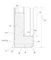
- FIG. 3 is an enlarged view of the holding member shown in FIG. 2.
- FIGS. 1 to 4 illustrate embodiments of the electric power steering device according to the present invention.
- the electric power steering device according to the present invention is applied to a steering device of an automobile, as in the conventional case.
- FIGS. 1 to 4 for convenience, the direction along the central axis X of the rack bar 3 shown in FIG. The direction around the central axis X of the rack bar 3 will be described as the "circumferential direction.”
- FIG. 1 shows a front view of the electric power steering apparatus according to the present embodiment, showing the appearance of the electric power steering apparatus.
- the electric power steering device includes a steering mechanism SM that performs steering based on a driver's operation, and a steering assist mechanism AM that assists the driver's steering operation. Further, the electric power steering device is suspended on the body of the automobile via a bracket BKT attached to the first housing 11 and the second housing 12 that house the steering mechanism SM and the steering assist mechanism AM.
- the steering mechanism SM has a steering shaft 2 linked to a steering wheel (not shown), and a rack bar 3 which is a rack shaft linked to steered wheels (not shown), and the steering shaft 2 and the rack bar 3 are They are linked via a conversion mechanism not shown.
- the conversion mechanism is a so-called rack and pinion mechanism that includes pinion teeth (not shown) formed on the steering shaft 2 (output shaft 22 described later) and rack teeth (not shown) formed on the rack bar 3. .
- the steering shaft 2 is constructed by connecting an input shaft 21 that rotates integrally with a steering wheel (not shown) and an output shaft 22 that is linked to a rack bar 3 by a torsion bar (not shown).
- the input shaft 21 has one axial end (the upper end in FIG. 1) connected to a steering wheel (not shown), and the other end connected to a torsion bar (not shown).
- the output shaft 22 has one end in the axial direction (upper end in FIG. 1) connected to a torsion bar (not shown), and the other end linked to the rack bar 3.
- pinion teeth are formed on the outer periphery of the other end of the output shaft 22, and by meshing with rack teeth (not shown) of the rack bar 3, the rotation of the output shaft 22 is controlled by the rack bar. It is possible to convert and transmit the axial motion of 3.
- a torque sensor TS is arranged on the outer circumferential side of the steering shaft 2 for detecting the steering torque input to the steering shaft 2 by the driver. The torque sensor TS detects steering torque based on the amount of relative rotational displacement between the input shaft 21 and the output shaft 22.
- Both ends of the rack bar 3 are linked to left and right steered wheels (not shown) via tie rods and knuckle arms (not shown). That is, the rack bar 3 moves in the axial direction and the knuckle arm (not shown) is pulled via the tie rod (not shown), thereby changing the direction of the steered wheel (not shown).
- the rack bar 3 is housed in a rack bar accommodating portion 10 formed penetratingly inside the substantially cylindrical rack housing 1 so as to be movable in the axial direction with both ends exposed to the outside.
- the rack housing 1 is formed into two parts in the axial direction by casting, and includes a first housing 11 that accommodates one end of the rack bar 3 in the axial direction, and a second housing 12 that accommodates the other end of the rack bar 3. configured.
- the first housing 11 and the second housing 12 are fastened together by a plurality of first screws SW1.
- the rack bar accommodating part 10 is connected to a first rack bar accommodating part 110 that penetrates the inside of the first housing 11 in the axial direction, and is connected to the first rack bar accommodating part 110, and axially penetrates the inside of the second housing 12. and a second rack bar accommodating portion 120 that penetrates through the rack bar (see FIG. 2).
- the steering assist mechanism AM includes an electric motor 4 that generates a steering assist force, a control device 5 that drives and controls the electric motor 4, and a transmission mechanism 6 that transmits the driving force of the electric motor 4 to the rack bar 3. . That is, the steering assist mechanism AM moves the rack bar 3 in the axial direction using the driving force of the electric motor 4, which is drive-controlled by the control device 5 based on the detection results of various sensors such as the torque sensor TS and the vehicle speed sensor (not shown). assist. Note that the torque sensor TS is connected to the control device 5 by wire via a harness WH provided along the rack housing 1.
- FIG. 2 shows a partial sectional view of the electric power steering device in which the vicinity of the transmission mechanism 6 is enlarged.
- the first housing 11 is integrally formed of a metal material, such as an aluminum alloy material.
- the first housing 11 includes a cylindrical first rack bar accommodating portion 110 that accommodates one end of the rack bar 3 in the axial direction, and a step-like diameter enlargement formed with respect to the first rack bar accommodating portion 110.
- a bearing accommodating part 111 that accommodates a ball bearing 7 that rotatably supports a ball nut 641, which will be described later, and a motor that extends radially outward (upper side in FIG. 2) of the bearing accommodating part 111 and supports the electric motor 4. It has a support part 112 integrally.
- the first rack bar accommodating portion 110 is formed to extend along the axial direction on the first end side of the first housing 11.
- the bearing accommodating part 111 is formed with an enlarged diameter in a step shape at the end of the first rack bar accommodating part 110 on the second housing 12 side via an end wall 114, and the outer race part 71 of the ball bearing 7 is not press-fitted therein. It has an insertable inner diameter.
- the electric motor 4 is jointly fixed to the first housing 11 via a plurality of second screws SW2 at the first end of the motor support portion 112, that is, the end opposite to the second housing 12.
- the motor support portion 112 also has a motor receiving hole 112a that penetrates the first rack bar accommodating portion 110 in approximately parallel to the first rack bar accommodating portion 110. Accept the state.
- the second housing 12 is integrally formed of the same metal material as the first housing 11, for example, an aluminum alloy material, and has a bearing accommodating part 111 and a motor support part 112 at the second end of the first housing 11. They are fastened via a plurality of first screws SW1 (see FIG. 1) so as to cover each other.
- the second housing 12 includes a cylindrical second rack bar accommodating portion 120 that accommodates the other end of the rack bar 3 in the axial direction, and an enlarged step-like shape with respect to the second rack bar accommodating portion 120. and a transmission mechanism accommodating portion 121 that accommodates the transmission mechanism 6.
- the second rack bar accommodating portion 120 is formed on the second end side of the second housing 12 so as to extend in the axial direction.
- the transmission mechanism housing part 121 is formed in a bottomed elliptical cylindrical shape that opens toward the first housing 11 side facing in the axial direction, and the end of the second rack bar housing part 120 on the first housing 11 side (first end) in an enlarged step-like manner. That is, the transmission mechanism housing section 121 includes a first pulley housing section 122 that houses an input pulley 61 (described later), a second pulley housing section 123 that houses an output pulley 62 (described later), and a first pulley housing section 122. It has a belt accommodating part (not shown) that is provided astride the second pulley accommodating part 123 and accommodates a belt member 63, which will be described later.
- the transmission mechanism 6 transmits rotation of a pair of pulleys, an input pulley 61 and an output pulley 62, a belt member 63 wound between the input pulley 61 and the output pulley 62, and the output pulley 62. It has a ball screw mechanism 64 as a deceleration mechanism that converts the rack bar 3 into axial movement while decelerating it. Note that the transmission mechanism 6 only needs to be capable of transmitting the rotational force of the electric motor 4 to the ball screw mechanism 64, and may be wound between the pair of pulleys 61, 62 and both pulleys 61, 62 as exemplified in this embodiment.
- the combination with the belt member 63 for example, the combination with a pair of sprockets and a chain wound between the two sprockets, etc., can be arbitrarily changed depending on the specifications of the electric power steering device to be applied.
- the input pulley 61 is formed of a metal material into a cylindrical shape with a relatively smaller diameter than the output pulley 62, and is connected to the output shaft 41 of the electric motor 4 through a through hole 620 that passes through the inner circumferential side in the axial direction. It is fixed by press fitting to the outer circumferential side of the tip. That is, the input pulley 61 rotates together with the output shaft 41 around the second reference axis A2, which is the rotation axis of the output shaft 41 of the electric motor 4.
- the output pulley 62 is arranged on the outer peripheral side of the rack bar 3 and linked to the rack bar 3 via a ball screw mechanism 64.
- the output pulley 62 is made of the same metal material as the input pulley 61, has a bottomed cylindrical shape with a relatively large diameter compared to the input pulley 61, and has a bottomed cylindrical shape with a ball nut 641 to be described later. It is fixed and rotates integrally with a ball nut 641, which will be described later, around a first reference axis A1 corresponding to the central axis of the rack bar 3.
- the belt member 63 is an endless V-belt in which glass fiber, steel wire, etc. are embedded as a core material, and the input side pulley 61 and the output side pulley 62 are connected and rotated synchronously. The rotational force of the pulley 61 is transmitted to the output pulley 62.
- the ball screw mechanism 64 includes a cylindrical ball nut 641 arranged on the outer peripheral side of the rack bar 3, a series of ball circulation grooves 642 formed between the ball nut 641 and the rack bar 3, and a ball circulation groove 642. It has a plurality of balls 643 that are rotatably interposed therein, and a cylindrical tube 644 that connects both ends of the ball circulation groove 642 and circulates each of the balls 643.
- the ball nut 641 is formed of a metal material into a cylindrical shape surrounding the rack bar 3, is rotatably supported by the first housing 11 via the ball bearing 7, and is provided so as to be rotatable relative to the rack bar 3. It will be done.
- the ball circulation groove 642 is provided on the outer circumference side of the rack bar 3 and corresponds to the shaft side ball screw groove 642a having a spiral groove shape, and the ball circulation groove 642 is provided on the inner circumference side of the ball nut 641 and corresponds to the shaft side ball screw groove 642a. and a nut-side ball screw groove 642b having a spiral groove shape.
- the ball bearing 7 is disposed facing the outer race portion 71 held in the bearing accommodating portion 111 of the first housing 11 via the holding member 8 on the inner peripheral side of the outer race portion 71, and is formed integrally with the ball nut 641.
- a plurality of balls 73 are rotatably housed between the outer race portion 71 and the inner race portion 72.
- the inner race portion 72 is formed integrally with the ball nut 641, but the inner race portion 72 is not limited to the one formed integrally with the ball nut 641. For example, it may be formed separately from the ball nut 641 and fixed to the ball nut 641.
- FIG. 3 shows an enlarged view of the main part of the electric power steering device, showing an enlarged view of the vicinity of the ball bearing 7, which is the main part of FIG.
- FIG. 4 shows the holding member 8 shown in FIG. 2 as a single unit, and shows an enlarged cross-sectional view of the holding member 8 in which the cross section of the holding member 8 is enlarged.
- the right end in FIGS. 3 and 4 will be referred to as a first end
- the left end in FIGS. 3 and 4 will be referred to as a second end.
- the first housing 11 has a bearing accommodating part 111 for accommodating the ball bearing 7 at an axial end (second end) facing the second housing 12, and a bearing accommodating part 111 for accommodating the ball bearing 7.
- the first holding member accommodating portion 113 is formed with a step-like diameter increasing toward the second end side and accommodates the first end side (convex portion 82 described later) of the holding member 8.
- An end wall 114 extending radially outward from the first rack bar housing part 110 is formed at a first end of the bearing housing part 111.
- a first step portion 115 extending radially outward from the first holding member accommodating portion 113 is formed between the bearing accommodating portion 111 and the first holding member accommodating portion 113.
- the second housing 12 accommodates a second holding member that accommodates and holds a second end side (a base 81 to be described later) of the holding member 8 at an axial end (first end) facing the first housing 11. It has a section 124. Further, a second step portion 125 is formed between the transmission mechanism housing portion 121 and the second holding member housing portion 124, and extends radially outward from the second holding member housing portion 124.
- both the first holding member accommodating part 113 and the second holding member accommodating part 124 have the same inner diameter R, and the peripheral wall 113a of the first holding member accommodating part 113 and the peripheral wall 124a of the second holding member accommodating part 124 They cooperate to form a fitting surface 13 into which the holding member 8 can be fitted. That is, the fitting surface 13 has an inner diameter R that is slightly smaller than the outer diameter Dx of the holding member 8, and the holding member 8 can be fitted thereto.
- the holding member 8 has a so-called spigot structure in which the holding member 8 is fitted to the fitted surface 13 composed of the peripheral wall 113a of the first holding member accommodating part 113 and the peripheral wall 124a of the second holding member accommodating part 124, It is possible to align the center of the first housing 11 (first rack bar accommodating part 110) and the center of the second housing 12 (second rack bar accommodating part 120).
- the axial distance between the first holding member accommodating portion 113 and the second holding member accommodating portion 124 is set to be slightly larger.
- the axial distance L from the first step 115 to the second step 125 is the distance L between the protrusion 82 and the first step 115 when the base 81 is in contact with the second step 125.
- the length is set such that an axial clearance Cx can be formed.
- the ball bearing 7 includes an outer race portion 71 that is held within the bearing accommodating portion 111 of the first housing 11 via the holding member 8, and an inner race portion that is disposed radially opposite to each other on the inner circumferential side of the outer race portion 71. 72, and a plurality of balls 73 rotatably housed between the outer race portion 71 and the inner race portion 72.
- the outer race portion 71 is inserted into the bearing accommodating portion 111 of the first housing 11 from the second end side, and its axial movement on the first end side is regulated by the end wall 114 of the first housing 11, and the holding member 8 restricts axial movement on the second end side.
- a first elastic member 91 is interposed between the outer race portion 71 and the end wall 114 in a state where elastic force is exerted (preload is applied), and a first elastic member 91 is interposed between the outer race portion 71 and the holding member 8 (to be described later).
- a second elastic member 92 is interposed in a state in which elastic force is exerted (in a state in which a preload is applied).
- the first elastic member 91 and the second elastic member 92 are the same elastic member made of, for example, a wave washer or a disc spring, and have an outer diameter D that is slightly smaller than the outer diameter D of the outer race portion 71. , and has a larger inner diameter than the outer race portion 71. That is, the first elastic member 91 and the second elastic member 92 are configured such that substantially the entirety can come into contact with each axial end surface of the outer race portion 71.
- the holding member 8 is integrally formed of a metal material into a generally annular shape with an L-shaped cross section, and is axially opposed to the outer race portion 71. It has a generally disc-shaped base 81 that is arranged, and a generally cylindrical convex part 82 that extends along the axial direction from the end surface of the base 81 on the first end side. Then, in a state where the first housing 11 and the second housing 12 are joined, the holding member 8 is attached to the base based on the elastic force of the first elastic member 91 and the second elastic member 92 (mainly the second elastic member 92). 81 is biased toward the second end.
- the base portion 81 of the holding member 8 is urged toward the second end based on the elastic force of the second elastic member 92, and the base portion 81 is pressed against the second step portion 125 of the second housing 12.
- the base 81 of the holding member 8 is biased toward the second end based on the elastic force of the second elastic member 92, so that the tip (first end) of the convex portion 82 is pushed toward the first end. It is in a state separated from the stepped portion 115.
- the holding member 8 is desirably made of a metal material (for example, an aluminum alloy material) having the same coefficient of linear expansion as the first housing 11 and the second housing 12; It may be formed of a metal material having a coefficient of linear expansion different from that of 12. In this way, when the first housing 11, the second housing 12, and the holding member 8 are formed of metal materials having mutually different coefficients of linear expansion, the first housing 11, the second housing 12, and the holding member 8 are The expansion difference caused by the difference in linear expansion coefficients is mainly absorbed by the elastic force of the second elastic member 92.
- a metal material for example, an aluminum alloy material
- the base portion 81 has a disk shape with a generally uniform thickness (axial width), and a ball nut 641 formed integrally with the inner race portion 72 passes through the center portion. It has a through hole 810.
- the through hole 810 is set to have an inner diameter that is sufficiently larger than the outer diameter of the ball nut 641.
- the corner formed at the boundary between the base 81 and the protrusion 82 has a groove recessed toward the opposite side (second end side) of the second elastic member 92 in the axial direction. 811.
- the groove 811 is open on the second elastic member 92 side (first end side) in the outer peripheral area of the second elastic member 92, and is formed in a continuous annular shape along the circumferential direction.
- the groove 811 removes the corner radius portion (not shown) that is formed at the boundary between the base portion 81 and the convex portion 82 during the manufacturing process.
- the second elastic member 92 is arranged so as to come into contact with the flat surface 812 on the inner peripheral side of the groove 811.
- the base 81 has a protrusion formed by slightly protruding a region facing the second step 125 on the end surface of the side facing the second step 125 (second end side). 813.
- the protruding portion 813 slightly protrudes toward the second end side with respect to the general portion 814 on the inner circumferential side that does not come into contact with the second housing 12, and is formed in an annular shape that is continuous along the circumferential direction, and is formed in a ring shape that is continuous along the circumferential direction. comes into contact with the second step portion 125.
- the protrusion 813 does not necessarily have to be formed in an annular shape, and a plurality of protrusions 813 may be provided intermittently in the circumferential direction.
- the protruding portion 813 has a contact surface 813a with the second step portion 125 that is precisely finished by machining or the like, unlike the unprocessed general portion 814.
- the contact surface 813a of the protrusion 813 that contacts the second step 125 is precisely finished by machining or the like.
- the outer diameter Dx of the base portion 81 is gradually reduced toward the outer circumferential side of the second end portion inserted into the second holding member accommodating portion 124. It has a base side taper part 815 formed by. Thereby, when the base 81 is inserted into the second holding member accommodating part 124, the fitting of the second holding member accommodating part 124 to the base 81 is guided by the base side taper part 815, and the first housing Smooth assembly of the second housing 12 to 11 is ensured.
- the convex portion 82 is formed in a cylindrical shape along the circumferential direction at the outer peripheral edge of the base portion 81, and overlaps with the outer race portion 71 and the second elastic member 92 when viewed from the radial direction. As such, it has an axial length Wx (see FIG. 4) that can surround the outer peripheral sides of the outer race portion 71 and the second elastic member 92. Note that with this configuration, when assembling the second elastic member 92, the second elastic member 92 is held by the holding member 8 and placed over the outer race portion 71 of the ball bearing 7. can be assembled integrally with the holding member 8. Further, the convex portion 82 has an inner diameter Rx that is slightly larger than the outer diameter D of the outer race portion 71, and a radial gap Cr can be formed between the convex portion 82 and the outer race portion 71.
- the convex part 82 is formed so as to be continuous with the base part 81 on the outer peripheral side without any difference in level, and the holding member 8 has a series of flat parts extending over the base part 81 and the convex part 82. It has a fitting surface 80.
- the outer diameter Dx of the fitting surface 80 is set to an arbitrary outer diameter that allows fitting to the fitting surface 13 spanning the first housing 11 and the second housing 12.
- the outer diameter Dx of the fitting surface 80 is set to an outer diameter that allows clearance fitting to the fitting surfaces 13 of the first housing 11 and the second housing 12.
- the convex portion 82 has an outer diameter Dx gradually increasing toward the outer circumferential side of the first end portion inserted into the first holding member accommodating portion 113. It has a tapered portion 821 on the side of the first convex portion which is reduced in size. Thereby, when the convex portion 82 is inserted into the first holding member accommodating portion 113 , the fitting of the convex portion 82 into the first holding member accommodating portion 113 is guided by the first convex portion side taper portion 821 . Thus, smooth assembly of the holding member 8 to the first housing 11 is ensured.
- the convex portion 82 has a second portion formed on the inner circumferential side of the first end surrounding the outer race portion 71 and having an inner diameter Rx gradually increasing toward the first end. It has a convex side taper part 822.
- the electric power steering device can solve the problems of the conventional electric power steering device by achieving the following effects.
- the electric power steering device includes a rack bar 3 that is linked to a steering shaft 2, a transmission mechanism 6 that transmits a steering assist force generated by an electric motor 4 to the rack bar 3, and a rack bar 3 that is connected to a steering shaft 2.
- a first housing 11 that accommodates the transmission mechanism 6, a second housing 12 that is coupled to the first housing 11 so as to face the rack bar 3 in the axial direction and that houses the transmission mechanism 6, and a second housing 12 that is provided on the outer peripheral side of the rack bar 3.
- a ball screw mechanism 64, a ball bearing 7 that rotatably supports the rotating part (ball nut 641) of the ball screw mechanism 64 with respect to the first housing 11, and an axial end surface opposite to the ball bearing 7 is a second housing.
- first elastic member 91 to second elastic member 92 disposed at least on one side between the first housing 11 and the first housing 11.
- the ball bearing 7 is held by the holding member 8 whose axial movement is regulated by the second housing 12. That is, since the holding member 8 is not screwed into the housing, there is no risk of loosening due to galling or thermal expansion. Further, when thermal expansion occurs in the holding member 8, the thermal expansion is absorbed by the first elastic member 91 or the second elastic member 92, so that the holding member 8 is held against the ball bearing 7 by the thermal expansion. There is no risk of deterioration in performance.
- the elastic member is arranged both between the ball bearing 7 and the holding member 8 and between the ball bearing 7 and the first housing 11 in the axial direction of the rack bar 3.
- the first elastic member 91 is arranged between the ball bearing 7 and the first housing 11, and the second elastic member 92 is arranged between the ball bearing 7 and the holding member 8.
- Elastic members are provided on both sides of the ball bearing 7 (outer race portion 71) in the axial direction. With this configuration, the outer race portion 71 of the ball bearing 7 is biased from both sides in the axial direction, and it is possible to reduce the left-right difference in steering feel during steering.
- the holding member 8 is positioned with respect to the second housing 12 on the outer peripheral side of the ball bearing 7.
- the holding member 8 When positioning the holding member 8 at the axial end of the ball bearing 7, there is a risk that the holding member 8 will interfere with the transmission mechanism 6. There is a risk that this may lead to In contrast, in this embodiment, the holding member 8 is positioned with respect to the second housing 12 on the outer peripheral side of the ball bearing 7. Therefore, interference between the holding member 8 and the transmission mechanism 6 can be avoided, and the housing 1 can be made smaller in the axial direction.
- the elastic member (second elastic member 92) is arranged between the ball bearing 7 and the holding member 8 in the axial direction of the rack bar 3, and the holding member 8 is arranged in the axial direction of the rack bar 3. It has a convex portion 82 that protrudes toward the ball bearing 7 and surrounds the elastic member (second elastic member 92).
- the holding member 8 has the convex portion 82 that protrudes toward the ball bearing 7 side in the axial direction of the rack bar 3 and can surround the second elastic member 92.
- the convex portion 82 of the holding member 8 can prevent the second elastic member 92 from falling off. Note that the prevention of the second elastic member 92 from falling off by the convex portion 82 is effective not only after the second elastic member 92 is assembled, but also when the second elastic member 92 is assembled.
- the holding member 8 has a groove 811 recessed in the corner portion formed at the boundary with the convex portion 82 toward the opposite side of the elastic member (second elastic member 92) in the axial direction of the rack bar 3. is formed.
- a groove 811 that is recessed toward the opposite side of the second elastic member 92 in the axial direction of the rack bar 3 is provided in the corner portion of the holding member 8 formed at the boundary with the convex portion 82. It is being In other words, the groove 811 eliminates the corner radius (not shown) that is normally formed at the boundary between the base 81 and the convex portion 82 during the manufacturing process. Therefore, the groove 811 makes it possible to suppress the problem that the second elastic member 92 rides on the boundary between the base 81 and the convex part 82 of the holding member 8, that is, the corner rounded part, and floats. 2 elastic members 92 can be appropriately arranged.
- the groove 811 so as to be recessed from the inside of the convex portion 82 to the outside in the radial direction of the rack bar 3. In this case, when the second elastic member 92 moves in the radial direction, the second elastic member 92 may fit into the groove 811, and the second elastic member 92 may not be able to perform its appropriate elastic function. Therefore, it is not valid.
- the outer peripheral surface of the holding member 8 is fitted with at least one of the first housing 11 and the second housing 12.
- the outer circumferential surface (fitting surface 80) of the holding member 8 is connected to the first housing 11 (peripheral wall 113a of the first holding member accommodating portion 113) and the second housing 12 (second holding member accommodating portion 113). It fits into at least one of the peripheral walls 124a) of the portion 124. Therefore, it becomes possible to center the first housing 11 and the second housing 12 by the holding member 8 that fits into the first housing 11 and the second housing 12. Thereby, the electric power steering device can be appropriately attached to the vehicle body via the vehicle body suspension portion (bracket BKT) provided in each housing 11, 12.
- the holding member 8 has a convex portion 82 that faces the ball bearing 7 in the radial direction of the rack bar 3, and the inner diameter Rx of the convex portion 82 is larger than the outer diameter D of the ball bearing 7. .
- the inner diameter Rx of the convex portion 82 is formed larger than the outer diameter D of the outer race portion 71 of the ball bearing 7, and a radial gap Cr is formed between the convex portion 82 and the ball bearing 7. It becomes. Therefore, there is no possibility that the movement of the ball bearing 7 when it moves in the axial direction of the rack bar 3 during steering will be hindered by the holding member 8. This helps ensure smooth steering and a good steering feel.
- the holding member 8 has a convex portion 82 that faces the ball bearing 7 in the radial direction of the rack bar 3, and the convex portion 82 is provided at the axial end of the rack bar 3 in the axial direction. It has a tapered portion (first convex portion side tapered portion 821) whose outer diameter Dx gradually decreases toward the end side.
- the convex portion 82 of the holding member 8 is provided at the axial end (first end) of the rack bar 3 so that the outer diameter Dx gradually decreases toward the end. It has a tapered portion 821 on the first convex portion side.
- the first convex side taper portion 821 guides the introduction of the holding member 8 into the first holding member accommodating portion 113 when the holding member 8 is assembled, so that the ease of assembling the holding member 8 can be improved.
- the portion of the holding member 8 that comes into contact with the second housing 12 protrudes toward the second housing 12 side.
- the contact surface of the holding member 8 with the second housing 12 (second step portion 125) needs to be precisely finished. Therefore, if the entire surface of the holding member 8 facing the second housing (second step portion 125) is formed flat, the entire surface facing the second housing (second step portion 125) needs to be precisely finished.
- the protruding part 813 is provided by partially protruding only the part of the holding member 8 that contacts the second housing (second step part 125), so that the protruding part 813 is provided. Since only the end face of the portion 813 needs to be precisely finished, it is possible to improve the productivity of the electric power steering device and reduce the manufacturing cost.
- the holding member 8 contacts the second housing 12 and does not contact the first housing 11 in a state where the first housing 11 and the second housing 12 are coupled.
- the holding member 8 is configured to come into contact with the second housing 12 but not with the first housing 11 when the first housing 11 and the second housing 12 are combined. ing. Therefore, due to the precision (manufacturing error, etc.) of the holding member 8 interposed between the first housing 11 and the second housing 12, a floating (gap) may occur between the first housing 11 and the second housing 12. There is no risk of it getting lost. Thereby, it is possible to suppress foreign matter from entering into the housing 1 through the gap between the first housing 11 and the second housing 12.
- the present invention is not limited to the configuration described in the above embodiments, and can be freely modified according to the specifications of the electric power steering device to which it is applied, as long as it can achieve the effects of the present invention. .
- the convex portion 82 is not necessarily a necessary structure, and although specific illustration is omitted, the convex portion 82 is provided on the first end side and the second end side. As a configuration in which the convex portion 82 is provided on both ends in the axial direction, the convex portion 82 disposed on the second end side may be brought into contact with the second housing (second step portion 125).
- first elastic member 91 and the second elastic member 92 which correspond to the elastic member according to the present invention, do not necessarily have to be arranged at both ends in the axial direction of the outer race portion 71 of the ball bearing 7. It is sufficient that the holding member 8 is arranged so as to be able to urge the holding member 8 toward the second housing (second step portion 125).
- the bearing according to the present invention is not limited to the ball bearing 7 disclosed in the present embodiment, and any bearing that can rotationally support the ball nut 641 is sufficient, and the specifications of the electric power steering device to which it is applied, etc. It can be changed arbitrarily depending on the situation.
Landscapes
- Engineering & Computer Science (AREA)
- General Engineering & Computer Science (AREA)
- Mechanical Engineering (AREA)
- Chemical & Material Sciences (AREA)
- Combustion & Propulsion (AREA)
- Transportation (AREA)
- Power Steering Mechanism (AREA)
Priority Applications (3)
| Application Number | Priority Date | Filing Date | Title |
|---|---|---|---|
| JP2024546887A JP7788564B2 (ja) | 2022-09-15 | 2023-09-06 | 電動パワーステアリング装置 |
| DE112023003844.9T DE112023003844T5 (de) | 2022-09-15 | 2023-09-06 | Elektrische Servolenkung |
| CN202380066001.3A CN119894756A (zh) | 2022-09-15 | 2023-09-06 | 电动动力转向装置 |
Applications Claiming Priority (2)
| Application Number | Priority Date | Filing Date | Title |
|---|---|---|---|
| JP2022-146651 | 2022-09-15 | ||
| JP2022146651 | 2022-09-15 |
Publications (1)
| Publication Number | Publication Date |
|---|---|
| WO2024058016A1 true WO2024058016A1 (ja) | 2024-03-21 |
Family
ID=90274877
Family Applications (1)
| Application Number | Title | Priority Date | Filing Date |
|---|---|---|---|
| PCT/JP2023/032444 Ceased WO2024058016A1 (ja) | 2022-09-15 | 2023-09-06 | 電動パワーステアリング装置 |
Country Status (4)
| Country | Link |
|---|---|
| JP (1) | JP7788564B2 (https=) |
| CN (1) | CN119894756A (https=) |
| DE (1) | DE112023003844T5 (https=) |
| WO (1) | WO2024058016A1 (https=) |
Citations (4)
| Publication number | Priority date | Publication date | Assignee | Title |
|---|---|---|---|---|
| JP2012001050A (ja) * | 2010-06-15 | 2012-01-05 | Jtekt Corp | 電動パワーステアリング装置 |
| JP2019093793A (ja) * | 2017-11-20 | 2019-06-20 | 株式会社ジェイテクト | 車両用ステアリング装置 |
| US20200094869A1 (en) * | 2018-09-20 | 2020-03-26 | Mando Corporation | Rack assist electric power steering apparatus |
| JP2021031006A (ja) * | 2019-08-29 | 2021-03-01 | 日立オートモティブシステムズ株式会社 | ステアリング装置 |
-
2023
- 2023-09-06 WO PCT/JP2023/032444 patent/WO2024058016A1/ja not_active Ceased
- 2023-09-06 JP JP2024546887A patent/JP7788564B2/ja active Active
- 2023-09-06 CN CN202380066001.3A patent/CN119894756A/zh active Pending
- 2023-09-06 DE DE112023003844.9T patent/DE112023003844T5/de active Pending
Patent Citations (4)
| Publication number | Priority date | Publication date | Assignee | Title |
|---|---|---|---|---|
| JP2012001050A (ja) * | 2010-06-15 | 2012-01-05 | Jtekt Corp | 電動パワーステアリング装置 |
| JP2019093793A (ja) * | 2017-11-20 | 2019-06-20 | 株式会社ジェイテクト | 車両用ステアリング装置 |
| US20200094869A1 (en) * | 2018-09-20 | 2020-03-26 | Mando Corporation | Rack assist electric power steering apparatus |
| JP2021031006A (ja) * | 2019-08-29 | 2021-03-01 | 日立オートモティブシステムズ株式会社 | ステアリング装置 |
Also Published As
| Publication number | Publication date |
|---|---|
| JPWO2024058016A1 (https=) | 2024-03-21 |
| JP7788564B2 (ja) | 2025-12-18 |
| CN119894756A (zh) | 2025-04-25 |
| DE112023003844T5 (de) | 2025-08-21 |
Similar Documents
| Publication | Publication Date | Title |
|---|---|---|
| EP1818242B9 (en) | Electric power steering apparatus | |
| EP3388309B1 (en) | Steering system | |
| JP4442421B2 (ja) | 電動パワーステアリング装置 | |
| JP4196831B2 (ja) | 電動パワーステアリング装置 | |
| US7278334B2 (en) | Electric power steering apparatus | |
| EP2431634B1 (en) | Worm drive | |
| US20140353070A1 (en) | Steering system | |
| JPH10281235A (ja) | 動力伝達装置 | |
| US8784253B2 (en) | Transmission ratio variable device | |
| CN110733558A (zh) | 转向装置 | |
| US20190382047A1 (en) | Power steering apparatus | |
| JP2004262264A (ja) | 電動パワーステアリング装置 | |
| US20220250672A1 (en) | Motor assembly and steering apparatus for vehicle having the same | |
| WO2024058016A1 (ja) | 電動パワーステアリング装置 | |
| JP2004345444A (ja) | 電動パワーステアリング装置 | |
| JP2002249056A (ja) | 電動パワーステアリング装置 | |
| CN110382331B (zh) | 动力转向装置 | |
| JP2011088462A (ja) | 電動パワーステアリング装置 | |
| CN213799869U (zh) | 转向装置 | |
| JP4277425B2 (ja) | 電動式パワーステアリング装置 | |
| JP2004026102A (ja) | 電動式パワーステアリング装置 | |
| JP3850509B2 (ja) | 動力伝達装置 | |
| JP2004237843A (ja) | 電動式パワーステアリング装置 | |
| KR102944318B1 (ko) | 전동식 파워 스티어링 장치(eps)용 유격 보상 기구 | |
| KR101452556B1 (ko) | 랙구동형 동력 보조 조향장치 |
Legal Events
| Date | Code | Title | Description |
|---|---|---|---|
| 121 | Ep: the epo has been informed by wipo that ep was designated in this application |
Ref document number: 23865371 Country of ref document: EP Kind code of ref document: A1 |
|
| WWE | Wipo information: entry into national phase |
Ref document number: 2024546887 Country of ref document: JP |
|
| WWE | Wipo information: entry into national phase |
Ref document number: 202380066001.3 Country of ref document: CN |
|
| WWE | Wipo information: entry into national phase |
Ref document number: 112023003844 Country of ref document: DE |
|
| WWP | Wipo information: published in national office |
Ref document number: 202380066001.3 Country of ref document: CN |
|
| WWP | Wipo information: published in national office |
Ref document number: 112023003844 Country of ref document: DE |
|
| 122 | Ep: pct application non-entry in european phase |
Ref document number: 23865371 Country of ref document: EP Kind code of ref document: A1 |