WO2024057703A1 - マイクロプレート用フィルタプレート - Google Patents
マイクロプレート用フィルタプレート Download PDFInfo
- Publication number
- WO2024057703A1 WO2024057703A1 PCT/JP2023/026264 JP2023026264W WO2024057703A1 WO 2024057703 A1 WO2024057703 A1 WO 2024057703A1 JP 2023026264 W JP2023026264 W JP 2023026264W WO 2024057703 A1 WO2024057703 A1 WO 2024057703A1
- Authority
- WO
- WIPO (PCT)
- Prior art keywords
- filter
- base
- microplate
- filter plate
- plate
- Prior art date
- Legal status (The legal status is an assumption and is not a legal conclusion. Google has not performed a legal analysis and makes no representation as to the accuracy of the status listed.)
- Ceased
Links
Images



Classifications
-
- B—PERFORMING OPERATIONS; TRANSPORTING
- B01—PHYSICAL OR CHEMICAL PROCESSES OR APPARATUS IN GENERAL
- B01D—SEPARATION
- B01D29/00—Filters with filtering elements stationary during filtration, e.g. pressure or suction filters, not covered by groups B01D24/00 - B01D27/00; Filtering elements therefor
- B01D29/50—Filters with filtering elements stationary during filtration, e.g. pressure or suction filters, not covered by groups B01D24/00 - B01D27/00; Filtering elements therefor with multiple filtering elements, characterised by their mutual disposition
- B01D29/52—Filters with filtering elements stationary during filtration, e.g. pressure or suction filters, not covered by groups B01D24/00 - B01D27/00; Filtering elements therefor with multiple filtering elements, characterised by their mutual disposition in parallel connection
-
- B—PERFORMING OPERATIONS; TRANSPORTING
- B01—PHYSICAL OR CHEMICAL PROCESSES OR APPARATUS IN GENERAL
- B01D—SEPARATION
- B01D29/00—Filters with filtering elements stationary during filtration, e.g. pressure or suction filters, not covered by groups B01D24/00 - B01D27/00; Filtering elements therefor
- B01D29/01—Filters with filtering elements stationary during filtration, e.g. pressure or suction filters, not covered by groups B01D24/00 - B01D27/00; Filtering elements therefor with flat filtering elements
- B01D29/03—Filters with filtering elements stationary during filtration, e.g. pressure or suction filters, not covered by groups B01D24/00 - B01D27/00; Filtering elements therefor with flat filtering elements self-supporting
-
- B—PERFORMING OPERATIONS; TRANSPORTING
- B01—PHYSICAL OR CHEMICAL PROCESSES OR APPARATUS IN GENERAL
- B01L—CHEMICAL OR PHYSICAL LABORATORY APPARATUS FOR GENERAL USE
- B01L3/00—Containers or dishes for laboratory use, e.g. laboratory glassware; Droppers
- B01L3/50—Containers for the purpose of retaining a material to be analysed, e.g. test tubes
- B01L3/508—Rigid containers without fluid transport within
- B01L3/5085—Rigid containers without fluid transport within for multiple samples, e.g. microtitration plates
- B01L3/50853—Rigid containers without fluid transport within for multiple samples, e.g. microtitration plates with covers or lids
-
- G—PHYSICS
- G01—MEASURING; TESTING
- G01N—INVESTIGATING OR ANALYSING MATERIALS BY DETERMINING THEIR CHEMICAL OR PHYSICAL PROPERTIES
- G01N1/00—Sampling; Preparing specimens for investigation
- G01N1/02—Devices for withdrawing samples
- G01N1/10—Devices for withdrawing samples in the liquid or fluent state
-
- B—PERFORMING OPERATIONS; TRANSPORTING
- B01—PHYSICAL OR CHEMICAL PROCESSES OR APPARATUS IN GENERAL
- B01D—SEPARATION
- B01D2201/00—Details relating to filtering apparatus
- B01D2201/34—Seals or gaskets for filtering elements
-
- B—PERFORMING OPERATIONS; TRANSPORTING
- B01—PHYSICAL OR CHEMICAL PROCESSES OR APPARATUS IN GENERAL
- B01L—CHEMICAL OR PHYSICAL LABORATORY APPARATUS FOR GENERAL USE
- B01L2200/00—Solutions for specific problems relating to chemical or physical laboratory apparatus
- B01L2200/06—Fluid handling related problems
- B01L2200/0689—Sealing
-
- B—PERFORMING OPERATIONS; TRANSPORTING
- B01—PHYSICAL OR CHEMICAL PROCESSES OR APPARATUS IN GENERAL
- B01L—CHEMICAL OR PHYSICAL LABORATORY APPARATUS FOR GENERAL USE
- B01L2300/00—Additional constructional details
- B01L2300/06—Auxiliary integrated devices, integrated components
- B01L2300/0681—Filter
-
- B—PERFORMING OPERATIONS; TRANSPORTING
- B01—PHYSICAL OR CHEMICAL PROCESSES OR APPARATUS IN GENERAL
- B01L—CHEMICAL OR PHYSICAL LABORATORY APPARATUS FOR GENERAL USE
- B01L2300/00—Additional constructional details
- B01L2300/08—Geometry, shape and general structure
- B01L2300/0809—Geometry, shape and general structure rectangular shaped
- B01L2300/0829—Multi-well plates; Microtitration plates
-
- B—PERFORMING OPERATIONS; TRANSPORTING
- B04—CENTRIFUGAL APPARATUS OR MACHINES FOR CARRYING-OUT PHYSICAL OR CHEMICAL PROCESSES
- B04B—CENTRIFUGES
- B04B3/00—Centrifuges with rotary bowls in which solid particles or bodies become separated by centrifugal force and simultaneous sifting or filtering
Definitions
- the present invention relates to a filter plate used for filtering a sample liquid when injecting the sample liquid into the wells of a microplate.
- Patent Document 1 discloses a filter plate for microplates in which a plate member is provided with through holes corresponding to the positions of each well of a microplate, and one filter is provided at the bottom of each through hole. Are listed. A guide wall extending downward from the periphery of the through hole is provided on the lower surface of the plate member. This filter plate is used in a state where it is stacked on top of a microplate and each guide wall is inserted into a well at a corresponding position, and in this state, a sample liquid is dropped onto the filter in each through hole.
- the microplate is set in the holder of a centrifuge with the microplate tilted nearly vertically (in other words, the through-holes are tilted nearly horizontally) to the extent that the sample liquid dropped onto the filter does not fall out of the through-holes. be done.
- the centrifuge is driven in this state, the holder rotates at high speed around the vertical axis, and the sample liquid on the filter is drawn into the well by centrifugal force.
- there is a gap between the outer surface of the guide wall and the edge of the well there is a risk that the sample liquid will leak from there and flow into other wells. In this case, different sample liquids will mix with each other, making it impossible to perform accurate analysis.
- the problem to be solved by the present invention is to provide a filter plate for a microplate that can prevent mixing of sample liquids when filtering the sample liquids with a filter.
- the filter plate for microplates has been made to solve the above problems, a) a plate-shaped base provided with a first through hole provided at a position corresponding to each of the plurality of wells of the microplate; b) a filter provided in the first through hole; c) a flexible plate-shaped packing material provided on one surface of the base and having a second through hole at a position corresponding to the first through hole.
- the filter plate for microplates (hereinafter referred to as "filter plate”) according to the present invention is used by stacking it on a microplate. Specifically, the base is placed on the microplate with the side provided with the packing material facing the top surface of the microplate and the second through holes aligned with each of the plurality of wells of the microplate. Overlap. In this state, the sample liquid is dripped onto the filter from the first through-hole, and then the filter plate is strongly pressed against the microplate side, and the filter plate is set in a centrifuge with the packing material in contact with the top surface of the microplate. When the centrifuge is driven, the sample solution dropped onto the filter passes through the filter due to centrifugal force and is drawn into the well.
- the flexible packing material is interposed between the filter plate and the microplate, the space between them becomes liquid-tight. This prevents the sample liquid from leaking out between the filter plate and the microplate and flowing into other wells when the sample liquid that has passed through the filter is drawn into each well, allowing different sample liquids to mix with each other. You can prevent it from happening.
- one (integral) filter that covers all of the plurality of first through holes of the base may be provided in the first through hole. It is preferable that it is provided between one surface of the base and the packing material.
- the filter plate according to the present invention may further include a cylindrical body extending from around the first through hole of the base toward the packing material side and passing through the second through hole.
- the cylinder When using a filter plate equipped with such a cylinder, the cylinder is inserted into each of the multiple wells of the microplate, and the packing material is then placed in contact with the top surface of the microplate. When setting it in the centrifuge, the packing material is pressed against the top surface of the microplate. This allows the sample liquid to pass through the filter by centrifugal force, then pass through the cylinder and be introduced into the wells. Even when equipped with such a cylinder, the provision of packing material can prevent the sample liquid from flowing into other wells, and prevents different sample liquids from mixing together.
- the base is a combination of a first plate-shaped base and a second base having the cylinder on one side of the plate-shaped member, A configuration may be adopted in which the filter is provided between the first base and the second base.
- the filter between the first base and the second base in this way, it is possible to reduce the effort required to attach the filter.
- separate filters may be provided in each of the first through holes, but it is better to use one filter that spans a plurality of first through holes to further reduce the installation effort.
- the second base may be formed by assembling a plate-like member and a cylinder that are separate from each other, but it is easier to assemble the plate-like member and the cylinder by integrally molding the plate-like member and the cylinder. This is preferable because it allows for
- Packing materials include, for example, silicone rubber, ethylene propylene rubber (EPM (also referred to as EPR), which is a copolymer of ethylene and propylene, or a terpolymer of ethylene and propylene with a small amount of a third component added).
- Elastomers such as certain EPDM (also referred to as EPT) and urethane rubber can be suitably used.
- the filter plate for microplates according to the present invention can prevent mixing of sample liquids when filtering the sample liquid with a filter.
- FIG. 1 is a top view (a), an a-a vertical sectional view (b), and a bottom view (c) showing a first embodiment of a filter plate for a microplate according to the present invention.
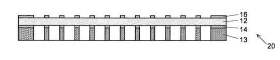
- FIG. 3 is a vertical cross-sectional view showing a seal with a filter and packing material, which includes a filter and packing material, and which is attached to the base during manufacturing of the filter plate of the first embodiment.
- FIG. 2 is an exploded perspective view of a seal with a filter and packing material in the first embodiment.
- FIG. 2 is a vertical cross-sectional view showing a state in which the filter plate of the first embodiment is attached to a microplate.
- FIG. 2 is a schematic diagram showing a state in which a microplate and a filter plate of the first embodiment are attached to a centrifuge.
- the top view (a), bb longitudinal cross-sectional view (b), and bottom view (c) which show 2nd Embodiment of the filter plate based on this invention.
- FIG. 7(a) is a partially enlarged vertical cross-sectional view of the filter plate of the second embodiment
- FIG. 7(b) is a partially enlarged bottom view.
- FIG. 7 is a partially enlarged vertical cross-sectional view showing a state in which the filter plate of the second embodiment is attached to a microplate.
- FIG. 7 is a partial vertical cross-sectional view showing a filter plate according to a modification of the first embodiment.
- filter plate for microplates
- FIG. 1 shows a filter plate 10 of a first embodiment.
- This filter plate 10 has a base 11, a filter sheet 12, and a packing material 13.
- the base 11 includes a plastic plate member 111 having a rectangular planar shape and a plurality of first through holes 112 provided in the plate member 111 and having a circular planar shape.
- a total of 96 first through holes 112 are provided, 12 of which are arranged parallel to the long sides of the rectangle, and 8 of which are arranged parallel to the short sides of the rectangle.
- the arrangement of the first through holes 112 corresponds to the arrangement of the wells of a 96-well microplate to which the filter plate 10 is mounted.
- numbers 1 to 12 are written on the long side end according to the rows in which the first through holes 112 are arranged, and on the short side end, the first through holes 112 are written.
- Eight alphabets from A to H are written along the row with 112. These numbers and alphabets are symbols for specifying each first through hole 112.
- a rectangular frame-shaped vertical wall 114 made of the same material as the base 11 extends downward from the outer peripheral edge of the lower surface.
- the microplate insertion space 115 is basically a rectangular parallelepiped, but a corner portion 116 made of the same material as the vertical wall 114 (FIG. 1(c) ) is provided. That is, the planar shape of the microplate insertion space 115 and the planar shape of the upper surface of the base 11 are almost the same.
- the filter sheet 12 is made of a filter material made of nylon 66 and has an opening (filtration particle size) of 30 ⁇ m.
- One filter sheet 12 has approximately the same shape as the area surrounded by the vertical wall 114 on the lower surface of the base 11, and is attached to the lower surface of the base 11 so as to cover that area.
- the portion of this single filter sheet 12 facing the first through hole 112 functions as the filter of the present invention.
- the packing material 13 is made of a plate-like member 131 that is thicker than the filter sheet 12 and has a second through hole 132 that corresponds to the first through hole 112 of the base 11 .
- the packing material 13 has substantially the same planar shape as the filter sheet 12, and is provided on the lower surface of the base 11 with the filter sheet 12 sandwiched therebetween.
- the plate member 131 of the packing material 13 is made of silicone rubber and has flexibility.
- the filter sheet 12 and the packing material 13 are bonded to each other by a first double-sided adhesive film 14 that has holes provided in positions corresponding to the second through holes 132 of the packing material 13.
- a first double-sided adhesive film 14 that has holes provided in positions corresponding to the second through holes 132 of the packing material 13.
- FIG. 2 in order to clearly display each component, the scales in the horizontal and vertical directions are different (the components are drawn longer in the vertical direction).
- the filter sheet 12 and the base 11 are connected to a second double-sided adhesive film 16 (the illustration of the second double-sided adhesive film 16 is omitted in FIG. ) are glued together.
- Both the first double-sided adhesive film 14 and the second double-sided adhesive film 16 have the same planar shape as the filter sheet 12 or the packing material 13. Therefore, two notches 123, 133, 143 and 163 are provided (see FIG. 3).
- the packing material 13, the first double-sided adhesive film 14, the filter sheet 12, and the second double-sided adhesive film 16 are placed in the respective notches 133, 143, 123, and 163 in order from the bottom. Align, overlap, and paste to integrate.
- this integrated product (this will be referred to as the "seal 20 with filter/packing material") is surrounded by the vertical wall 114 on the lower surface of the base 11 by aligning the notch with the corner part 116 of the base 11.
- the microplate insertion space 115 is fitted into the microplate insertion space 115 , and the second double-sided adhesive film 16 is attached to the lower surface of the base 11 . Thereby, the filter plate 10 is completed.
- a release paper is attached to one surface of the packing material 13, and the release paper is left attached to the packing material 13 when manufacturing the seal 20 with filter/packing material and when manufacturing the filter plate 10.
- the release paper may be peeled off from the packing material 1 immediately before attaching the filter plate 10 to the microplate.
- a 96-hole microplate 90 is prepared that has a shape that corresponds to the microplate insertion space 115 of the filter plate 10. Then, the C-face of this microplate 90 is aligned with the corner portion 116 of the filter plate 10, and the microplate 90 is inserted from its top side into the microplate insertion space 115 of the filter plate 10 ( Figure 4). Next, the microplate 90 and the filter plate 10 are pressed against each other. At this time, since the packing material 13 located between the microplate 90 and the base 11 is flexible, the microplate 90 and the filter plate 10 are pressed against each other, and thus connected in a liquid-tight state with no gaps.
- a predetermined amount of the sample liquid 80 is dropped into each first through hole 112 of the base 11 using a micropipette (not shown).
- the dropped sample liquid 80 only needs to be placed on the filter, and there is no need to forcefully press the tip of the tip attached to the nozzle of the micropipette against the surface of the filter. Therefore, it is not necessary to deeply penetrate the tip into the first through holes 112.
- the sample liquid 80 can be dropped simultaneously into the plurality of first through holes 112 using a multichannel micropipette having a plurality of nozzles. Work can be done easily.
- the microplate 90 and filter plate 10 are set in the holder 701 of the centrifuge 70 with the microplate 90 and filter plate 10 tilted nearly vertically (FIG. 5). .
- they may be fastened together using a rubber band, a clip, or the like.
- the centrifuge 70 is driven to rotate the holder 701 at high speed around the rotating shaft 71 extending in the vertical direction.
- the sample liquid 80 in the first through hole 112 of the filter plate 10 is drawn into the well 91 of the microplate 90 and is filtered when passing through the filter sheet 12.
- FIGS. 6 and 7 show a filter plate 30 of a second embodiment.
- This filter plate 30 has a base 31, a filter sheet 32, a packing material 33, and a cylinder 37.
- the base 31 is made of a plastic plate-like member having a rectangular planar shape, and has a total of 384 planar shapes arranged in parallel with each other, 24 parallel to the long side and 16 parallel to the short side. has a circular first through hole 312 .
- the arrangement of the first through holes 312 corresponds to the arrangement of the wells of a 384-well microplate to which the filter plate 30 is mounted.
- the base 31 consists of a first base 3111 and a second base 3112 attached to the bottom of the first base 3111.
- a rectangular frame-shaped vertical wall 3114 extends downward from the outer periphery of the underside of the first base 3111, and the filter sheet 32 and second base 3112 are attached in order from the first base 3111 side to the part surrounded by the vertical wall 3114 on the underside of the first base 3111.
- the length of the vertical wall 3114 is greater than the combined thickness of the filter sheet 32 and the second base 3112, and the space below the second base 3112 and surrounded by the vertical wall 3114 becomes the microplate insertion space 315.
- the first base 3111 and the second base 3112 each have 384 through holes 3121, 3122, and the first through hole 312 is made up of the through holes 3121, 3122 that correspond to each other when the first base 3111 and the second base 3112 are stacked vertically.
- the through hole 3121 has a cylindrical shape with a uniform inner diameter in the depth direction (vertical direction in FIG. 7(a)), whereas the through hole 3122 has a tapered shape with an inner diameter smaller at the bottom than at the top.
- a cylindrical body 37 is provided on the lower surface of the second base 3112 so as to extend downward from the periphery of the first through hole 312.
- the cylinder 37 is made of the same plastic as the second base 3112 and is integrally molded with the second base 3112.
- the outer diameter of the cylindrical body 37 is slightly smaller than the inner diameter of the wells of the 384-well microplate, and the inner diameter of the cylindrical body 37 is equal to the inner diameter of the through hole 3122 on the lower surface of the second base 3112.
- the length of the cylinder 37 is shorter than the depth of the wells of the 384-well microplate.
- the filter sheet 32 is interposed between the first base 3111 and the second base 3112.
- the material and opening size of the filter sheet 32 are the same as those of the filter sheet 12 of the first embodiment.
- the filter sheet 32 covers the entire upper surface of the second base 3112, and the portion of the filter sheet 32 located within the first through hole 312 functions as a filter of the present invention.
- the packing material 33 is made of a plate-like member made of silicone rubber, and is attached to the second base 3112 so as to cover the lower surface of the second base 3112 other than the cylinder 37. Therefore, the packing material 33 has a second through hole 332 corresponding to the cylindrical body 37.
- the first base 3111 and the filter 32, the filter 32 and the second base 3112, and the second base 3112 and the packing material 33 are each made of an adhesive or an adhesive coated on both sides. It is attached by a sheet.
- the filter plate 30 is used as follows. First, a microplate 90A having 384 wells 91A (384 wells) is prepared. Then, as shown in FIG. 8, the microplate 90A is inserted into the microplate insertion space 315 of the filter plate 30 from its upper surface. At this time, the cylinder 37 corresponding to the position is inserted into each well 91A of the microplate 90A. Next, the microplate 90A and the filter plate 30 are pressed against each other. By pressing the microplate 90A and the filter plate 30 in this way, the flexible packing material 33 comes into close contact with the top surface of the microplate 90A without any gaps, thereby connecting the filter plate 30 and the microplate 90A in a liquid-tight state. be done. The operations from dropping the sample liquid 80 into the first through hole 312 to supplying the sample liquid 80 to the well 91A by applying centrifugal force are the same as in the first embodiment.
- the filter plate 30 since the filter plate 30 is liquid-tightly connected to the microplate 90A by the flexible packing material 33, the sample liquid 80 dropped into the first through-hole 312 is transferred by centrifugal force. This prevents the sample liquid from leaking out and flowing into other wells 91A when the microplate 90A is drawn in. Further, since the cylinder 37 is provided on the lower surface of the base 31 of the filter plate 30, the liquid sample that has passed through the filter can be guided to the vicinity of the bottom of the well 91A of the microplate 90A.
- the filter sheet 32 is sandwiched and fixed between the first base 3111 and the second base 3112, and the filter is tightly stretched in each of the first through holes 312. Therefore, in addition to filtering sample liquids, it can be used to recover intracellular substances such as intracellular nucleic acids and exosomes contained in blood or cell culture fluid.
- the holder 701 of the centrifuge 70 When recovering intracellular substances from cells contained in a sample liquid, the holder 701 of the centrifuge 70 is rotated at a higher speed than when filtering the sample liquid. This generates a large centrifugal force, and the cells in the sample solution are strongly pressed against the filter. Since the filter plate 30 is in a state in which the filters are strongly stretched in each of the first through-holes 312, a large vertical force acts on the cells that are strongly pressed against the filter, and the centrifugal force and the vertical force cause the cells to be separated. Can destroy cells. Destroyed cells and intracellular substances can be separated by appropriately setting the filter aperture.
- the present invention is not limited to the above embodiments, and various modifications are possible.
- the materials of the bases 11, 31, filter sheets 12, 32, and packing materials 13, 33 shown in the above embodiments are merely examples, and other materials may be used.
- the packing materials 13 and 33 may be made of ethylene propylene rubber (EPM (EPR) or EPDM (EPT)), urethane rubber, or the like instead of silicone rubber.
- EPM ethylene propylene rubber
- EPT EPDM
- urethane rubber or the like instead of silicone rubber.
- nylon 66 a polymer material such as polyester, polyethylene, or polypropylene may be used as the material for the filter sheets 12 and 32, or a material other than the polymer material such as metal may be used.
- the opening of the filter sheets 12 and 32 can be set to an appropriate size depending on the intended use of the filter plate.
- the opening can be 1 ⁇ m, 10 ⁇ m, 40 ⁇ m, 70 ⁇ m, 100 ⁇ m, etc.
- a precision filtration filter membrane filter with an opening of less than 1 ⁇ m (so-called submicron) may be used.
- the opening of the filter sheet is preferably 0.1 ⁇ m to 5 ⁇ m.
- a filter plate having first through holes and second through holes whose number and position correspond to the wells of a 96-well microplate is used, and in the second embodiment, the filter plate has a number and position corresponding to the wells of a 384-well microplate.
- the filter plate of the first embodiment and the filter plate of the second embodiment have first through holes and second through holes respectively
- the filter plates of the first embodiment and the filter plate of the second embodiment have first through holes in numbers and positions corresponding to the wells of the microplate.
- the corner portion 116 was provided in the microplate insertion space 115 of the base 11, but the corner portion 116 may be omitted. By omitting the corner portions 116, the filter plate can be used even in microplates that do not have a C-plane.
- the filter corresponding to all the first through holes was constructed from one filter sheet 12, 32, but as in the filter plate 10A shown in FIG. An individual filter 12A may be provided for each.
- the planar shape of the first through holes 112, 312 is circular, but it may be a quadrilateral such as a square, a hexagon such as a regular hexagon, or other shapes. Further, the shape of the vertical cross section of the first through holes 112, 312 is not limited to the above example.
- a microplate filter plate (filter plate) according to one aspect of the present invention, a) a plate-shaped base provided with a first through hole provided at a position corresponding to each of the plurality of wells of the microplate; b) a filter provided in the first through hole; c) a flexible plate-shaped packing material provided on one surface of the base and having a second through hole at a position corresponding to the first through hole.
- the portion of the filter sheet that corresponds to the first through hole serves as a filter.
- the filter plate according to Item 3 further extends from around the first through hole of the base toward the packing material side and passes through the second through hole. It is characterized by having a cylindrical body.
- the filter plate according to Section 4 is the filter plate according to Section 3, which includes:
- the base is a combination of a first plate-shaped base and a second base having the cylinder on one side of the plate-shaped member,
- the filter is characterized in that the filter is provided between the first base and the second base.
- the filter plate according to Item 5 is the filter plate according to any one of Items 1 to 4, characterized in that the material of the packing material is silicone rubber.
Landscapes
- Chemical & Material Sciences (AREA)
- Chemical Kinetics & Catalysis (AREA)
- Health & Medical Sciences (AREA)
- Analytical Chemistry (AREA)
- General Health & Medical Sciences (AREA)
- Hematology (AREA)
- Clinical Laboratory Science (AREA)
- Life Sciences & Earth Sciences (AREA)
- Hydrology & Water Resources (AREA)
- Physics & Mathematics (AREA)
- Biochemistry (AREA)
- General Physics & Mathematics (AREA)
- Immunology (AREA)
- Pathology (AREA)
- Sampling And Sample Adjustment (AREA)
- Automatic Analysis And Handling Materials Therefor (AREA)
Priority Applications (2)
| Application Number | Priority Date | Filing Date | Title |
|---|---|---|---|
| US18/855,820 US20250249459A1 (en) | 2022-09-12 | 2023-07-18 | Microplate filter plate |
| JP2024501977A JP7461097B1 (ja) | 2022-09-12 | 2023-07-18 | マイクロプレート用フィルタプレート |
Applications Claiming Priority (2)
| Application Number | Priority Date | Filing Date | Title |
|---|---|---|---|
| JP2022144791 | 2022-09-12 | ||
| JP2022-144791 | 2022-09-12 |
Publications (1)
| Publication Number | Publication Date |
|---|---|
| WO2024057703A1 true WO2024057703A1 (ja) | 2024-03-21 |
Family
ID=90274616
Family Applications (1)
| Application Number | Title | Priority Date | Filing Date |
|---|---|---|---|
| PCT/JP2023/026264 Ceased WO2024057703A1 (ja) | 2022-09-12 | 2023-07-18 | マイクロプレート用フィルタプレート |
Country Status (3)
| Country | Link |
|---|---|
| US (1) | US20250249459A1 (https=) |
| JP (1) | JP7461097B1 (https=) |
| WO (1) | WO2024057703A1 (https=) |
Cited By (1)
| Publication number | Priority date | Publication date | Assignee | Title |
|---|---|---|---|---|
| JP7595392B1 (ja) * | 2024-03-08 | 2024-12-06 | シーエステック株式会社 | フィルタプレート |
Citations (2)
| Publication number | Priority date | Publication date | Assignee | Title |
|---|---|---|---|---|
| JPH04227032A (ja) * | 1990-07-18 | 1992-08-17 | Bio Rad Lab Inc | マルチサンプル濾過プレート集成装置 |
| WO2007123100A1 (ja) * | 2006-04-20 | 2007-11-01 | Dai Nippon Printing Co., Ltd. | フィルター付きマイクロプレート |
Family Cites Families (14)
| Publication number | Priority date | Publication date | Assignee | Title |
|---|---|---|---|---|
| US4493815A (en) * | 1983-07-28 | 1985-01-15 | Bio-Rad Laboratories, Inc. | Supporting and filtering biochemical test plate assembly |
| JPS60124619U (ja) * | 1984-01-30 | 1985-08-22 | 東洋濾紙株式会社 | マルチフイルター用微多孔性フイルム積層体 |
| US5047215A (en) * | 1985-06-18 | 1991-09-10 | Polyfiltronics, Inc. | Multiwell test plate |
| JP2892813B2 (ja) * | 1990-10-19 | 1999-05-17 | 株式会社丸菱バイオエンジ | 菌体等培養装置に於ける蓋状除菌フイルター並びに該フイルターを用いた菌体等培養装置 |
| US5961926A (en) * | 1993-09-27 | 1999-10-05 | Packard Instrument Co., Inc. | Microplate assembly and method of preparing samples for analysis in a microplate assembly |
| AU744879B2 (en) * | 1997-09-19 | 2002-03-07 | Aclara Biosciences, Inc. | Apparatus and method for transferring liquids |
| US6436351B1 (en) * | 1998-07-15 | 2002-08-20 | Deltagen Research Laboratories, L.L.C. | Microtitre chemical reaction system |
| US6439036B1 (en) * | 2000-06-13 | 2002-08-27 | Symyx Technologics, Inc. | Method for evaluating a test fluid |
| DE10142960C2 (de) * | 2001-09-01 | 2003-12-04 | Eppendorf Ag | Verwendung einer Platte aus elastisch verformbaren Kunststoff oder Gummi zur Abdeckung einer zum Teil befüllten Mikrofiltrationsplatte während der Filtration |
| WO2004043599A1 (en) * | 2002-11-12 | 2004-05-27 | Millipore Corporation | Evaporation control device for multiwell plates |
| US8753588B2 (en) * | 2003-10-15 | 2014-06-17 | Emd Millipore Corporation | Support and stand-off ribs for underdrain for multi-well device |
| JP2007292629A (ja) * | 2006-04-26 | 2007-11-08 | Matsushita Electric Ind Co Ltd | 液体分注装置 |
| DE102010011485A1 (de) * | 2010-03-16 | 2011-09-22 | Sartorius Stedim Biotech Gmbh | Mehrfachlochplatte mit Filtermedium und ihre Verwendung |
| CN216712120U (zh) * | 2022-01-06 | 2022-06-10 | 中山康天晟合生物技术有限公司 | 一种可抑制试剂挥发的培养孔板 |
-
2023
- 2023-07-18 JP JP2024501977A patent/JP7461097B1/ja active Active
- 2023-07-18 WO PCT/JP2023/026264 patent/WO2024057703A1/ja not_active Ceased
- 2023-07-18 US US18/855,820 patent/US20250249459A1/en active Pending
Patent Citations (2)
| Publication number | Priority date | Publication date | Assignee | Title |
|---|---|---|---|---|
| JPH04227032A (ja) * | 1990-07-18 | 1992-08-17 | Bio Rad Lab Inc | マルチサンプル濾過プレート集成装置 |
| WO2007123100A1 (ja) * | 2006-04-20 | 2007-11-01 | Dai Nippon Printing Co., Ltd. | フィルター付きマイクロプレート |
Cited By (1)
| Publication number | Priority date | Publication date | Assignee | Title |
|---|---|---|---|---|
| JP7595392B1 (ja) * | 2024-03-08 | 2024-12-06 | シーエステック株式会社 | フィルタプレート |
Also Published As
| Publication number | Publication date |
|---|---|
| JPWO2024057703A1 (https=) | 2024-03-21 |
| US20250249459A1 (en) | 2025-08-07 |
| JP7461097B1 (ja) | 2024-04-03 |
Similar Documents
| Publication | Publication Date | Title |
|---|---|---|
| US6716350B2 (en) | Microplate protective tray undercover | |
| US5326533A (en) | Multiwell test apparatus | |
| US4948564A (en) | Multi-well filter strip and composite assemblies | |
| US4895706A (en) | Multi-well filter strip and composite assemblies | |
| CN111151175B (zh) | 多孔分离设备和试剂递送装置 | |
| JP7461097B1 (ja) | マイクロプレート用フィルタプレート | |
| US7658886B2 (en) | Universal filtration plate | |
| KR20090007692A (ko) | 필터 부착 마이크로 플레이트 | |
| US6719896B1 (en) | Fluid-filtration receptacle with user-variable semi-permeable drain assembly | |
| DE602004011647T2 (de) | Schicht und Abstehrippen für die Abflussmatte einer Mehrlochtestplatte | |
| CN114728282B (zh) | 材料转移装置及其使用方法 | |
| JP7595392B1 (ja) | フィルタプレート | |
| US20040182770A1 (en) | Combination laboratory device with multifunctionality | |
| WO2003103812A1 (en) | Modular system for separating components of a liquid sample | |
| DE102008017083A1 (de) | Vorrichtung zur Gleichgewichtsdialyse von Flüssigkeiten | |
| EP1560651A1 (en) | Evaporation control device for multiwell plates | |
| EP3621716B1 (en) | Multiwell plate with variable compression seal | |
| EP4498092A1 (en) | Liquid container | |
| KR20260043563A (ko) | 샘플 용기 홀딩용 장치 및 상기 장치를 포함하는 키트 | |
| CN117813514A (zh) | 试验装置 | |
| HK1130896A (en) | Filter-carrying micro plate | |
| HK1237709A1 (en) | Multi-well separation apparatus and reagent delivery device |
Legal Events
| Date | Code | Title | Description |
|---|---|---|---|
| ENP | Entry into the national phase |
Ref document number: 2024501977 Country of ref document: JP Kind code of ref document: A |
|
| 121 | Ep: the epo has been informed by wipo that ep was designated in this application |
Ref document number: 23865065 Country of ref document: EP Kind code of ref document: A1 |
|
| WWE | Wipo information: entry into national phase |
Ref document number: 18855820 Country of ref document: US |
|
| NENP | Non-entry into the national phase |
Ref country code: DE |
|
| WWP | Wipo information: published in national office |
Ref document number: 18855820 Country of ref document: US |
|
| 122 | Ep: pct application non-entry in european phase |
Ref document number: 23865065 Country of ref document: EP Kind code of ref document: A1 |