WO2024057703A1 - マイクロプレート用フィルタプレート - Google Patents
マイクロプレート用フィルタプレート Download PDFInfo
- Publication number
- WO2024057703A1 WO2024057703A1 PCT/JP2023/026264 JP2023026264W WO2024057703A1 WO 2024057703 A1 WO2024057703 A1 WO 2024057703A1 JP 2023026264 W JP2023026264 W JP 2023026264W WO 2024057703 A1 WO2024057703 A1 WO 2024057703A1
- Authority
- WO
- WIPO (PCT)
- Prior art keywords
- filter
- base
- microplate
- filter plate
- plate
- Prior art date
Links
- 238000012856 packing Methods 0.000 claims abstract description 51
- 239000000463 material Substances 0.000 claims description 60
- 229920002379 silicone rubber Polymers 0.000 claims description 6
- 239000004945 silicone rubber Substances 0.000 claims description 6
- 239000007788 liquid Substances 0.000 description 41
- 239000000523 sample Substances 0.000 description 41
- 239000002313 adhesive film Substances 0.000 description 11
- 238000003780 insertion Methods 0.000 description 11
- 230000037431 insertion Effects 0.000 description 11
- 238000001914 filtration Methods 0.000 description 7
- 229920000181 Ethylene propylene rubber Polymers 0.000 description 6
- 210000004027 cell Anatomy 0.000 description 6
- 238000004519 manufacturing process Methods 0.000 description 6
- 230000003834 intracellular effect Effects 0.000 description 5
- 239000000126 substance Substances 0.000 description 4
- 238000012986 modification Methods 0.000 description 3
- 230000004048 modification Effects 0.000 description 3
- 239000004033 plastic Substances 0.000 description 3
- 229920003023 plastic Polymers 0.000 description 3
- 239000012488 sample solution Substances 0.000 description 3
- 229920002943 EPDM rubber Polymers 0.000 description 2
- VGGSQFUCUMXWEO-UHFFFAOYSA-N Ethene Chemical compound C=C VGGSQFUCUMXWEO-UHFFFAOYSA-N 0.000 description 2
- 239000005977 Ethylene Substances 0.000 description 2
- 229920002302 Nylon 6,6 Polymers 0.000 description 2
- 229920006311 Urethane elastomer Polymers 0.000 description 2
- 239000000853 adhesive Substances 0.000 description 2
- 230000001070 adhesive effect Effects 0.000 description 2
- 239000000428 dust Substances 0.000 description 2
- 229920001971 elastomer Polymers 0.000 description 2
- 210000001808 exosome Anatomy 0.000 description 2
- -1 polyethylene Polymers 0.000 description 2
- 239000002861 polymer material Substances 0.000 description 2
- QQONPFPTGQHPMA-UHFFFAOYSA-N propylene Natural products CC=C QQONPFPTGQHPMA-UHFFFAOYSA-N 0.000 description 2
- 125000004805 propylene group Chemical group [H]C([H])([H])C([H])([*:1])C([H])([H])[*:2] 0.000 description 2
- 239000004698 Polyethylene Substances 0.000 description 1
- 239000004743 Polypropylene Substances 0.000 description 1
- 238000004458 analytical method Methods 0.000 description 1
- 210000004369 blood Anatomy 0.000 description 1
- 239000008280 blood Substances 0.000 description 1
- 238000009640 blood culture Methods 0.000 description 1
- 239000012930 cell culture fluid Substances 0.000 description 1
- 229920001577 copolymer Polymers 0.000 description 1
- 238000010586 diagram Methods 0.000 description 1
- 239000000806 elastomer Substances 0.000 description 1
- 239000012535 impurity Substances 0.000 description 1
- 238000009434 installation Methods 0.000 description 1
- 239000012528 membrane Substances 0.000 description 1
- 239000002184 metal Substances 0.000 description 1
- 238000000034 method Methods 0.000 description 1
- 239000000203 mixture Substances 0.000 description 1
- 238000000465 moulding Methods 0.000 description 1
- 150000007523 nucleic acids Chemical class 0.000 description 1
- 102000039446 nucleic acids Human genes 0.000 description 1
- 108020004707 nucleic acids Proteins 0.000 description 1
- 239000002245 particle Substances 0.000 description 1
- 230000002093 peripheral effect Effects 0.000 description 1
- 229920000728 polyester Polymers 0.000 description 1
- 229920000573 polyethylene Polymers 0.000 description 1
- 229920001155 polypropylene Polymers 0.000 description 1
- 238000003825 pressing Methods 0.000 description 1
- 229920001897 terpolymer Polymers 0.000 description 1
Images


Classifications
-
- G—PHYSICS
- G01—MEASURING; TESTING
- G01N—INVESTIGATING OR ANALYSING MATERIALS BY DETERMINING THEIR CHEMICAL OR PHYSICAL PROPERTIES
- G01N1/00—Sampling; Preparing specimens for investigation
- G01N1/02—Devices for withdrawing samples
- G01N1/10—Devices for withdrawing samples in the liquid or fluent state
Definitions
- the present invention relates to a filter plate used for filtering a sample liquid when injecting the sample liquid into the wells of a microplate.
- Patent Document 1 discloses a filter plate for microplates in which a plate member is provided with through holes corresponding to the positions of each well of a microplate, and one filter is provided at the bottom of each through hole. Are listed. A guide wall extending downward from the periphery of the through hole is provided on the lower surface of the plate member. This filter plate is used in a state where it is stacked on top of a microplate and each guide wall is inserted into a well at a corresponding position, and in this state, a sample liquid is dropped onto the filter in each through hole.
- the microplate is set in the holder of a centrifuge with the microplate tilted nearly vertically (in other words, the through-holes are tilted nearly horizontally) to the extent that the sample liquid dropped onto the filter does not fall out of the through-holes. be done.
- the centrifuge is driven in this state, the holder rotates at high speed around the vertical axis, and the sample liquid on the filter is drawn into the well by centrifugal force.
- there is a gap between the outer surface of the guide wall and the edge of the well there is a risk that the sample liquid will leak from there and flow into other wells. In this case, different sample liquids will mix with each other, making it impossible to perform accurate analysis.
- the problem to be solved by the present invention is to provide a filter plate for a microplate that can prevent mixing of sample liquids when filtering the sample liquids with a filter.
- the filter plate for microplates has been made to solve the above problems, a) a plate-shaped base provided with a first through hole provided at a position corresponding to each of the plurality of wells of the microplate; b) a filter provided in the first through hole; c) a flexible plate-shaped packing material provided on one surface of the base and having a second through hole at a position corresponding to the first through hole.
- the filter plate for microplates (hereinafter referred to as "filter plate”) according to the present invention is used by stacking it on a microplate. Specifically, the base is placed on the microplate with the side provided with the packing material facing the top surface of the microplate and the second through holes aligned with each of the plurality of wells of the microplate. Overlap. In this state, the sample liquid is dripped onto the filter from the first through-hole, and then the filter plate is strongly pressed against the microplate side, and the filter plate is set in a centrifuge with the packing material in contact with the top surface of the microplate. When the centrifuge is driven, the sample solution dropped onto the filter passes through the filter due to centrifugal force and is drawn into the well.
- the flexible packing material is interposed between the filter plate and the microplate, the space between them becomes liquid-tight. This prevents the sample liquid from leaking out between the filter plate and the microplate and flowing into other wells when the sample liquid that has passed through the filter is drawn into each well, allowing different sample liquids to mix with each other. You can prevent it from happening.
- one (integral) filter that covers all of the plurality of first through holes of the base may be provided in the first through hole. It is preferable that it is provided between one surface of the base and the packing material.
- the filter plate according to the present invention may further include a cylindrical body extending from around the first through hole of the base toward the packing material side and passing through the second through hole.
- the cylinder When using a filter plate equipped with such a cylinder, the cylinder is inserted into each of the multiple wells of the microplate, and the packing material is then placed in contact with the top surface of the microplate. When setting it in the centrifuge, the packing material is pressed against the top surface of the microplate. This allows the sample liquid to pass through the filter by centrifugal force, then pass through the cylinder and be introduced into the wells. Even when equipped with such a cylinder, the provision of packing material can prevent the sample liquid from flowing into other wells, and prevents different sample liquids from mixing together.
- the base is a combination of a first plate-shaped base and a second base having the cylinder on one side of the plate-shaped member, A configuration may be adopted in which the filter is provided between the first base and the second base.
- the filter between the first base and the second base in this way, it is possible to reduce the effort required to attach the filter.
- separate filters may be provided in each of the first through holes, but it is better to use one filter that spans a plurality of first through holes to further reduce the installation effort.
- the second base may be formed by assembling a plate-like member and a cylinder that are separate from each other, but it is easier to assemble the plate-like member and the cylinder by integrally molding the plate-like member and the cylinder. This is preferable because it allows for
- Packing materials include, for example, silicone rubber, ethylene propylene rubber (EPM (also referred to as EPR), which is a copolymer of ethylene and propylene, or a terpolymer of ethylene and propylene with a small amount of a third component added).
- Elastomers such as certain EPDM (also referred to as EPT) and urethane rubber can be suitably used.
- the filter plate for microplates according to the present invention can prevent mixing of sample liquids when filtering the sample liquid with a filter.
- FIG. 1 is a top view (a), an a-a vertical sectional view (b), and a bottom view (c) showing a first embodiment of a filter plate for a microplate according to the present invention.
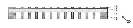
- FIG. 3 is a vertical cross-sectional view showing a seal with a filter and packing material, which includes a filter and packing material, and which is attached to the base during manufacturing of the filter plate of the first embodiment.
- FIG. 2 is an exploded perspective view of a seal with a filter and packing material in the first embodiment.
- FIG. 2 is a vertical cross-sectional view showing a state in which the filter plate of the first embodiment is attached to a microplate.
- FIG. 2 is a schematic diagram showing a state in which a microplate and a filter plate of the first embodiment are attached to a centrifuge.
- the top view (a), bb longitudinal cross-sectional view (b), and bottom view (c) which show 2nd Embodiment of the filter plate based on this invention.
- FIG. 7(a) is a partially enlarged vertical cross-sectional view of the filter plate of the second embodiment
- FIG. 7(b) is a partially enlarged bottom view.
- FIG. 7 is a partially enlarged vertical cross-sectional view showing a state in which the filter plate of the second embodiment is attached to a microplate.
- FIG. 7 is a partial vertical cross-sectional view showing a filter plate according to a modification of the first embodiment.
- filter plate for microplates
- FIG. 1 shows a filter plate 10 of a first embodiment.
- This filter plate 10 has a base 11, a filter sheet 12, and a packing material 13.
- the base 11 includes a plastic plate member 111 having a rectangular planar shape and a plurality of first through holes 112 provided in the plate member 111 and having a circular planar shape.
- a total of 96 first through holes 112 are provided, 12 of which are arranged parallel to the long sides of the rectangle, and 8 of which are arranged parallel to the short sides of the rectangle.
- the arrangement of the first through holes 112 corresponds to the arrangement of the wells of a 96-well microplate to which the filter plate 10 is mounted.
- numbers 1 to 12 are written on the long side end according to the rows in which the first through holes 112 are arranged, and on the short side end, the first through holes 112 are written.
- Eight alphabets from A to H are written along the row with 112. These numbers and alphabets are symbols for specifying each first through hole 112.
- a rectangular frame-shaped vertical wall 114 made of the same material as the base 11 extends downward from the outer peripheral edge of the lower surface.
- the microplate insertion space 115 is basically a rectangular parallelepiped, but a corner portion 116 made of the same material as the vertical wall 114 (FIG. 1(c) ) is provided. That is, the planar shape of the microplate insertion space 115 and the planar shape of the upper surface of the base 11 are almost the same.
- the filter sheet 12 is made of a filter material made of nylon 66 and has an opening (filtration particle size) of 30 ⁇ m.
- One filter sheet 12 has approximately the same shape as the area surrounded by the vertical wall 114 on the lower surface of the base 11, and is attached to the lower surface of the base 11 so as to cover that area.
- the portion of this single filter sheet 12 facing the first through hole 112 functions as the filter of the present invention.
- the packing material 13 is made of a plate-like member 131 that is thicker than the filter sheet 12 and has a second through hole 132 that corresponds to the first through hole 112 of the base 11 .
- the packing material 13 has substantially the same planar shape as the filter sheet 12, and is provided on the lower surface of the base 11 with the filter sheet 12 sandwiched therebetween.
- the plate member 131 of the packing material 13 is made of silicone rubber and has flexibility.
- the filter sheet 12 and the packing material 13 are bonded to each other by a first double-sided adhesive film 14 that has holes provided in positions corresponding to the second through holes 132 of the packing material 13.
- a first double-sided adhesive film 14 that has holes provided in positions corresponding to the second through holes 132 of the packing material 13.
- FIG. 2 in order to clearly display each component, the scales in the horizontal and vertical directions are different (the components are drawn longer in the vertical direction).
- the filter sheet 12 and the base 11 are connected to a second double-sided adhesive film 16 (the illustration of the second double-sided adhesive film 16 is omitted in FIG. ) are glued together.
- Both the first double-sided adhesive film 14 and the second double-sided adhesive film 16 have the same planar shape as the filter sheet 12 or the packing material 13. Therefore, two notches 123, 133, 143 and 163 are provided (see FIG. 3).
- the packing material 13, the first double-sided adhesive film 14, the filter sheet 12, and the second double-sided adhesive film 16 are placed in the respective notches 133, 143, 123, and 163 in order from the bottom. Align, overlap, and paste to integrate.
- this integrated product (this will be referred to as the "seal 20 with filter/packing material") is surrounded by the vertical wall 114 on the lower surface of the base 11 by aligning the notch with the corner part 116 of the base 11.
- the microplate insertion space 115 is fitted into the microplate insertion space 115 , and the second double-sided adhesive film 16 is attached to the lower surface of the base 11 . Thereby, the filter plate 10 is completed.
- a release paper is attached to one surface of the packing material 13, and the release paper is left attached to the packing material 13 when manufacturing the seal 20 with filter/packing material and when manufacturing the filter plate 10.
- the release paper may be peeled off from the packing material 1 immediately before attaching the filter plate 10 to the microplate.
- a 96-hole microplate 90 is prepared that has a shape that corresponds to the microplate insertion space 115 of the filter plate 10. Then, the C-face of this microplate 90 is aligned with the corner portion 116 of the filter plate 10, and the microplate 90 is inserted from its top side into the microplate insertion space 115 of the filter plate 10 ( Figure 4). Next, the microplate 90 and the filter plate 10 are pressed against each other. At this time, since the packing material 13 located between the microplate 90 and the base 11 is flexible, the microplate 90 and the filter plate 10 are pressed against each other, and thus connected in a liquid-tight state with no gaps.
- a predetermined amount of the sample liquid 80 is dropped into each first through hole 112 of the base 11 using a micropipette (not shown).
- the dropped sample liquid 80 only needs to be placed on the filter, and there is no need to forcefully press the tip of the tip attached to the nozzle of the micropipette against the surface of the filter. Therefore, it is not necessary to deeply penetrate the tip into the first through holes 112.
- the sample liquid 80 can be dropped simultaneously into the plurality of first through holes 112 using a multichannel micropipette having a plurality of nozzles. Work can be done easily.
- the microplate 90 and filter plate 10 are set in the holder 701 of the centrifuge 70 with the microplate 90 and filter plate 10 tilted nearly vertically (FIG. 5). .
- they may be fastened together using a rubber band, a clip, or the like.
- the centrifuge 70 is driven to rotate the holder 701 at high speed around the rotating shaft 71 extending in the vertical direction.
- the sample liquid 80 in the first through hole 112 of the filter plate 10 is drawn into the well 91 of the microplate 90 and is filtered when passing through the filter sheet 12.
- FIGS. 6 and 7 show a filter plate 30 of a second embodiment.
- This filter plate 30 has a base 31, a filter sheet 32, a packing material 33, and a cylinder 37.
- the base 31 is made of a plastic plate-like member having a rectangular planar shape, and has a total of 384 planar shapes arranged in parallel with each other, 24 parallel to the long side and 16 parallel to the short side. has a circular first through hole 312 .
- the arrangement of the first through holes 312 corresponds to the arrangement of the wells of a 384-well microplate to which the filter plate 30 is mounted.
- the base 31 consists of a first base 3111 and a second base 3112 attached to the bottom of the first base 3111.
- a rectangular frame-shaped vertical wall 3114 extends downward from the outer periphery of the underside of the first base 3111, and the filter sheet 32 and second base 3112 are attached in order from the first base 3111 side to the part surrounded by the vertical wall 3114 on the underside of the first base 3111.
- the length of the vertical wall 3114 is greater than the combined thickness of the filter sheet 32 and the second base 3112, and the space below the second base 3112 and surrounded by the vertical wall 3114 becomes the microplate insertion space 315.
- the first base 3111 and the second base 3112 each have 384 through holes 3121, 3122, and the first through hole 312 is made up of the through holes 3121, 3122 that correspond to each other when the first base 3111 and the second base 3112 are stacked vertically.
- the through hole 3121 has a cylindrical shape with a uniform inner diameter in the depth direction (vertical direction in FIG. 7(a)), whereas the through hole 3122 has a tapered shape with an inner diameter smaller at the bottom than at the top.
- a cylindrical body 37 is provided on the lower surface of the second base 3112 so as to extend downward from the periphery of the first through hole 312.
- the cylinder 37 is made of the same plastic as the second base 3112 and is integrally molded with the second base 3112.
- the outer diameter of the cylindrical body 37 is slightly smaller than the inner diameter of the wells of the 384-well microplate, and the inner diameter of the cylindrical body 37 is equal to the inner diameter of the through hole 3122 on the lower surface of the second base 3112.
- the length of the cylinder 37 is shorter than the depth of the wells of the 384-well microplate.
- the filter sheet 32 is interposed between the first base 3111 and the second base 3112.
- the material and opening size of the filter sheet 32 are the same as those of the filter sheet 12 of the first embodiment.
- the filter sheet 32 covers the entire upper surface of the second base 3112, and the portion of the filter sheet 32 located within the first through hole 312 functions as a filter of the present invention.
- the packing material 33 is made of a plate-like member made of silicone rubber, and is attached to the second base 3112 so as to cover the lower surface of the second base 3112 other than the cylinder 37. Therefore, the packing material 33 has a second through hole 332 corresponding to the cylindrical body 37.
- the first base 3111 and the filter 32, the filter 32 and the second base 3112, and the second base 3112 and the packing material 33 are each made of an adhesive or an adhesive coated on both sides. It is attached by a sheet.
- the filter plate 30 is used as follows. First, a microplate 90A having 384 wells 91A (384 wells) is prepared. Then, as shown in FIG. 8, the microplate 90A is inserted into the microplate insertion space 315 of the filter plate 30 from its upper surface. At this time, the cylinder 37 corresponding to the position is inserted into each well 91A of the microplate 90A. Next, the microplate 90A and the filter plate 30 are pressed against each other. By pressing the microplate 90A and the filter plate 30 in this way, the flexible packing material 33 comes into close contact with the top surface of the microplate 90A without any gaps, thereby connecting the filter plate 30 and the microplate 90A in a liquid-tight state. be done. The operations from dropping the sample liquid 80 into the first through hole 312 to supplying the sample liquid 80 to the well 91A by applying centrifugal force are the same as in the first embodiment.
- the filter plate 30 since the filter plate 30 is liquid-tightly connected to the microplate 90A by the flexible packing material 33, the sample liquid 80 dropped into the first through-hole 312 is transferred by centrifugal force. This prevents the sample liquid from leaking out and flowing into other wells 91A when the microplate 90A is drawn in. Further, since the cylinder 37 is provided on the lower surface of the base 31 of the filter plate 30, the liquid sample that has passed through the filter can be guided to the vicinity of the bottom of the well 91A of the microplate 90A.
- the filter sheet 32 is sandwiched and fixed between the first base 3111 and the second base 3112, and the filter is tightly stretched in each of the first through holes 312. Therefore, in addition to filtering sample liquids, it can be used to recover intracellular substances such as intracellular nucleic acids and exosomes contained in blood or cell culture fluid.
- the holder 701 of the centrifuge 70 When recovering intracellular substances from cells contained in a sample liquid, the holder 701 of the centrifuge 70 is rotated at a higher speed than when filtering the sample liquid. This generates a large centrifugal force, and the cells in the sample solution are strongly pressed against the filter. Since the filter plate 30 is in a state in which the filters are strongly stretched in each of the first through-holes 312, a large vertical force acts on the cells that are strongly pressed against the filter, and the centrifugal force and the vertical force cause the cells to be separated. Can destroy cells. Destroyed cells and intracellular substances can be separated by appropriately setting the filter aperture.
- the present invention is not limited to the above embodiments, and various modifications are possible.
- the materials of the bases 11, 31, filter sheets 12, 32, and packing materials 13, 33 shown in the above embodiments are merely examples, and other materials may be used.
- the packing materials 13 and 33 may be made of ethylene propylene rubber (EPM (EPR) or EPDM (EPT)), urethane rubber, or the like instead of silicone rubber.
- EPM ethylene propylene rubber
- EPT EPDM
- urethane rubber or the like instead of silicone rubber.
- nylon 66 a polymer material such as polyester, polyethylene, or polypropylene may be used as the material for the filter sheets 12 and 32, or a material other than the polymer material such as metal may be used.
- the opening of the filter sheets 12 and 32 can be set to an appropriate size depending on the intended use of the filter plate.
- the opening can be 1 ⁇ m, 10 ⁇ m, 40 ⁇ m, 70 ⁇ m, 100 ⁇ m, etc.
- a precision filtration filter membrane filter with an opening of less than 1 ⁇ m (so-called submicron) may be used.
- the opening of the filter sheet is preferably 0.1 ⁇ m to 5 ⁇ m.
- a filter plate having first through holes and second through holes whose number and position correspond to the wells of a 96-well microplate is used, and in the second embodiment, the filter plate has a number and position corresponding to the wells of a 384-well microplate.
- the filter plate of the first embodiment and the filter plate of the second embodiment have first through holes and second through holes respectively
- the filter plates of the first embodiment and the filter plate of the second embodiment have first through holes in numbers and positions corresponding to the wells of the microplate.
- the corner portion 116 was provided in the microplate insertion space 115 of the base 11, but the corner portion 116 may be omitted. By omitting the corner portions 116, the filter plate can be used even in microplates that do not have a C-plane.
- the filter corresponding to all the first through holes was constructed from one filter sheet 12, 32, but as in the filter plate 10A shown in FIG. An individual filter 12A may be provided for each.
- the planar shape of the first through holes 112, 312 is circular, but it may be a quadrilateral such as a square, a hexagon such as a regular hexagon, or other shapes. Further, the shape of the vertical cross section of the first through holes 112, 312 is not limited to the above example.
- a microplate filter plate (filter plate) according to one aspect of the present invention, a) a plate-shaped base provided with a first through hole provided at a position corresponding to each of the plurality of wells of the microplate; b) a filter provided in the first through hole; c) a flexible plate-shaped packing material provided on one surface of the base and having a second through hole at a position corresponding to the first through hole.
- the portion of the filter sheet that corresponds to the first through hole serves as a filter.
- the filter plate according to Item 3 further extends from around the first through hole of the base toward the packing material side and passes through the second through hole. It is characterized by having a cylindrical body.
- the filter plate according to Section 4 is the filter plate according to Section 3, which includes:
- the base is a combination of a first plate-shaped base and a second base having the cylinder on one side of the plate-shaped member,
- the filter is characterized in that the filter is provided between the first base and the second base.
- the filter plate according to Item 5 is the filter plate according to any one of Items 1 to 4, characterized in that the material of the packing material is silicone rubber.
Landscapes
- Life Sciences & Earth Sciences (AREA)
- Hydrology & Water Resources (AREA)
- Physics & Mathematics (AREA)
- Health & Medical Sciences (AREA)
- Chemical & Material Sciences (AREA)
- Analytical Chemistry (AREA)
- Biochemistry (AREA)
- General Health & Medical Sciences (AREA)
- General Physics & Mathematics (AREA)
- Immunology (AREA)
- Pathology (AREA)
- Sampling And Sample Adjustment (AREA)
Abstract
マイクロプレート用フィルタプレート10は、マイクロプレート90の複数のウェル91のそれぞれに対応する位置に設けられた第1貫通孔112を備える板状の基部11と、第1貫通孔112に設けられたフィルタ12と、基部11の一方の面に設けられた、第1貫通孔112に対応する位置に第2貫通孔132を有する、柔軟性を有する板状のパッキン材13とを備える。
Description
本発明は、マイクロプレートのウェルに試料液を注入する際に該試料液を濾過するために用いられるフィルタプレートに関する。
従来より、マイクロプレートのウェルに生体由来等の試料液を注入する際に、試料液に含まれる不純物を除去するためのフィルタが用いられている。通常はフィルタの目が小さいため、単に試料液をフィルタ上に滴下しただけでは、表面張力により試料液がフィルタを通過しない。そのため、従来はピペットをフィルタの表面に押しつけたうえで試料液をピペットから押し出すという操作が行われていた。最近ではその代わりに、各ウェルに対応して設けられたフィルタに試料液を滴下した後に、遠心機を用いて遠心力を付与することにより試料液をウェル内に引き込むという操作も行われている。
例えば特許文献1には、板状部材にマイクロプレートの各ウェルの位置に対応してそれぞれ貫通孔が設けられると共に、各貫通孔の下部に1つずつフィルタが設けられたマイクロプレート用フィルタプレートが記載されている。板状部材の下面には、貫通孔の周囲から下方に延びる案内壁が設けられている。このフィルタプレートは、マイクロプレートの上に重ねて各案内壁をそれに対応する位置のウェル内に挿入した状態で用いられ、この状態で各貫通孔のフィルタ上に試料液を滴下する。
通常、マイクロプレートは、そのフィルタに滴下された試料液が貫通孔からこぼれ落ちない程度に鉛直方向近くまで傾けた状態(つまり貫通孔が水平方向近くまで傾いた状態)で遠心機の保持具にセットされる。この状態で遠心機を駆動すると、前記保持具が鉛直方向の軸を中心に高速で回転し、遠心力によってフィルタ上の試料液がウェルにひき込まれる。このとき、案内壁の外面とウェルの縁との間に隙間があると、そこから試料液が漏れ出し、他のウェルに流入してしまうおそれがある。そうすると、異なる試料液同士が混合してしまい、正確な分析を行うことができない。
本発明が解決しようとする課題は、試料液をフィルタで濾過する際に試料液の混合が生じることを防ぐことができるマイクロプレート用フィルタプレートを提供することである。
上記課題を解決するために成された本発明に係るマイクロプレート用フィルタプレートは、
a) マイクロプレートの複数のウェルのそれぞれに対応する位置に設けられた第1貫通孔を備える板状の基部と、
b) 前記第1貫通孔に設けられたフィルタと、
c) 前記基部の一方の面に設けられた、前記第1貫通孔に対応する位置に第2貫通孔を有する、柔軟性を有する板状のパッキン材と
を備えることを特徴とする。
a) マイクロプレートの複数のウェルのそれぞれに対応する位置に設けられた第1貫通孔を備える板状の基部と、
b) 前記第1貫通孔に設けられたフィルタと、
c) 前記基部の一方の面に設けられた、前記第1貫通孔に対応する位置に第2貫通孔を有する、柔軟性を有する板状のパッキン材と
を備えることを特徴とする。
本発明に係るマイクロプレート用フィルタプレート(以下、「フィルタプレート」という。)は、マイクロプレートの上に重ねて使用される。具体的には、基部を、そのパッキン材が設けられた側がマイクロプレートの上面を向けて、該マイクロプレートの複数のウェルのそれぞれと第2貫通孔を一致させた状態で、マイクロプレートの上に重ねる。この状態で、第1貫通孔からフィルタ上に試料液を滴下し、その後、フィルタプレートをマイクロプレート側に強く押しつけてパッキン材をマイクロプレートの上面に当接させた状態で遠心機にセットする。遠心機を駆動すると、フィルタ上に滴下された試料液が遠心力によりフィルタを通過し、ウェルに引き込まれる。フィルタプレートとマイクロプレートの間に柔軟性を有するパッキン材が介在するため、両者の間が液密になる。これにより、フィルタを通過した試料液が各ウェルに引き込まれるときに、該試料液がフィルタプレートとマイクロプレートの間から漏れ出して他のウェルに流入することが阻止され、異なる試料液同士が混合してしまうことを防ぐことができる。
フィルタは互いに分離したものを個々の第1貫通孔に1つずつ設けてもよいが、前記基部が有する複数の前記第1貫通孔の全てを覆うような1枚の(一体の)フィルタが前記基部の一方の面と前記パッキン材との間に設けられていることが好ましい。このような1枚のフィルタを用いることにより、フィルタを取りつける手間を抑えることができる。
本発明に係るフィルタプレートは、さらに、前記基部の第1貫通孔の周囲から前記パッキン材側に延び、前記第2貫通孔を通過する筒体を備えるようにすることができる。
このような筒体を備えるフィルタプレートを使用する際には、マイクロプレートの複数のウェルのそれぞれに筒体を挿入したうえで、パッキン材をマイクロプレートの上面に当接させる。遠心機にセットする際にはパッキン材をマイクロプレートの上面に押しつける。これにより、試料液は遠心力でフィルタを通過した後に筒体内を通過してウェルに導入される。このような筒体を備える場合にも、パッキン材を設けることにより、試料液が他のウェルに流入することを阻止し、異なる試料液同士が混合してしまうことを防ぐことができる。
このような筒体を備えるフィルタプレートにおいて、
前記基部が、板状の第1基部と、板状の部材の一方の面に前記筒体を有する第2基部とを重ねたものであって、
前記フィルタが前記第1基部と前記第2基部との間に設けられている
という構成を取ることができる。
前記基部が、板状の第1基部と、板状の部材の一方の面に前記筒体を有する第2基部とを重ねたものであって、
前記フィルタが前記第1基部と前記第2基部との間に設けられている
という構成を取ることができる。
このように第1基部と第2基部との間にフィルタを設けることにより、フィルタを取りつける手間を抑えることができる。なお、フィルタは互いに分離したものを個々の第1貫通孔に1つずつ設けてもよいが、複数の第1貫通孔に亘る1枚のフィルタを用いる方が、取りつけの手間をより抑えることができる。また、第2基部は互いに別体である板状の部材と筒体を組み立てたものであってもよいが、板状の部材と筒体を一体成形で形成する方が組み立ての手間を省くことができるため好ましい。
パッキン材の材料には、例えばシリコーンゴム、エチレンプロピレンゴム(エチレンとプロピレンの共重合体であるEPM(EPRとも言う)、又は、エチレン及びプロピレンに少量の第三成分を添加した三元重合体であるEPDM(EPTとも言う))、ウレタンゴム等のエラストマーを好適に用いることができる。
本発明に係るマイクロプレート用フィルタプレートにより、試料液をフィルタで濾過する際に試料液の混合が生じることを防ぐことができる。
図1~図9を用いて、本発明に係るマイクロプレート用フィルタプレート(以下、「フィルタプレート」とする)の実施形態を説明する。
(1) 第1実施形態
図1に、第1実施形態のフィルタプレート10を示す。このフィルタプレート10は、基部11と、フィルタシート12と、パッキン材13とを有する。
図1に、第1実施形態のフィルタプレート10を示す。このフィルタプレート10は、基部11と、フィルタシート12と、パッキン材13とを有する。
基部11は、平面形状が長方形であるプラスチック製の板状部材111と、該板状部材111に設けられた複数の平面形状が円形の第1貫通孔112とを有する。第1貫通孔112は、前記長方形の長辺に平行に12個、短辺に平行に8個、それぞれ並ぶように、合計96個設けられている。この第1貫通孔112の配置は、フィルタプレート10が装着される96穴マイクロプレートのウェルの配置に対応している。基部11の上面のうち、長辺側の端部には第1貫通孔112が並ぶ列に合わせて1~12の数字が記載されていると共に、短辺側の端部には第1貫通孔112が並ぶ行に合わせてA~Hの8個のアルファベットが記載されている。これらの数字及びアルファベットは、各第1貫通孔112を特定するための記号である。
基部11(板状部材111)の長方形の4個の角のうち一方の短辺を介して隣り合う2つの角には、該短辺に対して45°の角度で切り落とされたC面113が形成されている。C面113を設けたことにより、フィルタプレート10の向きを容易に認識することができる。
基部11の下面には、該下面の外周縁から下方に向けて、基部11と同じ材料から成る矩形枠状の垂直壁114が延びている。該下面の下方であって垂直壁114で囲まれた部分は、96穴マイクロプレートが挿入されるマイクロプレート挿入空間115となる。マイクロプレート挿入空間115は基本的には直方体であるが、当該直方体のうち基部11がC面113で切り落とされた部分の直下には垂直壁114と同じ材料から成るコーナー部116(図1(c)参照)が設けられている。つまり、マイクロプレート挿入空間115の平面形状と基部11の上面の平面形状は、ほぼ同じである。
フィルタシート12は、ナイロン66製の目開き(ろ過粒度)が30μmのフィルタ材からなる。1枚のフィルタシート12は、基部11の下面のうち垂直壁114で囲まれた領域とほぼ同じ形状であり、その領域を覆うように基部11の下面に取り付けられている。この1枚のフィルタシート12のうち第1貫通孔112に面する部分が、本発明のフィルタとして機能する。
パッキン材13は、基部11の第1貫通孔112に対応する第2貫通孔132が形成された、フィルタシート12よりも厚さの大きい板状部材131からなる。パッキン材13はフィルタシート12とほぼ同じ平面形状を有しており、フィルタシート12を間に挟むようにして基部11の下面に設けられている。パッキン材13の板状部材131はシリコーンゴム製であり、柔軟性を有する。
図2及び図3に示すように、フィルタシート12とパッキン材13は、パッキン材13の第2貫通孔132に対応する位置に孔が設けられた第1両面接着フィルム14により互いに接着されている(図1では第1両面接着フィルム14の図示を省略している)。なお、図2では各構成要素を明瞭に表示するために横方向と縦方向の縮尺を異ならせて(縦方向に長くなるように)描いている。また、フィルタシート12と基部11は、基部11の第1貫通孔112に対応する位置に孔が設けられた第2両面接着フィルム16(図1では第2両面接着フィルム16の図示を省略している。)により互いに接着されている。第1両面接着フィルム14及び第2両面接着フィルム16はいずれもフィルタシート12又はパッキン材13と同じ平面形状である。そのため、フィルタシート12、パッキン材13、第1両面接着フィルム14及び第2両面接着フィルム16の基部11の2個のC面に対応する2箇所には、それぞれ2個の切り欠き123、133、143及び163が設けられている(図3参照)。
フィルタプレート10を製造する際は、まずは、パッキン材13、第1両面接着フィルム14、フィルタシート12及び第2両面接着フィルム16を、下から順に、それぞれの切り欠き133、143、123及び163の位置を合わせて重ね、貼り合わせて一体化する。つぎに、この一体化物(これを「フィルタ・パッキン材付きシール20」と呼ぶ。)を、その切り欠きと基部11のコーナー部116の位置を合わせて、基部11の下面の垂直壁114で囲まれた空間(マイクロプレート挿入空間115)に嵌め込み、第2両面接着フィルム16によって基部11の下面に貼付する。これにより、フィルタプレート10が完成する。
なお、パッキン材13の一方の表面に剥離紙を取り付けておき、フィルタ・パッキン材付きシール20の製造時、フィルタプレート10の製造時は剥離紙をパッキン材13に付けたままの状態にし、該フィルタプレート10をマイクロプレートに装着する直前にパッキン材1から剥離紙を剥がすようにしてもよい。剥離紙でパッキン材13の表面を覆っておくことにより、フィルタ・パッキン材付きシール20の製造、フィルタプレート10の製造時にパッキン材13の表面にゴミが付着することが防止され、さらには、マイクロプレートのウェル内にゴミが混入することを防止できる。
以下、図4及び図5を参照しつつ、第1実施形態のフィルタプレート10の使用方法を説明する。
まず、フィルタプレート10のマイクロプレート挿入空間115に対応する形状の96穴のマイクロプレート90を準備する。そして、このマイクロプレート90のC面とフィルタプレート10のコーナー部116の位置を合わせて、マイクロプレート90をその上面からフィルタプレート10のマイクロプレート挿入空間115に挿入する(図4)。次に、マイクロプレート90とフィルタプレート10を互いに相手側に押しつける。このとき、マイクロプレート90と基部11の間に位置するパッキン材13は柔軟性を有することから、マイクロプレート90とフィルタプレート10が互いに相手側に押しつけられることにより両者が隙間無く、液密状態で連結される。
続いて、マイクロプレート90とフィルタプレート10を連結した状態で、マイクロピペット(図示せず)を使って、基部11の各第1貫通孔112に所定量の試料液80を滴下する。このとき、滴下した試料液80がフィルタの上に載ればよく、マイクロピペットのノズルに装着されたチップの先端をフィルタの表面に強く押しあてる必要がない。そのため、前記チップを第1貫通孔112に深く進入させなくてもよく、例えば複数のノズルを有するマルチチャンネルマイクロピペットを使用して複数の第1貫通孔112に対して同時に試料液80を滴下する作業を容易に行うことができる。
フィルタプレート10の第1貫通孔112に試料液80を滴下した後、マイクロプレート90及びフィルタプレート10を鉛直方向近くまで傾斜させた状態で、遠心機70の保持具701にセットする(図5)。遠心機70の保持具701にセットされたマイクロプレート90とフィルタプレート10の密着状態を維持するために、ゴムバンドやクリップ等で両者を締結するようにしてもよい。その後、遠心機70を駆動して、保持具701を鉛直方向に延びる回転軸71を中心に高速で回転させる。これにより、フィルタプレート10の第1貫通孔112内の試料液80がマイクロプレート90のウェル91内に引き込まれ、フィルタシート12を通過する際に濾過される。
このとき、フィルタプレート10とマイクロプレート90が、柔軟性を有するパッキン材13によって液密状態で連結されているため、第1貫通孔112内の試料液80が遠心力でウェル91に引き込まれる際に該試料液が他のウェル91に流入することが阻止される。そのため、異なる試料液同士が混ざりあった状態でウェル91に供給されることを防ぐことができる。
(2) 第2実施形態
図6及び図7に、第2実施形態のフィルタプレート30を示す。このフィルタプレート30は、基部31と、フィルタシート32と、パッキン材33と、筒体37とを有する。
図6及び図7に、第2実施形態のフィルタプレート30を示す。このフィルタプレート30は、基部31と、フィルタシート32と、パッキン材33と、筒体37とを有する。
基部31は、平面形状が長方形であるプラスチック製の板状部材から成り、その長辺に平行に24個、短辺に平行に16個、それぞれ並ぶように配置された、合計384個の平面形状が円形の第1貫通孔312を有している。第1貫通孔312の配置は、フィルタプレート30が装着される384穴マイクロプレートのウェルの配置に対応している。
基部31は、第1基部3111と、該第1基部3111の下部に取り付けられた第2基部3112から成る。第1基部3111の下面には、その外周縁から下方に向けて矩形枠状の垂直壁3114が延びており、第1基部3111の下面の垂直壁3114で囲まれた部分にフィルタシート32及び第2基部3112が第1基部3111側から順に取り付けられている。垂直壁3114の長さはフィルタシート32及び第2基部3112を合わせた厚さよりも大きく、第2基部3112よりも下方であって垂直壁3114で囲まれた空間がマイクロプレート挿入空間315となる。第1基部3111と第2基部3112は、それぞれ384個の貫通孔3121、3122を有しており、第1基部3111と第2基部3112を上下に重ねたときに対応して位置する貫通孔3121、3122から第1貫通孔312が構成されている。貫通孔3121は、その内径が深さ方向(図7(a)における上下方向)で一様な円筒状であるのに対して、貫通孔3122は、その内径が上部よりも下部の方が小さい、先細形状になっている。
第2基部3112の下面には、第1貫通孔312の周囲から下側に延びるように筒体37が設けられている。筒体37は第2基部3112と同じプラスチックから成り、該第2基部3112と一体成形されている。筒体37の外径は384穴マイクロプレートのウェルの内径よりも僅かに小さく、筒体37の内径は第2基部3112の下面における貫通孔3122の内径と等しい。筒体37の長さは384穴マイクロプレートのウェルの深さよりも短い。
上述したようにフィルタシート32は第1基部3111と第2基部3112の間に介装されている。フィルタシート32の材料及び目開きの大きさは第1実施形態のフィルタシート12と同じである。また、第1実施形態と同様、フィルタシート32は第2基部3112の上面の全体を覆っており、フィルタシート32のうち第1貫通孔312内に位置する部分が本発明のフィルタとして機能する。
パッキン材33は、シリコーンゴム製の板状部材から成り、第2基部3112の下面のうち筒体37以外の部分を覆うように該第2基部3112に取り付けられている。そのため、パッキン材33は、筒体37に対応する第2貫通孔332を有している。
詳しい説明及び図示は省略するが、第1基部3111とフィルタ32、フィルタ32と第2基部3112、及び第2基部3112とパッキン材33は、それぞれ接着剤、又は両面に接着剤が塗布された接着シートにより貼り合わされている。
フィルタプレート30は次のように使用される。まず、384個のウェル91Aを有する(384穴の)マイクロプレート90Aを用意する。そして、図8に示すように、マイクロプレート90Aをその上面からフィルタプレート30のマイクロプレート挿入空間315に挿入する。その際、マイクロプレート90Aの各ウェル91Aに、その位置に対応する筒体37が挿入されるようにする。次に、マイクロプレート90Aとフィルタプレート30を互いに相手側に押しつける。このようにマイクロプレート90Aとフィルタプレート30を押しつけることにより、柔軟性を有するパッキン材33がマイクロプレート90Aの上面に隙間無く密着し、これにより、フィルタプレート30とマイクロプレート90Aが液密状態で連結される。第1貫通孔312への試料液80の滴下から遠心力の付与によるウェル91Aへの試料液80の供給までの動作は、第1実施形態の場合と同様である。
第2実施形態によれば、フィルタプレート30が、柔軟性を有するパッキン材33によってマイクロプレート90Aと液密状態で連結されるため、第1貫通孔312内に滴下した試料液80を遠心力でマイクロプレート90Aの引き込む際に該試料液が漏れ出して他のウェル91Aに流入することが阻止される。また、フィルタプレート30の基部31の下面に筒体37を設けたため、フィルタを通過した液体試料をマイクロプレート90Aのウェル91Aの底部付近まで導くことができる。
第2実施形態のフィルタプレート30は、フィルタシート32が第1基部3111と第2基部3112に挟まれて固定されており、第1貫通孔312のそれぞれにフィルタが強く張られた状態にある。そこで、試料液のろ過以外に、例えば血液や細胞培養液に含まれる細胞内の核酸やエクソソームなどの細胞内物質を回収するために用いることができる。
試料液に含まれる細胞から細胞内物質を回収するときは、試料液をろ過するときよりも遠心機70の保持具701を高速で回転させる。これにより、大きな遠心力が発生し、試料液中の細胞がフィルタに強く押しつけられる。フィルタプレート30は、各第1貫通孔312にフィルタが強く張られた状態にあるので、該フィルタに強く押しつけられた細胞にはフィルタから大きな垂直抗力が働き、遠心力と該垂直抗力とによって該細胞を破壊することができる。破壊された細胞と細胞内物質は、フィルタの目開きを適切に設定することによって分離することができる。
(3) 変形例
本発明は上記実施形態には限定されず、種々の変形が可能である。例えば、上記各実施形態で示した基部11、31、フィルタシート12、32及びパッキン材13、33の材料は一例であって、他の材料を用いてもよい。例えばパッキン材13、33の材料には、シリコーンゴムの代わりに、エチレンプロピレンゴム(EPM(EPR)又はEPDM(EPT))、ウレタンゴム等を用いてもよい。また、フィルタシート12、32の材料には、ナイロン66の代わりに、ポリエステル、ポリエチレン、ポリプロピレン等の高分子材料を用いてもよいし、金属等、高分子材料以外の材料を用いてもよい。
本発明は上記実施形態には限定されず、種々の変形が可能である。例えば、上記各実施形態で示した基部11、31、フィルタシート12、32及びパッキン材13、33の材料は一例であって、他の材料を用いてもよい。例えばパッキン材13、33の材料には、シリコーンゴムの代わりに、エチレンプロピレンゴム(EPM(EPR)又はEPDM(EPT))、ウレタンゴム等を用いてもよい。また、フィルタシート12、32の材料には、ナイロン66の代わりに、ポリエステル、ポリエチレン、ポリプロピレン等の高分子材料を用いてもよいし、金属等、高分子材料以外の材料を用いてもよい。
フィルタシート12、32の目開きは、フィルタプレートの使用目的に応じた適宜の大きさにすることができる。例えば、目開きは1μm、10μm、40μm、70μm、100μm等とすることができる。あるいは、目開きが1μm未満(いわゆるサブミクロン)である精密濾過フィルタ(メンブレンフィルタ)を用いてもよい。例えば細胞内物質としてエクソソームを回収する場合は、フィルタシートの目開きを0.1μm~5μmとするとよい。
第1実施形態では96穴マイクロプレートのウェルに対応する数及び位置の第1貫通孔及び第2貫通孔を有するフィルタプレートを、第2実施形態では384穴マイクロプレートのウェルに対応する数及び位置の第1貫通孔及び第2貫通孔を有するフィルタプレートをそれぞれ示したが、第1実施形態のフィルタプレート及び第2実施形態のフィルタプレートは、マイクロプレートのウェルに対応する数及び位置に第1貫通孔及び第2貫通孔を設けることにより、種々のマイクロプレートに適用可能である。
第1実施形態のフィルタプレートでは基部11のマイクロプレート挿入空間115にコーナー部116を設けたが、コーナー部116は省略してもよい。コーナー部116を省略することにより、C面を有しないマイクロプレートにもフィルタプレートを使用することができる。
第1及び第2実施形態では全ての第1貫通孔に対応するフィルタを1枚のフィルタシート12、32から構成したが、図9に示すフィルタプレート10Aのように、複数の第1貫通孔112それぞれに、個別のフィルタ12Aを設けるようにしてもよい。
上記実施形態では、第1貫通孔112、312の平面形状は円形としたが、正方形等の四角形、正六角形等の六角形、あるいはその他の形状としてもよい。また、第1貫通孔112、312の縦断面の形状も上記の例には限定されない。
[態様]
上述した例示的な実施形態が以下の態様の具体例であることは、当業者には明らかである。
上述した例示的な実施形態が以下の態様の具体例であることは、当業者には明らかである。
(第1項)本発明の一態様に係るマイクロプレート用フィルタプレート(フィルタプレート)は、
a) マイクロプレートの複数のウェルのそれぞれに対応する位置に設けられた第1貫通孔を備える板状の基部と、
b) 前記第1貫通孔に設けられたフィルタと、
c) 前記基部の一方の面に設けられた、前記第1貫通孔に対応する位置に第2貫通孔を有する、柔軟性を有する板状のパッキン材と
を備えることを特徴とする。
a) マイクロプレートの複数のウェルのそれぞれに対応する位置に設けられた第1貫通孔を備える板状の基部と、
b) 前記第1貫通孔に設けられたフィルタと、
c) 前記基部の一方の面に設けられた、前記第1貫通孔に対応する位置に第2貫通孔を有する、柔軟性を有する板状のパッキン材と
を備えることを特徴とする。
(第2項)第2項に係るフィルタプレートは、第1項に係るフィルタプレートにおいて、前記基部が有する複数の前記第1貫通孔の全てを覆うような大きさの1枚のフィルタシートが前記基部の一方の面と前記パッキン材との間に設けられていることを特徴とする。
第2項に係るフィルタプレートでは、フィルタシートのうち第1貫通孔に対応する部分がフィルタとなる。
(第3項)第3項に係るフィルタプレートは、第1項に係るフィルタプレートにおいて、さらに、前記基部の第1貫通孔の周囲から前記パッキン材側に延び、前記第2貫通孔を通過する筒体を備えることを特徴とする。
(第4項)第4項に係るフィルタプレートは、第3項に係るフィルタプレートにおいて、
前記基部が、板状の第1基部と、板状の部材の一方の面に前記筒体を有する第2基部とを重ねたものであって、
前記フィルタが前記第1基部と前記第2基部との間に設けられている
ことを特徴とする。
前記基部が、板状の第1基部と、板状の部材の一方の面に前記筒体を有する第2基部とを重ねたものであって、
前記フィルタが前記第1基部と前記第2基部との間に設けられている
ことを特徴とする。
(第5項)第5項に係るフィルタプレートは、第1項~第4項のいずれか1項に係るフィルタプレートにおいて、前記パッキン材の材料がシリコーンゴムであることを特徴とする。
10、10A、30…フィルタプレート
11、31…基部
111…基部の板状部材
112、312…第1貫通孔
113…C面
114…垂直壁
115、315…マイクロプレート挿入空間
116…コーナー部
12、12A、32…フィルタシート
123、133、143、153、163…切り欠き
13、13A、33…パッキン材
131…パッキン材の板状部材
132、332…第2貫通孔
14…第1両面接着フィルム
16…第2両面接着フィルム
20…フィルタ・パッキン材付きシール
3111…第1基部
3112…第2基部
3121…第2基部内の第1貫通孔
37…筒体
70…遠心機
71…遠心機の回転軸
80…試料液
90、90A…マイクロプレート
91、91A…ウェル
Claims (5)
- a) マイクロプレートの複数のウェルのそれぞれに対応する位置に設けられた第1貫通孔を備える板状の基部と、
b) 前記第1貫通孔に設けられたフィルタと、
c) 前記基部の一方の面に設けられた、前記第1貫通孔に対応する位置に第2貫通孔を有する、柔軟性を有する板状のパッキン材と
を備えることを特徴とするマイクロプレート用フィルタプレート。 - 前記基部が有する複数の前記第1貫通孔の全てを覆うような1枚のフィルタが前記基部の一方の面と前記パッキン材との間に設けられていることを特徴とする請求項1に記載のマイクロプレート用フィルタプレート。
- さらに、前記基部の第1貫通孔の周囲から前記パッキン材側に延び、前記第2貫通孔を通過する筒体を備えることを特徴とする請求項1に記載のマイクロプレート用フィルタプレート。
- 前記基部が、板状の第1基部と、板状の部材の一方の面に前記筒体を有する第2基部とを重ねたものであって、
前記フィルタが前記第1基部と前記第2基部との間に設けられている
ことを特徴とする請求項3に記載のマイクロプレート用フィルタプレート。 - 前記パッキン材の材料がシリコーンゴムであることを特徴とする請求項1~4のいずれか1項に記載のマイクロプレート用フィルタプレート。
Priority Applications (1)
| Application Number | Priority Date | Filing Date | Title |
|---|---|---|---|
| JP2024501977A JP7461097B1 (ja) | 2022-09-12 | 2023-07-18 | マイクロプレート用フィルタプレート |
Applications Claiming Priority (2)
| Application Number | Priority Date | Filing Date | Title |
|---|---|---|---|
| JP2022144791 | 2022-09-12 | ||
| JP2022-144791 | 2022-09-12 |
Publications (1)
| Publication Number | Publication Date |
|---|---|
| WO2024057703A1 true WO2024057703A1 (ja) | 2024-03-21 |
Family
ID=90274616
Family Applications (1)
| Application Number | Title | Priority Date | Filing Date |
|---|---|---|---|
| PCT/JP2023/026264 WO2024057703A1 (ja) | 2022-09-12 | 2023-07-18 | マイクロプレート用フィルタプレート |
Country Status (2)
| Country | Link |
|---|---|
| JP (1) | JP7461097B1 (ja) |
| WO (1) | WO2024057703A1 (ja) |
Citations (2)
| Publication number | Priority date | Publication date | Assignee | Title |
|---|---|---|---|---|
| JPH04227032A (ja) * | 1990-07-18 | 1992-08-17 | Bio Rad Lab Inc | マルチサンプル濾過プレート集成装置 |
| WO2007123100A1 (ja) * | 2006-04-20 | 2007-11-01 | Dai Nippon Printing Co., Ltd. | フィルター付きマイクロプレート |
Family Cites Families (11)
| Publication number | Priority date | Publication date | Assignee | Title |
|---|---|---|---|---|
| US5047215A (en) | 1985-06-18 | 1991-09-10 | Polyfiltronics, Inc. | Multiwell test plate |
| US5961926A (en) | 1993-09-27 | 1999-10-05 | Packard Instrument Co., Inc. | Microplate assembly and method of preparing samples for analysis in a microplate assembly |
| US6284113B1 (en) | 1997-09-19 | 2001-09-04 | Aclara Biosciences, Inc. | Apparatus and method for transferring liquids |
| US6436351B1 (en) | 1998-07-15 | 2002-08-20 | Deltagen Research Laboratories, L.L.C. | Microtitre chemical reaction system |
| US6439036B1 (en) | 2000-06-13 | 2002-08-27 | Symyx Technologics, Inc. | Method for evaluating a test fluid |
| DE10142960C2 (de) | 2001-09-01 | 2003-12-04 | Eppendorf Ag | Verwendung einer Platte aus elastisch verformbaren Kunststoff oder Gummi zur Abdeckung einer zum Teil befüllten Mikrofiltrationsplatte während der Filtration |
| AU2003267077A1 (en) | 2002-11-12 | 2004-06-03 | Millipore Corporation | Evaporation control device for multiwell plates |
| US8753588B2 (en) | 2003-10-15 | 2014-06-17 | Emd Millipore Corporation | Support and stand-off ribs for underdrain for multi-well device |
| JP2007292629A (ja) | 2006-04-26 | 2007-11-08 | Matsushita Electric Ind Co Ltd | 液体分注装置 |
| DE102010011485A1 (de) | 2010-03-16 | 2011-09-22 | Sartorius Stedim Biotech Gmbh | Mehrfachlochplatte mit Filtermedium und ihre Verwendung |
| CN216712120U (zh) | 2022-01-06 | 2022-06-10 | 中山康天晟合生物技术有限公司 | 一种可抑制试剂挥发的培养孔板 |
-
2023
- 2023-07-18 JP JP2024501977A patent/JP7461097B1/ja active Active
- 2023-07-18 WO PCT/JP2023/026264 patent/WO2024057703A1/ja unknown
Patent Citations (2)
| Publication number | Priority date | Publication date | Assignee | Title |
|---|---|---|---|---|
| JPH04227032A (ja) * | 1990-07-18 | 1992-08-17 | Bio Rad Lab Inc | マルチサンプル濾過プレート集成装置 |
| WO2007123100A1 (ja) * | 2006-04-20 | 2007-11-01 | Dai Nippon Printing Co., Ltd. | フィルター付きマイクロプレート |
Also Published As
| Publication number | Publication date |
|---|---|
| JP7461097B1 (ja) | 2024-04-03 |
Similar Documents
| Publication | Publication Date | Title |
|---|---|---|
| US6716350B2 (en) | Microplate protective tray undercover | |
| US5326533A (en) | Multiwell test apparatus | |
| US4927604A (en) | Multiwell filter plate vacuum manifold assembly | |
| US4895706A (en) | Multi-well filter strip and composite assemblies | |
| US20030039589A1 (en) | Membrane filtered pipette tip | |
| US4734262A (en) | Reaction mixture handling device | |
| CN111151175B (zh) | 多孔分离设备和试剂递送装置 | |
| JPWO2007123100A1 (ja) | フィルター付きマイクロプレート | |
| US7658886B2 (en) | Universal filtration plate | |
| WO2024057703A1 (ja) | マイクロプレート用フィルタプレート | |
| DE602004011647T2 (de) | Schicht und Abstehrippen für die Abflussmatte einer Mehrlochtestplatte | |
| US20220331796A1 (en) | Material transfer device and method of use thereof | |
| US7156996B2 (en) | Multichamber microdialysis device | |
| US20040182770A1 (en) | Combination laboratory device with multifunctionality | |
| WO2003103812A1 (en) | Modular system for separating components of a liquid sample | |
| DE102008017083A1 (de) | Vorrichtung zur Gleichgewichtsdialyse von Flüssigkeiten | |
| US20040089615A1 (en) | Evaporation control device for multiwell plates | |
| CN110869102B (zh) | 具有可变压缩密封件的多孔板 | |
| WO2023026361A1 (ja) | セプタ | |
| CN117813514A (zh) | 试验装置 |
Legal Events
| Date | Code | Title | Description |
|---|---|---|---|
| 121 | Ep: the epo has been informed by wipo that ep was designated in this application |
Ref document number: 23865065 Country of ref document: EP Kind code of ref document: A1 |