WO2024057691A1 - 薬剤投与具 - Google Patents
薬剤投与具 Download PDFInfo
- Publication number
- WO2024057691A1 WO2024057691A1 PCT/JP2023/025553 JP2023025553W WO2024057691A1 WO 2024057691 A1 WO2024057691 A1 WO 2024057691A1 JP 2023025553 W JP2023025553 W JP 2023025553W WO 2024057691 A1 WO2024057691 A1 WO 2024057691A1
- Authority
- WO
- WIPO (PCT)
- Prior art keywords
- connector
- syringe
- main body
- connector main
- end side
- Prior art date
Links
- 239000003814 drug Substances 0.000 title claims abstract description 96
- 229940079593 drug Drugs 0.000 title claims abstract description 79
- 238000001647 drug administration Methods 0.000 claims description 64
- 238000004891 communication Methods 0.000 description 10
- 238000012856 packing Methods 0.000 description 8
- 230000002093 peripheral effect Effects 0.000 description 6
- 238000007789 sealing Methods 0.000 description 6
- 239000007788 liquid Substances 0.000 description 5
- 210000000078 claw Anatomy 0.000 description 4
- 229920001971 elastomer Polymers 0.000 description 4
- 238000000034 method Methods 0.000 description 4
- 229940071643 prefilled syringe Drugs 0.000 description 4
- 239000000243 solution Substances 0.000 description 4
- 230000008878 coupling Effects 0.000 description 3
- 238000010168 coupling process Methods 0.000 description 3
- 238000005859 coupling reaction Methods 0.000 description 3
- 230000005489 elastic deformation Effects 0.000 description 3
- WQZGKKKJIJFFOK-GASJEMHNSA-N Glucose Natural products OC[C@H]1OC(O)[C@H](O)[C@@H](O)[C@@H]1O WQZGKKKJIJFFOK-GASJEMHNSA-N 0.000 description 2
- WQZGKKKJIJFFOK-VFUOTHLCSA-N beta-D-glucose Chemical compound OC[C@H]1O[C@@H](O)[C@H](O)[C@@H](O)[C@@H]1O WQZGKKKJIJFFOK-VFUOTHLCSA-N 0.000 description 2
- 239000012153 distilled water Substances 0.000 description 2
- 239000000806 elastomer Substances 0.000 description 2
- 239000008103 glucose Substances 0.000 description 2
- 238000001746 injection moulding Methods 0.000 description 2
- 238000011017 operating method Methods 0.000 description 2
- 239000002504 physiological saline solution Substances 0.000 description 2
- 239000011347 resin Substances 0.000 description 2
- 229920005989 resin Polymers 0.000 description 2
- 239000000126 substance Substances 0.000 description 2
- XLYOFNOQVPJJNP-UHFFFAOYSA-N water Chemical compound O XLYOFNOQVPJJNP-UHFFFAOYSA-N 0.000 description 2
- 230000009194 climbing Effects 0.000 description 1
- 238000012790 confirmation Methods 0.000 description 1
- 230000003247 decreasing effect Effects 0.000 description 1
- 238000002347 injection Methods 0.000 description 1
- 239000007924 injection Substances 0.000 description 1
- 238000003780 insertion Methods 0.000 description 1
- 230000037431 insertion Effects 0.000 description 1
- 230000007257 malfunction Effects 0.000 description 1
- 239000000843 powder Substances 0.000 description 1
- 238000009101 premedication Methods 0.000 description 1
- 238000002360 preparation method Methods 0.000 description 1
- 230000001105 regulatory effect Effects 0.000 description 1
- 239000007787 solid Substances 0.000 description 1
- 230000000007 visual effect Effects 0.000 description 1
Images


Classifications
-
- A—HUMAN NECESSITIES
- A61—MEDICAL OR VETERINARY SCIENCE; HYGIENE
- A61J—CONTAINERS SPECIALLY ADAPTED FOR MEDICAL OR PHARMACEUTICAL PURPOSES; DEVICES OR METHODS SPECIALLY ADAPTED FOR BRINGING PHARMACEUTICAL PRODUCTS INTO PARTICULAR PHYSICAL OR ADMINISTERING FORMS; DEVICES FOR ADMINISTERING FOOD OR MEDICINES ORALLY; BABY COMFORTERS; DEVICES FOR RECEIVING SPITTLE
- A61J1/00—Containers specially adapted for medical or pharmaceutical purposes
- A61J1/14—Details; Accessories therefor
- A61J1/20—Arrangements for transferring or mixing fluids, e.g. from vial to syringe
Definitions
- the present invention relates to a drug administration device that includes a syringe and a connector for connecting the syringe to a vial.
- connectors that connect a syringe filled with a liquid such as distilled water, physiological saline, or glucose solution to a vial filled with a dry drug or the like.
- a prefilled syringe filled with a liquid drug, a connector, and a vial containing a dry drug are usually prepared as a set. are connected to each other to mix (dissolve, suspend, etc.) drugs.
- Patent Documents disclosing this type of drug administration device include, for example, International Publication No. 2011/007760 (Patent Document 1) and International Publication No. 2014/091912 (Patent Document 2).
- a double-headed needle including a puncture needle that pierces a stopper provided on a syringe and a puncture needle that pierces a stopper provided on a vial are connected.
- the double-headed needle allows the inside of the syringe and the inside of the vial to communicate with each other, thereby making it possible to mix the drugs.
- the drug administration devices disclosed in Patent Documents 1 and 2 do not cause such problems if they are used according to a predetermined correct operating method. However, if an incorrect operation is performed (for example, the puncture needle is inserted into the syringe side, but the puncture needle is not fully inserted into the vial side, and the plunger of the syringe is pressed down. (e.g., when the drug is used), there is a risk that the drug may leak inside the connector.
- an object of the present invention is to provide a drug administration tool that can reliably prevent the drug from leaking inside the connector.
- the drug administration device includes a syringe filled with a first drug, and a second drug sealed in the syringe in order to mix the first drug with a second drug different from the first drug.
- the syringe includes a barrel having a nozzle portion and a surrounding portion surrounding the nozzle portion at the front end, a plunger inserted into the barrel from the rear end side of the barrel, and a stopper that closes the nozzle portion. and a cap that holds the stopper and is detachably attached to the surrounding portion.
- the connecting device includes a connecting device main body in which a connecting portion for connecting a vial is provided at the front end, and a cylindrical portion into which the syringe is inserted is provided at a position closer to the rear end than the connecting portion; It includes a front needle part that pierces the vial and a rear needle part that can pierce the stopper, and is arranged relative to the connector body so that it can move inside the cylindrical part. It has a movable member that is assembled so as to be movable. The syringe is connected to the connector so as to be movable toward the front end of the connector main body.
- the drug administration device further includes an interlocking state in which the movable member moves toward the front end of the connector main body in conjunction with movement of the syringe toward the front end of the connector main body. , is provided with an interlocking/non-interlocking switching mechanism for switching to a non-interlocking state in which the movable member stops without interlocking with the movement of the syringe toward the front end side of the connector main body.
- FIG. 1 is a perspective view of a drug administration device and a vial according to an embodiment.
- FIG. 2 is an exploded perspective view of the drug administration device shown in FIG. 1.
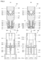
- FIG. FIG. 2 is a cross-sectional view showing a method of connecting the syringe and connector shown in FIG. 1; 4 is an enlarged view of region IV shown in FIG. 3.
- FIG. 4 is an enlarged view of region V shown in FIG. 3.
- FIG. 4 is an enlarged view of region VI shown in FIG. 3.
- FIG. FIG. 2 is a sectional view showing a connected state of the syringe and connector shown in FIG. 1.
- FIG. 8 is an enlarged view of region VIII shown in FIG. 7.
- FIG. 8 is an enlarged view of region IX shown in FIG. 7.
- FIG. 2 is a cross-sectional view for explaining a drug mixing operation in the drug administration device shown in FIG. 1.
- FIG. FIG. 2 is a cross-sectional view for explaining a drug mixing operation in the drug administration device shown in FIG. 1.
- FIG. 12 is an enlarged view of region XII shown in FIG. 11.
- FIG. FIG. 2 is a cross-sectional view for explaining a drug mixing operation in the drug administration device shown in FIG. 1.
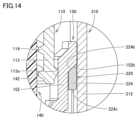
- FIG. 14 is an enlarged view of region XIV shown in FIG. 13.
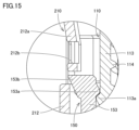
- FIG. 14 is an enlarged view of region XV shown in FIG. 13.
- FIG. 14 is an enlarged view of region XVI shown in FIG. 13.
- FIG. FIG. 2 is a cross-sectional view for explaining a drug mixing operation in the drug administration device shown in FIG. 1.
- FIG. 1 is a cross-sectional view for explaining a drug mixing operation in the drug administration device shown in FIG. 1.
- FIG. 18 is an enlarged view of region XVIII shown in FIG. 17.
- FIG. FIG. 2 is a cross-sectional view for explaining a drug mixing operation in the drug administration device shown in FIG. 1.
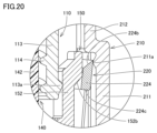
- FIG. 20 is an enlarged view of region XX shown in FIG. 19.
- FIG. 20 is an enlarged view of region XXI shown in FIG. 19.
- FIG. FIG. 2 is a cross-sectional view for explaining a drug mixing operation in the drug administration device shown in FIG. 1.
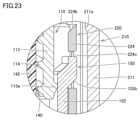
- FIG. 23 is an enlarged view of region XXIII shown in FIG. 22.
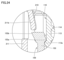
- FIG. 23 is an enlarged view of region XXIV shown in FIG. 22.
- FIG. FIG. 2 is a cross-sectional view for explaining a drug mixing operation in the drug administration device shown in FIG. 1.
- FIG. 2 is a cross-sectional view for explaining a drug mixing operation in the drug administration device shown in FIG. 1.
- FIG. FIG. 2 is a cross-sectional view for explaining a drug mixing operation in the drug administration device shown in FIG. 1.
- FIG. FIG. 2 is a cross-sectional view for explaining a drug mixing operation in the drug administration device shown in FIG. 1.
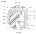
- FIG. 29 is an enlarged view of area XXIX shown in FIG. 28.
- FIG. 29 is an enlarged view of area XXX shown in FIG. 28.
- FIG. FIG. 2 is a cross-sectional view for explaining a drug mixing operation in the drug administration device shown in FIG. 1.
- FIG. 1 is a perspective view of a drug administration device and a vial according to an embodiment. First, with reference to FIG. 1, a schematic configuration of a drug administration device 1 according to the present embodiment will be described.
- a drug administration device 1 As shown in FIG. 1, a drug administration device 1 according to the present embodiment is used for the purpose of administering a drug to a patient etc. after preparing the drug to be administered to the patient etc., and includes a syringe 100 and A connecting tool 200 is provided.
- the syringe 100 and the connector 200 are connected in advance in use, and in this connected state, the vial 300 can be further connected to the connector 200.
- the syringe 100 and the vial 300 are first connected by connecting the vial 300 to the connector 200, and then the drug mixing operation described later is performed, and the drug is mixed with the vial 300. After the mixing operation is completed, the syringe 100 is further removed from the connector 200 and the drug is administered.
- the syringe 100 is configured as a prefilled syringe filled with a liquid first drug 401 (see FIG. 3, etc.) such as distilled water, physiological saline, or glucose solution.
- a second drug 402 such as a dry drug, is sealed in the vial 300.
- the medicine sealed in the vial 300 is not limited to a powder or solid substance such as a dry medicine, but may be a liquid medicine or the like.
- FIG. 2 is an exploded perspective view of the drug administration tool shown in FIG. 1.
- FIG. 3 is a sectional view showing a method of connecting the syringe and connector shown in FIG. 1, and FIGS. 4 to 6 are enlarged views of region IV, region V, and region VI shown in FIG. 3, respectively.
- FIG. 7 is a sectional view showing a connected state of the syringe and the connector shown in FIG. 1, and FIGS. 8 and 9 are enlarged views of region VIII and region IX shown in FIG. 7, respectively.
- FIGS. 2 to 9 the detailed configuration of the drug administration device 1 according to the present embodiment, the connection method between the syringe 100 and the connector 200 in the drug administration device 1, and the connection after the connection. Explain the condition.
- the cross section shown in FIG. 3(A) and the cross section shown in FIG. 3(B) are both cross sections of the drug administration device 1 along a direction parallel to the axial direction of the syringe 100 and the connector 200, These cross sections are mutually orthogonal.
- the cross section shown in FIG. 7(A) is a cross section on the same plane as the cross section shown in FIG. 3(A)
- the cross section shown in FIG. 7(B) is on the same plane as the cross section shown in FIG. 3(B). This is a cross section at the top.
- the syringe 100 includes a barrel 110, a plunger 120, a packing 130, a stopper 140, and a cap 150.
- the barrel 110, plunger 120, packing 130, stopper 140, and cap 150 are assembled in advance, and the first drug 401 is filled into the syringe 100, as described above. , is configured as a prefilled syringe filled with a first drug 401.
- the barrel 110 functions as a container for storing the first medicine 401, and includes a cylindrical portion 111, a nozzle portion 112 located at the front end side of the cylindrical portion 111 in the axial direction, and a cylindrical portion surrounding the nozzle portion 112. , a female screw portion 114 provided on the inner peripheral surface of the surrounding portion 113 , and a finger hook portion 115 located on the rear end side of the cylindrical portion 111 in the axial direction.
- the nozzle part 112 is a part that functions as an outlet through which the medicine is taken out when administering the medicine, and the gap between the nozzle part 112 and the surrounding part 113 is provided with a The needle base is connected.
- the female screw portion 114 provided on the inner circumferential surface of the surrounding portion 113 described above is for fixing this needle hub.
- the finger hook portion 115 is a portion on which the user can easily handle the syringe 100 by placing his or her finger thereon during various operations to be described later. It is located in such a way that it stands out.
- the plunger 120 is made of a rod-shaped member, and is slidably assembled to the barrel 110 by being inserted into the barrel 110 from the rear end side.
- a convex portion 121 is provided at the front end of the plunger 120, and a male screw portion 122 is provided on the outer peripheral surface of this convex portion 121.
- the packing 130 is for liquid-tightly sealing the medicine filled inside the barrel 110 at the rear end side of the barrel 110, and is made of, for example, a rubber member or an elastomer member. ing.
- a concave portion 131 is provided at the rear end of the packing 130, and a female screw portion 132 is provided on the inner peripheral surface of the concave portion 131.
- the convex portion 121 provided at the front end of the plunger 120 is inserted into the concave portion 131 provided at the rear end of the packing 130.
- a male screw portion 122 provided on a convex portion 121 of the plunger 120 is screwed into a female screw portion 132 provided on a concave portion 131 of the packing 130.
- a packing 130 is attached to the front end of the plunger 120.
- the plug body 140 is for liquid-tightly sealing the medicine filled inside the barrel 110 at the front end side of the barrel 110, and is made of, for example, a rubber member or an elastomer member. ing.
- the plug body 140 includes a disc-shaped plug portion 141 and a cylindrical destination portion 142 that stands up from the rear surface of the plug portion 141 .
- the cap 150 is for fixing the stopper 140 to the barrel 110, and has a substantially cylindrical shape with a bottom.
- the cap 150 includes a disc-shaped base 151 having an opening 151a in the center, and a pair of first upright portions 152 and a pair of second upright portions 153 that stand up from the periphery of the base 151.
- the pair of first standing portions 152 and the pair of second standing portions 153 are provided alternately along the circumferential direction of the cap 150, and each of the pair of first standing portions 152 is provided on the cap 150. They are located opposite to each other so as to sandwich the axis, and each of the pair of second upright portions 153 is also located opposite to each other so as to sandwich the axis of the cap 150 .
- plug body 140 and cap 150 are detachably attached to the front end of barrel 110, and the detailed assembly structure will be described later.
- the barrel 110 and plunger 120 described above are both made of resin members manufactured by injection molding or the like.
- the connector 200 includes a connector main body 210 and a movable member 220. As shown in FIG. 3, the connector main body 210 and the movable member 220 are assembled into a unit in advance.
- the connector main body 210 connects the syringe 100 and the vial 300 during a drug mixing operation, and also guides the movement of the movable member 220 disposed therein.
- the connector main body 210 has a generally cylindrical shape and includes a front cylindrical portion 211 and a rear cylindrical portion 212 as cylindrical portions, and a connecting portion 213.
- the front cylindrical portion 211 is provided at the center of the connector body 210 in the axial direction, and the rear cylindrical portion 212 extends rearward from the rear end of the front cylindrical portion 211 .
- the connecting part 213 extends forward from the front end of the front cylinder part 211.
- the front cylinder part 211 and the rear cylinder part 212 are parts into which the syringe 100 is inserted from the rear end of the connector main body 210.
- the inner dimension of the rear cylindrical portion 212 is configured to be smaller than the inner dimension of the front cylindrical portion 211, so that the inner shape of the rear cylindrical portion 212 is smaller than the inner shape of the front cylindrical portion 211. .
- the connecting part 213 is a part for connecting the vial 300 to the connector 200, and has a generally cylindrical shape so that the vial 300 can be received.
- the inner dimension of the connecting portion 213 is configured to be larger than the inner dimension of the front tube portion 211 , so that the inner shape of the connecting portion 213 is larger than the inner shape of the front tube portion 211 .
- the movable member 220 is for communicating the inside of the syringe 100 and the inside of the vial 300 during a drug mixing operation.
- the movable member 220 includes a disc-shaped base 221, a front needle part 222 that projects forward from the center of the front surface of the base 221, and a front needle part 222 that projects rearward from the center of the rear surface of the base 221. It includes a rear needle portion 223 and a pair of upright portions 224 erected from the periphery of the base portion 221 .
- the base 221 supports a front needle part 222, a rear needle part 223, and a pair of upright parts 224, and each of the pair of upright parts 224 is positioned opposite to each other so as to sandwich the rear needle part 223. are doing.
- the front needle part 222 is a part that is pierced by a stopper 320 provided in the vial 300, which will be described later, during a drug mixing operation
- the rear needle part 223 is a part that is inserted into the syringe 100 during a drug mixing operation. This is the part that is pierced by the plug 140.
- a hollow communication passage 225 (see FIG. 3, etc.) is provided in the base 221, the front needle part 222, and the rear needle part 223 so as to pass through them.
- the movable member 220 moves inside the front cylinder part 211 and the rear cylinder part 212 as the cylindrical parts of the connector main body 210.
- the connector body 210 is assembled so as to be movable relative to the connector main body 210, and the detailed assembly structure will be described later.
- the above-mentioned connector main body 210 and movable member 220 are both made of resin members manufactured by injection molding or the like.
- a stopper 140 is attached to the nozzle portion 112 of the barrel 110, and a cap 150 is attached to cover the stopper 140. It is detachably attached to the surrounding part 113 of the barrel 110.
- the plug body 140 has its destination portion 142 inserted into the outside of the nozzle portion 112, and is tightly attached to the nozzle portion 112 so that the plug portion 141 covers the opening located at the front end of the nozzle portion 112. installed. Thereby, the nozzle portion 112 is closed by the stopper 140. Further, the plug body 140 is held by a cap 150, and by attaching the cap 150 to the surrounding portion 113 of the barrel 110, the plug body 140 is prevented from falling off from the nozzle portion 112.
- an engagement protrusion 153a is provided at a predetermined position on the inner surface of the second upright portion 153 of the cap 150.
- an engaging protrusion 113a provided at a predetermined position on the outer peripheral surface of the surrounding portion 113 of the barrel 110 is engaged.
- These engaging protrusions 153a, 113a are mutually connected to each other by elastically deforming, especially in such a manner that the second upright portion 153 of the cap 150 is bent outward when the cap 150 is inserted or removed along the axial direction of the barrel 110. You will get through it.
- the cap 150 can be attached to and detached from the barrel 110, and when the cap 150 is attached to the barrel 110 (that is, the state shown in FIG. 3), the cap 150 can be attached to and detached from the barrel 110. 110, it will be lightly held.
- a locking pawl 152a is provided at a predetermined position on the inner surface of the first upright portion 152 of the cap 150.
- This locking pawl 152a holds the periphery of the plug portion 141 of the plug body 140 by sandwiching it between the locking claw 152a and the base portion 151 of the cap 150.
- the front surface of the locking pawl 152a is configured with a surface parallel to the front surface of the cap 150, while the rear surface of the locking pawl 152a is configured with an inclined surface that slopes forward toward the inner edge. ing.
- the portion of the plug portion 141 that comes into contact with the locking claw 152a is elastically deformed inward, so that the locking claw 152a is
- the plug part 141 can be fitted between the locking pawl 152a and the base 151 by climbing over the cap 150, so that the plug body 140 can be held by the cap 150. Therefore, the stopper 140 can be prevented from easily falling off from the cap 150.
- the movable member 220 is inserted into the front cylindrical part 211 and the rear cylindrical part 212 as cylindrical parts of the connector main body 210. Furthermore, the movable member 220 is lightly held on the connector main body 210 by a first holding mechanism described later.
- an engagement protrusion 224a is provided at a predetermined position on the outer surface of the upright portion 224 of the movable member 220.
- An engaging protrusion 211a provided at a predetermined position on the inner circumferential surface of the front cylindrical portion 211 of the connector body 210 engages with the engaging protrusion 211a.
- the engaging protrusion 224a is fitted into the gap between this stepped portion and the above-mentioned engaging protrusion 211a. That is, these engaging protrusions 224a and 211a correspond to a first holding mechanism that lightly holds the movable member 220 on the connector main body 210.
- the engagement protrusion 224a is elastically deformed such that the upright portion 224 is bent inward, so that the engagement protrusion 224a can be moved over the engagement protrusion 211a. become.
- the front end of the syringe 100 when connecting the syringe 100 to the connector 200, the front end of the syringe 100 is positioned while circumferentially positioning the syringe 100 (more precisely, positioning the cap 150 in the circumferential direction). , is inserted into the interior of the connector main body 210 from the rear end side of the connector main body 210 along the arrow DR1 direction shown in the figure. Thereby, as shown in FIG. 7, the front end of the syringe 100 is placed inside the rear cylinder part 212 of the connector main body 210.
- the outer surfaces of the first erected portion 152 and the second erected portion 153 of the cap 150 and the outer circumferential surface of the barrel 110 are guided by the inner circumferential surface of the rear cylindrical portion 212 of the connector main body 210. This allows the front end of the syringe 100 to be smoothly guided into the connector main body 210.
- the cap 150 is lightly held on the connector main body 210 by a second holding mechanism, which will be described later.
- a locking protrusion 153b is provided at a predetermined position on the outer surface of the second upright portion 153 of the cap 150, and a locking protrusion 153b is provided at a predetermined position on the outer surface of the second upright portion 153 of the cap 150.
- a tongue-shaped locking plate 212a having a locking hole 212b at its tip is provided at a predetermined position.
- These locking projections 153b and locking holes 212b are provided in correspondence with each other, and when the front end of the syringe 100 is inserted into the rear cylinder portion 212 by a predetermined amount, the locking projections 153b are inserted into the locking plate 212a. and fits into the locking hole 212b. Thereby, the cap 150 is easily held on the connector main body 210.
- the locking protrusion 153b is configured with an inclined surface whose outer surface protrudes outward as it goes rearward, so that the front end of the syringe 100 is inserted into the rear cylinder part 212 of the connector main body 210.
- the rear surface of the inner surface of the locking hole 212b is configured with a surface parallel to the rear surface of the locking protrusion 153b.
- the cap 150 is easily held on the connector main body 210 by the second holding mechanism consisting of the locking protrusion 153b, the locking plate 212a, and the locking hole 212b.
- the syringe 100 is inserted into the rear cylindrical portion 212 of the connector main body 210 by a predetermined amount, and a state in which the syringe 100 is held by the connector 200 can be realized.
- the stopper 140 In a state in which the front end of the syringe 100 is inserted into the rear cylinder part 212 of the connector main body 210 by this predetermined amount (that is, in a state in which the cap 150 is lightly held by the second holding mechanism), the stopper 140 The position where is placed is defined as the first position. A state in which the stopper 140 is placed in the first position is a connected state in which the syringe 100 is connected to the connector 200.
- the first contact surface 224b provided on the upright portion 224 of the movable member 220 and the first contact surface 224b of the cap 150 are arranged to face each other.
- first contact surface 224b is provided at the rear end of the upright portion 224 of the movable member 220, and the outer edge of the first contact surface 224b is located on the rear end side of the connector 200.
- the inner edge thereof is configured to have an inclined shape located on the front end side of the connector 200.
- the second contact surface 152b is provided at a predetermined position on the outer surface of the first upright portion 152 of the cap 150, and the outer edge of the second contact surface 152b is on the rear end side of the connector 200.
- the connector 200 has an inclined shape with an inner edge located on the front end side of the connector 200.
- the tip of the rear needle part 223 of the movable member 220 is connected to the opening 151a provided in the base 151 of the cap 150.
- the movable member 220 is positioned opposite the plug body 140.
- the syringe 100 is connected to the connector 200 in advance in the pre-medication mixing operation, and in this state, The drug administration device 1 and the vial 300 are provided to the user as a set.
- FIG. 10, FIG. 11, FIG. 13, FIG. 17, FIG. 19, FIG. 22, FIG. 25 to FIG. 28, and FIG. 31 are cross-sectional views for explaining the drug mixing operation in the drug administration device according to the present embodiment.
- . 12 and 13 are enlarged views of region XII and region XIII shown in FIG. 11, and FIGS. 14 to 16 are enlarged views of region XIV, region XV, and region XVI shown in FIG. 13.
- 18 is an enlarged view of region XVIII shown in FIG. 17, and FIGS. 20 and 21 are enlarged views of region XX and region XXI shown in FIG. 19.
- FIGS. 23 and 24 are enlarged views of area XXIII and area XXIV shown in FIG. 22, and FIGS.
- the cross sections shown in FIG. 31 are all cross sections on the same plane as the cross section shown in FIG. 3(A), and are shown in FIG. 10(B), FIG. 11(B), FIG.
- the cross sections shown in FIG. 19(B), FIG. 22(B), and FIG. 28(B) are all cross sections on the same plane as the cross section shown in FIG. 3(B).
- a vial 300 is first connected to a connector 200 to which a syringe 100 is connected.
- the connecting part 213 of the connector 200 to which the syringe 100 is connected is arranged so as to be located above the vial 300, and in this state, the connector 200 is oriented in the direction of arrow DR2 in the figure with respect to the vial 300.
- the vial 300 is connected to the connector 200 by being placed over the connector 200.
- the vial 300 has a container body 310, a stopper 320, and a sealing member 330, and the second drug 402 is sealed inside the vial 300 as described above.
- a stopper 320 is attached to the container body 310 so as to close the mouth 311 of the container body 310, and a sealing member 330 connects the stopper 320 and the mouth of the container body 310.
- the sealing member 330 has an opening 331 at a position corresponding to the center of the plug 320, so that the center of the plug 320 is exposed to the outside.
- an engaging protrusion 213a is provided at a predetermined position on the inner surface of the connecting portion 213 of the connector main body 210, and when the vial 300 is connected to the connector 200, , this engaging protrusion 213a engages with the flange-shaped opening 311 of the vial 300.
- the engagement protrusion 213a elastically deforms when the vial 300 is inserted into the connection part 213 of the connector main body 210, so that the connection part 213 provided with the engagement protrusion 213a is bent outward, so that the vial 300 and gets over the mouth part 311.
- a step portion formed by the inner shape of the front cylinder portion 211 being smaller than the inner shape of the connecting portion 213 is located at the rear position of the engagement protrusion 213a, and the step portion is formed by making the inner shape of the front cylinder portion 211 smaller than the inner shape of the connecting portion 213.
- the mouth portion 311 of the connector 300 is held by the connector main body 210 by fitting into the gap between this stepped portion and the above-mentioned engaging protrusion 213a.
- the portion of the vial 300 where the stopper 320 is exposed is located opposite the front needle portion 222 of the movable member 220. Note that when connecting the vial 300 to the connector 200, the syringe 100 and the movable member 220 do not move relative to the connector main body 210, and the stopper 140 of the syringe 100 remains in the first position described above. It remains in the state where it was placed.
- the syringe 100 is moved toward the front end of the connector body 210 (that is, in the direction of arrow DR3 shown in FIG. 11).
- the user holds, for example, the cylindrical portion 111 of the barrel 110 and the finger hook portion 115 and performs the operation.
- the cap 150 of the syringe 100 moves toward the front end of the connector main body 210, and as a result, the first upright portion 152 of the cap 150 moves.
- the provided second contact surface 152b comes into contact with the first contact surface 224b provided on the upright portion 224 of the movable member 220.
- the movable member 220 is pushed down by the cap 150, and the movable member 220 moves toward the front end of the connector main body 210. I will do it.
- the upright portion 224 is located inside the rear cylindrical portion 212, which has an inner shape smaller than the inner shape of the front cylindrical portion 211, outward deformation of the upright portion 224 is prevented. It is regulated by the rear cylinder part 212. Therefore, the state in which the second contact surface 152b is in contact with the first contact surface 224b is maintained, and the movable member 220 is interlocked with the movement of the cap 150 toward the front end side of the connector main body 210. Then, it moves toward the front end side of the connector main body 210.
- the locking protrusion 153b provided on the second upright portion 153 of the cap 150 moves as shown in FIGS. 13 and 15.
- the locking plate 212a provided on the rear cylindrical portion 212 is pushed down toward the outside, thereby detaching from the locking hole 212b provided in the locking plate 212a.
- the outer surface of the locking protrusion 153b has an inclined surface that protrudes outward as it goes rearward, the cap 150 smoothly moves toward the front end side of the connector main body 210.
- the front needle portion 222 of the movable member 220 also moves to the front end of the connector body 210. As it moves toward the side, the tip of the front needle portion 222 is pressed against the stopper 320 of the vial 300. As a result, piercing of the front needle portion 222 into the stopper 320 of the vial 300 is started.
- the syringe 100 is further moved toward the front end of the connector main body 210 in the direction of arrow DR3 shown in the drawing, so that the front needle portion 222 is attached to the vial 300 as shown in FIG. Completely pierce the stopper 320.
- the tip of the front needle portion 222 reaches the inside of the vial 300, and the communication path 225 provided in the movable member 220 communicates with the inside of the vial 300.
- the movement of the movable member 220 toward the front end side of the connector body 210 is stopped when the base 221 of the movable member 220 comes into contact with the vial 300.
- the position of the stopper 140 when the movable member 220 stops is defined as a second position.
- the second contact surface 152b provided on the first upright portion 152 of the cap 150 The state in which it is in contact with the first contact surface 224b provided on the upright portion 224 is maintained. However, at this time, the portion where the first abutting surface 224b and the second abutting surface 152b abut passes through the rear cylindrical portion 212 and has an inner shape larger than that of the rear cylindrical portion 212. It reaches the constructed front cylinder part 211.
- the syringe 100 is further moved from the state shown in FIG. 17 toward the front end side of the connector main body 210 in the direction of arrow DR3 shown in the drawing, as shown in FIGS. 19 and 20.
- the upright portion 224 is elastically deformed outward so as to ride on the first upright portion 152 at a portion located closer to the rear end of the connector main body 210 than the portion where the second contact surface 152b is provided.
- the syringe 100 continues to move toward the front end of the connector main body 210 while the movable member 220 remains stopped.
- the upright portion 224 passes through the rear cylindrical portion 212 , which has an inner shape smaller than that of the front cylindrical portion 211 , and has an inner shape larger than the inner shape of the rear cylindrical portion 212 .
- the upright part 224 is allowed to deform outward. Therefore, as a result, the state in which the second contact surface 152b is in contact with the first contact surface 224b is released, and the upright portion 224 rides on the first upright portion 152 as described above.
- the movable member 220 stops without being interlocked with the movement of the syringe 100 toward the front end of the connector main body 210.
- the locking protrusion 153b provided on the second upright portion 153 of the cap 150 is connected to the tongue provided on the front cylinder portion 211 of the connector body 210.
- the locking protrusion 153b comes into contact with the piece-shaped locking plate 211b, but as described above, the locking protrusion 153b has an inclined surface that protrudes outward as the outer surface goes rearward, so that the syringe 100 As it moves toward the front end side of the connector main body 210, the locking plate 211b is pushed down toward the outside, thereby causing the locking protrusion 153b to pass through the locking plate 211b. Therefore, the syringe 100 continues to move toward the front end side of the connector main body 210 without being hindered in its movement.
- the stopper 140 of the syringe 100 also moves toward the front end of the connector body 210, as shown in FIG. As a result, the tip of the rear needle portion 223 is pressed against the stopper 140. As a result, piercing of the rear needle portion 223 into the stopper 140 of the syringe 100 is started.
- the syringe 100 is further moved toward the front end of the connector main body 210 in the direction of arrow DR3 shown in the drawing, so that the rear needle portion 223 is moved toward the syringe as shown in FIG. 100 plugs 140 are completely pierced.
- the tip of the rear needle portion 223 reaches the inside of the syringe 100, and the communication path 225 provided in the movable member 220 communicates with the inside of the syringe 100. Accordingly, the inside of the syringe 100 and the inside of the vial 300 are brought into communication via the communication path 225.
- the movement of the syringe 100 toward the front end side of the connector main body 210 is stopped when the base 151 of the cap 150 comes into contact with the base 221 of the movable member 220, which has stopped previously.
- the position of the stopper 140 when the syringe 100 stops is defined as a third position.
- the locking protrusion 153b provided on the second upright portion 153 of the cap 150 is connected to the tongue provided on the front cylinder portion 211 of the connector body 210. It passes through a piece-shaped locking plate 211b and is arranged closer to the front end of the connector main body 210 than the locking plate 211b. Accordingly, the contact between the locking protrusion 153b and the locking plate 211b is also released, and the above-described elastic deformation of the locking plate 211b toward the outside is also released.
- the locking plate 211b When the locking plate 211b returns to its original position as the elastic deformation toward the outside of the locking plate 211b is released, the locking plate 211b locks along the axial direction of the connector main body 210. It will be placed behind the protrusion 153b. Therefore, the locking plate 211b becomes a so-called barb, and the cap 150 does not easily move toward the rear of the connector main body 210, and the cap 150 is fixed to the connector main body 210. .
- the syringe 100 is moved toward the front end side of the connector body 210.
- the stopper 140 moves from a first position (i.e., the position shown in FIG. 11) that is closer to the rear end of the connector body 210 to a position closer to the front end of the connector body 210 than the first position.
- the second position i.e., the position shown in FIG. 17
- the third position i.e., the position shown in FIG. 22
- the rear needle portion 223 of the movable member 220 is arranged in advance so as to face the plug 140 when the plug 140 is placed in the first position.
- the movable member 220 can be in an interlocked state in which it moves toward the front end of the connector body 210 in conjunction with the movement of the connector body 210 of the syringe 100 toward the front end, and in an interlocked state in which it moves toward the front end of the connector body 210 of the syringe 100 .
- the movable member 220 is configured to be able to switch to a non-interlocking state in which it stops without interlocking movement toward the front end side, and this switching is possible when the first contact surface 224b provided on the movable member 220 and the cap 150 are provided. This is realized by an interlocking/non-interlocking switching mechanism constituted by the second contact surface 152b, the front cylindrical portion 211 and the rear cylindrical portion 212 of the connector main body 210.
- the movable member 220 is moved to the front end side of the connector main body 210 while the rear needle portion 223 is maintained in a position facing the plug body 140.
- the interlocking/non-interlocking switching mechanism As a result, the stopper 140 moves toward the front end of the connector main body 210 while the movable member 220 is maintained in a stopped state, so that the rear needle portion 223 is moved to the stopper 140. It is configured to be pierced.
- the front needle portion 222 connects the vial at the beginning of the movement of the syringe 100 toward the front end of the connector body 210 described above.
- the plug 320 of the syringe 100 is pierced, and then, at the end of the movement of the syringe 100 toward the front end of the connector main body 210, the plug 140 of the syringe 100 is pierced by the rear needle portion 223. You can make it happen. That is, after the front needle part 222 completes piercing the stopper 320 of the vial 300, the rear needle part 223 can start piercing the stopper 140 of the syringe 100.
- the rear needle part 223 starts piercing the stopper 140 of the syringe 100, it means that the front needle part 222 has already completed piercing the stopper 320 of the vial 300. Even if the user accidentally presses down the plunger 120 of the syringe 100 before the side needle part 223 completes piercing the stopper 140 of the syringe 100, the first drug 401 will not leak inside the connector 200. can definitely be prevented.
- the plunger 120 is pressed down from the state shown in FIG. 22 along the direction of the arrow DR4 shown in the figure.
- the first drug 401 filled inside the syringe 100 is led out to the vial 300 via the communication path 225 provided in the movable member 220.
- the first medicine 401 and the second medicine 402 are mixed inside the vial 300.
- first drug 401 and second drug 402 are suspended by swinging vial 300 in the direction of arrow DR5 shown in the figure.
- the syringe 100 and the vial 300 connected by the connector 200 are integrally turned upside down in the direction of the arrow DR6 shown in the figure, so that the state shown in FIG. 26 is achieved. be done.
- the plunger 120 is pulled down in the direction of arrow DR7 shown in the figure.
- the mixed drug 403 that is, the drug after being suspended with the first drug 401 and the second drug 402 contained in the vial 300 is provided on the movable member 220. It is introduced into the syringe 100 via the communication path 225.
- the syringe 100 is pulled out from the connector 200 from the state shown in FIG. 27 in the direction of arrow DR8 shown in the figure.
- the user holds, for example, the cylindrical portion 111 of the barrel 110 and the finger hook portion 115 and performs the operation.
- the locking plate 211b provided on the front cylindrical portion 211 of the connector main body 210 functions as the above-mentioned so-called return. Therefore, when the locking protrusion 153b provided on the second upright portion 153 of the cap 150 comes into contact with the locking plate 211b, the cap 150 is fixed to the connector main body 210, and the locking plate 211b of the cap 150 is fixed. Movement toward the rear will be restricted. That is, the locking plate 211b and the locking protrusion 153b function as a locking mechanism that makes it impossible for the cap 150 to move toward the rear end side of the connector main body 210.
- the plug 140 is held between the locking pawl 152a provided on the first upright portion 152 of the cap 150 and the base 151 of the cap 150, as described above. Since the plug part 141 is held in place, the plug body 140 is removed from the barrel 110 together with the cap 150.
- the drug mixing operation using the drug administration device 1 according to the present embodiment is completed, and after that, the needle base is attached to the nozzle portion 112 and the surrounding portion 113 of the syringe 100, and the drug administration device 1 according to the present embodiment is attached to the nozzle portion 112 and the surrounding portion 113 of the syringe 100.
- Administration (ie, injection) of the drug is performed.
- the interlocking/non-interlocking of the movable member 220 with respect to the syringe 100 is performed at a predetermined timing. Since the first medicine 401 is configured to be switched by the user, it is possible to reliably prevent the first medicine 401 from leaking inside the connector 200 even if the user makes a mistake in operation.
- the stopper 320 of the vial 300 It is also possible to prevent problems such as the front needle part 222 being inserted diagonally into the plug 140 of the syringe 100 or the rear needle part 223 being inserted diagonally into the stopper 140 of the syringe 100.
- the drug administration device 1 it is possible to determine whether or not a predetermined step in the connection operation between the syringe 100 and the vial 300 is completed by a click feeling or visual confirmation from the outside. Since this can be confirmed, the front needle part 222 may not be sufficiently penetrated into the stopper 320 of the vial 300, or the rear needle part 223 may not be sufficiently penetrated into the stopper 140 of the syringe 100. It is also possible to prevent problems such as
- the drug administration device 1 by using the drug administration device 1 according to the present embodiment, it is possible to obtain a drug administration device that is extremely easy to use and prevents various malfunctions from occurring.
- the configuration of the front end side of the syringe 100 can also be simplified. That is, in the drug administration devices as disclosed in Patent Documents 1 and 2 mentioned above, in order to connect and release the connection between the coupling device and the syringe, a female is provided on the inner circumferential surface of the surrounding portion provided so as to surround the nozzle portion. Not only is a threaded portion provided, but also a male threaded portion is provided on the outer peripheral surface of the surrounding portion. However, in the drug administration device 1 according to the present embodiment, there is no need to provide such a male threaded portion on the outer peripheral surface of the surrounding portion 113. Therefore, by using the drug administration device 1 according to the present embodiment, the configuration is simplified compared to the conventional one, so that it is also possible to provide the drug administration device at a low cost.
- the characteristic configuration of the drug administration device 1 according to the present embodiment described above can be summarized as follows.
- a drug administration device comprising: a connector for connecting the syringe to a vial containing a second drug, in order to mix the first drug with a second drug different from the first drug;
- the above syringe is a barrel including a nozzle portion and a surrounding portion surrounding the nozzle portion at the front end; a plunger inserted into the barrel from the rear end side of the barrel; a plug that closes the nozzle part; a cap that holds the stopper and is detachably attached to the surrounding portion;
- the above connector is a connector main body having a connecting part for connecting a vial at the front end, and a cylindrical part into which the syringe is inserted at a position closer to the rear end than the connecting part; It includes a front needle part that pierces the vial and a rear needle part that can pierce the stopper, and is arranged relative to the connector body so that it can move inside the cylindrical part.
- the drug administration device further comprises an interlocking/non-interlocking switching mechanism that switches to a non-interlocking state in which the movable member stops without interlocking with movement toward the target.
- the syringe moves from a first position in which the stopper is closer to the rear end of the connector body to a second position that is closer to the front end of the connector body than the first position. connected to the connector so as to be movable toward the front end of the connector body so as to be disposed at a third position that is closer to the front end of the connector body than the second position;
- the movable member is arranged in advance so that the rear needle portion is positioned opposite to the plug when the plug is in the first position;
- the movable member moves toward the front end side of the connector main body while the rear needle portion remains positioned opposite to the plug body, and the plug body moves toward the front end side of the connector main body.
- the rear needle portion is configured to pierce the plug body by moving the plug body toward the front end of the connector main body while the movable member is maintained in a stopped state.
- the movable member has a base that supports the front needle part and the rear needle part, and is erected from the periphery of the base toward the rear end of the connector body, and has an outer edge of the connector body.
- an upstanding portion provided with a first contact surface having an inclined shape and located on the rear end side and having an inner edge located on the front end side of the connector;
- the cap is provided opposite to the first contact surface, and has an inclined second contact surface having an outer edge located on the rear end side of the connector main body and an inner edge located on the front end side of the connector body.
- the cylindrical part includes a front cylindrical part located on the connection part side, and a rear cylindrical part located on the rear end side of the front cylindrical part and having an inner shape smaller than the inner shape of the front cylindrical part.
- the interlocking/non-interlocking switching mechanism includes the first contact surface, the second contact surface, the front cylinder part, and the rear cylinder part, Since the upright portion is located inside the rear cylindrical portion, outward deformation of the upright portion is restricted by the rear cylindrical portion, so that the second contact surface 1
- the above interlocking state is realized by maintaining the state of contact with the contact surface,
- the upright part passes through the inside of the rear cylinder part and is located inside the front cylinder part, allowing outward deformation of the upright part, so that the second abutting part
- the drug administration device according to supplementary note 2, wherein the non-interlocking state is realized by releasing the state in which the surface is in contact with the first contact surface.
- a locking mechanism that fixes the cap to the connector body to prevent the cap from moving toward the rear end of the connector body when the plug body is placed in the third position. Furthermore, By fixing the cap to the connector main body by the locking mechanism, by moving the syringe toward the rear end of the connector main body, the cap and the stopper are removed.
- the interlocking/non-interlocking switching mechanism includes a first contact surface provided on the movable member, a second contact surface provided on the cap, and a second contact surface provided on the connector body.
- the number, shape, arrangement position, etc. of each part described in the embodiment of the present invention described above can be changed as appropriate without departing from the spirit of the present invention.
- various operations included in the chemical liquid mixing operation can also be changed as appropriate.
- the operation when connecting a syringe or vial to a coupling device may be performed by screwing it in instead of simply inserting it, or the operation when removing a syringe from a coupling device may be performed by rotating it and pulling it out instead of simply pulling it out. Good too.
- 1 Drug administration device 100 Syringe, 110 Barrel, 111 Cylindrical part, 112 Nozzle part, 113 Surrounding part, 113a Engaging protrusion, 114 Female thread part, 115 Finger hook part, 120 Plunger, 121 Convex part, 122 Male thread part , 130 Packing, 131 Concave part, 132 Female screw part, 140 Plug body, 141 Plug part, 142 Addressing part, 150 Cap, 151 Base part, 151a Opening part, 152 First standing part, 152a Locking claw, 152b No.
Abstract
薬剤投与具は、栓体(140)を含むシリンジ(100)と、連結具(200)とを備える。連結具(200)は、連結具本体(210)と、前側針部(222)および後側針部(223)を含み、連結具本体(210)に対して相対的に移動可能に組付けられた可動部材(220)とを有する。シリンジは(100)は、連結具本体(210)の前端側に向けて移動可能に連結具(200)に接続される。薬剤投与具には、シリンジ(100)の連結具本体(210)の前端側に向けての移動に連動して可動部材(220)が連結具本体(210)の前端側に向けて移動する連動状態と、シリンジ(100)の連結具本体(210)の前端側に向けての移動に連動せずに可動部材(220)が停止する非連動状態とに切り替える連動/非連動切替機構が設けられる。
Description
本発明は、シリンジと、当該シリンジをバイアルに連結するための連結具とを備えた薬剤投与具に関する。
従来、患者等に投与する薬剤を調製する目的で、蒸留水や生理食塩水、ブドウ糖液等の液剤が充填されたシリンジと、乾燥薬剤等が封入されたバイアルとを連結する連結具が知られている。薬剤の調製を容易化する観点から、通常は、予め液剤が充填されたプレフィルドシリンジと、連結具と、乾燥薬剤等が封入されたバイアルとが、セットとして準備され、薬剤の投与に際しては、これらが相互に接続されて薬剤の混合(溶解・懸濁等)が行なわれる。
この種の薬剤投与具が開示された文献としては、たとえば国際公開第2011/007760号公報(特許文献1)や国際公開第2014/091912号公報(特許文献2)がある。これら特許文献1,2に開示された薬剤投与具においては、シリンジに設けられた栓体を刺通する穿刺針とバイアルに設けられた栓体を刺通する穿刺針とを含む双頭針が連結具に設けられ、連結具によってシリンジとバイアルとが連結された状態において、この双頭針によってシリンジの内部とバイアルの内部とが連通させられることにより、薬剤の混合が可能に構成されている。
上述した薬剤投与具を用いて薬剤の混合を行なう際には、連結具の内部において薬剤が漏れ出すといった不具合が発生することを未然に防止することが必要である。この点、上記特許文献1,2に開示の薬剤投与具においても、予め定められた正しい操作方法に従ってその使用が行なわれれば、そのような問題は発生しない。しかしながら、誤った操作が行なわれてしまった場合(たとえば、シリンジ側へ穿刺針が刺通された状態であってかつバイアル側への穿刺針の刺し込みが不十分な状態でシリンジのプランジャが押下された場合等)においては、連結具の内部において薬剤が漏れ出してしまうおそれもある。
したがって、本発明は、上述した問題に鑑みてなされたものであり、連結具の内部において薬剤が漏れ出すことが確実に防止できる薬剤投与具を提供することを目的とする。
本発明に基づく薬剤投与具は、第1薬剤が充填されたシリンジと、上記第1薬剤を当該第1薬剤とは異なる第2薬剤に混合するために、上記シリンジを第2薬剤が封入されたバイアルに連結するための連結具とを備えたものである。上記シリンジは、ノズル部、および、当該ノズル部を取り囲む囲繞部が前端に設けられたバレルと、上記バレルに当該バレルの後端側から挿し込まれたプランジャと、上記ノズル部を閉塞する栓体と、上記栓体を保持するとともに上記囲繞部に着脱自在に取付けられたキャップとを有している。上記連結具は、バイアルの接続のための接続部が前端に設けられるとともに、上記シリンジが挿し込まれた筒状部が上記接続部よりも後端側の位置に設けられた連結具本体と、バイアルに刺通される前側針部、および、上記栓体に刺通可能な後側針部を含み、上記筒状部の内部を移動することができるように、上記連結具本体に対して相対的に移動可能に組付けられた可動部材とを有している。上記シリンジは、上記連結具本体の前端側に向けて移動可能に上記連結具に接続されている。上記本発明に基づく薬剤投与具は、さらに、上記シリンジの上記連結具本体の前端側に向けての移動に連動して上記可動部材が上記連結具本体の前端側に向けて移動する連動状態と、上記シリンジの上記連結具本体の前端側に向けての移動に連動せずに上記可動部材が停止する非連動状態とに切り替える連動/非連動切替機構を備えている。
本発明によれば、連結具の内部において薬剤が漏れ出すことが確実に防止できる薬剤投与具とすることができる。
以下、本発明の実施の形態について、図を参照して詳細に説明する。なお、以下に示す実施の形態においては、同一のまたは共通する部分について図中同一の符号を付し、その説明は繰り返さない。
図1は、実施の形態に係る薬剤投与具ならびにバイアルの斜視図である。まず、この図1を参照して、本実施の形態に係る薬剤投与具1の概略的な構成について説明する。
図1に示すように、本実施の形態に係る薬剤投与具1は、患者等に投与する薬剤を調製した後に患者等に対して薬剤を投与する目的で使用されるものであり、シリンジ100と連結具200とを備えている。これらシリンジ100および連結具200は、使用に際して予め接続された接続状態とされており、この接続状態において、さらに連結具200にバイアル300が接続可能に構成されている。
薬剤投与具1の使用に際しては、まず、連結具200にバイアル300が接続されることでシリンジ100とバイアル300の連結が行なわれ、その後に後述する薬剤混合操作が行なわることになり、この薬剤混合操作が完了した後には、さらに連結具200からシリンジ100が取り外されて薬剤の投与が行なわれる。
シリンジ100は、予めこれに蒸留水や生理食塩水、ブドウ糖液等の液状の第1薬剤401(図3等参照)が充填されたプレフィルドシリンジとして構成されている。一方、バイアル300には、たとえば乾燥薬剤等の第2薬剤402(図10等参照)が封入されている。なお、バイアル300に封入された薬剤は、乾燥薬剤等の粉体あるいは固形物等に限られず、液剤等であってよい。
図2は、図1に示す薬剤投与具の分解斜視図である。図3は、図1に示すシリンジおよび連結具の接続方法を示す断面図であり、図4ないし図6は、それぞれ図3中に示す領域IV、領域Vおよび領域VIの拡大図である。また、図7は、図1に示すシリンジおよび連結具の接続状態を示す断面図であり、図8および図9は、それぞれ図7中に示す領域VIIIおよび領域IXの拡大図である。次に、これら図2ないし図9を参照して、本実施の形態に係る薬剤投与具1の詳細な構成および当該薬剤投与具1におけるシリンジ100と連結具200との接続方法ならびに接続後の接続状態について説明する。
ここで、図3(A)において示す断面および図3(B)において示す断面は、いずれもシリンジ100および連結具200の軸方向と平行な方向に沿った薬剤投与具1の断面であるが、これら断面は、相互に直交している。また、図7(A)に示す断面は、図3(A)に示す断面と同一平面上における断面であり、図7(B)に示す断面は、図3(B)に示す断面と同一平面上における断面である。
図2および図3に示すように、シリンジ100は、バレル110と、プランジャ120と、パッキン130と、栓体140と、キャップ150とを有している。図3に示すように、これらバレル110、プランジャ120、パッキン130、栓体140およびキャップ150が予め組み立てられ、さらにこれに第1薬剤401が充填されることにより、上述したように、シリンジ100は、第1薬剤401が充填されたプレフィルドシリンジとして構成されている。
バレル110は、第1薬剤401を収容する容器として機能するものであり、筒状部111と、筒状部111の軸方向の前端側に位置するノズル部112と、ノズル部112を取り囲む筒状の囲繞部113と、囲繞部113の内周面に設けられた雌ネジ部114と、筒状部111の軸方向の後端側に位置する指掛け部115とを含んでいる。
このうち、ノズル部112は、薬剤の投与の際に薬剤が導出される導出口として機能する部位であり、当該ノズル部112と囲繞部113との間の隙間には、薬剤の投与の際に針基が接続される。上述した囲繞部113の内周面に設けられた雌ネジ部114は、この針基を固定するためのものである。一方、指掛け部115は、シリンジ100に対して行なう後述する各種の操作の際に使用者が指を掛けることでその取り扱いを容易にするための部位であり、筒状部111から外側に向けて突出するように位置している。
プランジャ120は、棒状の部材からなり、バレル110に当該バレル110の後端側から挿し込まれることでバレル110に対して摺動自在に組付けられている。プランジャ120の前端には、凸状部121が設けられており、この凸状部121の外周面には、雄ネジ部122が設けられている。
パッキン130は、バレル110の内部に充填された薬剤を当該バレル110の後端側の部分において液密に封止するためのものであり、たとえばゴム製の部材やエラストマ製の部材にて構成されている。パッキン130の後端には、凹状部131が設けられており、この凹状部131の内周面には、雌ネジ部132が設けられている。
シリンジ100が組み立てられた状態(すなわち、図3に示す状態)においては、プランジャ120の前端に設けられた凸状部121が、パッキン130の後端に設けられた凹状部131に挿入されており、プランジャ120の凸状部121に設けられた雄ネジ部122が、パッキン130の凹状部131に設けられた雌ネジ部132に螺合している。これにより、プランジャ120の前端には、パッキン130が取付けられている。このように構成することにより、バレル110に対するプランジャ120の挿し込み量が増減することにより、シリンジ100からの上述した薬剤の導出や後述する薬剤の導入が行なわれることになる。
栓体140は、バレル110の内部に充填された薬剤を当該バレル110の前端側の部分において液密に封止するためのものであり、たとえばゴム製の部材やエラストマ製の部材にて構成されている。栓体140は、円盤状の栓部141と、当該栓部141の後面から立設された筒状の宛がい部142とを含んでいる。
キャップ150は、栓体140をバレル110に固定するためのものであり、略有底筒状の形状を有している。キャップ150は、中央に開口部151aが設けられた円盤状の基部151と、基部151の周縁から立設された一対の第1立設部152および一対の第2立設部153とを含んでいる。一対の第1立設部152と一対の第2立設部153とは、キャップ150の周方向に沿って交互に設けられており、一対の第1立設部152の各々は、キャップ150の軸線を挟むように対向して位置しており、一対の第2立設部153の各々も、キャップ150の軸線を挟むように対向して位置している。
これら栓体140およびキャップ150は、バレル110の前端に着脱自在に取付けられるものであるが、その詳細な組付構造については、後述することとする。なお、上述したバレル110およびプランジャ120は、いずれもたとえば射出成形等によって製作された樹脂製の部材にて構成される。
図2および図3に示すように、連結具200は、連結具本体210と、可動部材220とを有している。図3に示すように、これら連結具本体210および可動部材220は、予め組み立てられることでユニット化されている。
連結具本体210は、薬剤混合操作の際に、シリンジ100とバイアル300とを連結させるとともに、その内部に配置された可動部材220の移動を案内するものである。連結具本体210は、概ね筒状の形状を有しており、筒状部としての前側筒部211および後側筒部212と、接続部213とを含んでいる。前側筒部211は、連結具本体210の軸方向の中央位置に設けられており、後側筒部212は、当該前側筒部211の後端から後方に向けて延設されている。一方、接続部213は、前側筒部211の前端から前方に向けて延設されている。
前側筒部211および後側筒部212は、連結具本体210の後端からシリンジ100が挿入される部位である。後側筒部212の内側寸法は、前側筒部211の内側寸法よりも小さく構成されており、これにより後側筒部212の内形は、前側筒部211の内形よりも小さくなっている。
一方、接続部213は、連結具200にバイアル300を接続するための部位であり、バイアル300が受け入れ可能となるように概ね筒状の形状を有している。接続部213の内側寸法は、前側筒部211の内側寸法よりも大きく構成されており、これにより接続部213の内形は、前側筒部211の内形よりも大きくなっている。
可動部材220は、薬剤混合操作の際に、シリンジ100の内部とバイアル300の内部とを連通させるためのものである。可動部材220は、円盤状の基部221と、基部221の前面の中央部から前方に向けて突設された前側針部222と、基部221の後面の中央部から後方に向けて突設された後側針部223と、基部221の周縁から立設された一対の立設部224とを含んでいる。基部221は、前側針部222、後側針部223および一対の立設部224を支持しており、一対の立設部224の各々は、後側針部223を挟むように対向して位置している。
前側針部222は、薬剤混合操作の際に、バイアル300に設けられた後述する栓体320に刺通される部位であり、後側針部223は、薬剤混合操作の際に、シリンジ100の栓体140に刺通される部位である。基部221、前側針部222および後側針部223には、これらを貫通するように中空状の連通路225(図3等参照)が設けられている。
連結具200が組み立てられた状態(すなわち、図3に示す状態)においては、可動部材220が、連結具本体210の筒状部としての前側筒部211および後側筒部212の内部を移動することができるように、連結具本体210に対して相対的に移動可能に組付けられているが、その詳細な組付構造については、後述することとする。なお、上述した連結具本体210および可動部材220は、いずれもたとえば射出成形等によって製作された樹脂製の部材にて構成される。
図3に示すように、プレフィルドシリンジとして予め組み立てられたシリンジ100においては、栓体140が、バレル110のノズル部112に取付けられており、また、この栓体140を覆うように、キャップ150がバレル110の囲繞部113に着脱自在に取付けられている。
ここで、栓体140は、その宛がい部142がノズル部112の外側に挿し込まれるとともに、栓部141がノズル部112の前端に位置する開口を覆うように、ノズル部112に密着して取付けられている。これにより、ノズル部112は、栓体140に閉塞されている。また、栓体140は、キャップ150によって保持されており、キャップ150がバレル110の囲繞部113に取付けられることにより、栓体140がノズル部112から脱落することが防止されている。
より詳細には、図3および図4に示すように、キャップ150の第2立設部153の内側表面の所定位置には、係合突起153aが設けられており、この係合突起153aには、バレル110の囲繞部113の外周面の所定位置に設けられた係合突起113aが係合している。これら係合突起153a,113aは、キャップ150がバレル110の軸方向に沿って挿抜された場合に、特にキャップ150の第2立設部153が外側に向けて撓むように弾性変形することにより、互いに乗り越えることになる。
そのため、このように構成することにより、キャップ150のバレル110に対する着脱が行なえることになるとともに、キャップ150がバレル110に取付けられた状態(すなわち、図3に示す状態)において、キャップ150がバレル110によって軽保持されることになる。
また、図3および図5に示すように、キャップ150の第1立設部152の内側表面の所定位置には、係止爪152aが設けられている。この係止爪152aは、キャップ150の基部151との間で栓体140の栓部141の周縁を挟み込んで保持している。ここで、係止爪152aの前面は、キャップ150の前面と平行な面にて構成されているのに対し、係止爪152aの後面は、内縁に向かうにつれて前方に向かう傾斜面にて構成されている。
そのため、このように構成することにより、栓体140にキャップ150を被せ付ける際には、係止爪152aに接触した部分の栓部141が内側に向けて弾性変形することで当該係止爪152aを乗り越えて栓部141が係止爪152aと基部151との間に嵌まり込み、これによって栓体140がキャップ150によって保持されるようにすることができ、また、係止爪152aがいわゆる返しとなることになり、容易には栓体140がキャップ150から脱落しないようにすることができる。
一方、図3に示すように、予め組み立てられることでユニット化された連結具200においては、可動部材220が連結具本体210の筒状部としての前側筒部211および後側筒部212に挿入されており、さらに当該可動部材220が、後述する第1保持機構によって連結具本体210に軽保持されている。
より詳細には、図3および図6に示すように、可動部材220の立設部224の外側表面の所定位置には、係合突起224aが設けられており、この係合突起224aには、連結具本体210の前側筒部211の内周面の所定位置に設けられた係合突起211aが係合している。ここで、係合突起211aの後方の位置には、後側筒部212の内形が前側筒部211の内形よりも小さく構成されることで形成された段差部が位置しており、上述した係合突起224aは、この段差部と上述した係合突起211aとの間の隙間に嵌まり込んでいる。すなわち、これら係合突起224a,211aが、可動部材220を連結具本体210に軽保持させる第1保持機構に該当する。
係合突起224aは、可動部材220が連結具本体210の軸方向に沿って移動する際に、特に立設部224が内側に向けて撓むように弾性変形することにより、係合突起211aを乗り越えることになる。
そのため、このように構成することにより、可動部材220が連結具本体210に軽保持された状態を維持することが可能になるとともに、可動部材220が連結具本体210の軸方向に沿って移動する際に、連結具本体210による可動部材220の軽保持が解除されて可動部材220が連結具本体210の前端側に向けて移動することができるようになる。
図3に示すように、シリンジ100を連結具200に接続するに際しては、シリンジ100の周方向の位置決め(より厳密には、キャップ150の周方向の位置決め)が行なわれつつ、シリンジ100の前端が、連結具本体210の後端側から図中に示す矢印DR1方向に沿って当該連結具本体210の内部に挿し込まれる。これにより、図7に示すように、シリンジ100の前端は、連結具本体210の後側筒部212の内部に配置されることになる。
このとき、キャップ150の第1立設部152および第2立設部153の外側表面と、バレル110の外周面とが、連結具本体210の後側筒部212の内周面によって案内されることにより、シリンジ100の前端が連結具本体210の内部にスムーズに誘導されることになる。そして、シリンジ100の前端が後側筒部212に所定量だけ挿し込まれた状態においては、キャップ150が、後述する第2保持機構によって連結具本体210に軽保持されることになる。
すなわち、図7および図8に示すように、キャップ150の第2立設部153の外側表面の所定位置には、係止突起153bが設けられており、連結具本体210の後側筒部212の所定位置には、その先端に係止孔212bが配設された舌片状の係止板212aが設けられている。これら係止突起153bおよび係止孔212bは、互いに対応して設けられており、シリンジ100の前端が後側筒部212に所定量だけ挿し込まれることにより、係止突起153bが係止板212aを乗り越えて係止孔212bに嵌まり込む。これにより、キャップ150が連結具本体210に軽保持されることになる。
ここで、係止突起153bは、その外側表面が後方に向かうにつれて外側に迫り出す傾斜面にて構成されているため、シリンジ100の前端が連結具本体210の後側筒部212に挿し込まれるに際しては、キャップ150がスムーズに連結具本体210の前端側に向けて移動する反面、係止孔212bの内面のうちの後方の面が係止突起153bの後面と平行な面にて構成されていることにより、係止突起153bが係止孔212bに嵌まり込んだ状態においては、係止板212aの後端側の部分がいわゆる返しとなることになり、容易にはキャップ150が連結具本体210の後端側に向けて移動しないようになる。
なお、係止突起153bが係止孔212bに係止されたか否かは、シリンジ100を連結具本体210に挿し込むに際してその係止の際に生じる振動(いわゆるクリック感)を感じることで確認することもできるし、また、連結具200の外部から係止孔212bを見た場合に、当該係止孔212bに係止突起153bが嵌まり込んでいるか否かを視認することで確認することもできる。
したがって、このように構成することにより、これら係止突起153b、係止板212aおよび係止孔212bからなる第2保持機構により、キャップ150が連結具本体210に軽保持されることになり、これによって連結具本体210の後側筒部212に対するシリンジ100の挿し込みが予め定めた量だけ行なわれてシリンジ100が連結具200によって保持された状態が実現できることになる。
なお、この予め定めた量だけシリンジ100の前端が連結具本体210の後側筒部212に挿し込まれた状態(すなわち、第2保持機構によってキャップ150が軽保持された状態)において栓体140が配置される位置を、第1位置と定義する。この栓体140が第1位置に配置された状態が、シリンジ100が連結具200に接続された接続状態である。
図7および図9に示すように、第1位置に栓体140が配置された状態においては、可動部材220の立設部224に設けられた第1当接面224bと、キャップ150の第1立設部152に設けられた第2当接面152bとが、互いに対向するように配置されることになる。
すなわち、第1当接面224bは、可動部材220の立設部224の後端に設けられており、当該第1当接面224bは、その外縁が連結具200の後端側に位置しかつその内縁が連結具200の前端側に位置する傾斜形状を有するように構成されている。一方、第2当接面152bは、キャップ150の第1立設部152の外側表面の所定位置に設けられており、当該第2当接面152bは、その外縁が連結具200の後端側に位置しかつその内縁が連結具200の前端側に位置する傾斜形状を有するように構成されている。これら第1当接面224bおよび第2当接面152bは、第1位置に栓体140が配置された状態において、互いに接触していてもよいが、好ましくは接触することなく所定のクリアランスをもって配置される。
ここで、図7に示すように、第1位置に栓体140が配置された状態においては、可動部材220の後側針部223の先端が、キャップ150の基部151に設けられた開口部151aに挿入されており、これにより可動部材220が、栓体140に対向して位置している。
以上において説明したように、本実施の形態に係る薬剤投与具1においては、薬剤混合操作を行なう前段階において、予めシリンジ100が連結具200に接続された接続状態とされており、この状態において当該薬剤投与具1とバイアル300とがセットとして使用者に提供されることになる。
なお、シリンジ100に含まれるキャップ150、連結具200に含まれる連結具本体210および可動部材220のより詳細な構成の説明は、以下の薬剤混合操作の説明とあわせて行なうこととする。
図10、図11、図13、図17、図19、図22、図25ないし図28および図31は、本実施の形態に係る薬剤投与具における薬剤混合操作を説明するための断面図である。図12および図13は、図11中に示す領域XIIおよび領域XIIIの拡大図であり、図14ないし図16は、図13中に示す領域XIV、領域XVおよび領域XVIの拡大図である。図18は、図17中に示す領域XVIIIの拡大図であり、図20および図21は、図19中に示す領域XXおよび領域XXIの拡大図である。また、図23および図24は、図22中に示す領域XXIIIおよび領域XXIVの拡大図であり、図29および図30は、図28中に示す領域XXIXおよび領域XXXの拡大図である。次に、これら図10ないし図31を参照して、上述した本実施の形態に係る薬剤投与具1における薬剤混合操作について、その操作手順に従って順次説明を行なう。
なお、図10(A)、図11(A)、図13(A)、図17(A)、図19(A)、図22(A)、図25ないし図27、図28(A)および図31に示す断面は、いずれも図3(A)に示す断面と同一平面上における断面であり、図10(B)、図11(B)、図13(B)、図17(B)、図19(B)、図22(B)および図28(B)に示す断面は、いずれも図3(B)に示す断面と同一平面上における断面である。
図10に示すように、薬剤投与具1を用いて薬剤混合操作を行なうに当たっては、まず、シリンジ100が接続された連結具200にバイアル300が接続される。具体的には、シリンジ100が接続された連結具200の接続部213がバイアル300の上方に位置するように配置され、この状態において連結具200がバイアル300に対して図中矢印DR2方向に向けて被せ付けられることで連結具200にバイアル300が接続される。
ここで、バイアル300は、容器本体310と、栓体320と、封止部材330とを有しており、また、バイアル300の内部には、上述したように第2薬剤402が封入されている。より詳細には、バイアル300においては、容器本体310の口部311を閉塞するように栓体320が容器本体310に取付けられており、封止部材330によってこれら栓体320と容器本体310の口部とが覆われることにより、容器本体310の内部に収容された第2薬剤402がバイアル300の内部に封入されている。なお、封止部材330は、栓体320の中央部に対応する位置に開口部331を有しており、これにより栓体320の中央部は、外部に向けて露出している。
図11および図12に示すように、連結具本体210の接続部213の内側表面の所定位置には、係合突起213aが設けられており、連結具200にバイアル300が接続された状態においては、この係合突起213aが、バイアル300のフランジ状の口部311に係合している。係合突起213aは、バイアル300が連結具本体210の接続部213に挿し込まれる際に、当該係合突起213aが設けられた接続部213が外側に向けて撓むように弾性変形することにより、バイアル300の口部311を乗り越える。
ここで、係合突起213aの後方の位置には、前側筒部211の内形が接続部213の内形よりも小さく構成されることで形成された段差部が位置しており、上述したバイアル300の口部311は、この段差部と上述した係合突起213aとの間の隙間に嵌まり込むことで連結具本体210によって保持されることになる。
これにより、バイアル300の栓体320が露出した部分は、可動部材220の前側針部222に対向して位置することになる。なお、連結具200にバイアル300を接続するに際しては、シリンジ100および可動部材220が連結具本体210に対して相対的に移動することはなく、シリンジ100の栓体140は、上述した第1位置に配置された状態のままである。
次に、連結具200にバイアル300が接続された状態において、シリンジ100が、連結具本体210の前端側に向けて(すなわち、図11中に示す矢印DR3方向に向けて)移動させられる。このとき、使用者は、たとえばバレル110の筒状部111や指掛け部115を保持してその操作を行なうようにする。
この操作により、図13および図14に示すように、シリンジ100のキャップ150が連結具本体210の前端側に向けて移動することになり、これに伴ってキャップ150の第1立設部152に設けられた第2当接面152bが、可動部材220の立設部224に設けられた第1当接面224bに当接することになる。これにより、キャップ150が連結具本体210の前端側に向けて移動することに伴い、キャップ150によって可動部材220が押し下げられることになり、可動部材220が連結具本体210の前端側に向けて移動することになる。
このとき、前側筒部211の内形よりもその内形が小さく構成された後側筒部212の内側に立設部224が位置することにより、立設部224の外側に向けての変形が当該後側筒部212によって規制されることになる。したがって、第2当接面152bが第1当接面224bに当接した状態が維持されることになり、可動部材220が、キャップ150の連結具本体210の前端側に向けての移動に連動して連結具本体210の前端側に向けて移動することになる。
また、この可動部材220の連結具本体210の前端側に向けての移動に伴い、図13および図15に示すように、キャップ150の第2立設部153に設けられた係止突起153bは、後側筒部212に設けられた係止板212aを外側に向けて押し下げることになり、これによって係止板212aに設けられた係止孔212bから離脱する。このとき、係止突起153bは、その外側表面が後方に向かうにつれて外側に迫り出す傾斜面にて構成されているため、キャップ150は、スムーズに連結具本体210の前端側に向けて移動する。
さらに、この可動部材220の連結具本体210の前端側に向けての移動に伴い、図13および図16に示すように、可動部材220の立設部224に設けられた係合突起224aは、連結具本体210の前側筒部211に設けられた係合突起211aを乗り越えることになる。そのため、連結具本体210による可動部材220の軽保持が解除されることになり、キャップ150は、スムーズに連結具本体210の前端側に向けて移動することになる。
図13に示すように、上述したキャップ150の移動に連動した可動部材220の連結具本体210の前端側に向けての移動により、可動部材220の前側針部222もまた連結具本体210の前端側に向けて移動することになり、これに伴って前側針部222の先端が、バイアル300の栓体320に押し付けられることになる。これにより、バイアル300の栓体320に対する前側針部222の刺通が開始される。
図13に示す状態からさらに図中に示す矢印DR3方向に向けてシリンジ100が連結具本体210の前端側に向けて移動させられることにより、図17に示すように、前側針部222がバイアル300の栓体320を完全に刺通する。これにより、前側針部222の先端がバイアル300の内部に達することになり、可動部材220に設けられた連通路225が、バイアル300の内部に連通する。
ここで、連結具本体210の前端側に向けての可動部材220の移動は、当該可動部材220の基部221がバイアル300に接触することで停止する。この可動部材220が停止した際の栓体140の位置を、第2位置と定義する。
第2位置に栓体140が配置された状態においては、図17および図18に示すように、キャップ150の第1立設部152に設けられた第2当接面152bが、可動部材220の立設部224に設けられた第1当接面224bに当接した状態が維持されている。しかしながら、このとき、これら第1当接面224bおよび第2当接面152bが当接した部分は、後側筒部212を通過し、後側筒部212の内形よりもその内形が大きく構成された前側筒部211に達している。
これに伴い、図17に示す状態からさらに図中に示す矢印DR3方向に向けてシリンジ100が連結具本体210の前端側に向けて移動させられることにより、図19および図20に示すように、立設部224は、第2当接面152bが設けられた部分よりも連結具本体210の後端側に位置する部分の第1立設部152に乗り上げるように外側に向けて弾性変形する。これにより、可動部材220が停止した状態のまま、シリンジ100が連結具本体210の前端側に向けて引き続き移動することになる。
すなわち、立設部224が、前側筒部211の内形よりもその内形が小さく構成された後側筒部212を通過して後側筒部212の内形よりもその内形が大きく構成された前側筒部211の内側に達することにより、立設部224の外側に向けての変形が許容されることになる。したがって、これにより、第2当接面152bが第1当接面224bに当接した状態が解除されるとともに、上述したように立設部224が第1立設部152に乗り上げることになり、可動部材220が、シリンジ100の連結具本体210の前端側に向けての移動に連動せずに停止することになる。
また、このとき、図19および図21に示すように、キャップ150の第2立設部153に設けられた部分の係止突起153bは、連結具本体210の前側筒部211に設けられた舌片状の係止板211bに当接することになるが、上述したように、係止突起153bは、その外側表面が後方に向かうにつれて外側に迫り出す傾斜面にて構成されているため、シリンジ100が連結具本体210の前端側に向けて移動することに伴い、当該係止板211bを外側に向けて押し下げることになり、これによって係止突起153bが係止板211bを通過することになる。したがって、シリンジ100は、その移動が阻害されることなく連結具本体210の前端側に向けて引き続き移動することになる。
この可動部材220が停止した状態でのシリンジ100の連結具本体210の前端側に向けての移動に伴い、図19に示すように、シリンジ100の栓体140もまた連結具本体210の前端側に向けて移動することになり、これに伴って後側針部223の先端が、栓体140に押し付けられることになる。これにより、シリンジ100の栓体140に対する後側針部223の刺通が開始される。
図19に示す状態からさらに図中に示す矢印DR3方向に向けてシリンジ100が連結具本体210の前端側に向けて移動させられることにより、図22に示すように、後側針部223がシリンジ100の栓体140を完全に刺通する。これにより、後側針部223の先端がシリンジ100の内部に達することになり、可動部材220に設けられた連通路225が、シリンジ100の内部に連通する。これに伴い、当該連通路225を介してシリンジ100の内部とバイアル300の内部とが連通した状態となる。
ここで、連結具本体210の前端側に向けてのシリンジ100の移動は、先に停止している可動部材220の基部221にキャップ150の基部151が接触することで停止する。このシリンジ100が停止した際の栓体140の位置を、第3位置と定義する。
第3位置に栓体140が配置された状態においては、図22および図23に示すように、第2当接面152bが設けられた部分よりも連結具本体210の後端側に位置する部分の第1立設部152が、可動部材220の立設部224に設けられた係合孔224cに嵌まり込む。これにより、上述した立設部224の外側に向けての弾性変形が解除されることになる。
また、このとき、図22および図24に示すように、キャップ150の第2立設部153に設けられた部分の係止突起153bは、連結具本体210の前側筒部211に設けられた舌片状の係止板211bを通過し、当該係止板211bよりも連結具本体210の前端側に配置される。これに伴い、係止突起153bと係止板211bとの当接も解除され、上述した係止板211bの外側に向けての弾性変形もまた解除される。
この係止板211bの外側に向けての弾性変形の解除に伴って係止板211bが元の位置に復帰することにより、係止板211bは、連結具本体210の軸方向に沿って係止突起153bの後方に配置されることになる。そのため、係止板211bがいわゆる返しとなることになり、容易にはキャップ150が連結具本体210の後方に向けて移動することがなくなり、キャップ150が連結具本体210に固定されることになる。
なお、係止突起153bが係止板211bを通過したか否かは、シリンジ100を連結具本体210に挿し込むに際してこれら係止突起153bおよび係止板211bの当接の解除の際に生じる振動(いわゆるクリック感)を感じることで確認することもできるし、また、連結具200の外部から係止板211bを見た場合に、当該係止板211bを超えた位置に係止突起153bが配置されているか否かを視認することで確認することもできる。
以上により、薬液混合操作のうちの、実際に薬液の混合を行なう前段階であるシリンジ100とバイアル300との連結操作が完了することになり、シリンジ100の内部とバイアル300の内部とが可動部材220に設けられた連通路225を介して連通した状態が実現されることになる。
ここで、本実施の形態に係る薬剤投与具1においては、上述したように、このシリンジ100とバイアル300との連結操作の一連の過程において、連結具本体210の前端側に向けてのシリンジ100の移動に伴い、栓体140が、連結具本体210の後端寄りの位置である第1位置(すなわち、図11において示す位置)から、当該第1位置よりも連結具本体210の前端寄りの位置である第2位置(すなわち、図17において示す位置)を経由して、当該第2位置よりも連結具本体210のさらに前端寄りの位置である第3位置(すなわち、図22において示す位置)に順次移動することになる。その際、栓体140が第1位置に配置された状態においては、可動部材220の後側針部223が、栓体140に対向して位置するように予め配置されている。
また、可動部材220は、シリンジ100の連結具本体210の前端側に向けての移動に連動して連結具本体210の前端側に向けて移動する連動状態と、シリンジ100の連結具本体210の前端側に向けての移動に連動せずに停止する非連動状態とに切り替え可能に構成されており、この切り替えが、可動部材220に設けられた第1当接面224b、キャップ150に設けられた第2当接面152b、連結具本体210の前側筒部211および後側筒部212にて構成された連動/非連動切替機構によって実現されている。
そして、本実施の形態に係る薬剤投与具1においては、栓体140が第1位置から第2位置に移動する、シリンジ100の連結具本体210の前端側に向けての移動の始めの段階において、上記連動/非連動切替機構によって連動状態が維持されることにより、後側針部223が栓体140に対向して位置した状態が維持されつつ、可動部材220が連結具本体210の前端側に向けて移動するとともに、栓体140が第2位置から第3位置に移動する、シリンジ100の連結具本体210の前端側に向けての移動の終わりの段階において、上記連動/非連動切替機構によって非連動状態に切り替えられることにより、可動部材220が停止した状態が維持されつつ栓体140が連結具本体210の前端側に向けて移動することにより、後側針部223が栓体140に刺通されるように構成されている。
このように構成することにより、シリンジ100とバイアル300との連結操作の際に、上述したシリンジ100の連結具本体210の前端側に向けての移動の始めの段階において、前側針部222によってバイアル300の栓体320が刺通され、その後、上述したシリンジ100の連結具本体210の前端側に向けての移動の終わりの段階において、後側針部223によってシリンジ100の栓体140が刺通されるようにすることができる。すなわち、前側針部222によるバイアル300の栓体320の刺通が完了した後に、後側針部223によるシリンジ100の栓体140の刺通が開始されるようにすることができる。
したがって、後側針部223によるシリンジ100の栓体140の刺通が開始される際には、既に前側針部222によるバイアル300の栓体320の刺通が完了していることになり、後側針部223によるシリンジ100の栓体140の刺通が完了する前に使用者が誤ってシリンジ100のプランジャ120を押下した場合にも、連結具200の内部において第1薬剤401が漏れ出すことが確実に防止できることになる。
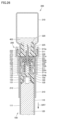
上述したシリンジ100とバイアル300との連結操作が完了した後には、図22に示す状態から、図中に示す矢印DR4方向に沿ってプランジャ120が押下される。これにより、図25に示すように、シリンジ100の内部に充填された第1薬剤401が、可動部材220に設けられた連通路225を経由してバイアル300へと導出される。これにより、バイアル300の内部において第1薬剤401と第2薬剤402とが混合されることになる。
そして、プランジャ120が完全に押下された後には、図中に示す矢印DR5方向に向けてバイアル300が振り動かされることで第1薬剤401と第2薬剤402との懸濁が行なわれる。
さらにその後、連結具200によって連結されたシリンジ100およびバイアル300が、図中に示す矢印DR6方向に向けて一体的にその天地が逆になるように反転されることにより、図26に示す状態とされる。
次に、図26に示す状態から、図中に示す矢印DR7方向に向けてプランジャ120が引き下げられる。これにより、図27に示すように、バイアル300の内部に収容された混合薬剤403(すなわち、第1薬剤401と第2薬剤402と懸濁された後の薬剤)が、可動部材220に設けられた連通路225を経由してシリンジ100へと導入される。
シリンジ100への混合薬剤403の導入が完了した後には、図27に示す状態から、図中に示す矢印DR8方向に向けてシリンジ100が、連結具200から引き抜かれる。このとき、使用者は、たとえばバレル110の筒状部111や指掛け部115を保持してその操作を行なうようにする。
この連結具200からのシリンジ100の引き抜きの際には、図28および図29に示すように、連結具本体210の前側筒部211に設けられた係止板211bが、上述したいわゆる返しとして機能するため、この係止板211bにキャップ150の第2立設部153に設けられた係止突起153bが当接することにより、キャップ150が連結具本体210に固定されることになり、キャップ150の後方に向けての移動が制限されることになる。すなわち、これら係止板211bと係止突起153bとが、キャップ150の連結具本体210の後端側に向けての移動を不能にする係止機構として機能することになる。
これにより、キャップ150の第2立設部153に設けられた係合突起153aとバレル110の囲繞部113に設けられた係合突起113aとの係合が解除されることになり、キャップ150がバレル110から取り外されることになる。
また、図28および図30に示すように、栓体140は、上述したように、キャップ150の第1立設部152に設けられた係止爪152aとキャップ150の基部151との間でその栓部141が挟み込まれて保持されているため、栓体140は、キャップ150と共にバレル110から取り外されることになる。
したがって、図28に示す状態からさらにシリンジ100が図中矢印DR8方向に引き抜かれることにより、栓体140およびキャップ150が取り外された状態で、混合薬剤403が充填されたシリンジ100のみが連結具200から取り外されることになる。
以上により、本実施の形態に係る薬剤投与具1を用いての薬剤混合操作が完了することになり、その後は、シリンジ100のノズル部112および囲繞部113に針基が取付けられ、患者への薬剤の投与(すなわち注射)が行なわれる。
上述したように、本実施の形態に係る薬剤投与具1においては、薬剤混合操作のうちのシリンジ100とバイアル300との連結操作において、シリンジ100に対する可動部材220の連動/非連動が所定のタイミングで切り替えられるように構成されているため、使用者が操作を誤った場合にも、連結具200の内部において第1薬剤401が漏れ出すことが確実に防止できることになる。
また、上述したように、本実施の形態に係る薬剤投与具1においては、連結具本体210によって可動部材220の移動ならびにシリンジ100の移動が案内される構成であるため、バイアル300の栓体320に対して前側針部222が斜めに挿し込まれたり、シリンジ100の栓体140に対して後側針部223が斜めに挿し込まれたりするといった不具合の発生を未然に防止することもできる。
さらには、上述したように、本実施の形態に係る薬剤投与具1においては、クリック感や外部からの視認により、シリンジ100とバイアル300との連結操作における所定の段階が完了したか否かを確認することが可能であるため、バイアル300の栓体320に対する前側針部222の刺通が不十分となったり、シリンジ100の栓体140に対する後側針部223の刺通が不十分となったりするといった不具合の発生も未然に防止することができる。
したがって、本実施の形態に係る薬剤投与具1とすることにより、各種の不具合の発生が防止された非常に使い勝手のよい薬剤投与具とすることができる。
加えて、本実施の形態に係る薬剤投与具1においては、シリンジ100の前端側の構成を簡素化することもできる。すなわち、上記特許文献1,2に開示の如くの薬剤投与具においては、連結具とシリンジとの接続およびその解除のために、ノズル部を取り囲むように設けられた囲繞部の内周面に雌ネジ部が設けられるのみならず、当該囲繞部の外周面に雄ネジ部が設けられている。しかしながら、本実施の形態に係る薬剤投与具1においては、囲繞部113の外周面にこのような雄ネジ部を設ける必要はない。したがって、本実施の形態に係る薬剤投与具1とすることにより、従来に比して構成が簡素化されることになるため、低コストに薬剤投与具を提供することも可能になる。
以上において説明した本実施の形態に係る薬剤投与具1の特徴的な構成を要約すれば、以下のとおりとなる。
[付記1]
第1薬剤が充填されたシリンジと、
上記第1薬剤を当該第1薬剤とは異なる第2薬剤に混合するために、上記シリンジを第2薬剤が封入されたバイアルに連結するための連結具とを備えた薬剤投与具であって、
上記シリンジは、
ノズル部、および、当該ノズル部を取り囲む囲繞部が前端に設けられたバレルと、
上記バレルに当該バレルの後端側から挿し込まれたプランジャと、
上記ノズル部を閉塞する栓体と、
上記栓体を保持するとともに上記囲繞部に着脱自在に取付けられたキャップとを有し、
上記連結具は、
バイアルの接続のための接続部が前端に設けられるとともに、上記シリンジが挿し込まれた筒状部が上記接続部よりも後端側の位置に設けられた連結具本体と、
バイアルに刺通される前側針部、および、上記栓体に刺通可能な後側針部を含み、上記筒状部の内部を移動することができるように、上記連結具本体に対して相対的に移動可能に組付けられた可動部材とを有し、
上記シリンジは、上記連結具本体の前端側に向けて移動可能に上記連結具に接続され、
上記シリンジの上記連結具本体の前端側に向けての移動に連動して上記可動部材が上記連結具本体の前端側に向けて移動する連動状態と、上記シリンジの上記連結具本体の前端側に向けての移動に連動せずに上記可動部材が停止する非連動状態とに切り替える連動/非連動切替機構をさらに備えた、薬剤投与具。
[付記2]
上記シリンジは、上記栓体が上記連結具本体の後端寄りの位置である第1位置から上記第1位置よりも上記連結具本体の前端寄りの位置である第2位置を経由して上記第2位置よりも上記連結具本体のさらに前端寄りの位置である第3位置に配置されることとなるように、上記連結具本体の前端側に向けて移動可能に上記連結具に接続され、
上記栓体が上記第1位置にある状態において、上記後側針部が上記栓体に対向して位置するように、上記可動部材が予め配置され、
上記栓体が上記第1位置から上記第2位置に移動する、上記シリンジの上記連結具本体の前端側に向けての移動の始めの段階において、上記連動/非連動切替機構によって上記連動状態が維持されることにより、上記後側針部が上記栓体に対向して位置した状態が維持されつつ、上記可動部材が上記連結具本体の前端側に向けて移動するとともに、上記栓体が上記第2位置から上記第3位置に移動する、上記シリンジの上記連結具本体の前端側に向けての移動の終わりの段階において、上記連動/非連動切替機構によって上記非連動状態に切り替えられることにより、上記可動部材が停止した状態が維持されつつ上記栓体が上記連結具本体の前端側に向けて移動することにより、上記後側針部が上記栓体に刺通されるように構成された、付記1に記載の薬剤投与具。
[付記3]
上記可動部材が、上記前側針部および上記後側針部を支持する基部と、上記基部の周縁から上記連結具本体の後端側に向けて立設されるとともに、外縁が上記連結具本体の後端側に位置しかつ内縁が上記連結具の前端側に位置する傾斜形状の第1当接面が設けられた立設部とを含み、
上記キャップが、上記第1当接面に対向して設けられ、外縁が上記連結具本体の後端側に位置しかつ内縁が上記連結具の前端側に位置する傾斜形状の第2当接面を含み、
上記筒状部が、上記接続部側に位置する前側筒部と、上記前側筒部よりも後端側に位置し、上記前側筒部の内形よりも小さい内形を有する後側筒部とを含み、
上記連動/非連動切替機構が、上記第1当接面、上記第2当接面、上記前側筒部および上記後側筒部にて構成され、
上記立設部が上記後側筒部の内側に位置することで上記立設部の外側に向けての変形が上記後側筒部によって規制されることにより、上記第2当接面が上記第1当接面に当接した状態が維持されることで上記連動状態が実現され、
上記立設部が上記後側筒部の内側を通過して上記前側筒部の内側に位置することで上記立設部の外側に向けての変形が許容されることにより、上記第2当接面が上記第1当接面に当接した状態が解除されることで上記非連動状態が実現される、付記2に記載の薬剤投与具。
[付記4]
上記栓体が上記第3位置に配置された状態において、上記キャップを上記連結具本体に固定することで上記キャップの上記連結具本体の後端側に向けての移動を不能にする係止機構をさらに備え、
上記係止機構によって上記キャップが上記連結具本体に固定されることにより、上記シリンジを上記連結具本体の後端側に向けて移動させることにより、上記キャップおよび上記栓体が取り除かれた状態として上記シリンジを上記連結具から取り外すことが可能である、付記2または3に記載の薬剤投与具。
上記栓体が上記第3位置に配置された状態において、上記キャップを上記連結具本体に固定することで上記キャップの上記連結具本体の後端側に向けての移動を不能にする係止機構をさらに備え、
上記係止機構によって上記キャップが上記連結具本体に固定されることにより、上記シリンジを上記連結具本体の後端側に向けて移動させることにより、上記キャップおよび上記栓体が取り除かれた状態として上記シリンジを上記連結具から取り外すことが可能である、付記2または3に記載の薬剤投与具。
[付記5]
上記栓体が上記第1位置に配置された状態において、上記キャップを上記連結具本体に軽保持させる第1保持機構をさらに備えた、付記2から4のいずれかに記載の薬剤投与具。
上記栓体が上記第1位置に配置された状態において、上記キャップを上記連結具本体に軽保持させる第1保持機構をさらに備えた、付記2から4のいずれかに記載の薬剤投与具。
[付記6]
上記栓体が上記第1位置に配置された状態において、上記可動部材を上記連結具本体に軽保持させる第2保持機構をさらに備えた、付記2から5のいずれかに記載の薬剤投与具。
上記栓体が上記第1位置に配置された状態において、上記可動部材を上記連結具本体に軽保持させる第2保持機構をさらに備えた、付記2から5のいずれかに記載の薬剤投与具。
なお、上述した本発明の実施の形態においては、連動/非連動切替機構として、可動部材に設けられた第1当接面、キャップに設けられた第2当接面、連結具本体に設けられた前側筒部および後側筒部によってこれが構成されてなる場合を例示して説明を行なったが、他の部位からなるものにてこれを構成することとしてもよく、連動/非連動切替機構は、上記の構成のものに限られない。
また、上述した本発明の実施の形態において説明した各部の数や形状、配置位置等は、本発明の趣旨を逸脱しない限りにおいて適宜その変更が可能である。これらの変更に伴い、薬液混合操作に含まれる各種の操作についても、これを適宜変更することが可能である。たとえば連結具にシリンジやバイアルを接続する際の操作を単なる挿し込みに代えて捩じ込みにしたり、連結具からシリンジを取り外す際の操作を単なる引き抜きに代えて回転を伴った引き抜きにしたりしてもよい。
このように、今回開示した上記実施の形態はすべての点で例示であって、制限的なものではない。本発明の技術的範囲は請求の範囲によって画定され、また請求の範囲の記載と均等の意味および範囲内でのすべての変更を含むものである。
1 薬剤投与具、100 シリンジ、110 バレル、111 筒状部、112 ノズル部、113 囲繞部、113a 係合突起、114 雌ネジ部、115 指掛け部、120 プランジャ、121 凸状部、122 雄ネジ部、130 パッキン、131 凹状部、132 雌ネジ部、140 栓体、141 栓部、142 宛がい部、150 キャップ、151 基部、151a 開口部、152 第1立設部、152a 係止爪、152b 第2当接面、153 第2立設部、153a 係合突起、153b 係止突起、200 連結具、210 連結具本体、211 前側筒部、211a 係合突起、211b 係止板、212 後側筒部、212a 係止板、212b 係止孔、213 接続部、213a 係合突起、220 可動部材、221 基部、222 前側針部、223 後側針部、224 立設部、224a 係合突起、224b 第1当接面、224c 係合孔、225 連通路、300 バイアル、310 容器本体、311 口部、320 栓体、330 封止部材、331 開口部、401 第1薬剤、402 第2薬剤、403 混合薬剤。
Claims (6)
- 第1薬剤が充填されたシリンジと、
前記第1薬剤を当該第1薬剤とは異なる第2薬剤に混合するために、前記シリンジを第2薬剤が封入されたバイアルに連結するための連結具とを備えた薬剤投与具であって、
前記シリンジは、
ノズル部、および、当該ノズル部を取り囲む囲繞部が前端に設けられたバレルと、
前記バレルに当該バレルの後端側から挿し込まれたプランジャと、
前記ノズル部を閉塞する栓体と、
前記栓体を保持するとともに前記囲繞部に着脱自在に取付けられたキャップとを有し、
前記連結具は、
バイアルの接続のための接続部が前端に設けられるとともに、前記シリンジが挿し込まれた筒状部が前記接続部よりも後端側の位置に設けられた連結具本体と、
バイアルに刺通される前側針部、および、前記栓体に刺通可能な後側針部を含み、前記筒状部の内部を移動することができるように、前記連結具本体に対して相対的に移動可能に組付けられた可動部材とを有し、
前記シリンジは、前記連結具本体の前端側に向けて移動可能に前記連結具に接続され、
前記シリンジの前記連結具本体の前端側に向けての移動に連動して前記可動部材が前記連結具本体の前端側に向けて移動する連動状態と、前記シリンジの前記連結具本体の前端側に向けての移動に連動せずに前記可動部材が停止する非連動状態とに切り替える連動/非連動切替機構をさらに備えた、薬剤投与具。 - 前記シリンジは、前記栓体が前記連結具本体の後端寄りの位置である第1位置から前記第1位置よりも前記連結具本体の前端寄りの位置である第2位置を経由して前記第2位置よりも前記連結具本体のさらに前端寄りの位置である第3位置に配置されることとなるように、前記連結具本体の前端側に向けて移動可能に前記連結具に接続され、
前記栓体が前記第1位置にある状態において、前記後側針部が前記栓体に対向して位置するように、前記可動部材が予め配置され、
前記栓体が前記第1位置から前記第2位置に移動する、前記シリンジの前記連結具本体の前端側に向けての移動の始めの段階において、前記連動/非連動切替機構によって前記連動状態が維持されることにより、前記後側針部が前記栓体に対向して位置した状態が維持されつつ、前記可動部材が前記連結具本体の前端側に向けて移動するとともに、前記栓体が前記第2位置から前記第3位置に移動する、前記シリンジの前記連結具本体の前端側に向けての移動の終わりの段階において、前記連動/非連動切替機構によって前記非連動状態に切り替えられることにより、前記可動部材が停止した状態が維持されつつ前記栓体が前記連結具本体の前端側に向けて移動することにより、前記後側針部が前記栓体に刺通されるように構成された、請求項1に記載の薬剤投与具。 - 前記可動部材が、前記前側針部および前記後側針部を支持する基部と、前記基部の周縁から前記連結具本体の後端側に向けて立設されるとともに、外縁が前記連結具本体の後端側に位置しかつ内縁が前記連結具の前端側に位置する傾斜形状の第1当接面が設けられた立設部とを含み、
前記キャップが、前記第1当接面に対向して設けられ、外縁が前記連結具本体の後端側に位置しかつ内縁が前記連結具の前端側に位置する傾斜形状の第2当接面を含み、
前記筒状部が、前記接続部側に位置する前側筒部と、前記前側筒部よりも後端側に位置し、前記前側筒部の内形よりも小さい内形を有する後側筒部とを含み、
前記連動/非連動切替機構が、前記第1当接面、前記第2当接面、前記前側筒部および前記後側筒部にて構成され、
前記立設部が前記後側筒部の内側に位置することで前記立設部の外側に向けての変形が前記後側筒部によって規制されることにより、前記第2当接面が前記第1当接面に当接した状態が維持されることで前記連動状態が実現され、
前記立設部が前記後側筒部の内側を通過して前記前側筒部の内側に位置することで前記立設部の外側に向けての変形が許容されることにより、前記第2当接面が前記第1当接面に当接した状態が解除されることで前記非連動状態が実現される、請求項2に記載の薬剤投与具。 - 前記栓体が前記第3位置に配置された状態において、前記キャップを前記連結具本体に固定することで前記キャップの前記連結具本体の後端側に向けての移動を不能にする係止機構をさらに備え、
前記係止機構によって前記キャップが前記連結具本体に固定されることにより、前記シリンジを前記連結具本体の後端側に向けて移動させることにより、前記キャップおよび前記栓体が取り除かれた状態として前記シリンジを前記連結具から取り外すことが可能である、請求項2に記載の薬剤投与具。 - 前記栓体が前記第1位置に配置された状態において、前記キャップを前記連結具本体に軽保持させる第1保持機構をさらに備えた、請求項2に記載の薬剤投与具。
- 前記栓体が前記第1位置に配置された状態において、前記可動部材を前記連結具本体に軽保持させる第2保持機構をさらに備えた、請求項2に記載の薬剤投与具。
Applications Claiming Priority (2)
| Application Number | Priority Date | Filing Date | Title |
|---|---|---|---|
| JP2022146407 | 2022-09-14 | ||
| JP2022-146407 | 2022-09-14 |
Publications (1)
| Publication Number | Publication Date |
|---|---|
| WO2024057691A1 true WO2024057691A1 (ja) | 2024-03-21 |
Family
ID=90274600
Family Applications (1)
| Application Number | Title | Priority Date | Filing Date |
|---|---|---|---|
| PCT/JP2023/025553 WO2024057691A1 (ja) | 2022-09-14 | 2023-07-11 | 薬剤投与具 |
Country Status (1)
| Country | Link |
|---|---|
| WO (1) | WO2024057691A1 (ja) |
Citations (3)
| Publication number | Priority date | Publication date | Assignee | Title |
|---|---|---|---|---|
| JP2011194045A (ja) * | 2010-03-19 | 2011-10-06 | Terumo Corp | 薬剤投与具 |
| JP2015509431A (ja) * | 2012-03-05 | 2015-03-30 | ベクトン・ディキンソン・アンド・カンパニーBecton, Dickinson And Company | 薬剤の再構成のためのフローティングニードルを備えた移送セット |
| WO2020196848A1 (ja) * | 2019-03-28 | 2020-10-01 | 株式会社モリモト医薬 | シリンジ用の調製補助具 |
-
2023
- 2023-07-11 WO PCT/JP2023/025553 patent/WO2024057691A1/ja unknown
Patent Citations (3)
| Publication number | Priority date | Publication date | Assignee | Title |
|---|---|---|---|---|
| JP2011194045A (ja) * | 2010-03-19 | 2011-10-06 | Terumo Corp | 薬剤投与具 |
| JP2015509431A (ja) * | 2012-03-05 | 2015-03-30 | ベクトン・ディキンソン・アンド・カンパニーBecton, Dickinson And Company | 薬剤の再構成のためのフローティングニードルを備えた移送セット |
| WO2020196848A1 (ja) * | 2019-03-28 | 2020-10-01 | 株式会社モリモト医薬 | シリンジ用の調製補助具 |
Similar Documents
| Publication | Publication Date | Title |
|---|---|---|
| JP5888606B2 (ja) | 薬剤調製器具 | |
| US11065388B2 (en) | Medicament packaging | |
| EP2453958B1 (en) | Apparatus for selectively establishing a needleless injection port on iv tubing, and associated methods | |
| KR20050057664A (ko) | 미리 충전되고 밀봉된 약물 백, 포트 및 백과 투여 세트사이에 유체 연결을 형성하기 위한 방법 | |
| JPH10510740A (ja) | 無針注射器カートリッジのための充填装置 | |
| JP2017221440A (ja) | 空気吸引用キャップ | |
| WO2018209668A1 (zh) | 密闭系统配药给药装置 | |
| JPH11114065A (ja) | 点鼻薬用の噴霧アダプタと、それを使用する点鼻薬用の噴霧セット | |
| JP5984059B2 (ja) | 薬液混注器具 | |
| WO2024057691A1 (ja) | 薬剤投与具 | |
| JPH1189934A (ja) | プレフィルドシリンジ | |
| WO2009096227A1 (ja) | 穿刺針組立体および薬液注入器具 | |
| GB2556088A (en) | Packaging and devices for mixing medicament substances | |
| JP5411729B2 (ja) | 薬剤投与具 | |
| JP3419145B2 (ja) | プレフィルドシリンジ | |
| US20130303995A1 (en) | Medical instrument with attached needle | |
| WO2017170635A1 (ja) | 薬液投与器具、薬液投与器具の使用方法及び薬液投与器具の製造方法 | |
| CN113631134A (zh) | 注射器用混合辅助工具 | |
| WO2021182370A1 (ja) | シリンジセット及びシリンジ並びにセット | |
| WO2013089105A1 (ja) | プレフィルドシリンジ用筒状体、プレフィルドシリンジ用穿刺具、プレフィルドシリンジ用注射器およびプレフィルドシリンジ | |
| JPH08150208A (ja) | 注射器 | |
| TWI637761B (zh) | Closed system dispensing device | |
| CN110475574B (zh) | 药液投放器具及垫圈弹压部件组装体 | |
| WO2022191261A1 (ja) | 連結器具及び薬剤調製用デバイス | |
| JP2023183914A (ja) | アダプタ及びアダプタ付きシリンジ |
Legal Events
| Date | Code | Title | Description |
|---|---|---|---|
| 121 | Ep: the epo has been informed by wipo that ep was designated in this application |
Ref document number: 23865053 Country of ref document: EP Kind code of ref document: A1 |