WO2024057679A1 - 振動発生装置および触覚生成装置 - Google Patents
振動発生装置および触覚生成装置 Download PDFInfo
- Publication number
- WO2024057679A1 WO2024057679A1 PCT/JP2023/024763 JP2023024763W WO2024057679A1 WO 2024057679 A1 WO2024057679 A1 WO 2024057679A1 JP 2023024763 W JP2023024763 W JP 2023024763W WO 2024057679 A1 WO2024057679 A1 WO 2024057679A1
- Authority
- WO
- WIPO (PCT)
- Prior art keywords
- piezoelectric
- piezoelectric element
- electrode
- wave
- frequency
- Prior art date
- Legal status (The legal status is an assumption and is not a legal conclusion. Google has not performed a legal analysis and makes no representation as to the accuracy of the status listed.)
- Ceased
Links
Images










Classifications
-
- B—PERFORMING OPERATIONS; TRANSPORTING
- B06—GENERATING OR TRANSMITTING MECHANICAL VIBRATIONS IN GENERAL
- B06B—METHODS OR APPARATUS FOR GENERATING OR TRANSMITTING MECHANICAL VIBRATIONS OF INFRASONIC, SONIC, OR ULTRASONIC FREQUENCY, e.g. FOR PERFORMING MECHANICAL WORK IN GENERAL
- B06B1/00—Methods or apparatus for generating mechanical vibrations of infrasonic, sonic, or ultrasonic frequency
- B06B1/02—Methods or apparatus for generating mechanical vibrations of infrasonic, sonic, or ultrasonic frequency making use of electrical energy
- B06B1/04—Methods or apparatus for generating mechanical vibrations of infrasonic, sonic, or ultrasonic frequency making use of electrical energy operating with electromagnetism
-
- B—PERFORMING OPERATIONS; TRANSPORTING
- B06—GENERATING OR TRANSMITTING MECHANICAL VIBRATIONS IN GENERAL
- B06B—METHODS OR APPARATUS FOR GENERATING OR TRANSMITTING MECHANICAL VIBRATIONS OF INFRASONIC, SONIC, OR ULTRASONIC FREQUENCY, e.g. FOR PERFORMING MECHANICAL WORK IN GENERAL
- B06B1/00—Methods or apparatus for generating mechanical vibrations of infrasonic, sonic, or ultrasonic frequency
- B06B1/02—Methods or apparatus for generating mechanical vibrations of infrasonic, sonic, or ultrasonic frequency making use of electrical energy
- B06B1/06—Methods or apparatus for generating mechanical vibrations of infrasonic, sonic, or ultrasonic frequency making use of electrical energy operating with piezoelectric effect or with electrostriction
-
- H—ELECTRICITY
- H04—ELECTRIC COMMUNICATION TECHNIQUE
- H04R—LOUDSPEAKERS, MICROPHONES, GRAMOPHONE PICK-UPS OR LIKE ACOUSTIC ELECTROMECHANICAL TRANSDUCERS; ELECTRIC HEARING AIDS; PUBLIC ADDRESS SYSTEMS
- H04R17/00—Piezoelectric transducers; Electrostrictive transducers
-
- H—ELECTRICITY
- H04—ELECTRIC COMMUNICATION TECHNIQUE
- H04R—LOUDSPEAKERS, MICROPHONES, GRAMOPHONE PICK-UPS OR LIKE ACOUSTIC ELECTROMECHANICAL TRANSDUCERS; ELECTRIC HEARING AIDS; PUBLIC ADDRESS SYSTEMS
- H04R17/00—Piezoelectric transducers; Electrostrictive transducers
- H04R17/10—Resonant transducers, i.e. adapted to produce maximum output at a predetermined frequency
Definitions
- the present invention relates to a vibration generating device and a tactile sensation generating device.
- piezoelectric elements in vibration generators, such as transducers that convert electrical signals into sound waves. It is known to use a Langevin type vibrator having a diaphragm to generate ultrasonic waves.
- the output will decrease if the diaphragm is made smaller.
- a structure without a diaphragm allows for miniaturization, but it is difficult to achieve high output. As described above, it has been difficult to achieve both miniaturization and high output of the vibration generator.
- a tactile sensation generation device is required to express a soft tactile sensation on a hard material.
- the present invention was made in view of the above problems, and aims to reduce the size and increase the output, or to express a soft tactile sensation.
- the present invention includes a piezoelectric layer, and a first electrode and a second electrode sandwiching the piezoelectric layer, and by applying a voltage between the first electrode and the second electrode, the first electrode and a piezoelectric element in which the second electrode expands and contracts in a direction sandwiching the piezoelectric layer, and a first member and a second member sandwiching the piezoelectric element in the direction, the first member and the second member being the
- the vibration generator includes a casing that presses a piezoelectric element in the direction, and the first member outputs a sound wave corresponding to expansion and contraction of the piezoelectric element in the direction.
- the first member and the second member are configured to press the piezoelectric element by fitting together a thread provided on the first member and a thread provided on the second member. It can be done.
- a third member is provided to which the first member and the second member are joined, and a thread provided on the first member and a thread provided on the third member are fitted, and The first member and the second member are configured to press the piezoelectric element by fitting together a thread provided on the second member and a thread provided on the third member. Can be done.
- a fourth member is provided between the first member and the piezoelectric element and has a Young's modulus larger than the Young's modulus of the first member and the Young's modulus of the piezoelectric layer;
- the fifth member may be provided between the piezoelectric element and have a Young's modulus larger than the Young's modulus of the second member and the Young's modulus of the piezoelectric layer.
- the pressure with which the first member and the second member press the piezoelectric element may be 5 ⁇ 10 5 Pa or more.
- a plurality of the piezoelectric layers, a plurality of the first electrodes, and a plurality of the second electrodes are provided, the plurality of first electrodes and the second electrodes are provided alternately in the direction, and the plurality of piezoelectric layers
- One of the electrodes may be sandwiched in the direction between one of the plurality of first electrodes and one of the plurality of second electrodes.
- the first member outputs the sound wave to the space in the direction, and applies a frequency of 0.86 times or more and 1.14 times or less of the resonant frequency of the casing to the piezoelectric element as the voltage.
- the modulated wave may be supplied by amplitude modulating a carrier wave with a signal wave having a frequency lower than the frequency of the carrier wave.
- the frequency of the signal wave may be 70 Hz or more and 1000 Hz or less.
- the first member outputs the sound wave to the space in the direction, and applies the voltage to the piezoelectric element at a frequency of 0.86 or more and 1.14 times or less of the resonant frequency of the casing.
- a first carrier wave having a frequency of 50 Hz or more and 300 Hz or less is amplitude-modulated with a first modulated wave having a frequency of 1 Hz or more and 60 Hz or less; It can be configured to supply a modulated wave.
- the surface of the first member on the space side may have a center portion recessed toward the piezoelectric element.
- the piezoelectric element may be provided with a drive device that supplies the modulated wave as the voltage.
- the voltage is supplied to the piezoelectric element so that when the surface of the first member in the direction is pressed against the pressed member, a sound wave is generated from the pressed member. Can be done.
- a pressing member that presses the surface of the first member against the pressed member, and a drive device that supplies the voltage to the piezoelectric element;
- the configuration may include the following.
- the present invention provides a vibrator and a carrier wave having a frequency of 0.86 times or more and 1.14 times or less of the resonant frequency of the vibrator, and a rectangular wave having a frequency of 1 Hz or more and 60 Hz or less lower than the frequency of the carrier wave.
- a tactile sensation generating device includes: a drive device that generates a modulated wave whose amplitude is modulated by a signal wave having a degree of modulation of 50% or more and less than 100%, and supplies the modulated wave to the vibrator.
- the vibrator includes a piezoelectric layer, and a first electrode and a second electrode sandwiching the piezoelectric layer, and applies a voltage between the first electrode and the second electrode.
- the first electrode and the second electrode include a piezoelectric element that expands and contracts in a direction sandwiching the piezoelectric layer, and a first member and a second member that sandwich the piezoelectric element in the direction, and the first member and the second electrode
- the two members may include a casing that presses the piezoelectric element in the direction and outputs vibrations corresponding to expansion and contraction of the piezoelectric element.
- the first member and the second member may be configured to press the piezoelectric element by fitting screws together.
- a third member is provided between the first member and the piezoelectric element and has a Young's modulus larger than the Young's modulus of the first member and the Young's modulus of the piezoelectric layer;
- the fourth member may be provided between the piezoelectric element and have a Young's modulus larger than the Young's modulus of the second member and the Young's modulus of the piezoelectric layer.
- the pressure with which the first member and the second member press the piezoelectric element may be 5 ⁇ 10 5 Pa or more.
- a plurality of the piezoelectric layers, a plurality of the first electrodes, and a plurality of the second electrodes are provided, the plurality of first electrodes and the second electrodes are provided alternately in the direction, and the plurality of piezoelectric layers
- One of the electrodes may be sandwiched in the direction between one of the plurality of first electrodes and one of the plurality of second electrodes.
- the structure may include a member that contacts at least a portion of the housing, transmits vibrations from the at least one portion, and is softer than the at least one portion.
- the modulation degree may be 98% or less.
- the frequency of the signal wave is 3 Hz or more and 50 Hz or less.
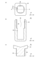
- FIG. 1(a) is a plan view of the vibration generating element according to Example 1
- FIG. 1(b) is a sectional view taken along line AA in FIG. 1(a).
- 2(a) is a plan view of the second member in Example 1
- FIG. 2(b) is a sectional view taken along line AA in FIG. 2(a)
- FIG. 2(c) is a sectional view of the first member.
- FIG. 3 is a cross-sectional view of the piezoelectric element in Example 1.
- FIG. 4 is a schematic diagram of the vibration generator according to the second embodiment.
- FIG. 5 is a diagram showing a modulated wave that the drive device supplies to the piezoelectric element in Example 2.
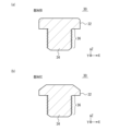
- FIG. 6(a) and 6(b) are cross-sectional views of the second member in Experiment 1.
- FIG. 7 is a diagram showing a modulated wave that the drive device supplies to the piezoelectric element in the first modification of the second embodiment.
- FIG. 8 is a schematic diagram of a vibration generator according to a second modification of the second embodiment.
- FIG. 9 is a schematic diagram of a vibration generator according to Example 3.
- FIG. 10(a) is a plan view of the pressing member in Example 3
- FIG. 10(b) is a sectional view taken along line AA in FIG. 10(a).
- FIG. 11 is a cross-sectional view of a vibration generating element according to Example 4.
- FIG. 12 is a schematic diagram of a vibration generator according to Modification 1 of Example 4.
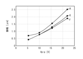
- FIG. 13 shows Experiment 2.
- FIG. 3 is a diagram showing amplitude versus Vp-p.
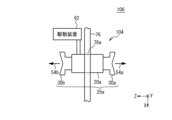
- FIG. 14 is a schematic diagram of a vibration generator according to a third modification of the fourth embodiment.
- FIG. 15 is a schematic diagram of a tactile sensation generation device according to Example 5.
- FIG. 16(a) is a plan view of the vibrator in Example 5
- FIG. 16(b) is a sectional view taken along line AA in FIG. 16(a).
- 17(a) is a plan view of the second member of the vibrator in Example 6
- FIG. 17(b) is a sectional view taken along line AA in FIG. 17(a)
- FIG. 17(c) is a plan view of the second member of the vibrator in Example 6.
- FIG. 18 is a cross-sectional view of a piezoelectric element in Example 5.
- FIG. 19 is a diagram showing a modulated wave that the drive device supplies to the piezoelectric element in Example 5.
- 20(a) and 20(b) are cross-sectional views showing another example of the second member in Example 5.
- FIG. FIG. 21 is a schematic diagram of a tactile sensation generating device according to Modification 1 of Example 5.
- 22(a) is a sectional view of the first member of the vibrator in Example 6, and
- FIG. 22(b) is a sectional view of the second member of the vibrator in Example 6.
- FIG. 23 is a schematic diagram of a tactile sensation generating device in Example 7.
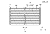
- FIG. 24(a) is a plan view of the tactile sensation generating device in Example 8, and
- FIG. 24(b) is a sectional view taken along line AA in FIG. 24(a).
- FIG. 25 is a cross-sectional view of a vibrator in the eighth embodiment.
- Example 1 a vibration generator that can improve the Q value of mechanical vibration of a housing will be described.
- FIG. 1(a) is a plan view of the vibration generating element according to Example 1
- FIG. 1(b) is a sectional view taken along line AA in FIG. 1(a).
- 2(a) is a plan view of the second member in Example 1
- FIG. 2(b) is a sectional view taken along line AA in FIG. 2(a)
- FIG. 2(c) is a sectional view of the first member. It is.
- the housing 25 includes a first member 30 and a second member 20.
- the first member 30 and the second member 20 are joined.
- a recess 28 is provided on the surface of the second member 20 in the +Z direction.
- the recess 28 has a first portion 22 provided on the +Z side and a second portion 24 provided on the ⁇ Z side.
- the first portion 22 has a substantially circular planar shape
- the second portion 24 has a substantially rectangular planar shape.
- a thread 26 serving as a female thread is formed on the side surface of the first portion 22 . No threads are formed on the side surface of the second portion 24.
- the support member 12a, the piezoelectric elements 10a and 10b, and the support member 12b are inserted into the recess 28 in this order from the ⁇ Z side.
- the support member 12a, the piezoelectric elements 10a and 10b, and the support member 12b are not joined to the second member 20 and are free to move.
- the first member 30 includes a head 32 provided on the +Z side and a threaded portion 34 provided on the -Z side.
- the planar shape of the head 32 is approximately circular.
- the +Z side surface of the head 32 has a central portion recessed in an inverted conical shape in the ⁇ Z direction relative to the peripheral portion in plan view.
- a thread 36 serving as a male thread is formed on the side surface of the threaded portion 34 .
- the threaded portion 34 of the first member 30 is joined to the first portion 22 of the recess 28 of the second member 20 by fitting the threads 26 and 36 together. By tightening the screw, the second member 20 presses the piezoelectric element 10a in the +Z direction as indicated by the arrow 50a via the support member 12a.
- the first member 30 presses the piezoelectric element 10b in the -Z direction as indicated by an arrow 50b via the support member 12b.
- the stress that presses the piezoelectric elements 10a and 10b is, for example, 5 ⁇ 10 6 Pa or more.
- the material of the first member 30 and the second member 20 is, for example, metal or resin.
- the material of the supporting members 12a and 12b has a larger Young's modulus than the first member 30, the second member 20, and the piezoelectric elements 10a and 10b, and is, for example, stainless steel or aluminum.
- the width of the head 32 of the first member 30 in the X direction and the Y direction is, for example, 10 mm, and the height of the head 32 in the Z direction is, for example, 2.5 mm.
- the amount of recess is, for example, 1.5 mm
- the width of the threaded portion 34 in the X direction and the Y direction is, for example, 6 mm
- the height of the threaded portion 34 in the Z direction is, for example, 5 mm.
- the width of the second member 20 in the X direction and the Y direction is, for example, 8 mm
- the height is, for example, 15 mm
- the depth of the recess 28 in the Z direction is, for example, 14 mm
- the depth of the first portion 22 in the Z direction is, for example,
- the width of the second portion 24 in the X direction and the Y direction is, for example, 4.5 mm.
- the materials, shapes, and dimensions of the first member 30, the second member 20, and the support members 12a and 12b can be designed as appropriate.
- FIG. 3 is a cross-sectional view of the piezoelectric element in Example 1.
- the piezoelectric elements 10a and 10b include a piezoelectric body 40 made up of a plurality of piezoelectric layers 41, a plurality of first electrodes 42, and a plurality of second electrodes 44.
- the plurality of piezoelectric layers 41 are stacked in the Z direction.
- the piezoelectric layer 41, the first electrode 42, and the second electrode 44 have a flat plate shape extending in the XY plane.
- the plurality of first electrodes 42 and the plurality of second electrodes 44 are provided alternately in the Z direction.
- One piezoelectric layer 41 is sandwiched between one first electrode 42 and one second electrode 44 in the Z direction.
- a first external electrode 43 is provided on the side surface of the piezoelectric body 40 on the ⁇ X side, and a second external electrode 45 is provided on the side surface of the piezoelectric body 40 on the +X side.
- the plurality of first electrodes 42 are electrically connected to the first external electrode 43.
- the plurality of second electrodes 44 are electrically connected to the second external electrode 45 .
- the piezoelectric body 40 includes a first region 46, a second region 47, and a third region 48.
- the first regions 46 and the second regions 47 are provided alternately in the Z direction.
- the third region 48 is provided outside the outermost first region 46 in the Z direction.
- the first region 46 is a region in which first electrodes 42 and second electrodes 44 are alternately provided at regular intervals in the Z direction.
- the number of stacked piezoelectric layers 41 in the first region 46 is, for example, 50 layers.
- the second region 47 and the third region 48 are regions where the first electrode 42 and the second electrode 44 are not provided.
- the second region 47 may not be provided. Providing the second region 47 may improve reliability in some cases.
- Examples of the material of the piezoelectric layer 41 include lead zirconate titanate (PZT:Pb(Zr,Ti)O 3 ), barium titanate material (BaTiO 3 , Ba may be Ca, Ti may be Zr), A bismuth titanate material (BiTiO 3 , in which part of Bi may be Na) or an alkali niobate material (NaNbO 3 , in which Na may be Li or K) can be used.
- metals such as Ag, Pd, Pt, Cu, Ni, and Au can be used, for example.
- the piezoelectric elements 10a and 10b are chips made of sintered bodies formed by laminating and sintering piezoelectric sheets each having a first electrode 42 and a second electrode 44 formed on their surfaces.
- the piezoelectric elements 10a and 10b are, for example, rectangular parallelepipeds, and the widths of the piezoelectric elements 10a and 10b in the X and Y directions are, for example, 3.5 mm, and the heights in the Z direction are, for example, 3 mm.
- d33 is a constant related to the piezoelectric constant
- the piezoelectric elements 10a and 10b can be stacked in the Z direction within the housing 25. Thereby, the total amount of displacement of piezoelectric elements 10a and 10b can be increased.
- the number of piezoelectric elements 10a and 10b stacked in the Z direction may be one or three or more.
- the Q value is improved compared to the case where the housing 25 does not press the piezoelectric elements 10a and 10b.
- Such a phenomenon cannot be obtained when transverse displacement mode piezoelectric elements are used as the piezoelectric elements 10a and 10b, and is a phenomenon discovered for the first time by the inventors.
- the lateral displacement mode is a mode in which the vibration direction of the piezoelectric elements 10a and 10b is orthogonal to the lamination direction of the first electrode 42 and the second electrode 44.
- the resonance frequency does not change much depending on whether or not the piezoelectric elements 10a and 10b are pressed. This is thought to be due to the provision of the support member 12a.
- the first electrode 42 and the second electrode 44 sandwich the piezoelectric layer 41 in the Z direction, and a voltage is applied between the first electrode 42 and the second electrode 44.
- piezoelectric elements 10a and 10b that expand and contract in the Z direction are used.
- the first member 30 and the second member 20 press the piezoelectric element 10a in the Z direction, and the first member 30 emits sound waves corresponding to the expansion and contraction of the piezoelectric elements 10a and 10b in the Z direction. Output.
- the housing 25 presses the vertical displacement piezoelectric elements 10a and 10b, thereby improving the Q value of the mechanical vibration of the housing 25. Therefore, high output is possible even in a small vibration generator that does not have a diaphragm.
- the first member 30 and the second member 20 press the piezoelectric elements 10a and 10b by fitting the screw threads 26 and 36 together. Thereby, the piezoelectric elements 10a and 10b can be stably pressed with a large force. Furthermore, variations in the pressure applied to the piezoelectric elements 10a and 10b can be suppressed. Therefore, variations in resonance frequency, etc. can be suppressed. As an example, when a plurality of structures were manufactured, the variation in resonance frequency was 600 Hz or less.
- the mechanism for pressing the piezoelectric elements 10a and 10b may be other than screw fitting.
- Example 1 when the nominal diameter d (maximum diameter) of the thread 36 of the first member 30 was 6 mm, the tightening torque T of the first member 30 was measured using a torque wrench and was approximately 0.1 N ⁇ m. .
- the area of the piezoelectric elements 10a and 10b in the XY plane is 3.5 mm x 3.5 mm. Therefore, the pressure with which the first member 30 presses the piezoelectric element 10b is 6.8 ⁇ 10 6 Pa.
- the pressure with which the first member 30 and the second member 20 press the piezoelectric elements 10a and 10b is preferably 5 ⁇ 10 5 Pa or more, more preferably 1 ⁇ 10 6 Pa or more, and even more preferably 2 ⁇ 10 6 Pa or more. preferable.
- the pressure with which the first member 30 and the second member 20 press against the piezoelectric elements 10a and 10b is set to be less than or equal to the pressure at which the piezoelectric elements 10a and 10b are destroyed.
- a support member 12b (fourth member) is provided between the first member 30 and the piezoelectric element 10b, and a support member 12a (fifth member) is provided between the second member 20 and the piezoelectric element 10a. At least one of support members 12a and 12b may be provided.
- the Young's modulus of PZT is approximately 60 GPa.
- resin is used as the housing 25, the Young's modulus of the resin is 10 GPa or less.
- the Young's modulus of stainless steel is about 120 GPa.
- the Young's modulus of aluminum is approximately 70 GPa.
- the Young's modulus of the supporting member 12b is greater than the Young's modulus of the piezoelectric body 40 and the Young's modulus of the first member 30, and the Young's modulus of the supporting member 12b is greater than the Young's modulus of the piezoelectric body 40 and the Young's modulus of the second member 20. greater than the rate.
- the Young's modulus of the supporting members 12b and 12a is preferably 1.2 times or more, more preferably 1.5 times or more, the Young's modulus of the piezoelectric body 40 and the Young's modulus of the first member 30 and the second member 20, respectively.
- the plurality of first electrodes 42 and the plurality of second electrodes 44 are provided alternately in the Z direction, and one of the plurality of piezoelectric layers 41 is It is sandwiched between one of the electrodes 42 and one of the plurality of second electrodes 44 in the Z direction.
- the amount of displacement in the Z direction can be increased, and the characteristics of the vibration generator can be further improved.
- Example 2 is an example in which the vibration generating element 100 of Example 1 is used in a vibration generator for spatial tactile sensation.
- FIG. 4 is a schematic diagram of the vibration generator according to the second embodiment.
- the housing 25 of the vibration generating element 100 of the first embodiment is fixed on the pedestal 60.
- the pedestal 60 has rigidity like a metal plate.
- the drive device 62 supplies a voltage between the first external electrode 43 and the second external electrode 45 of the piezoelectric elements 10a and 10b inside the housing 25.
- Sound waves 54 are emitted from the first member 30 in the Z direction.
- a part of the human body for example, a finger or a palm
- a tactile sensation is obtained by the sound waves 54.
- FIG. 5 is a diagram showing a modulated wave that the drive device supplies to the piezoelectric element in Example 2.
- the horizontal axis in FIG. 5 shows time, and the vertical axis shows voltage.
- the signal with period T1 (frequency f1) is a carrier wave 64.
- An envelope 65 of the modulated wave 66 corresponds to a signal wave.
- the signal wave has a period T2 (frequency f2).
- a sine wave is used as the carrier wave 64
- a triangular wave is shown as the carrier wave 64 for simplicity of illustration.
- the period T1 is much smaller than the period T2, the period T1 is illustrated in a larger size in FIG. 5 for ease of understanding.
- the carrier wave 64 is amplitude-modulated by a signal wave.
- both the carrier wave 64 and the signal wave are sine waves.
- the signal wave may be a rectangular wave, a triangular wave, a sawtooth wave, etc. other than a sine wave.
- the frequency f1 of the carrier wave 64 is, for example, the resonance frequency of the housing 25.
- the resonant frequency may be a fundamental wave or a harmonic.
- the frequency f2 of the signal wave is a frequency to which Pacinian corpuscles, which are receptors in the human skin, are sensitive. Such a frequency is, for example, 70 Hz or more and 1000 Hz or less.
- the frequency to which Pacinian corpuscles and the like are sensitive is 250 Hz.
- the modulation degree M of the modulated wave 66 is, for example, 50% or more and 100% or less, and 80% or more and 100% or less.
- FIG. 2(c) The second member in FIG. 2(c) was designated as member A.
- 6(a) and 6(b) are cross-sectional views of the second member in Experiment 1. As shown in FIG. 6(a), in member B, the +Z side surface of the head 32 is flat. As shown in FIG. 6(b), in the member C, the peripheral edge of the +Z side surface of the head 32 is inclined in the ⁇ Z direction.
- the materials of the first member 30, the second member 20, the supporting members 12a and 12b, and the configurations of the piezoelectric elements 10a and 10b were the same as in Experiment 1.
- the width of the head 32 of the first member 30 in the X and Y directions is 10 mm
- the height of the head 32 in the Z direction is 2.5 mm
- the amount of concavity at the apex of the inverted cone on the +Z surface of the head 32 is 1.
- the width of the threaded portion 34 in the X and Y directions is 6mm
- the height of the threaded portion 34 in the Z direction is 5mm.
- the width of the second member 20 in the X direction and the Y direction is 8 mm, the height is 15 mm, the depth of the recess 28 in the Z direction is 14 mm, the depth of the first part 22 in the Z direction is 6 mm, and the depth of the second part 24 is 15 mm.
- the width in the direction and Y direction is 4.5 mm.
- Table 1 is a table showing the experimental conditions and results of Samples A to C in Experiment 1.
- samples A to C are samples in which members A to C are used as the first member 30.
- Vp-p corresponds to the amplitude A1 in FIG.
- Carrier wave is the frequency of the carrier wave 64, which is the resonant frequency (second harmonic) of the housing 25.
- Signal wave is the frequency of the signal wave.
- the modulation degree M is 100% in all samples.
- D1 in FIG. 4 is the distance D1 in the +Z direction from the first member 30 at which the sound pressure level is 85 dB.
- “Tactile sensation” is the result of examining whether a tactile sensation can be obtained when a hand is placed over the first member 30 in the +Z direction. "1” indicates that a tactile sensation was obtained, “2” indicates that a tactile sensation was obtained to some extent, and “3” indicates that a tactile sensation was not obtained much.
- Vp-p is almost the same and the frequency of the carrier wave is almost the same.
- the frequency of the signal wave is the frequency to which Pacinian corpuscles are most sensitive.
- sample A had the largest distance D1 and provided the most tactile sensation.
- Samples B and C have approximately the same distance D1, but sample C has a greater tactile sensation. As described above, it was found that sample A provided the most tactile sensation. It was also found that an aerial tactile sensation was obtained in all of Samples A to C.
- Table 2 is a table showing experimental conditions and results using commercially available piezoelectric elements.
- Samples D and E use a commercially available transverse displacement mode piezoelectric element and a disc-shaped vibrating plate, and the piezoelectric element is provided with a member that emits sound waves like member A.
- the planar shape of the piezoelectric elements in Samples D and E is circular, and the diameters are 10 mm and 15 mm, respectively. Thus, samples D and E have large piezoelectric elements.
- “D1" is the distance D1 when the sound pressure level is 80 dB.
- the sound pressure levels to be determined for samples D and E are lower than those in Table 1, so a strict comparison cannot be made; however, the distance D1 between samples D and E is comparable to that of sample A.
- the planar area of the piezoelectric elements of Samples D and E is five times or more that of Sample A. In this way, sample A can obtain the same level of aerial tactile sensation as samples D and E, using piezoelectric elements 10a and 10b smaller than samples D and E, without using a diaphragm. In this way, sample A can be made smaller and have higher output.
- the vibration generator of the first embodiment is used, and the first member 30 has a structure in which the first member 30 outputs sound waves to the space in the Z direction.
- the piezoelectric elements 10a and 10b are supplied with a modulated wave 66 in which a carrier wave 64 having a frequency equal to the resonant frequency of the housing 25 is amplitude-modulated by a signal wave having a frequency lower than the frequency of the carrier wave 64 as a voltage. be done.
- high-output sound waves can be outputted into the space using the vibration generating element 100, which can be miniaturized since no diaphragm is used, so that the aerial tactile sensation can be increased.
- the frequency of the carrier wave 64 is set to a range of 0.86 times or more and 1.14 times or less of the resonance frequency, an aerial tactile sensation can be obtained.
- the frequency of the carrier wave 64 is more preferably 0.9 times or more and 1.1 times or less of the resonance frequency.
- the resonant frequency may be the resonant frequency of the fundamental mode or the resonant frequency of the harmonic mode.
- the frequency of the carrier wave 64 is, for example, 20 kHz or more and 110 kHz or less, and 30 kHz or more and 90 kHz or less.
- the frequency of the signal wave is preferably 70 Hz or more and 1000 Hz or less, more preferably 110 Hz or more and 300 Hz or less, since it is felt by Pacinian corpuscles.
- the modulation degree M is preferably 50% or more, more preferably 80% or more.
- the space side (+Z side) surface of the first member 30 is recessed in the center toward the piezoelectric element 10b.
- the cross-sectional shape of the recess of the first member 30 may be a triangle with the apex at the center, as in sample A, or a curved line, such as a parabola, with the apex at the center.
- the maximum amount of depression on the +Z plane of the head 32 is preferably 1/10 or more and 1/2 or less of the width of the head 32.
- FIG. 7 is a diagram showing a modulated wave that the drive device supplies to the piezoelectric element in the first modification of the second embodiment.
- the horizontal axis in FIG. 7 shows time, and the vertical axis shows voltage.
- a second carrier wave having a period T2 (frequency f2) is amplitude-modulated by a signal wave having a period T3 (frequency f3) to generate a first modulated wave.
- the first carrier wave having a period T1 (frequency f1) is amplitude-modulated by the amplitude-modulated first modulated wave to obtain a second modulated wave 66.
- the envelope 65a has a waveform in which the signal wave and the second carrier wave are superimposed.
- the frequency f1 of the first carrier wave 64 is the resonant frequency of the housing 25 (for example, 0.86 times or more and 1.14 times or less of the resonant frequency), and is, for example, 20 kHz to 110 kHz.
- the frequency f2 of the second carrier wave is a frequency sensitive to Pacinian corpuscles, and is, for example, 50 Hz to 300 Hz.
- the frequency f3 of the signal wave is a frequency sensitive to Meissner corpuscles, which are receptors in the human skin, and is, for example, 1 Hz to 60 Hz.
- the rest of the configuration is the same as in the second embodiment, and the explanation will be omitted.
- a signal having a frequency sensitive to Pacinian corpuscles is used as the second carrier wave
- a signal having a frequency sensitive to Meissner corpuscles is used as the signal wave.
- different aerial tactile sensations can be obtained.
- the frequency f2 is 3 Hz
- a tactile sensation such as crackling is obtained
- the frequency f2 is 30 Hz
- a tactile sensation such as a zing is obtained.
- Modification 2 of Embodiment 2 is an example in which a plurality of vibration generating elements 100 of Embodiment 1 are provided.
- FIG. 8 is a schematic diagram of a vibration generator according to a second modification of the second embodiment. As shown in FIG. 8, in the vibration generating device 102 of the second modification of the second embodiment, a plurality of vibration generating elements 100 of the first embodiment are fixed on a pedestal 60. As shown in FIG. The drive device 62 outputs modulated waves to the plurality of vibration generating elements 100. The plurality of vibration generating elements 100 emit sound waves 54 from the first member 30 in the Z direction.
- the drive device 62 may output modulated waves with the same waveform to the plurality of vibration generating elements 100, or may output modulated waves with different waveforms to the plurality of vibration generating elements 100.
- the number of vibration generating elements 100 can be set as appropriate.
- the other configurations are the same as those in the second embodiment, and their explanation will be omitted.
- Example 3 is an example in which the vibration generating element 100 of Example 1 is used in a vibration generating device such as a speaker.
- FIG. 9 is a schematic diagram of a vibration generator according to Example 3. In FIG. 9, the +Z direction in FIG. 1(b) is the vertical direction.
- the vibration generating element 100 of the first embodiment is arranged such that the first member 30 is at the bottom and the second member 20 is at the top. 72.
- a pressing member 70 is provided on the second member 20.
- the pressing member 70 is a weight with a large load, and presses the second member 20 against the pressed member 72 as indicated by an arrow 56.
- the drive device 62 supplies the vibration generating element 100 with a voltage having a waveform corresponding to the sound emitted by the pressed member 72 .
- FIG. 10(a) is a plan view of the pressing member in Example 3 viewed from the +Z direction
- FIG. 10(b) is a sectional view taken along line AA in FIG. 10(a).
- the pressing member 70 is donut-shaped with an opening 75 in the center, and has three recesses 74 on the +Z side surface.
- the three recesses 74 are provided rotationally symmetrically with respect to the center of the planar shape of the pressing member 70.
- the second member 20 of the vibration generating element 100 in FIG. 9 is inserted into the recess 74. It is sufficient that the second member 20 of the vibration generating element 100 is inserted into at least one of the recesses 74 .
- the pressing member 70 is, for example, a metal such as aluminum or stainless steel, or an insulator.
- the pressing member 70 is preferably hard and heavy. The shape of the pressing member 70 can be set arbitrarily.
- the vibration generating element 100 may be the same as the vibration generating element 100 of Example 1, it is preferable that the first member 30 has a material and shape that easily transmits vibrations to the pressed member 72. For this reason, it is preferable to use a hard (high Young's modulus) material for the first member 30. Further, it is preferable that the first member 30 has a flat +Z surface like member B in FIG. 6(a), and the width of the head 32 in the It is preferably larger than the width in the direction.
- the pressed member 72 is made of a hard material such as glass or metal, and is, for example, a table top.
- the pressing member 70 includes the vibration generating element 100 so that a sound wave is generated from the pressed member 72 by pressing the surface of the first member 30 in the +Z direction against the pressed member 72.
- a voltage is supplied to the piezoelectric element 10a.
- vibrations are propagated from the first member 30 to the pressed member 72, and sound is emitted from the pressed member 72. Since the vibration generating element 100 of Example 1 has a high Q value of mechanical vibration, the sound emitted from the pressed member 72 is sharp and of good quality.
- any member that presses the first member 30 of the vibration generating element 100 against the pressed member 72 may be used.
- FIG. 11 is a cross-sectional view of the vibration generating element according to Example 4.
- the housing 25a includes a first member 30a, a second member 30b, and a third member 20a to which the first member 30a and the second member 30b are joined. have.
- a through hole 28a passes through the third member 20a in the Z direction.
- the center portion of the through hole 28a in the Z direction is a third portion 24a
- the ⁇ Z side of the portion 24a of the through hole 28a is a portion 22a
- the +Z side of the portion 24a is a portion 22b.
- a female screw thread is provided on the side surface of the portions 22a and 22b.
- the first member 30a and the second member 30b have a head portion 32 and a threaded portion 34.
- a male thread is provided on the side surface of the threaded portion 34.
- the support member 12a, the piezoelectric elements 10a and 10b, and the support member 12b are inserted in order from the -Z side into the through hole 28a.
- the threaded portion 34 of the first member 30a is joined to the first portion 22a of the through hole 28a of the third member 20a by fitting a thread thereinto.
- the threaded portion 34 of the second member 30b is joined to the second portion 22b of the through hole 28a of the third member 20a by fitting a thread therebetween.
- the first member 30a presses the piezoelectric element 10a in the +Z direction as shown by the arrow 50a via the support member 12a
- the second member 30b presses the piezoelectric element 10b in the - direction as shown by the arrow 50b via the support member 12b.
- the first member 30a and the third member 20a are fitted with screws
- the second member 30b and the third member 20a are fitted with screws, so that the first member 30a and the second member 30b are , the piezoelectric elements 10a and 10b are pressed from both sides in the Z direction.
- the vibration of the piezoelectric elements 10a and 10b in the Z direction can be further enhanced and transmitted.
- the material of the first member 30a and the second member 30b is preferably a material with a high Young's modulus, such as stainless steel, in order to improve vibration transmission characteristics.
- the Young's modulus of the first member 30a and the second member 30b is preferably higher than the Young's modulus of the piezoelectric body 40, preferably 1.2 times or more, and more preferably 1.5 times or more the Young's modulus of the piezoelectric body 40.
- the direction in which the screws of the first member 30a are tightened and the direction in which the screws of the second member 30b are tightened are symmetrical (for example, right-handed and left-handed screws). Thereby, loosening of the first member 30a and the second member 30b can be suppressed.
- the other configurations are the same as those in Example 1, and their explanation will be omitted.
- Modification 1 of Example 4 is an example in which the vibration generating element 104 of Example 4 is used in a vibration generating device such as a speaker.
- FIG. 12 is a schematic diagram of a vibration generator according to Modification 1 of Example 4.
- the second member 30b of the vibration generating element 104 of the fourth embodiment is in contact with the pressed member 72, and the first member 30a is in contact with the pressed member 72. It is in contact with the member 70.
- the pressing member 70 is a weight with a large load, and presses the second member 30b against the pressed member 72 as indicated by the arrow 56.
- the drive device 62 supplies the vibration generating element 104 with a voltage having a waveform corresponding to the sound emitted by the pressed member 72 .
- Example 2 The amplitude of vibration was measured at a location at a certain distance from the vibration generating element on the upper surface of the pressed member 72.
- Condition F The vibration generating element 100 of Example 1 and the pressing member 70 are not provided
- Condition G The vibration generating element 104 of Example 4 and the pressing member 70 are not provided
- Condition H The vibration generating element 104 of Example 4, Providing the pressing member 70
- the first member 30a and the second member 30b have the shape of member B in FIG. 6(a), and are made of stainless steel (SUS401: Young's modulus is about 200 GPa).
- the material of the pressed member 72 and the pressing member 70 is stainless steel.
- the weight of the pressing member 70 is approximately 200 g.
- the materials and dimensions of other members are the same as in Example 1.
- the voltage that the drive device 62 supplies to the piezoelectric elements 10a and 10b is a sine wave with a frequency of 250 Hz.
- FIG. 13 is a diagram showing the amplitude versus Vp-p in Experiment 2.
- Vp-p on the horizontal axis corresponds to the amplitude of a 250 Hz signal, and the amplitude indicates the amplitude of vibration on the upper surface of the pressed member 72.
- the amplitude increases as Vp-p increases.
- condition G the amplitude at the same Vp-p is larger than under condition F.
- condition H the amplitude at the same Vp-p is larger than under condition G.
- Vp-p is approximately 22V
- the amplitude under condition H is approximately 2.5 ⁇ m.
- the vibration generating element 104 can generate higher output than the vibration generating element 100. Further, by providing the pressing member 70, it is possible to increase the output.
- Example 4 The vibration generating element 104 of Example 4 was used instead of the vibration generating element 100 of Example 3 shown in FIG.
- the pressing member 70 of b) was used.
- the weight of the pressing member 70 is approximately 1 kg.
- the low and middle ranges were reproduced using a commercially available electromagnetic speaker, and the vibration generator of Modification 2 of Example 4 was used to reproduce the high range.
- the sound system was able to reproduce bird songs and saxophone music in all playback bands, and was able to reproduce clear sound.
- FIG. 14 is a schematic diagram of a vibration generator according to a third modification of the fourth embodiment.
- a through hole 76a is provided in the plate member 76, and the vibration generating element 104 of the fourth example is embedded in the through hole 76a.
- the first member 30a protrudes from one surface of the plate 76, and the second member 30b protrudes from the other surface of the plate 76.
- the drive device 62 supplies a voltage as shown in FIG. 5 to the vibration generating element 104. This makes it possible to emit sound waves in both directions of the plate 76, as shown by arrows 54a and 54b.
- the vibration generating element 104 By using the vibration generating element 104, the aerial tactile sensation can be increased. Also, sound waves can be emitted in two directions.
- the material of the first members 30, 30a and the second member 30b is preferably a light material such as acrylic resin (for example, resin) in a vibration generator that generates ultrasonic waves.
- a vibration generator that generates audio in the audible range a heavy material (for example, metal) such as stainless steel is preferable.
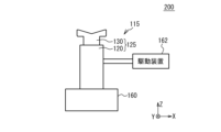
- FIG. 15 is a schematic diagram of a tactile sensation generation device according to Example 5.
- the normal direction of the upper surface of the pedestal 160 is the Z direction, and the directions orthogonal to the Z direction are the X direction and the Y direction.
- a vibrator 115 is provided on a pedestal 160.
- the vibrator 115 mainly vibrates in the Z direction.
- the vibrator 115 includes a housing 125 in which a first member 130 and a second member 120 are joined.
- the drive device 162 vibrates the vibrator 115 by applying a voltage to the vibrator 115.
- FIG. 16(a) is a plan view of the vibrator in Example 5, and FIG. 16(b) is a sectional view taken along line AA in FIG. 16(a).
- 17(a) is a plan view of the second member of the vibrator in Example 6
- FIG. 17(b) is a sectional view taken along line AA in FIG. 17(a)
- FIG. 17(c) is a plan view of the second member of the vibrator in Example 6.
- the direction in which the first member 130 and the second member 120 sandwich the piezoelectric elements 110a and 110b is the Z direction, which is orthogonal to the Z direction, and the extending directions of the sides of the piezoelectric elements 110a and 110b in plan view are the X direction and the Y direction.
- the housing 125 includes a first member 130 and a second member 120.
- the first member 130 and the second member 120 are joined.
- a recess 128 is provided on the surface of the second member 120 in the +Z direction.
- the recess 128 has a first portion 122 provided on the +Z side and a second portion 124 provided on the ⁇ Z side.
- the planar shape of the first portion 122 is approximately circular, and the planar shape of the second portion 124 is approximately rectangular.
- a thread 126 serving as a female thread is formed on the side surface of the first portion 122. No threads are formed on the side surface of the second portion 124.
- the support member 112a, the piezoelectric elements 110a and 110b, and the support member 112b are inserted into the recess 128 in this order from the ⁇ Z side.
- the support member 112a, the piezoelectric elements 110a, 110b, and the support member 112b are not joined to the second member 120 and are free to move.
- the first member 130 includes a head 132 provided on the +Z side and a threaded portion 134 provided on the -Z side.
- the planar shape of the head 132 is approximately circular.
- the +Z side surface of the head 132 has a center portion recessed in an inverted conical shape in the ⁇ Z direction with respect to the peripheral portion in plan view.
- a thread 136 which is a male thread, is formed on the side surface of the threaded portion 134.
- the threaded portion 134 of the first member 130 is joined to the first portion 122 of the recess 128 of the second member 120 by fitting the threads 126 and 136 together.
- the second member 120 presses the piezoelectric element 110a in the +Z direction as indicated by an arrow 150a via the support member 112a.
- the first member 130 presses the piezoelectric element 110b in the -Z direction as indicated by an arrow 150b via the support member 112b.
- the stress that presses the piezoelectric elements 110a and 110b is, for example, 5 ⁇ 10 6 Pa or more.
- the material of the first member 130 and the second member 120 is, for example, metal or resin.
- the material of the supporting members 112a and 112b has a larger Young's modulus than the first member 130, the second member 120, and the piezoelectric elements 110a and 110b, and is, for example, stainless steel.
- the width of the head 132 of the first member 130 in the X direction and the Y direction is, for example, 10 mm, and the height of the head 132 in the Z direction is, for example, 2.5 mm.
- the amount of recess is, for example, 1.5 mm
- the width of the threaded portion 134 in the X direction and the Y direction is, for example, 6 mm
- the height of the threaded portion 134 in the Z direction is, for example, 5 mm.
- the width of the second member 120 in the X direction and the Y direction is, for example, 8 mm
- the height is, for example, 15 mm
- the depth of the recess 128 in the Z direction is, for example, 14 mm
- the depth of the first portion 122 in the Z direction is, for example,
- the width of the second portion 124 in the X direction and the Y direction is, for example, 4.5 mm.
- the materials, shapes, and dimensions of the first member 130, the second member 120, and the support members 112a and 112b can be designed as appropriate.
- FIG. 18 is a cross-sectional view of the piezoelectric element in Example 5.
- the piezoelectric elements 110a and 110b include a piezoelectric body 140 made up of a plurality of piezoelectric layers 141, a plurality of first electrodes 142, and a plurality of second electrodes 144.
- the plurality of piezoelectric layers 141 are stacked in the Z direction.
- the piezoelectric layer 141, the first electrode 142, and the second electrode 144 have a flat plate shape extending in the XY plane.
- the plurality of first electrodes 142 and the plurality of second electrodes 144 are provided alternately in the Z direction.
- One piezoelectric layer 141 is sandwiched between one first electrode 142 and one second electrode 144 in the Z direction.
- a first external electrode 143 is provided on the side surface of the piezoelectric body 140 on the -X side, and a second external electrode 145 is provided on the side surface of the piezoelectric body 140 on the +X side.
- the plurality of first electrodes 142 are electrically connected to the first external electrode 143.
- the plurality of second electrodes 144 are electrically connected to the second external electrode 145.
- the piezoelectric body 140 includes a first region 146, a second region 147, and a third region 148.
- the first regions 146 and the second regions 147 are provided alternately in the Z direction.
- the third region 148 is provided outside the outermost first region 146 in the Z direction.
- the first region 146 is a region in which first electrodes 142 and second electrodes 144 are alternately provided at regular intervals in the Z direction.
- the number of stacked piezoelectric layers 141 in the first region 146 is, for example, 50 layers.
- the second region 147 and the third region 148 are regions where the first electrode 142 and the second electrode 144 are not provided.
- the second region 147 may not be provided. Reliability may be improved by providing the second region 147 in some cases.
- Examples of the material of the piezoelectric layer 141 include lead zirconate titanate (PZT:Pb(Zr,Ti)O 3 ), barium titanate-based material (BaTiO 3 , Ba may be Ca, Ti may be Zr), A bismuth titanate material (BiTiO 3 , in which part of Bi may be Na) or an alkali niobate material (NaNbO 3 , in which Na may be Li or K) can be used.
- metals such as Ag, Pd, Pt, Cu, Ni, and Au can be used, for example.
- the piezoelectric elements 110a and 110b are chips made of sintered bodies formed by laminating and sintering piezoelectric sheets each having a first electrode 142 and a second electrode 144 formed on their surfaces.
- the piezoelectric elements 110a and 110b are, for example, rectangular parallelepipeds, and the widths of the piezoelectric elements 110a and 110b in the X and Y directions are, for example, 3.5 mm, and the heights in the Z direction are, for example, 3 mm.
- the amount of displacement ⁇ Z in the Z direction on the surface of the ⁇ Z side of the piezoelectric elements 110a and 110b, the number of laminated piezoelectric layers 141 is N, the voltage applied between the first electrode 142 and the second electrode 144 is V, and the reverse If d33 is a constant related to the piezoelectric constant, ⁇ Z d33 ⁇ V ⁇ N. Therefore, by increasing the number N of stacked piezoelectric layers 141, the displacement amount ⁇ Z increases. However, due to manufacturing constraints or the like, it may not be possible to increase the number N of layers in one piezoelectric element 110a or 110b. In such a case, the piezoelectric elements 110a and 110b can be stacked in the Z direction within the housing 125. Thereby, the total amount of displacement of piezoelectric elements 110a and 110b can be increased.
- the number of piezoelectric elements 110a and 110b stacked in the Z direction may be one or three or more.
- FIG. 19 is a diagram showing a modulated wave that the drive device supplies to the piezoelectric element in Example 5.
- the horizontal axis in FIG. 19 shows time, and the vertical axis shows voltage.
- a signal with a carrier wave period T1 (frequency f1) is a carrier wave 164.
- An envelope 165 of the modulated wave 166 corresponds to a signal wave.
- the signal wave has a period T2 (frequency f2).
- a sine wave is used as the carrier wave 164, a triangular wave is shown as the carrier wave 164 for simplicity of illustration.
- the period T1 is much smaller than the period T2, the period T1 is illustrated in a larger size in FIG. 19 for easier understanding.
- the carrier wave 164 is amplitude-modulated by a signal wave.
- the carrier wave 164 is a sine wave
- the signal wave is a rectangular wave.
- the frequency f1 of the carrier wave 164 is, for example, the resonance frequency of the housing 125.
- the resonant frequency may be a fundamental wave or a harmonic.
- the frequency f2 of the signal wave is a frequency to which Meissner corpuscles, which are receptors in the human skin, are sensitive. Such a frequency is, for example, 1 Hz or more and 60 Hz or less.
- the modulation degree M of the modulated wave 166 is, for example, 50% or more and less than 100%.
- the rectangular wave is a waveform whose rise time and fall time are sufficiently smaller than the period T2.
- the rise time and fall time of the rectangular wave are, for example, 1/25 times or less and 1/100 times or less of the period T2.
- the Japanese Industrial Standard JIS C 161-02-05 applies mutatis mutandis to the definitions of the rise time and fall time.
- the rise time and fall time are the time when the voltage of the envelope 165 is 10% of the voltage and the time when the voltage is 90% for the difference between the voltages when the voltage of the envelope 165 is amplitude A1 and amplitude A2. This is the difference.
- the width of the head 132 of the first member 130 in the X and Y directions is 10 mm, the height of the head 132 in the Z direction is 2.5 mm, and the concave amount of the inverted conical apex of the +Z plane of the head 132 is 1.
- the width of the threaded portion 134 in the X and Y directions is 6mm, and the height of the threaded portion 134 in the Z direction is 5mm.
- the width of the second member 120 in the X and Y directions is 8 mm, the height is 15 mm, the depth of the recess 128 in the Z direction is 14 mm, the depth of the first portion 122 in the Z direction is 6 mm, and the The width in the direction and Y direction is 4.5 mm.
- Table 3 is a table showing the experimental conditions and results in Experiment 3.
- conditions A to I are conditions for a modulated wave that the driving device 162 supplies as a voltage between the first electrode 142 and the second electrode 144 of the piezoelectric elements 110a and 110b.
- “Waveform” is the waveform of the signal wave
- “rectangular wave” indicates that the waveform of the signal wave is a rectangular wave as shown in Figure 19
- “sine wave” indicates that the waveform of the signal wave is a sine wave.
- sawtooth wave indicates that the wavelength of the signal wave is a sawtooth wave (also referred to as a downward ramp wave) in which the wavelength of the signal wave has a steep fall and a gradual fall.
- “Carrier wave” is the frequency of carrier wave 164, which is 66 kHz in all conditions.
- the resonant frequency (second harmonic) of the housing 125 is 63.5 kHz.
- Signal wave is the frequency of the signal wave.
- modulation degree is the modulation degree M described with reference to FIG. 19, and all samples are 88%.
- Teactile sensation is the result of examining the softness of the tactile sensation when the first member 130 is touched.
- "1", “2", “3” and “4" represent the degree of soft tactile sensation, and the degree of soft tactile sensation decreases from “1” to "4".
- “1” provides the softest tactile sensation, and "4" provides no soft tactile sensation. When it is “1", it feels like touching a balloon.
- conditions A to G use a rectangular wave as the signal wave and change the frequency of the signal wave.
- the signal wave frequencies are 31 Hz and 3 Hz, a soft tactile sensation cannot be obtained.
- the frequency of the signal wave is 25Hz and 8Hz, a somewhat soft tactile sensation is obtained, when the frequency of the signal wave is 19Hz and 13Hz, a softer tactile sensation is obtained, and when the frequency of the signal wave is 16Hz, a soft tactile sensation is obtained most. It will be done.
- Condition H indicates the frequency (28 Hz) at which the softest tactile sensation was obtained by changing the frequency of the sine wave signal wave.
- Condition I indicates the frequency (21 Hz) at which the softest tactile sensation was obtained by changing the frequency of the sawtooth signal wave.
- the tactile sensation of the first member 130 was investigated while changing the frequency of the carrier wave 164 under condition D other than the frequency of the carrier wave 164.
- the soft tactile sensation remains almost unchanged.
- the frequency of the carrier wave 164 deviates from the range of ⁇ 14% of the resonant frequency, the soft tactile sensation is attenuated.
- the soft tactile sensation is attenuated as the frequency of the carrier wave 164 becomes further away from the resonant frequency.
- the tactile sensation of the first member 130 was investigated by changing the modulation degree M of the modulated wave 166 with the conditions other than the modulation degree being the same as condition D.
- the modulation degree M 100%, a soft tactile sensation cannot be obtained.
- the modulation degree M decreases, the soft tactile sensation becomes larger, and when the modulation degree M is 88%, the soft tactile sensation is the largest, and is a balloon-like tactile sensation.
- the modulation degree M is 70%
- the tactile sensation is almost the same as when the modulation degree M is 88%, but the tension of the balloon is slightly reduced.
- the modulation degree M is 50%, the soft tactile sensation decreases, giving the sensation of deflating a balloon.
- the modulation degree M 20%, a soft tactile sensation cannot be obtained.
- the driving device 162 transmits the carrier wave 164 having a frequency equal to the resonant frequency of the vibrator 115 by a signal wave that is a rectangular wave and has a frequency that is lower than the frequency of the carrier wave 164 and is felt by the Meissner corpuscles.
- Amplitude modulation is performed to generate a modulated wave 166 with a modulation degree M smaller than 100%, and the modulated wave 166 is supplied to the vibrator 115.
- the hard first member 130 is touched, it provides a soft tactile sensation.
- the frequency of the carrier wave 164 is preferably 0.86 times or more and 1.14 times or less than the resonant frequency of the vibrator 115 (i.e., the housing 125), and preferably 0.9 times or more and 1.14 times or less than the resonant frequency of the vibrator 115 (i.e., the housing 125). It is more preferably 1.1 times or less, and even more preferably 0.95 times or more and 1.05 times or less of the resonance frequency.
- the frequency of the signal wave is a frequency to which Meissner corpuscles are sensitive, and is preferably 1 Hz or more and 60 Hz or less, more preferably 3 Hz or more and 50 Hz or less, and even more preferably 13 Hz or more and 28 Hz or less.
- the modulation degree M of the modulated wave 166 is preferably 50% or more and 98% or less, more preferably 70% or more and 90% or less.
- the duty ratio (period/period T2 of amplitude A1) of the modulated wave 166 is preferably around 50%. The duty ratio may be 20% or more and 80% or less, 30% or more and 70% or less, or 40% or more and 60% or less.
- the vibrator 115 used in Example 5 uses piezoelectric elements 110a and 110b whose vibration mode is mainly a longitudinal displacement mode, and the housing 125 presses the piezoelectric elements 110a and 110b.
- the Q value is improved compared to when the housing 125 does not press the piezoelectric elements 110a and 110b.
- Such a phenomenon cannot be obtained when transverse displacement mode piezoelectric elements are used as the piezoelectric elements 110a and 110b, and is a phenomenon discovered for the first time by the inventors.
- the lateral displacement mode is a mode in which the vibration direction of the piezoelectric elements 110a and 110b is perpendicular to the lamination direction of the first electrode 142 and the second electrode 144.
- the resonance frequency does not vary much depending on whether or not the piezoelectric elements 110a and 110b are pressed. This is thought to be due to the provision of the support member 112a.
- the first electrode 142 and the second electrode 144 sandwich the piezoelectric layer 141 in the Z direction, and a voltage is applied between the first electrode 142 and the second electrode 144. Therefore, piezoelectric elements 110a and 110b that expand and contract in the Z direction are used.
- the first member 130 and the second member 120 press the piezoelectric element 110a in the Z direction, and the first member 130 generates vibrations corresponding to the expansion and contraction of the piezoelectric elements 110a and 110b in the Z direction. Output.
- the housing 125 presses the vertical displacement piezoelectric elements 110a and 110b, thereby improving the Q value of the mechanical vibration of the housing 125. Therefore, the characteristics of the tactile sensation generating device can be improved.
- the first member 130 and the second member 120 press the piezoelectric elements 110a and 110b by fitting screws together.
- piezoelectric elements 110a and 110b can be stably pressed with a large force.
- variations in the pressure applied to the piezoelectric elements 110a and 110b can be suppressed. Therefore, variations in resonance frequency, etc. can be suppressed.
- the variation in resonance frequency was 600 Hz or less.
- the mechanism for pressing the piezoelectric elements 110a and 110b may be other than screw fitting.
- Example 5 when the nominal diameter d (maximum diameter) of the thread 136 of the first member 130 was 6 mm, the tightening torque T of the first member 130 was measured using a torque wrench and was approximately 0.1 N ⁇ m. .
- the area of the piezoelectric elements 110a and 110b in the XY plane is 3.5 mm x 3.5 mm. Therefore, the pressure with which the first member 130 presses the piezoelectric element 110b is 6.8 ⁇ 10 6 Pa.
- the pressure with which the first member 130 and the second member 120 press the piezoelectric elements 110a and 110b is preferably 5 ⁇ 10 5 Pa or more, more preferably 1 ⁇ 10 6 Pa or more, and even more preferably 2 ⁇ 10 6 Pa or more. preferable.
- a support member 112b (third member) is provided between the first member 130 and the piezoelectric element 110b, and a support member 112a (fourth member) is provided between the second member 120 and the piezoelectric element 110a. At least one of support members 112a and 112b may be provided.
- the Young's modulus of PZT is approximately 60 GPa.
- resin is used as the housing 125, the Young's modulus of the resin is 10 GPa or less.
- stainless steel is used as the support members 112a and 112b
- the Young's modulus of stainless steel is about 120 GPa.
- the Young's modulus of aluminum is approximately 70 GPa.
- the Young's modulus of the supporting member 112b is greater than the Young's modulus of the piezoelectric body 140 and the Young's modulus of the first member 130, and the Young's modulus of the supporting member 112b is greater than the Young's modulus of the piezoelectric body 140 and the Young's modulus of the second member 120. greater than the rate.
- the support members 112a and 112b By providing the support members 112a and 112b, a load is applied to the piezoelectric elements 110a and 110b, and vibration transmission can be strengthened. Therefore, variation in the resonance frequency of the housing 125 due to pressure is suppressed, and the Q value is further improved. At least one of support members 112a and 112b may be provided.
- the Young's modulus of the supporting members 112b and 112a is preferably 1.2 times or more, more preferably 1.5 times or more, the Young's modulus of the piezoelectric body 140 and the Young's modulus of the first member 130 and the second member 120, respectively.
- the plurality of first electrodes 142 and the plurality of second electrodes 144 are provided alternately in the Z direction, and one of the plurality of piezoelectric layers 141 is It is sandwiched between one of the electrodes 142 and one of the plurality of second electrodes 144 in the Z direction.
- the amount of displacement in the Z direction can be increased, and the characteristics of the tactile sensation generating device can be further improved.
- FIG. 20(a) and 20(b) are cross-sectional views showing another example of the second member in Example 5.
- the +Z side surface of the head 132 of the first member 130 is flat.
- the peripheral portion of the +Z side surface of the head 132 of the first member 130 is inclined in the -Z direction.
- a different tactile sensation can be obtained.
- FIG. 20(a) and FIG. 20(b) by using a first member 130 in which the +Z side surface is flat or expands in the +Z direction, it is possible to obtain the tactile sensation of a soft balloon such as bubble wrap.
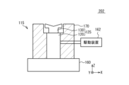
- FIG. 21 is a schematic diagram of a tactile sensation generating device according to Modification 1 of Example 5.
- the vibrator 115 is shown in a side view, and the member 170 is shown in a cross section.
- the second member 120 of the vibrator 115 is fitted into the member 170, and the first member 130 is surrounded by the member 170.
- Member 170 is not in contact with first member 130.
- the member 170 is made of resin that is softer than the first member 130. Vibration of the second member 120 is transmitted to the member 170 by the member 170 coming into contact with the second member 120 . This allows the member 170 to have a soft tactile sensation.
- FIG. 22(a) is a sectional view of the first member of the vibrator in Example 6, and FIG. 22(b) is a sectional view of the second member of the vibrator in Example 6.
- the first member 130 of the vibrator 115 in Example 6 is provided with a groove 133 on the +Z side surface.
- the other configurations are the same as the first member of Example 5.
- the second member 120 of the vibrator 115 in the sixth embodiment is larger than the second member in the fifth embodiment.
- a hole 127b passing through the second member 120 in the Y direction is provided in the -Z direction of the recess 128.
- the cross-sectional shape of the hole 127b is circular.
- a screw hole 127a for screwing to the pedestal is provided on the -Z side surface of the second member 120.
- the other configurations are the same as the first member of Example 5.
- the shape and material of the casing 125 of the vibrator 115 can be selected as appropriate.
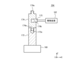
- FIG. 23 is a schematic diagram of a tactile sensation generation device in Example 7. A portion of the haptic sensation generating device 204 is illustrated in cross section.
- a joint member 172 is fixed to the base 160.
- the joint member 172 has a cylindrical shape that is elongated in the vertical direction.
- a screw hole 172a is provided on the upper surface of the joint member 172.
- the member 174 has a cylindrical shape that is long in the vertical direction. Threaded portions 174a are provided on the upper and lower surfaces of the member 174.
- the member 174 is fixed to the joint member 172 by screwing the threaded portion 174a into the screw hole 172a.
- a hole 174b extending in the horizontal direction is formed in the member 174.
- the vibrator 115 of the fifth embodiment is embedded and fixed in the hole 174b.
- the drive device 162 supplies a modulated wave 166 between the first electrode 142 and the second electrode 144 of the piezoelectric elements 110a and 110b of the vibrator 115, as shown in FIG.
- a soft tactile sensation can be obtained from the member 174 by gripping the member 174 in a horizontal direction.
- the other configurations are the same as those of the fifth embodiment, and the explanation will be omitted.
- member 170 or 174 is in contact with at least a portion of casing 125 (for example, second member 120 in Modified Example 1 of Embodiment 5), and the member 170 or 174 is in contact with at least a portion of casing 125.
- Softer That is, the Young's modulus of the member 170 or 174 is smaller than the Young's modulus of the housing 125. As a result, vibrations are transmitted to the member 170 or 174 from the portion in contact with the housing 125. Touching member 170 or 174 provides a soft tactile sensation.
- FIG. 24(a) is a plan view of the tactile sensation generating device in Example 7, and FIG. 24(b) is a sectional view taken along line AA in FIG. 24(a).
- the extending directions of the long side and short side of the vibrator 115a in a plan view are respectively the X direction and the Y direction, and the normal direction of the top surface of the vibrator 115a is the Z direction.
- the vibrator 115a has a rectangular planar shape (a rectangular shape in which the long side is much longer than the short side).
- a member 176 covers and contacts the vibrator 115a.
- the planar shape of the member 176 is also a rectangular shape.
- Member 176 is softer than vibrator 115a.
- the drive device 162 supplies a modulated wave 166 as shown in FIG. 19 to the vibrator 115a. As a result, vibration corresponding to the modulated wave 166 is generated in the vibrator 115a.
- the vibration of the vibrator 115 is in the X direction as indicated by an arrow 156.
- FIG. 25 is a cross-sectional view of the vibrator in Example 8.
- the vibrator 115a is a piezoelectric element 110.
- the piezoelectric element 110 includes a piezoelectric body 140 made up of a plurality of piezoelectric layers 141, a plurality of first electrodes 142, and a plurality of second electrodes 144.
- the plurality of first electrodes 142 and the plurality of second electrodes 144 are provided alternately in the Z direction.
- One piezoelectric layer 141 is sandwiched between one first electrode 142 and one second electrode 144 in the Z direction.
- a first external electrode 143 to which the first electrode 142 is electrically connected is provided on the side surface of the piezoelectric body 140 on the ⁇ X side.
- a second external electrode 145 is provided on the +X side side surface of the piezoelectric body 140 to which the second electrode 144 is electrically connected.
- the planar shape of the piezoelectric element 110 is a long strip in the X direction
- the piezoelectric element 140 moves as shown by the arrow 156. It expands and contracts in the X direction.
- the vibration mode that expands and contracts in the plane direction by applying a voltage to the first electrode 142 and the second electrode 144 in this way is called a lateral displacement mode or d31 mode.
- the vibrator 115a may be a piezoelectric element 110 that mainly vibrates in a lateral displacement mode. Further, the vibrator 115a may not include the housing 125 and the piezoelectric element 110 may be in direct contact with the member 176. A piezoelectric element that mainly vibrates in a longitudinal displacement mode may be in direct contact with the member 176. Further, the vibrator may be vibrated by a mechanism other than the piezoelectric element. These tactile sensation generating devices can also generate a soft tactile sensation.
Landscapes
- Engineering & Computer Science (AREA)
- Physics & Mathematics (AREA)
- Mechanical Engineering (AREA)
- Acoustics & Sound (AREA)
- Signal Processing (AREA)
- Electromagnetism (AREA)
- Apparatuses For Generation Of Mechanical Vibrations (AREA)
Abstract
Description
を備える構成とすることができる。
第2部材20の形状を変え、空中触覚を調査した。
実験した各部材の材料は以下である。
圧電素子10aおよび10b
圧電体40の材料はPZT
X方向およびY方向の幅:3.5mm
Z方向の高さ:3mm
第1領域46における圧電体層41の積層数:50
第1領域46の個数:3個
支持部材12aの材料:ステンレス
第1部材30の材料:アクリル樹脂
第2部材20の材料:アクリル樹脂


図7は、実施例2の変形例1において駆動装置が圧電素子に供給する変調波を示す図である。図7における横軸は時間を示し、縦軸は電圧を示している。実施例2の変形例1では、周期T2(周波数f2)の第2搬送波を周期T3(周波数f3)の信号波により振幅変調し第1変調波を生成する。周期T1(周波数f1)の第1搬送波を、振幅変調された第1変調波により振幅変調し第2変調波66とする。包絡線65aは、信号波と第2搬送波が重畳された波形となる。第1搬送波64の周波数f1は、筐体25の共振周波数(例えば共振周波数の0.86倍以上かつ1.14倍以下)であり、例えば20kHz~110kHzである。第2搬送波の周波数f2は、パチニ小体に敏感な周波数であり、例えば50Hz~300Hzである。信号波の周波数f3は、人体の皮膚の受容器であるマイスナー小体に敏感な周波数であり、例えば1Hz~60Hzである。その他の構成は実施例2と同じであり説明を省略する。
実施例2の変形例2は、実施例1の振動発生素子100を複数設ける例である。図8は、実施例2の変形例2に係る振動発生装置の模式図である。図8示すように、実施例2の変形例2の振動発生装置102では、台座60上に実施例1の複数の振動発生素子100が固定されている。駆動装置62は、変調波を複数の振動発生素子100に出力する。複数の振動発生素子100は、第1部材30からZ方向に音波54を放出する。複数の振動発生素子100の第1部材30の+Z方向に人体の一部をかざすと、複数の音波54により触覚がより得られる。駆動装置62は、同じ波形の変調波を複数の振動発生素子100に出力してもよいし、異なる波形の変調波を複数の振動発生素子100に出力してもよい。振動発生素子100の個数は、適宜設定できる。その他の構成は実施例2と同じであり説明を省略する。
実施例4の変形例1は、実施例4の振動発生素子104をスピーカ等の振動発生装置に用いる例である。図12は、実施例4の変形例1に係る振動発生装置の模式図である。
被押当部材72の上面における振動発生素子から一定の距離の箇所における振動の振幅を測定した。
条件F:実施例1の振動発生素子100、押当部材70を設けない
条件G:実施例4の振動発生素子104、押当部材70を設けない
条件H:実施例4の振動発生素子104、押当部材70を設ける
第1部材30aおよび第2部材30bは図6(a)の部材Bの形状であり、材料はステンレス(SUS401:ヤング率が約200GPa)である。被押当部材72および押当部材70の材料はステンレスである。押当部材70の重さは約200gである。その他の各部材の材料および寸法は実施例1と同じである。駆動装置62が圧電素子10aおよび10bに供給する電圧は、周波数が250Hzの正弦波である。
実施例3の図9における振動発生素子100の代わりに実施例4の振動発生素子104を用い、被押当部材72をガラス板として、押当部材70として、図10(a)および図10(b)の押当部材70を用いた。押当部材70の重さは約1kgである。低音域および中音域を市販の電磁スピーカにより再生し、高音域の再生に実施例4の変形例2の振動発生装置を用いた。音響システムにおいて、鳥の囀りおよびサックスの楽曲について、再生の全帯域において再生が可能であり、クリアーな音響の再生が可能であった。
図14は、実施例4の変形例3に係る振動発生装置の模式図である。図14に示すように、実施例4の変形例3の振動発生装置106では、板材76に貫通孔76aが設けられ、貫通孔76a内に実施例4の振動発生素子104が埋め込まれている。板材76の一方の面から第1部材30aが突出し、板材76の他方の面から第2部材30bが突出する。駆動装置62が振動発生素子104に、図5のような電圧を供給する。これにより、矢印54aおよび54bのように、板材76の両方向に音波を放出することが可能となる。振動発生素子104を用いることで、空中触覚を大きくできる。また、2つの方向に音波を放出することができる。
第1部材130の+Z側の触覚の柔軟性を調査した。
実験した各部材の材料は以下である。
圧電素子110aおよび110b
圧電体140の材料はPZT
第1電極142および第2電極144の材料は銀-パラジウム
X方向およびY方向の幅:3.5mm
Z方向の高さ:3mm
第1領域146における圧電体層141の積層数:50
第1領域146の個数:3個
支持部材112aの材料:ステンレス
第1部材130の材料:アクリル樹脂
第2部材120の材料:アクリル樹脂
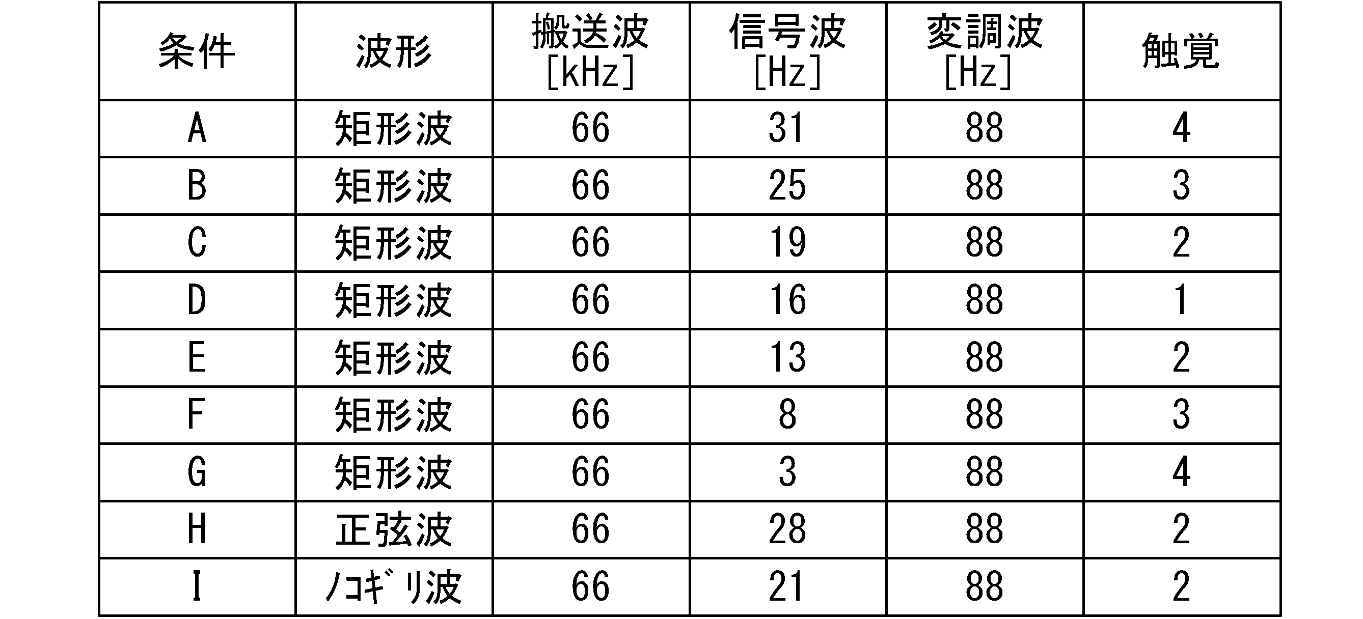
図21は、実施例5の変形例1の触覚生成装置の模式図である。振動器115は側面を部材170は断面を図示している。図21に示すように、実施例5の変形例1の触覚生成装置202では、振動器115の第2部材120を部材170にはめ込み、第1部材130の周りを部材170が囲んでいる。部材170は第1部材130には接触していない。部材170は第1部材130より柔らかい樹脂である。部材170が第2部材120に接触することで、第2部材120の振動は部材170に伝達される。これにより、部材170に柔らかい触覚を生じさせることができる。
Claims (22)
- 圧電体層と、前記圧電体層を挟む第1電極および第2電極と、を備え、前記第1電極と前記第2電極との間に電圧を印加することで前記第1電極および前記第2電極が前記圧電体層を挟む方向に伸縮する圧電素子と、
前記圧電素子を前記方向において挟む第1部材および第2部材を備え、前記第1部材と前記第2部材とは前記圧電素子を前記方向に押圧し、前記第1部材は前記方向に前記圧電素子の伸縮に対応する音波を出力する筐体と、
を備える振動発生装置。 - 前記第1部材と前記第2部材とは、前記第1部材に設けられたねじ山と前記第2部材に設けられたねじ山とを嵌め合わせることにより前記圧電素子を押圧する請求項1に記載の振動発生装置。
- 前記第1部材と前記第2部材とが接合する第3部材を備え、
前記第1部材に設けられたねじ山と前記第3部材に設けられたねじ山とを嵌め合わせ、かつ前記第2部材に設けられたねじ山と前記第3部材に設けられたねじ山とを嵌め合わせることにより、前記第1部材と前記第2部材とは、前記圧電素子を押圧する請求項1に記載の振動発生装置。 - 前記第1部材と前記圧電素子との間に設けられ、前記第1部材のヤング率および前記圧電体層のヤング率より大きなヤング率を有する第4部材と、前記第2部材と前記圧電素子との間に設けられ、前記第2部材のヤング率および前記圧電体層のヤング率より大きなヤング率を有する第5部材と、の少なくとも一方の部材を備える請求項1から3のいずれか一項に記載の振動発生装置。
- 前記第1部材および前記第2部材が前記圧電素子を押圧する圧力は、5×10⁵Pa以上である請求項1から3のいずれか一項に記載の振動発生装置。
- 前記圧電体層、前記第1電極および前記第2電極は各々複数設けられ、前記複数の第1電極および前記第2電極は前記方向において互い違いに設けられ、前記複数の圧電体層の1つは、前記複数の第1電極のうち1つと前記複数の第2電極のうち1つに前記方向において挟まれる請求項1から3のいずれか一項に記載の振動発生装置。
- 前記第1部材は、前記方向の空間に前記音波を出力し、
前記圧電素子に、前記電圧として前記筐体の共振周波数の0.86倍以上かつ1.14倍以下の周波数を有する搬送波を前記搬送波の周波数より低い周波数を有する信号波により振幅変調させた変調波が供給される請求項1から3のいずれか一項に記載の振動発生装置。 - 前記信号波の周波数は70Hz以上かつ1000Hz以下である請求項7に記載の振動発生装置。
- 前記第1部材は、前記方向の空間に前記音波を出力し、
前記圧電素子に、前記電圧として、前記筐体の共振周波数の0.86倍以上かつ1.14倍以下の周波数を有する第1搬送波を、50Hz以上かつ300Hz以下である周波数を有する第2搬送波を1Hz以上かつ60Hz以下である周波数を有する信号波で振幅変調された第1変調波で、振幅変調された第2変調波を供給する請求項1から3のいずれか一項に記載の振動発生装置。 - 前記第1部材の前記空間側の面は、中央部が前記圧電素子の方に凹む請求項7に記載の振動発生装置。
- 前記圧電素子に、前記電圧として前記変調波を供給する駆動装置を備える請求項7に記載の振動発生装置。
- 前記第1部材の前記方向における表面を被押当部材に押当てることで前記被押当部材から音波が発生するように、前記圧電素子に前記電圧が供給される請求項1から3のいずれか一項に記載の振動発生装置。
- 前記第1部材の前記表面を前記被押当部材に押当てる押当部材と、
前記圧電素子に前記電圧を供給する駆動装置と、
を備える請求項12に記載の振動発生装置。 - 振動器と、
前記振動器の共振周波数の0.86倍以上かつ1.14倍以下の周波数を有する搬送波を前記搬送波の周波数より低く1Hz以上かつ60Hz以下の周波数を有し矩形波である信号波により振幅変調させ、変調度が50%以上かつ100%より小さい変調波を生成して、前記振動器に前記変調波を供給する駆動装置と、
を備える触覚生成装置。 - 前記振動器は、
圧電体層と、前記圧電体層を挟む第1電極および第2電極と、を備え、前記第1電極と前記第2電極との間に電圧を印加することで前記第1電極および前記第2電極が前記圧電体層を挟む方向に伸縮する圧電素子と、
前記圧電素子を前記方向において挟む第1部材および第2部材を備え、前記第1部材と前記第2部材とは前記圧電素子を前記方向に押圧し、前記圧電素子の伸縮に対応する振動を出力する筐体と、
を備える請求項14に記載の触覚生成装置。 - 前記第1部材と前記第2部材とは、ねじを嵌め合わせることにより前記圧電素子を押圧する請求項15に記載の触覚生成装置。
- 前記第1部材と前記圧電素子との間に設けられ、前記第1部材のヤング率および前記圧電体層のヤング率より大きなヤング率を有する第3部材と、前記第2部材と前記圧電素子との間に設けられ、前記第2部材のヤング率および前記圧電体層のヤング率より大きなヤング率を有する第4部材と、の少なくとも一方の部材を備える請求項15または16に記載の触覚生成装置。
- 前記第1部材および前記第2部材が前記圧電素子を押圧する圧力は、5×10⁵Pa以上である請求項16または17に記載の触覚生成装置。
- 前記圧電体層、前記第1電極および前記第2電極は各々複数設けられ、前記複数の第1電極および前記第2電極は前記方向において互い違いに設けられ、前記複数の圧電体層の1つは、前記複数の第1電極のうち1つと前記複数の第2電極のうち1つに前記方向において挟まれる請求項16または17に記載の触覚生成装置。
- 前記筐体の少なくとも一部分に接し、前記少なくとも一部分から振動が伝達し、前記少なくとも一部分より柔らかい部材を備える請求項16に記載の触覚生成装置。
- 前記変調度は98%以下である請求項14または15に記載の触覚生成装置。
- 前記信号波の周波数は3Hz以上かつ50Hz以下である請求項14または15に記載の触覚生成装置。
Priority Applications (1)
| Application Number | Priority Date | Filing Date | Title |
|---|---|---|---|
| CN202380066270.XA CN119895896A (zh) | 2022-09-14 | 2023-07-04 | 振动产生装置和触觉生成装置 |
Applications Claiming Priority (4)
| Application Number | Priority Date | Filing Date | Title |
|---|---|---|---|
| JP2022-146290 | 2022-09-14 | ||
| JP2022146290A JP2024041460A (ja) | 2022-09-14 | 2022-09-14 | 振動発生装置 |
| JP2022-150411 | 2022-09-21 | ||
| JP2022150411A JP2024044707A (ja) | 2022-09-21 | 2022-09-21 | 触覚生成装置 |
Publications (1)
| Publication Number | Publication Date |
|---|---|
| WO2024057679A1 true WO2024057679A1 (ja) | 2024-03-21 |
Family
ID=90274564
Family Applications (1)
| Application Number | Title | Priority Date | Filing Date |
|---|---|---|---|
| PCT/JP2023/024763 Ceased WO2024057679A1 (ja) | 2022-09-14 | 2023-07-04 | 振動発生装置および触覚生成装置 |
Country Status (2)
| Country | Link |
|---|---|
| CN (1) | CN119895896A (ja) |
| WO (1) | WO2024057679A1 (ja) |
Citations (4)
| Publication number | Priority date | Publication date | Assignee | Title |
|---|---|---|---|---|
| JPS6373181U (ja) * | 1986-10-29 | 1988-05-16 | ||
| JP2005136863A (ja) * | 2003-10-31 | 2005-05-26 | Fujitsu Ten Ltd | 板体直接駆動スピーカ装置 |
| JP2009077130A (ja) * | 2007-09-20 | 2009-04-09 | Ngk Spark Plug Co Ltd | 超音波振動子 |
| CN202778922U (zh) * | 2012-08-30 | 2013-03-13 | 宁波新芝生物科技股份有限公司 | 一种大功率超声波换能组件及换能器 |
-
2023
- 2023-07-04 CN CN202380066270.XA patent/CN119895896A/zh active Pending
- 2023-07-04 WO PCT/JP2023/024763 patent/WO2024057679A1/ja not_active Ceased
Patent Citations (4)
| Publication number | Priority date | Publication date | Assignee | Title |
|---|---|---|---|---|
| JPS6373181U (ja) * | 1986-10-29 | 1988-05-16 | ||
| JP2005136863A (ja) * | 2003-10-31 | 2005-05-26 | Fujitsu Ten Ltd | 板体直接駆動スピーカ装置 |
| JP2009077130A (ja) * | 2007-09-20 | 2009-04-09 | Ngk Spark Plug Co Ltd | 超音波振動子 |
| CN202778922U (zh) * | 2012-08-30 | 2013-03-13 | 宁波新芝生物科技股份有限公司 | 一种大功率超声波换能组件及换能器 |
Also Published As
| Publication number | Publication date |
|---|---|
| CN119895896A (zh) | 2025-04-25 |
Similar Documents
| Publication | Publication Date | Title |
|---|---|---|
| JP5327317B2 (ja) | 圧電アクチュエータおよび音響部品 | |
| CN113453808B (zh) | 具有放大的变形的压电致动器 | |
| EP2597894A1 (en) | Vibration device and electronic device | |
| WO2005094121A1 (ja) | 圧電音響素子、音響装置及び携帯端末装置 | |
| JP3873990B2 (ja) | 超音波トランスデューサ及びこれを用いた超音波スピーカ | |
| JP2005354582A (ja) | 超音波トランスデューサ及びこれを用いた超音波スピーカ | |
| JP7253094B1 (ja) | 圧電スピーカ | |
| JP2005117103A (ja) | 超音波トランスデューサ | |
| JP2024041460A (ja) | 振動発生装置 | |
| WO2023199624A1 (ja) | 触覚発生装置、触覚発生システム及び触覚発生装置の駆動方法 | |
| WO2024057679A1 (ja) | 振動発生装置および触覚生成装置 | |
| JP5029948B2 (ja) | 超音波モータ | |
| JP4352922B2 (ja) | 超音波トランスデューサ | |
| KR101544834B1 (ko) | 압전진동발생기 | |
| JP2024044707A (ja) | 触覚生成装置 | |
| JP6020465B2 (ja) | 発振装置 | |
| JP2024135014A (ja) | 振動発生装置 | |
| JP4899590B2 (ja) | 静電型スピーカ | |
| WO2026004331A1 (ja) | 振動発生装置 | |
| KR20100077958A (ko) | 압전 스피커 | |
| JP2021164915A (ja) | 圧電振動装置 | |
| EP4501473A1 (en) | Transducer including piezoelectric element and method of producing same | |
| WO2025204643A1 (ja) | 振動発生装置 | |
| JP2024137134A (ja) | 振動発生装置 | |
| JP6382707B2 (ja) | 音響発生器およびこれを備えたスピーカー |
Legal Events
| Date | Code | Title | Description |
|---|---|---|---|
| 121 | Ep: the epo has been informed by wipo that ep was designated in this application |
Ref document number: 23865041 Country of ref document: EP Kind code of ref document: A1 |
|
| WWE | Wipo information: entry into national phase |
Ref document number: 202380066270.X Country of ref document: CN |
|
| NENP | Non-entry into the national phase |
Ref country code: DE |
|
| WWP | Wipo information: published in national office |
Ref document number: 202380066270.X Country of ref document: CN |
|
| 122 | Ep: pct application non-entry in european phase |
Ref document number: 23865041 Country of ref document: EP Kind code of ref document: A1 |