WO2024053724A1 - 信号処理装置、信号処理方法及びプログラム - Google Patents
信号処理装置、信号処理方法及びプログラム Download PDFInfo
- Publication number
- WO2024053724A1 WO2024053724A1 PCT/JP2023/032792 JP2023032792W WO2024053724A1 WO 2024053724 A1 WO2024053724 A1 WO 2024053724A1 JP 2023032792 W JP2023032792 W JP 2023032792W WO 2024053724 A1 WO2024053724 A1 WO 2024053724A1
- Authority
- WO
- WIPO (PCT)
- Prior art keywords
- phase noise
- signal
- measurement target
- zero
- signal processing
- Prior art date
- Legal status (The legal status is an assumption and is not a legal conclusion. Google has not performed a legal analysis and makes no representation as to the accuracy of the status listed.)
- Ceased
Links
Images



Classifications
-
- G—PHYSICS
- G01—MEASURING; TESTING
- G01R—MEASURING ELECTRIC VARIABLES; MEASURING MAGNETIC VARIABLES
- G01R19/00—Arrangements for measuring currents or voltages or for indicating presence or sign thereof
- G01R19/06—Measuring real component; Measuring reactive component
-
- G—PHYSICS
- G01—MEASURING; TESTING
- G01R—MEASURING ELECTRIC VARIABLES; MEASURING MAGNETIC VARIABLES
- G01R19/00—Arrangements for measuring currents or voltages or for indicating presence or sign thereof
- G01R19/175—Indicating the instants of passage of current or voltage through a given value, e.g. passage through zero
-
- G—PHYSICS
- G01—MEASURING; TESTING
- G01R—MEASURING ELECTRIC VARIABLES; MEASURING MAGNETIC VARIABLES
- G01R23/00—Arrangements for measuring frequencies; Arrangements for analysing frequency spectra
- G01R23/16—Spectrum analysis; Fourier analysis
Definitions
- the present invention relates to a signal processing device, a signal processing method, and a program.
- phase noise has been known as one of the evaluation indicators of the performance (e.g. frequency stability) of devices to be measured such as crystal oscillators, audio equipment, digital equipment, communication equipment, etc.
- Various methods of measurement are being considered.
- the signal to be measured output from the device under test is measured using two independent measuring instruments, and each of the two measuring instruments is A cross-correlation spectrum method is known in which the phase noise of the DUT is measured by removing the phase noise of each of the two measuring instruments by taking the cross-correlation spectrum of the measurement signal of the DUT (for example, Patent Document 1). Note that the cross-correlation spectrum is also called a cross spectrum.
- one of the objects of the present disclosure is to provide a signal processing device, a signal processing method, and a program that can measure the phase noise of a device to be measured while reducing at least one of measurement cost and measurement time.
- a signal processing device includes an acquisition unit that acquires a plurality of measurement target signals obtained by independently analog-to-digital conversion of a measurement target signal output from a measurement target device by a plurality of measuring instruments; a derivation unit that derives a plurality of zero-crossing fluctuations (ZCF), which are time differences between the zero-crossing time of each measurement target signal and the zero-crossing time of an ideal sine wave signal; A calculation unit that calculates phase noise of the device to be measured.
- ZCF zero-crossing fluctuations
- a signal processing device acquires a plurality of measurement target signals output from a measurement target device and each independently analog-to-digital converted by a plurality of measuring instruments, Deriving a plurality of zero-crossing fluctuations (ZCFs), which are time differences between the zero-crossing times of each of the plurality of measurement target signals and the zero-crossing time of an ideal sine wave signal, and based on the plurality of ZCFs, performing the measurement. Calculate the phase noise of the target device.
- ZCFs zero-crossing fluctuations
- a program includes an acquisition unit that causes a computer to acquire a plurality of measurement target signals outputted from a measurement target device and independently analog-to-digital converted by a plurality of measurement devices; a derivation unit that derives a plurality of zero-crossing fluctuations (ZCFs), which are time differences between the zero-crossing times of each of the plurality of measurement target signals and the zero-crossing time of an ideal sine wave signal; and based on the plurality of ZCFs, It functions as a calculation unit that calculates the phase noise of the device to be measured.
- ZCFs zero-crossing fluctuations
- phase noise of a device it is possible to measure the phase noise of a device to be measured while reducing at least one of measurement cost and measurement time.
- FIG. 1 is a diagram showing an example of the configuration of a measurement system according to the present embodiment.
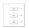
- 1 is a diagram illustrating an example of the configuration of a signal processing device according to an embodiment.
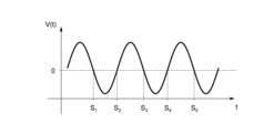
- FIG. 3 is a diagram showing an example of zero-crossing time of a signal to be measured according to the present embodiment. It is a figure showing an example of ZCF concerning this embodiment. It is a figure showing an example of setting for ZCF derivation concerning this embodiment. It is a figure showing other examples of settings for ZCF derivation concerning this embodiment. It is a flowchart which shows an example of operation of the measurement system concerning this embodiment.
- FIG. 1 is a diagram showing an example of the configuration of a measurement system according to the present embodiment.
- 1 is a diagram illustrating an example of the configuration of a signal processing device according to an embodiment.
- FIG. 3 is a diagram showing an example of zero-crossing time of a signal to be measured according to the present embodiment. It is a figure showing an example of ZCF concerning this embodiment. It
- 3 is a diagram illustrating an example of a comparison between phase noise measured by the signal processing device 50 according to the present embodiment and phase noise measured using a cross-correlation spectrum method.
- 1 is a diagram illustrating an example of generalization of the configuration of a measurement system according to the present embodiment.
- the measurement system includes a device to be measured (hereinafter referred to as "DUT: Device Under Test”), a divider that distributes a signal to be measured output from the DUT, and a divider connected to the divider. It includes a plurality of measuring instruments and a signal processing device connected to the plurality of measuring instruments.
- DUT Device Under Test
- N the number of multiple measuring devices
- N the number of multiple measuring devices
- FIG. 1 is a diagram showing an example of the configuration of a measurement system according to the present embodiment.
- N 2
- the measurement system 1 includes a DUT 10, a distributor 20, two independent analog-to-digital converters (ADCs) 30a and 30b, and an ADC 30a. and 30b, and a signal processing device 50.
- ADCs analog-to-digital converters
- the measuring device MDa includes an ADC 30a and a clock circuit 40a
- the measuring device MDb includes an ADC 30b and a clock circuit 40b.
- the measuring devices MDa and b are not distinguished, they will simply be collectively referred to as measuring devices MD.
- the ADCs 30a and 30b are not distinguished, they are collectively referred to as the ADC 30, and when the clock circuits 40a and 40b are not distinguished, they are collectively referred to as the clock circuit 40.
- FIG. 1 is merely an example, and some configurations may be omitted, configurations not shown may be added, or the arrangement of some configurations may be changed.
- a plurality of measuring devices MD may be connected in parallel without providing the distributor 20.
- the DUT 10 is an oscillator that outputs a periodic signal such as a sine wave or a rectangular wave as a signal to be measured.
- the DUT 10 includes, for example, a crystal oscillator, a voltage controlled oscillator (VCO), a temperature compensated crystal oscillator (TCXO), and an oven controlled crystal oscillator (OCXO). ), audio equipment such as audio players and music players with earphone output terminals, communication equipment such as wireless communication terminals or base stations, arbitrary waveform generators with BNC (Bayonet Neill Concelman) output terminals, etc. be.
- VCO voltage controlled oscillator
- TXO temperature compensated crystal oscillator
- OXO oven controlled crystal oscillator
- the distributor 20 is, for example, a power splitter, and distributes the measurement target signal output from the DUT 10 and outputs the distributed measurement target signal to each ADC 30.
- Each ADC 30 measures the measurement target signal output from the distributor 20. Specifically, each ADC 30 samples the measurement target signal output from the distributor 20 based on the clock signal output from the corresponding clock circuit 40, and converts it from an analog signal to a digital signal (discrete data). You may.
- Each clock circuit 40 generates a clock signal and outputs the generated clock signal to the corresponding ADC 30.
- Each clock circuit 40 may be, for example, an oscillator such as a crystal oscillator, a VCO, a TCXO, or an OCXO.
- the clock signal may be a periodic signal with a predetermined frequency (eg, 27 MHz).
- a clock signal is also called a reference signal or a local signal.
- Each measuring device MD including the ADC 30 and the clock circuit 40 may be, for example, an audio device such as an audio recorder, or a communication device such as a base station or a wireless communication terminal. Note that each measuring device MD does not need to include the clock circuit 40, but may include at least the ADC 30.
- the measurement of the measurement target signal in each measuring device MD may include conversion from an analog signal to a digital signal by the ADC 30.
- the signal processing device 50 calculates the phase noise of the DUT 10 based on the measurement target signal output from each measuring device MD.
- the signal processing device 50 is composed of a device including at least a processor.
- phase noise is a variation in phase or frequency of a signal to be measured.
- jitter is a fluctuation in a signal waveform in the time direction.
- the phase noise calculated by the signal processing device 50 may include at least one of PI (Phase independent) noise, jitter, and amplitude modulation (AM).
- FIG. 2 is a diagram showing an example of the configuration of the signal processing device 50 according to the present embodiment.
- the signal processing device 50 includes an acquisition section 501, a derivation section 502, and a calculation section 503.
- the configuration of the signal processing device 50 is realized by, for example, at least one of a processor and a program executed by the processor.
- the acquisition unit 501 acquires a plurality of measurement target signals respectively output from a plurality of measuring devices MD. For example, in FIG. 1, the acquisition unit 501 acquires two measurement target signals output from measuring instruments MDa and MDb, respectively.
- the derivation unit 502 calculates a plurality of zero-crossing fluctuations, which are time differences between the zero-crossing time of each of the plurality of measurement target signals acquired by the acquisition unit 501 and the zero-crossing time of an ideal sine wave signal.
- ZCF Zero-Crossing Fluctuations
- the derivation of the plurality of ZCFs is also called zero-crossing analysis (ZCA). Since ZCA is a type of time domain analysis (TDA), it is useful for measuring jitter, which is impossible with frequency domain analysis (FDA).
- TDA time domain analysis
- FDA frequency domain analysis
- FIG. 3 is a diagram illustrating an example of the zero crossing time of the signal to be measured according to the present embodiment.
- the horizontal axis is time t
- the vertical axis is voltage V
- voltage V(t) of the signal to be measured at time t is shown.
- k is the zero-crossing time index
- M is the number of zero-crossing times.
- the zero crossing time may also be referred to as a zero crossing point (ZCP).
- the intervals between the zero crossing times sk of the signal to be measured are not equal due to the influence of noise of the DUT 10 and each measuring device MD.
- the zero crossing times s ' k (not shown) of the ideal sine wave signal are equally spaced.
- the ideal zero-crossing time of a sine wave signal is expressed, for example, by the function s'(k) of Equation 1 below.
- f'c is the frequency of an ideal sine wave signal (for example, the average frequency of period T).
- the zero crossing time s'k of the index k of the ideal sine wave signal can be set to the value of the function s'(k) shown in Equation 1.
- FIG. 4 is a diagram showing an example of the ZCF according to this embodiment.
- the horizontal axis is the index k of the zero crossing time
- the vertical axis is the time t
- the zero-crossing time function s'(k) of an ideal sinusoidal signal is the zero-crossing time function s'(k) of an ideal sinusoidal signal.
- FIG. 5 is a diagram illustrating an example of setup for ZCF derivation according to the present embodiment.
- an audio player is used as the DUT 10
- a first audio recorder is used as the measuring device MDa including the ADC 30a and the clock circuit 40b
- a second audio recorder is used as the measuring device MDb including the ADC 30b and the clock circuit 40b. shall be taken as a thing.
- the measurement target signal output from the DUT 10 is a playback signal c(t) of the audio player.
- the reproduced signal c(t) may be, for example, a signal in a relatively low frequency region such as 12 kHz (hereinafter referred to as a "low frequency signal").
- the formula shown below is of course applicable not only to the audio player and the first and second audio recorders, but also to any DUT 10 and measuring device MD.
- the audio player as DUT 10 includes a digital-to-analog converter (DAC) and a clock circuit.
- the audio player is configured as a dual channel player including two single channel players corresponding to the left channel and right channel respectively, two DACs and two low pass players corresponding to the left channel and right channel respectively. It may also include a filter (LPF: Low Pass Filter).
- LPF Low Pass Filter
- a playback waveform v[i] corresponding to each of the left channel and right channel is converted into an analog signal by a DAC, and the jitter n jitter and amplitude from the clock circuit are converted into the analog signal via the LPF.
- Amplitude Modulation A reproduced signal c(t) which is the sum of n AM and PI noise n PI is generated and output.
- the first audio recorder as the measuring device MDa includes an ADC 30a and a clock circuit 40a.
- the first audio recorder is configured as a dual channel recorder (pseudo single channel recorder) including two single channel recorders corresponding to the left channel and right channel, respectively. It may also include two corresponding ADCs 30a and two LPFs.
- an analog signal obtained by adding jitter a jitter from the clock circuit 40a, amplitude a AM , and PI noise a PI to the playback signal c(t) output from the audio player passes through an LPF. , converted into a digital signal x[i] by the ADC 30a and output. Note that i is the index of the signal recorded by the first audio recorder.
- the second audio recorder as measuring device MDb includes an ADC 30b and a clock circuit 40b.
- the second audio recorder is configured as a dual channel recorder (pseudo single channel recorder) including two single channel recorders corresponding to the left channel and right channel, respectively. It may also include two corresponding ADCs 30b and two LPFs.
- an analog signal obtained by adding jitter b jitter from the clock circuit 40b, amplitude b AM , and PI noise b PI to the playback signal c(t) output from the audio player is passed through an LPF. , and is converted into a digital signal y[i] by the ADC 30b and output. Note that i is the index of the signal recorded by the second audio recorder.
- the derivation unit 502 calculates the time difference between the zero crossing time s k of the measurement target signal x[i] outputted from the first audio recorder as the measuring device MDa and the zero crossing time s' k of the ideal sine wave signal. Perform ZCA to derive a certain ZCF ⁇ s k .
- k is the zero-crossing time index
- ⁇ is the angular frequency
- a 0 is the amplitude
- n jitter (s' k ) is the jitter of index k added by the audio player as DUT 10
- n PI ( s' k ) is the PI noise of index k added by the audio player
- a PI (s' k ) is the PI noise of index k added by the first audio recorder as the measuring device MDa
- a jitter (s ' k ) is the jitter of index k added by the first audio recorder.
- the derivation unit 502 calculates the difference between the zero crossing time r k of the measurement target signal y[i] output from the second audio recorder as the measuring device MDb and the zero crossing time r ' k of the ideal sine wave signal.
- ZCA is performed to derive the time difference ZCF ⁇ rk .
- k, ⁇ , A 0 , n jitter (s' k ), and n PI (s' k ) are as explained in Equation 3.
- b PI (s' k ) is the PI noise of index k added by the second audio recorder as the measuring device MDb
- b jitter (s' k ) is the jitter of index k added by the first audio recorder. It is. Since the first and second audio recorders simultaneously sample the playback signal c(t) output from the audio player, the ideal sine wave signal zero-crossing time s' k of the first and second audio recorders and r'k are the same. Therefore, the deriving unit 502 can replace r ' k in Equation 4 with s ' k to obtain Equation 5.
- the reproduction signal c(t) corresponding to the left channel is input to the first and second audio recorders as measuring devices MDa and MDb, respectively, but the invention is not limited to this.
- a composite signal c(t) of reproduction signals corresponding to the left channel and the right channel may be input to the first and second audio recorders, respectively.
- the derivation unit 502 derives a plurality of ZCFs corresponding to each of the plurality of measuring devices MD (for example, the first and second audio recorders in FIG. 5).
- the calculation unit 503 calculates the phase noise of the DUT 10 based on the plurality of ZCFs derived by the derivation unit 502.
- the calculation unit 503 may calculate the phase noise of the DUT 10 based on the difference between the first ZCF and the second ZCF of the plurality of ZCFs. Further, the calculation unit 503 may calculate the phase noise of the DUT 10 based on the sum of the first ZCF and the second ZCF of the plurality of ZCFs. Further, the calculation unit 503 may calculate the phase noise of each of the measuring devices MDa and MDb as well as the phase noise of the DUT 10.
- a first ZCF ( ⁇ s k ) corresponding to the first audio recorder as the measuring device MDa and a second ZCF ( ⁇ r k ) is derived by ZCA
- the calculation unit 503 calculates the first ZCF ( ⁇ s k ), the second ZCF ( ⁇ r k ), the difference between the first and second ZCFs ( ⁇ s k ⁇ r k ), Based on the sum of the first and second ZCFs ( ⁇ s k + ⁇ r k ), the phase noise ( ⁇ n2 ) of the DUT 10, the phase noise ( ⁇ a2 ) of the measuring device MDa, and the phase noise ( ⁇ b2 ) of the measuring device MDb are calculated. It may be calculated.
- the four parameters i.e., ⁇ s k , ⁇ r k , ⁇ s k ⁇ r k , ⁇ s k + ⁇ r k
- ⁇ n2 is the root mean square (RMS) of the ZCF of the audio player as the DUT 10
- ⁇ a2 is the RMS of the ZCF of the first audio recorder as the measuring device MDa
- ⁇ b2 is the RMS of the ZCF of the second audio recorder as measuring device MDb.
- V ⁇ indicates dispersion.
- ⁇ n2 , ⁇ a2 and ⁇ b2 can also be considered as phase noise of the audio player and the first and second audio recorders.
- the calculation unit 503 can evaluate the phase noise of the audio player as the DUT 10 by distinguishing it from the phase noise of the first and second audio recorders as the measuring devices MDa and MDb.
- the phase noises ⁇ n2 , ⁇ a2 and ⁇ b2 may be calculated based on Equations 6 to 8 without using Equation 9.
- Equations 10 to 12 below are relational expressions based on the model.
- ⁇ n2 , ⁇ a2 , and ⁇ b2 can also be said to be the phase noise of the audio player and the first and second audio recorders, as explained in Equations 6 to 9.
- k, ⁇ , and A 0 are as explained in Equation 3.
- j (s' k ) indicates the jitter (n jitter (s' k )) input to the audio player as the DUT 10
- n PI (s' k ) indicates the PI noise (n PI ( s'k )).
- V ⁇ indicates dispersion.
- a jitter (s' k ) indicates the jitter input to the first audio recorder as the measuring device MDa
- a PI (s' k ) is the PI noise added by the first audio recorder.
- b jitter (s' k ) indicates the jitter input to the second audio recorder as the measuring device MDb
- b PI (s' k ) is the PI noise added by the second audio recorder.
- the calculation unit 503 may be separated from the phase noise of the audio player.
- the phase noise ⁇ n3 of the audio player may be expressed by Equation 13 below.
- the calculation unit 503 may calculate the jitter j (s' k ) of the audio player as the DUT 10 based on Equations 10 and 13 above.
- the jitter may be expressed by Equation 14.
- dev ⁇ indicates the standard deviation.
- j (s' k ) is as explained in Equation 10
- ⁇ n3 is the phase noise of the audio player as DUT 10 in the configuration shown in FIG. 6
- ⁇ n2 is the phase noise of the audio player as DUT 10 in the configuration shown in FIG. is the phase noise of
- FIG. 7 is a flowchart showing an example of the operation of the measurement system according to this embodiment. Note that the steps shown in FIG. 7 are only an example, and some steps (for example, step S107) may not be performed, or steps not shown may be added.
- step 101 the DUT 10 outputs the signal to be measured.
- the measurement target signal output from the DUT 10 includes phase noise in the DUT 10.
- step S102 the distributor 20 distributes the measurement target signal output from the DUT 10 into N signals.
- N (N ⁇ 2) measurement devices MD independently convert the N measurement target signals distributed by the distributor 20 from analog signals to digital signals and output the converted signals.
- N 2
- the measuring device MDa converts the signal to be measured from the distributor 20 from an analog signal to a digital signal using the ADC 30a, based on the clock signal from the clock circuit 40a, and outputs the converted signal.
- the measuring device MDb converts the signal to be measured from the distributor 20 from an analog signal to a digital signal using the ADC 30b, based on the clock signal from the clock circuit 40b, and outputs the converted signal.
- step S104 the signal processing device 50 acquires N measurement target signals respectively output from the N measurement devices MD.
- Each signal to be measured includes phase noise in the DUT 10 and phase noise in each measuring device.
- the signal processing device 50 acquires the measurement target signal output from the measuring device MDa and the measuring target signal from the measuring device MDb.
- step S105 the signal processing device 50 derives N ZCFs, which are the time differences between the zero-crossing time of each of the N measurement target signals acquired in step S104 and the zero-crossing time of an ideal sine wave signal. do.
- the signal processing device 50 uses an index of the zero-crossing time of the measurement target signal x[i] output from the first audio recorder as the measuring device MDa and the zero-crossing time of the ideal sine wave signal.
- ZCF ⁇ s k which is the time difference of k, is derived.
- the signal processing device 50 calculates the time difference of index k between the zero crossing time of the signal to be measured y[i] output from the second audio recorder as the measuring device MDb and the zero crossing time of the ideal sine wave signal.
- a certain ZCF ⁇ rk is derived.
- the signal processing device 50 may measure the phase noise of the N measurement devices MD as well as the phase noise of the DUT 10 based on the N ZCFs derived in step S105. For example, in the configuration shown in FIG. 5, the signal processing device 50 calculates ZCF ⁇ s k of the first audio recorder as the measuring device MDa, ZCF ⁇ r k of the second audio recorder as the measuring device MDb, and ZCF ⁇ s k and ZCF ⁇ r k Based on the difference between them, the phase noise ⁇ a2 of the measuring device MDa and the phase noise ⁇ b2 of the measuring device MDb are calculated together with the phase noise ⁇ n2 of the DUT 10. Further, the signal processing device 50 may verify the calculated phase noises ⁇ n2 , ⁇ a2 and ⁇ b2 based on the sum of ZCF ⁇ s k and ZCF ⁇ rk .
- step S107 the signal processing device 50 calculates the phase noise of the N measurement devices MD calculated in step S106, but evaluates only the phase noise of the DUT 10. Therefore, the phase noise of the N measuring devices MD can be removed analytically, rather than being removed due to the uncorrelation of the signals to be measured from the N measuring devices MD as in the cross-correlation spectrum method.
- the signal processing device 50 processes N measurement target signals (for example, in FIG. 5, x[i] and y[i]), it is possible to calculate not only the phase noise ⁇ n2 of the DUT 10 but also the phase noise of the N measurement devices MD (for example, in FIG. 5, the phase noises ⁇ n2 , ⁇ a2 and ⁇ b2 ). Only the phase noise of DUT 10 can be evaluated. Therefore, the phase noise of the DUT 10 can be measured with high precision even if an inexpensive measuring device MD that does not necessarily have low noise is used.
- the signal processing device 50 detects not only the phase noise of the DUT 10 but also the phase noise of the N measuring devices MD (for example, in FIG. 5, the phase noise Since only the phase noise of the DUT 10 can be evaluated by calculating ⁇ n2 , ⁇ a2 , and ⁇ b2 ), the phase noise of the DUT 10 can be measured with high precision without increasing the measurement time unlike the cross-correlation spectrum method.
- the signal to be measured is a low frequency signal (for example, a 12 kHz sine wave signal)
- the signal to be measured is a signal in a relatively high frequency domain (hereinafter referred to as "high frequency signal", for example, a 27 MHz sine wave signal)
- high frequency signal for example, a 27 MHz sine wave signal
- down conversion can be applied to the high frequency signal, so conventional The cross-correlation spectrum method can be applied. Therefore, the phase noise measured by the signal processing device 50 and the phase noise measured using the conventional cross-correlation spectrum method will be compared and evaluated.
- the high frequency signal is not limited to, for example, the above-mentioned 27 MHz, but may be a frequency signal of several MHz to several tens of GHz, etc.
- FIG. 8 is a diagram showing an example of a comparison between the phase noise measured by the signal processing device 50 according to the present embodiment and the phase noise measured using the cross-correlation spectrum method.
- the DUT 10 is a commercially available crystal oscillator, and the measurement target signal output from the DUT 10 is a 27 MHz periodic signal.
- the horizontal axis indicates frequency
- the vertical axis indicates power spectral density (PSD) of phase noise.
- ⁇ indicates the PSD of the phase noise of the DUT 10 calculated by the signal processing device 50.
- the PSD (straight line) of the phase noise of the DUT 10 using the conventional cross-correlation spectrum method is the PSD (straight line) of the phase noise of the DUT 10 calculated by the signal processing device 50 ( ⁇ ).
- the present embodiment can accurately measure the PSD of the phase noise of the crystal oscillator for high frequency signals to which the conventional cross-correlation spectrum method can be applied.
- the phase noise of the DUT 10 can be measured with at least the same degree of accuracy as the conventional cross-correlation spectrum method, while reducing the measurement time using the relatively inexpensive measuring device MD. Note that FIG.
- both measurement cost and measurement time can be reduced by measuring the phase noise of the DUT 10 with the signal processing device 50 using a relatively inexpensive product as the measuring device MD of the measurement system 1 of this embodiment. We have achieved this, but are not limited to this. At least the measurement time may be reduced by using a relatively inexpensive product as the measuring device MD of the measuring system 1 of this embodiment and measuring the phase noise of the DUT 10 with the signal processing device 50.
- the signal processing device 50 can calculate the phase noise of the DUT 10 as an absolute value.
- the measurement system 1 it is possible to measure the phase noise of the DUT 10 while reducing at least one of measurement cost and measurement time.
- FIG. 9 is a diagram showing an example of a generalized configuration of the measurement system according to this embodiment.
- the measurement system 1 differs from FIG. 1 in that it includes N measuring devices MD n (1 ⁇ n ⁇ N) instead of the two measuring devices MDa and MDb.
- the measuring device MD n has an ADC 30 n and a clock circuit 40 n .
- the measurement target signal output from the DUT 10 is converted from an analog signal to a digital signal by the ADC 30 n based on the clock signal from the corresponding clock circuit 40 n , and is output. be done.
- the acquisition unit 501 of the signal processing device 50 acquires the measurement target signal x k (n) (1 ⁇ n ⁇ N) output from the measuring device MD n .
- the measurement target signal x k (n) includes the phase noise of the DUT 10 and the phase noise of the measuring device MD n .
- the derivation unit 502 of the signal processing device 50 uses ZCA to calculate ZCF ⁇ s k which is the time difference between the zero crossing time of the measurement target signal x k (n) acquired by the acquisition unit 501 and the zero crossing time of the ideal sine wave signal. (n) (1 ⁇ n ⁇ N) is derived.
- the calculation unit 503 of the signal processing device 50 calculates the phase noise of the DUT 10 based on the ZCF ⁇ s k (n) derived by the derivation unit 502.
- the calculation unit 503 may calculate the phase noise of the measuring device MD n as well as the phase noise of the DUT 10 based on ZCF ⁇ s k (n) .
- the calculation unit 503 calculates the first ZCF ⁇ s k (i) (1 ⁇ i ⁇ N ⁇ 1 ) and the second ZCF ⁇ s k (j )
- the phase noise of the DUT 10 may be calculated based on the difference of (i+1 ⁇ j ⁇ N) and the sum of the first ZCF ⁇ s k (i) and the second ZCF ⁇ s k (j) .
- the calculation unit 503 calculates the first ZCF ⁇ s k (i) (1 ⁇ i ⁇ N-1) of the measuring device MD i (1 ⁇ i ⁇ N-1) and the first ZCF ⁇ s k (i) (1 ⁇ i ⁇ N-1) and the measuring device MD j (i+1 ⁇ j ⁇ N).
- the phase noise ⁇ n2 (i, j) of the DUT 10 may be calculated from the measuring instruments MD i and MD j , for example, using Equation 15 below. .
- Equation 15 As shown in FIG. 9, when 1 ⁇ i ⁇ N ⁇ 1 and i+1 ⁇ j ⁇ N, according to Equation 15, N(N ⁇ 1)/2 ⁇ n2 (i, j) are calculated.
- the calculation unit 503 may calculate the phase noise ⁇ n2 of the DUT 10 based on N(N ⁇ 1)/2 phase noises ⁇ n2 (i, j) .
- the calculation unit 503 may calculate the phase noise ⁇ n2 of the DUT 10 using Equation 16, Equation 17, or Equation 18 below. Note that the calculation unit 503 may calculate the phase noise of the measuring device MD n (1 ⁇ n ⁇ N) as well as the phase noise ⁇ n2 of the DUT 10, but the description of the equation will be omitted.
- Equation 16 is the number of zero crossing times, and 1 ⁇ k ⁇ M.
- N is the number of measuring devices MD as described above, ⁇ s k (i) is the first ZCF of measuring devices MD j (1 ⁇ i ⁇ N ⁇ 1), and ⁇ s k (j) is the number of measuring devices MD It is the second ZCF of MD j (i+1 ⁇ j ⁇ N).
- V ⁇ indicates dispersion.
- Equation 19 E 1 , E 2 and E 4 in Equation 19 are represented by Equations 20, 21 and 22 below. dev ⁇ indicates standard deviation.
Landscapes
- Physics & Mathematics (AREA)
- General Physics & Mathematics (AREA)
- Mathematical Physics (AREA)
- Measuring Phase Differences (AREA)
Priority Applications (1)
| Application Number | Priority Date | Filing Date | Title |
|---|---|---|---|
| JP2024545720A JPWO2024053724A1 (https=) | 2022-09-09 | 2023-09-08 |
Applications Claiming Priority (2)
| Application Number | Priority Date | Filing Date | Title |
|---|---|---|---|
| US202263404974P | 2022-09-09 | 2022-09-09 | |
| US63/404,974 | 2022-09-09 |
Publications (1)
| Publication Number | Publication Date |
|---|---|
| WO2024053724A1 true WO2024053724A1 (ja) | 2024-03-14 |
Family
ID=90191379
Family Applications (1)
| Application Number | Title | Priority Date | Filing Date |
|---|---|---|---|
| PCT/JP2023/032792 Ceased WO2024053724A1 (ja) | 2022-09-09 | 2023-09-08 | 信号処理装置、信号処理方法及びプログラム |
Country Status (2)
| Country | Link |
|---|---|
| JP (1) | JPWO2024053724A1 (https=) |
| WO (1) | WO2024053724A1 (https=) |
Citations (7)
| Publication number | Priority date | Publication date | Assignee | Title |
|---|---|---|---|---|
| US5053714A (en) * | 1989-05-19 | 1991-10-01 | Thomson-Csf | Measuring circuit of the additive phase noise characteristic of a component in the vicinity of a carrier frequency |
| WO2001073455A1 (en) * | 2000-03-29 | 2001-10-04 | Advantest Corporation | Jitter estimating device and estimating method |
| JP2001337121A (ja) * | 2000-03-29 | 2001-12-07 | Advantest Corp | 位相雑音波形の品質尺度測定装置及びその測定方法 |
| JP2005308512A (ja) * | 2004-04-21 | 2005-11-04 | Agilent Technol Inc | スペクトラム処理方法および該方法を用いる測定装置 |
| JP2013250260A (ja) * | 2012-05-31 | 2013-12-12 | Agilent Technologies Inc | 位相雑音抽出装置及び技法 |
| US20180180655A1 (en) * | 2016-09-01 | 2018-06-28 | Imra America, Inc. | Ultra-low noise photonic phase noise measurement system for microwave signals |
| JP2019158418A (ja) * | 2018-03-08 | 2019-09-19 | アンリツ株式会社 | 測定システム及び測定方法 |
-
2023
- 2023-09-08 WO PCT/JP2023/032792 patent/WO2024053724A1/ja not_active Ceased
- 2023-09-08 JP JP2024545720A patent/JPWO2024053724A1/ja active Pending
Patent Citations (7)
| Publication number | Priority date | Publication date | Assignee | Title |
|---|---|---|---|---|
| US5053714A (en) * | 1989-05-19 | 1991-10-01 | Thomson-Csf | Measuring circuit of the additive phase noise characteristic of a component in the vicinity of a carrier frequency |
| WO2001073455A1 (en) * | 2000-03-29 | 2001-10-04 | Advantest Corporation | Jitter estimating device and estimating method |
| JP2001337121A (ja) * | 2000-03-29 | 2001-12-07 | Advantest Corp | 位相雑音波形の品質尺度測定装置及びその測定方法 |
| JP2005308512A (ja) * | 2004-04-21 | 2005-11-04 | Agilent Technol Inc | スペクトラム処理方法および該方法を用いる測定装置 |
| JP2013250260A (ja) * | 2012-05-31 | 2013-12-12 | Agilent Technologies Inc | 位相雑音抽出装置及び技法 |
| US20180180655A1 (en) * | 2016-09-01 | 2018-06-28 | Imra America, Inc. | Ultra-low noise photonic phase noise measurement system for microwave signals |
| JP2019158418A (ja) * | 2018-03-08 | 2019-09-19 | アンリツ株式会社 | 測定システム及び測定方法 |
Also Published As
| Publication number | Publication date |
|---|---|
| JPWO2024053724A1 (https=) | 2024-03-14 |
Similar Documents
| Publication | Publication Date | Title |
|---|---|---|
| US9791484B2 (en) | Measurement and system for performing a calibration | |
| CN103795475A (zh) | 接收机的幅度和相位响应校准 | |
| JP2014103671A (ja) | Rf信号源の校正方法及び振幅平坦及び位相リニアリティ校正器 | |
| US7231311B2 (en) | Method for characterizing high-frequency mixers | |
| Cho et al. | Calibration of time-interleaved errors in digital real-time oscilloscopes | |
| Linnenbrink et al. | ADC testing | |
| US7315731B2 (en) | Method of measuring and calibrating frequency down converter | |
| WO2024053724A1 (ja) | 信号処理装置、信号処理方法及びプログラム | |
| US7649930B2 (en) | Filter equalization using magnitude measurement data | |
| US20120112807A1 (en) | Test and measurement instrument with oscillator phase dejitter | |
| US20070019768A1 (en) | Sampling device and sampling method | |
| EP1515147A1 (en) | Method and apparatus for determining the group delay caused by a device under test | |
| EP0430256B1 (en) | Method and equipment for cablibrating output levels of waveform analyzing apparatus | |
| Magstadt et al. | Accurate spectral testing with impure source and noncoherent sampling | |
| RU2614191C1 (ru) | Способ измерения нелинейных искажений чм сигнала, сформированного методом прямого цифрового синтеза | |
| Sudani et al. | A comparative study of state-of-The-Art high-performance spectral test methods | |
| JP6756491B2 (ja) | 正規化された位相スペクトルを生成する方法及び装置 | |
| Kim et al. | Imbalance-based self-test for high-speed mixed-signal embedded systems | |
| Mohns et al. | Heterodyne measurement system (HMS) for determining phase angles | |
| JP4752424B2 (ja) | 標本化装置 | |
| Eielsen et al. | Experimental assessment of dynamic digital-to-analog converter performance for applications in precision mechatronic systems | |
| Rabijns et al. | Using multisines to measure state-of-the-art analog to digital converters | |
| JP3863097B2 (ja) | ダブルバランスド・ミキサのキャリアリーク測定方法 | |
| CN117148253A (zh) | 一种低频互感器误差测量方法、系统 | |
| Small et al. | Synthesizing signal generator for use with lock-in amplifiers in audiofrequency measurements |
Legal Events
| Date | Code | Title | Description |
|---|---|---|---|
| 121 | Ep: the epo has been informed by wipo that ep was designated in this application |
Ref document number: 23863262 Country of ref document: EP Kind code of ref document: A1 |
|
| WWE | Wipo information: entry into national phase |
Ref document number: 2024545720 Country of ref document: JP |
|
| NENP | Non-entry into the national phase |
Ref country code: DE |
|
| 122 | Ep: pct application non-entry in european phase |
Ref document number: 23863262 Country of ref document: EP Kind code of ref document: A1 |