WO2024053527A1 - 金属ガス封入セル - Google Patents
金属ガス封入セル Download PDFInfo
- Publication number
- WO2024053527A1 WO2024053527A1 PCT/JP2023/031643 JP2023031643W WO2024053527A1 WO 2024053527 A1 WO2024053527 A1 WO 2024053527A1 JP 2023031643 W JP2023031643 W JP 2023031643W WO 2024053527 A1 WO2024053527 A1 WO 2024053527A1
- Authority
- WO
- WIPO (PCT)
- Prior art keywords
- cell body
- gas
- metal gas
- glass plate
- cell
- Prior art date
- Legal status (The legal status is an assumption and is not a legal conclusion. Google has not performed a legal analysis and makes no representation as to the accuracy of the status listed.)
- Ceased
Links
Images




Classifications
-
- G—PHYSICS
- G04—HOROLOGY
- G04F—TIME-INTERVAL MEASURING
- G04F5/00—Apparatus for producing preselected time intervals for use as timing standards
- G04F5/14—Apparatus for producing preselected time intervals for use as timing standards using atomic clocks
- G04F5/145—Apparatus for producing preselected time intervals for use as timing standards using atomic clocks using Coherent Population Trapping
-
- B—PERFORMING OPERATIONS; TRANSPORTING
- B81—MICROSTRUCTURAL TECHNOLOGY
- B81C—PROCESSES OR APPARATUS SPECIALLY ADAPTED FOR THE MANUFACTURE OR TREATMENT OF MICROSTRUCTURAL DEVICES OR SYSTEMS
- B81C1/00—Manufacture or treatment of devices or systems in or on a substrate
- B81C1/00015—Manufacture or treatment of devices or systems in or on a substrate for manufacturing microsystems
- B81C1/00023—Manufacture or treatment of devices or systems in or on a substrate for manufacturing microsystems without movable or flexible elements
- B81C1/00119—Arrangement of basic structures like cavities or channels, e.g. suitable for microfluidic systems
-
- G—PHYSICS
- G01—MEASURING; TESTING
- G01R—MEASURING ELECTRIC VARIABLES; MEASURING MAGNETIC VARIABLES
- G01R33/00—Arrangements or instruments for measuring magnetic variables
- G01R33/20—Arrangements or instruments for measuring magnetic variables involving magnetic resonance
- G01R33/24—Arrangements or instruments for measuring magnetic variables involving magnetic resonance for measuring direction or magnitude of magnetic fields or magnetic flux
- G01R33/26—Arrangements or instruments for measuring magnetic variables involving magnetic resonance for measuring direction or magnitude of magnetic fields or magnetic flux using optical pumping
-
- B—PERFORMING OPERATIONS; TRANSPORTING
- B81—MICROSTRUCTURAL TECHNOLOGY
- B81B—MICROSTRUCTURAL DEVICES OR SYSTEMS, e.g. MICROMECHANICAL DEVICES
- B81B2203/00—Basic microelectromechanical structures
- B81B2203/03—Static structures
- B81B2203/0315—Cavities
-
- B—PERFORMING OPERATIONS; TRANSPORTING
- B81—MICROSTRUCTURAL TECHNOLOGY
- B81B—MICROSTRUCTURAL DEVICES OR SYSTEMS, e.g. MICROMECHANICAL DEVICES
- B81B2203/00—Basic microelectromechanical structures
- B81B2203/03—Static structures
- B81B2203/0361—Tips, pillars
-
- B—PERFORMING OPERATIONS; TRANSPORTING
- B81—MICROSTRUCTURAL TECHNOLOGY
- B81C—PROCESSES OR APPARATUS SPECIALLY ADAPTED FOR THE MANUFACTURE OR TREATMENT OF MICROSTRUCTURAL DEVICES OR SYSTEMS
- B81C2201/00—Manufacture or treatment of microstructural devices or systems
- B81C2201/01—Manufacture or treatment of microstructural devices or systems in or on a substrate
- B81C2201/0101—Shaping material; Structuring the bulk substrate or layers on the substrate; Film patterning
- B81C2201/0128—Processes for removing material
- B81C2201/013—Etching
- B81C2201/0132—Dry etching, i.e. plasma etching, barrel etching, reactive ion etching [RIE], sputter etching or ion milling
-
- B—PERFORMING OPERATIONS; TRANSPORTING
- B81—MICROSTRUCTURAL TECHNOLOGY
- B81C—PROCESSES OR APPARATUS SPECIALLY ADAPTED FOR THE MANUFACTURE OR TREATMENT OF MICROSTRUCTURAL DEVICES OR SYSTEMS
- B81C2203/00—Forming microstructural systems
- B81C2203/03—Bonding two components
- B81C2203/031—Anodic bondings
Definitions
- the present disclosure relates to metal gas-filled cells.
- atomic clocks that can achieve highly accurate time synchronization and atomic magnetic sensors that measure biomagnetism with high sensitivity.
- MEMS Micro Electro Mechanical Systems
- Atomic clocks are also expected to be used in various devices such as smartphones and microsatellites.
- An atomic clock has a gas-filled cell as a main component, in which an alkali metal gas and a buffer gas are sealed in a container.
- CPT Coherent Population Trapping
- Frequency stability is one of the important indicators of the performance of atomic clocks. Frequency stability is evaluated separately into short-term stability and long-term stability. Short-term stability is theoretically determined by the product of the Q value of CPT resonance and the S/N ratio.
- the long-term stability is evaluated based on the phenomenon that the frequency fluctuates due to changes over time in both the light intensity of the excitation semiconductor laser, which is a measurement condition for CPT resonance, and the partial pressure of the buffer gas inside the gas-filled cell. Therefore, in order to improve the performance of atomic clocks, the technology to create gas-filled cells is important.
- Patent Document 1 describes an example of a conventional gas-filled cell.
- the alkali metal cell described in Patent Document 1 includes a Si member having a cell interior, a pair of glass plates attached to both sides of the Si member, and an alkali metal raw material disposed inside the cell. have The alkali metal raw material is solid CsN3 . By irradiating CsN 3 with UV light or laser light, Cs vapor and N 2 are generated.
- the Cs vapor generation method using a decomposition reaction of CsN 3 has the advantage of being able to produce high-quality gas cells because it can generate highly pure Cs vapor.
- it is not easy to efficiently generate Cs vapor from solid CsN 3 For example, when CsN 3 is heated in a high vacuum and the temperature of CsN 3 reaches the melting point of 310° C. or higher, CsN 3 undergoes a decomposition reaction accompanied by scattering. Therefore, even if solid CsN 3 is heated at a high temperature of 600° C. or more and 700° C. or less, the amount of Cs produced necessary to obtain CPT resonance cannot be obtained. Therefore, it is usually necessary to slowly generate Cs vapor (for example, over 24 hours) by UV irradiation.
- Patent Document 2 describes a structure for efficiently generating Cs vapor in a short time.
- the metal gas-filled cell described in Patent Document 2 has a basic structure in which a cell body made of Si is sandwiched between two glass plates, and is capable of generating a solid raw material of metal gas from a raw material solution of metal gas. , it has the characteristics of being able to generate metal gas from solid raw materials by processing at relatively low temperatures.
- JP2013-38382A International Publication No. 2022/097557
- the metal gas-filled cell described in Patent Document 2 has a drip port for supplying a metal gas raw material solution to the gas generation section of the cell body. Since the dripping port becomes a dead space after the metal gas filled cell is completed, it becomes an obstacle to miniaturization of the metal gas filled cell. It is also possible to omit the dripping port and inject the raw material solution directly into the groove of the gas generation section, but in this case, the surface of the cell body may be contaminated and the bonding between the cell body and the glass plate may be impaired. . If the bond between the cell body and the glass plate is insufficient, the metal gas density in the optical chamber will decrease and the gas pressure will fluctuate over time, which will impair the stability of the performance of the metal gas-filled cell.
- An object of the present invention is to provide a technique for reducing the size of a metal gas-filled cell while improving the stability of its performance.
- the present invention a cell body having a first surface and a gas generation section; a glass plate bonded to the first surface of the cell body; an optical chamber provided in at least one selected from the cell body and the glass plate and communicating with the gas generation section; a metal gas sealed in the optical chamber; Equipped with
- the gas generation unit includes a plurality of pillars, a plurality of bottomed grooves provided between the plurality of pillars and open to the first surface, and introducing a raw material solution of the metal gas into the plurality of bottomed grooves.
- the introduction port has at least one of a structure in which at least one pillar selected from the plurality of pillars is partially missing, and a structure in which at least one pillar selected from the plurality of pillars is completely missing.
- a metal gas filled cell is provided.
- FIG. 1 is a perspective view of a metal gas-filled cell according to an embodiment of the present invention.
- FIG. 2 is a plan view of the cell body of the metal gas-filled cell shown in FIG. 1.
- FIG. 3A is a cross-sectional view of the cell body taken along line IIIA-IIIA shown in FIG. 2.
- FIG. 3B is a cross-sectional view of the cell body taken along line IIIB-IIIB shown in FIG. 2.
- FIG. 4 is a process diagram showing a method for manufacturing a metal gas-filled cell.
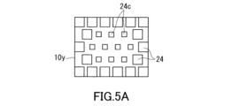
- FIG. 5A is a diagram illustrating a method for forming an introduction port.
- FIG. 5B is a diagram illustrating a method for forming an introduction port.
- FIG. 5A is a diagram illustrating a method for forming an introduction port.
- FIG. 6 is a plan view and a cross-sectional view illustrating another method of forming the introduction port.
- FIG. 7 is a plan view of a gas generation section according to modification example 1.
- FIG. 8A is a cross-sectional view of a metal gas-filled cell using a cell body according to Modification Example 2.
- FIG. 8B is a plan view of a cell main body according to Modification 2.
- FIG. 9 is a plan view of a gas generation section according to modification example 3.
- FIG. 1 is a perspective view of a metal gas-filled cell 100 according to an embodiment of the present invention.
- FIG. 2 is a plan view of the cell body 10 of the metal gas-filled cell 100 shown in FIG.
- the metal gas-filled cell 100 includes a cell body 10, a first glass plate 11, and a second glass plate 12.
- the cell body 10 has a first surface 10p and a second surface 10q.
- the first surface 10p and the second surface 10q are surfaces facing each other.
- the first surface 10p and the second surface 10q may each be the main surface of the cell body 10.
- "Main surface” means the surface with the largest area.
- a first glass plate 11 is bonded to the first surface 10p.
- a second glass plate 12 is bonded to the second surface 10q.
- first glass plate 11 and the second glass plate 12 cover the entire first surface 10p and the second surface 10q, respectively.
- the first surface 10p may include a portion not covered by the first glass plate 11.
- the second surface 10q may include a portion not covered by the second glass plate 12.
- a metal gas and a buffer gas are sealed inside the metal gas filled cell 100 .
- the metal gas typically includes alkali metal gas such as K, Rb, and Cs. When an alkali metal gas is sealed, the metal gas filled cell 100 can function as an atomic oscillator by detecting CPT resonance.
- the buffer gas include inert gases. Examples of the inert gas include H 2 gas, N 2 gas, rare gas, and mixed gases thereof. Buffer gas is not essential, and only metal gas may be enclosed.
- Each of the first glass plate 11 and the second glass plate 12 is a thin glass plate that sufficiently transmits light in a predetermined wavelength band.
- Light in a predetermined wavelength band means light that is irradiated when the metal gas-filled cell 100 is actually used.
- the metal gas is Cs gas
- the light in the predetermined wavelength band is light in the Cs absorption wavelength band (for example, 894.6 nm in the case of the Cs-D1 line).
- “Sufficient transmission” means, for example, that the transmittance of light in a predetermined wavelength band is 90% or more.
- Glass plates that can be anodically bonded to the cell body 10 may be used as the first glass plate 11 and the second glass plate 12. Examples of glasses that can be anodically bonded to silicon include silicate glass, borosilicate glass, aluminosilicate glass, and aluminoborosilicate glass.
- the cell body 10 is made of silicon, for example.
- a plurality of metal gas filled cells 100 can be manufactured from one silicon wafer. Silicon does not easily react with alkali metal gas and buffer gas, so when the cell body 10 is made of silicon, it is possible to maintain a stable internal atmosphere of the metal gas-filled cell 100 and to keep the vapor pressure of the alkali metal gas constant. can be kept. By using a high quality silicon wafer, it is expected that the performance of the metal gas filled cell 100 will be improved.
- the first glass plate 11 and the second glass plate 12 can be bonded to the cell body 10 by anodic bonding without using any other bonding material.
- the material of the cell body 10 is not particularly limited.
- the cell body 10 may be made of metal such as stainless steel, or may be made of glass, as long as it is a material that can be microfabricated.
- the shape of the cell body 10 is also not particularly limited.
- the cell body 10 may have a plate-like shape, a cylindrical shape, or a rectangular parallelepiped shape. When the cell body 10 has a rectangular parallelepiped shape, it means that the polyhedron with the minimum volume surrounding the cell body 10 is a rectangular parallelepiped.
- the method of joining the first glass plate 11 and the second glass plate 12 to the cell body 10 is also not particularly limited.
- At least one of the first glass plate 11 and the second glass plate 12 may be bonded to the cell body 10 using a bonding material such as an adhesive, glass frit, or a metal material.
- the method of joining the cell body 10 and the first glass plate 11 may be different from the method of joining the cell body 10 and the second glass plate 12.
- the cell body 10 has an optical chamber 14 and at least one gas generation section 20.
- the optical chamber 14 may be provided on the first glass plate 11 and/or the second glass plate 12.
- the optical chamber 14 may be a portion provided in at least one selected from the cell body 10, the first glass plate 11, and the second glass plate 12, and communicated with the gas generation section 20.
- the optical chamber 14 is a part filled with metal gas and is a light path for detecting CPT resonance.
- the optical chamber 14 is open to at least one of the first surface 10p and the second surface 10q.
- the optical chamber 14 includes a through hole extending through the cell body 10 from the first surface 10p to the second surface 10q.
- the cross-sectional area of the through hole may be constant or may vary in the thickness direction of the cell body 10.
- the through hole serving as the optical chamber 14 is located at the center of the cell body 10.
- the shape of the optical chamber 14 is not particularly limited.
- the shape of the optical chamber 14 may be circular, elliptical, or polygonal in plan view.
- the position of the optical chamber 14 is also not particularly limited, and the optical chamber may be provided at a position offset from the center of the cell body 10. Examples of methods for forming the optical chamber in the first glass plate 11 include forming a recess in the first glass plate 11 using a method such as ion etching, and forming the first glass plate 11 itself into a dome shape. sell.
- the cell body 10 does not have any through holes other than the through hole serving as the optical chamber 14.
- the second glass plate 12 can be more firmly joined to the second surface 10q of the cell body 10.
- the stability of the performance of the metal gas filled cell 100 is improved.
- the optical chamber 14 may be a hole with a bottom. In this case, the second glass plate 12 can be omitted.
- the gas generation unit 20 is a part that generates a solid raw material of metal gas from a raw material solution of metal gas, and also generates metal gas from the solid raw material.
- the gas generation section 20 has a plurality of grooves 22, a plurality of pillars 24, and an inlet 26.
- the plurality of grooves 22 are provided between the plurality of pillars 24 and open to the first surface 10p.
- the plurality of grooves 22 are bottomed grooves.
- a plurality of grooves 22 extend in a lattice shape in a plan view so that the gas generation section 20 has a plurality of pillars 24. In the example of FIG. 1, a plurality of grooves 22 are formed such that a plurality of pillars 24 are arranged in a staggered pattern.
- the pillar 24 has a rectangular (typically square) shape in plan view.
- the shape of the pillar 24 is not particularly limited.
- the shape of the pillar 24 may be prismatic or cylindrical.
- the length D of one side thereof is, for example, 2 mm or more and 8 mm or less.
- the optical chamber 14 is circular in plan view, its diameter ⁇ is, for example, 1 mm or more and 6 mm or less.
- a microchannel 18 is provided between the optical chamber 14 and the gas generation section 20 to communicate them.
- each of the plurality of grooves opened in the first surface 10p plays the role of the microchannel 18.
- the width of the groove as the microchannel 18 is narrower than the width of the groove 22 in the gas generation section 20, for example.
- Such a structure serves to prevent solid sources or source solutions of metal gases from being introduced into the optical chamber 14.
- the width of the groove as the microchannel 18 is, for example, 1 ⁇ m or more and 30 ⁇ m or less.
- the microchannel 18 may be composed of only one groove.
- FIG. 3A is a cross-sectional view of the cell main body 10 taken along the line IIIA-IIIA shown in FIG. 2, and shows the gas generation section 20 enlarged from the lateral direction.
- FIG. 3B is a cross-sectional view of the cell body 10 taken along line IIIB-IIIB shown in FIG. 2.
- the width of each of the plurality of grooves 22 changes periodically along the thickness direction DR of the cell body 10.
- the thickness direction DR of the cell body 10 is a direction from the first surface 10p to the second surface 10q.
- Each of the plurality of grooves 22 has a portion wider than the opening width W of each of the plurality of grooves 22 on the first surface 10p.
- each of the plurality of grooves 22 includes a plurality of first portions 22a and a plurality of second portions 22b.
- the first portion 22a is a portion where the gap distance between adjacent pillars 24 is long.
- the second portion 22b is a portion where the gap distance between adjacent pillars 24 is short.
- First portions 22a and second portions 22b are provided alternately from the first surface 10p to the second surface 10q.
- the width W2 of the second portion 22b of the groove 22 is, for example, equal to the opening width W of the groove 22 on the first surface 10p.
- three stages of first portions 22a are provided along the thickness direction DR.
- the number of first portions 22a and second portions 22b is not particularly limited.
- the solid raw material When a solid raw material is generated from a metal gas raw material solution, the solid raw material adheres to the fine structure constituting the gas generation section 20 and tends to remain in the gas generation section 20 . Further, the fine structure of the gas generation section 20 makes the chemical reaction by heating solid raw materials such as CsN 3 more efficient. Due to the combined effect of increasing the specific surface area and preventing the solid raw material from scattering during thermal decomposition, alkali metal gas can be efficiently generated through the chemical reaction of the solid raw material even at low temperatures.
- the width W of the groove 22 on the first surface 10p is, for example, 1 ⁇ m or more and 100 ⁇ m or less.
- the width W1 of the first portion 22a of the groove 22 is, for example, 5 ⁇ m or more and 200 ⁇ m or less.
- the width W2 of the second portion 22b of the groove 22 is approximately equal to the width W of the groove 22 on the first surface 10p.
- the width W1 of the first portion 22a and the width W2 of the second portion 22b may gradually become narrower from the first surface 10p toward the second surface 10q.
- the length of one side L of the pillar 24 on the first surface 10p is, for example, 50 ⁇ m or more and 500 ⁇ m or less.
- the inlet 26 is an opening for introducing the metal gas raw material solution into the plurality of grooves 22.
- the inlet 26 is a bottomed opening and communicates with the plurality of grooves 22 .
- the introduction port 26 has at least one of a structure in which at least one pillar 24 selected from the plurality of pillars 24 is partially missing, and a structure in which at least one pillar 24 selected from the plurality of pillars 24 is completely missing. include.
- the inlet 26 includes both of these structures. According to such a configuration, the introduction port 26 is less likely to become a dead space, which is advantageous for downsizing the metal gas-filled cell 100.
- the droplet of the raw material solution is large relative to the width of the groove 22 and it is difficult to directly inject the droplet into the groove 22, the droplet can be injected into the inlet 26. Therefore, it is possible to reduce the possibility that the first surface 10p of the cell body 10 will be contaminated with the raw material solution or solid raw material. When the first surface 10p is kept clean, the first glass plate 11 can be reliably bonded to the first surface 10p. For these reasons, it is possible to reduce the size of the metal gas-filled cell 100 and improve the stability of its performance.
- a structure in which a portion of the pillar 24 is missing can be formed by cutting off a portion of the pillar 24 to provide the introduction port 26.
- the plurality of pillars 24 include a first pillar 24a and a second pillar 24b.
- the first pillar 24a is a pillar that has the largest area among the plurality of pillars 24 when the cell main body 10 is viewed from above.
- the pillar 24 having a square shape in plan view is the first pillar 24a.
- the second pillar 24b is a pillar having a smaller area than the first pillar 24a.
- the second pillar 24b is a pillar adjacent to the introduction port 26. A part of the first pillar 24a is missing to form a second pillar 24b.
- a structure in which the entire pillar 24 is missing can be formed by cutting off the entire pillar 24 to provide the introduction port 26.
- the structure can be formed by ensuring a region in the gas generation section 20 where the pillar 24 does not exist.
- the structure of the second pillar 24b is not particularly limited.
- the second pillar 24b may be a short pillar formed by cutting or breaking the upper surface of the first pillar 24a, or may be a notch pillar formed by cutting the side surface of the first pillar 24a. It may be a thin pillar formed by cutting the peripheral edge of the first pillar 24a, or it may be a deformed pillar having both of these characteristics. These are collectively called missing pillars. Further, when all of the pillars 24 are removed, the portion where the pillars 24 were present is recognized as a relatively wide space existing between the pillar groups in the gas generation section 20. Such a space is called a pillar-deficient region. That is, the gas generation section 20 includes a missing pillar and/or a missing pillar region.
- the inlet 26 may be surrounded by a plurality of pillars 24.
- the raw material solution can be delivered to every corner of the plurality of grooves 22, so that a solid raw material can be efficiently produced from the raw material solution.
- the amount of raw material solution used can be reduced, and the possibility that the first surface 10p of the cell body 10 will be contaminated with the raw material solution or solid raw material can be further reduced.
- the entire introduction port 26 may be contained within the region where the plurality of grooves 22 and the plurality of pillars 24 are provided. According to such a configuration, dead space is less likely to occur.
- the cell body 10 has a rectangular shape in plan view, more specifically a square shape.
- a gas generating section 20 is provided at at least one selected from the four corners of the cell body 10. According to such a configuration, the amount of raw material solution to be introduced into each of the gas generation units 20 is reduced. As a result, the possibility that the first surface 10p of the cell body 10 will be contaminated with the raw material solution or solid raw material can be reduced. Additionally, the four corners inherently tend to become dead spaces. By providing the gas generating section 20 at at least one corner selected from the four corners, the dead space of the cell body 10 can be sufficiently reduced. This is advantageous for downsizing the metal gas filled cell 100.
- a gas generation section 20 is provided at each of the four corners of the cell body 10.
- the above effects are further improved.
- the metal gas-filled cell 100 has a highly symmetrical structure. This is advantageous in suppressing blur in the center of the optical axis, and enables stable mounting of the metal gas-filled cell 100 (for example, mounting in an atomic clock).
- a plurality of (in this embodiment, four) gas generation units 20 are independent from each other.
- Raw materials cannot be directly transferred from the gas generation section 20 to the gas generation section 20.
- the plurality of gas generators 20 communicate only through the microchannel 18 and the optical chamber 14. Even with such a configuration, the amount of raw material solution to be introduced into each of the gas generation units 20 is reduced, so the above-mentioned effects can be obtained.
- the amount of raw material solution used decreases, the cost of the metal gas-filled cell 100 also decreases.
- the amount of solid raw material remaining in the cell body 10 can also be reduced. This is also advantageous from the viewpoint of stability of performance of the metal gas-filled cell 100.
- Note that an embodiment in which a plurality of gas generation units 20 are connected to each other is also possible. When the amount of the raw material solution supplied to the gas generation section 20 is not uniform, the effect of making the amount uniform can be expected.
- the gas generating section 20 may be provided only at two or three corners selected from the four corners of the cell body 10. For example, when a structure other than the metal gas-filled cell 100 is built in one or two specific corners selected from the four corners, the gas generation unit is placed in two or three corners other than the specific corners. 20 can be built in.
- the depth D1 of the inlet 26 may be greater than the depth D2 of the groove 22.
- the introduction port 26 is slightly deeper than the groove 22, it is easier to form the introduction port 26.
- the depth D1 of the introduction port 26 may be equal to the depth D2 of the groove 22.
- the depth D1 of the introduction port 26 may be less than the depth D2 of the groove 22. According to these configurations, the raw material solution introduced into the introduction port 26 can smoothly move to the plurality of grooves 22.
- the shape of the inlet 26 is not particularly limited.
- the shape of the introduction port 26 in plan view may be circular, oval, or polygonal such as a rectangle.
- the inlet 26 may have the shape of a cylinder, an elliptical cylinder, or a polygonal cylinder.
- the opening area of the introduction port 26 is smaller than the opening area of the optical chamber 14.
- Such a structure contributes to miniaturization of the metal gas-filled cell 100.
- the sizes of the optical chamber 14 and the introduction port 26 are not particularly limited.
- the opening area of the inlet 26 is larger than the area of the pillar 24, for example.
- the introduction port 26 has a circular shape in plan view and the pillar 24 has a rectangular shape such as a square in plan view
- the diameter of the introduction port 26 may be larger than the length of one side of the pillar 24. According to such a configuration, it is easy to inject the raw material solution into the groove 22. For the same reason, the diameter of the inlet 26 may be larger than the width W of the groove 22.
- the "diameter of the introduction port 26" means the diameter of a circle having an area equal to the area defined by the outline of the introduction port 26 in a plan view.
- the introduction port 26 and the plurality of grooves 22 are open only to the first surface 10p.
- the gas generation section 20 does not penetrate the second surface 10q. According to such a configuration, the raw material solution can be easily supplied to the groove 22 from the first surface 10p through the inlet 26.
- FIG. 4 is a process diagram showing a method for manufacturing the metal gas-filled cell 100.
- a thin film 30 for a mask is formed on one surface of the substrate 10y.
- the thin film 30 may be a metal thin film such as Cr, Al, or Ni, or may be a silicon oxide film.
- the thin film 30 may be formed by a vapor phase method such as evaporation or sputtering.
- the substrate 10y is, for example, a silicon wafer. Since a plurality of metal gas-filled cells 100 can be manufactured from one substrate 10y, the method of this embodiment is excellent in productivity.
- the silicon wafer serving as the substrate 10y may be a polycrystalline wafer or a single-crystalline wafer.
- the internal atmosphere of the metal gas-filled cell 100 can be kept more stable, and the vapor pressure of the alkali metal gas can be kept more constant. Since a single crystal wafer has no grain boundaries, it is easy to form the fine structure of the gas generation section 20 with high dimensional accuracy. The larger the substrate 10y, the more compact metal gas-filled cells 100 can be mass-produced.
- a resist 32 is applied to the surface of the thin film 30, and the resist 32 is patterned using photolithography.
- the thin film 30 may be omitted and the resist 32 may be formed directly on the substrate 10y.
- step 3 a part of the thin film 30 is removed using an etching solution to expose the surface of the substrate 10y.
- the optical chamber 14 (not shown) and the gas generation section 20 are formed by deep reactive ion etching.
- the optical chamber 14 and the gas generation section 20 are formed at once by deep reactive ion etching. Therefore, it is possible to manufacture the cell body 10 with a small number of steps.
- the gas generation section 20 is formed in step 4.
- Microchannel 18 is also formed in step 4.
- the gas generation section 20 is formed by deep reactive ion etching from one surface (first surface) of the substrate 10y.
- the optical chamber 14 is formed by deep reactive ion etching from the other surface (second surface) of the substrate 10y.
- FIGS. 5A and 5B are diagrams illustrating a method of forming the introduction port 26.
- FIG. 5A is a plan view of the substrate 10y.
- FIG. 5B is a cross-sectional view of the substrate 10y.
- the resist 32 is patterned so that a plurality of thin pillars 24c are located in predetermined regions, and the grooves 22 are formed by deep reactive ion etching.
- the predetermined area is an area where the introduction port 26 is to be formed.
- the number of thin pillars 24c may be one.
- the substrate 10y is largely etched in the horizontal direction at the deepest position of the groove 22. As a result, the thin pillar 24c is removed and the introduction port 26 is formed in a predetermined area.
- FIG. 6 is a plan view and a cross-sectional view illustrating another method of forming the introduction port 26.
- the pattern of the pillars 24 is not drawn in the predetermined area corresponding to the introduction port 26.
- the inlet 26 may be formed by deep reactive ion etching.
- the cell body 10 is obtained by removing the thin film 30 and the resist 32.
- the second glass plate 12 is bonded to the second surface 10q of the cell body 10.
- the method for bonding the second glass plate 12 and the cell body 10 is anodic bonding.
- the second glass plate 12 and the cell body 10 are placed on top of each other, and a DC voltage is applied between them while heating them.
- the heating temperature is, for example, 150°C or higher and 600°C or lower.
- the applied voltage is, for example, 200V or more and 1200V or less. Note that when the optical chamber 14 is a hole with a bottom, the second glass plate 12 is unnecessary and step 5 is omitted.
- step 6 the metal gas raw material solution 34a is injected into the inlet 26, and the raw material solution 34a is introduced into the groove 22.
- the raw material solution 34a is supplied to the groove 22 by capillary action.
- the raw material solution 34a is also injected from the first surface 10p. Injection is performed by a device or device suitable for injecting liquid into a small area. Such instruments or devices include micropipettes, ink jets, and the like. For example, at least one of the groove 22, the pillar 24, and the inlet 26 can be recognized by image processing, and the raw material solution 34a can be automatically injected using these devices or devices. Alternatively, if alignment marks are provided on the silicon wafer on which the cell body 10 is formed, such alignment marks may be used to align the above-mentioned equipment or device.
- step 7 the solvent contained in the raw material solution 34a is evaporated, and a solid raw material 34b of metal gas is deposited on the surface of the pillar 24.
- the solvent is evaporated by heating the cell body 10. Heating of the cell body 10 can be achieved by placing the cell body 10 on a hot plate or treating the cell body 10 in a heating furnace.
- the raw material solution 34a is a solution containing a metal compound.
- the metal compound include metal azides such as CsN 3 and metal halides such as CsCl.
- the metal compound is typically an alkali metal compound.
- an alkali metal gas is generated using a chemical reaction of an alkali metal compound.
- a CsN 3 solution is introduced into the gas generation section 20 of the cell body 10 to precipitate solid CsN 3 .
- the solvent in the CsN3 solution may be an inorganic solvent such as water, or an organic solvent such as alcohol, acetone, or acetonitrile.
- the heating temperature of the cell body 10 when depositing the solid raw material 34b on the surface of the pillar 24 is, for example, 25° C. or more and 315° C. or less.
- Heating temperature is the ambient temperature at which the cell body 10 is placed.
- the heating temperature is the surface temperature of the hot plate.
- the heating temperature is the temperature inside the heating furnace.
- the solid raw material 34b and the cell body 10 may be degassed in a vacuum atmosphere. According to this embodiment, since the gas generation section 20 is open to the first surface 10p, efficient degassing is possible.
- the first glass plate 11 is bonded to the first surface 10p of the cell body 10.
- the method of bonding the first glass plate 11 and the cell body 10 is also anodic bonding.
- the first glass plate 11 and the cell body 10 are placed on top of each other, and a DC voltage is applied between them while heating them.
- the heating temperature is, for example, 150°C or higher and 300°C or lower.
- the applied voltage is, for example, 200V or more and 1200V or less.
- the process in step 8 is performed in a vacuum or in an inert gas atmosphere such as a rare gas or N 2 gas.
- the degree of vacuum is, for example, 1 ⁇ 10 ⁇ 3 Pa or more and 1 ⁇ 10 ⁇ 7 Pa or less.
- the atmosphere for performing step 8 is such that after the first glass plate 11 is joined to the cell body 10, the amount of solid raw material 34b present in the cell body 10 and the amount of buffer gas present in the cell body 10 are controlled. Determined based on assumptions.
- first glass plate 11 By bonding the first glass plate 11 and the cell body 10, not only the first surface 10p of the cell body 10 in the portion other than the gas generation section 20 but also the upper surface of the plurality of pillars 24 of the gas generation section 20 are covered with the first glass. It is joined to the plate 11.
- the dimensions of the first glass plate 11 in plan view may match the dimensions of the first surface 10p of the cell body 10.
- the dimensions of the second glass plate 12 in plan view may match the dimensions of the second surface 10q of the cell body 10.
- a metal gas is generated from the solid raw material 34b, and the metal gas is introduced into the optical chamber 14.
- metal gas is generated from the solid raw material 34b by heating the cell body 10. Heating of the cell body 10 can be achieved by placing the cell body 10 on a hot plate or treating the cell body 10 in a heating furnace. The heating temperature of the cell body 10 when generating the metal gas is, for example, 250° C. or more and 400° C. or less. Note that instead of heating the cell body 10, the solid raw material 34b may be decomposed by UV irradiation to generate metal gas, or the solid raw material 34b may be decomposed by laser light irradiation to generate metal gas. Good too.
- Cs and N 2 are produced according to the following chemical reaction.
- the alkali metal production method by thermal decomposition of metal azide does not generate products that affect performance such as gas pressure inside the metal gas-filled cell 100, and generates alkali metal gas and N 2 gas, which is a buffer gas.
- alkali metal gas and N 2 gas which is a buffer gas.
- the alkali metal compound is not limited to metal azide.
- Cs gas can be generated by reacting CsCl and BaN 6 .
- the metal gas-filled cell 100 of this embodiment is obtained.
- a portion of the solid raw material 34b remains undecomposed in the gas generation section 20. That is, the metal gas-filled cell 100 has the solid raw material 34b of the metal gas attached to the gas generation section 20.
- no member or material other than the solid raw material 34b exists inside the metal gas-filled cell 100. Therefore, the internal atmosphere of the metal gas-filled cell 100 can be kept stable, and the vapor pressure of the alkali metal gas can be kept constant. Since the solid raw material 34b remains in the gas generation unit 20, if the vapor pressure of the metal gas in the optical chamber 14 decreases due to deterioration over time, the metal gas can be compensated for by reheating the metal gas filled cell 100. is also possible.
- the metal gas-filled cell 100 of this embodiment contains a predetermined concentration of metal gas generated inside the optical chamber 14 in an operating environment (for example, about 80° C. in the case of Cs gas). Therefore, the required sizes of the optical chamber 14 and the gas generation section 20 are related to each other. Moreover, the required size also differs depending on the type of metal gas. Furthermore, the strength and durability achieved by bringing the first glass plate 11 and the second glass plate 12 into close contact with the cell body 10 include the adhesive surface between these glass plates 11 and 12 and the cell body 10. Area also matters. Taking these conditions into consideration, the size of the cell body 10 and the size of each part are designed.
- FIG. 7 is a plan view of the gas generation section 20a according to Modification 1.
- the gas generation unit 20a can be applied to the metal gas-filled cell 100 shown in FIGS. 1 and 2.
- the opening area of the inlet 26 is smaller than the area of the pillar 24.
- the introduction port 26 has a circular shape in plan view and the pillar 24 has a rectangular shape such as a square in plan view
- the diameter of the introduction port 26 may be smaller than the length of one side of the pillar 24. According to such a configuration, the first surface 10p is less likely to be contaminated when producing a solid raw material from a raw material solution.
- the plurality of pillars 24 are arranged in a staggered manner.
- the introduction port 26 is formed across a plurality of (for example, two or three) pillars 24 .
- the plurality of grooves 22 have a T-shaped portion. The center of the inlet 26 is located in the T-shaped portion of the groove 22. That is, the introduction port 26 is formed across the three pillars 24.
- FIG. 8A is a cross-sectional view of a metal gas-filled cell 200 using a cell body 10b according to Modification 2.
- FIG. 8B is a plan view of the cell body 10b according to Modification 2.
- FIG. The metal gas filled cell 200 includes a cell body 10b having a step 28.
- the step 28 is provided on the first surface 10p so as to surround the gas generation section 20. According to such a configuration, the first surface 10p around the step 28 is less likely to be contaminated with the raw material solution and the solid raw material. Therefore, the first glass plate 11 can be reliably joined to the first surface 10p of the cell body 10b.
- the groove 22 and the introduction port 26 open at the bottom of the recess created by the step 28.
- the first glass plate 11 is joined to the first surface 10p around the step 28.
- a space with a height corresponding to the step 28 exists between the first glass plate 11 and the gas generation section 20.
- the step 28 may be provided only around the gas generation section 20.
- Optical chamber 14 is not surrounded by step 28 .
- a step 28 exists at 360° around the gas generation section 20, while a line segment connecting the outer edge of the cell body 10b and the optical chamber 14 without intersecting the step 28 is It can exist. According to such a configuration, bonding between the first glass plate 11 and the first surface 10p can be achieved reliably. As a result, the stability of the performance of the metal gas filled cell 200 is improved.
- FIG. 9 is a plan view of the gas generation section 20b according to Modification 3.
- a plurality of pillars 24 are arranged radially.
- the pillar 24 is not provided in the central portion of the gas generation section 20b, but an inlet 26 is provided.
- Each pillar 24 is not rectangular in plan view and has different sizes.
- the structure in each direction when viewed from the inlet 26 is isotropic. Thereby, the solid raw material can be uniformly supplied to each pillar 24.
- the plurality of pillars 24 may be arranged in a spiral shape.
- a helical arrangement is an arrangement obtained by twisting a radial arrangement.
- since the introduction port 26 is present in the center of the radial arrangement, it is easy to identify the position where the solution is introduced.
- a plurality of pillars 24 are arranged symmetrically over 360 degrees around the inlet 26.
- the plurality of pillars 24 may be arranged only within a 180 degree range around the introduction port 26.
- a plurality of structures having a plurality of pillars 24 arranged in a range of 60 degrees may be provided around the introduction port 26.
- the pillars 24 can be appropriately arranged depending on the purpose. Of course, these arrangements may be used in combination with other arrangements.
- the size of the pillars, the arrangement of the pillars, the arrangement of the introduction ports, and the size of the introduction ports are not limited to those shown in the embodiments and modified examples.
- large pillars may be arranged only around the inlet in plan view for the purpose of preventing the raw material solution from accidentally flowing out or scattering when the solvent evaporates.
- the introduction port 26 may be a bottomed hole that opens only on the second surface 10q.
- the optical chamber may be constituted by a first glass plate provided with a recessed portion at a predetermined position and a cell body.
- the optical chamber may be configured only by the recessed portion of the first glass plate.
- an optical chamber may be provided in the second glass plate on the second surface side, which is the opposite side to the first surface side where the gas generation section opens.
- the gas generation section and the optical chamber are connected by a microchannel (communication hole) that passes through the cell body. In this way, a design suitable for the usage of the metal gas-filled cell can be selected.
- the recessed portion of the glass plate may be formed by a method such as etching.
- the metal gas-filled cell of the present invention is useful for atomic clocks, magnetic sensors, inertial sensors, and the like.
Landscapes
- Physics & Mathematics (AREA)
- Engineering & Computer Science (AREA)
- General Physics & Mathematics (AREA)
- Chemical & Material Sciences (AREA)
- Manufacturing & Machinery (AREA)
- Life Sciences & Earth Sciences (AREA)
- Ecology (AREA)
- Condensed Matter Physics & Semiconductors (AREA)
- Dispersion Chemistry (AREA)
- Analytical Chemistry (AREA)
- Microelectronics & Electronic Packaging (AREA)
- Optical Measuring Cells (AREA)
- Stabilization Of Oscillater, Synchronisation, Frequency Synthesizers (AREA)
- Physical Or Chemical Processes And Apparatus (AREA)
Priority Applications (4)
| Application Number | Priority Date | Filing Date | Title |
|---|---|---|---|
| JP2024545616A JPWO2024053527A1 (https=) | 2022-09-09 | 2023-08-30 | |
| US19/109,995 US20260079451A1 (en) | 2022-09-09 | 2023-08-30 | Metal-gas-filled cell |
| EP23863065.1A EP4586419A1 (en) | 2022-09-09 | 2023-08-30 | Metal gas sealed cell |
| CN202380058027.3A CN119585961A (zh) | 2022-09-09 | 2023-08-30 | 金属气体封入单元 |
Applications Claiming Priority (2)
| Application Number | Priority Date | Filing Date | Title |
|---|---|---|---|
| JP2022-143731 | 2022-09-09 | ||
| JP2022143731 | 2022-09-09 |
Publications (1)
| Publication Number | Publication Date |
|---|---|
| WO2024053527A1 true WO2024053527A1 (ja) | 2024-03-14 |
Family
ID=90190992
Family Applications (1)
| Application Number | Title | Priority Date | Filing Date |
|---|---|---|---|
| PCT/JP2023/031643 Ceased WO2024053527A1 (ja) | 2022-09-09 | 2023-08-30 | 金属ガス封入セル |
Country Status (5)
| Country | Link |
|---|---|
| US (1) | US20260079451A1 (https=) |
| EP (1) | EP4586419A1 (https=) |
| JP (1) | JPWO2024053527A1 (https=) |
| CN (1) | CN119585961A (https=) |
| WO (1) | WO2024053527A1 (https=) |
Citations (3)
| Publication number | Priority date | Publication date | Assignee | Title |
|---|---|---|---|---|
| JP2013038382A (ja) | 2011-07-13 | 2013-02-21 | Ricoh Co Ltd | 原子発振器及び原子発振器の製造方法 |
| JP2022020207A (ja) * | 2020-07-20 | 2022-02-01 | 日本電気硝子株式会社 | 原子セル及びその製造方法 |
| WO2022097557A1 (ja) | 2020-11-06 | 2022-05-12 | 国立大学法人京都大学 | 金属ガス封入セル及びその製造方法 |
-
2023
- 2023-08-30 JP JP2024545616A patent/JPWO2024053527A1/ja active Pending
- 2023-08-30 US US19/109,995 patent/US20260079451A1/en active Pending
- 2023-08-30 EP EP23863065.1A patent/EP4586419A1/en active Pending
- 2023-08-30 WO PCT/JP2023/031643 patent/WO2024053527A1/ja not_active Ceased
- 2023-08-30 CN CN202380058027.3A patent/CN119585961A/zh active Pending
Patent Citations (3)
| Publication number | Priority date | Publication date | Assignee | Title |
|---|---|---|---|---|
| JP2013038382A (ja) | 2011-07-13 | 2013-02-21 | Ricoh Co Ltd | 原子発振器及び原子発振器の製造方法 |
| JP2022020207A (ja) * | 2020-07-20 | 2022-02-01 | 日本電気硝子株式会社 | 原子セル及びその製造方法 |
| WO2022097557A1 (ja) | 2020-11-06 | 2022-05-12 | 国立大学法人京都大学 | 金属ガス封入セル及びその製造方法 |
Also Published As
| Publication number | Publication date |
|---|---|
| US20260079451A1 (en) | 2026-03-19 |
| CN119585961A (zh) | 2025-03-07 |
| EP4586419A1 (en) | 2025-07-16 |
| JPWO2024053527A1 (https=) | 2024-03-14 |
Similar Documents
| Publication | Publication Date | Title |
|---|---|---|
| CN102970035B (zh) | 原子振荡器和用于制造原子振荡器的方法 | |
| US7400207B2 (en) | Anodically bonded cell, method for making same and systems incorporating same | |
| US8906470B2 (en) | Method for producing a microfabricated atomic vapor cell | |
| JP5961998B2 (ja) | 原子発振器の製造方法 | |
| US9201404B2 (en) | Alkali metal cell, atomic oscillator, and alkali metal cell fabricating method | |
| US20180188030A1 (en) | Micro three-dimensional shell resonator gyroscope | |
| US20110187464A1 (en) | Apparatus and methods for alkali vapor cells | |
| US20050007118A1 (en) | Micromachined alkali-atom vapor cells and method of fabrication | |
| US20120298295A1 (en) | Fabrication techniques to enhance pressure uniformity in anodically bonded vapor cells | |
| TW201126902A (en) | Piezoelectric vibrating devices and methods for manufacturing same | |
| US20180212613A1 (en) | Atom cell, method of manufacturing atom cell, quantum interference device, atomic oscillator, electronic apparatus, and moving object | |
| Overstolz et al. | Wafer scale fabrication of highly integrated rubidium vapor cells | |
| JP7780803B2 (ja) | 金属ガス封入セル及びその製造方法 | |
| WO2024053527A1 (ja) | 金属ガス封入セル | |
| CN103955129A (zh) | 具有双反射镜的微型原子气体腔器件及其制造方法 | |
| JP6179277B2 (ja) | アルカリ金属セルの製造方法及び原子発振器の製造方法 | |
| US7508132B2 (en) | Device having a getter structure and a photomask | |
| JPS5947287B2 (ja) | ツイストネマテイツク液晶表示素子の製造方法 | |
| JP6036230B2 (ja) | アルカリ金属セルの製造方法及び原子発振器の製造方法 | |
| Gorecki | Development of first European chip-scale atomic clocks: Technologies, assembling and metrology | |
| US12602016B2 (en) | Chip-scale atomic beam generating systems | |
| Liew et al. | Micromachined alkali atom vapor cells for chip-scale atomic clocks | |
| WO2022018951A1 (ja) | 原子セル及びその製造方法 | |
| RU2819863C1 (ru) | Способ изготовления малогабаритной атомной ячейки с парами щелочного металла | |
| JPH08203875A (ja) | ドライエッチングによる部品の製造方法 |
Legal Events
| Date | Code | Title | Description |
|---|---|---|---|
| 121 | Ep: the epo has been informed by wipo that ep was designated in this application |
Ref document number: 23863065 Country of ref document: EP Kind code of ref document: A1 |
|
| WWE | Wipo information: entry into national phase |
Ref document number: 202380058027.3 Country of ref document: CN |
|
| WWE | Wipo information: entry into national phase |
Ref document number: 2024545616 Country of ref document: JP |
|
| WWP | Wipo information: published in national office |
Ref document number: 202380058027.3 Country of ref document: CN |
|
| WWE | Wipo information: entry into national phase |
Ref document number: 2023863065 Country of ref document: EP |
|
| NENP | Non-entry into the national phase |
Ref country code: DE |
|
| ENP | Entry into the national phase |
Ref document number: 2023863065 Country of ref document: EP Effective date: 20250409 |
|
| WWP | Wipo information: published in national office |
Ref document number: 2023863065 Country of ref document: EP |