WO2024053505A1 - Unité de borne, borne femelle et borne mâle - Google Patents
Unité de borne, borne femelle et borne mâle Download PDFInfo
- Publication number
- WO2024053505A1 WO2024053505A1 PCT/JP2023/031431 JP2023031431W WO2024053505A1 WO 2024053505 A1 WO2024053505 A1 WO 2024053505A1 JP 2023031431 W JP2023031431 W JP 2023031431W WO 2024053505 A1 WO2024053505 A1 WO 2024053505A1
- Authority
- WO
- WIPO (PCT)
- Prior art keywords
- male terminal
- contact
- terminal
- pair
- press
- Prior art date
Links
- 229910052751 metal Inorganic materials 0.000 claims abstract description 93
- 239000002184 metal Substances 0.000 claims abstract description 93
- 238000003466 welding Methods 0.000 claims description 36
- 238000005452 bending Methods 0.000 claims description 23
- 238000006073 displacement reaction Methods 0.000 abstract description 19
- 210000002105 tongue Anatomy 0.000 description 99
- 238000003825 pressing Methods 0.000 description 19
- 238000003780 insertion Methods 0.000 description 7
- 230000037431 insertion Effects 0.000 description 7
- 238000000034 method Methods 0.000 description 7
- 230000008569 process Effects 0.000 description 6
- 230000007704 transition Effects 0.000 description 6
- 238000013459 approach Methods 0.000 description 5
- 230000000694 effects Effects 0.000 description 5
- 238000000926 separation method Methods 0.000 description 4
- RYGMFSIKBFXOCR-UHFFFAOYSA-N Copper Chemical compound [Cu] RYGMFSIKBFXOCR-UHFFFAOYSA-N 0.000 description 3
- 229910000881 Cu alloy Inorganic materials 0.000 description 3
- 229910052802 copper Inorganic materials 0.000 description 3
- 239000010949 copper Substances 0.000 description 3
- 238000005520 cutting process Methods 0.000 description 3
- 230000005489 elastic deformation Effects 0.000 description 3
- 239000000463 material Substances 0.000 description 3
- 208000000884 Airway Obstruction Diseases 0.000 description 2
- 229910000838 Al alloy Inorganic materials 0.000 description 2
- 206010008589 Choking Diseases 0.000 description 2
- 229910052782 aluminium Inorganic materials 0.000 description 2
- XAGFODPZIPBFFR-UHFFFAOYSA-N aluminium Chemical compound [Al] XAGFODPZIPBFFR-UHFFFAOYSA-N 0.000 description 2
- 238000006243 chemical reaction Methods 0.000 description 2
- 238000012986 modification Methods 0.000 description 2
- 230000004048 modification Effects 0.000 description 2
- 238000004080 punching Methods 0.000 description 2
- 230000009467 reduction Effects 0.000 description 2
- 229910001369 Brass Inorganic materials 0.000 description 1
- 230000015572 biosynthetic process Effects 0.000 description 1
- 239000010951 brass Substances 0.000 description 1
- 230000008859 change Effects 0.000 description 1
- 238000002788 crimping Methods 0.000 description 1
- 230000007423 decrease Effects 0.000 description 1
- 238000010586 diagram Methods 0.000 description 1
- 239000007769 metal material Substances 0.000 description 1
- 230000000149 penetrating effect Effects 0.000 description 1
Images


Classifications
-
- H—ELECTRICITY
- H01—ELECTRIC ELEMENTS
- H01R—ELECTRICALLY-CONDUCTIVE CONNECTIONS; STRUCTURAL ASSOCIATIONS OF A PLURALITY OF MUTUALLY-INSULATED ELECTRICAL CONNECTING ELEMENTS; COUPLING DEVICES; CURRENT COLLECTORS
- H01R13/00—Details of coupling devices of the kinds covered by groups H01R12/70 or H01R24/00 - H01R33/00
- H01R13/02—Contact members
- H01R13/04—Pins or blades for co-operation with sockets
-
- H—ELECTRICITY
- H01—ELECTRIC ELEMENTS
- H01R—ELECTRICALLY-CONDUCTIVE CONNECTIONS; STRUCTURAL ASSOCIATIONS OF A PLURALITY OF MUTUALLY-INSULATED ELECTRICAL CONNECTING ELEMENTS; COUPLING DEVICES; CURRENT COLLECTORS
- H01R13/00—Details of coupling devices of the kinds covered by groups H01R12/70 or H01R24/00 - H01R33/00
- H01R13/02—Contact members
- H01R13/15—Pins, blades or sockets having separate spring member for producing or increasing contact pressure
- H01R13/187—Pins, blades or sockets having separate spring member for producing or increasing contact pressure with spring member in the socket
Definitions
- the present disclosure relates to a terminal unit and a female terminal and a male terminal used in the terminal unit.
- Patent Document 1 discloses a terminal unit consisting of a plate-shaped male terminal expressed as a tab-shape, and a female terminal connected to the male terminal.
- the female terminal has a pair of walls facing each other across a male terminal insertion gap, one wall is provided with an elastic contact piece for pressing the male terminal against the other wall, and the other wall is provided with an elastic contact piece for pressing the male terminal against the other wall. has a plurality of protruding contacts.
- the terminal unit of Patent Document 1 has a structure in which the flat male terminal is sandwiched between a pair of wall portions of the female terminal, so the gripping force against external force in the plate width direction of the male terminal is small. Therefore, it is conceivable that slight sliding friction occurs between the male and female terminals due to vibrations, etc., and the contact resistance value increases. Therefore, further improvements in the terminal unit have been required.
- a terminal unit that can suppress the displacement of the male terminal with respect to the female terminal in the board width direction and suppress an increase in contact resistance due to slight sliding friction between the male and female terminals, and a female terminal and a male terminal used in the terminal unit. Disclose.
- the terminal unit of the present disclosure includes a male terminal having a plate shape and a female terminal connected to the male terminal, and the female terminal is provided with a male terminal press-fitting gap in which the male terminal is press-fitted and arranged.
- the male terminal has a first contact portion and a second contact portion that are arranged to face each other, and the male terminal has a first contact portion and a second contact portion that are arranged opposite to each other.
- the first contact portion of the female terminal has a pair of inclined portions inclined toward one side, and the first contact portion of the female terminal is opposed to the one side surface in the plate thickness direction of the male terminal, and the pair of inclined portions of the male terminal are the second contact portion of the female terminal faces the other surface of the male terminal in the plate thickness direction; has a pair of second inclined side edges that are inclined respectively along the pair of inclined parts of the screen, and at least one of the pair of first inclined side edges and the pair of second inclined side edges includes the A contact forming metal fitting formed of a separate thin metal plate that is thinner than the first sloped side edge and the second sloped side edge and easily deformable is fixed in a conductive manner, and the contact forming metal fitting is a pair of first contact portions protruding toward the male terminal press-fitting gap; the male terminal is allowed to be press-fitted into the male terminal press-fitting gap by bending deformation of the pair of first contact portions; With the male terminal press-fitted into the male terminal press-fitting gap, the elastic restoring force
- the female terminal of the present disclosure is a female terminal used in the terminal unit of the present disclosure.
- the male terminal of the present disclosure is a male terminal used in the terminal unit of the present disclosure.
- a terminal unit capable of suppressing displacement of a male terminal with respect to a female terminal in the board width direction and an increase in contact resistance value due to slight sliding friction between the female and male terminals, and a female terminal unit used in the terminal unit are provided.
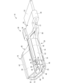
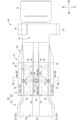
- FIG. 1 is a perspective view showing a terminal unit according to Embodiment 1 in a state where a male terminal and a female terminal are fitted together.
- FIG. 2 is a plan view of the terminal unit shown in FIG. 1.
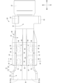
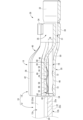
- FIG. 3 is a longitudinal sectional view of the terminal unit shown in FIG. 1, and is a sectional view taken along line III--III in FIG.
- FIG. 4 is an enlarged cross-sectional view of the IV-IV cross section in FIG.
- FIG. 5 is a sectional view taken along line VV in FIG.
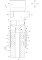
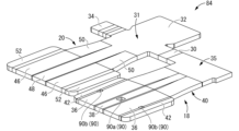
- FIG. 6 is a perspective view showing the female terminal constituting the terminal unit shown in FIG. 1 in an unfitted state with the male terminal.
- FIG. 7 is a diagram showing a vertical cross-sectional view of the female terminal shown in FIG.
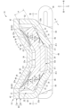
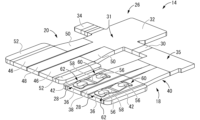
- FIG. 8 is a perspective view showing the female terminal shown in FIG. 6 in an unfolded state before bending.
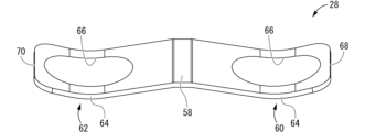
- FIG. 9 is a perspective view showing a contact forming metal fitting constituting the female terminal shown in FIG. 6.
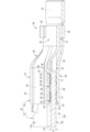
- FIG. 10 is a perspective view showing the terminal unit according to Embodiment 2 in a state where a male terminal and a female terminal are fitted together.
- FIG. 11 is a plan view of the terminal unit shown in FIG. 10.
- FIG. 12 is a sectional view taken along line XII-XII in FIG.
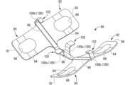
- FIG. 13 is a perspective view showing the female terminal main body constituting the female terminal shown in FIG. 10 in an unfolded state before bending.
- FIG. 14 is a perspective view showing a contact forming metal fitting constituting the female terminal shown in FIG. 10.
- the terminal unit of the present disclosure includes: (1) A male terminal having a plate shape and a female terminal connected to the male terminal, the female terminals being arranged opposite to each other across a male terminal press-fitting gap into which the male terminal is press-fitted.
- the male terminal has a first contact portion and a second contact portion that are inclined toward one side in the thickness direction of the male terminal on both sides of the plate width direction that intersects with the press-fitting direction into the male terminal press-fitting gap.
- the first contact portion of the female terminal faces the one surface of the male terminal in the plate thickness direction, and the first contact portion of the female terminal is arranged along the pair of inclined portions of the male terminal.
- the second contact portion of the female terminal has a pair of first inclined side edges that are inclined respectively, and the second contact portion of the female terminal faces the other surface of the male terminal in the plate thickness direction.
- a pair of second inclined side edges are respectively inclined along the inclined part, and at least one of the pair of first inclined side edges and the pair of second inclined side edges has the first inclined side edge.
- a contact forming metal fitting formed of a separate thin metal plate that is thinner than the edge and the second inclined side edge and easily deformable is fixed in a conductive manner, and the contact forming metal fitting is connected to the male terminal press-fit.
- the male terminal has a pair of first contact portions protruding toward the gap, and the male terminal is allowed to be press-fitted into the male terminal press-fitting gap by bending deformation of the pair of first contact portions, and the male terminal press-fitting gap is With the male terminal press-fitted into the male terminal, the elastic restoring force of the pair of first contact portions of the female terminal brings the pair of first contact portions into pressure contact with the pair of inclined portions of the male terminal, respectively; and the pair of sloped portions of the male terminal are held between the pair of first sloped side edges and the pair of second sloped side edges of the female terminal, respectively.
- the female terminal has a first contact portion and a second contact portion that are arranged opposite to each other across a male terminal press-fitting gap, and a male terminal is connected between the first contact portion and the second contact portion. It has a structure that holds the male terminal press-fitted into the terminal press-fitting gap.
- the male terminal has a pair of inclined parts that are inclined toward one side in the thickness direction of the male terminal on both sides of the male terminal in the board width direction, which is a direction that intersects with the direction of press-fitting into the male terminal press-fitting gap. ing.
- the first contact portion of the female terminal has a pair of first inclined side edges that face one side of the male terminal in the thickness direction and are respectively inclined along the pair of inclined portions of the male terminal.
- the second contact portion of the female terminal has a pair of second inclined side edges that face the other surface of the male terminal in the plate thickness direction and are respectively inclined along the pair of inclined portions of the male terminal.
- at least one of the pair of first sloped side edges and the pair of second sloped side edges is provided with a separate body that is thinner and easily deformable than the first sloped side edges and the second sloped side edge.
- a contact forming fitting formed of a thin metal plate is fixed.
- the contact forming metal fitting has a pair of first contact portions that protrude toward the male terminal press-fitting gap.
- the bending deformation of the pair of first contact portions allows the male terminal to be press-fitted into the male terminal press-fitting gap, while the male terminal is press-fitted into the male terminal press-fitting gap, and the pair of first contact portions of the female terminal Due to the elastic restoring force of the contact portions, the pair of first contact portions are brought into pressure contact with the pair of sloped portions of the male terminal, and the pair of sloped portions of the male terminal are brought into contact with the pair of first sloped side edges of the female terminal. can be respectively sandwiched between the second slanted side edges of the two sides.
- At least one of the pair of first sloped side edges and the pair of second sloped side edges is made of a separate piece of metal that is thinner and easily deformable than the first sloped side edges and the second sloped side edge. Since the pair of first contact portions formed by a thin plate are provided, the male terminal can be easily press-fitted into the male terminal press-fitting gap due to the bending deformation of the pair of first contact portions, reducing the insertion force. can be achieved. Moreover, due to the elastic restoring force of the pair of first contact portions, the pair of sloped portions of the male terminal press-fitted into the male terminal press-fitting gap can be moved between the pair of first sloped side edges and the pair of second sloped side edges of the female terminal.
- the pair of first contact portions are formed using a contact forming fitting formed of a separate thin metal plate that is thinner than the first inclined side edge and the second inclined side edge of the female terminal and is easily flexibly deformed. Because of this structure, compared to the case where the first contact is provided directly on the first inclined side edge and the second inclined side edge, the contact area of the first contact portion to the male terminal is increased, and the contact area of the male terminal is increased.
- first contact part can be provided with a separate contact forming metal fitting, the degree of freedom in designing the first contact part can be improved, and multiple contacts can be arranged in the optimal location and shape according to the usage conditions. It can also be easily installed in
- first inclined side edges and the pair of second inclined side edges “inclining respectively along the pair of inclined parts of the male terminal” means that the pair of first inclined side edges and the pair of second inclined side edges It is sufficient that the first inclined side edge and the second inclined side edge are inclined, and the inclined portion of the male terminal and the first/second inclined side edge do not necessarily have to be parallel.
- the angle of inclination of the first/second inclined side edges may be different from the angle of inclination of the inclined part of the male terminal within a range of about 0 to 10 degrees.
- each first contact portion may be provided on either one of the pair of first inclined side edges and the pair of second inclined side edges, or may be provided on both.
- the shape of each first contact portion is such that when pressed by the male terminal that is press-fitted into the male terminal press-fitting gap, it bends and deforms toward the outside of the male terminal press-fitting gap, and elastically returns toward the inside of the male terminal press-fitting gap. Any shape can be adopted as long as it does.
- the female terminal has a connecting plate portion that electrically connects the first contact portion and the second contact portion, and the second contact portion has an external connection portion.
- the contact forming fittings are fixed to the pair of first inclined side edges of the first contact portion of the female terminal, and the contact forming fittings are fixed to the pair of second inclined side edges of the second contact portion of the female terminal.
- a pair of second contact portions are provided in the portion, each of the second inclined side edges partially protruding toward the male terminal press-fitting gap, and the male terminal is inserted into the male terminal press-fitting gap.
- the pair of sloped portions of the male terminal are pressed against the pair of second contact portions of the female terminal due to the elastic restoring force of the first contact portion when the male terminal is press-fitted. preferable.
- the second contact part of the female terminal is provided with an external connection part to which an external wire terminal or circuit terminal is connected, and a second contact part is formed by partially protruding a part of the same second contact part. is provided at the second contact portion.
- the pair of inclined parts of the male terminal can be brought into pressure contact with the second contact part by the elastic restoring force of the first contact part, and with a small number of parts, the contact pressure between the male and female terminals can be ensured, and the contact pressure between the male and female terminals can be secured. It is possible to simultaneously achieve a reduction in contact resistance.
- the contact forming metal fitting is fixed to at least one of the pair of first inclined side edges and the pair of second inclined side edges by welding.
- it has a welded fixing part.
- a contact forming metal fitting is fixed to each first inclined side edge and/or each second inclined side edge by welding at a welding fixing portion.
- the contact forming metal fitting of the female terminal has a band shape extending in the press-fitting direction of the male terminal into the male terminal press-fitting gap, and the contact forming fitting has a longitudinal direction.
- the welding fixing part is provided at the center of the welding part, and the front protruding tongue piece and the rear protruding tongue piece are provided in a cantilever shape from the welding fixing part toward both ends in the longitudinal direction.
- the protruding tongue piece and the rear protruding tongue piece extend in the longitudinal direction in a curved shape convex toward the male terminal press-fitting gap when viewed from the side, and each of the front protruding tongue piece and the rear protruding tongue piece It is preferable that the first contact portion is provided at an intermediate portion in the longitudinal direction.
- the contact forming metal fitting extends in the shape of a band in the direction in which the male terminal is press-fitted, and a welding fixing part is provided at the central portion in the longitudinal direction.
- a forward protruding tongue piece and a rear protruding tongue piece can be made to protrude in a cantilever shape from the welding fixing part toward both sides in the longitudinal direction (the direction in which the male terminal is press-fitted), and the first contact portions are respectively provided thereon. It is being Therefore, the ability of the first contact portion to follow the displacement of the male terminal in the front-rear direction (press-fitting direction) can be advantageously improved.
- the front protruding tongue piece and the rear protruding tongue piece extend in the longitudinal direction in a curved shape that is convex toward the male terminal press-fitting gap when viewed from the side, and the front protruding tongue piece and the rear protruding tongue piece extend in the longitudinal direction.
- a first contact portion is provided at an intermediate portion of the contact portion.
- the amount of protrusion of the protruding end of the rear protruding tongue into the male terminal press-fitting gap is smaller than that of the first contact part, so that when the male terminal is inserted, the male terminal It can also perform the function of guiding the male terminal toward the press-fit gap while reducing the risk of choking.
- the contact forming metal fitting is configured to provide at least one of the pair of first inclined side edges and the pair of second inclined side edges, Preferably, it has a caulking fixing part that is fixed by caulking.
- a contact forming metal fitting is fixed to each first inclined side edge and/or each second inclined side edge by caulking at a caulking fixing portion. Thereby, the first contact portion of the contact forming metal fitting can be easily fixed while ensuring conductivity to each first inclined side edge and/or each second inclined side edge.
- the contact forming fitting of the female terminal has a band shape extending in the direction of press-fitting the male terminal into the male terminal press-fitting gap, and the contact forming fitting has a longitudinal direction.
- the caulking fixing part is provided at the center of the caulking fixing part, and the front protruding tongue piece and the rear protruding tongue piece are provided in a cantilever shape from the caulking fixing part toward both ends in the longitudinal direction.
- the protruding tongue piece and the rear protruding tongue piece extend in the longitudinal direction in a curved shape convex toward the male terminal press-fitting gap when viewed from the side, and each of the front protruding tongue piece and the rear protruding tongue piece It is preferable that the first contact portion is provided at an intermediate portion in the longitudinal direction.
- the contact forming metal fitting extends in the shape of a band in the direction in which the male terminal is press-fitted, and a caulking fixing part is provided at the center portion in the longitudinal direction.
- a forward protruding tongue piece and a rear protruding tongue piece can be made to protrude in a cantilever shape from the caulking fixing part toward both sides in the longitudinal direction (the direction in which the male terminal is press-fitted), and a first contact part is provided there respectively. It is being Therefore, the ability of the first contact portion to follow the displacement of the male terminal in the front-rear direction (press-fitting direction) can be advantageously improved.
- the front protruding tongue piece and the rear protruding tongue piece extend in the longitudinal direction in a curved shape that is convex toward the male terminal press-fitting gap when viewed from the side, and the front protruding tongue piece and the rear protruding tongue piece extend in the longitudinal direction.
- a first contact portion is provided at an intermediate portion of the contact portion.
- the amount of protrusion of the protruding end of the rear protruding tongue into the male terminal press-fitting gap is smaller than that of the first contact part, so that when the male terminal is inserted, the male terminal It can also perform the function of guiding the male terminal toward the press-fit gap while reducing the risk of choking.
- the male terminal has a central flat portion disposed between the pair of sloped portions in the plate width direction
- the female terminal The first contact portion has a first flat portion that is disposed between the pair of first inclined side edges in the board width direction and extends along and opposite to the central flat portion of the male terminal.
- the second contact portion of the female terminal is arranged between the pair of second inclined side edges in the plate width direction, and has a second contact portion extending along opposite to the central flat portion of the male terminal.
- it has a flat portion.
- the male terminal has a central flat part and a pair of sloped parts on both sides of the central flat part that are inclined to the same side in the thickness direction, and the first contact part and the second contact part of the female terminal are arranged on both sides of the male terminal in the thickness direction. and has a shape similar to the male terminal. That is, the first contact portion includes a first flat portion that extends along the central flat portion of the male terminal, and a first slope side that is arranged on both sides of the first flat portion and slopes along the pair of sloped portions of the male terminal.
- the second contact portion has a second flat portion extending along the central flat portion of the male terminal, and a second flat portion extending along a pair of inclined portions disposed on both sides of the second flat portion.
- the female terminal of the present disclosure includes: (8) Used in the terminal unit according to any one of (1) to (7) above.
- any of the effects (1) to (7) above can be achieved by connecting the male terminal to form a terminal unit.
- the male terminal of the present disclosure includes: (9) Used in the terminal unit according to any one of (1) to (7) above.
- any of the effects (1) to (7) above can be achieved by connecting to the female terminal to form a terminal unit.
- the terminal unit 10 includes a plate-shaped male terminal 12 and a female terminal 14 connected to the male terminal 12.
- the female terminal 14 has a first contact portion 18 and a second contact portion 20 that are arranged to face each other across a male terminal press-fit gap 16 into which the male terminal 12 is press-fitted. Then, the male terminal 12 is press-fitted into the male terminal press-fit gap 16 in the female terminal 14 and comes into contact with the first contact portion 18 and the second contact portion 20, so that the male terminal 12 and the female terminal 14 are electrically connected. It is designed to be connected to.
- terminal unit 10 can be arranged in any direction; however, in the following, upper means the upper side in FIG. 4, lower means the lower side in FIG. 4, and left means the upper side and the right side in FIG.
- the direction will be described as the lower side in FIG. 2, the front as the right side in FIG. 2, and the rear as the left side in FIG.
- a plurality of identical members only some of the members may be labeled with numerals, and the numerals may be omitted for other members.
- the male terminal 12 has a plate shape as a whole, and is constructed using a flat metal fitting (not shown).
- the flat metal fitting has a generally rectangular shape as a whole, has a predetermined plate width and thickness, and extends straight.
- the male terminal 12 is press-fitted into the male terminal press-fitting gap 16 in the female terminal 14 from the rear toward the front, and the part of the male terminal 12 that is press-fitted into the male terminal press-fitting gap 16 (the front part ) has a tapered shape compared to the rear part (see Figures 1, 2, etc.).
- the male terminal 12 is electrically conductive and is made of a metal with low electrical resistance, such as copper, copper alloy, aluminum, or aluminum alloy.
- a pair of inclined portions 22 are formed at both end portions in the plate width direction of the male terminal 12.
- 22 are provided. That is, in the male terminal 12, a pair of inclined portions are provided on both sides in the board width direction, which is a direction that intersects with the direction of press-fitting into the male terminal press-fitting gap 16 (direction from the back to the front), which is a direction orthogonal to the direction in the first embodiment. 22, 22 are provided.
- a central flat part 24 that spreads flat is provided at the center portion of the male terminal 12 in the board width direction located between the pair of inclined parts 22 , 22 .
- the pair of inclined portions 22, 22 may be provided over the entire length of the male terminal 12 in the longitudinal direction, or may be provided over the entire length of the male terminal 12 in the male terminal press-fitting gap 16 (the tapered front portion). ) may be provided only.
- the plate thickness of the male terminal 12 is approximately constant, and the thickness of the pair of inclined parts 22, 22 and the central flat part 24 are each A (see FIGS. 4 and 5). The thickness dimensions of the sloped portions 22, 22 and the central flat portion 24 may be different from each other.
- the angle of inclination of the pair of inclined parts 22, 22 with respect to the central flat part 24 is ⁇ 1 (see FIG. 4).
- the angles of inclination with respect to the flat portion 24 are the same magnitude ( ⁇ 1), but the angles of inclination on both the left and right sides may be different from each other.
- the inclination angle ⁇ 1 of the pair of inclined parts 22, 22 with respect to the central flat part 24 is not limited, but is preferably, for example, 5° or more and 45° or less, more preferably 10° or more and 30°. The following shall apply.
- the inclination angle ⁇ 1 of the inclined portion 22 By setting the inclination angle ⁇ 1 of the inclined portion 22 to 5° or more, the displacement of the male terminal 12 outward in the board width direction is suppressed even when external force is input to the male terminal 12 in the board width direction outward. can do.
- the inclination angle ⁇ 1 of the inclination portion 22 By setting the inclination angle ⁇ 1 of the inclination portion 22 to 45° or less, the vertical dimension of the male terminal 12 and, by extension, the terminal unit 10 can be kept small.
- the rear side of the tapered front portion extends straight, and even if a pair of inclined portions 22, 22 are provided and the male terminal 12 extends rearward as shown in FIG.
- the pair of inclined portions 22, 22 may not be provided, and may have a substantially flat plate shape and extend toward the rear side.
- the rear portion of the male terminal 12 has an electric wire fixed thereto by, for example, crimping or welding, or has a bolt insertion hole so that it can be fixed to a terminal portion of a device.
- the female terminal 14 includes a female terminal body 26 made of a single metal flat plate, and a pair of contact forming fittings 28, 28 fixed to the female terminal body 26.
- the female terminal 14 is formed by bending the female terminal main body 26 to which each contact forming metal fitting 28 is fixed into a predetermined shape described below. That is, the female terminal main body 26 has the first contact portion 18 and the second contact portion 20 that constitute the male terminal press-fitting gap 16, and further allows electrical conduction between the first contact portion 18 and the second contact portion 20. It has a connecting plate part 30 that is connected to.
- the female terminal main body 26 has an external connection portion 32 to which a core wire of an electric wire (not shown) is fixed, or a bus bar or the like constituting an internal circuit of a device (not shown) is connected.
- an external connection portion 32 is provided at the front end portion 31 of the second contact portion 20 .
- a caulking piece 34 is formed on the front end 31 of the second contact portion 20, and the caulking piece 34 allows the female terminal body 26 bent into a predetermined shape to be connected to the first contact portion 18 and the second contact portion. 20 is prevented from being displaced in the opening direction (separating displacement).
- the female terminal main body 26 is made of various metal materials that are conductive and can be press-worked, punched, etc., such as brass, copper, copper alloy, aluminum, aluminum alloy, etc. can be formed. In the first embodiment, the female terminal main body 26 is made of pure copper with excellent conductivity.
- the first contact portion 18 and the second contact portion 20 before bending each have a substantially rectangular shape in plan view, and are lined up in the width direction (horizontal direction) of each plate.
- the front end portion 35 of the first contact portion 18 and the front end portion 31 of the second contact portion 20 are connected by the connecting plate portion 30.
- a caulking piece 34 is provided protruding from the front end 31 of the second contact portion 20 on the opposite side (left side) to the side where the connecting plate portion 30 is provided. Then, the connecting plate portion 30 is bent so that the first contact portion 18 and the second contact portion 20 face each other in the vertical direction and is caulked and fixed by the caulking piece 34, so that the female terminal body 26 is bent in a predetermined direction.
- one longitudinal end side (each front end 35, 31) of the first contact part 18 and second contact part 20 is connected by the connecting plate part 30, and each of the connected front ends
- the first contact portion 18 and the second contact portion 20 protrude rearward from the portions 35 and 31 in a cantilever shape, respectively.
- the front end portion of the second contact portion 20 extends further forward than the connection portion with the first contact portion 18, forming a substantially rectangular flat external connection portion 32.
- the first contact portion 18 before bending has a substantially rectangular flat plate shape as a whole, and extends substantially straight in the front-rear direction.
- the shape of the first contact portion 18 after bending will be described below.
- the first contact portion 18 has a pair of first inclined sides that are respectively inclined along a pair of inclined parts 22, 22 of the male terminal 12, facing one surface (upper surface 12a) of the male terminal 12 in the plate thickness direction. It has edges 36,36. These first inclined side edges 36 are formed by bending both end portions of the first contact portion 18 in the plate width direction (left and right direction) toward one side (upward) in the plate thickness direction with respect to the center portion in the plate width direction. It is formed.
- a first flat portion 38 is provided that extends flat.
- each first inclined side edge portion 36 is provided over a predetermined length from the rear end of the first contact portion 18.
- Each first inclined side edge portion 36 is inclined at a predetermined inclination angle ⁇ 2 (see FIG. 4) with respect to the first flat portion 38 at the rear end portion of the first contact portion 18.
- ⁇ 2 a predetermined inclination angle
- the angles of inclination of the first inclined side edge 36 of the first inclined side edge 36 of the first flat part 38 are the same ( ⁇ 2), but the angles of inclination on both the left and right sides may be different from each other.
- the front end portion 35 of the first contact portion 18 is located below the first flat portion 38 provided at the rear portion of the first contact portion 18, and the front end portion 35 of the first contact portion 18 is located below the first flat portion 38 provided at the rear portion of the first contact portion 18.
- a transition section 40 is provided that gradually curves downward toward the front. Note that the first inclined side edges 36 are not provided at both left and right end portions of the front end portion 35 of the first contact portion 18 , and the front end portion 35 of the first contact portion 18 is provided with the first flat portion 38 . It spreads out almost parallel to the other.
- the left and right end portions of the front end portion 35 have an inclination angle of 0 with respect to the left and right center portion, and the left and right end portions of the transition portion 40 not only change downward toward the front but also move toward the left and right center.
- the inclination angle for the portion is made to gradually become smaller from ⁇ 2 to 0.
- each first inclined side edge 36 includes: First edge portions 42, 42 are provided that extend substantially parallel to the first flat portion 38.
- Each first edge portion 42 is provided over the entire length of each first inclined side edge portion 36 in the length direction (front-back direction), and extends in the horizontal direction (direction perpendicular to the up-down direction).
- the inner surface of the rear end portion of the first contact portion 18 is gradually separated from the second contact portion 20 facing in the vertical direction toward the rear, that is, toward the front.
- a guiding surface 44 is provided that gradually approaches the male terminal press-fitting gap 16 inward.
- a guiding surface 54 is provided on the inner surface of the rear end of the second contact portion 20, and when the male terminal 12 is press-fitted into the female terminal 14, each of the guiding surfaces 44, 54 Accordingly, the male terminal 12 is guided to the male terminal press-fitting gap 16 in the female terminal 14.
- Such guiding surfaces 44, 54 are formed, for example, by press working or the like when the female terminal main body 26 is in the unfolded state shown in FIG. Therefore, the guiding surface 44 is provided over approximately the entire length of the first contact portion 18 in the left-right direction, that is, across the first end edges 42 on both the left and right sides, the first inclined side edges 36, and the first flat portion 38. ing.
- the second contact portion 20 before bending has a substantially rectangular flat plate shape as a whole, and extends substantially straight in the front-rear direction.
- the shape of the second contact portion 20 after bending will be described below.
- the second contact portion 20 has a pair of second inclined sides that are respectively inclined along a pair of inclined parts 22, 22 of the male terminal 12, facing the other surface (lower surface 12b) of the male terminal 12 in the plate thickness direction. It has edges 46,46. These second inclined side edges 46 are formed by bending both end portions of the second contact portion 20 in the plate width direction (left and right direction) toward one side (upward) in the plate thickness direction with respect to the center portion in the plate width direction. It is formed.
- a second flat portion 48 is provided that extends flat.
- each second inclined side edge 46 is provided over a predetermined length from the rear end of the second contact portion 20.
- Each second inclined side edge portion 46 is inclined at a predetermined inclination angle ⁇ 3 (see FIG. 4) with respect to the second flat portion 48 at the rear end portion of the second contact portion 20.
- the angles of inclination of the second inclined side edges 46 with respect to the second flat part 48 are the same ( ⁇ 3), but the angles of inclination on both the left and right sides may be different from each other.
- each first inclined side edge portion 36 with respect to the first flat portion 38 may be the same or different with respect to the inclination angle ⁇ 1 of each inclined portion 22 of the male terminal 12 with respect to the central flat portion 24.
- the difference is within 10°.
- the inclination angle ⁇ 3 of each second inclined side edge portion 46 with respect to the second flat portion 48 may be the same or different from the inclination angle ⁇ 1 of each inclined portion 22 of the male terminal 12 with respect to the central flat portion 24. Even in this case, it is preferable that the angular difference is within 10°.
- each first inclined side edge portion 36 with respect to the first flat portion 38 is approximately equal to the inclination angle ⁇ 3 of each second inclined side edge portion 46 with respect to the second flat portion 48. . Therefore, in the first embodiment, the first sloped side edge 36 and the second sloped side edge 46 on the left side extend substantially parallel to each other, and the first sloped side edge 36 and the second sloped side edge 46 on the right side extend substantially parallel to each other. The side edges 46 extend substantially parallel to each other.
- the front end portion 31 of the second contact portion 20 is located at approximately the same vertical position as the second flat portion 48 of the second contact portion 20, and is located at both end portions of the second contact portion 20 in the left and right direction in the middle portion of the second contact portion 20 in the front and back direction.
- Second edge portions 52, 52 are provided that bend upward.
- Each second edge portion 52 is provided over the entire length of each second inclined side edge portion 46 in the length direction (front-back direction), and extends in the vertical direction. As shown in FIG. 1, etc., when the female terminal main body 26 is bent, each first end edge 42 and each second end edge 52 either come into contact with each other in the vertical direction or are slightly separated from each other. It is designed to face each other with a
- the inner surface of the rear end portion of the second contact portion 20 is gradually separated from the first contact portion 18 facing in the vertical direction toward the rear, that is, toward the front.
- a guiding surface 54 is provided that gradually approaches the inner male terminal press-fitting gap 16 as the position increases.
- the guiding surface 54 is formed by press working or the like when the female terminal main body 26 is in the unfolded state shown in FIG. It is provided across the entire length, that is, the second end edges 52 on both the left and right sides, the second inclined side edges 46 and the second flat portion 48 .
- a pair of contact forming fittings 28, 28 can be electrically connected to at least one of the pair of first inclined side edges 36, 36 and the pair of second inclined side edges 46, 46, respectively. is fixed.
- Each contact forming fitting 28 is formed of a thin metal plate separate from each first inclined side edge 36 and each second inclined side edge 46. It is thinner than the side edge portion 46 and can be easily deformed (elastically deformed).
- the pair of contact forming metal fittings 28, 28 are fixed to the inner surfaces of the pair of first inclined side edges 36, 36, respectively.
- the pair of contact forming fittings 28, 28 each have a pair of first contact portions 56, 56 that protrude toward the male terminal press-fitting gap 16.
- first contact portions 56, 56 that protrude toward the male terminal press-fitting gap 16.
- the contact forming fitting 28 as a whole has a band shape extending in the front-rear direction, which is the direction in which the male terminal 12 is press-fitted into the male terminal press-fit gap 16.
- the contact forming metal fitting 28 may be made of a metal that has conductivity and spring properties, and in the first embodiment, it is made of a copper alloy that has spring properties.
- the contact forming fitting 28 is fixed to the first inclined side edge 36 by welding, and the welding fixing part 58 is provided at the longitudinal (front-back direction) central portion of the contact forming fitting 28. ing.
- the welding fixing portion 58 extends substantially flat in the contact forming fitting 28 and is formed over substantially the entire length of the contact forming fitting 28 in the width direction (left and right direction). Note that the method of welding the contact forming metal fitting 28 to the first inclined side edge 36 is not limited, but laser welding or the like may be employed, for example.
- the contact forming metal fitting 28 has a front protruding tongue piece 60 and a rear protruding tongue piece 62 that protrude in a cantilever shape from the welding fixing portion 58 toward both ends in the longitudinal direction (front-back direction).
- the front protruding tongue piece 60 and the rear protruding tongue piece 62 have a curved shape convex toward the male terminal press-fitting gap 16 in a side view and extend in the front-rear direction.
- a first contact portion 56 is provided at an intermediate portion of each of the front protruding tongue piece 60 and the rear protruding tongue piece 62 in the front-rear direction.
- the front protruding tongue piece 60 has a shape that is curved as a whole so as to be convex on one side in the thickness direction of the contact forming metal fitting 28, and has a bent part 64 at the middle part in the front and back direction.
- the forward protruding tongue piece 60 extends forward from the welding fixing part 58 in a direction that gradually separates from the welding fixing part 58 in the thickness direction of the contact forming metal fitting 28, and is bent at the bending part 64. As it approaches the front, it extends in the thickness direction of the contact forming metal fitting 28 in a direction that gradually approaches the welding fixing part 58.
- a first contact portion protrudes in the same direction as the curved convex direction (one of the thickness directions of the contact forming fittings 28) of the forward protruding tongue piece 60 in the width direction (left and right direction) center portion of the forward protruding tongue piece 60. 56 are provided.
- the first contact portion 56 is formed to have a curved arc shape in the longitudinal section of the contact forming metal fitting 28 shown in FIG. That is, the first contact portion 56 has a substantially elliptical shape in which the length dimension (front-back dimension) is larger than the width dimension (horizontal dimension) in plan view (vertical projection). .
- Such a first contact portion 56 may be formed by, for example, punching out, and the front protruding tongue piece 60 has a first contact portion 56 and a surface opposite to the side from which the first contact portion 56 protrudes.
- a recess 66 is formed at a corresponding position.
- the rear protruding tongue piece 62 has the same shape as the front protruding tongue piece 60. That is, the rear protruding tongue piece 62 has a shape that is curved as a whole so as to be convex in the same direction as the front protruding tongue piece 60, and has a bent part 64 at an intermediate portion in the front-rear direction.
- a first contact portion protrudes in the same direction as the first contact portion 56 of the front protruding tongue piece 60 at the center portion in the left-right direction of the rear protruding tongue piece 62, spanning both front and rear portions including the bent portion 64. 56 are provided. Therefore, in the contact forming metal fitting 28, the pair of first contact portions 56, 56 are provided spaced apart from each other in the front-back direction. Further, a recess 66 is formed at a position corresponding to the first contact portion 56 on the surface of the rear protruding tongue piece 62 opposite to the side from which the first contact portion 56 protrudes.
- each contact forming fitting 28 having such a shape, for example, when the female terminal main body 26 is in the unfolded state, each contact forming fitting 28 is connected to a portion that constitutes the inner surface of each first inclined side edge 36.
- the welding fixing portions 58 of the forming fittings 28 are overlapped and fixed by laser welding.
- the forward protruding tongue piece 60 and the rear protruding tongue piece 62 are curved upwardly, and each first contact portion 56 protrudes upwardly.
- the female terminal body 26 to which each contact forming metal fitting 28 is fixed is bent as described above to form the female terminal 14, so that each first contact portion 56 is bent downward, specifically, at the lower right and It protrudes toward the lower left.
- each contact forming metal fitting 28 is fixed to each first inclined side edge 36 that is spaced apart from each other in the left-right direction, a total of four first contact parts 56 are provided in the first contact part 18. are provided spaced apart from each other in the front-rear direction and left-right direction.
- each contact forming metal fitting 28 is fixed to the inner surface of each first inclined side edge 36
- the front end portion 68 of the front protruding tongue piece 60 and the rear protruding tongue piece The rear end portion 70 of each of the first inclined side edges 36 is slightly spaced apart from the inner surface of each first inclined side edge portion 36, and the front end portion 68 of the front protruding tongue piece 60 and the rear end portion 70 of the rear protruding tongue piece 62 are respectively free ends.
- the male terminal 12 is press-fitted into the male terminal press-fitting gap 16, and the upper surface 22a of each inclined portion 22 of the male terminal 12 becomes the first contact point of each of the forward protruding tongue piece 60 and the rear protruding tongue piece 62.
- the forward protruding tongue piece 60 and the rear protruding tongue piece 62 are elastically deformed in a direction in which the protruding dimension of each first contact portion 56 within the male terminal press-fitting gap 16 becomes smaller.
- the front end portion 68 of the front protruding tongue piece 60 and the rear end portion 70 of the rear protruding tongue piece 62 are respectively displaced forward and rearward than before the elastic deformation, and are adapted to be elongated and deformed so that their respective lengths in the front-rear direction become larger.
- each contact forming metal fitting 28 is fixed to the inner surface of each first inclined side edge 36
- the rear end portion of the rear protruding tongue piece 62 extends from the first contact portion 56 to the rear end.
- the portion reaching 70 is inclined in a direction away from the opposing second inclined side edge 46 toward the rear.
- each rearward protruding tongue piece 62 from the rear end part 70 to the first contact part 56, as it goes forward, it gradually approaches the inner male terminal press-fit gap 16, and depending on this part, A guiding effect of the male terminal 12 toward the male terminal press-fitting gap 16 can be exerted.
- each of the second contact parts 72 has a front-rear dimension which is the press-fitting direction of the male terminal 12, which is larger than a left-right dimension, and a protruding tip surface has a curved surface. has been done.
- each second contact portion 72 is not limited, in the first embodiment, as shown in FIG.
- the outer part in the direction is a curved surface having a relatively large inclination angle with respect to the inner surface of each second inclined side edge 46
- the inner part in the front-rear direction is a curved surface with a relatively large angle of inclination with respect to the inner surface of each second inclined side edge 46. It is a curved surface with a relatively small inclination angle.
- each of the second contact portions 72 has the same shape, and is provided at two locations separated from each other in the front-rear direction, which is the press-fitting direction of the male terminal 12, on each of the second inclined side edges 46. . Therefore, the second contact portion 20 is provided with a total of four second contact portions 72 spaced apart from each other in the front-rear direction and the left-right direction.
- first contact portions 56 and the second contact portions 72 overlap each other. Furthermore, in the projection of each first inclined side edge 36 and each second inclined side edge 46 in the thickness direction, the top of each first contact portion 56 and the top of each second contact portion 72 are positioned shifted from each other. The first contact portions 56 and the second contact portions 72 partially overlap.
- each first contact portion 56 is elastically deformed
- the thickness direction of each inclined portion 22 of the male terminal 12 that is, each first inclined side edge 36 and each In the thickness direction of the second inclined side edge 46
- the distance between the top of each first contact portion 56 and each second contact portion 72 is B (see FIG. 7).
- the separation distance B between the top of each first contact portion 56 and the top of each second contact portion 72 is smaller than the plate thickness dimension A of the male terminal 12 (B ⁇ A), so that the male terminal is press-fitted.
- the male terminal 12 can be press-fitted into the gap 16.
- each of the second contact portions 72 is formed by, for example, performing press working on each of the second inclined side edges 46, and as shown in FIG.
- a recessed portion 74 that opens downward is formed at a position corresponding to each second contact portion 72 on the outer surface (lower surface) of.
- the flat metal plate constituting the female terminal body 26 is prepared in an expanded state, and each contact forming metal fitting 28 is attached to the inner surface of each first inclined side edge 36 of the first contact portion 18.
- the welding fixing parts 58 in are overlapped and fixed by laser welding.
- each of the second inclined side edges 46 of the second contact portion 20 is subjected to press working or the like to form each of the second contact portions 72 on each of the second inclined side edges 46 .
- the female terminal main body 26 to which each contact forming metal fitting 28 is fixed is bent into the above-described shape to form the female terminal 14 shown in FIG. 6.
- the male terminal 12 bent into the above-described shape and the female terminal 14 are brought close to each other in the front-rear direction. Then, the male terminal 12 is inserted into the male terminal press-fitting gap 16 in the female terminal 14 from behind. At this time, since the separation distance B between each first contact portion 56 and each second contact portion 72 is smaller than the plate thickness dimension A of the male terminal 12, the male terminal is inserted in a press-fit state. Note that the separation distance between the first flat part 38 and the second flat part 48 is made sufficiently larger than the plate thickness dimension A of the male terminal 12 (central flat part 24), and the central flat part 24 is separated from the first flat part 38. It is inserted between the first flat part 38 and the second flat part 48 in the vertical direction without contacting either the first flat part 38 or the second flat part 48 .
- each first contact portion 56 and the upper surface 22a of each inclined portion 22 come into contact with each other, and Each second contact portion 72 and the lower surface 22b of each inclined portion 22 are in contact with each other. Since each contact forming metal fitting 28 is thin and prone to elastic deformation, when the male terminal 12 is press-fitted into the male terminal press-fitting gap 16, each front protruding tongue piece 60 and each rear protruding tongue piece 62 Each first contact portion 56 is elastically deformed in a direction in which the protruding dimension of each first contact portion 56 within the gap 16 becomes smaller.
- each first contact portion 56 is pressed against the upper surface 22a of each inclined portion 22. Further, each inclined portion 22 urged downward by each first contact portion 56 is pressed against each second contact portion 72 .
- each first contact portion 56 is pressed against each inclined portion 22 of the male terminal 12 due to the elastic restoring force of each first contact portion 56.
- each inclined portion 22 of the male terminal 12 is held between each first inclined side edge 36 and each second inclined side edge 46 of the female terminal 14.
- each inclined portion 22 is brought into pressure contact with each second contact portion 72 due to the elastic restoring force of each first contact portion 56.
- each inclined portion 22 is held between each first inclined side edge 36 and each second inclined side edge 46, respectively.
- the male terminal 12 is press-fitted into the male terminal press-fitting gap 16 in the female terminal 14, and the male terminal 12 and the female terminal 14 are electrically connected, thereby completing the terminal unit 10.
- a pressing force F1 by the first contact portion 56 (see FIG. 4) and a pressing force F2 by the second contact portion 72 (from each inclined portion 22) are applied.
- the reaction force against the pressing force applied to each second contact portion 72 acts in the same direction as the thickness direction of each inclined portion 22, so that the first and second contact portions 56,
- Each inclined portion 22 is stably held by the slanted portions 72, so that the male terminal 12 and the female terminal 14 can be electrically connected to each other more reliably.
- the direction in which the pressing force F1 by the first contact portion 56 acts and the direction in which the pressing force F2 by the second contact portion 72 acts are opposite to each other in the thickness direction of each inclined portion 22.
- the pressing force F1 by the first contact portion 56 acts on both end portions in the left and right direction of each inclined portion 22, but the pressing force F2 by the second contact portion 72 is applied by the pressing force F1. It acts inward in the left and right direction than the part that acts. This prevents the pressing forces F1 and F2 from both the upper and lower sides from acting on the same position on each inclined portion 22.
- insertion resistance can also be reduced.
- the pressing force F1 by the first contact portion 56 acts as a downward component force F1a and an outward component force F1b in the left-right direction
- the pressing force F1 by the second contact portion 72 acts as a component force F1a downward and a component force F1b outward in the left-right direction
- F2 acts as an upward component force F2a and an inward component force F2b in the left-right direction.
- the displacement of the male terminal 12 due to the external force inputted by the force F1b) and the component force F2b inward in the left-right direction is suppressed.
- the downward force F1a by the first contact part 56 and the upward force F2a by the second contact part 72 are opposed to each other in the vertical direction, vertical displacement in the male terminal 12 is also suppressed more reliably.
- displacement of the male terminal 12 with respect to the female terminal 14 is suppressed, and the conduction state between the male terminal 12 and the female terminal 14 can be stably maintained.
- these pressing forces F1 and F2 are generated by the elastic restoring force of each first contact portion 56, and each contact forming metal fitting 28 having each first contact portion 56 is applied to both left and right sides of the first contact portion 18. It is set in. As a result, the pressing forces F1 and F2 on the left side can be obtained by the left contact forming metal fittings 28 (each first contact part 56), and the pressing forces F1 and F2 on the right side can be obtained by the right contact forming metal fittings 28. (Each first contact portion 56). As a result, it is also possible to set the magnitudes of the left and right pressing forces F1 and F2 separately.
- each contact forming metal fitting 28 that is thin and easily elastically deformable is fixed to each first inclined side edge 36 that constitutes the male terminal press-fitting gap 16, and each contact forming metal fitting 28 is The male terminal 12 is press-fitted into the male-terminal press-fitting gap 16 while being accompanied by elastic deformation of each first contact portion 56 formed in the male-terminal press-fitting gap 16 . Thereby, insertion resistance when inserting the male terminal 12 into the male terminal press-fitting gap 16 can be reduced.
- each first contact portion 56 By deforming following the displacement of the male terminal 12, the state in which each inclined portion 22 is held between each first contact portion 56 and each second contact portion 72 can be stably maintained. As a result, when an external force is applied to the male terminal 12, the possibility that the electrical connection between the male terminal 12 and the female terminal 14 will deteriorate can be reduced.
- each contact forming metal fitting 28 exerting each pressing force F1, F2 on each inclined part 22 is provided inside the male terminal press-fitting gap 16, for example, each pressing force F1, F2 on each inclined part It is also possible to avoid increasing the size of the female terminal 14 and, by extension, the terminal unit 10, compared to the case where the spring member exerting this effect is provided outside the male terminal press-fitting gap.
- each contact forming metal fitting 28 is fixed in the first contact part 18 to form each first contact part 56, and each second contact part is integrally formed in the second contact part 20. 72 is formed. Further, the second contact portion 20 is provided with an external connection portion 32 at the front end portion to which an external electric wire or the like is connected. That is, it is possible to form each contact forming metal fitting 28 and the female terminal body 26 with different materials, and while forming each contact forming metal fitting 28 with a material that has conductivity and spring properties, it is possible to form the female terminal body 26 with a more It can be made of a material with excellent conductivity.
- each of the second contact portions 72 and the external connection portion 32 are formed in the female terminal main body 26 (second contact portion 20) which has better conductivity, a conductive path from an external electric wire etc. to the male terminal 12 is formed. can also be set short, improving conductive performance.
- Each contact forming metal fitting 28 includes a welding fixing portion 58 that is fixed to each first inclined side edge 36 by welding. As a result, each contact forming fitting 28 is fixed to each first inclined side edge 36 in a small space while suppressing the influence on conductive performance. be able to.
- each contact forming metal fitting 28 has a welded fixing part 58 in the central part in the longitudinal direction (front-back direction), and a front part that protrudes like a cantilever from the welded fixing part 58 toward both ends in the longitudinal direction. It has a protruding tongue piece 60 and a rear protruding tongue piece 62.
- both the front protruding tongue piece 60 and the rear protruding tongue piece 62 can be stably elastically deformed. Therefore, each first contact portion 56 can be stably deformed to follow the displacement of the male terminal 12.
- each first contact portion 56 is provided at an intermediate portion in the longitudinal direction (front-rear direction) of the front protruding tongue piece 60 and the rear protruding tongue piece 62 .
- each forward protrusion The first contact portion 56 on the tongue piece 60 and the first contact portion 56 on each rearward protruding tongue piece 62 can be stably brought into contact with the male terminal 12. Therefore, the state in which the male terminal 12 is held between each first contact portion 56 and each second contact portion 72 can be maintained more stably.
- the male terminal 12 includes a pair of sloped parts 22, 22 and a central flat part 24 between each sloped part 22.
- the female terminal 14 includes a pair of first inclined side edges 36, 36, a first flat portion 38 between each of the first inclined side edges 36, and a pair of second inclined side edges 36. 46, 46, and a second flat portion 48 between each second sloped side edge 46.
- each inclined portion 22 is sandwiched between each first inclined side edge 36 and each second inclined side edge 46, so that an external force in the left and right direction is applied to the male terminal 12, as described above. displacement associated with this can be effectively suppressed.
- the male terminal 12 and the male terminal press-fitting gap 16 correspond to each other, it is possible to suppress the increase in size of the female terminal 14 and to prevent the size of the female terminal 14 from increasing. By avoiding contact with the male terminal 12 at the male terminal 12, it is possible to reduce the possibility that the insertion resistance of the male terminal 12 into the male terminal press-fitting gap 16 will increase.
- FIGS. 10 to 14 a terminal unit 80 according to a second embodiment of the present disclosure will be described using FIGS. 10 to 14.
- the second embodiment also employs a male terminal 12 having the same shape as the first embodiment, and the terminal unit 80 is configured by press-fitting the male terminal 12 into the male-terminal press-fitting gap 16 in the female terminal 82.
- the female terminal 82 of the second embodiment has the same basic structure as the female terminal 14 of the first embodiment, but in the female terminal 14 of the first embodiment, a pair of contact forming fittings 28, 28 was fixed by welding, whereas in the female terminal 82 of the second embodiment, one contact forming metal fitting 86 is fixed to the female terminal main body 84 by caulking.
- the female terminal main body 84 is shown in an unfolded state before being bent. Further, in FIG. 14, the contact forming metal fitting 86 is shown fixed to the bent female terminal main body 84 (the female terminal main body 84 is not shown), and before the male terminal 12 is inserted. The state before the contact forming metal fittings 86 (each of the forward protruding tongue pieces 92 and each of the rear protruding tongue pieces 94 described later) is elastically deformed is shown.
- the female terminal 82 of the second embodiment and the female terminal 14 of the first embodiment will be explained, and in the drawings, substantially the same members and parts as those of the first embodiment will be described. Detailed explanation will be omitted by assigning the same reference numerals as 1.
- a contact forming metal fitting 86 having a first contact portion 88 is fixed to the first contact portion 18 .
- the contact forming fitting 86 is fixed to the first contact portion 18 by caulking, and is located at the center of the first flat portion 38 and each first inclined side edge portion 36 in the front-rear direction in the first contact portion 18.
- a through hole 90 for fixing the contact forming metal fitting 86 is formed in the portion. As shown in FIG. 13, each through hole 90 has a substantially rectangular shape, and in the female terminal main body 84 before bending, each through hole 90 is formed in the first flat part 38 and each first inclined side edge 36. It is formed by penetrating in the board thickness direction.
- the through hole 90a provided in the first flat portion 38 is provided in the center portion of the first flat portion 38 in the left-right direction
- each through hole 90b provided in each first inclined side edge portion 36 is provided in the left-right center portion of the first flat portion 38. , are provided at the outer end portions in the left-right direction of each first inclined side edge portion 36.
- each second inclined side edge 46 of the second contact portion 20 has a pair of holes formed so as to partially protrude toward the male terminal press-fit gap 16, as in the first embodiment.
- Second contact portions 72, 72 are provided.
- each contact forming fitting 28 fixed to each first inclined side edge 36 was provided separately, but the contact forming fitting 86 of the second embodiment is different from each contact forming fitting 28 of the first embodiment. It has a structure in which the two are connected in the left and right direction. That is, the contact forming fitting 86 of the second embodiment has a band-shaped portion that extends in the direction of press-fitting the male terminal 12 into the male terminal press-fitting gap 16 (front-back direction), and has a band-shaped portion extending in the direction of press-fitting the male terminal 12 into the male-terminal press-fitting gap 16 (front-back direction).
- each front protruding tongue piece 92 and a rear protruding tongue piece 94 that protrude in a cantilever shape from the central portion toward both ends in the longitudinal direction, respectively.
- Each front protruding tongue piece 92 and each rear protruding tongue piece 94 are connected at a connecting part 96 in the central part in the front-back direction, and the pair of connecting parts 96, 96 provided on both sides in the left-right direction They are connected by a connecting portion 98 in the center.
- the connecting portion 98 extends in the left-right direction along the first flat portion 38, and each connecting portion 96 is connected to each first inclined side edge. It extends in a direction that is inclined upward as it goes outward in the left-right direction along the portion 36. Therefore, when the contact forming metal fitting 86 is fixed to the first contact portion 18, each connection portion 96 is bent upward with respect to the connection portion 98.
- each caulking fixing piece 100a provided on both front and rear sides of the connecting portion 98 is provided on the first flat portion 38.
- the caulking fixing portion 102 is formed by inserting the caulking fixing piece 100a into the through hole 90a and bending the protruding tip portion of each caulking fixing piece 100a outward in the front-rear direction.
- each caulking fixing piece 100b provided on both the left and right sides is inserted into each through hole 90b provided in each first inclined side edge 36, so that the protruding tip of each caulking fixing piece 100b is inward in the left and right direction.
- the caulking fixing portion 102 is configured by being bent.
- the caulking fixing portions 102 are fixed to the first flat portion 38 and each first inclined side edge 36 of the first contact portion 18 by caulking at three locations (left and right) in the central portion in the front-rear direction. (the central part in the direction and both end parts in the left and right directions). From the central portion in the front-rear direction where the caulking fixing portion 102 is provided, each of the forward protruding tongue pieces 92 on both the left and right sides and the rear protruding tongue pieces 94 on both the left and right sides protrude forward and backward, respectively, in a cantilever shape. ing.
- each of the forwardly projecting tongues 92 and each of the rearwardly projecting tongues 94 in the second embodiment are similar to the shapes of each of the forwardly projecting tongues 60 and each of the rearwardly projecting tongues 62 in the first embodiment, respectively.
- each of the front protruding tongue pieces 92 and each of the rear protruding tongue pieces 94 has a curved shape that is convex toward the male terminal press-fitting gap 16 when viewed from the side, and extends in the longitudinal direction (front-rear direction).
- Each first contact portion 88 is provided at an intermediate portion in the front-rear direction of each of the rear protruding tongue pieces 92 and 94 .
- each of the forward protruding tongue pieces 92 and each of the rear protruding tongue pieces 94 has a curved shape that is convex on the side away from the first contact part 18, and has a bent part 64 at the middle part in the front and rear direction. have.
- each first contact portion 88 is formed spanning portions on both sides in the front and back direction including each bent portion 64.
- a recess 66 is formed at a position corresponding to each first contact portion 88 on the surface of each front protruding tongue piece 92 and each rear protruding tongue piece 94 opposite to the side from which each first contact portion 88 protrudes. .
- a contact forming fitting 86 is formed by press working or the like on a thin metal plate. Note that at this point, each connection part 96 is not bent with respect to the connection part 98, and the pair of contact forming metal fittings 28, 28 shown in FIG. It is shaped like a. Further, the protruding tips of each caulking fixing piece 100a, 100b are not bent and extend straight from each connecting portion 96 and connecting portion 98.
- each caulking fixing piece 100a is inserted into the through hole 90a in the center portion in the left-right direction, and the protruding tip of each caulking fixing piece 100a is bent outward in the front-rear direction to form the caulking fixing part 102.
- each caulking fixing piece 100b is inserted into the through hole 90b on both sides in the left-right direction, and the protruding tip of each caulking fixing piece 100b is bent inward in the left-right direction to form the caulking fixing part 102.
- the contact forming metal fitting 86 is fixed to the first contact portion 18 by caulking.
- the female terminal main body 84 to which the contact forming metal fitting 86 is fixed is bent into the above-described shape to form the female terminal 82 of the second embodiment.
- the connecting portion 98 and each connecting portion 96 superimposed on the first flat portion 38 and each first inclined side edge 36 are bent together with the first flat portion 38 and each first inclined side edge 36.
- each connecting portion 96 is bent with respect to the connecting portion 98.
- the contact forming fittings 86 are formed in a state in which each connecting portion 96 is bent with respect to the connecting portion 98 as shown in FIG.
- the contact forming fitting 86 may be attached to the first contact portion 18 by caulking and fixing it to the first contact portion 18 in a bent state.
- the terminal unit 80 of the second embodiment is completed by press-fitting the male terminal 12 into the male terminal press-fitting gap 16 in the female terminal 82 formed in this way, as in the first embodiment.
- the terminal unit 80 of the second embodiment has the contact forming metal fittings fixed by welding in the first embodiment fixed by caulking, the same effects as those of the first embodiment can be exhibited.
- the contact forming metal fitting 86 is fixed to the first contact part 18 by caulking, there is no need for equipment or equipment necessary for welding, and the contact forming metal fitting 86 is fixed to the first contact part 18 by caulking. can be fixed more easily.
- each inclined portion 22 with respect to the central flat portion 24 in the male terminal 12 and the inclination angle of each first inclined side edge portion 36 with respect to the first flat portion 38 of the first contact portion 18 ⁇ 2 and the inclination angle ⁇ 3 of each second inclined side edge portion 46 with respect to the second flat portion 48 in the second contact portion 20 are approximately equal, and each inclined portion 22, each first inclined side edge portion 36, and each Although the second inclined side edge 46 is substantially parallel to each other, the present invention is not limited to this embodiment.
- the inclination angles ⁇ 2 and ⁇ 3 may be different from the inclination angle ⁇ 1.
- the protruding direction of the first contact portion and the second contact portion protruding from each first inclined side edge and each second inclined side edge is parallel to the thickness direction of each inclined portion of the male terminal.
- the formation positions, shapes, etc. of the first contact portion and the second contact portion may be adjusted.
- the male terminal 12, the first contact part 18, and the second contact part 20 each had the central flat part 24, the first flat part 38, and the second flat part 48, but for example, At least one of the central flat portion, the first flat portion, and the second flat portion may not be provided, and the pair of sloped portions, the pair of first sloped side edges, and the pair of second sloped side edges are They may be directly connected to each other without using the central flat portion, the first flat portion, or the second flat portion.
- each of the first contact portions 56 and 88 and each of the second contact portions 72 has a shape in which the dimension in the front and rear direction is larger than the dimension in the left and right direction.
- Each of the second contact portions may be semispherical, or one or more second contact portions may be provided on each of the left and right sides of the female terminal in the press-fitting direction of the male terminal. Further, the number, shape, etc. of the first contact portion and the second contact portion may be different from each other, and the first contact portion and the second contact portion may be provided at positions shifted from each other in the front-rear direction. Good too.
- the contact forming fittings 28, 28, 86 were fixed to the first contact part 18, but the contact forming fittings may be fixed to at least one of the first contact part and the second contact part. Often, the contact forming metal fitting may be fixed to the second contact part, or may be fixed to both the first contact part and the second contact part. In addition, when the contact forming metal fittings are fixed to both the first contact part and the second contact part, one may be fixed by welding, and the other may be fixed by caulking, for example. Further, even when the contact forming metal fitting is fixed to one of the first contact part and the second contact part, it may be fixed by a combination of welding and caulking.
- each of the first contact portions 56 and 88 was formed by punching out each of the front protruding tongue pieces 60 and 92 and each of the rear protruding tongue pieces 62 and 94, but the present invention is limited to this embodiment. Instead, the first contact portion may be formed by cutting and bending, for example. Further, in the first embodiment, the welding fixing portion 58 is provided at the central portion of each contact forming fitting 28 in the front-rear direction, but the welding fixing portion 58 may be provided at both end portions in the front-rear direction. In that case, the first contact portion may be provided by cutting and bending as described above, for example, in the center portion of the contact forming metal fitting in the front-rear direction.
- the contact forming fittings 86 had a shape in which the portions fixed to the respective first inclined side edges 36 were connected by the connecting portions 98, but without providing the connecting portions,
- portions fixed to each first inclined side edge may be separately provided.
- caulking fixing pieces caulking fixing parts
- caulking fixing parts may be provided on both sides of each contact forming metal fitting in the left and right direction
- caulking fixing pieces caulking fixing parts
- the first contact portion may be provided at the central portion in the direction by cutting and raising or the like.
- the first contact portion and/or the second contact portion are provided to prevent separation displacement (displacement in the opening direction) between the first contact portion and the second contact portion when the male terminal is press-fitted into the male terminal press-fit gap.
- a member or portion may be provided. Such a member or portion may be provided integrally with the first contact portion and/or the second contact portion, or may be formed separately and assembled later.
- Terminal unit (Embodiment 1) 12 Male terminal 12a Upper surface 12b (of the male terminal) Lower surface 14 (of the male terminal) Female terminal 16 Male terminal press-fit gap 18 First contact portion 20 Second contact portion 22 Inclined portion 22a Upper surface 22b (of the inclined portion) ) Lower surface 24 Central flat part 26
- Female terminal body 28 Contact forming fitting 30 Connection plate part 31 Front end 32 (of the second contact part) External connection part 34 Caulking piece 35 Front end part 36 (of the first contact part) Edge portion 38 First flat portion 40 Transition portion 42 First edge portion 44 Guide-in surface 46 Second inclined side edge 48 Second flat portion 50 Transition portion 52 Second edge portion 54 Guide-in surface 56 First contact portion 58 Welding Fixed part 60 Front protruding tongue piece 62 Rear protruding tongue piece 64 Bent part 66 Recessed part 68 Front end part 70 Rear end part 72 Second contact part 74 Recessed part 80 Terminal unit (Embodiment 2) 82
- Female terminal body 86 Contact forming fitting 88 First contact portion 90, 90a, 90
Landscapes
- Coupling Device And Connection With Printed Circuit (AREA)
Abstract
L'invention divulgue une unité de borne qui peut limiter le déplacement d'une borne mâle par rapport à une borne femelle dans le sens de la largeur de plaque, limitant ainsi l'augmentation d'une valeur de résistance de contact due au frottement de micro-glissement entre les bornes mâle et femelle. Une unité de borne 10 est munie d'une borne mâle 12 et d'une borne femelle 14. La borne femelle 14 a une première partie de contact 18 et une seconde partie de contact 20. La borne mâle 12 comprend une paire de parties inclinées 22. La première partie de contact 18 a une paire de premières parties de bord latéral inclinées 36. La seconde partie de contact 20 a une paire de secondes parties de bord latéral inclinées 46. Un raccord métallique de formation de contact 28 formé par une plaque mince métallique en tant que corps séparé est fixé de manière conductrice à la paire de premières parties de bord latéral inclinées 36 ou à la paire de secondes parties de bord latéral inclinées 46. Le raccord métallique de formation de contact 28 a une paire de premières parties de contact 56. Les premières parties de contact 56 sont respectivement pressées contre les parties inclinées 22 par une force de rappel élastique des premières parties de contact 56 et les parties inclinées 22 sont respectivement prises en sandwich entre les premières parties de bord latéral inclinées 36 et les secondes parties de bord latéral inclinées 46 dans un état dans lequel la borne mâle 12 est ajustée par pression dans un espace d'ajustement par pression de borne mâle 16.
Applications Claiming Priority (2)
| Application Number | Priority Date | Filing Date | Title |
|---|---|---|---|
| JP2022-141378 | 2022-09-06 | ||
| JP2022141378A JP2024036858A (ja) | 2022-09-06 | 2022-09-06 | 端子ユニット,雌端子,雄端子 |
Publications (1)
| Publication Number | Publication Date |
|---|---|
| WO2024053505A1 true WO2024053505A1 (fr) | 2024-03-14 |
Family
ID=90191050
Family Applications (1)
| Application Number | Title | Priority Date | Filing Date |
|---|---|---|---|
| PCT/JP2023/031431 WO2024053505A1 (fr) | 2022-09-06 | 2023-08-30 | Unité de borne, borne femelle et borne mâle |
Country Status (2)
| Country | Link |
|---|---|
| JP (1) | JP2024036858A (fr) |
| WO (1) | WO2024053505A1 (fr) |
Citations (5)
| Publication number | Priority date | Publication date | Assignee | Title |
|---|---|---|---|---|
| WO2013137415A1 (fr) * | 2012-03-16 | 2013-09-19 | 日本発條株式会社 | Connecteur |
| DE102013106117A1 (de) * | 2013-06-12 | 2014-12-18 | Phoenix Contact Gmbh & Co. Kg | Steckverbinder zur Aufnahme eines Flachkontakts |
| JP2019061743A (ja) * | 2017-09-22 | 2019-04-18 | 古河電気工業株式会社 | オス型端子及び接続構造体 |
| WO2022124235A1 (fr) * | 2020-12-11 | 2022-06-16 | 株式会社オートネットワーク技術研究所 | Unité de borne |
| WO2022131032A1 (fr) * | 2020-12-16 | 2022-06-23 | 株式会社オートネットワーク技術研究所 | Unité de borne |
-
2022
- 2022-09-06 JP JP2022141378A patent/JP2024036858A/ja active Pending
-
2023
- 2023-08-30 WO PCT/JP2023/031431 patent/WO2024053505A1/fr unknown
Patent Citations (5)
| Publication number | Priority date | Publication date | Assignee | Title |
|---|---|---|---|---|
| WO2013137415A1 (fr) * | 2012-03-16 | 2013-09-19 | 日本発條株式会社 | Connecteur |
| DE102013106117A1 (de) * | 2013-06-12 | 2014-12-18 | Phoenix Contact Gmbh & Co. Kg | Steckverbinder zur Aufnahme eines Flachkontakts |
| JP2019061743A (ja) * | 2017-09-22 | 2019-04-18 | 古河電気工業株式会社 | オス型端子及び接続構造体 |
| WO2022124235A1 (fr) * | 2020-12-11 | 2022-06-16 | 株式会社オートネットワーク技術研究所 | Unité de borne |
| WO2022131032A1 (fr) * | 2020-12-16 | 2022-06-23 | 株式会社オートネットワーク技術研究所 | Unité de borne |
Also Published As
| Publication number | Publication date |
|---|---|
| JP2024036858A (ja) | 2024-03-18 |
Similar Documents
| Publication | Publication Date | Title |
|---|---|---|
| US8795007B2 (en) | Terminal fitting | |
| JP6437276B2 (ja) | コネクタ | |
| JP5815352B2 (ja) | 雌端子 | |
| JP6959876B2 (ja) | コネクタ | |
| JP5794363B1 (ja) | コネクタ端子 | |
| JP5501143B2 (ja) | コンタクトおよび電気コネクタ | |
| WO2014087977A1 (fr) | Borne femelle | |
| JP7466844B2 (ja) | 端子ユニット | |
| JP7372999B2 (ja) | リセプタクルコネクタ及びコネクタ組立体 | |
| JP6367746B2 (ja) | コネクタ及び電気的接続装置 | |
| JP6860836B2 (ja) | コネクタ | |
| CN114930647A (zh) | 阴端子 | |
| WO2020209027A1 (fr) | Connecteur, structure de connexion et procédé de connexion | |
| JPH10189102A (ja) | 電気コンタクト | |
| JP2018181631A (ja) | 雌端子 | |
| WO2024053505A1 (fr) | Unité de borne, borne femelle et borne mâle | |
| JP5711568B2 (ja) | 突き当て端子 | |
| JP5720526B2 (ja) | 端子金具 | |
| JP2020174034A (ja) | コネクタ、接続装置及び接続方法 | |
| JP7360310B2 (ja) | コンタクトおよびコネクタ | |
| WO2023106161A1 (fr) | Unité terminale, borne femelle et borne mâle | |
| JP7435362B2 (ja) | 端子金具および連鎖端子 | |
| US7544098B2 (en) | Connector having a stopper mechanism defining a movable range of a housing receiving a connection object | |
| WO2022190950A1 (fr) | Unité terminale, borne femelle et borne mâle | |
| WO2023276663A1 (fr) | Borne |
Legal Events
| Date | Code | Title | Description |
|---|---|---|---|
| 121 | Ep: the epo has been informed by wipo that ep was designated in this application |
Ref document number: 23863044 Country of ref document: EP Kind code of ref document: A1 |