WO2024053505A1 - Terminal unit, female terminal, and male terminal - Google Patents
Terminal unit, female terminal, and male terminal Download PDFInfo
- Publication number
- WO2024053505A1 WO2024053505A1 PCT/JP2023/031431 JP2023031431W WO2024053505A1 WO 2024053505 A1 WO2024053505 A1 WO 2024053505A1 JP 2023031431 W JP2023031431 W JP 2023031431W WO 2024053505 A1 WO2024053505 A1 WO 2024053505A1
- Authority
- WO
- WIPO (PCT)
- Prior art keywords
- male terminal
- contact
- terminal
- pair
- press
- Prior art date
Links
- 229910052751 metal Inorganic materials 0.000 claims abstract description 93
- 239000002184 metal Substances 0.000 claims abstract description 93
- 238000003466 welding Methods 0.000 claims description 36
- 238000005452 bending Methods 0.000 claims description 23
- 238000006073 displacement reaction Methods 0.000 abstract description 19
- 210000002105 tongue Anatomy 0.000 description 99
- 238000003825 pressing Methods 0.000 description 19
- 238000003780 insertion Methods 0.000 description 7
- 230000037431 insertion Effects 0.000 description 7
- 238000000034 method Methods 0.000 description 7
- 230000008569 process Effects 0.000 description 6
- 230000007704 transition Effects 0.000 description 6
- 238000013459 approach Methods 0.000 description 5
- 230000000694 effects Effects 0.000 description 5
- 238000000926 separation method Methods 0.000 description 4
- RYGMFSIKBFXOCR-UHFFFAOYSA-N Copper Chemical compound [Cu] RYGMFSIKBFXOCR-UHFFFAOYSA-N 0.000 description 3
- 229910000881 Cu alloy Inorganic materials 0.000 description 3
- 229910052802 copper Inorganic materials 0.000 description 3
- 239000010949 copper Substances 0.000 description 3
- 238000005520 cutting process Methods 0.000 description 3
- 230000005489 elastic deformation Effects 0.000 description 3
- 239000000463 material Substances 0.000 description 3
- 208000000884 Airway Obstruction Diseases 0.000 description 2
- 229910000838 Al alloy Inorganic materials 0.000 description 2
- 206010008589 Choking Diseases 0.000 description 2
- 229910052782 aluminium Inorganic materials 0.000 description 2
- XAGFODPZIPBFFR-UHFFFAOYSA-N aluminium Chemical compound [Al] XAGFODPZIPBFFR-UHFFFAOYSA-N 0.000 description 2
- 238000006243 chemical reaction Methods 0.000 description 2
- 238000012986 modification Methods 0.000 description 2
- 230000004048 modification Effects 0.000 description 2
- 238000004080 punching Methods 0.000 description 2
- 230000009467 reduction Effects 0.000 description 2
- 229910001369 Brass Inorganic materials 0.000 description 1
- 230000015572 biosynthetic process Effects 0.000 description 1
- 239000010951 brass Substances 0.000 description 1
- 230000008859 change Effects 0.000 description 1
- 238000002788 crimping Methods 0.000 description 1
- 230000007423 decrease Effects 0.000 description 1
- 238000010586 diagram Methods 0.000 description 1
- 239000007769 metal material Substances 0.000 description 1
- 230000000149 penetrating effect Effects 0.000 description 1
Images


Classifications
-
- H—ELECTRICITY
- H01—ELECTRIC ELEMENTS
- H01R—ELECTRICALLY-CONDUCTIVE CONNECTIONS; STRUCTURAL ASSOCIATIONS OF A PLURALITY OF MUTUALLY-INSULATED ELECTRICAL CONNECTING ELEMENTS; COUPLING DEVICES; CURRENT COLLECTORS
- H01R13/00—Details of coupling devices of the kinds covered by groups H01R12/70 or H01R24/00 - H01R33/00
- H01R13/02—Contact members
- H01R13/04—Pins or blades for co-operation with sockets
-
- H—ELECTRICITY
- H01—ELECTRIC ELEMENTS
- H01R—ELECTRICALLY-CONDUCTIVE CONNECTIONS; STRUCTURAL ASSOCIATIONS OF A PLURALITY OF MUTUALLY-INSULATED ELECTRICAL CONNECTING ELEMENTS; COUPLING DEVICES; CURRENT COLLECTORS
- H01R13/00—Details of coupling devices of the kinds covered by groups H01R12/70 or H01R24/00 - H01R33/00
- H01R13/02—Contact members
- H01R13/15—Pins, blades or sockets having separate spring member for producing or increasing contact pressure
- H01R13/187—Pins, blades or sockets having separate spring member for producing or increasing contact pressure with spring member in the socket
Definitions
- the present disclosure relates to a terminal unit and a female terminal and a male terminal used in the terminal unit.
- Patent Document 1 discloses a terminal unit consisting of a plate-shaped male terminal expressed as a tab-shape, and a female terminal connected to the male terminal.
- the female terminal has a pair of walls facing each other across a male terminal insertion gap, one wall is provided with an elastic contact piece for pressing the male terminal against the other wall, and the other wall is provided with an elastic contact piece for pressing the male terminal against the other wall. has a plurality of protruding contacts.
- the terminal unit of Patent Document 1 has a structure in which the flat male terminal is sandwiched between a pair of wall portions of the female terminal, so the gripping force against external force in the plate width direction of the male terminal is small. Therefore, it is conceivable that slight sliding friction occurs between the male and female terminals due to vibrations, etc., and the contact resistance value increases. Therefore, further improvements in the terminal unit have been required.
- a terminal unit that can suppress the displacement of the male terminal with respect to the female terminal in the board width direction and suppress an increase in contact resistance due to slight sliding friction between the male and female terminals, and a female terminal and a male terminal used in the terminal unit. Disclose.
- the terminal unit of the present disclosure includes a male terminal having a plate shape and a female terminal connected to the male terminal, and the female terminal is provided with a male terminal press-fitting gap in which the male terminal is press-fitted and arranged.
- the male terminal has a first contact portion and a second contact portion that are arranged to face each other, and the male terminal has a first contact portion and a second contact portion that are arranged opposite to each other.
- the first contact portion of the female terminal has a pair of inclined portions inclined toward one side, and the first contact portion of the female terminal is opposed to the one side surface in the plate thickness direction of the male terminal, and the pair of inclined portions of the male terminal are the second contact portion of the female terminal faces the other surface of the male terminal in the plate thickness direction; has a pair of second inclined side edges that are inclined respectively along the pair of inclined parts of the screen, and at least one of the pair of first inclined side edges and the pair of second inclined side edges includes the A contact forming metal fitting formed of a separate thin metal plate that is thinner than the first sloped side edge and the second sloped side edge and easily deformable is fixed in a conductive manner, and the contact forming metal fitting is a pair of first contact portions protruding toward the male terminal press-fitting gap; the male terminal is allowed to be press-fitted into the male terminal press-fitting gap by bending deformation of the pair of first contact portions; With the male terminal press-fitted into the male terminal press-fitting gap, the elastic restoring force
- the female terminal of the present disclosure is a female terminal used in the terminal unit of the present disclosure.
- the male terminal of the present disclosure is a male terminal used in the terminal unit of the present disclosure.
- a terminal unit capable of suppressing displacement of a male terminal with respect to a female terminal in the board width direction and an increase in contact resistance value due to slight sliding friction between the female and male terminals, and a female terminal unit used in the terminal unit are provided.
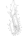
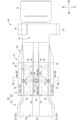
- FIG. 1 is a perspective view showing a terminal unit according to Embodiment 1 in a state where a male terminal and a female terminal are fitted together.
- FIG. 2 is a plan view of the terminal unit shown in FIG. 1.
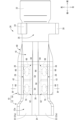
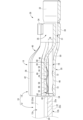
- FIG. 3 is a longitudinal sectional view of the terminal unit shown in FIG. 1, and is a sectional view taken along line III--III in FIG.
- FIG. 4 is an enlarged cross-sectional view of the IV-IV cross section in FIG.
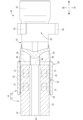
- FIG. 5 is a sectional view taken along line VV in FIG.
- FIG. 6 is a perspective view showing the female terminal constituting the terminal unit shown in FIG. 1 in an unfitted state with the male terminal.
- FIG. 7 is a diagram showing a vertical cross-sectional view of the female terminal shown in FIG.
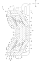
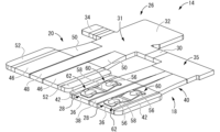
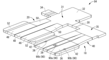
- FIG. 8 is a perspective view showing the female terminal shown in FIG. 6 in an unfolded state before bending.
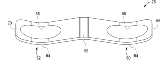
- FIG. 9 is a perspective view showing a contact forming metal fitting constituting the female terminal shown in FIG. 6.
- FIG. 10 is a perspective view showing the terminal unit according to Embodiment 2 in a state where a male terminal and a female terminal are fitted together.
- FIG. 11 is a plan view of the terminal unit shown in FIG. 10.
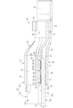
- FIG. 12 is a sectional view taken along line XII-XII in FIG.
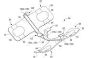
- FIG. 13 is a perspective view showing the female terminal main body constituting the female terminal shown in FIG. 10 in an unfolded state before bending.
- FIG. 14 is a perspective view showing a contact forming metal fitting constituting the female terminal shown in FIG. 10.
- the terminal unit of the present disclosure includes: (1) A male terminal having a plate shape and a female terminal connected to the male terminal, the female terminals being arranged opposite to each other across a male terminal press-fitting gap into which the male terminal is press-fitted.
- the male terminal has a first contact portion and a second contact portion that are inclined toward one side in the thickness direction of the male terminal on both sides of the plate width direction that intersects with the press-fitting direction into the male terminal press-fitting gap.
- the first contact portion of the female terminal faces the one surface of the male terminal in the plate thickness direction, and the first contact portion of the female terminal is arranged along the pair of inclined portions of the male terminal.
- the second contact portion of the female terminal has a pair of first inclined side edges that are inclined respectively, and the second contact portion of the female terminal faces the other surface of the male terminal in the plate thickness direction.
- a pair of second inclined side edges are respectively inclined along the inclined part, and at least one of the pair of first inclined side edges and the pair of second inclined side edges has the first inclined side edge.
- a contact forming metal fitting formed of a separate thin metal plate that is thinner than the edge and the second inclined side edge and easily deformable is fixed in a conductive manner, and the contact forming metal fitting is connected to the male terminal press-fit.
- the male terminal has a pair of first contact portions protruding toward the gap, and the male terminal is allowed to be press-fitted into the male terminal press-fitting gap by bending deformation of the pair of first contact portions, and the male terminal press-fitting gap is With the male terminal press-fitted into the male terminal, the elastic restoring force of the pair of first contact portions of the female terminal brings the pair of first contact portions into pressure contact with the pair of inclined portions of the male terminal, respectively; and the pair of sloped portions of the male terminal are held between the pair of first sloped side edges and the pair of second sloped side edges of the female terminal, respectively.
- the female terminal has a first contact portion and a second contact portion that are arranged opposite to each other across a male terminal press-fitting gap, and a male terminal is connected between the first contact portion and the second contact portion. It has a structure that holds the male terminal press-fitted into the terminal press-fitting gap.
- the male terminal has a pair of inclined parts that are inclined toward one side in the thickness direction of the male terminal on both sides of the male terminal in the board width direction, which is a direction that intersects with the direction of press-fitting into the male terminal press-fitting gap. ing.
- the first contact portion of the female terminal has a pair of first inclined side edges that face one side of the male terminal in the thickness direction and are respectively inclined along the pair of inclined portions of the male terminal.
- the second contact portion of the female terminal has a pair of second inclined side edges that face the other surface of the male terminal in the plate thickness direction and are respectively inclined along the pair of inclined portions of the male terminal.
- at least one of the pair of first sloped side edges and the pair of second sloped side edges is provided with a separate body that is thinner and easily deformable than the first sloped side edges and the second sloped side edge.
- a contact forming fitting formed of a thin metal plate is fixed.
- the contact forming metal fitting has a pair of first contact portions that protrude toward the male terminal press-fitting gap.
- the bending deformation of the pair of first contact portions allows the male terminal to be press-fitted into the male terminal press-fitting gap, while the male terminal is press-fitted into the male terminal press-fitting gap, and the pair of first contact portions of the female terminal Due to the elastic restoring force of the contact portions, the pair of first contact portions are brought into pressure contact with the pair of sloped portions of the male terminal, and the pair of sloped portions of the male terminal are brought into contact with the pair of first sloped side edges of the female terminal. can be respectively sandwiched between the second slanted side edges of the two sides.
- At least one of the pair of first sloped side edges and the pair of second sloped side edges is made of a separate piece of metal that is thinner and easily deformable than the first sloped side edges and the second sloped side edge. Since the pair of first contact portions formed by a thin plate are provided, the male terminal can be easily press-fitted into the male terminal press-fitting gap due to the bending deformation of the pair of first contact portions, reducing the insertion force. can be achieved. Moreover, due to the elastic restoring force of the pair of first contact portions, the pair of sloped portions of the male terminal press-fitted into the male terminal press-fitting gap can be moved between the pair of first sloped side edges and the pair of second sloped side edges of the female terminal.
- the pair of first contact portions are formed using a contact forming fitting formed of a separate thin metal plate that is thinner than the first inclined side edge and the second inclined side edge of the female terminal and is easily flexibly deformed. Because of this structure, compared to the case where the first contact is provided directly on the first inclined side edge and the second inclined side edge, the contact area of the first contact portion to the male terminal is increased, and the contact area of the male terminal is increased.
- first contact part can be provided with a separate contact forming metal fitting, the degree of freedom in designing the first contact part can be improved, and multiple contacts can be arranged in the optimal location and shape according to the usage conditions. It can also be easily installed in
- first inclined side edges and the pair of second inclined side edges “inclining respectively along the pair of inclined parts of the male terminal” means that the pair of first inclined side edges and the pair of second inclined side edges It is sufficient that the first inclined side edge and the second inclined side edge are inclined, and the inclined portion of the male terminal and the first/second inclined side edge do not necessarily have to be parallel.
- the angle of inclination of the first/second inclined side edges may be different from the angle of inclination of the inclined part of the male terminal within a range of about 0 to 10 degrees.
- each first contact portion may be provided on either one of the pair of first inclined side edges and the pair of second inclined side edges, or may be provided on both.
- the shape of each first contact portion is such that when pressed by the male terminal that is press-fitted into the male terminal press-fitting gap, it bends and deforms toward the outside of the male terminal press-fitting gap, and elastically returns toward the inside of the male terminal press-fitting gap. Any shape can be adopted as long as it does.
- the female terminal has a connecting plate portion that electrically connects the first contact portion and the second contact portion, and the second contact portion has an external connection portion.
- the contact forming fittings are fixed to the pair of first inclined side edges of the first contact portion of the female terminal, and the contact forming fittings are fixed to the pair of second inclined side edges of the second contact portion of the female terminal.
- a pair of second contact portions are provided in the portion, each of the second inclined side edges partially protruding toward the male terminal press-fitting gap, and the male terminal is inserted into the male terminal press-fitting gap.
- the pair of sloped portions of the male terminal are pressed against the pair of second contact portions of the female terminal due to the elastic restoring force of the first contact portion when the male terminal is press-fitted. preferable.
- the second contact part of the female terminal is provided with an external connection part to which an external wire terminal or circuit terminal is connected, and a second contact part is formed by partially protruding a part of the same second contact part. is provided at the second contact portion.
- the pair of inclined parts of the male terminal can be brought into pressure contact with the second contact part by the elastic restoring force of the first contact part, and with a small number of parts, the contact pressure between the male and female terminals can be ensured, and the contact pressure between the male and female terminals can be secured. It is possible to simultaneously achieve a reduction in contact resistance.
- the contact forming metal fitting is fixed to at least one of the pair of first inclined side edges and the pair of second inclined side edges by welding.
- it has a welded fixing part.
- a contact forming metal fitting is fixed to each first inclined side edge and/or each second inclined side edge by welding at a welding fixing portion.
- the contact forming metal fitting of the female terminal has a band shape extending in the press-fitting direction of the male terminal into the male terminal press-fitting gap, and the contact forming fitting has a longitudinal direction.
- the welding fixing part is provided at the center of the welding part, and the front protruding tongue piece and the rear protruding tongue piece are provided in a cantilever shape from the welding fixing part toward both ends in the longitudinal direction.
- the protruding tongue piece and the rear protruding tongue piece extend in the longitudinal direction in a curved shape convex toward the male terminal press-fitting gap when viewed from the side, and each of the front protruding tongue piece and the rear protruding tongue piece It is preferable that the first contact portion is provided at an intermediate portion in the longitudinal direction.
- the contact forming metal fitting extends in the shape of a band in the direction in which the male terminal is press-fitted, and a welding fixing part is provided at the central portion in the longitudinal direction.
- a forward protruding tongue piece and a rear protruding tongue piece can be made to protrude in a cantilever shape from the welding fixing part toward both sides in the longitudinal direction (the direction in which the male terminal is press-fitted), and the first contact portions are respectively provided thereon. It is being Therefore, the ability of the first contact portion to follow the displacement of the male terminal in the front-rear direction (press-fitting direction) can be advantageously improved.
- the front protruding tongue piece and the rear protruding tongue piece extend in the longitudinal direction in a curved shape that is convex toward the male terminal press-fitting gap when viewed from the side, and the front protruding tongue piece and the rear protruding tongue piece extend in the longitudinal direction.
- a first contact portion is provided at an intermediate portion of the contact portion.
- the amount of protrusion of the protruding end of the rear protruding tongue into the male terminal press-fitting gap is smaller than that of the first contact part, so that when the male terminal is inserted, the male terminal It can also perform the function of guiding the male terminal toward the press-fit gap while reducing the risk of choking.
- the contact forming metal fitting is configured to provide at least one of the pair of first inclined side edges and the pair of second inclined side edges, Preferably, it has a caulking fixing part that is fixed by caulking.
- a contact forming metal fitting is fixed to each first inclined side edge and/or each second inclined side edge by caulking at a caulking fixing portion. Thereby, the first contact portion of the contact forming metal fitting can be easily fixed while ensuring conductivity to each first inclined side edge and/or each second inclined side edge.
- the contact forming fitting of the female terminal has a band shape extending in the direction of press-fitting the male terminal into the male terminal press-fitting gap, and the contact forming fitting has a longitudinal direction.
- the caulking fixing part is provided at the center of the caulking fixing part, and the front protruding tongue piece and the rear protruding tongue piece are provided in a cantilever shape from the caulking fixing part toward both ends in the longitudinal direction.
- the protruding tongue piece and the rear protruding tongue piece extend in the longitudinal direction in a curved shape convex toward the male terminal press-fitting gap when viewed from the side, and each of the front protruding tongue piece and the rear protruding tongue piece It is preferable that the first contact portion is provided at an intermediate portion in the longitudinal direction.
- the contact forming metal fitting extends in the shape of a band in the direction in which the male terminal is press-fitted, and a caulking fixing part is provided at the center portion in the longitudinal direction.
- a forward protruding tongue piece and a rear protruding tongue piece can be made to protrude in a cantilever shape from the caulking fixing part toward both sides in the longitudinal direction (the direction in which the male terminal is press-fitted), and a first contact part is provided there respectively. It is being Therefore, the ability of the first contact portion to follow the displacement of the male terminal in the front-rear direction (press-fitting direction) can be advantageously improved.
- the front protruding tongue piece and the rear protruding tongue piece extend in the longitudinal direction in a curved shape that is convex toward the male terminal press-fitting gap when viewed from the side, and the front protruding tongue piece and the rear protruding tongue piece extend in the longitudinal direction.
- a first contact portion is provided at an intermediate portion of the contact portion.
- the amount of protrusion of the protruding end of the rear protruding tongue into the male terminal press-fitting gap is smaller than that of the first contact part, so that when the male terminal is inserted, the male terminal It can also perform the function of guiding the male terminal toward the press-fit gap while reducing the risk of choking.
- the male terminal has a central flat portion disposed between the pair of sloped portions in the plate width direction
- the female terminal The first contact portion has a first flat portion that is disposed between the pair of first inclined side edges in the board width direction and extends along and opposite to the central flat portion of the male terminal.
- the second contact portion of the female terminal is arranged between the pair of second inclined side edges in the plate width direction, and has a second contact portion extending along opposite to the central flat portion of the male terminal.
- it has a flat portion.
- the male terminal has a central flat part and a pair of sloped parts on both sides of the central flat part that are inclined to the same side in the thickness direction, and the first contact part and the second contact part of the female terminal are arranged on both sides of the male terminal in the thickness direction. and has a shape similar to the male terminal. That is, the first contact portion includes a first flat portion that extends along the central flat portion of the male terminal, and a first slope side that is arranged on both sides of the first flat portion and slopes along the pair of sloped portions of the male terminal.
- the second contact portion has a second flat portion extending along the central flat portion of the male terminal, and a second flat portion extending along a pair of inclined portions disposed on both sides of the second flat portion.
- the female terminal of the present disclosure includes: (8) Used in the terminal unit according to any one of (1) to (7) above.
- any of the effects (1) to (7) above can be achieved by connecting the male terminal to form a terminal unit.
- the male terminal of the present disclosure includes: (9) Used in the terminal unit according to any one of (1) to (7) above.
- any of the effects (1) to (7) above can be achieved by connecting to the female terminal to form a terminal unit.
- the terminal unit 10 includes a plate-shaped male terminal 12 and a female terminal 14 connected to the male terminal 12.
- the female terminal 14 has a first contact portion 18 and a second contact portion 20 that are arranged to face each other across a male terminal press-fit gap 16 into which the male terminal 12 is press-fitted. Then, the male terminal 12 is press-fitted into the male terminal press-fit gap 16 in the female terminal 14 and comes into contact with the first contact portion 18 and the second contact portion 20, so that the male terminal 12 and the female terminal 14 are electrically connected. It is designed to be connected to.
- terminal unit 10 can be arranged in any direction; however, in the following, upper means the upper side in FIG. 4, lower means the lower side in FIG. 4, and left means the upper side and the right side in FIG.
- the direction will be described as the lower side in FIG. 2, the front as the right side in FIG. 2, and the rear as the left side in FIG.
- a plurality of identical members only some of the members may be labeled with numerals, and the numerals may be omitted for other members.
- the male terminal 12 has a plate shape as a whole, and is constructed using a flat metal fitting (not shown).
- the flat metal fitting has a generally rectangular shape as a whole, has a predetermined plate width and thickness, and extends straight.
- the male terminal 12 is press-fitted into the male terminal press-fitting gap 16 in the female terminal 14 from the rear toward the front, and the part of the male terminal 12 that is press-fitted into the male terminal press-fitting gap 16 (the front part ) has a tapered shape compared to the rear part (see Figures 1, 2, etc.).
- the male terminal 12 is electrically conductive and is made of a metal with low electrical resistance, such as copper, copper alloy, aluminum, or aluminum alloy.
- a pair of inclined portions 22 are formed at both end portions in the plate width direction of the male terminal 12.
- 22 are provided. That is, in the male terminal 12, a pair of inclined portions are provided on both sides in the board width direction, which is a direction that intersects with the direction of press-fitting into the male terminal press-fitting gap 16 (direction from the back to the front), which is a direction orthogonal to the direction in the first embodiment. 22, 22 are provided.
- a central flat part 24 that spreads flat is provided at the center portion of the male terminal 12 in the board width direction located between the pair of inclined parts 22 , 22 .
- the pair of inclined portions 22, 22 may be provided over the entire length of the male terminal 12 in the longitudinal direction, or may be provided over the entire length of the male terminal 12 in the male terminal press-fitting gap 16 (the tapered front portion). ) may be provided only.
- the plate thickness of the male terminal 12 is approximately constant, and the thickness of the pair of inclined parts 22, 22 and the central flat part 24 are each A (see FIGS. 4 and 5). The thickness dimensions of the sloped portions 22, 22 and the central flat portion 24 may be different from each other.
- the angle of inclination of the pair of inclined parts 22, 22 with respect to the central flat part 24 is ⁇ 1 (see FIG. 4).
- the angles of inclination with respect to the flat portion 24 are the same magnitude ( ⁇ 1), but the angles of inclination on both the left and right sides may be different from each other.
- the inclination angle ⁇ 1 of the pair of inclined parts 22, 22 with respect to the central flat part 24 is not limited, but is preferably, for example, 5° or more and 45° or less, more preferably 10° or more and 30°. The following shall apply.
- the inclination angle ⁇ 1 of the inclined portion 22 By setting the inclination angle ⁇ 1 of the inclined portion 22 to 5° or more, the displacement of the male terminal 12 outward in the board width direction is suppressed even when external force is input to the male terminal 12 in the board width direction outward. can do.
- the inclination angle ⁇ 1 of the inclination portion 22 By setting the inclination angle ⁇ 1 of the inclination portion 22 to 45° or less, the vertical dimension of the male terminal 12 and, by extension, the terminal unit 10 can be kept small.
- the rear side of the tapered front portion extends straight, and even if a pair of inclined portions 22, 22 are provided and the male terminal 12 extends rearward as shown in FIG.
- the pair of inclined portions 22, 22 may not be provided, and may have a substantially flat plate shape and extend toward the rear side.
- the rear portion of the male terminal 12 has an electric wire fixed thereto by, for example, crimping or welding, or has a bolt insertion hole so that it can be fixed to a terminal portion of a device.
- the female terminal 14 includes a female terminal body 26 made of a single metal flat plate, and a pair of contact forming fittings 28, 28 fixed to the female terminal body 26.
- the female terminal 14 is formed by bending the female terminal main body 26 to which each contact forming metal fitting 28 is fixed into a predetermined shape described below. That is, the female terminal main body 26 has the first contact portion 18 and the second contact portion 20 that constitute the male terminal press-fitting gap 16, and further allows electrical conduction between the first contact portion 18 and the second contact portion 20. It has a connecting plate part 30 that is connected to.
- the female terminal main body 26 has an external connection portion 32 to which a core wire of an electric wire (not shown) is fixed, or a bus bar or the like constituting an internal circuit of a device (not shown) is connected.
- an external connection portion 32 is provided at the front end portion 31 of the second contact portion 20 .
- a caulking piece 34 is formed on the front end 31 of the second contact portion 20, and the caulking piece 34 allows the female terminal body 26 bent into a predetermined shape to be connected to the first contact portion 18 and the second contact portion. 20 is prevented from being displaced in the opening direction (separating displacement).
- the female terminal main body 26 is made of various metal materials that are conductive and can be press-worked, punched, etc., such as brass, copper, copper alloy, aluminum, aluminum alloy, etc. can be formed. In the first embodiment, the female terminal main body 26 is made of pure copper with excellent conductivity.
- the first contact portion 18 and the second contact portion 20 before bending each have a substantially rectangular shape in plan view, and are lined up in the width direction (horizontal direction) of each plate.
- the front end portion 35 of the first contact portion 18 and the front end portion 31 of the second contact portion 20 are connected by the connecting plate portion 30.
- a caulking piece 34 is provided protruding from the front end 31 of the second contact portion 20 on the opposite side (left side) to the side where the connecting plate portion 30 is provided. Then, the connecting plate portion 30 is bent so that the first contact portion 18 and the second contact portion 20 face each other in the vertical direction and is caulked and fixed by the caulking piece 34, so that the female terminal body 26 is bent in a predetermined direction.
- one longitudinal end side (each front end 35, 31) of the first contact part 18 and second contact part 20 is connected by the connecting plate part 30, and each of the connected front ends
- the first contact portion 18 and the second contact portion 20 protrude rearward from the portions 35 and 31 in a cantilever shape, respectively.
- the front end portion of the second contact portion 20 extends further forward than the connection portion with the first contact portion 18, forming a substantially rectangular flat external connection portion 32.
- the first contact portion 18 before bending has a substantially rectangular flat plate shape as a whole, and extends substantially straight in the front-rear direction.
- the shape of the first contact portion 18 after bending will be described below.
- the first contact portion 18 has a pair of first inclined sides that are respectively inclined along a pair of inclined parts 22, 22 of the male terminal 12, facing one surface (upper surface 12a) of the male terminal 12 in the plate thickness direction. It has edges 36,36. These first inclined side edges 36 are formed by bending both end portions of the first contact portion 18 in the plate width direction (left and right direction) toward one side (upward) in the plate thickness direction with respect to the center portion in the plate width direction. It is formed.
- a first flat portion 38 is provided that extends flat.
- each first inclined side edge portion 36 is provided over a predetermined length from the rear end of the first contact portion 18.
- Each first inclined side edge portion 36 is inclined at a predetermined inclination angle ⁇ 2 (see FIG. 4) with respect to the first flat portion 38 at the rear end portion of the first contact portion 18.
- ⁇ 2 a predetermined inclination angle
- the angles of inclination of the first inclined side edge 36 of the first inclined side edge 36 of the first flat part 38 are the same ( ⁇ 2), but the angles of inclination on both the left and right sides may be different from each other.
- the front end portion 35 of the first contact portion 18 is located below the first flat portion 38 provided at the rear portion of the first contact portion 18, and the front end portion 35 of the first contact portion 18 is located below the first flat portion 38 provided at the rear portion of the first contact portion 18.
- a transition section 40 is provided that gradually curves downward toward the front. Note that the first inclined side edges 36 are not provided at both left and right end portions of the front end portion 35 of the first contact portion 18 , and the front end portion 35 of the first contact portion 18 is provided with the first flat portion 38 . It spreads out almost parallel to the other.
- the left and right end portions of the front end portion 35 have an inclination angle of 0 with respect to the left and right center portion, and the left and right end portions of the transition portion 40 not only change downward toward the front but also move toward the left and right center.
- the inclination angle for the portion is made to gradually become smaller from ⁇ 2 to 0.
- each first inclined side edge 36 includes: First edge portions 42, 42 are provided that extend substantially parallel to the first flat portion 38.
- Each first edge portion 42 is provided over the entire length of each first inclined side edge portion 36 in the length direction (front-back direction), and extends in the horizontal direction (direction perpendicular to the up-down direction).
- the inner surface of the rear end portion of the first contact portion 18 is gradually separated from the second contact portion 20 facing in the vertical direction toward the rear, that is, toward the front.
- a guiding surface 44 is provided that gradually approaches the male terminal press-fitting gap 16 inward.
- a guiding surface 54 is provided on the inner surface of the rear end of the second contact portion 20, and when the male terminal 12 is press-fitted into the female terminal 14, each of the guiding surfaces 44, 54 Accordingly, the male terminal 12 is guided to the male terminal press-fitting gap 16 in the female terminal 14.
- Such guiding surfaces 44, 54 are formed, for example, by press working or the like when the female terminal main body 26 is in the unfolded state shown in FIG. Therefore, the guiding surface 44 is provided over approximately the entire length of the first contact portion 18 in the left-right direction, that is, across the first end edges 42 on both the left and right sides, the first inclined side edges 36, and the first flat portion 38. ing.
- the second contact portion 20 before bending has a substantially rectangular flat plate shape as a whole, and extends substantially straight in the front-rear direction.
- the shape of the second contact portion 20 after bending will be described below.
- the second contact portion 20 has a pair of second inclined sides that are respectively inclined along a pair of inclined parts 22, 22 of the male terminal 12, facing the other surface (lower surface 12b) of the male terminal 12 in the plate thickness direction. It has edges 46,46. These second inclined side edges 46 are formed by bending both end portions of the second contact portion 20 in the plate width direction (left and right direction) toward one side (upward) in the plate thickness direction with respect to the center portion in the plate width direction. It is formed.
- a second flat portion 48 is provided that extends flat.
- each second inclined side edge 46 is provided over a predetermined length from the rear end of the second contact portion 20.
- Each second inclined side edge portion 46 is inclined at a predetermined inclination angle ⁇ 3 (see FIG. 4) with respect to the second flat portion 48 at the rear end portion of the second contact portion 20.
- the angles of inclination of the second inclined side edges 46 with respect to the second flat part 48 are the same ( ⁇ 3), but the angles of inclination on both the left and right sides may be different from each other.
- each first inclined side edge portion 36 with respect to the first flat portion 38 may be the same or different with respect to the inclination angle ⁇ 1 of each inclined portion 22 of the male terminal 12 with respect to the central flat portion 24.
- the difference is within 10°.
- the inclination angle ⁇ 3 of each second inclined side edge portion 46 with respect to the second flat portion 48 may be the same or different from the inclination angle ⁇ 1 of each inclined portion 22 of the male terminal 12 with respect to the central flat portion 24. Even in this case, it is preferable that the angular difference is within 10°.
- each first inclined side edge portion 36 with respect to the first flat portion 38 is approximately equal to the inclination angle ⁇ 3 of each second inclined side edge portion 46 with respect to the second flat portion 48. . Therefore, in the first embodiment, the first sloped side edge 36 and the second sloped side edge 46 on the left side extend substantially parallel to each other, and the first sloped side edge 36 and the second sloped side edge 46 on the right side extend substantially parallel to each other. The side edges 46 extend substantially parallel to each other.
- the front end portion 31 of the second contact portion 20 is located at approximately the same vertical position as the second flat portion 48 of the second contact portion 20, and is located at both end portions of the second contact portion 20 in the left and right direction in the middle portion of the second contact portion 20 in the front and back direction.
- Second edge portions 52, 52 are provided that bend upward.
- Each second edge portion 52 is provided over the entire length of each second inclined side edge portion 46 in the length direction (front-back direction), and extends in the vertical direction. As shown in FIG. 1, etc., when the female terminal main body 26 is bent, each first end edge 42 and each second end edge 52 either come into contact with each other in the vertical direction or are slightly separated from each other. It is designed to face each other with a
- the inner surface of the rear end portion of the second contact portion 20 is gradually separated from the first contact portion 18 facing in the vertical direction toward the rear, that is, toward the front.
- a guiding surface 54 is provided that gradually approaches the inner male terminal press-fitting gap 16 as the position increases.
- the guiding surface 54 is formed by press working or the like when the female terminal main body 26 is in the unfolded state shown in FIG. It is provided across the entire length, that is, the second end edges 52 on both the left and right sides, the second inclined side edges 46 and the second flat portion 48 .
- a pair of contact forming fittings 28, 28 can be electrically connected to at least one of the pair of first inclined side edges 36, 36 and the pair of second inclined side edges 46, 46, respectively. is fixed.
- Each contact forming fitting 28 is formed of a thin metal plate separate from each first inclined side edge 36 and each second inclined side edge 46. It is thinner than the side edge portion 46 and can be easily deformed (elastically deformed).
- the pair of contact forming metal fittings 28, 28 are fixed to the inner surfaces of the pair of first inclined side edges 36, 36, respectively.
- the pair of contact forming fittings 28, 28 each have a pair of first contact portions 56, 56 that protrude toward the male terminal press-fitting gap 16.
- first contact portions 56, 56 that protrude toward the male terminal press-fitting gap 16.
- the contact forming fitting 28 as a whole has a band shape extending in the front-rear direction, which is the direction in which the male terminal 12 is press-fitted into the male terminal press-fit gap 16.
- the contact forming metal fitting 28 may be made of a metal that has conductivity and spring properties, and in the first embodiment, it is made of a copper alloy that has spring properties.
- the contact forming fitting 28 is fixed to the first inclined side edge 36 by welding, and the welding fixing part 58 is provided at the longitudinal (front-back direction) central portion of the contact forming fitting 28. ing.
- the welding fixing portion 58 extends substantially flat in the contact forming fitting 28 and is formed over substantially the entire length of the contact forming fitting 28 in the width direction (left and right direction). Note that the method of welding the contact forming metal fitting 28 to the first inclined side edge 36 is not limited, but laser welding or the like may be employed, for example.
- the contact forming metal fitting 28 has a front protruding tongue piece 60 and a rear protruding tongue piece 62 that protrude in a cantilever shape from the welding fixing portion 58 toward both ends in the longitudinal direction (front-back direction).
- the front protruding tongue piece 60 and the rear protruding tongue piece 62 have a curved shape convex toward the male terminal press-fitting gap 16 in a side view and extend in the front-rear direction.
- a first contact portion 56 is provided at an intermediate portion of each of the front protruding tongue piece 60 and the rear protruding tongue piece 62 in the front-rear direction.
- the front protruding tongue piece 60 has a shape that is curved as a whole so as to be convex on one side in the thickness direction of the contact forming metal fitting 28, and has a bent part 64 at the middle part in the front and back direction.
- the forward protruding tongue piece 60 extends forward from the welding fixing part 58 in a direction that gradually separates from the welding fixing part 58 in the thickness direction of the contact forming metal fitting 28, and is bent at the bending part 64. As it approaches the front, it extends in the thickness direction of the contact forming metal fitting 28 in a direction that gradually approaches the welding fixing part 58.
- a first contact portion protrudes in the same direction as the curved convex direction (one of the thickness directions of the contact forming fittings 28) of the forward protruding tongue piece 60 in the width direction (left and right direction) center portion of the forward protruding tongue piece 60. 56 are provided.
- the first contact portion 56 is formed to have a curved arc shape in the longitudinal section of the contact forming metal fitting 28 shown in FIG. That is, the first contact portion 56 has a substantially elliptical shape in which the length dimension (front-back dimension) is larger than the width dimension (horizontal dimension) in plan view (vertical projection). .
- Such a first contact portion 56 may be formed by, for example, punching out, and the front protruding tongue piece 60 has a first contact portion 56 and a surface opposite to the side from which the first contact portion 56 protrudes.
- a recess 66 is formed at a corresponding position.
- the rear protruding tongue piece 62 has the same shape as the front protruding tongue piece 60. That is, the rear protruding tongue piece 62 has a shape that is curved as a whole so as to be convex in the same direction as the front protruding tongue piece 60, and has a bent part 64 at an intermediate portion in the front-rear direction.
- a first contact portion protrudes in the same direction as the first contact portion 56 of the front protruding tongue piece 60 at the center portion in the left-right direction of the rear protruding tongue piece 62, spanning both front and rear portions including the bent portion 64. 56 are provided. Therefore, in the contact forming metal fitting 28, the pair of first contact portions 56, 56 are provided spaced apart from each other in the front-back direction. Further, a recess 66 is formed at a position corresponding to the first contact portion 56 on the surface of the rear protruding tongue piece 62 opposite to the side from which the first contact portion 56 protrudes.
- each contact forming fitting 28 having such a shape, for example, when the female terminal main body 26 is in the unfolded state, each contact forming fitting 28 is connected to a portion that constitutes the inner surface of each first inclined side edge 36.
- the welding fixing portions 58 of the forming fittings 28 are overlapped and fixed by laser welding.
- the forward protruding tongue piece 60 and the rear protruding tongue piece 62 are curved upwardly, and each first contact portion 56 protrudes upwardly.
- the female terminal body 26 to which each contact forming metal fitting 28 is fixed is bent as described above to form the female terminal 14, so that each first contact portion 56 is bent downward, specifically, at the lower right and It protrudes toward the lower left.
- each contact forming metal fitting 28 is fixed to each first inclined side edge 36 that is spaced apart from each other in the left-right direction, a total of four first contact parts 56 are provided in the first contact part 18. are provided spaced apart from each other in the front-rear direction and left-right direction.
- each contact forming metal fitting 28 is fixed to the inner surface of each first inclined side edge 36
- the front end portion 68 of the front protruding tongue piece 60 and the rear protruding tongue piece The rear end portion 70 of each of the first inclined side edges 36 is slightly spaced apart from the inner surface of each first inclined side edge portion 36, and the front end portion 68 of the front protruding tongue piece 60 and the rear end portion 70 of the rear protruding tongue piece 62 are respectively free ends.
- the male terminal 12 is press-fitted into the male terminal press-fitting gap 16, and the upper surface 22a of each inclined portion 22 of the male terminal 12 becomes the first contact point of each of the forward protruding tongue piece 60 and the rear protruding tongue piece 62.
- the forward protruding tongue piece 60 and the rear protruding tongue piece 62 are elastically deformed in a direction in which the protruding dimension of each first contact portion 56 within the male terminal press-fitting gap 16 becomes smaller.
- the front end portion 68 of the front protruding tongue piece 60 and the rear end portion 70 of the rear protruding tongue piece 62 are respectively displaced forward and rearward than before the elastic deformation, and are adapted to be elongated and deformed so that their respective lengths in the front-rear direction become larger.
- each contact forming metal fitting 28 is fixed to the inner surface of each first inclined side edge 36
- the rear end portion of the rear protruding tongue piece 62 extends from the first contact portion 56 to the rear end.
- the portion reaching 70 is inclined in a direction away from the opposing second inclined side edge 46 toward the rear.
- each rearward protruding tongue piece 62 from the rear end part 70 to the first contact part 56, as it goes forward, it gradually approaches the inner male terminal press-fit gap 16, and depending on this part, A guiding effect of the male terminal 12 toward the male terminal press-fitting gap 16 can be exerted.
- each of the second contact parts 72 has a front-rear dimension which is the press-fitting direction of the male terminal 12, which is larger than a left-right dimension, and a protruding tip surface has a curved surface. has been done.
- each second contact portion 72 is not limited, in the first embodiment, as shown in FIG.
- the outer part in the direction is a curved surface having a relatively large inclination angle with respect to the inner surface of each second inclined side edge 46
- the inner part in the front-rear direction is a curved surface with a relatively large angle of inclination with respect to the inner surface of each second inclined side edge 46. It is a curved surface with a relatively small inclination angle.
- each of the second contact portions 72 has the same shape, and is provided at two locations separated from each other in the front-rear direction, which is the press-fitting direction of the male terminal 12, on each of the second inclined side edges 46. . Therefore, the second contact portion 20 is provided with a total of four second contact portions 72 spaced apart from each other in the front-rear direction and the left-right direction.
- first contact portions 56 and the second contact portions 72 overlap each other. Furthermore, in the projection of each first inclined side edge 36 and each second inclined side edge 46 in the thickness direction, the top of each first contact portion 56 and the top of each second contact portion 72 are positioned shifted from each other. The first contact portions 56 and the second contact portions 72 partially overlap.
- each first contact portion 56 is elastically deformed
- the thickness direction of each inclined portion 22 of the male terminal 12 that is, each first inclined side edge 36 and each In the thickness direction of the second inclined side edge 46
- the distance between the top of each first contact portion 56 and each second contact portion 72 is B (see FIG. 7).
- the separation distance B between the top of each first contact portion 56 and the top of each second contact portion 72 is smaller than the plate thickness dimension A of the male terminal 12 (B ⁇ A), so that the male terminal is press-fitted.
- the male terminal 12 can be press-fitted into the gap 16.
- each of the second contact portions 72 is formed by, for example, performing press working on each of the second inclined side edges 46, and as shown in FIG.
- a recessed portion 74 that opens downward is formed at a position corresponding to each second contact portion 72 on the outer surface (lower surface) of.
- the flat metal plate constituting the female terminal body 26 is prepared in an expanded state, and each contact forming metal fitting 28 is attached to the inner surface of each first inclined side edge 36 of the first contact portion 18.
- the welding fixing parts 58 in are overlapped and fixed by laser welding.
- each of the second inclined side edges 46 of the second contact portion 20 is subjected to press working or the like to form each of the second contact portions 72 on each of the second inclined side edges 46 .
- the female terminal main body 26 to which each contact forming metal fitting 28 is fixed is bent into the above-described shape to form the female terminal 14 shown in FIG. 6.
- the male terminal 12 bent into the above-described shape and the female terminal 14 are brought close to each other in the front-rear direction. Then, the male terminal 12 is inserted into the male terminal press-fitting gap 16 in the female terminal 14 from behind. At this time, since the separation distance B between each first contact portion 56 and each second contact portion 72 is smaller than the plate thickness dimension A of the male terminal 12, the male terminal is inserted in a press-fit state. Note that the separation distance between the first flat part 38 and the second flat part 48 is made sufficiently larger than the plate thickness dimension A of the male terminal 12 (central flat part 24), and the central flat part 24 is separated from the first flat part 38. It is inserted between the first flat part 38 and the second flat part 48 in the vertical direction without contacting either the first flat part 38 or the second flat part 48 .
- each first contact portion 56 and the upper surface 22a of each inclined portion 22 come into contact with each other, and Each second contact portion 72 and the lower surface 22b of each inclined portion 22 are in contact with each other. Since each contact forming metal fitting 28 is thin and prone to elastic deformation, when the male terminal 12 is press-fitted into the male terminal press-fitting gap 16, each front protruding tongue piece 60 and each rear protruding tongue piece 62 Each first contact portion 56 is elastically deformed in a direction in which the protruding dimension of each first contact portion 56 within the gap 16 becomes smaller.
- each first contact portion 56 is pressed against the upper surface 22a of each inclined portion 22. Further, each inclined portion 22 urged downward by each first contact portion 56 is pressed against each second contact portion 72 .
- each first contact portion 56 is pressed against each inclined portion 22 of the male terminal 12 due to the elastic restoring force of each first contact portion 56.
- each inclined portion 22 of the male terminal 12 is held between each first inclined side edge 36 and each second inclined side edge 46 of the female terminal 14.
- each inclined portion 22 is brought into pressure contact with each second contact portion 72 due to the elastic restoring force of each first contact portion 56.
- each inclined portion 22 is held between each first inclined side edge 36 and each second inclined side edge 46, respectively.
- the male terminal 12 is press-fitted into the male terminal press-fitting gap 16 in the female terminal 14, and the male terminal 12 and the female terminal 14 are electrically connected, thereby completing the terminal unit 10.
- a pressing force F1 by the first contact portion 56 (see FIG. 4) and a pressing force F2 by the second contact portion 72 (from each inclined portion 22) are applied.
- the reaction force against the pressing force applied to each second contact portion 72 acts in the same direction as the thickness direction of each inclined portion 22, so that the first and second contact portions 56,
- Each inclined portion 22 is stably held by the slanted portions 72, so that the male terminal 12 and the female terminal 14 can be electrically connected to each other more reliably.
- the direction in which the pressing force F1 by the first contact portion 56 acts and the direction in which the pressing force F2 by the second contact portion 72 acts are opposite to each other in the thickness direction of each inclined portion 22.
- the pressing force F1 by the first contact portion 56 acts on both end portions in the left and right direction of each inclined portion 22, but the pressing force F2 by the second contact portion 72 is applied by the pressing force F1. It acts inward in the left and right direction than the part that acts. This prevents the pressing forces F1 and F2 from both the upper and lower sides from acting on the same position on each inclined portion 22.
- insertion resistance can also be reduced.
- the pressing force F1 by the first contact portion 56 acts as a downward component force F1a and an outward component force F1b in the left-right direction
- the pressing force F1 by the second contact portion 72 acts as a component force F1a downward and a component force F1b outward in the left-right direction
- F2 acts as an upward component force F2a and an inward component force F2b in the left-right direction.
- the displacement of the male terminal 12 due to the external force inputted by the force F1b) and the component force F2b inward in the left-right direction is suppressed.
- the downward force F1a by the first contact part 56 and the upward force F2a by the second contact part 72 are opposed to each other in the vertical direction, vertical displacement in the male terminal 12 is also suppressed more reliably.
- displacement of the male terminal 12 with respect to the female terminal 14 is suppressed, and the conduction state between the male terminal 12 and the female terminal 14 can be stably maintained.
- these pressing forces F1 and F2 are generated by the elastic restoring force of each first contact portion 56, and each contact forming metal fitting 28 having each first contact portion 56 is applied to both left and right sides of the first contact portion 18. It is set in. As a result, the pressing forces F1 and F2 on the left side can be obtained by the left contact forming metal fittings 28 (each first contact part 56), and the pressing forces F1 and F2 on the right side can be obtained by the right contact forming metal fittings 28. (Each first contact portion 56). As a result, it is also possible to set the magnitudes of the left and right pressing forces F1 and F2 separately.
- each contact forming metal fitting 28 that is thin and easily elastically deformable is fixed to each first inclined side edge 36 that constitutes the male terminal press-fitting gap 16, and each contact forming metal fitting 28 is The male terminal 12 is press-fitted into the male-terminal press-fitting gap 16 while being accompanied by elastic deformation of each first contact portion 56 formed in the male-terminal press-fitting gap 16 . Thereby, insertion resistance when inserting the male terminal 12 into the male terminal press-fitting gap 16 can be reduced.
- each first contact portion 56 By deforming following the displacement of the male terminal 12, the state in which each inclined portion 22 is held between each first contact portion 56 and each second contact portion 72 can be stably maintained. As a result, when an external force is applied to the male terminal 12, the possibility that the electrical connection between the male terminal 12 and the female terminal 14 will deteriorate can be reduced.
- each contact forming metal fitting 28 exerting each pressing force F1, F2 on each inclined part 22 is provided inside the male terminal press-fitting gap 16, for example, each pressing force F1, F2 on each inclined part It is also possible to avoid increasing the size of the female terminal 14 and, by extension, the terminal unit 10, compared to the case where the spring member exerting this effect is provided outside the male terminal press-fitting gap.
- each contact forming metal fitting 28 is fixed in the first contact part 18 to form each first contact part 56, and each second contact part is integrally formed in the second contact part 20. 72 is formed. Further, the second contact portion 20 is provided with an external connection portion 32 at the front end portion to which an external electric wire or the like is connected. That is, it is possible to form each contact forming metal fitting 28 and the female terminal body 26 with different materials, and while forming each contact forming metal fitting 28 with a material that has conductivity and spring properties, it is possible to form the female terminal body 26 with a more It can be made of a material with excellent conductivity.
- each of the second contact portions 72 and the external connection portion 32 are formed in the female terminal main body 26 (second contact portion 20) which has better conductivity, a conductive path from an external electric wire etc. to the male terminal 12 is formed. can also be set short, improving conductive performance.
- Each contact forming metal fitting 28 includes a welding fixing portion 58 that is fixed to each first inclined side edge 36 by welding. As a result, each contact forming fitting 28 is fixed to each first inclined side edge 36 in a small space while suppressing the influence on conductive performance. be able to.
- each contact forming metal fitting 28 has a welded fixing part 58 in the central part in the longitudinal direction (front-back direction), and a front part that protrudes like a cantilever from the welded fixing part 58 toward both ends in the longitudinal direction. It has a protruding tongue piece 60 and a rear protruding tongue piece 62.
- both the front protruding tongue piece 60 and the rear protruding tongue piece 62 can be stably elastically deformed. Therefore, each first contact portion 56 can be stably deformed to follow the displacement of the male terminal 12.
- each first contact portion 56 is provided at an intermediate portion in the longitudinal direction (front-rear direction) of the front protruding tongue piece 60 and the rear protruding tongue piece 62 .
- each forward protrusion The first contact portion 56 on the tongue piece 60 and the first contact portion 56 on each rearward protruding tongue piece 62 can be stably brought into contact with the male terminal 12. Therefore, the state in which the male terminal 12 is held between each first contact portion 56 and each second contact portion 72 can be maintained more stably.
- the male terminal 12 includes a pair of sloped parts 22, 22 and a central flat part 24 between each sloped part 22.
- the female terminal 14 includes a pair of first inclined side edges 36, 36, a first flat portion 38 between each of the first inclined side edges 36, and a pair of second inclined side edges 36. 46, 46, and a second flat portion 48 between each second sloped side edge 46.
- each inclined portion 22 is sandwiched between each first inclined side edge 36 and each second inclined side edge 46, so that an external force in the left and right direction is applied to the male terminal 12, as described above. displacement associated with this can be effectively suppressed.
- the male terminal 12 and the male terminal press-fitting gap 16 correspond to each other, it is possible to suppress the increase in size of the female terminal 14 and to prevent the size of the female terminal 14 from increasing. By avoiding contact with the male terminal 12 at the male terminal 12, it is possible to reduce the possibility that the insertion resistance of the male terminal 12 into the male terminal press-fitting gap 16 will increase.
- FIGS. 10 to 14 a terminal unit 80 according to a second embodiment of the present disclosure will be described using FIGS. 10 to 14.
- the second embodiment also employs a male terminal 12 having the same shape as the first embodiment, and the terminal unit 80 is configured by press-fitting the male terminal 12 into the male-terminal press-fitting gap 16 in the female terminal 82.
- the female terminal 82 of the second embodiment has the same basic structure as the female terminal 14 of the first embodiment, but in the female terminal 14 of the first embodiment, a pair of contact forming fittings 28, 28 was fixed by welding, whereas in the female terminal 82 of the second embodiment, one contact forming metal fitting 86 is fixed to the female terminal main body 84 by caulking.
- the female terminal main body 84 is shown in an unfolded state before being bent. Further, in FIG. 14, the contact forming metal fitting 86 is shown fixed to the bent female terminal main body 84 (the female terminal main body 84 is not shown), and before the male terminal 12 is inserted. The state before the contact forming metal fittings 86 (each of the forward protruding tongue pieces 92 and each of the rear protruding tongue pieces 94 described later) is elastically deformed is shown.
- the female terminal 82 of the second embodiment and the female terminal 14 of the first embodiment will be explained, and in the drawings, substantially the same members and parts as those of the first embodiment will be described. Detailed explanation will be omitted by assigning the same reference numerals as 1.
- a contact forming metal fitting 86 having a first contact portion 88 is fixed to the first contact portion 18 .
- the contact forming fitting 86 is fixed to the first contact portion 18 by caulking, and is located at the center of the first flat portion 38 and each first inclined side edge portion 36 in the front-rear direction in the first contact portion 18.
- a through hole 90 for fixing the contact forming metal fitting 86 is formed in the portion. As shown in FIG. 13, each through hole 90 has a substantially rectangular shape, and in the female terminal main body 84 before bending, each through hole 90 is formed in the first flat part 38 and each first inclined side edge 36. It is formed by penetrating in the board thickness direction.
- the through hole 90a provided in the first flat portion 38 is provided in the center portion of the first flat portion 38 in the left-right direction
- each through hole 90b provided in each first inclined side edge portion 36 is provided in the left-right center portion of the first flat portion 38. , are provided at the outer end portions in the left-right direction of each first inclined side edge portion 36.
- each second inclined side edge 46 of the second contact portion 20 has a pair of holes formed so as to partially protrude toward the male terminal press-fit gap 16, as in the first embodiment.
- Second contact portions 72, 72 are provided.
- each contact forming fitting 28 fixed to each first inclined side edge 36 was provided separately, but the contact forming fitting 86 of the second embodiment is different from each contact forming fitting 28 of the first embodiment. It has a structure in which the two are connected in the left and right direction. That is, the contact forming fitting 86 of the second embodiment has a band-shaped portion that extends in the direction of press-fitting the male terminal 12 into the male terminal press-fitting gap 16 (front-back direction), and has a band-shaped portion extending in the direction of press-fitting the male terminal 12 into the male-terminal press-fitting gap 16 (front-back direction).
- each front protruding tongue piece 92 and a rear protruding tongue piece 94 that protrude in a cantilever shape from the central portion toward both ends in the longitudinal direction, respectively.
- Each front protruding tongue piece 92 and each rear protruding tongue piece 94 are connected at a connecting part 96 in the central part in the front-back direction, and the pair of connecting parts 96, 96 provided on both sides in the left-right direction They are connected by a connecting portion 98 in the center.
- the connecting portion 98 extends in the left-right direction along the first flat portion 38, and each connecting portion 96 is connected to each first inclined side edge. It extends in a direction that is inclined upward as it goes outward in the left-right direction along the portion 36. Therefore, when the contact forming metal fitting 86 is fixed to the first contact portion 18, each connection portion 96 is bent upward with respect to the connection portion 98.
- each caulking fixing piece 100a provided on both front and rear sides of the connecting portion 98 is provided on the first flat portion 38.
- the caulking fixing portion 102 is formed by inserting the caulking fixing piece 100a into the through hole 90a and bending the protruding tip portion of each caulking fixing piece 100a outward in the front-rear direction.
- each caulking fixing piece 100b provided on both the left and right sides is inserted into each through hole 90b provided in each first inclined side edge 36, so that the protruding tip of each caulking fixing piece 100b is inward in the left and right direction.
- the caulking fixing portion 102 is configured by being bent.
- the caulking fixing portions 102 are fixed to the first flat portion 38 and each first inclined side edge 36 of the first contact portion 18 by caulking at three locations (left and right) in the central portion in the front-rear direction. (the central part in the direction and both end parts in the left and right directions). From the central portion in the front-rear direction where the caulking fixing portion 102 is provided, each of the forward protruding tongue pieces 92 on both the left and right sides and the rear protruding tongue pieces 94 on both the left and right sides protrude forward and backward, respectively, in a cantilever shape. ing.
- each of the forwardly projecting tongues 92 and each of the rearwardly projecting tongues 94 in the second embodiment are similar to the shapes of each of the forwardly projecting tongues 60 and each of the rearwardly projecting tongues 62 in the first embodiment, respectively.
- each of the front protruding tongue pieces 92 and each of the rear protruding tongue pieces 94 has a curved shape that is convex toward the male terminal press-fitting gap 16 when viewed from the side, and extends in the longitudinal direction (front-rear direction).
- Each first contact portion 88 is provided at an intermediate portion in the front-rear direction of each of the rear protruding tongue pieces 92 and 94 .
- each of the forward protruding tongue pieces 92 and each of the rear protruding tongue pieces 94 has a curved shape that is convex on the side away from the first contact part 18, and has a bent part 64 at the middle part in the front and rear direction. have.
- each first contact portion 88 is formed spanning portions on both sides in the front and back direction including each bent portion 64.
- a recess 66 is formed at a position corresponding to each first contact portion 88 on the surface of each front protruding tongue piece 92 and each rear protruding tongue piece 94 opposite to the side from which each first contact portion 88 protrudes. .
- a contact forming fitting 86 is formed by press working or the like on a thin metal plate. Note that at this point, each connection part 96 is not bent with respect to the connection part 98, and the pair of contact forming metal fittings 28, 28 shown in FIG. It is shaped like a. Further, the protruding tips of each caulking fixing piece 100a, 100b are not bent and extend straight from each connecting portion 96 and connecting portion 98.
- each caulking fixing piece 100a is inserted into the through hole 90a in the center portion in the left-right direction, and the protruding tip of each caulking fixing piece 100a is bent outward in the front-rear direction to form the caulking fixing part 102.
- each caulking fixing piece 100b is inserted into the through hole 90b on both sides in the left-right direction, and the protruding tip of each caulking fixing piece 100b is bent inward in the left-right direction to form the caulking fixing part 102.
- the contact forming metal fitting 86 is fixed to the first contact portion 18 by caulking.
- the female terminal main body 84 to which the contact forming metal fitting 86 is fixed is bent into the above-described shape to form the female terminal 82 of the second embodiment.
- the connecting portion 98 and each connecting portion 96 superimposed on the first flat portion 38 and each first inclined side edge 36 are bent together with the first flat portion 38 and each first inclined side edge 36.
- each connecting portion 96 is bent with respect to the connecting portion 98.
- the contact forming fittings 86 are formed in a state in which each connecting portion 96 is bent with respect to the connecting portion 98 as shown in FIG.
- the contact forming fitting 86 may be attached to the first contact portion 18 by caulking and fixing it to the first contact portion 18 in a bent state.
- the terminal unit 80 of the second embodiment is completed by press-fitting the male terminal 12 into the male terminal press-fitting gap 16 in the female terminal 82 formed in this way, as in the first embodiment.
- the terminal unit 80 of the second embodiment has the contact forming metal fittings fixed by welding in the first embodiment fixed by caulking, the same effects as those of the first embodiment can be exhibited.
- the contact forming metal fitting 86 is fixed to the first contact part 18 by caulking, there is no need for equipment or equipment necessary for welding, and the contact forming metal fitting 86 is fixed to the first contact part 18 by caulking. can be fixed more easily.
- each inclined portion 22 with respect to the central flat portion 24 in the male terminal 12 and the inclination angle of each first inclined side edge portion 36 with respect to the first flat portion 38 of the first contact portion 18 ⁇ 2 and the inclination angle ⁇ 3 of each second inclined side edge portion 46 with respect to the second flat portion 48 in the second contact portion 20 are approximately equal, and each inclined portion 22, each first inclined side edge portion 36, and each Although the second inclined side edge 46 is substantially parallel to each other, the present invention is not limited to this embodiment.
- the inclination angles ⁇ 2 and ⁇ 3 may be different from the inclination angle ⁇ 1.
- the protruding direction of the first contact portion and the second contact portion protruding from each first inclined side edge and each second inclined side edge is parallel to the thickness direction of each inclined portion of the male terminal.
- the formation positions, shapes, etc. of the first contact portion and the second contact portion may be adjusted.
- the male terminal 12, the first contact part 18, and the second contact part 20 each had the central flat part 24, the first flat part 38, and the second flat part 48, but for example, At least one of the central flat portion, the first flat portion, and the second flat portion may not be provided, and the pair of sloped portions, the pair of first sloped side edges, and the pair of second sloped side edges are They may be directly connected to each other without using the central flat portion, the first flat portion, or the second flat portion.
- each of the first contact portions 56 and 88 and each of the second contact portions 72 has a shape in which the dimension in the front and rear direction is larger than the dimension in the left and right direction.
- Each of the second contact portions may be semispherical, or one or more second contact portions may be provided on each of the left and right sides of the female terminal in the press-fitting direction of the male terminal. Further, the number, shape, etc. of the first contact portion and the second contact portion may be different from each other, and the first contact portion and the second contact portion may be provided at positions shifted from each other in the front-rear direction. Good too.
- the contact forming fittings 28, 28, 86 were fixed to the first contact part 18, but the contact forming fittings may be fixed to at least one of the first contact part and the second contact part. Often, the contact forming metal fitting may be fixed to the second contact part, or may be fixed to both the first contact part and the second contact part. In addition, when the contact forming metal fittings are fixed to both the first contact part and the second contact part, one may be fixed by welding, and the other may be fixed by caulking, for example. Further, even when the contact forming metal fitting is fixed to one of the first contact part and the second contact part, it may be fixed by a combination of welding and caulking.
- each of the first contact portions 56 and 88 was formed by punching out each of the front protruding tongue pieces 60 and 92 and each of the rear protruding tongue pieces 62 and 94, but the present invention is limited to this embodiment. Instead, the first contact portion may be formed by cutting and bending, for example. Further, in the first embodiment, the welding fixing portion 58 is provided at the central portion of each contact forming fitting 28 in the front-rear direction, but the welding fixing portion 58 may be provided at both end portions in the front-rear direction. In that case, the first contact portion may be provided by cutting and bending as described above, for example, in the center portion of the contact forming metal fitting in the front-rear direction.
- the contact forming fittings 86 had a shape in which the portions fixed to the respective first inclined side edges 36 were connected by the connecting portions 98, but without providing the connecting portions,
- portions fixed to each first inclined side edge may be separately provided.
- caulking fixing pieces caulking fixing parts
- caulking fixing parts may be provided on both sides of each contact forming metal fitting in the left and right direction
- caulking fixing pieces caulking fixing parts
- the first contact portion may be provided at the central portion in the direction by cutting and raising or the like.
- the first contact portion and/or the second contact portion are provided to prevent separation displacement (displacement in the opening direction) between the first contact portion and the second contact portion when the male terminal is press-fitted into the male terminal press-fit gap.
- a member or portion may be provided. Such a member or portion may be provided integrally with the first contact portion and/or the second contact portion, or may be formed separately and assembled later.
- Terminal unit (Embodiment 1) 12 Male terminal 12a Upper surface 12b (of the male terminal) Lower surface 14 (of the male terminal) Female terminal 16 Male terminal press-fit gap 18 First contact portion 20 Second contact portion 22 Inclined portion 22a Upper surface 22b (of the inclined portion) ) Lower surface 24 Central flat part 26
- Female terminal body 28 Contact forming fitting 30 Connection plate part 31 Front end 32 (of the second contact part) External connection part 34 Caulking piece 35 Front end part 36 (of the first contact part) Edge portion 38 First flat portion 40 Transition portion 42 First edge portion 44 Guide-in surface 46 Second inclined side edge 48 Second flat portion 50 Transition portion 52 Second edge portion 54 Guide-in surface 56 First contact portion 58 Welding Fixed part 60 Front protruding tongue piece 62 Rear protruding tongue piece 64 Bent part 66 Recessed part 68 Front end part 70 Rear end part 72 Second contact part 74 Recessed part 80 Terminal unit (Embodiment 2) 82
- Female terminal body 86 Contact forming fitting 88 First contact portion 90, 90a, 90
Landscapes
- Coupling Device And Connection With Printed Circuit (AREA)
Abstract
Disclosed is a terminal unit that can suppress displacement of a male terminal with respect to a female terminal in the plate width direction, thereby suppressing the increase of a contact resistance value due to microsliding friction between the male and female terminals. A terminal unit 10 is provided with a male terminal 12 and a female terminal 14. The female terminal 14 has a first contact portion 18 and a second contact portion 20. The male terminal 12 has a pair of inclined portions 22. The first contact portion 18 has a pair of first inclined side edge portions 36. The second contact portion 20 has a pair of second inclined side edge portions 46. A contact forming metal fitting 28 formed by a metal thin plate as a separate body is conductibly secured to the pair of first inclined side edge portions 36 or the pair of second inclined side edge portions 46. The contact forming metal fitting 28 has a pair of first contact portions 56. The first contact portions 56 are respectively pressed against the inclined portions 22 by elastic restoring force of the first contact portions 56 and the inclined portions 22 are respectively sandwiched between the first inclined side edge portions 36 and the second inclined side edge portions 46 in a state where the male terminal 12 is press-fit into a male terminal press-fit space 16.
Description
本開示は、端子ユニットおよび当該端子ユニットに用いられる雌端子と雄端子に関するものである。
The present disclosure relates to a terminal unit and a female terminal and a male terminal used in the terminal unit.
特許文献1には、タブ状などと表現される板状をなす雄端子と、雄端子に接続される雌端子からなる端子ユニットが開示されている。雌端子は、雄端子挿入隙間を隔てて対向配置された一対の壁部を有し、一方の壁部には雄端子を他方の壁部に押圧する弾性接触片が設けられ、他方の壁部には複数の接点が突設されている。
Patent Document 1 discloses a terminal unit consisting of a plate-shaped male terminal expressed as a tab-shape, and a female terminal connected to the male terminal. The female terminal has a pair of walls facing each other across a male terminal insertion gap, one wall is provided with an elastic contact piece for pressing the male terminal against the other wall, and the other wall is provided with an elastic contact piece for pressing the male terminal against the other wall. has a plurality of protruding contacts.
特許文献1の端子ユニットでは、平板状の雄端子を雌端子の一対の壁部の間で挟み込む構造であるため、雄端子の板幅方向の外力に対する把持力が小さい。そのため、振動等により雌雄端子間に微摺動摩擦が生じて接触抵抗値が増大することも考えられる。それゆえ、端子ユニットの更なる改良が求められていた。
The terminal unit of Patent Document 1 has a structure in which the flat male terminal is sandwiched between a pair of wall portions of the female terminal, so the gripping force against external force in the plate width direction of the male terminal is small. Therefore, it is conceivable that slight sliding friction occurs between the male and female terminals due to vibrations, etc., and the contact resistance value increases. Therefore, further improvements in the terminal unit have been required.
そこで、雌端子に対する雄端子の板幅方向での変位を抑制して、雌雄端子間の微摺動摩擦による接触抵抗値の増大を抑制できる、端子ユニットおよび当該端子ユニットに用いられる雌端子と雄端子を開示する。
Therefore, we have developed a terminal unit that can suppress the displacement of the male terminal with respect to the female terminal in the board width direction and suppress an increase in contact resistance due to slight sliding friction between the male and female terminals, and a female terminal and a male terminal used in the terminal unit. Disclose.
本開示の端子ユニットは、板状をなす雄端子と、前記雄端子に接続される雌端子と、を備え、前記雌端子は、前記雄端子が圧入されて配置される雄端子圧入隙間を隔てて対向配置される第1接触部および第2接触部を有し、前記雄端子は、前記雄端子圧入隙間への圧入方向に交差する板幅方向の両側に、前記雄端子の板厚方向の一方側に傾斜する一対の傾斜部を有し、前記雌端子の前記第1接触部は、前記雄端子の前記板厚方向の前記一方側の面に対向し、前記雄端子の前記一対の傾斜部に沿ってそれぞれ傾斜する一対の第1傾斜側縁部を有し、前記雌端子の前記第2接触部は、前記雄端子の前記板厚方向の他方側の面に対向し、前記雄端子の前記一対の傾斜部に沿ってそれぞれ傾斜する一対の第2傾斜側縁部を有し、前記一対の第1傾斜側縁部と前記一対の第2傾斜側縁部の少なくとも一方には、前記第1傾斜側縁部および前記第2傾斜側縁部よりも薄肉で撓み変形が容易な別体の金属薄板によって形成された接点形成金具が導通可能に固定されており、前記接点形成金具が、前記雄端子圧入隙間に向かって突出する一対の第1接点部を有しており、前記一対の第1接点部の撓み変形により前記雄端子圧入隙間への前記雄端子の圧入が許容され、前記雄端子圧入隙間に前記雄端子が圧入された状態で、前記雌端子の前記一対の第1接点部の弾性復元力により、前記一対の第1接点部が前記雄端子の前記一対の傾斜部にそれぞれ圧接され、且つ前記雄端子の前記一対の傾斜部が前記雌端子の前記一対の第1傾斜側縁部と前記一対の第2傾斜側縁部の間でそれぞれ挟持されるようになっている、ものである。
The terminal unit of the present disclosure includes a male terminal having a plate shape and a female terminal connected to the male terminal, and the female terminal is provided with a male terminal press-fitting gap in which the male terminal is press-fitted and arranged. The male terminal has a first contact portion and a second contact portion that are arranged to face each other, and the male terminal has a first contact portion and a second contact portion that are arranged opposite to each other. The first contact portion of the female terminal has a pair of inclined portions inclined toward one side, and the first contact portion of the female terminal is opposed to the one side surface in the plate thickness direction of the male terminal, and the pair of inclined portions of the male terminal are the second contact portion of the female terminal faces the other surface of the male terminal in the plate thickness direction; has a pair of second inclined side edges that are inclined respectively along the pair of inclined parts of the screen, and at least one of the pair of first inclined side edges and the pair of second inclined side edges includes the A contact forming metal fitting formed of a separate thin metal plate that is thinner than the first sloped side edge and the second sloped side edge and easily deformable is fixed in a conductive manner, and the contact forming metal fitting is a pair of first contact portions protruding toward the male terminal press-fitting gap; the male terminal is allowed to be press-fitted into the male terminal press-fitting gap by bending deformation of the pair of first contact portions; With the male terminal press-fitted into the male terminal press-fitting gap, the elastic restoring force of the pair of first contact portions of the female terminal causes the pair of first contact portions to contact the pair of inclined portions of the male terminal. and the pair of sloped portions of the male terminal are respectively held between the pair of first sloped side edges and the pair of second sloped side edges of the female terminal. , is a thing.
本開示の雌端子は、本開示の端子ユニットにおいて用いられる雌端子である。
The female terminal of the present disclosure is a female terminal used in the terminal unit of the present disclosure.
本開示の雄端子は、本開示の端子ユニットにおいて用いられる雄端子である。
The male terminal of the present disclosure is a male terminal used in the terminal unit of the present disclosure.
本開示によれば、雌端子に対する雄端子の板幅方向での変位を抑制して、雌雄端子間の微摺動摩擦による接触抵抗値の増大を抑制できる、端子ユニットおよび当該端子ユニットに用いられる雌端子と雄端子を提供できる。
According to the present disclosure, a terminal unit capable of suppressing displacement of a male terminal with respect to a female terminal in the board width direction and an increase in contact resistance value due to slight sliding friction between the female and male terminals, and a female terminal unit used in the terminal unit are provided. We can provide terminals and male terminals.
<本開示の実施形態の説明>
最初に、本開示の実施態様を列記して説明する。
本開示の端子ユニットは、
(1)板状をなす雄端子と、前記雄端子に接続される雌端子と、を備え、前記雌端子は、前記雄端子が圧入されて配置される雄端子圧入隙間を隔てて対向配置される第1接触部および第2接触部を有し、前記雄端子は、前記雄端子圧入隙間への圧入方向に交差する板幅方向の両側に、前記雄端子の板厚方向の一方側に傾斜する一対の傾斜部を有し、前記雌端子の前記第1接触部は、前記雄端子の前記板厚方向の前記一方側の面に対向し、前記雄端子の前記一対の傾斜部に沿ってそれぞれ傾斜する一対の第1傾斜側縁部を有し、前記雌端子の前記第2接触部は、前記雄端子の前記板厚方向の他方側の面に対向し、前記雄端子の前記一対の傾斜部に沿ってそれぞれ傾斜する一対の第2傾斜側縁部を有し、前記一対の第1傾斜側縁部と前記一対の第2傾斜側縁部の少なくとも一方には、前記第1傾斜側縁部および前記第2傾斜側縁部よりも薄肉で撓み変形が容易な別体の金属薄板によって形成された接点形成金具が導通可能に固定されており、前記接点形成金具が、前記雄端子圧入隙間に向かって突出する一対の第1接点部を有しており、前記一対の第1接点部の撓み変形により前記雄端子圧入隙間への前記雄端子の圧入が許容され、前記雄端子圧入隙間に前記雄端子が圧入された状態で、前記雌端子の前記一対の第1接点部の弾性復元力により、前記一対の第1接点部が前記雄端子の前記一対の傾斜部にそれぞれ圧接され、且つ前記雄端子の前記一対の傾斜部が前記雌端子の前記一対の第1傾斜側縁部と前記一対の第2傾斜側縁部の間でそれぞれ挟持されるようになっている、ものである。 <Description of embodiments of the present disclosure>
First, embodiments of the present disclosure will be listed and described.
The terminal unit of the present disclosure includes:
(1) A male terminal having a plate shape and a female terminal connected to the male terminal, the female terminals being arranged opposite to each other across a male terminal press-fitting gap into which the male terminal is press-fitted. The male terminal has a first contact portion and a second contact portion that are inclined toward one side in the thickness direction of the male terminal on both sides of the plate width direction that intersects with the press-fitting direction into the male terminal press-fitting gap. the first contact portion of the female terminal faces the one surface of the male terminal in the plate thickness direction, and the first contact portion of the female terminal is arranged along the pair of inclined portions of the male terminal. The second contact portion of the female terminal has a pair of first inclined side edges that are inclined respectively, and the second contact portion of the female terminal faces the other surface of the male terminal in the plate thickness direction. A pair of second inclined side edges are respectively inclined along the inclined part, and at least one of the pair of first inclined side edges and the pair of second inclined side edges has the first inclined side edge. A contact forming metal fitting formed of a separate thin metal plate that is thinner than the edge and the second inclined side edge and easily deformable is fixed in a conductive manner, and the contact forming metal fitting is connected to the male terminal press-fit. It has a pair of first contact portions protruding toward the gap, and the male terminal is allowed to be press-fitted into the male terminal press-fitting gap by bending deformation of the pair of first contact portions, and the male terminal press-fitting gap is With the male terminal press-fitted into the male terminal, the elastic restoring force of the pair of first contact portions of the female terminal brings the pair of first contact portions into pressure contact with the pair of inclined portions of the male terminal, respectively; and the pair of sloped portions of the male terminal are held between the pair of first sloped side edges and the pair of second sloped side edges of the female terminal, respectively. .
本開示の端子ユニットによれば、雌端子は、雄端子圧入隙間を隔てて対向配置された第1接触部と第2接触部を有し、第1接触部と第2接触部の間で雄端子圧入隙間に圧入された雄端子を挟持する構造を有している。そこにおいて、雄端子は、雄端子圧入隙間への圧入方向と交差する方向である雄端子の板幅方向の両側に、雄端子の板厚方向の一方側に傾斜する一対の傾斜部を有している。同様に、雌端子の第1接触部は、雄端子の板厚方向の一方側の面に対向し、雄端子の一対の傾斜部に沿ってそれぞれ傾斜する一対の第1傾斜側縁部を有し、雌端子の第2接触部は、雄端子の板厚方向の他方側の面に対向し、雄端子の一対の傾斜部に沿ってそれぞれ傾斜する一対の第2傾斜側縁部を有している。さらに、一対の第1傾斜側縁部と一対の第2傾斜側縁部の少なくとも一方には、第1傾斜側縁部および第2傾斜側縁部よりも薄肉で撓み変形が容易な別体の金属薄板によって形成された接点形成金具が固定されている。接点形成金具は、雄端子圧入隙間に向かって突出する一対の第1接点部を有している。それゆえ、一対の第1接点部の撓み変形により雄端子圧入隙間への雄端子の圧入が許容される一方、雄端子圧入隙間に雄端子が圧入された状態で、雌端子の一対の第1接点部の弾性復元力により、一対の第1接点部を雄端子の一対の傾斜部にそれぞれ圧接させ、且つ雄端子の一対の傾斜部を、雌端子の一対の第1傾斜側縁部と一対の第2傾斜側縁部の間でそれぞれ挟持することができる。
According to the terminal unit of the present disclosure, the female terminal has a first contact portion and a second contact portion that are arranged opposite to each other across a male terminal press-fitting gap, and a male terminal is connected between the first contact portion and the second contact portion. It has a structure that holds the male terminal press-fitted into the terminal press-fitting gap. In this case, the male terminal has a pair of inclined parts that are inclined toward one side in the thickness direction of the male terminal on both sides of the male terminal in the board width direction, which is a direction that intersects with the direction of press-fitting into the male terminal press-fitting gap. ing. Similarly, the first contact portion of the female terminal has a pair of first inclined side edges that face one side of the male terminal in the thickness direction and are respectively inclined along the pair of inclined portions of the male terminal. The second contact portion of the female terminal has a pair of second inclined side edges that face the other surface of the male terminal in the plate thickness direction and are respectively inclined along the pair of inclined portions of the male terminal. ing. Furthermore, at least one of the pair of first sloped side edges and the pair of second sloped side edges is provided with a separate body that is thinner and easily deformable than the first sloped side edges and the second sloped side edge. A contact forming fitting formed of a thin metal plate is fixed. The contact forming metal fitting has a pair of first contact portions that protrude toward the male terminal press-fitting gap. Therefore, the bending deformation of the pair of first contact portions allows the male terminal to be press-fitted into the male terminal press-fitting gap, while the male terminal is press-fitted into the male terminal press-fitting gap, and the pair of first contact portions of the female terminal Due to the elastic restoring force of the contact portions, the pair of first contact portions are brought into pressure contact with the pair of sloped portions of the male terminal, and the pair of sloped portions of the male terminal are brought into contact with the pair of first sloped side edges of the female terminal. can be respectively sandwiched between the second slanted side edges of the two sides.
これにより、雄端子の板幅方向に外力が及ぼされた場合には、雄端子の板幅方向の両側において雄端子の傾斜部が、同様に傾斜した雌端子の第1傾斜側縁部や第2傾斜側縁部に押圧されて、板幅方向の内方に向かう分力(第1傾斜側縁部や第2傾斜側縁部からの反力)が発生する。その結果、従来構造に比べて、雄端子の板幅方向の外方に向かう外力に対して雄端子の変位を阻止する力を大きくすることができ、雌端子に対する雄端子の板幅方向での変位を抑制することができる。
As a result, when an external force is applied in the board width direction of the male terminal, the inclined portions of the male terminal on both sides of the male terminal in the board width direction are When pressed by the second inclined side edge, a component force (reaction force from the first inclined side edge and the second inclined side edge) directed inward in the plate width direction is generated. As a result, compared to the conventional structure, it is possible to increase the force that prevents displacement of the male terminal against external force directed outward in the board width direction of the male terminal, and to prevent the displacement of the male terminal in the board width direction relative to the female terminal. Displacement can be suppressed.
しかも、一対の第1傾斜側縁部と一対の第2傾斜側縁部の少なくとも一方は、第1傾斜側縁部および第2傾斜側縁部よりも薄肉で撓み変形が容易な別体の金属薄板によって形成された一対の第1接点部が設けられていることから、一対の第1接点部の撓み変形により、雄端子圧入隙間へ雄端子を容易に圧入することができ、挿入力の低減を図ることができる。しかも、一対の第1接点部の弾性復元力により、雄端子圧入隙間に圧入された雄端子の一対の傾斜部を、雌端子の一対の第1傾斜側縁部と一対の第2傾斜側縁部の間でそれぞれ挟持した状態に保持することができる。それゆえ、第1接触部と第2接触部を接近方向に付勢する別体のクリップばねを必要とすることなく、雌雄端子間の接圧を確保して雌雄端子の接続状態を有利に保持することができる。特に、一対の第1接点部が、雌端子の第1傾斜側縁部および第2傾斜側縁部よりも薄肉で撓み変形が容易な別体の金属薄板によって形成された接点形成金具を用いて構成されていることから、第1傾斜側縁部および第2傾斜側縁部に直接第1接点を設ける場合に比して、第1接点部の雄端子への接触面積の増大や、雄端子の変位への第1接点部の追従性の向上も図ることができる。しかも、別体の接点形成金具によって第1接点部を設けることができるため、第1接点部の設計自由度の向上も図ることができ、使用条件に合わせた複数の接点を最適な箇所および形状にて容易に設けることも可能となる。
Moreover, at least one of the pair of first sloped side edges and the pair of second sloped side edges is made of a separate piece of metal that is thinner and easily deformable than the first sloped side edges and the second sloped side edge. Since the pair of first contact portions formed by a thin plate are provided, the male terminal can be easily press-fitted into the male terminal press-fitting gap due to the bending deformation of the pair of first contact portions, reducing the insertion force. can be achieved. Moreover, due to the elastic restoring force of the pair of first contact portions, the pair of sloped portions of the male terminal press-fitted into the male terminal press-fitting gap can be moved between the pair of first sloped side edges and the pair of second sloped side edges of the female terminal. It can be held in a sandwiched state between the two parts. Therefore, there is no need for a separate clip spring that biases the first contact part and the second contact part in the approaching direction, and the contact pressure between the male and female terminals is ensured to advantageously maintain the connected state of the male and female terminals. can do. In particular, the pair of first contact portions are formed using a contact forming fitting formed of a separate thin metal plate that is thinner than the first inclined side edge and the second inclined side edge of the female terminal and is easily flexibly deformed. Because of this structure, compared to the case where the first contact is provided directly on the first inclined side edge and the second inclined side edge, the contact area of the first contact portion to the male terminal is increased, and the contact area of the male terminal is increased. It is also possible to improve the ability of the first contact portion to follow the displacement of the first contact portion. Moreover, since the first contact part can be provided with a separate contact forming metal fitting, the degree of freedom in designing the first contact part can be improved, and multiple contacts can be arranged in the optimal location and shape according to the usage conditions. It can also be easily installed in
ここで、一対の第1傾斜側縁部や一対の第2傾斜側縁部について、「雄端子の一対の傾斜部に沿ってそれぞれ傾斜する」とは、雄端子の傾斜部に沿うように第1傾斜側縁部や第2傾斜側縁部が傾斜していればよく、必ずしも、雄端子の傾斜部と第1/第2傾斜側縁部が平行でなくてもよい。例えば、雄端子の傾斜部の傾斜角度に対して第1/第2傾斜側縁部の傾斜角度が、0~10°程度の範囲内での相違があってもよい。
Here, with respect to the pair of first inclined side edges and the pair of second inclined side edges, "inclining respectively along the pair of inclined parts of the male terminal" means that the pair of first inclined side edges and the pair of second inclined side edges It is sufficient that the first inclined side edge and the second inclined side edge are inclined, and the inclined portion of the male terminal and the first/second inclined side edge do not necessarily have to be parallel. For example, the angle of inclination of the first/second inclined side edges may be different from the angle of inclination of the inclined part of the male terminal within a range of about 0 to 10 degrees.
また、一対の第1接点部は、一対の第1傾斜側縁部と一対の第2傾斜側縁部の何れか一方に設けられていてもよいし、両方に設けられていてもよい。各第1接点部の形状は、雄端子圧入隙間に圧入される雄端子に押圧されて、雄端子圧入隙間の外方に向かって撓み変形し、雄端子圧入隙間の内方に向かって弾性復帰する形状であれば、任意の形状を採用可能である。
Further, the pair of first contact portions may be provided on either one of the pair of first inclined side edges and the pair of second inclined side edges, or may be provided on both. The shape of each first contact portion is such that when pressed by the male terminal that is press-fitted into the male terminal press-fitting gap, it bends and deforms toward the outside of the male terminal press-fitting gap, and elastically returns toward the inside of the male terminal press-fitting gap. Any shape can be adopted as long as it does.
(2)上記(1)において、前記雌端子は、前記第1接触部と前記第2接触部を導通可能に連結する連結板部を有し、前記第2接触部は外部接続部を有し、前記雌端子の前記第1接触部の前記一対の第1傾斜側縁部に、前記接点形成金具が固定されており、前記雌端子の前記第2接触部の前記一対の第2傾斜側縁部に、各前記第2傾斜側縁部が前記雄端子圧入隙間に向かって部分的に突出されて形成された一対の第2接点部が設けられており、前記雄端子圧入隙間に前記雄端子が圧入された状態で、前記第1接点部の弾性復元力により前記雄端子の前記一対の傾斜部が前記雌端子の前記一対の第2接点部に圧接されるようになっている、ことが好ましい。
(2) In (1) above, the female terminal has a connecting plate portion that electrically connects the first contact portion and the second contact portion, and the second contact portion has an external connection portion. , the contact forming fittings are fixed to the pair of first inclined side edges of the first contact portion of the female terminal, and the contact forming fittings are fixed to the pair of second inclined side edges of the second contact portion of the female terminal. A pair of second contact portions are provided in the portion, each of the second inclined side edges partially protruding toward the male terminal press-fitting gap, and the male terminal is inserted into the male terminal press-fitting gap. The pair of sloped portions of the male terminal are pressed against the pair of second contact portions of the female terminal due to the elastic restoring force of the first contact portion when the male terminal is press-fitted. preferable.
雌端子の第2接触部に外部の電線端末や回路端末が接続される外部接続部が設けられており、同じ第2接触部の一部を部分的に突出させて形成された第2接点部が、第2接触部に設けられている。このような第2接点部に対して、雄端子の一対の傾斜部を第1接点部の弾性復元力により圧接することができ、少ない部品点数により雌雄端子の接圧の確保と、雌雄端子間の接触抵抗の低減を両立して達成することができる。
The second contact part of the female terminal is provided with an external connection part to which an external wire terminal or circuit terminal is connected, and a second contact part is formed by partially protruding a part of the same second contact part. is provided at the second contact portion. The pair of inclined parts of the male terminal can be brought into pressure contact with the second contact part by the elastic restoring force of the first contact part, and with a small number of parts, the contact pressure between the male and female terminals can be ensured, and the contact pressure between the male and female terminals can be secured. It is possible to simultaneously achieve a reduction in contact resistance.
(3)上記(1)または(2)において、前記接点形成金具は、前記一対の第1傾斜側縁部と前記一対の第2傾斜側縁部の少なくとも一方に対して、溶接により固定される溶接固定部を有している、ことが好ましい。接点形成金具が、各第1傾斜側縁部および/または各第2傾斜側縁部に対して、溶接固定部において溶接により固定されている。これにより、接点形成金具の第1接点部の各第1傾斜側縁部および/または各第2傾斜側縁部に対する導通抵抗の低減と安定した固定状態を有利に実現できる。
(3) In (1) or (2) above, the contact forming metal fitting is fixed to at least one of the pair of first inclined side edges and the pair of second inclined side edges by welding. Preferably, it has a welded fixing part. A contact forming metal fitting is fixed to each first inclined side edge and/or each second inclined side edge by welding at a welding fixing portion. As a result, it is possible to advantageously realize a reduction in conduction resistance and a stable fixed state with respect to each first inclined side edge and/or each second inclined side edge of the first contact portion of the contact forming metal fitting.
(4)上記(3)において、前記雌端子の前記接点形成金具は、前記雄端子圧入隙間への前記雄端子の圧入方向に延びる帯形状を有しており、前記接点形成金具は、長手方向の中央部分に設けられた前記溶接固定部と、前記溶接固定部から前記長手方向の両端に向かって片持ち梁状に突出する前方突出舌片と後方突出舌片を有しており、前記前方突出舌片と前記後方突出舌片は、側面視で前記雄端子圧入隙間に向かって凸となる湾曲形状で前記長手方向に延びており、前記前方突出舌片と前記後方突出舌片のそれぞれの前記長手方向の中間部分に前記第1接点部が設けられている、ことが好ましい。
(4) In (3) above, the contact forming metal fitting of the female terminal has a band shape extending in the press-fitting direction of the male terminal into the male terminal press-fitting gap, and the contact forming fitting has a longitudinal direction. The welding fixing part is provided at the center of the welding part, and the front protruding tongue piece and the rear protruding tongue piece are provided in a cantilever shape from the welding fixing part toward both ends in the longitudinal direction. The protruding tongue piece and the rear protruding tongue piece extend in the longitudinal direction in a curved shape convex toward the male terminal press-fitting gap when viewed from the side, and each of the front protruding tongue piece and the rear protruding tongue piece It is preferable that the first contact portion is provided at an intermediate portion in the longitudinal direction.
接点形成金具が、雄端子の圧入方向に帯形状で延びており、その長手方向の中央部分に溶接固定部が設けられている。溶接固定部から片持ち梁状に前方突出舌片と後方突出舌片を、長手方向(雄端子の圧入方向)の両側に向かって突出させることができ、そこに、それぞれ第1接点部が設けられている。それゆえ、雄端子の前後方向(圧入方向)の変位に対する第1接点部の追従性を有利に向上させることができる。
The contact forming metal fitting extends in the shape of a band in the direction in which the male terminal is press-fitted, and a welding fixing part is provided at the central portion in the longitudinal direction. A forward protruding tongue piece and a rear protruding tongue piece can be made to protrude in a cantilever shape from the welding fixing part toward both sides in the longitudinal direction (the direction in which the male terminal is press-fitted), and the first contact portions are respectively provided thereon. It is being Therefore, the ability of the first contact portion to follow the displacement of the male terminal in the front-rear direction (press-fitting direction) can be advantageously improved.
しかも、前方突出舌片と後方突出舌片は、側面視で雄端子圧入隙間に向かって凸となる湾曲形状で長手方向に延びており、前方突出舌片と後方突出舌片のそれぞれの長手方向の中間部分に第1接点部が設けられている。これにより、第1接点部の撓み変形量を有利に確保することができ、雄端子の変形に対する更なる追従性の向上や接触面積の増大を図ることができる。特に、後方突出舌片の湾曲形状により、後方突出舌片の突出端部の雄端子圧入隙間への突出量が第1接点部に比して小さくされており、雄端子挿入時の雄端子とのどつきのリスクを低減しつつ雄端子を圧入隙間に向かってガイドする機能も発揮することができる。
Moreover, the front protruding tongue piece and the rear protruding tongue piece extend in the longitudinal direction in a curved shape that is convex toward the male terminal press-fitting gap when viewed from the side, and the front protruding tongue piece and the rear protruding tongue piece extend in the longitudinal direction. A first contact portion is provided at an intermediate portion of the contact portion. Thereby, the amount of bending deformation of the first contact portion can be advantageously secured, and it is possible to further improve the ability to follow deformation of the male terminal and increase the contact area. In particular, due to the curved shape of the rear protruding tongue, the amount of protrusion of the protruding end of the rear protruding tongue into the male terminal press-fitting gap is smaller than that of the first contact part, so that when the male terminal is inserted, the male terminal It can also perform the function of guiding the male terminal toward the press-fit gap while reducing the risk of choking.
(5)上記(1)から(4)のいずれか1つにおいて、前記接点形成金具は、前記一対の第1傾斜側縁部と前記一対の第2傾斜側縁部の少なくとも一方に対して、かしめにより固定されるかしめ固定部を有している、ことが好ましい。接点形成金具が、各第1傾斜側縁部および/または各第2傾斜側縁部に対して、かしめ固定部においてかしめにより固定されている。これにより、接点形成金具の第1接点部の各第1傾斜側縁部および/または各第2傾斜側縁部に対する導通性を確保しつつ簡単に固定することができる。
(5) In any one of (1) to (4) above, the contact forming metal fitting is configured to provide at least one of the pair of first inclined side edges and the pair of second inclined side edges, Preferably, it has a caulking fixing part that is fixed by caulking. A contact forming metal fitting is fixed to each first inclined side edge and/or each second inclined side edge by caulking at a caulking fixing portion. Thereby, the first contact portion of the contact forming metal fitting can be easily fixed while ensuring conductivity to each first inclined side edge and/or each second inclined side edge.
(6)上記(5)において、前記雌端子の前記接点形成金具は、前記雄端子圧入隙間への前記雄端子の圧入方向に延びる帯形状を有しており、前記接点形成金具は、長手方向の中央部分に設けられた前記かしめ固定部と、前記かしめ固定部から前記長手方向の両端に向かって片持ち梁状に突出する前方突出舌片と後方突出舌片を有しており、前記前方突出舌片と前記後方突出舌片は、側面視で前記雄端子圧入隙間に向かって凸となる湾曲形状で前記長手方向に延びており、前記前方突出舌片と前記後方突出舌片のそれぞれの前記長手方向の中間部分に前記第1接点部が設けられている、ことが好ましい。
(6) In (5) above, the contact forming fitting of the female terminal has a band shape extending in the direction of press-fitting the male terminal into the male terminal press-fitting gap, and the contact forming fitting has a longitudinal direction. The caulking fixing part is provided at the center of the caulking fixing part, and the front protruding tongue piece and the rear protruding tongue piece are provided in a cantilever shape from the caulking fixing part toward both ends in the longitudinal direction. The protruding tongue piece and the rear protruding tongue piece extend in the longitudinal direction in a curved shape convex toward the male terminal press-fitting gap when viewed from the side, and each of the front protruding tongue piece and the rear protruding tongue piece It is preferable that the first contact portion is provided at an intermediate portion in the longitudinal direction.
接点形成金具が、雄端子の圧入方向に帯形状で延びており、その長手方向の中央部分にかしめ固定部が設けられている。かしめ固定部から片持ち梁状に前方突出舌片と後方突出舌片を、長手方向(雄端子の圧入方向)の両側に向かって突出させることができ、そこに、それぞれ第1接点部が設けられている。それゆえ、雄端子の前後方向(圧入方向)の変位に対する第1接点部の追従性を有利に向上させることができる。
The contact forming metal fitting extends in the shape of a band in the direction in which the male terminal is press-fitted, and a caulking fixing part is provided at the center portion in the longitudinal direction. A forward protruding tongue piece and a rear protruding tongue piece can be made to protrude in a cantilever shape from the caulking fixing part toward both sides in the longitudinal direction (the direction in which the male terminal is press-fitted), and a first contact part is provided there respectively. It is being Therefore, the ability of the first contact portion to follow the displacement of the male terminal in the front-rear direction (press-fitting direction) can be advantageously improved.
しかも、前方突出舌片と後方突出舌片は、側面視で雄端子圧入隙間に向かって凸となる湾曲形状で長手方向に延びており、前方突出舌片と後方突出舌片のそれぞれの長手方向の中間部分に第1接点部が設けられている。これにより、第1接点部の撓み変形量を有利に確保することができ、雄端子の変形に対する更なる追従性の向上や接触面積の増大を図ることができる。特に、後方突出舌片の湾曲形状により、後方突出舌片の突出端部の雄端子圧入隙間への突出量が第1接点部に比して小さくされており、雄端子挿入時の雄端子とのどつきのリスクを低減しつつ雄端子を圧入隙間に向かってガイドする機能も発揮することができる。
Moreover, the front protruding tongue piece and the rear protruding tongue piece extend in the longitudinal direction in a curved shape that is convex toward the male terminal press-fitting gap when viewed from the side, and the front protruding tongue piece and the rear protruding tongue piece extend in the longitudinal direction. A first contact portion is provided at an intermediate portion of the contact portion. Thereby, the amount of bending deformation of the first contact portion can be advantageously secured, and it is possible to further improve the ability to follow deformation of the male terminal and increase the contact area. In particular, due to the curved shape of the rear protruding tongue, the amount of protrusion of the protruding end of the rear protruding tongue into the male terminal press-fitting gap is smaller than that of the first contact part, so that when the male terminal is inserted, the male terminal It can also perform the function of guiding the male terminal toward the press-fit gap while reducing the risk of choking.
(7)上記(1)から(6)のいずれか1つにおいて、前記雄端子が、前記板幅方向において前記一対の傾斜部の間に配置された中央平坦部を有し、前記雌端子の前記第1接触部は、前記板幅方向において前記一対の第1傾斜側縁部の間に配置されて、前記雄端子の前記中央平坦部に対向して沿って広がる第1平坦部を有し、前記雌端子の前記第2接触部は、前記板幅方向において前記一対の第2傾斜側縁部の間に配置されて、前記雄端子の前記中央平坦部に対向して沿って広がる第2平坦部を有している、ことが好ましい。
(7) In any one of (1) to (6) above, the male terminal has a central flat portion disposed between the pair of sloped portions in the plate width direction, and the female terminal The first contact portion has a first flat portion that is disposed between the pair of first inclined side edges in the board width direction and extends along and opposite to the central flat portion of the male terminal. , the second contact portion of the female terminal is arranged between the pair of second inclined side edges in the plate width direction, and has a second contact portion extending along opposite to the central flat portion of the male terminal. Preferably, it has a flat portion.
雄端子が中央平坦部とその両側で板厚方向で同じ側に傾斜する一対の傾斜部を有し、雌端子の第1接触部と第2接触部が、雄端子の板厚方向両側に配置されて、雄端子と相似する形状を有している。すなわち、第1接触部は、雄端子の中央平坦部に沿って広がる第1平坦部と、第1平坦部の両側に配置されて雄端子の一対の傾斜部に沿って傾斜する第1傾斜側縁部を有しており、第2接触部は、雄端子の中央平坦部に沿って広がる第2平坦部と、第2平坦部の両側に配置されて雄端子の一対の傾斜部に沿って傾斜する第2傾斜側縁部を有している。このように、雄端子と雌端子の第1/第2接触部が相互に相似形状を有して対向配置されていることから、端子ユニット自体に無駄な隙間が発生せず、端子ユニットの小型化を図ることができる。
The male terminal has a central flat part and a pair of sloped parts on both sides of the central flat part that are inclined to the same side in the thickness direction, and the first contact part and the second contact part of the female terminal are arranged on both sides of the male terminal in the thickness direction. and has a shape similar to the male terminal. That is, the first contact portion includes a first flat portion that extends along the central flat portion of the male terminal, and a first slope side that is arranged on both sides of the first flat portion and slopes along the pair of sloped portions of the male terminal. The second contact portion has a second flat portion extending along the central flat portion of the male terminal, and a second flat portion extending along a pair of inclined portions disposed on both sides of the second flat portion. It has a second inclined side edge that is inclined. In this way, since the first and second contact parts of the male terminal and the female terminal have similar shapes and are arranged facing each other, there is no unnecessary gap in the terminal unit itself, and the terminal unit can be made smaller. It is possible to aim for
本開示の雌端子は、
(8)上記(1)から(7)のいずれか1つに記載の端子ユニットにおいて用いられる、ものである。 The female terminal of the present disclosure includes:
(8) Used in the terminal unit according to any one of (1) to (7) above.
(8)上記(1)から(7)のいずれか1つに記載の端子ユニットにおいて用いられる、ものである。 The female terminal of the present disclosure includes:
(8) Used in the terminal unit according to any one of (1) to (7) above.
本開示の雌端子によれば、雄端子が接続されて端子ユニットが構成されることで、上記(1)から(7)のいずれかの効果を発揮することができる。
According to the female terminal of the present disclosure, any of the effects (1) to (7) above can be achieved by connecting the male terminal to form a terminal unit.
本開示の雄端子は、
(9)上記(1)から(7)のいずれか1つに記載の端子ユニットにおいて用いられる、ものである。 The male terminal of the present disclosure includes:
(9) Used in the terminal unit according to any one of (1) to (7) above.
(9)上記(1)から(7)のいずれか1つに記載の端子ユニットにおいて用いられる、ものである。 The male terminal of the present disclosure includes:
(9) Used in the terminal unit according to any one of (1) to (7) above.
本開示の雄端子によれば、雌端子に接続されて端子ユニットが構成されることで、上記(1)から(7)のいずれかの効果を発揮することができる。
According to the male terminal of the present disclosure, any of the effects (1) to (7) above can be achieved by connecting to the female terminal to form a terminal unit.
<本開示の実施形態の詳細>
本開示の端子ユニットおよび当該端子ユニットに用いられる雌端子と雄端子の具体例を、以下に図面を参照しつつ説明する。なお、本開示は、これらの例示に限定されるものではなく、特許請求の範囲によって示され、特許請求の範囲と均等の意味および範囲内でのすべての変更が含まれることが意図される。 <Details of embodiments of the present disclosure>
Specific examples of the terminal unit of the present disclosure and the female terminal and male terminal used in the terminal unit will be described below with reference to the drawings. Note that the present disclosure is not limited to these examples, but is indicated by the scope of the claims, and is intended to include all changes within the meaning and scope equivalent to the scope of the claims.
<実施形態1>
以下、本開示の実施形態1の端子ユニット10について、図1から図9を用いて説明する。端子ユニット10は、板状をなす雄端子12と、雄端子12に接続される雌端子14とを備えている。雌端子14は、雄端子12が圧入されて配置される雄端子圧入隙間16を隔てて対向配置される第1接触部18および第2接触部20を有している。そして、雄端子12が雌端子14における雄端子圧入隙間16に圧入状態で挿入されて第1接触部18および第2接触部20と接触することで、雄端子12と雌端子14とが電気的に接続されるようになっている。なお、端子ユニット10は、任意の向きで配置することができるが、以下では、上方とは図4中の上方、下方とは図4中の下方、左方とは図2中の上方、右方とは図2中の下方、前方とは図2中の右方、後方とは図2中の左方として説明する。また、複数の同一部材については、一部の部材にのみ符号を付し、他の部材については符号を省略する場合がある。 <Embodiment 1>
Hereinafter, theterminal unit 10 of Embodiment 1 of the present disclosure will be described using FIGS. 1 to 9. The terminal unit 10 includes a plate-shaped male terminal 12 and a female terminal 14 connected to the male terminal 12. The female terminal 14 has a first contact portion 18 and a second contact portion 20 that are arranged to face each other across a male terminal press-fit gap 16 into which the male terminal 12 is press-fitted. Then, the male terminal 12 is press-fitted into the male terminal press-fit gap 16 in the female terminal 14 and comes into contact with the first contact portion 18 and the second contact portion 20, so that the male terminal 12 and the female terminal 14 are electrically connected. It is designed to be connected to. Note that the terminal unit 10 can be arranged in any direction; however, in the following, upper means the upper side in FIG. 4, lower means the lower side in FIG. 4, and left means the upper side and the right side in FIG. The direction will be described as the lower side in FIG. 2, the front as the right side in FIG. 2, and the rear as the left side in FIG. Furthermore, regarding a plurality of identical members, only some of the members may be labeled with numerals, and the numerals may be omitted for other members.
以下、本開示の実施形態1の端子ユニット10について、図1から図9を用いて説明する。端子ユニット10は、板状をなす雄端子12と、雄端子12に接続される雌端子14とを備えている。雌端子14は、雄端子12が圧入されて配置される雄端子圧入隙間16を隔てて対向配置される第1接触部18および第2接触部20を有している。そして、雄端子12が雌端子14における雄端子圧入隙間16に圧入状態で挿入されて第1接触部18および第2接触部20と接触することで、雄端子12と雌端子14とが電気的に接続されるようになっている。なお、端子ユニット10は、任意の向きで配置することができるが、以下では、上方とは図4中の上方、下方とは図4中の下方、左方とは図2中の上方、右方とは図2中の下方、前方とは図2中の右方、後方とは図2中の左方として説明する。また、複数の同一部材については、一部の部材にのみ符号を付し、他の部材については符号を省略する場合がある。 <
Hereinafter, the
<雄端子12>
雄端子12は、全体として板状をなしており、図示しない平板金具を用いて構成されている。平板金具は全体として略矩形状を有しており、所定の板幅寸法および板厚寸法を有しており、ストレートに延びている。なお、雄端子12は雌端子14における雄端子圧入隙間16に対して後方から前方に向かって圧入されるようになっており、雄端子12において雄端子圧入隙間16に圧入される部分(前方部分)は、後方部分に比べて先細形状とされている(図1,2等参照)。雄端子12は、導電性を有しており、例えば銅、銅合金、アルミニウム、アルミニウム合金等の電気抵抗の低い金属により形成される。 <Male terminal 12>
Themale terminal 12 has a plate shape as a whole, and is constructed using a flat metal fitting (not shown). The flat metal fitting has a generally rectangular shape as a whole, has a predetermined plate width and thickness, and extends straight. The male terminal 12 is press-fitted into the male terminal press-fitting gap 16 in the female terminal 14 from the rear toward the front, and the part of the male terminal 12 that is press-fitted into the male terminal press-fitting gap 16 (the front part ) has a tapered shape compared to the rear part (see Figures 1, 2, etc.). The male terminal 12 is electrically conductive and is made of a metal with low electrical resistance, such as copper, copper alloy, aluminum, or aluminum alloy.
雄端子12は、全体として板状をなしており、図示しない平板金具を用いて構成されている。平板金具は全体として略矩形状を有しており、所定の板幅寸法および板厚寸法を有しており、ストレートに延びている。なお、雄端子12は雌端子14における雄端子圧入隙間16に対して後方から前方に向かって圧入されるようになっており、雄端子12において雄端子圧入隙間16に圧入される部分(前方部分)は、後方部分に比べて先細形状とされている(図1,2等参照)。雄端子12は、導電性を有しており、例えば銅、銅合金、アルミニウム、アルミニウム合金等の電気抵抗の低い金属により形成される。 <
The
そして、平板金具の板幅方向(左右方向)両端部分を板厚方向の一方側(上方)に屈曲させて傾斜させることで、雄端子12の板幅方向両端部分には、一対の傾斜部22,22が設けられている。すなわち、雄端子12において、雄端子圧入隙間16への圧入方向(後方から前方に向かう方向)に対して交差する方向、実施形態1では直交する方向である板幅方向の両側に一対の傾斜部22,22が設けられている。雄端子12の板幅方向で一対の傾斜部22,22の間に位置する板幅方向の中央部分には、平坦に広がる中央平坦部24が設けられている。なお、一対の傾斜部22,22は、雄端子12の長さ方向の全長にわたって設けられてもよいし、雄端子12において雄端子圧入隙間16に圧入される部分(先細形状とされた前方部分)にのみ設けられてもよい。実施形態1では、雄端子12の板厚寸法が略一定であり、一対の傾斜部22,22および中央平坦部24の厚さ寸法がそれぞれA(図4,5参照)であるが、一対の傾斜部22,22および中央平坦部24の厚さ寸法は相互に異なっていてもよい。
By bending and inclining both end portions in the plate width direction (left and right direction) of the flat metal fitting to one side (upward) in the plate thickness direction, a pair of inclined portions 22 are formed at both end portions in the plate width direction of the male terminal 12. , 22 are provided. That is, in the male terminal 12, a pair of inclined portions are provided on both sides in the board width direction, which is a direction that intersects with the direction of press-fitting into the male terminal press-fitting gap 16 (direction from the back to the front), which is a direction orthogonal to the direction in the first embodiment. 22, 22 are provided. A central flat part 24 that spreads flat is provided at the center portion of the male terminal 12 in the board width direction located between the pair of inclined parts 22 , 22 . Note that the pair of inclined portions 22, 22 may be provided over the entire length of the male terminal 12 in the longitudinal direction, or may be provided over the entire length of the male terminal 12 in the male terminal press-fitting gap 16 (the tapered front portion). ) may be provided only. In the first embodiment, the plate thickness of the male terminal 12 is approximately constant, and the thickness of the pair of inclined parts 22, 22 and the central flat part 24 are each A (see FIGS. 4 and 5). The thickness dimensions of the sloped portions 22, 22 and the central flat portion 24 may be different from each other.
一対の傾斜部22,22の中央平坦部24に対する傾斜角度はθ1となっている(図4参照)。なお、実施形態1では、雄端子12において、板幅方向の一方側(左側)の傾斜部22の中央平坦部24に対する傾斜角度と、板幅方向の他方側(右側)の傾斜部22の中央平坦部24に対する傾斜角度は、相互に等しい大きさ(θ1)であるが、左右両側の傾斜角度は相互に異なっていてもよい。
The angle of inclination of the pair of inclined parts 22, 22 with respect to the central flat part 24 is θ1 (see FIG. 4). In the first embodiment, in the male terminal 12, the inclination angle of the sloped portion 22 on one side (left side) in the board width direction with respect to the central flat part 24, and the center of the sloped part 22 on the other side (right side) in the board width direction. The angles of inclination with respect to the flat portion 24 are the same magnitude (θ1), but the angles of inclination on both the left and right sides may be different from each other.
一対の傾斜部22,22の中央平坦部24に対する傾斜角度θ1は限定されるものではないが、例えば5°以上45°以下とされることが好適であり、より好適には10°以上30°以下とされる。傾斜部22の傾斜角度θ1が5°以上とされることにより、雄端子12に板幅方向外方への外力が入力された際にも雄端子12の板幅方向外方への変位を抑制することができる。傾斜部22の傾斜角度θ1が45°以下とされることにより、雄端子12、ひいては端子ユニット10の上下方向寸法を小さく抑えることができる。
The inclination angle θ1 of the pair of inclined parts 22, 22 with respect to the central flat part 24 is not limited, but is preferably, for example, 5° or more and 45° or less, more preferably 10° or more and 30°. The following shall apply. By setting the inclination angle θ1 of the inclined portion 22 to 5° or more, the displacement of the male terminal 12 outward in the board width direction is suppressed even when external force is input to the male terminal 12 in the board width direction outward. can do. By setting the inclination angle θ1 of the inclination portion 22 to 45° or less, the vertical dimension of the male terminal 12 and, by extension, the terminal unit 10 can be kept small.
雄端子12において、先細形状とされた前方部分よりも後方側はストレートに延びており、例えば一対の傾斜部22,22が設けられて図1等に示される状態で後方側に延びていてもよいし、一対の傾斜部22,22が設けられることなく、略平板形状をもって後方側に延びていてもよい。雄端子12における後方側部分は、例えば圧着や溶着等により電線が固着されたり、ボルト挿通孔が設けられて機器の端子部に固定されるようになっている。
In the male terminal 12, the rear side of the tapered front portion extends straight, and even if a pair of inclined portions 22, 22 are provided and the male terminal 12 extends rearward as shown in FIG. Alternatively, the pair of inclined portions 22, 22 may not be provided, and may have a substantially flat plate shape and extend toward the rear side. The rear portion of the male terminal 12 has an electric wire fixed thereto by, for example, crimping or welding, or has a bolt insertion hole so that it can be fixed to a terminal portion of a device.
<雌端子14>
雌端子14は、図8にも示されるように、1枚の金属平板からなる雌端子本体26と、雌端子本体26に固定される一対の接点形成金具28,28を含んで構成されており、各接点形成金具28が固定された雌端子本体26が、以下に説明する所定形状に折り曲げられることで雌端子14が形成されるようになっている。すなわち、雌端子本体26は、雄端子圧入隙間16を構成する第1接触部18と第2接触部20を有しているとともに、さらに第1接触部18と第2接触部20とを導通可能に連結する連結板部30を有している。また、雌端子本体26は、図示しない電線の芯線が固着されたり、図示しない機器等の内部回路を構成するバスバー等が連結される外部接続部32を有している。実施形態1では、第2接触部20の前端部31に外部接続部32が設けられている。 <Female terminal 14>
As shown in FIG. 8, thefemale terminal 14 includes a female terminal body 26 made of a single metal flat plate, and a pair of contact forming fittings 28, 28 fixed to the female terminal body 26. The female terminal 14 is formed by bending the female terminal main body 26 to which each contact forming metal fitting 28 is fixed into a predetermined shape described below. That is, the female terminal main body 26 has the first contact portion 18 and the second contact portion 20 that constitute the male terminal press-fitting gap 16, and further allows electrical conduction between the first contact portion 18 and the second contact portion 20. It has a connecting plate part 30 that is connected to. Further, the female terminal main body 26 has an external connection portion 32 to which a core wire of an electric wire (not shown) is fixed, or a bus bar or the like constituting an internal circuit of a device (not shown) is connected. In the first embodiment, an external connection portion 32 is provided at the front end portion 31 of the second contact portion 20 .
雌端子14は、図8にも示されるように、1枚の金属平板からなる雌端子本体26と、雌端子本体26に固定される一対の接点形成金具28,28を含んで構成されており、各接点形成金具28が固定された雌端子本体26が、以下に説明する所定形状に折り曲げられることで雌端子14が形成されるようになっている。すなわち、雌端子本体26は、雄端子圧入隙間16を構成する第1接触部18と第2接触部20を有しているとともに、さらに第1接触部18と第2接触部20とを導通可能に連結する連結板部30を有している。また、雌端子本体26は、図示しない電線の芯線が固着されたり、図示しない機器等の内部回路を構成するバスバー等が連結される外部接続部32を有している。実施形態1では、第2接触部20の前端部31に外部接続部32が設けられている。 <Female terminal 14>
As shown in FIG. 8, the
そして、第2接触部20の前端部31にはかしめ片34が形成されており、このかしめ片34により、所定形状に折り曲げられた雌端子本体26において、第1接触部18と第2接触部20の開き方向への変位(離隔変位)が防止されるようになっている。なお、このような雌端子本体26は、導電性を有しており、且つプレス加工や打抜き加工等が可能な種々の金属材料、例えば真鍮や銅、銅合金、アルミニウム、アルミニウム合金等を用いて形成され得る。実施形態1では、雌端子本体26が、導電性に優れる純銅により形成されている。
A caulking piece 34 is formed on the front end 31 of the second contact portion 20, and the caulking piece 34 allows the female terminal body 26 bent into a predetermined shape to be connected to the first contact portion 18 and the second contact portion. 20 is prevented from being displaced in the opening direction (separating displacement). The female terminal main body 26 is made of various metal materials that are conductive and can be press-worked, punched, etc., such as brass, copper, copper alloy, aluminum, aluminum alloy, etc. can be formed. In the first embodiment, the female terminal main body 26 is made of pure copper with excellent conductivity.
具体的には、図8に示されるように、折曲前の第1接触部18および第2接触部20はそれぞれ平面視において略矩形状であり、それぞれの板幅方向(左右方向)で並んで配置されているとともに、第1接触部18の前端部35と第2接触部20の前端部31とが連結板部30により連結されている。また、第2接触部20の前端部31において連結板部30が設けられている側と反対側(左側)には、かしめ片34が突出して設けられている。そして、第1接触部18と第2接触部20とが上下方向で対向するように連結板部30が折り曲げられてかしめ片34によりかしめ固定されることで、雌端子本体26が所定の折曲形状で維持されるようになっている。換言すれば、雌端子14において第1接触部18と第2接触部20の長手方向の一端側(各前端部35,31)が連結板部30により連結されており、当該連結された各前端部35,31から第1接触部18および第2接触部20が、それぞれ片持ち梁状に後方に向かって突出している。また、第2接触部20における前端部分が第1接触部18との連結部分よりも前方まで延び出しており、略矩形平板状の外部接続部32が構成されている。
Specifically, as shown in FIG. 8, the first contact portion 18 and the second contact portion 20 before bending each have a substantially rectangular shape in plan view, and are lined up in the width direction (horizontal direction) of each plate. The front end portion 35 of the first contact portion 18 and the front end portion 31 of the second contact portion 20 are connected by the connecting plate portion 30. Further, a caulking piece 34 is provided protruding from the front end 31 of the second contact portion 20 on the opposite side (left side) to the side where the connecting plate portion 30 is provided. Then, the connecting plate portion 30 is bent so that the first contact portion 18 and the second contact portion 20 face each other in the vertical direction and is caulked and fixed by the caulking piece 34, so that the female terminal body 26 is bent in a predetermined direction. It is designed to maintain its shape. In other words, in the female terminal 14, one longitudinal end side (each front end 35, 31) of the first contact part 18 and second contact part 20 is connected by the connecting plate part 30, and each of the connected front ends The first contact portion 18 and the second contact portion 20 protrude rearward from the portions 35 and 31 in a cantilever shape, respectively. Further, the front end portion of the second contact portion 20 extends further forward than the connection portion with the first contact portion 18, forming a substantially rectangular flat external connection portion 32.
<第1接触部18>
折曲前の第1接触部18は全体として略矩形平板状であり、前後方向に略ストレートに延びている。以下、第1接触部18における折曲後の形状について説明する。第1接触部18は、雄端子12の板厚方向の一方側の面(上面12a)に対向して雄端子12の一対の傾斜部22,22に沿ってそれぞれ傾斜する一対の第1傾斜側縁部36,36を有している。これら各第1傾斜側縁部36は、第1接触部18における板幅方向(左右方向)両端部分を、板幅方向中央部分に対して板厚方向の一方側(上方)に屈曲させることにより形成されている。そして、第1接触部18において、一対の第1傾斜側縁部36,36の板幅方向の間には、雄端子12における中央平坦部24に対向して、且つ中央平坦部24に沿って平坦に広がる第1平坦部38が設けられている。 <First contact portion 18>
Thefirst contact portion 18 before bending has a substantially rectangular flat plate shape as a whole, and extends substantially straight in the front-rear direction. The shape of the first contact portion 18 after bending will be described below. The first contact portion 18 has a pair of first inclined sides that are respectively inclined along a pair of inclined parts 22, 22 of the male terminal 12, facing one surface (upper surface 12a) of the male terminal 12 in the plate thickness direction. It has edges 36,36. These first inclined side edges 36 are formed by bending both end portions of the first contact portion 18 in the plate width direction (left and right direction) toward one side (upward) in the plate thickness direction with respect to the center portion in the plate width direction. It is formed. In the first contact portion 18 , there is a portion between the pair of first inclined side edges 36 , 36 in the board width direction, facing the central flat portion 24 of the male terminal 12 and along the central flat portion 24 . A first flat portion 38 is provided that extends flat.
折曲前の第1接触部18は全体として略矩形平板状であり、前後方向に略ストレートに延びている。以下、第1接触部18における折曲後の形状について説明する。第1接触部18は、雄端子12の板厚方向の一方側の面(上面12a)に対向して雄端子12の一対の傾斜部22,22に沿ってそれぞれ傾斜する一対の第1傾斜側縁部36,36を有している。これら各第1傾斜側縁部36は、第1接触部18における板幅方向(左右方向)両端部分を、板幅方向中央部分に対して板厚方向の一方側(上方)に屈曲させることにより形成されている。そして、第1接触部18において、一対の第1傾斜側縁部36,36の板幅方向の間には、雄端子12における中央平坦部24に対向して、且つ中央平坦部24に沿って平坦に広がる第1平坦部38が設けられている。 <
The
実施形態1では、各第1傾斜側縁部36が、第1接触部18の後端から所定の長さにわたって設けられている。各第1傾斜側縁部36は、第1接触部18の後端部分において、第1平坦部38に対して所定の傾斜角度θ2(図4参照)をもって傾斜している。なお、実施形態1では、第1接触部18において、板幅方向の一方側(左側)の第1傾斜側縁部36の第1平坦部38に対する傾斜角度と、板幅方向の他方側(右側)の第1傾斜側縁部36の第1平坦部38に対する傾斜角度は、相互に等しい大きさ(θ2)であるが、左右両側の傾斜角度は相互に異なっていてもよい。
In the first embodiment, each first inclined side edge portion 36 is provided over a predetermined length from the rear end of the first contact portion 18. Each first inclined side edge portion 36 is inclined at a predetermined inclination angle θ2 (see FIG. 4) with respect to the first flat portion 38 at the rear end portion of the first contact portion 18. In the first embodiment, in the first contact portion 18, the inclination angle of the first inclined side edge 36 on one side (left side) in the board width direction with respect to the first flat part 38 and the inclination angle on the other side (right side) in the board width direction The angles of inclination of the first inclined side edge 36 of the first inclined side edge 36 of the first flat part 38 are the same (θ2), but the angles of inclination on both the left and right sides may be different from each other.
また、第1接触部18の前端部35は、第1接触部18の後方部分に設けられる第1平坦部38よりも下方に位置しており、第1接触部18における前後方向中間部分には、前方に向かって次第に下方へと湾曲しつつ変化する移行部40が設けられている。なお、第1接触部18の前端部35における左右方向両端部分には各第1傾斜側縁部36が設けられておらず、第1接触部18における前端部35は、第1平坦部38に対して略平行に広がっている。すなわち、前端部35における左右方向両端部分は、左右方向中央部分に対する傾斜角度が0であり、移行部40における左右方向両端部分は、前方に向かって下方へと変化するだけでなく、左右方向中央部分に対する傾斜角度がθ2から0まで次第に小さくなるようにされている。
Further, the front end portion 35 of the first contact portion 18 is located below the first flat portion 38 provided at the rear portion of the first contact portion 18, and the front end portion 35 of the first contact portion 18 is located below the first flat portion 38 provided at the rear portion of the first contact portion 18. , a transition section 40 is provided that gradually curves downward toward the front. Note that the first inclined side edges 36 are not provided at both left and right end portions of the front end portion 35 of the first contact portion 18 , and the front end portion 35 of the first contact portion 18 is provided with the first flat portion 38 . It spreads out almost parallel to the other. That is, the left and right end portions of the front end portion 35 have an inclination angle of 0 with respect to the left and right center portion, and the left and right end portions of the transition portion 40 not only change downward toward the front but also move toward the left and right center. The inclination angle for the portion is made to gradually become smaller from θ2 to 0.
なお、第1接触部18において、各第1傾斜側縁部36の左右方向外方側の端部(すなわち、第1平坦部38に接続する側と左右方向反対側の端部)には、第1平坦部38と略平行に広がる第1端縁部42,42が設けられている。各第1端縁部42は、各第1傾斜側縁部36の長さ方向(前後方向)全長にわたって設けられており、水平方向(上下方向に直交する方向)に広がっている。
In the first contact portion 18, the outer end in the left-right direction of each first inclined side edge 36 (that is, the end opposite to the side connected to the first flat portion 38 in the left-right direction) includes: First edge portions 42, 42 are provided that extend substantially parallel to the first flat portion 38. Each first edge portion 42 is provided over the entire length of each first inclined side edge portion 36 in the length direction (front-back direction), and extends in the horizontal direction (direction perpendicular to the up-down direction).
また、図5から図7にも示されるように、第1接触部18の後端部における内面には、後方になるにつれて上下方向で対向する第2接触部20から次第に離隔する、すなわち前方になるにつれて内方の雄端子圧入隙間16へと次第に接近する誘い込み面44が設けられている。同様に、後述するように、第2接触部20の後端部における内面には誘い込み面54が設けられており、雄端子12の雌端子14への圧入時において、これら各誘い込み面44,54により、雄端子12が雌端子14における雄端子圧入隙間16へ案内されるようになっている。このような誘い込み面44,54は、例えば図8に示される雌端子本体26の展開状態の際にプレス加工等により形成される。それゆえ、誘い込み面44は、第1接触部18における左右方向略全長、すなわち左右両側の各第1端縁部42、各第1傾斜側縁部36および第1平坦部38にまたがって設けられている。
Further, as shown in FIGS. 5 to 7, the inner surface of the rear end portion of the first contact portion 18 is gradually separated from the second contact portion 20 facing in the vertical direction toward the rear, that is, toward the front. A guiding surface 44 is provided that gradually approaches the male terminal press-fitting gap 16 inward. Similarly, as will be described later, a guiding surface 54 is provided on the inner surface of the rear end of the second contact portion 20, and when the male terminal 12 is press-fitted into the female terminal 14, each of the guiding surfaces 44, 54 Accordingly, the male terminal 12 is guided to the male terminal press-fitting gap 16 in the female terminal 14. Such guiding surfaces 44, 54 are formed, for example, by press working or the like when the female terminal main body 26 is in the unfolded state shown in FIG. Therefore, the guiding surface 44 is provided over approximately the entire length of the first contact portion 18 in the left-right direction, that is, across the first end edges 42 on both the left and right sides, the first inclined side edges 36, and the first flat portion 38. ing.
<第2接触部20>
折曲前の第2接触部20は全体として略矩形平板状であり、前後方向に略ストレートに延びている。以下、第2接触部20における折曲後の形状について説明する。第2接触部20は、雄端子12の板厚方向の他方側の面(下面12b)に対向して雄端子12の一対の傾斜部22,22に沿ってそれぞれ傾斜する一対の第2傾斜側縁部46,46を有している。これら各第2傾斜側縁部46は、第2接触部20における板幅方向(左右方向)両端部分を、板幅方向中央部分に対して板厚方向の一方側(上方)に屈曲させることにより形成されている。そして、第2接触部20において、一対の第2傾斜側縁部46,46の板幅方向の間には、雄端子12における中央平坦部24に対向して、且つ中央平坦部24に沿って平坦に広がる第2平坦部48が設けられている。 <Second contact part 20>
Thesecond contact portion 20 before bending has a substantially rectangular flat plate shape as a whole, and extends substantially straight in the front-rear direction. The shape of the second contact portion 20 after bending will be described below. The second contact portion 20 has a pair of second inclined sides that are respectively inclined along a pair of inclined parts 22, 22 of the male terminal 12, facing the other surface (lower surface 12b) of the male terminal 12 in the plate thickness direction. It has edges 46,46. These second inclined side edges 46 are formed by bending both end portions of the second contact portion 20 in the plate width direction (left and right direction) toward one side (upward) in the plate thickness direction with respect to the center portion in the plate width direction. It is formed. In the second contact portion 20, there is a portion between the pair of second inclined side edges 46, 46 in the plate width direction, facing the central flat portion 24 of the male terminal 12 and along the central flat portion 24. A second flat portion 48 is provided that extends flat.
折曲前の第2接触部20は全体として略矩形平板状であり、前後方向に略ストレートに延びている。以下、第2接触部20における折曲後の形状について説明する。第2接触部20は、雄端子12の板厚方向の他方側の面(下面12b)に対向して雄端子12の一対の傾斜部22,22に沿ってそれぞれ傾斜する一対の第2傾斜側縁部46,46を有している。これら各第2傾斜側縁部46は、第2接触部20における板幅方向(左右方向)両端部分を、板幅方向中央部分に対して板厚方向の一方側(上方)に屈曲させることにより形成されている。そして、第2接触部20において、一対の第2傾斜側縁部46,46の板幅方向の間には、雄端子12における中央平坦部24に対向して、且つ中央平坦部24に沿って平坦に広がる第2平坦部48が設けられている。 <
The
実施形態1では、各第2傾斜側縁部46が、第2接触部20の後端から所定の長さにわたって設けられている。各第2傾斜側縁部46は、第2接触部20の後端部分において、第2平坦部48に対して所定の傾斜角度θ3(図4参照)をもって傾斜している。なお、実施形態1では、第2接触部20において、板幅方向の一方側(左側)の第2傾斜側縁部46の第2平坦部48に対する傾斜角度と、板幅方向の他方側(右側)の第2傾斜側縁部46の第2平坦部48に対する傾斜角度は、相互に等しい大きさ(θ3)であるが、左右両側の傾斜角度は相互に異なっていてもよい。
In the first embodiment, each second inclined side edge 46 is provided over a predetermined length from the rear end of the second contact portion 20. Each second inclined side edge portion 46 is inclined at a predetermined inclination angle θ3 (see FIG. 4) with respect to the second flat portion 48 at the rear end portion of the second contact portion 20. In the first embodiment, in the second contact portion 20, the inclination angle of the second inclined side edge 46 on one side (left side) in the board width direction with respect to the second flat part 48 and the inclination angle on the other side (right side) in the board width direction ), the angles of inclination of the second inclined side edges 46 with respect to the second flat part 48 are the same (θ3), but the angles of inclination on both the left and right sides may be different from each other.
各第1傾斜側縁部36の第1平坦部38に対する傾斜角度θ2は、雄端子12における各傾斜部22の中央平坦部24に対する傾斜角度θ1に対して、同一の大きさか、異なる場合でも角度差が10°以内であることが好ましい。同様に、各第2傾斜側縁部46の第2平坦部48に対する傾斜角度θ3は、雄端子12における各傾斜部22の中央平坦部24に対する傾斜角度θ1に対して、同一の大きさか、異なる場合でも角度差が10°以内であることが好ましい。これにより、雄端子圧入隙間16に対して雄端子12が圧入された際に、雄端子圧入隙間16内での雄端子12のがたつきを抑えることができる。
The inclination angle θ2 of each first inclined side edge portion 36 with respect to the first flat portion 38 may be the same or different with respect to the inclination angle θ1 of each inclined portion 22 of the male terminal 12 with respect to the central flat portion 24. Preferably, the difference is within 10°. Similarly, the inclination angle θ3 of each second inclined side edge portion 46 with respect to the second flat portion 48 may be the same or different from the inclination angle θ1 of each inclined portion 22 of the male terminal 12 with respect to the central flat portion 24. Even in this case, it is preferable that the angular difference is within 10°. Thereby, when the male terminal 12 is press-fitted into the male-terminal press-fitting gap 16, it is possible to suppress the male terminal 12 from shaking within the male-terminal press-fitting gap 16.
実施形態1では、各第1傾斜側縁部36の第1平坦部38に対する傾斜角度θ2と、各第2傾斜側縁部46の第2平坦部48に対する傾斜角度θ3とが略等しくされている。それゆえ、実施形態1では、左方における第1傾斜側縁部36と第2傾斜側縁部46とが略平行に広がっているとともに、右方における第1傾斜側縁部36と第2傾斜側縁部46とが略平行に広がっている。
In the first embodiment, the inclination angle θ2 of each first inclined side edge portion 36 with respect to the first flat portion 38 is approximately equal to the inclination angle θ3 of each second inclined side edge portion 46 with respect to the second flat portion 48. . Therefore, in the first embodiment, the first sloped side edge 36 and the second sloped side edge 46 on the left side extend substantially parallel to each other, and the first sloped side edge 36 and the second sloped side edge 46 on the right side extend substantially parallel to each other. The side edges 46 extend substantially parallel to each other.
また、第2接触部20の前端部31は、第2接触部20における第2平坦部48と略等しい上下方向位置にあり、第2接触部20における前後方向中間部分において、左右方向両端部分には、第2平坦部48(前端部31)に対する傾斜角度のみが変化する移行部50,50が設けられている。すなわち、第2接触部20における各移行部50は、前方に向かって、左右方向中央部分に対する傾斜角度がθ3から0まで次第に小さくなるようにされている。
Further, the front end portion 31 of the second contact portion 20 is located at approximately the same vertical position as the second flat portion 48 of the second contact portion 20, and is located at both end portions of the second contact portion 20 in the left and right direction in the middle portion of the second contact portion 20 in the front and back direction. is provided with transition parts 50, 50 in which only the inclination angle with respect to the second flat part 48 (front end part 31) changes. That is, each transition portion 50 in the second contact portion 20 has an inclination angle with respect to the center portion in the left-right direction that gradually decreases from θ3 to 0 toward the front.
なお、第2接触部20において、各第2傾斜側縁部46の左右方向外方側の端部(すなわち、第2平坦部48に接続する側と左右方向反対側の端部)には、上方へ屈曲する第2端縁部52,52が設けられている。各第2端縁部52は、各第2傾斜側縁部46の長さ方向(前後方向)全長にわたって設けられており、上下方向に広がっている。そして、図1等に示されるように、雌端子本体26の折曲時には、各第1端縁部42と各第2端縁部52とが上下方向で相互に当接するか、僅かな離隔距離をもって対向するようになっている。
In the second contact portion 20, the outer end in the left-right direction of each second inclined side edge 46 (that is, the end opposite in the left-right direction to the side connected to the second flat portion 48), Second edge portions 52, 52 are provided that bend upward. Each second edge portion 52 is provided over the entire length of each second inclined side edge portion 46 in the length direction (front-back direction), and extends in the vertical direction. As shown in FIG. 1, etc., when the female terminal main body 26 is bent, each first end edge 42 and each second end edge 52 either come into contact with each other in the vertical direction or are slightly separated from each other. It is designed to face each other with a
また、図5から図7にも示されるように、第2接触部20の後端部における内面には、後方になるにつれて上下方向で対向する第1接触部18から次第に離隔する、すなわち前方になるにつれて内方の雄端子圧入隙間16へと次第に接近する誘い込み面54が設けられている。前述のように、誘い込み面54は、例えば図8に示される雌端子本体26の展開状態の際にプレス加工等により形成されることから、誘い込み面54は、第2接触部20における左右方向略全長、すなわち左右両側の各第2端縁部52、各第2傾斜側縁部46および第2平坦部48にまたがって設けられている。
Further, as shown in FIGS. 5 to 7, the inner surface of the rear end portion of the second contact portion 20 is gradually separated from the first contact portion 18 facing in the vertical direction toward the rear, that is, toward the front. A guiding surface 54 is provided that gradually approaches the inner male terminal press-fitting gap 16 as the position increases. As described above, the guiding surface 54 is formed by press working or the like when the female terminal main body 26 is in the unfolded state shown in FIG. It is provided across the entire length, that is, the second end edges 52 on both the left and right sides, the second inclined side edges 46 and the second flat portion 48 .
<接点形成金具28>
雄端子圧入隙間16の内面において、一対の第1傾斜側縁部36,36と一対の第2傾斜側縁部46,46の少なくとも一方には、一対の接点形成金具28,28がそれぞれ導通可能に固定されている。各接点形成金具28は、各第1傾斜側縁部36および各第2傾斜側縁部46とは別体の金属薄板によって形成されており、各第1傾斜側縁部36および各第2傾斜側縁部46よりも薄肉で撓み変形(弾性変形)が容易とされている。実施形態1では、一対の接点形成金具28,28が、一対の第1傾斜側縁部36,36のそれぞれの内面に固定されている。そして、一対の接点形成金具28,28が、雄端子圧入隙間16に向かって突出する一対の第1接点部56,56をそれぞれ有している。なお、実施形態1では、各接点形成金具28が相互に同形状とされていることから、以下、図9等を示して一方の接点形成金具28の形状について説明する。 <Contact formingmetal fittings 28>
On the inner surface of the male terminal press-fittinggap 16, a pair of contact forming fittings 28, 28 can be electrically connected to at least one of the pair of first inclined side edges 36, 36 and the pair of second inclined side edges 46, 46, respectively. is fixed. Each contact forming fitting 28 is formed of a thin metal plate separate from each first inclined side edge 36 and each second inclined side edge 46. It is thinner than the side edge portion 46 and can be easily deformed (elastically deformed). In the first embodiment, the pair of contact forming metal fittings 28, 28 are fixed to the inner surfaces of the pair of first inclined side edges 36, 36, respectively. The pair of contact forming fittings 28, 28 each have a pair of first contact portions 56, 56 that protrude toward the male terminal press-fitting gap 16. In the first embodiment, since the contact forming fittings 28 have the same shape, the shape of one of the contact forming fittings 28 will be described below with reference to FIG. 9 and the like.
雄端子圧入隙間16の内面において、一対の第1傾斜側縁部36,36と一対の第2傾斜側縁部46,46の少なくとも一方には、一対の接点形成金具28,28がそれぞれ導通可能に固定されている。各接点形成金具28は、各第1傾斜側縁部36および各第2傾斜側縁部46とは別体の金属薄板によって形成されており、各第1傾斜側縁部36および各第2傾斜側縁部46よりも薄肉で撓み変形(弾性変形)が容易とされている。実施形態1では、一対の接点形成金具28,28が、一対の第1傾斜側縁部36,36のそれぞれの内面に固定されている。そして、一対の接点形成金具28,28が、雄端子圧入隙間16に向かって突出する一対の第1接点部56,56をそれぞれ有している。なお、実施形態1では、各接点形成金具28が相互に同形状とされていることから、以下、図9等を示して一方の接点形成金具28の形状について説明する。 <Contact forming
On the inner surface of the male terminal press-fitting
接点形成金具28は、全体として雄端子圧入隙間16への雄端子12の圧入方向である前後方向に延びる帯形状を有している。接点形成金具28は、導電性およびばね性を有する金属により形成され得て、実施形態1では、ばね性を有する銅合金により形成されている。また、実施形態1では、接点形成金具28が第1傾斜側縁部36に対して溶接により固定されており、接点形成金具28の長手方向(前後方向)中央部分に溶接固定部58が設けられている。溶接固定部58は、接点形成金具28において略平坦に広がっており、接点形成金具28の幅方向(左右方向)略全長にわたって形成されている。なお、接点形成金具28における第1傾斜側縁部36への溶接方法は限定されるものではないが、例えばレーザー溶接等が採用され得る。
The contact forming fitting 28 as a whole has a band shape extending in the front-rear direction, which is the direction in which the male terminal 12 is press-fitted into the male terminal press-fit gap 16. The contact forming metal fitting 28 may be made of a metal that has conductivity and spring properties, and in the first embodiment, it is made of a copper alloy that has spring properties. Further, in the first embodiment, the contact forming fitting 28 is fixed to the first inclined side edge 36 by welding, and the welding fixing part 58 is provided at the longitudinal (front-back direction) central portion of the contact forming fitting 28. ing. The welding fixing portion 58 extends substantially flat in the contact forming fitting 28 and is formed over substantially the entire length of the contact forming fitting 28 in the width direction (left and right direction). Note that the method of welding the contact forming metal fitting 28 to the first inclined side edge 36 is not limited, but laser welding or the like may be employed, for example.
<第1接点部56>
接点形成金具28は、溶接固定部58から長手方向(前後方向)の両端に向かって片持ち梁状に突出する前方突出舌片60と後方突出舌片62とを有している。前方突出舌片60と後方突出舌片62は、側面視で雄端子圧入隙間16に向かって凸となる湾曲形状で前後方向に延びている。そして、前方突出舌片60と後方突出舌片62のそれぞれの前後方向中間部分に第1接点部56が設けられている。具体的には、前方突出舌片60は、全体として接点形成金具28の厚さ方向の一方側に凸となるように湾曲する形状であり、前後方向中間部分に折曲部64を有している。すなわち、前方突出舌片60は、溶接固定部58から前方になるにつれて接点形成金具28の厚さ方向で溶接固定部58から次第に離隔する方向に延び出しているとともに、折曲部64で折れ曲がり、前方になるにつれて接点形成金具28の厚さ方向で溶接固定部58に次第に接近する方向に延び出している。そして、前方突出舌片60における幅方向(左右方向)中央部分には、前方突出舌片60の湾曲凸方向(接点形成金具28の厚さ方向の一方)と同方向に突出する第1接点部56が設けられている。 <First contact portion 56>
The contact forming metal fitting 28 has a frontprotruding tongue piece 60 and a rear protruding tongue piece 62 that protrude in a cantilever shape from the welding fixing portion 58 toward both ends in the longitudinal direction (front-back direction). The front protruding tongue piece 60 and the rear protruding tongue piece 62 have a curved shape convex toward the male terminal press-fitting gap 16 in a side view and extend in the front-rear direction. A first contact portion 56 is provided at an intermediate portion of each of the front protruding tongue piece 60 and the rear protruding tongue piece 62 in the front-rear direction. Specifically, the front protruding tongue piece 60 has a shape that is curved as a whole so as to be convex on one side in the thickness direction of the contact forming metal fitting 28, and has a bent part 64 at the middle part in the front and back direction. There is. That is, the forward protruding tongue piece 60 extends forward from the welding fixing part 58 in a direction that gradually separates from the welding fixing part 58 in the thickness direction of the contact forming metal fitting 28, and is bent at the bending part 64. As it approaches the front, it extends in the thickness direction of the contact forming metal fitting 28 in a direction that gradually approaches the welding fixing part 58. A first contact portion protrudes in the same direction as the curved convex direction (one of the thickness directions of the contact forming fittings 28) of the forward protruding tongue piece 60 in the width direction (left and right direction) center portion of the forward protruding tongue piece 60. 56 are provided.
接点形成金具28は、溶接固定部58から長手方向(前後方向)の両端に向かって片持ち梁状に突出する前方突出舌片60と後方突出舌片62とを有している。前方突出舌片60と後方突出舌片62は、側面視で雄端子圧入隙間16に向かって凸となる湾曲形状で前後方向に延びている。そして、前方突出舌片60と後方突出舌片62のそれぞれの前後方向中間部分に第1接点部56が設けられている。具体的には、前方突出舌片60は、全体として接点形成金具28の厚さ方向の一方側に凸となるように湾曲する形状であり、前後方向中間部分に折曲部64を有している。すなわち、前方突出舌片60は、溶接固定部58から前方になるにつれて接点形成金具28の厚さ方向で溶接固定部58から次第に離隔する方向に延び出しているとともに、折曲部64で折れ曲がり、前方になるにつれて接点形成金具28の厚さ方向で溶接固定部58に次第に接近する方向に延び出している。そして、前方突出舌片60における幅方向(左右方向)中央部分には、前方突出舌片60の湾曲凸方向(接点形成金具28の厚さ方向の一方)と同方向に突出する第1接点部56が設けられている。 <
The contact forming metal fitting 28 has a front
第1接点部56は、図7に示される接点形成金具28の縦断面において湾曲円弧状をもって形成されており、折曲部64を含めた前後方向両側の部分にまたがって形成されている。すなわち、第1接点部56は、平面視(上下方向の投影)において、幅方向寸法(左右方向寸法)よりも長さ方向寸法(前後方向寸法)の方が大きな略長円形状とされている。このような第1接点部56は、例えば叩き出しによって形成され得て、前方突出舌片60において第1接点部56が突出する側の面と反対側の面には、第1接点部56と対応する位置に凹部66が形成されている。
The first contact portion 56 is formed to have a curved arc shape in the longitudinal section of the contact forming metal fitting 28 shown in FIG. That is, the first contact portion 56 has a substantially elliptical shape in which the length dimension (front-back dimension) is larger than the width dimension (horizontal dimension) in plan view (vertical projection). . Such a first contact portion 56 may be formed by, for example, punching out, and the front protruding tongue piece 60 has a first contact portion 56 and a surface opposite to the side from which the first contact portion 56 protrudes. A recess 66 is formed at a corresponding position.
後方突出舌片62は、前方突出舌片60と同様の形状を有している。すなわち、後方突出舌片62は、全体として前方突出舌片60と同じ方向に凸となるように湾曲する形状であり、前後方向中間部分に折曲部64を有している。そして、後方突出舌片62の左右方向中央部分において、折曲部64を含めた前後両側の部分にまたがって、前方突出舌片60の第1接点部56と同方向に突出する第1接点部56が設けられている。したがって、接点形成金具28において、一対の第1接点部56,56が前後方向で相互に離隔して設けられている。また、後方突出舌片62において第1接点部56が突出する側の面と反対側の面には、第1接点部56と対応する位置に凹部66が形成されている。
The rear protruding tongue piece 62 has the same shape as the front protruding tongue piece 60. That is, the rear protruding tongue piece 62 has a shape that is curved as a whole so as to be convex in the same direction as the front protruding tongue piece 60, and has a bent part 64 at an intermediate portion in the front-rear direction. A first contact portion protrudes in the same direction as the first contact portion 56 of the front protruding tongue piece 60 at the center portion in the left-right direction of the rear protruding tongue piece 62, spanning both front and rear portions including the bent portion 64. 56 are provided. Therefore, in the contact forming metal fitting 28, the pair of first contact portions 56, 56 are provided spaced apart from each other in the front-back direction. Further, a recess 66 is formed at a position corresponding to the first contact portion 56 on the surface of the rear protruding tongue piece 62 opposite to the side from which the first contact portion 56 protrudes.
このような形状とされた接点形成金具28は、図8に示されるように、例えば雌端子本体26の展開状態において、各第1傾斜側縁部36の内面を構成する部分に対して各接点形成金具28の溶接固定部58が重ね合わされて、レーザー溶接により固定される。この状態では、前方突出舌片60および後方突出舌片62は上方に凸となるように湾曲しており、各第1接点部56は上方に突出している。そして、各接点形成金具28が固定された雌端子本体26が前述のように折り曲げられて雌端子14が構成されることで、各第1接点部56が、下方、具体的には右下および左下方向に突出するようになっている。実施形態1では、左右方向で相互に離隔する各第1傾斜側縁部36に各接点形成金具28が固定されることから、第1接触部18には、合計で4つの第1接点部56が、前後方向および左右方向で相互に離隔して設けられている。
As shown in FIG. 8, the contact forming fittings 28 having such a shape, for example, when the female terminal main body 26 is in the unfolded state, each contact forming fitting 28 is connected to a portion that constitutes the inner surface of each first inclined side edge 36. The welding fixing portions 58 of the forming fittings 28 are overlapped and fixed by laser welding. In this state, the forward protruding tongue piece 60 and the rear protruding tongue piece 62 are curved upwardly, and each first contact portion 56 protrudes upwardly. Then, the female terminal body 26 to which each contact forming metal fitting 28 is fixed is bent as described above to form the female terminal 14, so that each first contact portion 56 is bent downward, specifically, at the lower right and It protrudes toward the lower left. In the first embodiment, since each contact forming metal fitting 28 is fixed to each first inclined side edge 36 that is spaced apart from each other in the left-right direction, a total of four first contact parts 56 are provided in the first contact part 18. are provided spaced apart from each other in the front-rear direction and left-right direction.
なお、図7にも示されるように、各第1傾斜側縁部36の内面に対して各接点形成金具28が固定された状態において、前方突出舌片60の前端部68および後方突出舌片62の後端部70は、各第1傾斜側縁部36の内面から僅かに離隔しており、前方突出舌片60の前端部68および後方突出舌片62の後端部70がそれぞれ自由端とされている。そして、後述するように、雄端子圧入隙間16に雄端子12が圧入されて、雄端子12の各傾斜部22における上面22aが前方突出舌片60および後方突出舌片62の各第1接点部56と当接することで、前方突出舌片60および後方突出舌片62が、雄端子圧入隙間16内における各第1接点部56の突出寸法が小さくなる方向に弾性変形させられる。これにより、前方突出舌片60の前端部68および後方突出舌片62の後端部70が、弾性変形前よりもそれぞれ前方および後方に変位して、前方突出舌片60および後方突出舌片62がそれぞれ前後方向での長さ寸法が大きくなるように伸長変形させられるようになっている。
In addition, as also shown in FIG. 7, in a state in which each contact forming metal fitting 28 is fixed to the inner surface of each first inclined side edge 36, the front end portion 68 of the front protruding tongue piece 60 and the rear protruding tongue piece The rear end portion 70 of each of the first inclined side edges 36 is slightly spaced apart from the inner surface of each first inclined side edge portion 36, and the front end portion 68 of the front protruding tongue piece 60 and the rear end portion 70 of the rear protruding tongue piece 62 are respectively free ends. It is said that Then, as will be described later, the male terminal 12 is press-fitted into the male terminal press-fitting gap 16, and the upper surface 22a of each inclined portion 22 of the male terminal 12 becomes the first contact point of each of the forward protruding tongue piece 60 and the rear protruding tongue piece 62. 56, the forward protruding tongue piece 60 and the rear protruding tongue piece 62 are elastically deformed in a direction in which the protruding dimension of each first contact portion 56 within the male terminal press-fitting gap 16 becomes smaller. As a result, the front end portion 68 of the front protruding tongue piece 60 and the rear end portion 70 of the rear protruding tongue piece 62 are respectively displaced forward and rearward than before the elastic deformation, and are adapted to be elongated and deformed so that their respective lengths in the front-rear direction become larger.
特に、図7に示されるように、各第1傾斜側縁部36の内面に対して各接点形成金具28が固定された状態では、後方突出舌片62において第1接点部56から後端部70に至る部分は、後方になるにつれて、対向する第2傾斜側縁部46から離隔する方向に傾斜している。換言すれば、各後方突出舌片62において後端部70から第1接点部56までは、前方になるにつれて、内方の雄端子圧入隙間16へと次第に接近しており、当該部分によっても、雄端子12における雄端子圧入隙間16への案内作用が発揮され得る。
Particularly, as shown in FIG. 7, when each contact forming metal fitting 28 is fixed to the inner surface of each first inclined side edge 36, the rear end portion of the rear protruding tongue piece 62 extends from the first contact portion 56 to the rear end. The portion reaching 70 is inclined in a direction away from the opposing second inclined side edge 46 toward the rear. In other words, in each rearward protruding tongue piece 62, from the rear end part 70 to the first contact part 56, as it goes forward, it gradually approaches the inner male terminal press-fit gap 16, and depending on this part, A guiding effect of the male terminal 12 toward the male terminal press-fitting gap 16 can be exerted.
<第2接点部72>
実施形態1では、図3から図5等にも示されるように、第2接触部20における一対の第2傾斜側縁部46,46の内面には、雄端子圧入隙間16に向かって部分的に突出して形成された一対の第2接点部72,72が設けられている。これら各第2接点部72は、各第2傾斜側縁部46の板厚方向に突出しており、上方、具体的には右上および左上方向に突出している。各第2接点部72は、各第1接点部56と同じく左右方向寸法に比して、雄端子12の圧入方向となる前後方向寸法の方が大きくされており、突出先端面が湾曲面とされている。 <Second contact portion 72>
InEmbodiment 1, as shown in FIGS. 3 to 5, etc., the inner surfaces of the pair of second inclined side edges 46, 46 of the second contact portion 20 have a partial groove toward the male terminal press-fit gap 16. A pair of second contact portions 72, 72 are provided to protrude from each other. These second contact portions 72 protrude in the thickness direction of each second inclined side edge 46, and protrude upward, specifically in the upper right and upper left directions. Like each of the first contact parts 56, each of the second contact parts 72 has a front-rear dimension which is the press-fitting direction of the male terminal 12, which is larger than a left-right dimension, and a protruding tip surface has a curved surface. has been done.
実施形態1では、図3から図5等にも示されるように、第2接触部20における一対の第2傾斜側縁部46,46の内面には、雄端子圧入隙間16に向かって部分的に突出して形成された一対の第2接点部72,72が設けられている。これら各第2接点部72は、各第2傾斜側縁部46の板厚方向に突出しており、上方、具体的には右上および左上方向に突出している。各第2接点部72は、各第1接点部56と同じく左右方向寸法に比して、雄端子12の圧入方向となる前後方向寸法の方が大きくされており、突出先端面が湾曲面とされている。 <
In
なお、各第2接点部72の具体的な形状は限定されるものではないが、実施形態1では、図7等にも示されるように、各第2接点部72の突出先端面において、前後方向外方の部分が各第2傾斜側縁部46の内面に対して比較的傾斜角度の大きい湾曲面とされているとともに、前後方向内方の部分が各第2傾斜側縁部46の内面に対して比較的傾斜角度の小さい湾曲面とされている。また、実施形態1では、各第2接点部72が相互に同形状であり、各第2傾斜側縁部46において雄端子12の圧入方向となる前後方向で離隔する2箇所に設けられている。それゆえ、第2接触部20には、合計で4つの第2接点部72が、前後方向および左右方向で相互に離隔して設けられている。
Although the specific shape of each second contact portion 72 is not limited, in the first embodiment, as shown in FIG. The outer part in the direction is a curved surface having a relatively large inclination angle with respect to the inner surface of each second inclined side edge 46, and the inner part in the front-rear direction is a curved surface with a relatively large angle of inclination with respect to the inner surface of each second inclined side edge 46. It is a curved surface with a relatively small inclination angle. Further, in the first embodiment, each of the second contact portions 72 has the same shape, and is provided at two locations separated from each other in the front-rear direction, which is the press-fitting direction of the male terminal 12, on each of the second inclined side edges 46. . Therefore, the second contact portion 20 is provided with a total of four second contact portions 72 spaced apart from each other in the front-rear direction and the left-right direction.
特に、実施形態1では、図4等にも示されるように、各第2接点部72が、各第1接点部56に対して上下方向で対応する位置に設けられており、上下方向の投影において各第1接点部56と各第2接点部72とが相互に重なるようになっている。また、各第1傾斜側縁部36や各第2傾斜側縁部46の厚さ方向の投影では、各第1接点部56の頂部と各第2接点部72の頂部とがずれて位置しており、各第1接点部56と各第2接点部72とが部分的に重なるようになっている。
In particular, in the first embodiment, as shown in FIG. The first contact portions 56 and the second contact portions 72 overlap each other. Furthermore, in the projection of each first inclined side edge 36 and each second inclined side edge 46 in the thickness direction, the top of each first contact portion 56 and the top of each second contact portion 72 are positioned shifted from each other. The first contact portions 56 and the second contact portions 72 partially overlap.
そして、雄端子12の未挿入時(各第1接点部56の弾性変形前)の状態において、雄端子12における各傾斜部22の厚さ方向(すなわち、各第1傾斜側縁部36や各第2傾斜側縁部46の厚さ方向)で、各第1接点部56の頂部と各第2接点部72との離隔距離はB(図7参照)である。この各第1接点部56の頂部と各第2接点部72の頂部との離隔距離Bは、雄端子12の板厚寸法Aよりも小さくされており(B<A)、これにより雄端子圧入隙間16に対して雄端子12が圧入され得る。
Then, in the state where the male terminal 12 is not inserted (before each first contact portion 56 is elastically deformed), the thickness direction of each inclined portion 22 of the male terminal 12 (that is, each first inclined side edge 36 and each In the thickness direction of the second inclined side edge 46), the distance between the top of each first contact portion 56 and each second contact portion 72 is B (see FIG. 7). The separation distance B between the top of each first contact portion 56 and the top of each second contact portion 72 is smaller than the plate thickness dimension A of the male terminal 12 (B<A), so that the male terminal is press-fitted. The male terminal 12 can be press-fitted into the gap 16.
なお、各第2接点部72は、例えば各第2傾斜側縁部46に対してプレス加工等を施すことによって形成されており、図4に示されるように、各第2傾斜側縁部46の外面(下面)において各第2接点部72と対応する位置には、下方に開口する凹部74が形成されている。
Note that each of the second contact portions 72 is formed by, for example, performing press working on each of the second inclined side edges 46, and as shown in FIG. A recessed portion 74 that opens downward is formed at a position corresponding to each second contact portion 72 on the outer surface (lower surface) of.
<端子ユニット10の組み付け工程>
続いて、端子ユニット10の組み付け工程の具体的な一例について説明する。なお、端子ユニット10の組み付け工程は、以下の記載に限定されない。 <Assembling process ofterminal unit 10>
Next, a specific example of the process of assembling theterminal unit 10 will be described. Note that the assembly process of the terminal unit 10 is not limited to the following description.
続いて、端子ユニット10の組み付け工程の具体的な一例について説明する。なお、端子ユニット10の組み付け工程は、以下の記載に限定されない。 <Assembling process of
Next, a specific example of the process of assembling the
先ず、金属薄板に対してプレス加工等を施して、図9に示される各接点形成金具28を形成する。その後、図8に示されるように、雌端子本体26を構成する金属平板を展開状態で準備して、第1接触部18における各第1傾斜側縁部36の内面に、各接点形成金具28における溶接固定部58を重ね合わせて、レーザー溶接により固定する。また、第2接触部20における各第2傾斜側縁部46にプレス加工等を施して、各第2傾斜側縁部46に各第2接点部72を形成する。そして、各接点形成金具28が固定された雌端子本体26を前述の形状に折り曲げて、図6に示される雌端子14を形成する。
First, press working or the like is performed on a thin metal plate to form each contact forming fitting 28 shown in FIG. 9. Thereafter, as shown in FIG. 8, the flat metal plate constituting the female terminal body 26 is prepared in an expanded state, and each contact forming metal fitting 28 is attached to the inner surface of each first inclined side edge 36 of the first contact portion 18. The welding fixing parts 58 in are overlapped and fixed by laser welding. Further, each of the second inclined side edges 46 of the second contact portion 20 is subjected to press working or the like to form each of the second contact portions 72 on each of the second inclined side edges 46 . Then, the female terminal main body 26 to which each contact forming metal fitting 28 is fixed is bent into the above-described shape to form the female terminal 14 shown in FIG. 6.
続いて、図7に示されるように、前述の形状に折り曲げて形成された雄端子12と、上記雌端子14とを前後方向で相互に接近させる。そして、雌端子14における雄端子圧入隙間16に対して、後方から雄端子12を挿入する。その際、各第1接点部56と各第2接点部72における離隔距離Bは、雄端子12の板厚寸法Aよりも小さくされていることから、雄端子圧入隙間16に対して雄端子12は圧入状態で挿入される。なお、第1平坦部38と第2平坦部48との離隔距離は雄端子12(中央平坦部24)の板厚寸法Aよりも十分大きくされており、中央平坦部24は第1平坦部38と第2平坦部48との何れにも接触することなく、これら第1平坦部38と第2平坦部48との上下方向間に挿入される。
Subsequently, as shown in FIG. 7, the male terminal 12 bent into the above-described shape and the female terminal 14 are brought close to each other in the front-rear direction. Then, the male terminal 12 is inserted into the male terminal press-fitting gap 16 in the female terminal 14 from behind. At this time, since the separation distance B between each first contact portion 56 and each second contact portion 72 is smaller than the plate thickness dimension A of the male terminal 12, the male terminal is inserted in a press-fit state. Note that the separation distance between the first flat part 38 and the second flat part 48 is made sufficiently larger than the plate thickness dimension A of the male terminal 12 (central flat part 24), and the central flat part 24 is separated from the first flat part 38. It is inserted between the first flat part 38 and the second flat part 48 in the vertical direction without contacting either the first flat part 38 or the second flat part 48 .
それゆえ、図4,5にも示されるように、雄端子圧入隙間16へ雄端子12が圧入されることで、各第1接点部56と各傾斜部22における上面22aとが接触するとともに、各第2接点部72と各傾斜部22における下面22bとが接触する。各接点形成金具28は薄肉で弾性変形が生じ易いことから、雄端子圧入隙間16へ雄端子12が圧入されることで、各前方突出舌片60および各後方突出舌片62が、雄端子圧入隙間16内における各第1接点部56の突出寸法が小さくなる方向に弾性変形する。これにより、雄端子圧入隙間16内への雄端子12の挿入(圧入)が許容される。そして、これら各前方突出舌片60および各後方突出舌片62の弾性的な復元変形により、各第1接点部56が各傾斜部22における上面22aに押し付けられる。また、各第1接点部56により下方へと付勢された各傾斜部22が、各第2接点部72へと押圧される。
Therefore, as shown in FIGS. 4 and 5, by press-fitting the male terminal 12 into the male-terminal press-fitting gap 16, each first contact portion 56 and the upper surface 22a of each inclined portion 22 come into contact with each other, and Each second contact portion 72 and the lower surface 22b of each inclined portion 22 are in contact with each other. Since each contact forming metal fitting 28 is thin and prone to elastic deformation, when the male terminal 12 is press-fitted into the male terminal press-fitting gap 16, each front protruding tongue piece 60 and each rear protruding tongue piece 62 Each first contact portion 56 is elastically deformed in a direction in which the protruding dimension of each first contact portion 56 within the gap 16 becomes smaller. This allows insertion (press-fitting) of the male terminal 12 into the male-terminal press-fitting gap 16. Then, due to the elastic restoring deformation of each of the forward protruding tongue pieces 60 and each of the rear protruding tongue pieces 62, each first contact portion 56 is pressed against the upper surface 22a of each inclined portion 22. Further, each inclined portion 22 urged downward by each first contact portion 56 is pressed against each second contact portion 72 .
すなわち、雄端子圧入隙間16に雄端子12が圧入された状態では、各第1接点部56の弾性復元力により各第1接点部56が、雄端子12における各傾斜部22にそれぞれ圧接されて、且つ雄端子12における各傾斜部22が、雌端子14における各第1傾斜側縁部36と各第2傾斜側縁部46との間でそれぞれ挟持されるようになっている。実施形態1では、雄端子圧入隙間16に雄端子12が圧入された状態で、各第1接点部56の弾性復元力により各傾斜部22が各第2接点部72に圧接されるようになっており、これにより、各傾斜部22が、各第1傾斜側縁部36と各第2傾斜側縁部46との間でそれぞれ挟持されている。
That is, when the male terminal 12 is press-fitted into the male terminal press-fitting gap 16, each first contact portion 56 is pressed against each inclined portion 22 of the male terminal 12 due to the elastic restoring force of each first contact portion 56. , and each inclined portion 22 of the male terminal 12 is held between each first inclined side edge 36 and each second inclined side edge 46 of the female terminal 14. In the first embodiment, with the male terminal 12 press-fitted into the male terminal press-fitting gap 16, each inclined portion 22 is brought into pressure contact with each second contact portion 72 due to the elastic restoring force of each first contact portion 56. As a result, each inclined portion 22 is held between each first inclined side edge 36 and each second inclined side edge 46, respectively.
この結果、雌端子14における雄端子圧入隙間16内に雄端子12が圧入されて、雄端子12と雌端子14とが電気的に接続されることで、端子ユニット10が完成する。
As a result, the male terminal 12 is press-fitted into the male terminal press-fitting gap 16 in the female terminal 14, and the male terminal 12 and the female terminal 14 are electrically connected, thereby completing the terminal unit 10.
雄端子12と雌端子14とが嵌合状態とされた端子ユニット10では、第1接点部56による押圧力F1(図4参照)と第2接点部72による押圧力F2(各傾斜部22から各第2接点部72に及ぼされる押圧力に対する反力、図4参照)とが何れも、各傾斜部22における板厚方向と同方向に作用することから、第1および第2接点部56,72により各傾斜部22が安定して挟持されて、雄端子12と雌端子14とをより確実に導通させることができる。特に、実施形態1では、第1接点部56による押圧力F1の作用する方向と第2接点部72による押圧力F2の作用する方向とは、各傾斜部22の板厚方向で対向しておらず、具体的には、第1接点部56による押圧力F1は、各傾斜部22の左右方向両端部分に作用しているが、第2接点部72による押圧力F2は、押圧力F1が作用する部分よりも左右方向内方で作用している。これにより、上下両側からの押圧力F1,F2が各傾斜部22における同じ位置に作用することが回避される。この結果、雄端子12における各傾斜部22が複数の位置で第1接点部56と第2接点部72との間を押し広げることから、挿入抵抗の低減を図ることもできる。
In the terminal unit 10 in which the male terminal 12 and the female terminal 14 are in the fitted state, a pressing force F1 by the first contact portion 56 (see FIG. 4) and a pressing force F2 by the second contact portion 72 (from each inclined portion 22) are applied. The reaction force against the pressing force applied to each second contact portion 72 (see FIG. 4) acts in the same direction as the thickness direction of each inclined portion 22, so that the first and second contact portions 56, Each inclined portion 22 is stably held by the slanted portions 72, so that the male terminal 12 and the female terminal 14 can be electrically connected to each other more reliably. In particular, in the first embodiment, the direction in which the pressing force F1 by the first contact portion 56 acts and the direction in which the pressing force F2 by the second contact portion 72 acts are opposite to each other in the thickness direction of each inclined portion 22. First, specifically, the pressing force F1 by the first contact portion 56 acts on both end portions in the left and right direction of each inclined portion 22, but the pressing force F2 by the second contact portion 72 is applied by the pressing force F1. It acts inward in the left and right direction than the part that acts. This prevents the pressing forces F1 and F2 from both the upper and lower sides from acting on the same position on each inclined portion 22. As a result, since each inclined portion 22 of the male terminal 12 pushes apart the space between the first contact portion 56 and the second contact portion 72 at a plurality of positions, insertion resistance can also be reduced.
また、図4に示されるように、第1接点部56による押圧力F1は、下方への分力F1aおよび左右方向外方への分力F1bとして作用するとともに、第2接点部72による押圧力F2は、上方への分力F2aおよび左右方向内方への分力F2bとして作用する。ここで、例えば雄端子12に対して左右方向において一方から他方へ(例えば右方から左方)向かう外力が及ぼされた場合にも、反対方向の分力(例えば左方から右方へ向かう分力F1b)や左右方向内方への分力F2bにより入力された外力に伴う雄端子12の変位が抑制される。特に、第1接点部56による下方への分力F1aと第2接点部72による上方への分力F2aとは上下方向で相互に対向していることから、雄端子12における上下方向の変位もより確実に抑制される。この結果、雌端子14に対する雄端子12の変位が抑制されて、雄端子12と雌端子14との導通状態を安定して維持することができる。
Further, as shown in FIG. 4, the pressing force F1 by the first contact portion 56 acts as a downward component force F1a and an outward component force F1b in the left-right direction, and the pressing force F1 by the second contact portion 72 acts as a component force F1a downward and a component force F1b outward in the left-right direction. F2 acts as an upward component force F2a and an inward component force F2b in the left-right direction. Here, for example, even if an external force is applied to the male terminal 12 in the left-right direction from one side to the other (for example, from the right to the left), a component force in the opposite direction (for example, a component force from the left to the right) is applied. The displacement of the male terminal 12 due to the external force inputted by the force F1b) and the component force F2b inward in the left-right direction is suppressed. In particular, since the downward force F1a by the first contact part 56 and the upward force F2a by the second contact part 72 are opposed to each other in the vertical direction, vertical displacement in the male terminal 12 is also suppressed more reliably. As a result, displacement of the male terminal 12 with respect to the female terminal 14 is suppressed, and the conduction state between the male terminal 12 and the female terminal 14 can be stably maintained.
特に、これらの押圧力F1,F2は、各第1接点部56の弾性復元力により生じるものであり、各第1接点部56を有する各接点形成金具28が、第1接触部18における左右両側に設けられている。これにより、左方における押圧力F1,F2は左方の接点形成金具28(各第1接点部56)により得ることができるとともに、右方における押圧力F1,F2は右方の接点形成金具28(各第1接点部56)により得ることができる。この結果、左右それぞれの押圧力F1,F2の大きさを各別に設定することも可能となる。
In particular, these pressing forces F1 and F2 are generated by the elastic restoring force of each first contact portion 56, and each contact forming metal fitting 28 having each first contact portion 56 is applied to both left and right sides of the first contact portion 18. It is set in. As a result, the pressing forces F1 and F2 on the left side can be obtained by the left contact forming metal fittings 28 (each first contact part 56), and the pressing forces F1 and F2 on the right side can be obtained by the right contact forming metal fittings 28. (Each first contact portion 56). As a result, it is also possible to set the magnitudes of the left and right pressing forces F1 and F2 separately.
また、実施形態1の端子ユニット10では、雄端子圧入隙間16を構成する各第1傾斜側縁部36において薄肉で弾性変形が容易な各接点形成金具28が固定されており、各接点形成金具28に形成される各第1接点部56の弾性変形を伴いつつ、雄端子圧入隙間16へ雄端子12が圧入されるようになっている。これにより、雄端子圧入隙間16へ雄端子12を挿入する際の挿入抵抗の低減が図られる。また、雄端子12に対して上下方向で揺動するような外力が及ぼされる場合や、前後方向に延びる中心軸回りで回転するような外力が及ぼされる場合にも、各第1接点部56が雄端子12の変位に追従して変形することで、各第1接点部56と各第2接点部72による各傾斜部22の挟持状態を安定して維持することができる。この結果、雄端子12に対して外力が及ぼされた際において、雄端子12と雌端子14との電気的な接続状態が悪化するおそれが低減され得る。
Further, in the terminal unit 10 of the first embodiment, each contact forming metal fitting 28 that is thin and easily elastically deformable is fixed to each first inclined side edge 36 that constitutes the male terminal press-fitting gap 16, and each contact forming metal fitting 28 is The male terminal 12 is press-fitted into the male-terminal press-fitting gap 16 while being accompanied by elastic deformation of each first contact portion 56 formed in the male-terminal press-fitting gap 16 . Thereby, insertion resistance when inserting the male terminal 12 into the male terminal press-fitting gap 16 can be reduced. Furthermore, even when an external force is applied to the male terminal 12 that causes it to swing in the vertical direction or an external force that causes it to rotate around the central axis extending in the front-rear direction, each first contact portion 56 By deforming following the displacement of the male terminal 12, the state in which each inclined portion 22 is held between each first contact portion 56 and each second contact portion 72 can be stably maintained. As a result, when an external force is applied to the male terminal 12, the possibility that the electrical connection between the male terminal 12 and the female terminal 14 will deteriorate can be reduced.
特に、各傾斜部22に対して各押圧力F1,F2を及ぼす各接点形成金具28が、雄端子圧入隙間16の内部に設けられることから、例えば各傾斜部に対して各押圧力F1,F2を及ぼすばね部材が雄端子圧入隙間の外部に設けられる場合に比べて、雌端子14、ひいては端子ユニット10の大型化を回避することも可能となる。
In particular, since each contact forming metal fitting 28 exerting each pressing force F1, F2 on each inclined part 22 is provided inside the male terminal press-fitting gap 16, for example, each pressing force F1, F2 on each inclined part It is also possible to avoid increasing the size of the female terminal 14 and, by extension, the terminal unit 10, compared to the case where the spring member exerting this effect is provided outside the male terminal press-fitting gap.
雌端子14において、第1接触部18において別体の各接点形成金具28が固定されて各第1接点部56が形成されているとともに、第2接触部20において一体的に各第2接点部72が形成されている。また、第2接触部20には、前端部分において、外部の電線等が接続される外部接続部32が設けられている。すなわち、各接点形成金具28と雌端子本体26とを異なる材質で形成することが可能であり、各接点形成金具28を導電性およびばね性を有する材質で形成するとともに、雌端子本体26をより導電性に優れる材質で形成することができる。そして、より導電性に優れる雌端子本体26(第2接触部20)において各第2接点部72と外部接続部32が形成されていることから、外部の電線等から雄端子12に至る導電経路を短く設定することもできて、導電性能の向上が図られる。
In the female terminal 14, separate contact forming metal fittings 28 are fixed in the first contact part 18 to form each first contact part 56, and each second contact part is integrally formed in the second contact part 20. 72 is formed. Further, the second contact portion 20 is provided with an external connection portion 32 at the front end portion to which an external electric wire or the like is connected. That is, it is possible to form each contact forming metal fitting 28 and the female terminal body 26 with different materials, and while forming each contact forming metal fitting 28 with a material that has conductivity and spring properties, it is possible to form the female terminal body 26 with a more It can be made of a material with excellent conductivity. Since each of the second contact portions 72 and the external connection portion 32 are formed in the female terminal main body 26 (second contact portion 20) which has better conductivity, a conductive path from an external electric wire etc. to the male terminal 12 is formed. can also be set short, improving conductive performance.
各接点形成金具28は、各第1傾斜側縁部36に対して溶接により固定される溶接固定部58を備えている。これにより、各接点形成金具28が各第1傾斜側縁部36に対して、導電性能に対する影響を抑えつつ、小さなスペースで各接点形成金具28と各第1傾斜側縁部36とを固定することができる。
Each contact forming metal fitting 28 includes a welding fixing portion 58 that is fixed to each first inclined side edge 36 by welding. As a result, each contact forming fitting 28 is fixed to each first inclined side edge 36 in a small space while suppressing the influence on conductive performance. be able to.
特に、各接点形成金具28は、長手方向(前後方向)の中央部分に溶接固定部58を備えているとともに、溶接固定部58から長手方向の両端部に向かって片持ち梁状に突出する前方突出舌片60と後方突出舌片62とを有している。これにより、雄端子圧入隙間16に圧入された雄端子12が上下方向で揺動変位する場合にも、前方突出舌片60と後方突出舌片62の両方を安定して弾性変形させることができて、雄端子12の変位に対して各第1接点部56を安定して追従変形させることができる。また、前方突出舌片60と後方突出舌片62の長手方向(前後方向)中間部分に各第1接点部56が設けられている。これにより、例えば雄端子12の先端が上方を向くように変位したり下方を向くように変位した場合にも、すなわち上下方向の何れの方向に向かって揺動変位する場合にも、各前方突出舌片60における第1接点部56と各後方突出舌片62における第1接点部56とを安定して雄端子12に接触させることができる。それゆえ、各第1接点部56と各第2接点部72による雄端子12の挟持状態をさらに安定して維持することができる。
In particular, each contact forming metal fitting 28 has a welded fixing part 58 in the central part in the longitudinal direction (front-back direction), and a front part that protrudes like a cantilever from the welded fixing part 58 toward both ends in the longitudinal direction. It has a protruding tongue piece 60 and a rear protruding tongue piece 62. As a result, even when the male terminal 12 press-fitted into the male terminal press-fitting gap 16 oscillates in the vertical direction, both the front protruding tongue piece 60 and the rear protruding tongue piece 62 can be stably elastically deformed. Therefore, each first contact portion 56 can be stably deformed to follow the displacement of the male terminal 12. Further, each first contact portion 56 is provided at an intermediate portion in the longitudinal direction (front-rear direction) of the front protruding tongue piece 60 and the rear protruding tongue piece 62 . As a result, even when the tip of the male terminal 12 is displaced upward or downward, that is, when the tip of the male terminal 12 is oscillated in either the vertical direction, each forward protrusion The first contact portion 56 on the tongue piece 60 and the first contact portion 56 on each rearward protruding tongue piece 62 can be stably brought into contact with the male terminal 12. Therefore, the state in which the male terminal 12 is held between each first contact portion 56 and each second contact portion 72 can be maintained more stably.
雄端子12が一対の傾斜部22,22と、各傾斜部22の間の中央平坦部24を備えている。また、雌端子14は、一対の第1傾斜側縁部36,36と、各第1傾斜側縁部36の間の第1平坦部38を備えているとともに、一対の第2傾斜側縁部46,46と、各第2傾斜側縁部46の間の第2平坦部48を備えている。これにより、各傾斜部22が、各第1傾斜側縁部36と各第2傾斜側縁部46との対向間で挟持されることから、前述のように、雄端子12に対する左右方向の外力に伴う変位が効果的に抑制され得る。また、雄端子12と雄端子圧入隙間16とを相互に対応する形状とすることで、雌端子14の大型化を抑制しつつ、各第1接点部56および各第2接点部72以外の箇所での雄端子12との接触を回避して、雄端子12における雄端子圧入隙間16への挿入抵抗が増大するおそれも低減され得る。
The male terminal 12 includes a pair of sloped parts 22, 22 and a central flat part 24 between each sloped part 22. Further, the female terminal 14 includes a pair of first inclined side edges 36, 36, a first flat portion 38 between each of the first inclined side edges 36, and a pair of second inclined side edges 36. 46, 46, and a second flat portion 48 between each second sloped side edge 46. As a result, each inclined portion 22 is sandwiched between each first inclined side edge 36 and each second inclined side edge 46, so that an external force in the left and right direction is applied to the male terminal 12, as described above. displacement associated with this can be effectively suppressed. In addition, by making the male terminal 12 and the male terminal press-fitting gap 16 correspond to each other, it is possible to suppress the increase in size of the female terminal 14 and to prevent the size of the female terminal 14 from increasing. By avoiding contact with the male terminal 12 at the male terminal 12, it is possible to reduce the possibility that the insertion resistance of the male terminal 12 into the male terminal press-fitting gap 16 will increase.
<実施形態2>
次に、本開示の実施形態2の端子ユニット80について、図10から図14を用いて説明する。実施形態2においても、実施形態1と同様の形状の雄端子12が採用されており、雌端子82における雄端子圧入隙間16に雄端子12が圧入されることで、端子ユニット80が構成されている。実施形態2の雌端子82は、実施形態1の雌端子14と基本的な構造は同様であるが、実施形態1の雌端子14では、雌端子本体26に対して一対の接点形成金具28,28が溶接により固定されていたのに対して、実施形態2の雌端子82では、雌端子本体84に対して1つの接点形成金具86がかしめにより固定されている。 <Embodiment 2>
Next, aterminal unit 80 according to a second embodiment of the present disclosure will be described using FIGS. 10 to 14. The second embodiment also employs a male terminal 12 having the same shape as the first embodiment, and the terminal unit 80 is configured by press-fitting the male terminal 12 into the male-terminal press-fitting gap 16 in the female terminal 82. There is. The female terminal 82 of the second embodiment has the same basic structure as the female terminal 14 of the first embodiment, but in the female terminal 14 of the first embodiment, a pair of contact forming fittings 28, 28 was fixed by welding, whereas in the female terminal 82 of the second embodiment, one contact forming metal fitting 86 is fixed to the female terminal main body 84 by caulking.
次に、本開示の実施形態2の端子ユニット80について、図10から図14を用いて説明する。実施形態2においても、実施形態1と同様の形状の雄端子12が採用されており、雌端子82における雄端子圧入隙間16に雄端子12が圧入されることで、端子ユニット80が構成されている。実施形態2の雌端子82は、実施形態1の雌端子14と基本的な構造は同様であるが、実施形態1の雌端子14では、雌端子本体26に対して一対の接点形成金具28,28が溶接により固定されていたのに対して、実施形態2の雌端子82では、雌端子本体84に対して1つの接点形成金具86がかしめにより固定されている。 <Embodiment 2>
Next, a
なお、図13では、雌端子本体84が折曲前の展開状態で示されている。また、図14では、接点形成金具86が、折り曲げられた雌端子本体84に固定された状態(雌端子本体84の図示は省略)で示されており、且つ雄端子12が挿入される前であって接点形成金具86(後述する各前方突出舌片92と各後方突出舌片94)が弾性変形する前の状態が示されている。以下の説明では、実施形態2の雌端子82と実施形態1の雌端子14との相違点について説明するとともに、実施形態1と実質的に同一の部材および部位には、図中に、実施形態1と同一の符号を付すことにより詳細な説明を省略する。
Note that in FIG. 13, the female terminal main body 84 is shown in an unfolded state before being bent. Further, in FIG. 14, the contact forming metal fitting 86 is shown fixed to the bent female terminal main body 84 (the female terminal main body 84 is not shown), and before the male terminal 12 is inserted. The state before the contact forming metal fittings 86 (each of the forward protruding tongue pieces 92 and each of the rear protruding tongue pieces 94 described later) is elastically deformed is shown. In the following description, differences between the female terminal 82 of the second embodiment and the female terminal 14 of the first embodiment will be explained, and in the drawings, substantially the same members and parts as those of the first embodiment will be described. Detailed explanation will be omitted by assigning the same reference numerals as 1.
<雌端子82>
実施形態2の雌端子82においても、第1接点部88を有する接点形成金具86が、第1接触部18に固定されている。上述のように、接点形成金具86は、第1接触部18に対してかしめにより固定されており、第1接触部18において第1平坦部38および各第1傾斜側縁部36の前後方向中央部分には接点形成金具86を固定するための貫通孔90が形成されている。図13に示されるように、各貫通孔90はそれぞれ略矩形状であり、折曲前の雌端子本体84において、各貫通孔90が、第1平坦部38および各第1傾斜側縁部36を板厚方向で貫通して形成されている。実施形態2では、第1平坦部38に設けられる貫通孔90aが第1平坦部38の左右方向中央部分に設けられているとともに、各第1傾斜側縁部36に設けられる各貫通孔90bが、各第1傾斜側縁部36の左右方向外側の端部分に設けられている。 <Female terminal 82>
Also in thefemale terminal 82 of the second embodiment, a contact forming metal fitting 86 having a first contact portion 88 is fixed to the first contact portion 18 . As described above, the contact forming fitting 86 is fixed to the first contact portion 18 by caulking, and is located at the center of the first flat portion 38 and each first inclined side edge portion 36 in the front-rear direction in the first contact portion 18. A through hole 90 for fixing the contact forming metal fitting 86 is formed in the portion. As shown in FIG. 13, each through hole 90 has a substantially rectangular shape, and in the female terminal main body 84 before bending, each through hole 90 is formed in the first flat part 38 and each first inclined side edge 36. It is formed by penetrating in the board thickness direction. In the second embodiment, the through hole 90a provided in the first flat portion 38 is provided in the center portion of the first flat portion 38 in the left-right direction, and each through hole 90b provided in each first inclined side edge portion 36 is provided in the left-right center portion of the first flat portion 38. , are provided at the outer end portions in the left-right direction of each first inclined side edge portion 36.
実施形態2の雌端子82においても、第1接点部88を有する接点形成金具86が、第1接触部18に固定されている。上述のように、接点形成金具86は、第1接触部18に対してかしめにより固定されており、第1接触部18において第1平坦部38および各第1傾斜側縁部36の前後方向中央部分には接点形成金具86を固定するための貫通孔90が形成されている。図13に示されるように、各貫通孔90はそれぞれ略矩形状であり、折曲前の雌端子本体84において、各貫通孔90が、第1平坦部38および各第1傾斜側縁部36を板厚方向で貫通して形成されている。実施形態2では、第1平坦部38に設けられる貫通孔90aが第1平坦部38の左右方向中央部分に設けられているとともに、各第1傾斜側縁部36に設けられる各貫通孔90bが、各第1傾斜側縁部36の左右方向外側の端部分に設けられている。 <Female terminal 82>
Also in the
なお、実施形態2においても、第2接触部20における各第2傾斜側縁部46には、実施形態1と同様に、雄端子圧入隙間16に向かって部分的に突出して形成された一対の第2接点部72,72が設けられている。
In the second embodiment as well, each second inclined side edge 46 of the second contact portion 20 has a pair of holes formed so as to partially protrude toward the male terminal press-fit gap 16, as in the first embodiment. Second contact portions 72, 72 are provided.
<接点形成金具86>
実施形態1では、各第1傾斜側縁部36に固定される各接点形成金具28が別個に設けられていたが、実施形態2の接点形成金具86は、実施形態1の各接点形成金具28が左右方向で連結されたような構造を有している。すなわち、実施形態2の接点形成金具86は、雄端子圧入隙間16への雄端子12の圧入方向(前後方向)に延びる帯形状とされた部分を有しており、長手方向(前後方向)の中央部分から長手方向の両端に向かってそれぞれ片持ち梁状に突出する前方突出舌片92と後方突出舌片94とを有している。各前方突出舌片92と各後方突出舌片94とはそれぞれ前後方向の中央部分における接続部96において接続されており、左右方向の両側に設けられた一対の接続部96,96が、左右方向中央における連結部98によって連結されている。なお、接点形成金具86が第1接触部18に固定された状態では、連結部98が第1平坦部38に沿って左右方向に延びているとともに、各接続部96が各第1傾斜側縁部36に沿って左右方向外方になるにつれて上方に傾斜する方向に延びている。それゆえ、接点形成金具86が第1接触部18に固定された状態では、連結部98に対して各接続部96が上方へ曲げられた状態となっている。 <Contact formingmetal fittings 86>
In the first embodiment, each contact forming fitting 28 fixed to each firstinclined side edge 36 was provided separately, but the contact forming fitting 86 of the second embodiment is different from each contact forming fitting 28 of the first embodiment. It has a structure in which the two are connected in the left and right direction. That is, the contact forming fitting 86 of the second embodiment has a band-shaped portion that extends in the direction of press-fitting the male terminal 12 into the male terminal press-fitting gap 16 (front-back direction), and has a band-shaped portion extending in the direction of press-fitting the male terminal 12 into the male-terminal press-fitting gap 16 (front-back direction). It has a front protruding tongue piece 92 and a rear protruding tongue piece 94 that protrude in a cantilever shape from the central portion toward both ends in the longitudinal direction, respectively. Each front protruding tongue piece 92 and each rear protruding tongue piece 94 are connected at a connecting part 96 in the central part in the front-back direction, and the pair of connecting parts 96, 96 provided on both sides in the left-right direction They are connected by a connecting portion 98 in the center. Note that when the contact forming fitting 86 is fixed to the first contact portion 18, the connecting portion 98 extends in the left-right direction along the first flat portion 38, and each connecting portion 96 is connected to each first inclined side edge. It extends in a direction that is inclined upward as it goes outward in the left-right direction along the portion 36. Therefore, when the contact forming metal fitting 86 is fixed to the first contact portion 18, each connection portion 96 is bent upward with respect to the connection portion 98.
実施形態1では、各第1傾斜側縁部36に固定される各接点形成金具28が別個に設けられていたが、実施形態2の接点形成金具86は、実施形態1の各接点形成金具28が左右方向で連結されたような構造を有している。すなわち、実施形態2の接点形成金具86は、雄端子圧入隙間16への雄端子12の圧入方向(前後方向)に延びる帯形状とされた部分を有しており、長手方向(前後方向)の中央部分から長手方向の両端に向かってそれぞれ片持ち梁状に突出する前方突出舌片92と後方突出舌片94とを有している。各前方突出舌片92と各後方突出舌片94とはそれぞれ前後方向の中央部分における接続部96において接続されており、左右方向の両側に設けられた一対の接続部96,96が、左右方向中央における連結部98によって連結されている。なお、接点形成金具86が第1接触部18に固定された状態では、連結部98が第1平坦部38に沿って左右方向に延びているとともに、各接続部96が各第1傾斜側縁部36に沿って左右方向外方になるにつれて上方に傾斜する方向に延びている。それゆえ、接点形成金具86が第1接触部18に固定された状態では、連結部98に対して各接続部96が上方へ曲げられた状態となっている。 <Contact forming
In the first embodiment, each contact forming fitting 28 fixed to each first
そして、左方における接続部96の左端、右方における接続部96の右端、および連結部98における前後両側のそれぞれに、第1接触部18側となる上方に向かって突出するかしめ固定片100が設けられている。このような形状とされた接点形成金具86が、第1接触部18に固定される際には、連結部98の前後両側に設けられた各かしめ固定片100aが第1平坦部38に設けられた貫通孔90aに挿通されて、各かしめ固定片100aの突出先端部が前後方向外方に折り曲げられることでかしめ固定部102が構成される。また、左右両側に設けられた各かしめ固定片100bが各第1傾斜側縁部36に設けられた各貫通孔90bに挿通されて、各かしめ固定片100bの突出先端部が左右方向内方に折り曲げられることでかしめ固定部102が構成される。
At the left end of the connecting portion 96 on the left side, on the right end of the connecting portion 96 on the right side, and on both front and rear sides of the connecting portion 98, there are caulking fixing pieces 100 that protrude upward on the first contact portion 18 side. It is provided. When the contact forming metal fitting 86 having such a shape is fixed to the first contact portion 18, each caulking fixing piece 100a provided on both front and rear sides of the connecting portion 98 is provided on the first flat portion 38. The caulking fixing portion 102 is formed by inserting the caulking fixing piece 100a into the through hole 90a and bending the protruding tip portion of each caulking fixing piece 100a outward in the front-rear direction. Further, each caulking fixing piece 100b provided on both the left and right sides is inserted into each through hole 90b provided in each first inclined side edge 36, so that the protruding tip of each caulking fixing piece 100b is inward in the left and right direction. The caulking fixing portion 102 is configured by being bent.
要するに、接点形成金具86において、第1接触部18における第1平坦部38および各第1傾斜側縁部36に対してかしめにより固定されるかしめ固定部102が前後方向中央部分において3箇所(左右方向中央部分および左右方向両端部分)に設けられている。そして、かしめ固定部102が設けられる前後方向中央部分から、左右両側の各前方突出舌片92と左右両側の各後方突出舌片94とが、それぞれ前方および後方に向かって片持ち梁状に突出している。実施形態2の各前方突出舌片92と各後方突出舌片94の形状は、それぞれ実施形態1における各前方突出舌片60および各後方突出舌片62の形状と同様である。
In short, in the contact forming fitting 86, the caulking fixing portions 102 are fixed to the first flat portion 38 and each first inclined side edge 36 of the first contact portion 18 by caulking at three locations (left and right) in the central portion in the front-rear direction. (the central part in the direction and both end parts in the left and right directions). From the central portion in the front-rear direction where the caulking fixing portion 102 is provided, each of the forward protruding tongue pieces 92 on both the left and right sides and the rear protruding tongue pieces 94 on both the left and right sides protrude forward and backward, respectively, in a cantilever shape. ing. The shapes of each of the forwardly projecting tongues 92 and each of the rearwardly projecting tongues 94 in the second embodiment are similar to the shapes of each of the forwardly projecting tongues 60 and each of the rearwardly projecting tongues 62 in the first embodiment, respectively.
すなわち、各前方突出舌片92と各後方突出舌片94は、側面視で雄端子圧入隙間16に向かって凸となる湾曲形状で長手方向(前後方向)に延びており、各前方突出舌片92と各後方突出舌片94のそれぞれの前後方向中間部分に各第1接点部88が設けられている。具体的には、各前方突出舌片92と各後方突出舌片94とは、それぞれ第1接触部18から離隔する側に凸となる湾曲形状であり、前後方向中間部分に折曲部64を有している。そして、各前方突出舌片92と各後方突出舌片94において、各折曲部64を含めた前後方向両側の部分にまたがって各第1接点部88が形成されている。各前方突出舌片92と各後方突出舌片94において各第1接点部88が突出する側と反対側の面には、各第1接点部88と対応する位置に凹部66が形成されている。
That is, each of the front protruding tongue pieces 92 and each of the rear protruding tongue pieces 94 has a curved shape that is convex toward the male terminal press-fitting gap 16 when viewed from the side, and extends in the longitudinal direction (front-rear direction). Each first contact portion 88 is provided at an intermediate portion in the front-rear direction of each of the rear protruding tongue pieces 92 and 94 . Specifically, each of the forward protruding tongue pieces 92 and each of the rear protruding tongue pieces 94 has a curved shape that is convex on the side away from the first contact part 18, and has a bent part 64 at the middle part in the front and rear direction. have. In each of the forward protruding tongue piece 92 and each of the rear protruding tongue piece 94, each first contact portion 88 is formed spanning portions on both sides in the front and back direction including each bent portion 64. A recess 66 is formed at a position corresponding to each first contact portion 88 on the surface of each front protruding tongue piece 92 and each rear protruding tongue piece 94 opposite to the side from which each first contact portion 88 protrudes. .
<端子ユニット80の組み付け工程>
続いて、端子ユニット80の組み付け工程の具体的な一例について説明する。なお、端子ユニット80の組み付け工程は、以下の記載に限定されない。 <Assembling process ofterminal unit 80>
Next, a specific example of the process of assembling theterminal unit 80 will be described. Note that the process of assembling the terminal unit 80 is not limited to the following description.
続いて、端子ユニット80の組み付け工程の具体的な一例について説明する。なお、端子ユニット80の組み付け工程は、以下の記載に限定されない。 <Assembling process of
Next, a specific example of the process of assembling the
先ず、金属薄板に対してプレス加工等を施して、接点形成金具86を形成する。なお、この時点では、連結部98に対して各接続部96は曲げられておらず、前述の図8に示される一対の接点形成金具28,28が前後方向中央部分において連結部98で連結されたような形状である。また、各かしめ固定片100a,100bは突出先端が曲げられておらず、各接続部96および連結部98から真っ直ぐ延び出している。
First, a contact forming fitting 86 is formed by press working or the like on a thin metal plate. Note that at this point, each connection part 96 is not bent with respect to the connection part 98, and the pair of contact forming metal fittings 28, 28 shown in FIG. It is shaped like a. Further, the protruding tips of each caulking fixing piece 100a, 100b are not bent and extend straight from each connecting portion 96 and connecting portion 98.
その後、図13に示される展開状態の雌端子本体84を準備して、第1接触部18の内面に上記接点形成金具86を重ね合わせる。そして、左右方向中央部分の貫通孔90aに各かしめ固定片100aを挿通し、各かしめ固定片100aの突出先端部を前後方向外方に折り曲げて、かしめ固定部102を構成する。また、左右方向両側部分の貫通孔90bに各かしめ固定片100bを挿通し、各かしめ固定片100bの突出先端部を左右方向内方に折り曲げて、かしめ固定部102を構成する。これにより、接点形成金具86が第1接触部18に対してかしめにより固定される。
Thereafter, the female terminal main body 84 in the unfolded state shown in FIG. 13 is prepared, and the contact forming metal fitting 86 is superimposed on the inner surface of the first contact portion 18. Then, each caulking fixing piece 100a is inserted into the through hole 90a in the center portion in the left-right direction, and the protruding tip of each caulking fixing piece 100a is bent outward in the front-rear direction to form the caulking fixing part 102. Further, each caulking fixing piece 100b is inserted into the through hole 90b on both sides in the left-right direction, and the protruding tip of each caulking fixing piece 100b is bent inward in the left-right direction to form the caulking fixing part 102. Thereby, the contact forming metal fitting 86 is fixed to the first contact portion 18 by caulking.
そして、接点形成金具86が固定された雌端子本体84を前述の形状に折り曲げて、実施形態2の雌端子82を形成する。その際、第1平坦部38および各第1傾斜側縁部36に重ね合わされた連結部98および各接続部96が、第1平坦部38および各第1傾斜側縁部36とともに屈曲させられることで、連結部98に対して各接続部96が曲げられた状態とされる。なお、接点形成金具86を、図14のように連結部98に対して各接続部96が曲げられた状態で形成して、第1平坦部38に対して各第1傾斜側縁部36が曲げられた状態の第1接触部18にかしめ固定することで、接点形成金具86が第1接触部18に対して取り付けられるようになっていてもよい。
Then, the female terminal main body 84 to which the contact forming metal fitting 86 is fixed is bent into the above-described shape to form the female terminal 82 of the second embodiment. At that time, the connecting portion 98 and each connecting portion 96 superimposed on the first flat portion 38 and each first inclined side edge 36 are bent together with the first flat portion 38 and each first inclined side edge 36. In this case, each connecting portion 96 is bent with respect to the connecting portion 98. Note that the contact forming fittings 86 are formed in a state in which each connecting portion 96 is bent with respect to the connecting portion 98 as shown in FIG. The contact forming fitting 86 may be attached to the first contact portion 18 by caulking and fixing it to the first contact portion 18 in a bent state.
このようにして形成された雌端子82における雄端子圧入隙間16に対して、実施形態1と同様に雄端子12が圧入されることで、実施形態2の端子ユニット80が完成する。
The terminal unit 80 of the second embodiment is completed by press-fitting the male terminal 12 into the male terminal press-fitting gap 16 in the female terminal 82 formed in this way, as in the first embodiment.
実施形態2の端子ユニット80は、実施形態1において溶接により固定されていた接点形成金具をかしめにより固定したものであることから、実施形態1と同様の効果が発揮され得る。特に、接点形成金具86を第1接触部18に対してかしめにより固定することから、溶接に必要な装置や設備等を必要とすることがなく、接点形成金具86を第1接触部18に対してより容易に固定することができる。
Since the terminal unit 80 of the second embodiment has the contact forming metal fittings fixed by welding in the first embodiment fixed by caulking, the same effects as those of the first embodiment can be exhibited. In particular, since the contact forming metal fitting 86 is fixed to the first contact part 18 by caulking, there is no need for equipment or equipment necessary for welding, and the contact forming metal fitting 86 is fixed to the first contact part 18 by caulking. can be fixed more easily.
<変形例>
以上、本開示の具体例として、実施形態1,2について詳述したが、本開示はこの具体的な記載によって限定されない。本開示の目的を達成できる範囲での変形、改良等は本開示に含まれるものである。例えば次のような実施形態の変形例も本開示の技術的範囲に含まれる。 <Modified example>
AlthoughEmbodiments 1 and 2 have been described in detail as specific examples of the present disclosure, the present disclosure is not limited by these specific descriptions. Modifications, improvements, etc. within the scope of achieving the objectives of the present disclosure are included in the present disclosure. For example, the following modifications of the embodiment are also included in the technical scope of the present disclosure.
以上、本開示の具体例として、実施形態1,2について詳述したが、本開示はこの具体的な記載によって限定されない。本開示の目的を達成できる範囲での変形、改良等は本開示に含まれるものである。例えば次のような実施形態の変形例も本開示の技術的範囲に含まれる。 <Modified example>
Although
(1)前記実施形態では、雄端子12における中央平坦部24に対する各傾斜部22の傾斜角度θ1と、第1接触部18における第1平坦部38に対する各第1傾斜側縁部36の傾斜角度θ2と、第2接触部20における第2平坦部48に対する各第2傾斜側縁部46の傾斜角度θ3とが略等しくされており、各傾斜部22と各第1傾斜側縁部36と各第2傾斜側縁部46とが略平行であったが、この態様に限定されない。例えば、上記傾斜角度θ1に対して、傾斜角度θ2やθ3を異ならせてもよい。その場合、例えば各第1傾斜側縁部や各第2傾斜側縁部から突出する第1接点部や第2接点部の突出方向が、雄端子における各傾斜部の板厚方向と平行になるように、第1接点部や第2接点部の形成位置や形状等を調節するなどしてもよい。
(1) In the embodiment, the inclination angle θ1 of each inclined portion 22 with respect to the central flat portion 24 in the male terminal 12 and the inclination angle of each first inclined side edge portion 36 with respect to the first flat portion 38 of the first contact portion 18 θ2 and the inclination angle θ3 of each second inclined side edge portion 46 with respect to the second flat portion 48 in the second contact portion 20 are approximately equal, and each inclined portion 22, each first inclined side edge portion 36, and each Although the second inclined side edge 46 is substantially parallel to each other, the present invention is not limited to this embodiment. For example, the inclination angles θ2 and θ3 may be different from the inclination angle θ1. In that case, for example, the protruding direction of the first contact portion and the second contact portion protruding from each first inclined side edge and each second inclined side edge is parallel to the thickness direction of each inclined portion of the male terminal. Similarly, the formation positions, shapes, etc. of the first contact portion and the second contact portion may be adjusted.
(2)前記実施形態では、雄端子12、第1接触部18、第2接触部20が、それぞれ中央平坦部24、第1平坦部38、第2平坦部48を有していたが、例えば中央平坦部と第1平坦部と第2平坦部との少なくとも1つは設けられなくてもよく、一対の傾斜部や一対の第1傾斜側縁部、一対の第2傾斜側縁部は、中央平坦部や第1平坦部、第2平坦部を介することなく相互に直接接続されていてもよい。
(2) In the embodiment, the male terminal 12, the first contact part 18, and the second contact part 20 each had the central flat part 24, the first flat part 38, and the second flat part 48, but for example, At least one of the central flat portion, the first flat portion, and the second flat portion may not be provided, and the pair of sloped portions, the pair of first sloped side edges, and the pair of second sloped side edges are They may be directly connected to each other without using the central flat portion, the first flat portion, or the second flat portion.
(3)第1接点部と第2接点部の数や形状等は、前記実施形態に記載の態様に限定されるものではない。前記実施形態では、各第1接点部56,88および各第2接点部72がそれぞれ左右方向寸法に比して前後方向寸法の方が大きな形状とされていたが、例えば、第1接点部や第2接点部は何れも半球状であってもよいし、雌端子の左右方向両側のそれぞれにおいて雄端子の圧入方向で1つまたは3つ以上設けられてもよい。また、第1接点部と第2接点部の数や形状等は相互に異なっていてもよいし、第1接点部と第2接点部とは、相互に前後方向でずれた位置に設けられてもよい。
(3) The number, shape, etc. of the first contact portion and the second contact portion are not limited to the aspects described in the above embodiments. In the embodiment described above, each of the first contact portions 56 and 88 and each of the second contact portions 72 has a shape in which the dimension in the front and rear direction is larger than the dimension in the left and right direction. Each of the second contact portions may be semispherical, or one or more second contact portions may be provided on each of the left and right sides of the female terminal in the press-fitting direction of the male terminal. Further, the number, shape, etc. of the first contact portion and the second contact portion may be different from each other, and the first contact portion and the second contact portion may be provided at positions shifted from each other in the front-rear direction. Good too.
(4)前記実施形態では、接点形成金具28,28,86が第1接触部18に固定されていたが、接点形成金具は第1接触部と第2接触部の少なくとも一方に固定されればよく、接点形成金具は第2接触部に固定されてもよいし、第1接触部と第2接触部の両方に固定されてもよい。なお、接点形成金具が第1接触部と第2接触部の両方に固定される場合、例えば一方を溶接により固定して、他方をかしめにより固定する等してもよい。また、接点形成金具が第1接触部と第2接触部の一方に固定される場合でも、溶接とかしめを組み合わせて固定してもよい。
(4) In the embodiment described above, the contact forming fittings 28, 28, 86 were fixed to the first contact part 18, but the contact forming fittings may be fixed to at least one of the first contact part and the second contact part. Often, the contact forming metal fitting may be fixed to the second contact part, or may be fixed to both the first contact part and the second contact part. In addition, when the contact forming metal fittings are fixed to both the first contact part and the second contact part, one may be fixed by welding, and the other may be fixed by caulking, for example. Further, even when the contact forming metal fitting is fixed to one of the first contact part and the second contact part, it may be fixed by a combination of welding and caulking.
(5)前記実施形態では、各第1接点部56,88が、各前方突出舌片60,92および各後方突出舌片62,94において叩き出しにより形成されていたが、この態様に限定されるものではなく、第1接点部は、例えば切り起こしによって形成されてもよい。また、前記実施形態1では、各接点形成金具28における前後方向の中央部分に溶接固定部58が設けられていたが、溶接固定部は前後方向の両端部分に設けられてもよい。その場合、例えば接点形成金具の前後方向中央部分において、上記のように切り起こしにより第1接点部を設けてもよい。
(5) In the embodiment described above, each of the first contact portions 56 and 88 was formed by punching out each of the front protruding tongue pieces 60 and 92 and each of the rear protruding tongue pieces 62 and 94, but the present invention is limited to this embodiment. Instead, the first contact portion may be formed by cutting and bending, for example. Further, in the first embodiment, the welding fixing portion 58 is provided at the central portion of each contact forming fitting 28 in the front-rear direction, but the welding fixing portion 58 may be provided at both end portions in the front-rear direction. In that case, the first contact portion may be provided by cutting and bending as described above, for example, in the center portion of the contact forming metal fitting in the front-rear direction.
(6)前記実施形態2では、接点形成金具86が、各第1傾斜側縁部36に固定される部分が連結部98により繋がったような形状であったが、連結部を設けることなく、実施形態1と同様に各第1傾斜側縁部に固定される部分を別個に設けてもよい。その場合、各接点形成金具の左右方向両側にかしめ固定片(かしめ固定部)を設けてもよいし、各接点形成金具の前後方向両端部にかしめ固定片(かしめ固定部)を設けて、前後方向中央部分において、切り起こし等により第1接点部を設けてもよい。
(6) In the second embodiment, the contact forming fittings 86 had a shape in which the portions fixed to the respective first inclined side edges 36 were connected by the connecting portions 98, but without providing the connecting portions, As in the first embodiment, portions fixed to each first inclined side edge may be separately provided. In that case, caulking fixing pieces (caulking fixing parts) may be provided on both sides of each contact forming metal fitting in the left and right direction, or caulking fixing pieces (caulking fixing parts) may be provided on both ends of each contact forming metal fitting in the front and rear directions. The first contact portion may be provided at the central portion in the direction by cutting and raising or the like.
(7)第1接触部および/または第2接触部には、雄端子圧入隙間に雄端子が圧入された際に第1接触部と第2接触部の離隔変位(開き方向の変位)を防止する部材または部位が設けられてもよい。このような部材または部位は、第1接触部および/または第2接触部に対して一体的に設けられてもよいし、別体として形成されて後組付けされてもよい。
(7) The first contact portion and/or the second contact portion are provided to prevent separation displacement (displacement in the opening direction) between the first contact portion and the second contact portion when the male terminal is press-fitted into the male terminal press-fit gap. A member or portion may be provided. Such a member or portion may be provided integrally with the first contact portion and/or the second contact portion, or may be formed separately and assembled later.
10 端子ユニット(実施形態1)
12 雄端子
12a (雄端子の)上面
12b (雄端子の)下面
14 雌端子
16 雄端子圧入隙間
18 第1接触部
20 第2接触部
22 傾斜部
22a (傾斜部の)上面
22b (傾斜部の)下面
24 中央平坦部
26 雌端子本体
28 接点形成金具
30 連結板部
31 (第2接触部の)前端部
32 外部接続部
34 かしめ片
35 (第1接触部の)前端部
36 第1傾斜側縁部
38 第1平坦部
40 移行部
42 第1端縁部
44 誘い込み面
46 第2傾斜側縁部
48 第2平坦部
50 移行部
52 第2端縁部
54 誘い込み面
56 第1接点部
58 溶接固定部
60 前方突出舌片
62 後方突出舌片
64 折曲部
66 凹部
68 前端部
70 後端部
72 第2接点部
74 凹部
80 端子ユニット(実施形態2)
82 雌端子
84 雌端子本体
86 接点形成金具
88 第1接点部
90,90a,90b 貫通孔
92 前方突出舌片
94 後方突出舌片
96 接続部
98 連結部
100,100a,100b かしめ固定片
102 かしめ固定部 10 Terminal unit (Embodiment 1)
12Male terminal 12a Upper surface 12b (of the male terminal) Lower surface 14 (of the male terminal) Female terminal 16 Male terminal press-fit gap 18 First contact portion 20 Second contact portion 22 Inclined portion 22a Upper surface 22b (of the inclined portion) ) Lower surface 24 Central flat part 26 Female terminal body 28 Contact forming fitting 30 Connection plate part 31 Front end 32 (of the second contact part) External connection part 34 Caulking piece 35 Front end part 36 (of the first contact part) Edge portion 38 First flat portion 40 Transition portion 42 First edge portion 44 Guide-in surface 46 Second inclined side edge 48 Second flat portion 50 Transition portion 52 Second edge portion 54 Guide-in surface 56 First contact portion 58 Welding Fixed part 60 Front protruding tongue piece 62 Rear protruding tongue piece 64 Bent part 66 Recessed part 68 Front end part 70 Rear end part 72 Second contact part 74 Recessed part 80 Terminal unit (Embodiment 2)
82Female terminal 84 Female terminal body 86 Contact forming fitting 88 First contact portion 90, 90a, 90b Through hole 92 Front protruding tongue piece 94 Rear protruding tongue piece 96 Connection portion 98 Connecting portion 100, 100a, 100b Caulking fixing piece 102 Caulking fixation Department
12 雄端子
12a (雄端子の)上面
12b (雄端子の)下面
14 雌端子
16 雄端子圧入隙間
18 第1接触部
20 第2接触部
22 傾斜部
22a (傾斜部の)上面
22b (傾斜部の)下面
24 中央平坦部
26 雌端子本体
28 接点形成金具
30 連結板部
31 (第2接触部の)前端部
32 外部接続部
34 かしめ片
35 (第1接触部の)前端部
36 第1傾斜側縁部
38 第1平坦部
40 移行部
42 第1端縁部
44 誘い込み面
46 第2傾斜側縁部
48 第2平坦部
50 移行部
52 第2端縁部
54 誘い込み面
56 第1接点部
58 溶接固定部
60 前方突出舌片
62 後方突出舌片
64 折曲部
66 凹部
68 前端部
70 後端部
72 第2接点部
74 凹部
80 端子ユニット(実施形態2)
82 雌端子
84 雌端子本体
86 接点形成金具
88 第1接点部
90,90a,90b 貫通孔
92 前方突出舌片
94 後方突出舌片
96 接続部
98 連結部
100,100a,100b かしめ固定片
102 かしめ固定部 10 Terminal unit (Embodiment 1)
12
82
Claims (9)
- 板状をなす雄端子と、
前記雄端子に接続される雌端子と、を備え、
前記雌端子は、前記雄端子が圧入されて配置される雄端子圧入隙間を隔てて対向配置される第1接触部および第2接触部を有し、
前記雄端子は、前記雄端子圧入隙間への圧入方向に交差する板幅方向の両側に、前記雄端子の板厚方向の一方側に傾斜する一対の傾斜部を有し、
前記雌端子の前記第1接触部は、前記雄端子の前記板厚方向の前記一方側の面に対向し、前記雄端子の前記一対の傾斜部に沿ってそれぞれ傾斜する一対の第1傾斜側縁部を有し、前記雌端子の前記第2接触部は、前記雄端子の前記板厚方向の他方側の面に対向し、前記雄端子の前記一対の傾斜部に沿ってそれぞれ傾斜する一対の第2傾斜側縁部を有し、
前記一対の第1傾斜側縁部と前記一対の第2傾斜側縁部の少なくとも一方には、前記第1傾斜側縁部および前記第2傾斜側縁部よりも薄肉で撓み変形が容易な別体の金属薄板によって形成された接点形成金具が導通可能に固定されており、
前記接点形成金具が、前記雄端子圧入隙間に向かって突出する一対の第1接点部を有しており、
前記一対の第1接点部の撓み変形により前記雄端子圧入隙間への前記雄端子の圧入が許容され、前記雄端子圧入隙間に前記雄端子が圧入された状態で、前記雌端子の前記一対の第1接点部の弾性復元力により、前記一対の第1接点部が前記雄端子の前記一対の傾斜部にそれぞれ圧接され、且つ前記雄端子の前記一対の傾斜部が前記雌端子の前記一対の第1傾斜側縁部と前記一対の第2傾斜側縁部の間でそれぞれ挟持されるようになっている、
端子ユニット。 A plate-shaped male terminal,
a female terminal connected to the male terminal,
The female terminal has a first contact portion and a second contact portion that are arranged opposite to each other across a male terminal press-fit gap in which the male terminal is press-fitted, and
The male terminal has a pair of inclined portions on both sides of the male terminal in a plate width direction that intersects with the press-fitting direction into the male terminal press-fitting gap, and that are inclined toward one side in the plate thickness direction of the male terminal.
The first contact portion of the female terminal has a pair of first slope sides that are opposite to the one side surface of the male terminal in the plate thickness direction and are respectively sloped along the pair of slope portions of the male terminal. The second contact portion of the female terminal has an edge portion, the second contact portion of the female terminal faces the other surface of the male terminal in the plate thickness direction, and is inclined along the pair of inclined portions of the male terminal. having a second sloped side edge of;
At least one of the pair of first sloped side edges and the pair of second sloped side edges is provided with a wall that is thinner than the first sloped side edges and the second sloped side edge and is easily deformable. The contact forming metal fittings formed by the thin metal plate of the body are fixed in a conductive manner,
The contact forming metal fitting has a pair of first contact portions protruding toward the male terminal press-fitting gap,
The male terminal is allowed to be press-fitted into the male terminal press-fitting gap by the bending deformation of the pair of first contact portions, and with the male terminal press-fitted into the male terminal press-fitting gap, the pair of female terminals are pressed into the male terminal press-fitting gap. Due to the elastic restoring force of the first contact portions, the pair of first contact portions are pressed against the pair of sloped portions of the male terminal, and the pair of sloped portions of the male terminal are pressed against the pair of sloped portions of the female terminal. the first inclined side edge and the pair of second inclined side edges;
terminal unit. - 前記雌端子は、前記第1接触部と前記第2接触部を導通可能に連結する連結板部を有し、前記第2接触部は外部接続部を有し、
前記雌端子の前記第1接触部の前記一対の第1傾斜側縁部に、前記接点形成金具が固定されており、
前記雌端子の前記第2接触部の前記一対の第2傾斜側縁部に、各前記第2傾斜側縁部が前記雄端子圧入隙間に向かって部分的に突出されて形成された一対の第2接点部が設けられており、
前記雄端子圧入隙間に前記雄端子が圧入された状態で、前記第1接点部の弾性復元力により前記雄端子の前記一対の傾斜部が前記雌端子の前記一対の第2接点部に圧接されるようになっている、請求項1に記載の端子ユニット。 The female terminal has a connecting plate part that electrically connects the first contact part and the second contact part, and the second contact part has an external connection part,
the contact forming metal fittings are fixed to the pair of first inclined side edges of the first contact portion of the female terminal;
A pair of second inclined side edges of the second contact portion of the female terminal are formed such that each of the second inclined side edges partially protrudes toward the male terminal press-fit gap. Two contact parts are provided,
With the male terminal press-fitted into the male terminal press-fitting gap, the pair of inclined portions of the male terminal are pressed into contact with the pair of second contact portions of the female terminal due to the elastic restoring force of the first contact portion. The terminal unit according to claim 1, wherein the terminal unit is configured to - 前記接点形成金具は、前記一対の第1傾斜側縁部と前記一対の第2傾斜側縁部の少なくとも一方に対して、溶接により固定される溶接固定部を有している、請求項1または請求項2に記載の端子ユニット。 The contact forming metal fitting has a welding fixing portion fixed by welding to at least one of the pair of first inclined side edges and the pair of second inclined side edges. The terminal unit according to claim 2.
- 前記雌端子の前記接点形成金具は、前記雄端子圧入隙間への前記雄端子の圧入方向に延びる帯形状を有しており、
前記接点形成金具は、長手方向の中央部分に設けられた前記溶接固定部と、前記溶接固定部から前記長手方向の両端に向かって片持ち梁状に突出する前方突出舌片と後方突出舌片を有しており、
前記前方突出舌片と前記後方突出舌片は、側面視で前記雄端子圧入隙間に向かって凸となる湾曲形状で前記長手方向に延びており、前記前方突出舌片と前記後方突出舌片のそれぞれの前記長手方向の中間部分に前記第1接点部が設けられている、請求項3に記載の端子ユニット。 The contact forming fitting of the female terminal has a band shape extending in the direction of press fitting of the male terminal into the male terminal press fitting gap,
The contact forming metal fitting includes the welding fixing portion provided at the center portion in the longitudinal direction, and a forward protruding tongue piece and a rear protruding tongue piece that protrude in a cantilever shape from the welding fixing portion toward both ends in the longitudinal direction. It has
The front protruding tongue piece and the rear protruding tongue piece extend in the longitudinal direction in a curved shape convex toward the male terminal press-fitting gap when viewed from the side, and the front protruding tongue piece and the rear protruding tongue piece The terminal unit according to claim 3, wherein the first contact portion is provided at each intermediate portion in the longitudinal direction. - 前記接点形成金具は、前記一対の第1傾斜側縁部と前記一対の第2傾斜側縁部の少なくとも一方に対して、かしめにより固定されるかしめ固定部を有している、請求項1または請求項2に記載の端子ユニット。 2. The contact forming fitting has a caulking fixing part fixed by caulking to at least one of the pair of first inclined side edges and the pair of second inclined side edges. The terminal unit according to claim 2.
- 前記雌端子の前記接点形成金具は、前記雄端子圧入隙間への前記雄端子の圧入方向に延びる帯形状を有しており、
前記接点形成金具は、長手方向の中央部分に設けられた前記かしめ固定部と、前記かしめ固定部から前記長手方向の両端に向かって片持ち梁状に突出する前方突出舌片と後方突出舌片を有しており、
前記前方突出舌片と前記後方突出舌片は、側面視で前記雄端子圧入隙間に向かって凸となる湾曲形状で前記長手方向に延びており、前記前方突出舌片と前記後方突出舌片のそれぞれの前記長手方向の中間部分に前記第1接点部が設けられている、請求項5に記載の端子ユニット。 The contact forming metal fitting of the female terminal has a band shape extending in the direction of press-fitting the male terminal into the press-fitting gap of the male terminal,
The contact forming metal fitting includes the caulking fixing part provided at the central portion in the longitudinal direction, and a forward protruding tongue piece and a rear protruding tongue piece that protrude in a cantilever shape from the caulking fixing part toward both ends in the longitudinal direction. It has
The front protruding tongue piece and the rear protruding tongue piece extend in the longitudinal direction in a curved shape convex toward the male terminal press-fitting gap when viewed from the side. The terminal unit according to claim 5, wherein the first contact portion is provided at each intermediate portion in the longitudinal direction. - 前記雄端子が、前記板幅方向において前記一対の傾斜部の間に配置された中央平坦部を有し、
前記雌端子の前記第1接触部は、前記板幅方向において前記一対の第1傾斜側縁部の間に配置されて、前記雄端子の前記中央平坦部に対向して沿って広がる第1平坦部を有し、
前記雌端子の前記第2接触部は、前記板幅方向において前記一対の第2傾斜側縁部の間に配置されて、前記雄端子の前記中央平坦部に対向して沿って広がる第2平坦部を有している、請求項1または請求項2に記載の端子ユニット。 The male terminal has a central flat part disposed between the pair of inclined parts in the board width direction,
The first contact portion of the female terminal is arranged between the pair of first inclined side edges in the plate width direction, and has a first flat surface that extends along opposite to the central flat portion of the male terminal. has a department;
The second contact portion of the female terminal is arranged between the pair of second inclined side edges in the plate width direction, and has a second flat surface extending along opposite to the central flat portion of the male terminal. The terminal unit according to claim 1 or 2, having a portion. - 請求項1または請求項2に記載の端子ユニットにおいて用いられる、雌端子。 A female terminal used in the terminal unit according to claim 1 or 2.
- 請求項1または請求項2に記載の端子ユニットにおいて用いられる、雄端子。 A male terminal used in the terminal unit according to claim 1 or 2.
Applications Claiming Priority (2)
| Application Number | Priority Date | Filing Date | Title |
|---|---|---|---|
| JP2022141378A JP2024036858A (en) | 2022-09-06 | 2022-09-06 | Terminal unit, female terminal, male terminal |
| JP2022-141378 | 2022-09-06 |
Publications (1)
| Publication Number | Publication Date |
|---|---|
| WO2024053505A1 true WO2024053505A1 (en) | 2024-03-14 |
Family
ID=90191050
Family Applications (1)
| Application Number | Title | Priority Date | Filing Date |
|---|---|---|---|
| PCT/JP2023/031431 WO2024053505A1 (en) | 2022-09-06 | 2023-08-30 | Terminal unit, female terminal, and male terminal |
Country Status (2)
| Country | Link |
|---|---|
| JP (1) | JP2024036858A (en) |
| WO (1) | WO2024053505A1 (en) |
Citations (5)
| Publication number | Priority date | Publication date | Assignee | Title |
|---|---|---|---|---|
| WO2013137415A1 (en) * | 2012-03-16 | 2013-09-19 | 日本発條株式会社 | Connector |
| DE102013106117A1 (en) * | 2013-06-12 | 2014-12-18 | Phoenix Contact Gmbh & Co. Kg | Connector for receiving a flat contact |
| JP2019061743A (en) * | 2017-09-22 | 2019-04-18 | 古河電気工業株式会社 | Male terminal and connection structure |
| WO2022124235A1 (en) * | 2020-12-11 | 2022-06-16 | 株式会社オートネットワーク技術研究所 | Terminal unit |
| WO2022131032A1 (en) * | 2020-12-16 | 2022-06-23 | 株式会社オートネットワーク技術研究所 | Terminal unit |
-
2022
- 2022-09-06 JP JP2022141378A patent/JP2024036858A/en active Pending
-
2023
- 2023-08-30 WO PCT/JP2023/031431 patent/WO2024053505A1/en unknown
Patent Citations (5)
| Publication number | Priority date | Publication date | Assignee | Title |
|---|---|---|---|---|
| WO2013137415A1 (en) * | 2012-03-16 | 2013-09-19 | 日本発條株式会社 | Connector |
| DE102013106117A1 (en) * | 2013-06-12 | 2014-12-18 | Phoenix Contact Gmbh & Co. Kg | Connector for receiving a flat contact |
| JP2019061743A (en) * | 2017-09-22 | 2019-04-18 | 古河電気工業株式会社 | Male terminal and connection structure |
| WO2022124235A1 (en) * | 2020-12-11 | 2022-06-16 | 株式会社オートネットワーク技術研究所 | Terminal unit |
| WO2022131032A1 (en) * | 2020-12-16 | 2022-06-23 | 株式会社オートネットワーク技術研究所 | Terminal unit |
Also Published As
| Publication number | Publication date |
|---|---|
| JP2024036858A (en) | 2024-03-18 |
Similar Documents
| Publication | Publication Date | Title |
|---|---|---|
| US8795007B2 (en) | Terminal fitting | |
| JP6437276B2 (en) | connector | |
| JP5815352B2 (en) | Female terminal | |
| JP6959876B2 (en) | connector | |
| JP5794363B1 (en) | Connector terminal | |
| JP5501143B2 (en) | Contacts and electrical connectors | |
| WO2014087977A1 (en) | Female terminal | |
| JP7466844B2 (en) | Terminal Unit | |
| JP7372999B2 (en) | Receptacle connectors and connector assemblies | |
| JP6367746B2 (en) | Connector and electrical connection device | |
| JP6860836B2 (en) | connector | |
| CN114930647A (en) | Female terminal | |
| WO2020209027A1 (en) | Connector, connection structure, and connection method | |
| WO2018190288A1 (en) | Female terminal | |
| JPH10189102A (en) | Electric contact | |
| WO2024053505A1 (en) | Terminal unit, female terminal, and male terminal | |
| JP5711568B2 (en) | Butting terminal | |
| JP5720526B2 (en) | Terminal fitting | |
| JP2020174034A (en) | Connector, connection device, and connection method | |
| JP7360310B2 (en) | contacts and connectors | |
| WO2023106161A1 (en) | Terminal unit, female terminal, and male terminal | |
| JP7435362B2 (en) | Terminal fittings and chain terminals | |
| US7544098B2 (en) | Connector having a stopper mechanism defining a movable range of a housing receiving a connection object | |
| WO2022190950A1 (en) | Terminal unit, female terminal, and male terminal | |
| WO2023276663A1 (en) | Terminal |
Legal Events
| Date | Code | Title | Description |
|---|---|---|---|
| 121 | Ep: the epo has been informed by wipo that ep was designated in this application |
Ref document number: 23863044 Country of ref document: EP Kind code of ref document: A1 |