WO2024053252A1 - 偏波保持光ファイバおよび偏波保持光ファイバの製造方法 - Google Patents
偏波保持光ファイバおよび偏波保持光ファイバの製造方法 Download PDFInfo
- Publication number
- WO2024053252A1 WO2024053252A1 PCT/JP2023/026095 JP2023026095W WO2024053252A1 WO 2024053252 A1 WO2024053252 A1 WO 2024053252A1 JP 2023026095 W JP2023026095 W JP 2023026095W WO 2024053252 A1 WO2024053252 A1 WO 2024053252A1
- Authority
- WO
- WIPO (PCT)
- Prior art keywords
- refractive index
- core
- optical fiber
- low refractive
- pair
- Prior art date
- Legal status (The legal status is an assumption and is not a legal conclusion. Google has not performed a legal analysis and makes no representation as to the accuracy of the status listed.)
- Ceased
Links
Images



Classifications
-
- C—CHEMISTRY; METALLURGY
- C03—GLASS; MINERAL OR SLAG WOOL
- C03B—MANUFACTURE, SHAPING, OR SUPPLEMENTARY PROCESSES
- C03B37/00—Manufacture or treatment of flakes, fibres, or filaments from softened glass, minerals, or slags
- C03B37/01—Manufacture of glass fibres or filaments
- C03B37/012—Manufacture of preforms for drawing fibres or filaments
-
- C—CHEMISTRY; METALLURGY
- C03—GLASS; MINERAL OR SLAG WOOL
- C03B—MANUFACTURE, SHAPING, OR SUPPLEMENTARY PROCESSES
- C03B37/00—Manufacture or treatment of flakes, fibres, or filaments from softened glass, minerals, or slags
- C03B37/01—Manufacture of glass fibres or filaments
- C03B37/02—Manufacture of glass fibres or filaments by drawing or extruding, e.g. direct drawing of molten glass from nozzles; Cooling fins therefor
- C03B37/025—Manufacture of glass fibres or filaments by drawing or extruding, e.g. direct drawing of molten glass from nozzles; Cooling fins therefor from reheated softened tubes, rods, fibres or filaments, e.g. drawing fibres from preforms
- C03B37/027—Fibres composed of different sorts of glass, e.g. glass optical fibres
-
- G—PHYSICS
- G02—OPTICS
- G02B—OPTICAL ELEMENTS, SYSTEMS OR APPARATUS
- G02B6/00—Light guides; Structural details of arrangements comprising light guides and other optical elements, e.g. couplings
- G02B6/02—Optical fibres with cladding with or without a coating
-
- G—PHYSICS
- G02—OPTICS
- G02B—OPTICAL ELEMENTS, SYSTEMS OR APPARATUS
- G02B6/00—Light guides; Structural details of arrangements comprising light guides and other optical elements, e.g. couplings
- G02B6/02—Optical fibres with cladding with or without a coating
- G02B6/024—Optical fibres with cladding with or without a coating with polarisation maintaining properties
-
- G—PHYSICS
- G02—OPTICS
- G02B—OPTICAL ELEMENTS, SYSTEMS OR APPARATUS
- G02B6/00—Light guides; Structural details of arrangements comprising light guides and other optical elements, e.g. couplings
- G02B6/02—Optical fibres with cladding with or without a coating
- G02B6/036—Optical fibres with cladding with or without a coating core or cladding comprising multiple layers
Definitions
- the present disclosure relates to a polarization-maintaining optical fiber and a method of manufacturing the polarization-maintaining optical fiber.
- Polarization-maintaining optical fibers are used to connect polarization-dependent optical devices in optical transmission and reception systems.
- the polarization-maintaining optical fiber disclosed in Patent Document 1 includes a core, a first clad coat surrounding the core, and a second clad coat with a low refractive index surrounding the first clad coat and functioning as a trench. , a third clad coat surrounding the second clad coat, and a pair of stress applying parts arranged to sandwich the core.
- the radius ratio r2/r1 of the first clad coat and the second clad coat is 2.5 or more and 4.5 or less.
- the refractive index volume V of the second cladding coat is 25 ⁇ m 2 ⁇ % or more and 110 ⁇ m 2 ⁇ % or less.
- the pair of stress applying parts are arranged so as to physically separate the second clad coat.
- a second cladding coat doped with F (fluorine) is provided to function as a trench, so that the refractive index of the second cladding coat and the mode field diameter (hereinafter referred to as "MFD") becomes large. Therefore, the polarization-maintaining optical fiber of Patent Document 1 does not reduce the MFD when bent to a small radius, compared to a polarization-maintaining optical fiber to which a trench corresponding to the second cladding coat is not applied. Bending loss can be reduced.
- the polarization-maintaining optical fiber of the present disclosure includes a core extending along the fiber axis, a pair of stress applying parts, one or more low refractive index parts, a core, a pair of stress applying parts, and one or more low refractive index parts. a common cladding surrounding each of the refractive index sections.
- a common cladding surrounding each of the refractive index sections.
- a common cladding is disposed between the pair of stress applying parts and the core.
- the pair of stress applying parts are arranged on both sides of the core and apart from the core.
- a common cladding is arranged between each of the plurality of low refractive index parts.
- the plurality of low refractive index parts are arranged apart from each other.
- a common cladding is disposed between the one or more low refractive index portions and the core.
- a common cladding is disposed between the one or more low refractive index parts and the pair of stress applying parts.
- One or more low refractive index sections are arranged around the core and spaced apart from both the core and the pair of stress applying sections.
- FIG. 1 is a diagram for explaining the structure of the polarization-maintaining optical fiber of the present disclosure.
- FIG. 2 is a diagram showing various arrangement patterns of low refractive index portions on a cross section of the polarization maintaining optical fiber of the present disclosure.
- FIG. 3 is a diagram for explaining the arrangement conditions of the low refractive index portion on the cross section of the polarization maintaining optical fiber of the present disclosure.
- FIG. 4 is a diagram for explaining a method for manufacturing an optical fiber preform for obtaining a polarization-maintaining optical fiber of the present disclosure.
- FIG. 5 is a diagram showing the configuration of a drawing apparatus for obtaining the polarization-maintaining optical fiber of the present disclosure.
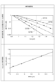
- FIG. 6 is a graph showing the dependence of the cutoff wavelength ⁇ cc and bending loss on the refractive index volume V in the polarization maintaining optical fiber of the present disclosure.
- FIG. 7 is a graph showing the dependence of bending loss and cutoff wavelength of the polarization maintaining optical fiber of the present disclosure on various MFDs at a wavelength of 1.31 ⁇ m.
- FIG. 8 is a graph showing the dependence of the core radius and relative refractive index difference of the polarization-maintaining optical fiber of the present disclosure on various MFDs at a wavelength of 1.31 ⁇ m.
- the polarization-maintaining optical fiber of Patent Document 1 includes a core, a first clad coat, a second clad coat doped with F, a third clad coat, and a pair of stress applying parts.
- each of the pair of stress applying parts is arranged so as to physically divide the second cladding coat.
- a through hole is formed in the center of the F-added rod that will become the second clad coat after drawing, and the rod is made up of a core part and a first clad part that will become the core and first clad coat after drawing.
- the resulting core rod is inserted into the through hole of the F-added rod, and these are further integrated to obtain a first intermediate base material composed of a core portion, a first cladding portion, and a second cladding portion.
- a through hole is formed in the center of the third cladding part as a jacket material that will become the third cladding coat after drawing, and the first intermediate base material is inserted into the through hole of the third cladding part, and further, By integrating these, a second intermediate base material composed of the core portion and the first to third cladding portions is obtained.
- a pair of through-holes are formed at predetermined locations in the second intermediate base material obtained, and a pair of stress-applying rods that will become a pair of stress-applying parts after wire drawing are respectively inserted into the pair of through-holes, and further, By integrating these, an optical fiber preform for obtaining a polarization maintaining optical fiber is obtained.
- the present disclosure has been made in order to solve the above-mentioned problems, and provides a polarization-maintaining optical fiber and its polarization-maintaining optical fiber that has an easy-to-manufacture structure that makes it possible to reduce bending loss when bent to a small radius.
- the purpose is to provide a manufacturing method.
- a polarization-maintaining optical fiber can be obtained that has a structure that enables reduction of bending loss when bent to a small radius.
- the polarization maintaining optical fiber of the present disclosure includes: (1) A core extending along the fiber axis, a pair of stress applying parts, and one or more low refractive index parts, and surrounding each of the core, the pair of stress applying parts, and one or more low refractive index parts A common cladding.
- a common cladding is disposed between the pair of stress applying parts and the core.
- the pair of stress applying parts are arranged on both sides of the core and apart from the core.
- a common cladding is arranged between each of the plurality of low refractive index parts.
- the plurality of low refractive index parts are arranged apart from each other.
- a common cladding is disposed between the one or more low refractive index portions and the core.
- a common cladding is disposed between the one or more low refractive index parts and the pair of stress applying parts.
- One or more low refractive index sections are arranged around the core and spaced apart from both the core and the pair of stress applying sections.
- the one or more low refractive index parts arranged at intervals around the core and also arranged at intervals from each of the pair of stress applying parts serve as a trench layer arranged around the core. Function.
- the polarization-maintaining optical fiber provided with the low refractive index portion achieves a reduction in bending loss when bent to a small radius.
- each low refractive index section does not contact the pair of stress applying sections, complication of element arrangement in the fiber cross section can be avoided, the number of manufacturing steps can be reduced, and manufacturing costs can be reduced.
- each of the one or more low refractive index portions on the cross section of the polarization-maintaining optical fiber is composed of only a straight line, only a curved line, or a combination of a straight line and a curved line. It may have a different shape.
- the outline of each low refractive index portion is composed of all shapes, such as circles, ellipses, quadrangles, and triangles, which are composed of at least one of straight lines and curved lines.
- the polarization maintaining optical fiber may have 2 or more and 6 or less low refractive index parts as one or more low refractive index parts.
- the two to six low refractive index parts are arranged at positions where the center-to-center distances from the center of the core are equal, and so that they do not overlap with either of the pair of stress applying parts. may be placed.
- the cross section of each low refractive index portion is circular, the base material can be manufactured by collapsing a common clad rod inserted into a through hole with a cylindrical low refractive index rod. Therefore, the polarization maintaining optical fiber of the present disclosure can be manufactured at low cost.
- the low refractive index rod is a member that becomes a low refractive index section after drawing
- the common cladding rod is a member that becomes a common cladding after drawing.
- each of the pair of stress applying portions may have an outer diameter of 30 ⁇ m or more and 40 ⁇ m or less on the cross section of the polarization maintaining optical fiber.
- the relative refractive index difference between each of the pair of stress applying parts with respect to the common cladding may be 0.0% or less. That is, the refractive index of each of the pair of stress applying parts may be lower than or equal to the refractive index of the common cladding.
- the ratio a/b_SAP hereinafter referred to as "Ra_SAP" of the radius a of the core to the shortest distance b_SAP from the center of the core to the contour of each of the pair of stress applying parts is 0.4 or more and 0.6 or less.
- each stress-applying portion When the outer diameter of each stress-applying portion is less than 30 ⁇ m or larger than 40 ⁇ m, birefringence in the core becomes small and polarization maintaining characteristics deteriorate. Furthermore, when Ra_SAP is less than 0.4 and the shortest distance from the center of the core to the contour of each stress applying portion is large, the birefringence in the core similarly decreases. On the other hand, if Ra_SAP is larger than 0.6, the through-hole for inserting the stress-applying rod provided in the common clad rod that should become the common clad during base material manufacturing is close to the through-hole for inserting the core rod, making it difficult to manufacture. become.
- the stress applying rod is a member that becomes one of a pair of stress applying parts after wire drawing
- the core rod is a member that becomes a core after wire drawing.
- each stress applying part also contributes to reducing bending loss
- the polarization maintaining optical fiber is arranged so that the center of each stress applying part is in the 0 degree direction, that is, each stress applying part is parallel to the bending plane.
- the bending plane is a plane for indicating the bending direction of the polarization-maintaining optical fiber, and includes the central axis of the polarization-maintaining optical fiber in the bent state.
- the total area of one or more low refractive index parts on the cross section of the polarization maintaining optical fiber and the total area of the one or more low refractive index parts may be 20 ⁇ m 2 ⁇ % or more and 120 ⁇ m 2 ⁇ % or less.
- the polarization maintaining optical fiber has an MFD of 8.2 ⁇ m or more and 10.2 ⁇ m or less at a wavelength of 1.31 ⁇ m and a MFD of 0.15 dB at a wavelength of 1.55 ⁇ m. and a cutoff wavelength of less than 1.26 ⁇ m.
- the bending loss is measured with the polarization maintaining optical fiber being bent once with a bending radius of 5 mm so that each of the pair of stress applying parts is parallel to the bending plane.
- the refractive index volume V is less than 20 ⁇ m 2 ⁇ %, the bending resistance is low, and the bending loss at a wavelength of 1.55 ⁇ m exceeds 0.15 dB.
- the refractive index volume V exceeds 120 ⁇ m 2. %, the spacing between the low refractive index parts when six low refractive index parts are arranged is narrow, making it difficult to form through holes in the base material manufacturing process. .
- the cutoff wavelength and bending loss there is a trade-off relationship between the cutoff wavelength and bending loss, and the ITU-T standard G. 657.
- the allowable width (tolerance) of the structure satisfying B3 depends on the MFD.
- the core may have a radius of 3 ⁇ m or more and 5 ⁇ m or less on the cross section of the polarization maintaining optical fiber, and the core with respect to the common cladding
- the relative refractive index difference may be 0.2% or more and 0.5% or less.
- the relative refractive index difference of one or more low refractive index parts with respect to the common cladding may be -1.0% or more and -0.5% or less.
- the method for manufacturing a polarization-maintaining optical fiber of the present disclosure includes: (8) Producing the polarization-maintaining optical fiber according to any one of (1) to (7) above.
- the manufacturing method includes a base material manufacturing step of manufacturing an optical fiber preform to obtain the polarization maintaining optical fiber, and a drawing step of drawing the optical fiber preform manufactured by the preform manufacturing step. and.
- the base material manufacturing process includes a first sub-process to a fourth sub-process. In the first sub-step, a common cladding rod is prepared which is to become part of the common cladding after drawing.
- preparation of a core rod including a portion to become a core after drawing preparation of one or more low refractive index rods to become one or more low refractive index parts after drawing, and applying a pair of stresses after drawing.
- the preparation of a pair of stress-applying rods to become a part is carried out separately. That is, the second sub-step for the core rod, the second sub-step for the one or more low refractive index rods, and the second sub-step for the pair of stress-applying rods do not need to be performed in parallel. do not have.
- the third sub-step forming a first through hole into which the core rod is inserted, and forming one or more second through holes into which the one or more low refractive index rods are individually inserted, in the common clad rod. , and a pair of third through-holes into which the pair of stress applying rods are individually inserted are individually performed. That is, the third sub-step for the first through-hole, the third sub-step for the second through-hole, and the third sub-step for the third through-hole do not need to be performed in parallel.
- the integration of the common cladding rod and the core rod, the integration of the common cladding rod and one or more low refractive index rods, and the integration of the common cladding rod and the pair of stress applying rods are individually performed. . That is, the fourth sub-process for integrating the core rod, the fourth sub-process for integrating the low refractive index rod, and the fourth sub-process for integrating the stress applying rod do not need to be performed simultaneously. do not have.
- FIG. 1 is a diagram for explaining the structure of the polarization-maintaining optical fiber of the present disclosure (denoted as "fiber structure” in FIG. 1).
- fiber structure in FIG. 1
- cross-sectional structure in FIG. 1
- the second row of FIG. 1 shows the refractive index profile along line L1 in the cross section of the polarization-maintaining optical fiber 10 in the top row. has been done.
- the third row of FIG. 1 (indicated as "refractive index profile (on line L2)" in FIG.
- FIG. 1 shows the refractive index profile along line L2 in the cross section of the polarization-maintaining optical fiber 10 in the top row. has been done.
- the bottom row of FIG. 1 shows the refractive index profile along line L3 in the cross section of the polarization-maintaining optical fiber 10 at the top row. ing.
- the polarization-maintaining optical fiber 10 of the present disclosure includes a glass optical fiber 20 mainly composed of silica glass, and a resin provided on the outer peripheral surface of the glass optical fiber 20.
- a covering 30 is provided.
- the glass optical fiber 20 includes a core 40 extending along the fiber axis AX, a common cladding 50, and a pair of stress applying portions 60A and 60B arranged to sandwich the core 40 at a distance from the core 40. It includes one or more low refractive index parts 70A that surround the core 40 and are spaced apart from both the core 40 and the pair of stress applying parts 60A and 60B.
- each of the pair of stress applying parts 60A and 60B has an outer diameter of 30 ⁇ m or more and 40 ⁇ m or less.
- the relative refractive index difference between the pair of stress applying parts 60A and 60B with respect to the common cladding 50 is 0.0% or less. Note that each of the pair of stress applying portions 60A and 60B may have a positive relative refractive index difference with respect to the common cladding 50, as indicated by the broken line.
- the refractive index profile shown in the third row of FIG. It is given by the relative refractive index difference to each part along the line L2 passing through the center of .
- the relative refractive index difference of each low refractive index portion 70A with respect to the common cladding 50 is ⁇ 1.0% or more and ⁇ 0.5% or less.
- the one or more low refractive index portions 70A surrounding the core 40 function as a trench layer in the entire low refractive index portion 70A.
- the polarization-maintaining optical fiber 10 provided with one or more low refractive index portions 70A achieves a reduction in bending loss when bent to a small radius.
- the refractive index profile shown in the bottom row of FIG. 1 shows two low refractive index parts adjacent to the center of the core 40 in the cross section of the polarization-maintaining optical fiber 10, as shown in the top row of FIG.
- the relative refractive index difference is given to each part along the line L3 passing through the intermediate position of 70A.
- each of the core 40, the pair of stress applying parts 60A, 60B, and the one or more low refractive index parts 70A is connected to the common cladding 50. They are located at physically separate locations with some parts in between. Therefore, as shown from the second row to the bottom row of FIG. It has a different shape when rotated in the direction. Furthermore, since each low refractive index portion 70A is not in contact with the pair of stress applying portions 60A and 60B, complication of the element arrangement in the cross section is avoided, reducing the number of manufacturing steps and making it possible to reduce manufacturing costs. .
- the polarization-maintaining optical fiber 10 having the above-described structure, by providing the low refractive index portions, the refractive index of each low refractive index portion 70A and , the difference between the effective refractive index obtained at the outer edge of the MFD and the effective refractive index obtained at the outer edge of the MFD becomes large, and bending loss when bent to a small radius is reduced compared to a polarization-maintaining optical fiber that does not have a low refractive index section. Can be done.
- MFD, bending loss, and cutoff wavelength are determined according to ITU-T standard G. 657. It becomes easy to design to satisfy B3. If the diameter of the core 40, the position and size of each low refractive index portion 70A and the pair of stress applying portions 60A and 60B are appropriately selected, the ITU-T standard G. 657. It becomes possible to lower manufacturing costs while complying with B3.
- FIG. 2 is a diagram showing various arrangement patterns of low refractive index portions on a cross section of the polarization-maintaining optical fiber of the present disclosure (in FIG. 2, it is written as “arrangement pattern of low refractive index portions”). Note that patterns A to H shown in FIG. 2 are all arrangement patterns on the cross section of the glass optical fiber 20 orthogonal to the fiber axis AX.
- the contour of each low refractive index portion may have a shape consisting of only a straight line, only a curved line, or a combination of a straight line and a curved line.
- the cross-sectional shape of the low refractive index portion applied to the polarization-maintaining optical fiber 10 of the present disclosure defined by the contour on the cross-section of the polarization-maintaining optical fiber 10 is as illustrated in FIG. There is no limit to the shape defined by the contour as long as it is not in contact with a stress-applying part.
- each group of low refractive index portions is composed of three low refractive index portions 70A each having a circular outline.
- pattern B shown in FIG. 2 also has two groups of low refractive index portions arranged.
- each group of low refractive index portions is composed of two low refractive index portions 70B each having a circular outline.
- Pattern C shown in FIG. 2 also has two groups of low refractive index portions arranged, similar to the above-described patterns A and B.
- each group of low refractive index portions is composed of one low refractive index portion 70C having a circular outline.
- pattern D shown in FIG. 2 has two groups of low refractive index portions arranged, but the outline shape of each low refractive index portion 70D is non-circular. That is, each group of low refractive index portions is composed of three low refractive index portions 70D each having an elliptical outline. Further, each of the two groups of low refractive index portions of pattern E shown in FIG. 2 is composed of three low refractive index portions 70E. The outline shape of each low refractive index portion 70E is rectangular. Each of the two low refractive index section groups of pattern F shown in FIG. 2 is constituted by one low refractive index section 70F. The outline shape of each low refractive index portion 70F is triangular.
- Each of the two groups of low refractive index portions of pattern G shown in FIG. 2 is constituted by one low refractive index portion 70G.
- the outline shape of each low refractive index portion 70G is trapezoidal.
- each of the two low refractive index section groups of pattern H shown in FIG. 2 is composed of two low refractive index sections 70H.
- the outline shape of each low refractive index portion 70H is star-shaped.
- FIG. 3 is a diagram for explaining the arrangement conditions of the low refractive index portion on the cross section of the polarization maintaining optical fiber 10 of the present disclosure.
- the low refractive index portion 70A of pattern A shown in FIG. 2 will be described as a representative example of the low refractive index portion.
- the arrangement of the core 40, each low refractive index section 70A, and the pair of stress applying sections 60A and 60B is as follows. It is defined by an orthogonal coordinate system (xy coordinate system) with the origin at the center of . Note that in FIG. 3, the x-axis coincides with the line L1 shown at the top of FIG. 1, and the y-axis coincides with the line L2.
- the radius of the core 40 is a.
- the shortest distance from the center of the core 40 to the outline of each low refractive index portion 70A is b_A.
- the longest distance from the center of the core 40 to the contour of each low refractive index portion 70A is c_A.
- the shortest distance from the center of the core 40 to the contours of each of the pair of stress applying parts 60A and 60B is b_SAP.
- each of the pair of stress applying portions 60A and 60B is less than 30 ⁇ m or larger than 40 ⁇ m, birefringence in the core 40 becomes small and polarization maintaining characteristics deteriorate.
- Ra_SAP is less than 0.4 and the shortest distance from the center of the core 40 to the contours of the pair of stress applying parts 60A and 60B is large, the birefringence in the core 40 is similarly reduced.
- Ra_SAP is larger than 0.6, the through-hole for inserting the stress applying rod provided in the common clad rod which is to become the common clad 50 during the manufacture of the base material and the through-hole for inserting the core rod become close to each other, resulting in a manufacturing problem.
- the stress applying rod is a member that becomes either the stress applying portion 60A or 60B after wire drawing
- the core rod is a member that becomes the core 40 after wire drawing.
- the pair of stress applying parts 60A and 60B also contribute to reducing bending loss. In particular, when the polarization maintaining optical fiber 10 is bent so that the centers of the pair of stress applying parts 60A and 60B are in the 0 degree direction, that is, each of the pair of stress applying parts 60A and 60B is parallel to the bending plane.
- the line L1 passing through the center of the pair of stress applying parts 60A and 60B at each location along the longitudinal direction of the polarization-maintaining optical fiber 10 is perpendicular to the bending plane, and at this time, the bending loss is greatly reduced.
- the polarization maintaining optical fiber 10 of the present disclosure complies with ITU-T standard G. 657.
- two or more and six or less low refractive index parts are provided, such as the low refractive index parts 70A to 70H shown in FIG.
- the two to six low refractive index parts on the cross section are arranged at positions where the center-to-center distances from the center of the core 40 are the same, and both of the pair of stress applying parts 60A and 60B are arranged. They are arranged so that they do not overlap. Note that when the cross-sectional shape of each of the low refractive index portions 70A to 70C is circular, the polarization-maintaining optical fiber 10 can be manufactured at low cost.
- the optical fiber preform manufacturing costs associated with forming through holes in the common clad rod that will become the common clad 50 after drawing are reduced.
- the number of low refractive index portions is small, confinement of the fundamental mode becomes weaker, which becomes a factor in increasing bending loss. Therefore, according to the polarization-maintaining optical fiber 10 of the present disclosure, it is important to adjust the number of low refractive index portions so that the desired cutoff wavelength and bending loss characteristics can be obtained.
- FIG. 4 is a diagram for explaining a method for manufacturing an optical fiber preform 100C for obtaining the polarization-maintaining optical fiber 10 of the present disclosure (denoted as "preform production” in FIG. 4).
- FIG. 5 is a diagram showing the configuration of a drawing apparatus for obtaining the polarization-maintaining optical fiber 10 of the present disclosure.
- step ST1 in FIG. 4
- Step ST2 The middle part of FIG. 4 (denoted as "Step ST2" in FIG.
- Step ST3 shows a light beam in which member preparation, hole opening, insertion, and sintering are performed to obtain the optical fiber preform 100C from the intermediate preform 100B.
- the fiber preform manufacturing process is shown.
- the low refractive index portion 70A of pattern A shown in FIG. 2 will be described as a representative example of the low refractive index portion.
- the method for manufacturing the polarization-maintaining optical fiber 10 of the present disclosure includes a base material manufacturing process illustrated in FIG. 4 and a wire drawing process illustrated in FIG. 5.
- the preform manufacturing process includes a first sub-process to a fourth sub-process in order to obtain the optical fiber preform 100C.
- a common clad rod 100A is prepared.
- the common clad rod 100A is processed so as to leave a clad outer portion 403 that will become the physical clad layer of the common clad 50 after drawing. This physical cladding layer is called a jacket layer.
- the core rod 400A includes a core portion 401 that will become the core 40 after drawing in the center of the pure silica rod, and is constituted by the core portion 401 and a clad inner portion 402 surrounding the core portion 401.
- the inner cladding portion 402 is a portion that becomes the optical cladding layer of the common cladding 50 after drawing.
- One or more low refractive index rods 700A are members that should become one or more low refractive index parts 70A after drawing.
- the pair of stress applying rods 600A and 600B are members that are to become a pair of stress applying parts 60A and 60B after wire drawing. Note that the second sub-process for the core rod 400A, the second sub-process for one or more low refractive index rods 700A, and the second sub-process for the pair of stress applying rods 600A and 600B are performed in parallel. It does not need to be implemented.
- the third sub-step forming a first through hole 400B into which the core rod 400A is inserted, and forming one or more second through holes into which one or more low refractive index rods 700A are individually inserted into the common clad rod 100A.
- the formation of the through hole 700B and the formation of the pair of third through holes 610A, 610B into which the pair of stress applying rods 600A, 600B are individually inserted are performed individually.
- the common clad rod 100A in which the first through hole 400B is formed corresponds to the clad outer portion 403.
- the third sub-step for the first through-hole 400B, the third sub-step for the second through-hole 700B, and the third sub-step for the third through-holes 610A and 610B do not need to be performed simultaneously. do not have.
- the common clad rod 100A and the core rod 400A are integrated, the common clad rod 100A is integrated with one or more low refractive index rods 700A, and the common clad rod 100A and the pair of stress applying rods 600A, 600B are integrated. Integration is performed separately.
- the fourth sub-step for integrating the core rod, the fourth sub-step for integrating the low refractive index rod, and the fourth sub-step for integrating the stress applying rod do not need to be performed simultaneously. Note that the common clad rod 100A and the core rod 400A are integrated into one body by collapsing the common clad rod 100A while the core rod 400A is inserted into the first through hole 400B.
- the clad inner part 402 of the core rod 400A and the clad outer part 403 of the common clad rod 100A constitute a part that will become the common clad 50 after drawing.
- the common clad rod 100A and one or more low refractive index rods 700A are integrated by inserting one or more low refractive index rods 700A into one or more second through holes 700B, and then inserting the common clad rod 100A into one or more low refractive index rods 700A. This is achieved by collapsing.
- the common clad rod 100A and the pair of stress applying rods 600A, 600B are produced by collapsing the common clad rod 100A with the pair of stress applying rods 600A, 600B inserted into the pair of third through holes 610A, 610B. Realized.
- the second to fourth sub-steps for the core rod 400A, the second to fourth sub-steps for the low refractive index rod 700A, and a pair of stress application steps are performed.
- the second to fourth sub-steps for the rods 600A and 600B may be performed in order.
- the second to fourth sub-processes for the core rod 400A are performed, and then the low refractive index rod 700A and the pair of stress-applying
- the second to fourth sub-steps are performed for both rods 600A and 600B.
- step ST1 shown in the upper part of FIG. 4 a first sub-process for the common clad rod 100A and a second sub-process for the core rod 400A are performed. That is, in step ST1, a common clad rod 100A and a core rod 400A composed of a core part 401 and a clad inner part 402 are prepared. Subsequently, in step ST2 shown in the middle part of FIG. 4, a third sub-step and a fourth sub-step for the core rod 400A are performed, and finally an intermediate base material 100B is obtained.
- This intermediate base material 100B is a common clad rod 100A into which a core rod 400A is integrated, and is composed of a clad inner part 402 and a clad outer part 403 after the third sub-step.
- step ST3 shown in the lower part of FIG. 4 one or more low refractive index rods 700A and a pair of stress applying rods 600A and 600B are further prepared as a second sub-step. Subsequently, the third sub-step and fourth sub-step for one or more low refractive index rods 700A and the third sub-step and fourth sub-step for the pair of stress applying rods 600A and 600B are performed in parallel.
- the optical fiber preform 100C is finally obtained.
- This optical fiber preform 100C is a common clad rod 100A in which, in addition to the core rod 400A, one or more low refractive index rods 700A and a pair of stress applying rods 600A and 600B are integrated.
- each of the core rod 400A, one or more low refractive index rods 700A, and the pair of stress applying rods 600A and 600B are each A common clad rod 100A is arranged between them.
- the optical fiber preform 100C manufactured as described above is set in the drawing apparatus shown in FIG. 5 to obtain the polarization-maintaining optical fiber 10 of the present disclosure.
- the wire drawing device includes a heater 200, a resin coating device 300, a roller 410, and a winding device 420.
- the winding device 420 rotates in the direction indicated by the arrow S, the glass optical fiber is pulled out from one end of the optical fiber preform 100C heated by the heater 200.
- This glass optical fiber is coated with resin on its outer peripheral surface by a resin coating device 300, and finally, the polarization maintaining optical fiber 10 coated with resin is transferred to a drum of a winding device 420 via a roller 410. It is wound up.
- the cross-sectional structure of the polarization-maintaining optical fiber 10 along line II shown in FIG. 5 corresponds to the cross-sectional structure shown in the upper part of FIG.
- FIG. 6 is a graph showing the dependence of the cutoff wavelength ⁇ cc and bending loss on the refractive index volume V in the polarization maintaining optical fiber of the present disclosure.
- FIG. 7 is a graph showing the dependence of the bending loss and cutoff wavelength of the polarization-maintaining optical fiber of the present disclosure on various MFDs at a wavelength of 1.31 ⁇ m (denoted as “MFD dependence” in FIG. 7). .
- MFD dependence 1.31 ⁇ m
- FIG. 7 (denoted as "bending loss- ⁇ cc characteristics when changing MFD” in FIG. 7), changes in bending loss with respect to ⁇ cc are shown for various MFDs.
- the lower part of FIG. 7 (denoted as “ ⁇ cc_min-MFD characteristics" in FIG. 7) shows the change in the cutoff wavelength ⁇ cc_min for the MFD at a wavelength of 1.31 ⁇ m.
- FIG. 8 is a graph showing the dependence of the core radius and relative refractive index difference on the MFD of the polarization maintaining optical fiber of the present disclosure.
- the horizontal axis is the refractive index volume V ( ⁇ m 2 ⁇ %).
- This refractive index volume V is the total cross-sectional area of the six low refractive index parts 70A shown as pattern A among the various low refractive index parts 70A to 70H shown in FIG. This is the product of the absolute value of the average relative refractive index difference of the refractive index portion 70A.
- the relative refractive index difference of each low refractive index section 70A with respect to the common cladding 50 is set to -1.0% or more and -0.5% or less.
- the upper part of the vertical axis is the cutoff wavelength ⁇ cc ( ⁇ m).
- the lower part of the vertical axis is the bending loss (dB).
- This bending loss was measured by inputting light with a wavelength of 1.55 ⁇ m while the polarization-maintaining optical fiber to be measured was bent once with a bending radius of 5 mm so that each of the pair of stress applying parts was parallel to the bending plane. Transmission loss is sometimes measured.
- the bending loss at the cutoff wavelength ⁇ cc and the wavelength of 1.55 ⁇ m shows dependence on the refractive index volume V.
- Each low refractive index portion 70A functions as a trench layer and thus contributes to reducing bending loss.
- the refractive index volume V should be 20 ⁇ m 2 ⁇ % or more.
- the refractive index volume V exceeds 120 ⁇ m 2.
- the refractive index volume V exceeds 120 ⁇ m 2. % The following is sufficient. In this way, by appropriately selecting the refractive index volume V, the ITU-T standard G. 657. A polarization-maintaining optical fiber 10 compliant with B3 is obtained.
- the horizontal axis is the cutoff wavelength ⁇ cc (dB).
- the vertical axis is the same bending loss (dB) as in the lower part of the vertical axis in FIG.
- graph G710 shows the bending loss- ⁇ cc characteristic of a sample with an MFD of 10.2 ⁇ m at a wavelength of 1.31 ⁇ m.
- Graph G720 shows the bending loss- ⁇ cc characteristic when the MFD is 9.6 ⁇ m.
- Graph G730 shows the bending loss- ⁇ cc characteristic of the sample whose MFD is 8.8 ⁇ m.
- Graph G740 shows the bending loss- ⁇ cc characteristic of the sample whose MFD is 8.2 ⁇ m.
- the horizontal axis is the MFD ( ⁇ m) at a wavelength of 1.31 ⁇ m.
- the vertical axis is the cutoff wavelength ⁇ cc_min ( ⁇ m) when the bending loss at a wavelength of 1.55 ⁇ m is 0.15 dB.
- the bending loss at the cutoff wavelength ⁇ cc and the wavelength of 1.55 ⁇ m shows dependence on the MFD at the wavelength of 1.31 ⁇ m. That is, the smaller the MFD, the stronger the light confinement and the greater the tolerance, so the smaller the MFD, the greater the tolerance.
- the MCF is 8.2 ⁇ m or more and 10.2 ⁇ m or less
- the bending loss is less than 0.15 dB at a wavelength of 1.55 ⁇ m and the cutoff wavelength is less than 1.26 ⁇ m. It is possible to realize ⁇ cc.
- the horizontal axis is the relative refractive index difference of the core 40 with respect to the common cladding 50 (denoted as "core ⁇ " in FIG. 8).
- the vertical axis is the radius a of the core 40.
- graph G810 shows the relationship between core ⁇ and core radius when the MFD is 7 ⁇ m at a wavelength of 1.31 ⁇ m.
- Graph G820 shows the relationship between core ⁇ and core radius when the MFD is 8 ⁇ m.
- Graph G830 shows the relationship between core ⁇ and core radius when the MFD is 9 ⁇ m.
- Graph G840 shows the relationship between core ⁇ and core radius when the MFD is 10 ⁇ m.
- Graph G850 shows the relationship between core ⁇ and core radius when the MFD is 11 ⁇ m.
- Graph G860 shows the relationship between core ⁇ and core radius when the MFD is 12 ⁇ m.
- Graph G870 shows the relationship between core ⁇ and core radius when the MFD is 13 ⁇ m.
- the radius of core 40 on the cross section of polarization-maintaining optical fiber 10 is It is sufficient if the thickness falls within the range of 3 ⁇ m or more and 5 ⁇ m or less. Further, the relative refractive index difference between the core 40 and the common cladding 50 may be within a range of 0.2% or more and 0.5% or less.
- a core extending along the fiber axis; a pair of stress applying parts; one or more low refractive index portions; a common cladding surrounding the core, the pair of stress applying parts, and the one or more low refractive index parts;
- a polarization-maintaining optical fiber comprising: On a cross section of the polarization maintaining optical fiber perpendicular to the fiber axis, The pair of stress applying parts are arranged on both sides of the core in a state separated from the core with a part of the common cladding in between, The one or more low refractive index parts are separated from each other with a part of the common cladding in between, and are separated from both the core and the pair of stress applying parts with a part of the common cladding in between.
- a second sub-step of separately preparing a pair of stress-applying rods to be used Forming a first through hole into which the core rod is inserted into the common clad rod; forming one or more second through holes into which the one or more low refractive index rods are individually inserted; and a third sub-step of individually forming a pair of third through holes into which the pair of stress applying rods are individually inserted, a step of individually performing the integration of the common cladding rod and the core rod, the integration of the common cladding rod and the one or more low refractive index rods, and the integration of the common cladding and the pair of stress applying rods; four sub-processes, including; In the optical fiber preform, the core rod, each of the one or more low refractive index rods, and each of the pair of stress applying rods are physically separated with a part of the common cladding rod in between. located in the state, A method for manufacturing polarization-maintaining optical fiber.
Landscapes
- Physics & Mathematics (AREA)
- Engineering & Computer Science (AREA)
- Chemical & Material Sciences (AREA)
- General Physics & Mathematics (AREA)
- Optics & Photonics (AREA)
- Life Sciences & Earth Sciences (AREA)
- General Life Sciences & Earth Sciences (AREA)
- Geochemistry & Mineralogy (AREA)
- Manufacturing & Machinery (AREA)
- Materials Engineering (AREA)
- Organic Chemistry (AREA)
- Optical Fibers, Optical Fiber Cores, And Optical Fiber Bundles (AREA)
Priority Applications (2)
| Application Number | Priority Date | Filing Date | Title |
|---|---|---|---|
| CN202380062141.3A CN119768717A (zh) | 2022-09-07 | 2023-07-14 | 偏振保持光纤及偏振保持光纤的制造方法 |
| JP2024545477A JPWO2024053252A1 (https=) | 2022-09-07 | 2023-07-14 |
Applications Claiming Priority (2)
| Application Number | Priority Date | Filing Date | Title |
|---|---|---|---|
| JP2022142279 | 2022-09-07 | ||
| JP2022-142279 | 2022-09-07 |
Publications (1)
| Publication Number | Publication Date |
|---|---|
| WO2024053252A1 true WO2024053252A1 (ja) | 2024-03-14 |
Family
ID=90192430
Family Applications (1)
| Application Number | Title | Priority Date | Filing Date |
|---|---|---|---|
| PCT/JP2023/026095 Ceased WO2024053252A1 (ja) | 2022-09-07 | 2023-07-14 | 偏波保持光ファイバおよび偏波保持光ファイバの製造方法 |
Country Status (4)
| Country | Link |
|---|---|
| JP (1) | JPWO2024053252A1 (https=) |
| CN (1) | CN119768717A (https=) |
| TW (1) | TW202434925A (https=) |
| WO (1) | WO2024053252A1 (https=) |
Cited By (1)
| Publication number | Priority date | Publication date | Assignee | Title |
|---|---|---|---|---|
| WO2025159182A1 (ja) * | 2024-01-26 | 2025-07-31 | 株式会社フジクラ | 偏波保持ファイバ |
Citations (9)
| Publication number | Priority date | Publication date | Assignee | Title |
|---|---|---|---|---|
| JPS636507A (ja) * | 1986-06-27 | 1988-01-12 | Sumitomo Electric Ind Ltd | 定偏波光フアイバ |
| US20060291789A1 (en) * | 2003-12-19 | 2006-12-28 | Crystal Fibre A/S | Photonic crystal fibres comprising stress elements |
| JP2007108642A (ja) * | 2005-10-11 | 2007-04-26 | Furukawa Electric Co Ltd:The | 光ファイバおよび光伝送媒体 |
| WO2008126472A1 (ja) * | 2007-04-06 | 2008-10-23 | Fujikura Ltd. | フォトニックバンドギャップファイバ及びファイバ増幅器 |
| JP2011503636A (ja) * | 2007-07-31 | 2011-01-27 | コーニング インコーポレイテッド | 偏波維持光ファイバおよび単一偏波光ファイバ |
| JP2011170061A (ja) * | 2010-02-18 | 2011-09-01 | Nippon Telegr & Teleph Corp <Ntt> | 光ファイバおよび光ファイバの製造方法 |
| WO2012046696A1 (ja) * | 2010-10-05 | 2012-04-12 | 株式会社フジクラ | 偏波保持光ファイバ |
| JP2015184371A (ja) * | 2014-03-20 | 2015-10-22 | 株式会社フジクラ | 偏波保持光ファイバ |
| JP2017503189A (ja) * | 2013-11-22 | 2017-01-26 | イムラ アメリカ インコーポレイテッド | 偏光及び偏波保持漏洩チャネルファイバ |
-
2023
- 2023-07-14 JP JP2024545477A patent/JPWO2024053252A1/ja active Pending
- 2023-07-14 CN CN202380062141.3A patent/CN119768717A/zh active Pending
- 2023-07-14 WO PCT/JP2023/026095 patent/WO2024053252A1/ja not_active Ceased
- 2023-08-31 TW TW112132987A patent/TW202434925A/zh unknown
Patent Citations (9)
| Publication number | Priority date | Publication date | Assignee | Title |
|---|---|---|---|---|
| JPS636507A (ja) * | 1986-06-27 | 1988-01-12 | Sumitomo Electric Ind Ltd | 定偏波光フアイバ |
| US20060291789A1 (en) * | 2003-12-19 | 2006-12-28 | Crystal Fibre A/S | Photonic crystal fibres comprising stress elements |
| JP2007108642A (ja) * | 2005-10-11 | 2007-04-26 | Furukawa Electric Co Ltd:The | 光ファイバおよび光伝送媒体 |
| WO2008126472A1 (ja) * | 2007-04-06 | 2008-10-23 | Fujikura Ltd. | フォトニックバンドギャップファイバ及びファイバ増幅器 |
| JP2011503636A (ja) * | 2007-07-31 | 2011-01-27 | コーニング インコーポレイテッド | 偏波維持光ファイバおよび単一偏波光ファイバ |
| JP2011170061A (ja) * | 2010-02-18 | 2011-09-01 | Nippon Telegr & Teleph Corp <Ntt> | 光ファイバおよび光ファイバの製造方法 |
| WO2012046696A1 (ja) * | 2010-10-05 | 2012-04-12 | 株式会社フジクラ | 偏波保持光ファイバ |
| JP2017503189A (ja) * | 2013-11-22 | 2017-01-26 | イムラ アメリカ インコーポレイテッド | 偏光及び偏波保持漏洩チャネルファイバ |
| JP2015184371A (ja) * | 2014-03-20 | 2015-10-22 | 株式会社フジクラ | 偏波保持光ファイバ |
Cited By (1)
| Publication number | Priority date | Publication date | Assignee | Title |
|---|---|---|---|---|
| WO2025159182A1 (ja) * | 2024-01-26 | 2025-07-31 | 株式会社フジクラ | 偏波保持ファイバ |
Also Published As
| Publication number | Publication date |
|---|---|
| TW202434925A (zh) | 2024-09-01 |
| CN119768717A (zh) | 2025-04-04 |
| JPWO2024053252A1 (https=) | 2024-03-14 |
Similar Documents
| Publication | Publication Date | Title |
|---|---|---|
| JP5684109B2 (ja) | マルチコア光ファイバ | |
| JP5224371B2 (ja) | マルチコア光ファイバ | |
| JP5409928B2 (ja) | 偏波保持光ファイバ | |
| JPWO2011114795A1 (ja) | マルチコア光ファイバおよびその製造方法 | |
| CN115136046A (zh) | 多芯光纤、多芯光纤带、多芯光纤的制造方法及处理方法 | |
| GB2205828A (en) | Methods of manufacturing polarisation-maintaining optical fibres | |
| CN116171396A (zh) | 多芯光纤及设计方法 | |
| JP7335817B2 (ja) | マルチコアファイバ及びその製造方法 | |
| US20250004192A1 (en) | Anti-resonant hollow-core fibers featuring support structures | |
| KR20180124729A (ko) | 광파이버 | |
| WO2024053252A1 (ja) | 偏波保持光ファイバおよび偏波保持光ファイバの製造方法 | |
| JP6010519B2 (ja) | マルチコアファイバ | |
| CN103176246A (zh) | 包含连接器的多芯光纤 | |
| CN114641715A (zh) | 光连接器件 | |
| JP7400585B2 (ja) | マルチコアファイバの母材の製造方法及びマルチコアファイバの製造方法 | |
| US20250110269A1 (en) | Anti-resonant hollow-core fibers featuring support structures | |
| JPH07187696A (ja) | 光ファイバ用母材の製造方法 | |
| JP2002524766A (ja) | 半径方向及び方位角方向に非対称なコアを有するシングルモード光導波路ファイバ | |
| JP2009008850A (ja) | デュアルガイド光ファイバ | |
| JP2015121642A (ja) | マルチコアファイバの製造方法 | |
| JPWO2024053252A5 (https=) | ||
| JP7060532B2 (ja) | 光ファイバおよび光ファイバの製造方法 | |
| JP2016075918A (ja) | 光ファイバ、及び光ファイバを製造する方法 | |
| JP2022020908A (ja) | マルチコアファイバおよびその製造方法、ケーブル、ならびに通信システム | |
| WO2025253768A1 (ja) | マルチコア光ファイバの製造方法 |
Legal Events
| Date | Code | Title | Description |
|---|---|---|---|
| 121 | Ep: the epo has been informed by wipo that ep was designated in this application |
Ref document number: 23862796 Country of ref document: EP Kind code of ref document: A1 |
|
| WWE | Wipo information: entry into national phase |
Ref document number: 2024545477 Country of ref document: JP |
|
| WWE | Wipo information: entry into national phase |
Ref document number: 202380062141.3 Country of ref document: CN |
|
| WWP | Wipo information: published in national office |
Ref document number: 202380062141.3 Country of ref document: CN |
|
| NENP | Non-entry into the national phase |
Ref country code: DE |
|
| 122 | Ep: pct application non-entry in european phase |
Ref document number: 23862796 Country of ref document: EP Kind code of ref document: A1 |