WO2024053252A1 - Polarization maintaining optical fiber and method for manufacturing polarization maintaining optical fiber - Google Patents
Polarization maintaining optical fiber and method for manufacturing polarization maintaining optical fiber Download PDFInfo
- Publication number
- WO2024053252A1 WO2024053252A1 PCT/JP2023/026095 JP2023026095W WO2024053252A1 WO 2024053252 A1 WO2024053252 A1 WO 2024053252A1 JP 2023026095 W JP2023026095 W JP 2023026095W WO 2024053252 A1 WO2024053252 A1 WO 2024053252A1
- Authority
- WO
- WIPO (PCT)
- Prior art keywords
- refractive index
- core
- optical fiber
- low refractive
- pair
- Prior art date
Links
- 239000013307 optical fiber Substances 0.000 title claims abstract description 142
- 238000004519 manufacturing process Methods 0.000 title claims abstract description 58
- 230000010287 polarization Effects 0.000 title claims abstract description 46
- 238000000034 method Methods 0.000 title claims description 28
- 238000005253 cladding Methods 0.000 claims abstract description 68
- 238000005452 bending Methods 0.000 claims abstract description 62
- 239000000835 fiber Substances 0.000 claims abstract description 14
- 239000000463 material Substances 0.000 claims description 26
- 238000002360 preparation method Methods 0.000 claims description 12
- 238000010586 diagram Methods 0.000 description 10
- 230000010354 integration Effects 0.000 description 8
- 238000005491 wire drawing Methods 0.000 description 8
- 239000011521 glass Substances 0.000 description 7
- 239000011347 resin Substances 0.000 description 7
- 229920005989 resin Polymers 0.000 description 7
- 230000003287 optical effect Effects 0.000 description 6
- 239000011248 coating agent Substances 0.000 description 4
- 238000000576 coating method Methods 0.000 description 4
- 238000004804 winding Methods 0.000 description 4
- 230000005540 biological transmission Effects 0.000 description 2
- 230000015572 biosynthetic process Effects 0.000 description 2
- 230000007423 decrease Effects 0.000 description 2
- 238000003780 insertion Methods 0.000 description 2
- 230000037431 insertion Effects 0.000 description 2
- 230000002093 peripheral effect Effects 0.000 description 2
- 238000005245 sintering Methods 0.000 description 2
- PXGOKWXKJXAPGV-UHFFFAOYSA-N Fluorine Chemical compound FF PXGOKWXKJXAPGV-UHFFFAOYSA-N 0.000 description 1
- VYPSYNLAJGMNEJ-UHFFFAOYSA-N Silicium dioxide Chemical compound O=[Si]=O VYPSYNLAJGMNEJ-UHFFFAOYSA-N 0.000 description 1
- 230000003247 decreasing effect Effects 0.000 description 1
- 230000001419 dependent effect Effects 0.000 description 1
- 230000000694 effects Effects 0.000 description 1
- 229910052731 fluorine Inorganic materials 0.000 description 1
- 239000011737 fluorine Substances 0.000 description 1
- 235000012239 silicon dioxide Nutrition 0.000 description 1
Images


Classifications
-
- C—CHEMISTRY; METALLURGY
- C03—GLASS; MINERAL OR SLAG WOOL
- C03B—MANUFACTURE, SHAPING, OR SUPPLEMENTARY PROCESSES
- C03B37/00—Manufacture or treatment of flakes, fibres, or filaments from softened glass, minerals, or slags
- C03B37/01—Manufacture of glass fibres or filaments
- C03B37/012—Manufacture of preforms for drawing fibres or filaments
-
- C—CHEMISTRY; METALLURGY
- C03—GLASS; MINERAL OR SLAG WOOL
- C03B—MANUFACTURE, SHAPING, OR SUPPLEMENTARY PROCESSES
- C03B37/00—Manufacture or treatment of flakes, fibres, or filaments from softened glass, minerals, or slags
- C03B37/01—Manufacture of glass fibres or filaments
- C03B37/02—Manufacture of glass fibres or filaments by drawing or extruding, e.g. direct drawing of molten glass from nozzles; Cooling fins therefor
- C03B37/025—Manufacture of glass fibres or filaments by drawing or extruding, e.g. direct drawing of molten glass from nozzles; Cooling fins therefor from reheated softened tubes, rods, fibres or filaments, e.g. drawing fibres from preforms
- C03B37/027—Fibres composed of different sorts of glass, e.g. glass optical fibres
-
- G—PHYSICS
- G02—OPTICS
- G02B—OPTICAL ELEMENTS, SYSTEMS OR APPARATUS
- G02B6/00—Light guides; Structural details of arrangements comprising light guides and other optical elements, e.g. couplings
- G02B6/02—Optical fibres with cladding with or without a coating
-
- G—PHYSICS
- G02—OPTICS
- G02B—OPTICAL ELEMENTS, SYSTEMS OR APPARATUS
- G02B6/00—Light guides; Structural details of arrangements comprising light guides and other optical elements, e.g. couplings
- G02B6/02—Optical fibres with cladding with or without a coating
- G02B6/024—Optical fibres with cladding with or without a coating with polarisation maintaining properties
-
- G—PHYSICS
- G02—OPTICS
- G02B—OPTICAL ELEMENTS, SYSTEMS OR APPARATUS
- G02B6/00—Light guides; Structural details of arrangements comprising light guides and other optical elements, e.g. couplings
- G02B6/02—Optical fibres with cladding with or without a coating
- G02B6/036—Optical fibres with cladding with or without a coating core or cladding comprising multiple layers
Definitions
- the present disclosure relates to a polarization-maintaining optical fiber and a method of manufacturing the polarization-maintaining optical fiber.
- Polarization-maintaining optical fibers are used to connect polarization-dependent optical devices in optical transmission and reception systems.
- the polarization-maintaining optical fiber disclosed in Patent Document 1 includes a core, a first clad coat surrounding the core, and a second clad coat with a low refractive index surrounding the first clad coat and functioning as a trench. , a third clad coat surrounding the second clad coat, and a pair of stress applying parts arranged to sandwich the core.
- the radius ratio r2/r1 of the first clad coat and the second clad coat is 2.5 or more and 4.5 or less.
- the refractive index volume V of the second cladding coat is 25 ⁇ m 2 ⁇ % or more and 110 ⁇ m 2 ⁇ % or less.
- the pair of stress applying parts are arranged so as to physically separate the second clad coat.
- a second cladding coat doped with F (fluorine) is provided to function as a trench, so that the refractive index of the second cladding coat and the mode field diameter (hereinafter referred to as "MFD") becomes large. Therefore, the polarization-maintaining optical fiber of Patent Document 1 does not reduce the MFD when bent to a small radius, compared to a polarization-maintaining optical fiber to which a trench corresponding to the second cladding coat is not applied. Bending loss can be reduced.
- the polarization-maintaining optical fiber of the present disclosure includes a core extending along the fiber axis, a pair of stress applying parts, one or more low refractive index parts, a core, a pair of stress applying parts, and one or more low refractive index parts. a common cladding surrounding each of the refractive index sections.
- a common cladding surrounding each of the refractive index sections.
- a common cladding is disposed between the pair of stress applying parts and the core.
- the pair of stress applying parts are arranged on both sides of the core and apart from the core.
- a common cladding is arranged between each of the plurality of low refractive index parts.
- the plurality of low refractive index parts are arranged apart from each other.
- a common cladding is disposed between the one or more low refractive index portions and the core.
- a common cladding is disposed between the one or more low refractive index parts and the pair of stress applying parts.
- One or more low refractive index sections are arranged around the core and spaced apart from both the core and the pair of stress applying sections.
- FIG. 1 is a diagram for explaining the structure of the polarization-maintaining optical fiber of the present disclosure.
- FIG. 2 is a diagram showing various arrangement patterns of low refractive index portions on a cross section of the polarization maintaining optical fiber of the present disclosure.
- FIG. 3 is a diagram for explaining the arrangement conditions of the low refractive index portion on the cross section of the polarization maintaining optical fiber of the present disclosure.
- FIG. 4 is a diagram for explaining a method for manufacturing an optical fiber preform for obtaining a polarization-maintaining optical fiber of the present disclosure.
- FIG. 5 is a diagram showing the configuration of a drawing apparatus for obtaining the polarization-maintaining optical fiber of the present disclosure.
- FIG. 6 is a graph showing the dependence of the cutoff wavelength ⁇ cc and bending loss on the refractive index volume V in the polarization maintaining optical fiber of the present disclosure.
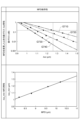
- FIG. 7 is a graph showing the dependence of bending loss and cutoff wavelength of the polarization maintaining optical fiber of the present disclosure on various MFDs at a wavelength of 1.31 ⁇ m.
- FIG. 8 is a graph showing the dependence of the core radius and relative refractive index difference of the polarization-maintaining optical fiber of the present disclosure on various MFDs at a wavelength of 1.31 ⁇ m.
- the polarization-maintaining optical fiber of Patent Document 1 includes a core, a first clad coat, a second clad coat doped with F, a third clad coat, and a pair of stress applying parts.
- each of the pair of stress applying parts is arranged so as to physically divide the second cladding coat.
- a through hole is formed in the center of the F-added rod that will become the second clad coat after drawing, and the rod is made up of a core part and a first clad part that will become the core and first clad coat after drawing.
- the resulting core rod is inserted into the through hole of the F-added rod, and these are further integrated to obtain a first intermediate base material composed of a core portion, a first cladding portion, and a second cladding portion.
- a through hole is formed in the center of the third cladding part as a jacket material that will become the third cladding coat after drawing, and the first intermediate base material is inserted into the through hole of the third cladding part, and further, By integrating these, a second intermediate base material composed of the core portion and the first to third cladding portions is obtained.
- a pair of through-holes are formed at predetermined locations in the second intermediate base material obtained, and a pair of stress-applying rods that will become a pair of stress-applying parts after wire drawing are respectively inserted into the pair of through-holes, and further, By integrating these, an optical fiber preform for obtaining a polarization maintaining optical fiber is obtained.
- the present disclosure has been made in order to solve the above-mentioned problems, and provides a polarization-maintaining optical fiber and its polarization-maintaining optical fiber that has an easy-to-manufacture structure that makes it possible to reduce bending loss when bent to a small radius.
- the purpose is to provide a manufacturing method.
- a polarization-maintaining optical fiber can be obtained that has a structure that enables reduction of bending loss when bent to a small radius.
- the polarization maintaining optical fiber of the present disclosure includes: (1) A core extending along the fiber axis, a pair of stress applying parts, and one or more low refractive index parts, and surrounding each of the core, the pair of stress applying parts, and one or more low refractive index parts A common cladding.
- a common cladding is disposed between the pair of stress applying parts and the core.
- the pair of stress applying parts are arranged on both sides of the core and apart from the core.
- a common cladding is arranged between each of the plurality of low refractive index parts.
- the plurality of low refractive index parts are arranged apart from each other.
- a common cladding is disposed between the one or more low refractive index portions and the core.
- a common cladding is disposed between the one or more low refractive index parts and the pair of stress applying parts.
- One or more low refractive index sections are arranged around the core and spaced apart from both the core and the pair of stress applying sections.
- the one or more low refractive index parts arranged at intervals around the core and also arranged at intervals from each of the pair of stress applying parts serve as a trench layer arranged around the core. Function.
- the polarization-maintaining optical fiber provided with the low refractive index portion achieves a reduction in bending loss when bent to a small radius.
- each low refractive index section does not contact the pair of stress applying sections, complication of element arrangement in the fiber cross section can be avoided, the number of manufacturing steps can be reduced, and manufacturing costs can be reduced.
- each of the one or more low refractive index portions on the cross section of the polarization-maintaining optical fiber is composed of only a straight line, only a curved line, or a combination of a straight line and a curved line. It may have a different shape.
- the outline of each low refractive index portion is composed of all shapes, such as circles, ellipses, quadrangles, and triangles, which are composed of at least one of straight lines and curved lines.
- the polarization maintaining optical fiber may have 2 or more and 6 or less low refractive index parts as one or more low refractive index parts.
- the two to six low refractive index parts are arranged at positions where the center-to-center distances from the center of the core are equal, and so that they do not overlap with either of the pair of stress applying parts. may be placed.
- the cross section of each low refractive index portion is circular, the base material can be manufactured by collapsing a common clad rod inserted into a through hole with a cylindrical low refractive index rod. Therefore, the polarization maintaining optical fiber of the present disclosure can be manufactured at low cost.
- the low refractive index rod is a member that becomes a low refractive index section after drawing
- the common cladding rod is a member that becomes a common cladding after drawing.
- each of the pair of stress applying portions may have an outer diameter of 30 ⁇ m or more and 40 ⁇ m or less on the cross section of the polarization maintaining optical fiber.
- the relative refractive index difference between each of the pair of stress applying parts with respect to the common cladding may be 0.0% or less. That is, the refractive index of each of the pair of stress applying parts may be lower than or equal to the refractive index of the common cladding.
- the ratio a/b_SAP hereinafter referred to as "Ra_SAP" of the radius a of the core to the shortest distance b_SAP from the center of the core to the contour of each of the pair of stress applying parts is 0.4 or more and 0.6 or less.
- each stress-applying portion When the outer diameter of each stress-applying portion is less than 30 ⁇ m or larger than 40 ⁇ m, birefringence in the core becomes small and polarization maintaining characteristics deteriorate. Furthermore, when Ra_SAP is less than 0.4 and the shortest distance from the center of the core to the contour of each stress applying portion is large, the birefringence in the core similarly decreases. On the other hand, if Ra_SAP is larger than 0.6, the through-hole for inserting the stress-applying rod provided in the common clad rod that should become the common clad during base material manufacturing is close to the through-hole for inserting the core rod, making it difficult to manufacture. become.
- the stress applying rod is a member that becomes one of a pair of stress applying parts after wire drawing
- the core rod is a member that becomes a core after wire drawing.
- each stress applying part also contributes to reducing bending loss
- the polarization maintaining optical fiber is arranged so that the center of each stress applying part is in the 0 degree direction, that is, each stress applying part is parallel to the bending plane.
- the bending plane is a plane for indicating the bending direction of the polarization-maintaining optical fiber, and includes the central axis of the polarization-maintaining optical fiber in the bent state.
- the total area of one or more low refractive index parts on the cross section of the polarization maintaining optical fiber and the total area of the one or more low refractive index parts may be 20 ⁇ m 2 ⁇ % or more and 120 ⁇ m 2 ⁇ % or less.
- the polarization maintaining optical fiber has an MFD of 8.2 ⁇ m or more and 10.2 ⁇ m or less at a wavelength of 1.31 ⁇ m and a MFD of 0.15 dB at a wavelength of 1.55 ⁇ m. and a cutoff wavelength of less than 1.26 ⁇ m.
- the bending loss is measured with the polarization maintaining optical fiber being bent once with a bending radius of 5 mm so that each of the pair of stress applying parts is parallel to the bending plane.
- the refractive index volume V is less than 20 ⁇ m 2 ⁇ %, the bending resistance is low, and the bending loss at a wavelength of 1.55 ⁇ m exceeds 0.15 dB.
- the refractive index volume V exceeds 120 ⁇ m 2. %, the spacing between the low refractive index parts when six low refractive index parts are arranged is narrow, making it difficult to form through holes in the base material manufacturing process. .
- the cutoff wavelength and bending loss there is a trade-off relationship between the cutoff wavelength and bending loss, and the ITU-T standard G. 657.
- the allowable width (tolerance) of the structure satisfying B3 depends on the MFD.
- the core may have a radius of 3 ⁇ m or more and 5 ⁇ m or less on the cross section of the polarization maintaining optical fiber, and the core with respect to the common cladding
- the relative refractive index difference may be 0.2% or more and 0.5% or less.
- the relative refractive index difference of one or more low refractive index parts with respect to the common cladding may be -1.0% or more and -0.5% or less.
- the method for manufacturing a polarization-maintaining optical fiber of the present disclosure includes: (8) Producing the polarization-maintaining optical fiber according to any one of (1) to (7) above.
- the manufacturing method includes a base material manufacturing step of manufacturing an optical fiber preform to obtain the polarization maintaining optical fiber, and a drawing step of drawing the optical fiber preform manufactured by the preform manufacturing step. and.
- the base material manufacturing process includes a first sub-process to a fourth sub-process. In the first sub-step, a common cladding rod is prepared which is to become part of the common cladding after drawing.
- preparation of a core rod including a portion to become a core after drawing preparation of one or more low refractive index rods to become one or more low refractive index parts after drawing, and applying a pair of stresses after drawing.
- the preparation of a pair of stress-applying rods to become a part is carried out separately. That is, the second sub-step for the core rod, the second sub-step for the one or more low refractive index rods, and the second sub-step for the pair of stress-applying rods do not need to be performed in parallel. do not have.
- the third sub-step forming a first through hole into which the core rod is inserted, and forming one or more second through holes into which the one or more low refractive index rods are individually inserted, in the common clad rod. , and a pair of third through-holes into which the pair of stress applying rods are individually inserted are individually performed. That is, the third sub-step for the first through-hole, the third sub-step for the second through-hole, and the third sub-step for the third through-hole do not need to be performed in parallel.
- the integration of the common cladding rod and the core rod, the integration of the common cladding rod and one or more low refractive index rods, and the integration of the common cladding rod and the pair of stress applying rods are individually performed. . That is, the fourth sub-process for integrating the core rod, the fourth sub-process for integrating the low refractive index rod, and the fourth sub-process for integrating the stress applying rod do not need to be performed simultaneously. do not have.
- FIG. 1 is a diagram for explaining the structure of the polarization-maintaining optical fiber of the present disclosure (denoted as "fiber structure” in FIG. 1).
- fiber structure in FIG. 1
- cross-sectional structure in FIG. 1
- the second row of FIG. 1 shows the refractive index profile along line L1 in the cross section of the polarization-maintaining optical fiber 10 in the top row. has been done.
- the third row of FIG. 1 (indicated as "refractive index profile (on line L2)" in FIG.
- FIG. 1 shows the refractive index profile along line L2 in the cross section of the polarization-maintaining optical fiber 10 in the top row. has been done.
- the bottom row of FIG. 1 shows the refractive index profile along line L3 in the cross section of the polarization-maintaining optical fiber 10 at the top row. ing.
- the polarization-maintaining optical fiber 10 of the present disclosure includes a glass optical fiber 20 mainly composed of silica glass, and a resin provided on the outer peripheral surface of the glass optical fiber 20.
- a covering 30 is provided.
- the glass optical fiber 20 includes a core 40 extending along the fiber axis AX, a common cladding 50, and a pair of stress applying portions 60A and 60B arranged to sandwich the core 40 at a distance from the core 40. It includes one or more low refractive index parts 70A that surround the core 40 and are spaced apart from both the core 40 and the pair of stress applying parts 60A and 60B.
- each of the pair of stress applying parts 60A and 60B has an outer diameter of 30 ⁇ m or more and 40 ⁇ m or less.
- the relative refractive index difference between the pair of stress applying parts 60A and 60B with respect to the common cladding 50 is 0.0% or less. Note that each of the pair of stress applying portions 60A and 60B may have a positive relative refractive index difference with respect to the common cladding 50, as indicated by the broken line.
- the refractive index profile shown in the third row of FIG. It is given by the relative refractive index difference to each part along the line L2 passing through the center of .
- the relative refractive index difference of each low refractive index portion 70A with respect to the common cladding 50 is ⁇ 1.0% or more and ⁇ 0.5% or less.
- the one or more low refractive index portions 70A surrounding the core 40 function as a trench layer in the entire low refractive index portion 70A.
- the polarization-maintaining optical fiber 10 provided with one or more low refractive index portions 70A achieves a reduction in bending loss when bent to a small radius.
- the refractive index profile shown in the bottom row of FIG. 1 shows two low refractive index parts adjacent to the center of the core 40 in the cross section of the polarization-maintaining optical fiber 10, as shown in the top row of FIG.
- the relative refractive index difference is given to each part along the line L3 passing through the intermediate position of 70A.
- each of the core 40, the pair of stress applying parts 60A, 60B, and the one or more low refractive index parts 70A is connected to the common cladding 50. They are located at physically separate locations with some parts in between. Therefore, as shown from the second row to the bottom row of FIG. It has a different shape when rotated in the direction. Furthermore, since each low refractive index portion 70A is not in contact with the pair of stress applying portions 60A and 60B, complication of the element arrangement in the cross section is avoided, reducing the number of manufacturing steps and making it possible to reduce manufacturing costs. .
- the polarization-maintaining optical fiber 10 having the above-described structure, by providing the low refractive index portions, the refractive index of each low refractive index portion 70A and , the difference between the effective refractive index obtained at the outer edge of the MFD and the effective refractive index obtained at the outer edge of the MFD becomes large, and bending loss when bent to a small radius is reduced compared to a polarization-maintaining optical fiber that does not have a low refractive index section. Can be done.
- MFD, bending loss, and cutoff wavelength are determined according to ITU-T standard G. 657. It becomes easy to design to satisfy B3. If the diameter of the core 40, the position and size of each low refractive index portion 70A and the pair of stress applying portions 60A and 60B are appropriately selected, the ITU-T standard G. 657. It becomes possible to lower manufacturing costs while complying with B3.
- FIG. 2 is a diagram showing various arrangement patterns of low refractive index portions on a cross section of the polarization-maintaining optical fiber of the present disclosure (in FIG. 2, it is written as “arrangement pattern of low refractive index portions”). Note that patterns A to H shown in FIG. 2 are all arrangement patterns on the cross section of the glass optical fiber 20 orthogonal to the fiber axis AX.
- the contour of each low refractive index portion may have a shape consisting of only a straight line, only a curved line, or a combination of a straight line and a curved line.
- the cross-sectional shape of the low refractive index portion applied to the polarization-maintaining optical fiber 10 of the present disclosure defined by the contour on the cross-section of the polarization-maintaining optical fiber 10 is as illustrated in FIG. There is no limit to the shape defined by the contour as long as it is not in contact with a stress-applying part.
- each group of low refractive index portions is composed of three low refractive index portions 70A each having a circular outline.
- pattern B shown in FIG. 2 also has two groups of low refractive index portions arranged.
- each group of low refractive index portions is composed of two low refractive index portions 70B each having a circular outline.
- Pattern C shown in FIG. 2 also has two groups of low refractive index portions arranged, similar to the above-described patterns A and B.
- each group of low refractive index portions is composed of one low refractive index portion 70C having a circular outline.
- pattern D shown in FIG. 2 has two groups of low refractive index portions arranged, but the outline shape of each low refractive index portion 70D is non-circular. That is, each group of low refractive index portions is composed of three low refractive index portions 70D each having an elliptical outline. Further, each of the two groups of low refractive index portions of pattern E shown in FIG. 2 is composed of three low refractive index portions 70E. The outline shape of each low refractive index portion 70E is rectangular. Each of the two low refractive index section groups of pattern F shown in FIG. 2 is constituted by one low refractive index section 70F. The outline shape of each low refractive index portion 70F is triangular.
- Each of the two groups of low refractive index portions of pattern G shown in FIG. 2 is constituted by one low refractive index portion 70G.
- the outline shape of each low refractive index portion 70G is trapezoidal.
- each of the two low refractive index section groups of pattern H shown in FIG. 2 is composed of two low refractive index sections 70H.
- the outline shape of each low refractive index portion 70H is star-shaped.
- FIG. 3 is a diagram for explaining the arrangement conditions of the low refractive index portion on the cross section of the polarization maintaining optical fiber 10 of the present disclosure.
- the low refractive index portion 70A of pattern A shown in FIG. 2 will be described as a representative example of the low refractive index portion.
- the arrangement of the core 40, each low refractive index section 70A, and the pair of stress applying sections 60A and 60B is as follows. It is defined by an orthogonal coordinate system (xy coordinate system) with the origin at the center of . Note that in FIG. 3, the x-axis coincides with the line L1 shown at the top of FIG. 1, and the y-axis coincides with the line L2.
- the radius of the core 40 is a.
- the shortest distance from the center of the core 40 to the outline of each low refractive index portion 70A is b_A.
- the longest distance from the center of the core 40 to the contour of each low refractive index portion 70A is c_A.
- the shortest distance from the center of the core 40 to the contours of each of the pair of stress applying parts 60A and 60B is b_SAP.
- each of the pair of stress applying portions 60A and 60B is less than 30 ⁇ m or larger than 40 ⁇ m, birefringence in the core 40 becomes small and polarization maintaining characteristics deteriorate.
- Ra_SAP is less than 0.4 and the shortest distance from the center of the core 40 to the contours of the pair of stress applying parts 60A and 60B is large, the birefringence in the core 40 is similarly reduced.
- Ra_SAP is larger than 0.6, the through-hole for inserting the stress applying rod provided in the common clad rod which is to become the common clad 50 during the manufacture of the base material and the through-hole for inserting the core rod become close to each other, resulting in a manufacturing problem.
- the stress applying rod is a member that becomes either the stress applying portion 60A or 60B after wire drawing
- the core rod is a member that becomes the core 40 after wire drawing.
- the pair of stress applying parts 60A and 60B also contribute to reducing bending loss. In particular, when the polarization maintaining optical fiber 10 is bent so that the centers of the pair of stress applying parts 60A and 60B are in the 0 degree direction, that is, each of the pair of stress applying parts 60A and 60B is parallel to the bending plane.
- the line L1 passing through the center of the pair of stress applying parts 60A and 60B at each location along the longitudinal direction of the polarization-maintaining optical fiber 10 is perpendicular to the bending plane, and at this time, the bending loss is greatly reduced.
- the polarization maintaining optical fiber 10 of the present disclosure complies with ITU-T standard G. 657.
- two or more and six or less low refractive index parts are provided, such as the low refractive index parts 70A to 70H shown in FIG.
- the two to six low refractive index parts on the cross section are arranged at positions where the center-to-center distances from the center of the core 40 are the same, and both of the pair of stress applying parts 60A and 60B are arranged. They are arranged so that they do not overlap. Note that when the cross-sectional shape of each of the low refractive index portions 70A to 70C is circular, the polarization-maintaining optical fiber 10 can be manufactured at low cost.
- the optical fiber preform manufacturing costs associated with forming through holes in the common clad rod that will become the common clad 50 after drawing are reduced.
- the number of low refractive index portions is small, confinement of the fundamental mode becomes weaker, which becomes a factor in increasing bending loss. Therefore, according to the polarization-maintaining optical fiber 10 of the present disclosure, it is important to adjust the number of low refractive index portions so that the desired cutoff wavelength and bending loss characteristics can be obtained.
- FIG. 4 is a diagram for explaining a method for manufacturing an optical fiber preform 100C for obtaining the polarization-maintaining optical fiber 10 of the present disclosure (denoted as "preform production” in FIG. 4).
- FIG. 5 is a diagram showing the configuration of a drawing apparatus for obtaining the polarization-maintaining optical fiber 10 of the present disclosure.
- step ST1 in FIG. 4
- Step ST2 The middle part of FIG. 4 (denoted as "Step ST2" in FIG.
- Step ST3 shows a light beam in which member preparation, hole opening, insertion, and sintering are performed to obtain the optical fiber preform 100C from the intermediate preform 100B.
- the fiber preform manufacturing process is shown.
- the low refractive index portion 70A of pattern A shown in FIG. 2 will be described as a representative example of the low refractive index portion.
- the method for manufacturing the polarization-maintaining optical fiber 10 of the present disclosure includes a base material manufacturing process illustrated in FIG. 4 and a wire drawing process illustrated in FIG. 5.
- the preform manufacturing process includes a first sub-process to a fourth sub-process in order to obtain the optical fiber preform 100C.
- a common clad rod 100A is prepared.
- the common clad rod 100A is processed so as to leave a clad outer portion 403 that will become the physical clad layer of the common clad 50 after drawing. This physical cladding layer is called a jacket layer.
- the core rod 400A includes a core portion 401 that will become the core 40 after drawing in the center of the pure silica rod, and is constituted by the core portion 401 and a clad inner portion 402 surrounding the core portion 401.
- the inner cladding portion 402 is a portion that becomes the optical cladding layer of the common cladding 50 after drawing.
- One or more low refractive index rods 700A are members that should become one or more low refractive index parts 70A after drawing.
- the pair of stress applying rods 600A and 600B are members that are to become a pair of stress applying parts 60A and 60B after wire drawing. Note that the second sub-process for the core rod 400A, the second sub-process for one or more low refractive index rods 700A, and the second sub-process for the pair of stress applying rods 600A and 600B are performed in parallel. It does not need to be implemented.
- the third sub-step forming a first through hole 400B into which the core rod 400A is inserted, and forming one or more second through holes into which one or more low refractive index rods 700A are individually inserted into the common clad rod 100A.
- the formation of the through hole 700B and the formation of the pair of third through holes 610A, 610B into which the pair of stress applying rods 600A, 600B are individually inserted are performed individually.
- the common clad rod 100A in which the first through hole 400B is formed corresponds to the clad outer portion 403.
- the third sub-step for the first through-hole 400B, the third sub-step for the second through-hole 700B, and the third sub-step for the third through-holes 610A and 610B do not need to be performed simultaneously. do not have.
- the common clad rod 100A and the core rod 400A are integrated, the common clad rod 100A is integrated with one or more low refractive index rods 700A, and the common clad rod 100A and the pair of stress applying rods 600A, 600B are integrated. Integration is performed separately.
- the fourth sub-step for integrating the core rod, the fourth sub-step for integrating the low refractive index rod, and the fourth sub-step for integrating the stress applying rod do not need to be performed simultaneously. Note that the common clad rod 100A and the core rod 400A are integrated into one body by collapsing the common clad rod 100A while the core rod 400A is inserted into the first through hole 400B.
- the clad inner part 402 of the core rod 400A and the clad outer part 403 of the common clad rod 100A constitute a part that will become the common clad 50 after drawing.
- the common clad rod 100A and one or more low refractive index rods 700A are integrated by inserting one or more low refractive index rods 700A into one or more second through holes 700B, and then inserting the common clad rod 100A into one or more low refractive index rods 700A. This is achieved by collapsing.
- the common clad rod 100A and the pair of stress applying rods 600A, 600B are produced by collapsing the common clad rod 100A with the pair of stress applying rods 600A, 600B inserted into the pair of third through holes 610A, 610B. Realized.
- the second to fourth sub-steps for the core rod 400A, the second to fourth sub-steps for the low refractive index rod 700A, and a pair of stress application steps are performed.
- the second to fourth sub-steps for the rods 600A and 600B may be performed in order.
- the second to fourth sub-processes for the core rod 400A are performed, and then the low refractive index rod 700A and the pair of stress-applying
- the second to fourth sub-steps are performed for both rods 600A and 600B.
- step ST1 shown in the upper part of FIG. 4 a first sub-process for the common clad rod 100A and a second sub-process for the core rod 400A are performed. That is, in step ST1, a common clad rod 100A and a core rod 400A composed of a core part 401 and a clad inner part 402 are prepared. Subsequently, in step ST2 shown in the middle part of FIG. 4, a third sub-step and a fourth sub-step for the core rod 400A are performed, and finally an intermediate base material 100B is obtained.
- This intermediate base material 100B is a common clad rod 100A into which a core rod 400A is integrated, and is composed of a clad inner part 402 and a clad outer part 403 after the third sub-step.
- step ST3 shown in the lower part of FIG. 4 one or more low refractive index rods 700A and a pair of stress applying rods 600A and 600B are further prepared as a second sub-step. Subsequently, the third sub-step and fourth sub-step for one or more low refractive index rods 700A and the third sub-step and fourth sub-step for the pair of stress applying rods 600A and 600B are performed in parallel.
- the optical fiber preform 100C is finally obtained.
- This optical fiber preform 100C is a common clad rod 100A in which, in addition to the core rod 400A, one or more low refractive index rods 700A and a pair of stress applying rods 600A and 600B are integrated.
- each of the core rod 400A, one or more low refractive index rods 700A, and the pair of stress applying rods 600A and 600B are each A common clad rod 100A is arranged between them.
- the optical fiber preform 100C manufactured as described above is set in the drawing apparatus shown in FIG. 5 to obtain the polarization-maintaining optical fiber 10 of the present disclosure.
- the wire drawing device includes a heater 200, a resin coating device 300, a roller 410, and a winding device 420.
- the winding device 420 rotates in the direction indicated by the arrow S, the glass optical fiber is pulled out from one end of the optical fiber preform 100C heated by the heater 200.
- This glass optical fiber is coated with resin on its outer peripheral surface by a resin coating device 300, and finally, the polarization maintaining optical fiber 10 coated with resin is transferred to a drum of a winding device 420 via a roller 410. It is wound up.
- the cross-sectional structure of the polarization-maintaining optical fiber 10 along line II shown in FIG. 5 corresponds to the cross-sectional structure shown in the upper part of FIG.
- FIG. 6 is a graph showing the dependence of the cutoff wavelength ⁇ cc and bending loss on the refractive index volume V in the polarization maintaining optical fiber of the present disclosure.
- FIG. 7 is a graph showing the dependence of the bending loss and cutoff wavelength of the polarization-maintaining optical fiber of the present disclosure on various MFDs at a wavelength of 1.31 ⁇ m (denoted as “MFD dependence” in FIG. 7). .
- MFD dependence 1.31 ⁇ m
- FIG. 7 (denoted as "bending loss- ⁇ cc characteristics when changing MFD” in FIG. 7), changes in bending loss with respect to ⁇ cc are shown for various MFDs.
- the lower part of FIG. 7 (denoted as “ ⁇ cc_min-MFD characteristics" in FIG. 7) shows the change in the cutoff wavelength ⁇ cc_min for the MFD at a wavelength of 1.31 ⁇ m.
- FIG. 8 is a graph showing the dependence of the core radius and relative refractive index difference on the MFD of the polarization maintaining optical fiber of the present disclosure.
- the horizontal axis is the refractive index volume V ( ⁇ m 2 ⁇ %).
- This refractive index volume V is the total cross-sectional area of the six low refractive index parts 70A shown as pattern A among the various low refractive index parts 70A to 70H shown in FIG. This is the product of the absolute value of the average relative refractive index difference of the refractive index portion 70A.
- the relative refractive index difference of each low refractive index section 70A with respect to the common cladding 50 is set to -1.0% or more and -0.5% or less.
- the upper part of the vertical axis is the cutoff wavelength ⁇ cc ( ⁇ m).
- the lower part of the vertical axis is the bending loss (dB).
- This bending loss was measured by inputting light with a wavelength of 1.55 ⁇ m while the polarization-maintaining optical fiber to be measured was bent once with a bending radius of 5 mm so that each of the pair of stress applying parts was parallel to the bending plane. Transmission loss is sometimes measured.
- the bending loss at the cutoff wavelength ⁇ cc and the wavelength of 1.55 ⁇ m shows dependence on the refractive index volume V.
- Each low refractive index portion 70A functions as a trench layer and thus contributes to reducing bending loss.
- the refractive index volume V should be 20 ⁇ m 2 ⁇ % or more.
- the refractive index volume V exceeds 120 ⁇ m 2.
- the refractive index volume V exceeds 120 ⁇ m 2. % The following is sufficient. In this way, by appropriately selecting the refractive index volume V, the ITU-T standard G. 657. A polarization-maintaining optical fiber 10 compliant with B3 is obtained.
- the horizontal axis is the cutoff wavelength ⁇ cc (dB).
- the vertical axis is the same bending loss (dB) as in the lower part of the vertical axis in FIG.
- graph G710 shows the bending loss- ⁇ cc characteristic of a sample with an MFD of 10.2 ⁇ m at a wavelength of 1.31 ⁇ m.
- Graph G720 shows the bending loss- ⁇ cc characteristic when the MFD is 9.6 ⁇ m.
- Graph G730 shows the bending loss- ⁇ cc characteristic of the sample whose MFD is 8.8 ⁇ m.
- Graph G740 shows the bending loss- ⁇ cc characteristic of the sample whose MFD is 8.2 ⁇ m.
- the horizontal axis is the MFD ( ⁇ m) at a wavelength of 1.31 ⁇ m.
- the vertical axis is the cutoff wavelength ⁇ cc_min ( ⁇ m) when the bending loss at a wavelength of 1.55 ⁇ m is 0.15 dB.
- the bending loss at the cutoff wavelength ⁇ cc and the wavelength of 1.55 ⁇ m shows dependence on the MFD at the wavelength of 1.31 ⁇ m. That is, the smaller the MFD, the stronger the light confinement and the greater the tolerance, so the smaller the MFD, the greater the tolerance.
- the MCF is 8.2 ⁇ m or more and 10.2 ⁇ m or less
- the bending loss is less than 0.15 dB at a wavelength of 1.55 ⁇ m and the cutoff wavelength is less than 1.26 ⁇ m. It is possible to realize ⁇ cc.
- the horizontal axis is the relative refractive index difference of the core 40 with respect to the common cladding 50 (denoted as "core ⁇ " in FIG. 8).
- the vertical axis is the radius a of the core 40.
- graph G810 shows the relationship between core ⁇ and core radius when the MFD is 7 ⁇ m at a wavelength of 1.31 ⁇ m.
- Graph G820 shows the relationship between core ⁇ and core radius when the MFD is 8 ⁇ m.
- Graph G830 shows the relationship between core ⁇ and core radius when the MFD is 9 ⁇ m.
- Graph G840 shows the relationship between core ⁇ and core radius when the MFD is 10 ⁇ m.
- Graph G850 shows the relationship between core ⁇ and core radius when the MFD is 11 ⁇ m.
- Graph G860 shows the relationship between core ⁇ and core radius when the MFD is 12 ⁇ m.
- Graph G870 shows the relationship between core ⁇ and core radius when the MFD is 13 ⁇ m.
- the radius of core 40 on the cross section of polarization-maintaining optical fiber 10 is It is sufficient if the thickness falls within the range of 3 ⁇ m or more and 5 ⁇ m or less. Further, the relative refractive index difference between the core 40 and the common cladding 50 may be within a range of 0.2% or more and 0.5% or less.
- a core extending along the fiber axis; a pair of stress applying parts; one or more low refractive index portions; a common cladding surrounding the core, the pair of stress applying parts, and the one or more low refractive index parts;
- a polarization-maintaining optical fiber comprising: On a cross section of the polarization maintaining optical fiber perpendicular to the fiber axis, The pair of stress applying parts are arranged on both sides of the core in a state separated from the core with a part of the common cladding in between, The one or more low refractive index parts are separated from each other with a part of the common cladding in between, and are separated from both the core and the pair of stress applying parts with a part of the common cladding in between.
- a second sub-step of separately preparing a pair of stress-applying rods to be used Forming a first through hole into which the core rod is inserted into the common clad rod; forming one or more second through holes into which the one or more low refractive index rods are individually inserted; and a third sub-step of individually forming a pair of third through holes into which the pair of stress applying rods are individually inserted, a step of individually performing the integration of the common cladding rod and the core rod, the integration of the common cladding rod and the one or more low refractive index rods, and the integration of the common cladding and the pair of stress applying rods; four sub-processes, including; In the optical fiber preform, the core rod, each of the one or more low refractive index rods, and each of the pair of stress applying rods are physically separated with a part of the common cladding rod in between. located in the state, A method for manufacturing polarization-maintaining optical fiber.
Abstract
One embodiment of the present disclosure provides a polarization maintaining optical fiber having an easy-to-manufacture structure for making it possible to reduce a bending loss when bent into a small radius. A polarization maintaining optical fiber of the present disclosure comprises: a core that extends along a fiber axis; a pair of stress application portions; one or more low refractive index portions; and a common cladding that surrounds the core, the stress application portions, and the low refractive index portions. On the cross-section of the polarization maintaining optical fiber, the common cladding is disposed between the stress application portions and the core, the stress application portions are disposed on both sides of the core in a state of being away from the core, the common cladding is disposed between the low refractive index portions, the low refractive index portions are disposed away from each other, the common cladding is disposed between the low refractive index portions and the core, the common cladding is disposed between the low refractive index portions and the stress application portions, and the low refractive index portions are disposed around the core in a state of being away from both of the core and the stress application portions.
Description
本開示は、偏波保持光ファイバおよび偏波保持光ファイバの製造方法に関するものである。
本願は、2022年9月7日に出願された日本特許出願第2022-142279号による優先権を主張するものであり、その内容に依拠すると共に、その全体を参照して本明細書に組み込む。 The present disclosure relates to a polarization-maintaining optical fiber and a method of manufacturing the polarization-maintaining optical fiber.
This application claims priority from Japanese Patent Application No. 2022-142279 filed on September 7, 2022, relies on the contents thereof, and is incorporated herein by reference in its entirety.
偏波保持光ファイバは、光送受信システムにおいて偏波依存性を有する光デバイス同士を接続するために使用される。近年では、光デバイスを含むモジュール等の小型化のニーズが高まっており、小さい曲げ半径での偏波保持光ファイバの使用が求められている。
Polarization-maintaining optical fibers are used to connect polarization-dependent optical devices in optical transmission and reception systems. In recent years, there has been an increasing need for miniaturization of modules including optical devices, and the use of polarization-maintaining optical fibers with small bending radii is required.
例えば、特許文献1に開示された偏波保持光ファイバは、コアと、該コアを取り囲む第一クラッドコートと、該第一クラッドコートを取り囲み、トレンチとして機能する低屈折率の第二クラッドコートと、該第二クラッドコートを取り囲む第三クラッドコートと、コアを挟むように配置された一対の応力付与部と、を備える。第一クラッドコートと第二クラッドコートの半径比r2/r1は、2.5以上4.5以下である。第二クラッドコートの屈折率体積Vは、25μm2・%以上110μm2・%以下である。一対の応力付与部は、それぞれが第二クラッドコートを物理的に分断するように配置されている。特許文献1の偏波保持光ファイバでは、トレンチとして機能するようF(フッ素)が添加された第二クラッドコートが設けられることにより、第二クラッドコートの屈折率と、モードフィールド径(以下、「MFD」と記す)の外縁における屈折率と、の差が大きくなる。そのため、特許文献1の偏波保持光ファイバは、第二クラッドコートに相当するトレンチが適用されていない偏波保持光ファイバと比較して、小半径に曲げたときにMFDを小さくすることなく、曲げ損失を低減することができる。
For example, the polarization-maintaining optical fiber disclosed in Patent Document 1 includes a core, a first clad coat surrounding the core, and a second clad coat with a low refractive index surrounding the first clad coat and functioning as a trench. , a third clad coat surrounding the second clad coat, and a pair of stress applying parts arranged to sandwich the core. The radius ratio r2/r1 of the first clad coat and the second clad coat is 2.5 or more and 4.5 or less. The refractive index volume V of the second cladding coat is 25 μm 2 ·% or more and 110 μm 2 ·% or less. The pair of stress applying parts are arranged so as to physically separate the second clad coat. In the polarization-maintaining optical fiber of Patent Document 1, a second cladding coat doped with F (fluorine) is provided to function as a trench, so that the refractive index of the second cladding coat and the mode field diameter (hereinafter referred to as " The difference between the refractive index at the outer edge of the refractive index (hereinafter referred to as "MFD") becomes large. Therefore, the polarization-maintaining optical fiber of Patent Document 1 does not reduce the MFD when bent to a small radius, compared to a polarization-maintaining optical fiber to which a trench corresponding to the second cladding coat is not applied. Bending loss can be reduced.
本開示の偏波保持光ファイバは、ファイバ軸に沿って伸びるコアと、一対の応力付与部と、1または複数の低屈折率部と、コア、一対の応力付与部、および1または複数の低屈折率部のそれぞれを取り囲む共通クラッドと、を備える。特に、ファイバ軸に直交する当該偏波保持光ファイバの断面上において、一対の応力付与部とコアの間には、共通クラッドが配置されている。一対の応力付与部は、コアから離れた状態で該コアの両側に配置されている。複数の低屈折率部のそれぞれの間には、共通クラッドが配置されている。複数の低屈折率部は、互いに離れた状態で配置されている。1または複数の低屈折率部とコアの間には、共通クラッドが配置されている。1または複数の低屈折率部と一対の応力付与部の間には、共通クラッドが配置されている。1または複数の低屈折率部は、コアおよび一対の応力付与部の双方から離れた状態で前記コアの周囲に配置されている。
The polarization-maintaining optical fiber of the present disclosure includes a core extending along the fiber axis, a pair of stress applying parts, one or more low refractive index parts, a core, a pair of stress applying parts, and one or more low refractive index parts. a common cladding surrounding each of the refractive index sections. In particular, on a cross section of the polarization maintaining optical fiber perpendicular to the fiber axis, a common cladding is disposed between the pair of stress applying parts and the core. The pair of stress applying parts are arranged on both sides of the core and apart from the core. A common cladding is arranged between each of the plurality of low refractive index parts. The plurality of low refractive index parts are arranged apart from each other. A common cladding is disposed between the one or more low refractive index portions and the core. A common cladding is disposed between the one or more low refractive index parts and the pair of stress applying parts. One or more low refractive index sections are arranged around the core and spaced apart from both the core and the pair of stress applying sections.
[本開示が解決しようとする課題]
発明者らは、上述の従来技術について検討した結果、以下のような課題を発見した。すなわち、特許文献1の偏波保持光ファイバは、コアと、第一クラッドコートと、Fが添加された第二クラッドコートと、第三クラッドコートと、一対の応力付与部と、を備える。この偏波保持光ファイバにおいて、一対の応力付与部は、それぞれが第二クラッドコートを物理的に分断するように配置される。母材製造工程では、まず、線引き後に第二クラッドコートとなるべきF添加ロッドの中心部に貫通孔が形成され、線引き後にコアおよび第一クラッドコートとなるべきコア部および第一クラッド部で構成されたコアロッドが該F添加ロッドの貫通孔に挿入され、さらに、これらが一体化されることにより、コア部、第一クラッド部および第二クラッド部で構成された第一中間母材が得られる。次に、線引き後に第三クラッドコートとなるべきジャケット材としての第三クラッド部の中央部に貫通孔が形成され、第一中間母材が該第三クラッド部の貫通孔に挿入され、さらに、これらが一体化されることにより、コア部および第一から第三クラッド部で構成された第二中間母材が得られる。得られた第二中間母材には所定の箇所に一対の貫通孔が形成され、線引き後に一対の応力付与部となるべき一対の応力付与ロッドが該一対の貫通孔にそれぞれ挿入され、さらに、これらが一体化されることにより、偏波保持光ファイバを得るための光ファイバ母材が得られる。このように、特許文献1の偏波保持光ファイバを得るためには、光ファイバ母材の完成までの工程数が多く複雑な上に、高価なF添加ロッソの大部分は第一中間母材を製造する工程および一対の応力付与ロッドを挿入する工程で廃棄されるので、材料の有効利用の妨げとなる。このことは、製造コストの増加および生産効率の低下につながる可能性があった。 [Problems that this disclosure seeks to solve]
As a result of studying the above-mentioned prior art, the inventors discovered the following problem. That is, the polarization-maintaining optical fiber ofPatent Document 1 includes a core, a first clad coat, a second clad coat doped with F, a third clad coat, and a pair of stress applying parts. In this polarization-maintaining optical fiber, each of the pair of stress applying parts is arranged so as to physically divide the second cladding coat. In the base material manufacturing process, first, a through hole is formed in the center of the F-added rod that will become the second clad coat after drawing, and the rod is made up of a core part and a first clad part that will become the core and first clad coat after drawing. The resulting core rod is inserted into the through hole of the F-added rod, and these are further integrated to obtain a first intermediate base material composed of a core portion, a first cladding portion, and a second cladding portion. . Next, a through hole is formed in the center of the third cladding part as a jacket material that will become the third cladding coat after drawing, and the first intermediate base material is inserted into the through hole of the third cladding part, and further, By integrating these, a second intermediate base material composed of the core portion and the first to third cladding portions is obtained. A pair of through-holes are formed at predetermined locations in the second intermediate base material obtained, and a pair of stress-applying rods that will become a pair of stress-applying parts after wire drawing are respectively inserted into the pair of through-holes, and further, By integrating these, an optical fiber preform for obtaining a polarization maintaining optical fiber is obtained. In this way, in order to obtain the polarization-maintaining optical fiber of Patent Document 1, the number of steps required to complete the optical fiber preform is large and complicated, and most of the expensive F-doped Rosso is used in the first intermediate preform. The material is discarded during the manufacturing process and the process of inserting the pair of stress-applying rods, which hinders the effective use of the material. This could lead to increased manufacturing costs and decreased production efficiency.
発明者らは、上述の従来技術について検討した結果、以下のような課題を発見した。すなわち、特許文献1の偏波保持光ファイバは、コアと、第一クラッドコートと、Fが添加された第二クラッドコートと、第三クラッドコートと、一対の応力付与部と、を備える。この偏波保持光ファイバにおいて、一対の応力付与部は、それぞれが第二クラッドコートを物理的に分断するように配置される。母材製造工程では、まず、線引き後に第二クラッドコートとなるべきF添加ロッドの中心部に貫通孔が形成され、線引き後にコアおよび第一クラッドコートとなるべきコア部および第一クラッド部で構成されたコアロッドが該F添加ロッドの貫通孔に挿入され、さらに、これらが一体化されることにより、コア部、第一クラッド部および第二クラッド部で構成された第一中間母材が得られる。次に、線引き後に第三クラッドコートとなるべきジャケット材としての第三クラッド部の中央部に貫通孔が形成され、第一中間母材が該第三クラッド部の貫通孔に挿入され、さらに、これらが一体化されることにより、コア部および第一から第三クラッド部で構成された第二中間母材が得られる。得られた第二中間母材には所定の箇所に一対の貫通孔が形成され、線引き後に一対の応力付与部となるべき一対の応力付与ロッドが該一対の貫通孔にそれぞれ挿入され、さらに、これらが一体化されることにより、偏波保持光ファイバを得るための光ファイバ母材が得られる。このように、特許文献1の偏波保持光ファイバを得るためには、光ファイバ母材の完成までの工程数が多く複雑な上に、高価なF添加ロッソの大部分は第一中間母材を製造する工程および一対の応力付与ロッドを挿入する工程で廃棄されるので、材料の有効利用の妨げとなる。このことは、製造コストの増加および生産効率の低下につながる可能性があった。 [Problems that this disclosure seeks to solve]
As a result of studying the above-mentioned prior art, the inventors discovered the following problem. That is, the polarization-maintaining optical fiber of
本開示は、上述のような課題を解決するためになされたものであり、小半径に曲げたときの曲げロスを低減可能にするための製造容易な構造を備えた偏波保持光ファイバおよびその製造方法を提供することを目的としている。
The present disclosure has been made in order to solve the above-mentioned problems, and provides a polarization-maintaining optical fiber and its polarization-maintaining optical fiber that has an easy-to-manufacture structure that makes it possible to reduce bending loss when bent to a small radius. The purpose is to provide a manufacturing method.
[本開示の効果]
本開示によれば、小半径に曲げたときの曲げロスを低減可能にするための構造を備えた偏波保持光ファイバが得られる。 [Effects of this disclosure]
According to the present disclosure, a polarization-maintaining optical fiber can be obtained that has a structure that enables reduction of bending loss when bent to a small radius.
本開示によれば、小半径に曲げたときの曲げロスを低減可能にするための構造を備えた偏波保持光ファイバが得られる。 [Effects of this disclosure]
According to the present disclosure, a polarization-maintaining optical fiber can be obtained that has a structure that enables reduction of bending loss when bent to a small radius.
[本開示の実施形態の説明]
最初に本開示の実施形態の内容をそれぞれ個別に列挙して説明する。 [Description of embodiments of the present disclosure]
First, the contents of the embodiments of the present disclosure will be individually listed and explained.
最初に本開示の実施形態の内容をそれぞれ個別に列挙して説明する。 [Description of embodiments of the present disclosure]
First, the contents of the embodiments of the present disclosure will be individually listed and explained.
本開示の偏波保持光ファイバは、
(1)ファイバ軸に沿って伸びるコアと、一対の応力付与部と、1または複数の低屈折率部と、コア、一対の応力付与部、および1または複数の低屈折率部のそれぞれを取り囲む共通クラッドと、を備える。特に、ファイバ軸に直交する当該偏波保持光ファイバの断面上において、一対の応力付与部とコアの間には、共通クラッドが配置されている。一対の応力付与部は、コアから離れた状態で該コアの両側に配置されている。複数の低屈折率部のそれぞれの間には、共通クラッドが配置されている。複数の低屈折率部は、互いに離れた状態で配置されている。1または複数の低屈折率部とコアの間には、共通クラッドが配置されている。1または複数の低屈折率部と一対の応力付与部の間には、共通クラッドが配置されている。1または複数の低屈折率部は、コアおよび一対の応力付与部の双方から離れた状態で前記コアの周囲に配置されている。 The polarization maintaining optical fiber of the present disclosure includes:
(1) A core extending along the fiber axis, a pair of stress applying parts, and one or more low refractive index parts, and surrounding each of the core, the pair of stress applying parts, and one or more low refractive index parts A common cladding. In particular, on a cross section of the polarization maintaining optical fiber perpendicular to the fiber axis, a common cladding is disposed between the pair of stress applying parts and the core. The pair of stress applying parts are arranged on both sides of the core and apart from the core. A common cladding is arranged between each of the plurality of low refractive index parts. The plurality of low refractive index parts are arranged apart from each other. A common cladding is disposed between the one or more low refractive index portions and the core. A common cladding is disposed between the one or more low refractive index parts and the pair of stress applying parts. One or more low refractive index sections are arranged around the core and spaced apart from both the core and the pair of stress applying sections.
上述のように、コアの周囲に間隔をあけて配置されるとともに一対の応力付与部それぞれとも間隔をあけて配置される1または複数の低屈折率部は、コア周囲に配置されるトレンチ層として機能する。これにより、低屈折率部が設けられた偏波保持光ファイバは、小半径に曲げられたときの曲げ損失の低減を実現する。また、各低屈折率部は一対の応力付与部に接していないため、ファイバ断面における要素配置の複雑化が回避され、製造工程が少なく、かつ、製造の低コスト化が可能になる。
As described above, the one or more low refractive index parts arranged at intervals around the core and also arranged at intervals from each of the pair of stress applying parts serve as a trench layer arranged around the core. Function. As a result, the polarization-maintaining optical fiber provided with the low refractive index portion achieves a reduction in bending loss when bent to a small radius. Furthermore, since each low refractive index section does not contact the pair of stress applying sections, complication of element arrangement in the fiber cross section can be avoided, the number of manufacturing steps can be reduced, and manufacturing costs can be reduced.
(2)上記(1)において、当該偏波保持光ファイバの断面上において1または複数の低屈折率部それぞれの輪郭は、直線のみ、曲線のみ、および直線と曲線の組み合わせのいずれかにより構成された形状を有してもよい。具体的には、各低屈折率部の輪郭は、円形、楕円形、四角形、三角形など、直線および曲線の少なくともいずれかで構成された全ての図形により構成される。このように、本開示の偏波保持光ファイバでは、各低屈折率部の断面は応力付与部と接していない限り、形状の制限はない。
(2) In (1) above, the contour of each of the one or more low refractive index portions on the cross section of the polarization-maintaining optical fiber is composed of only a straight line, only a curved line, or a combination of a straight line and a curved line. It may have a different shape. Specifically, the outline of each low refractive index portion is composed of all shapes, such as circles, ellipses, quadrangles, and triangles, which are composed of at least one of straight lines and curved lines. In this manner, in the polarization-maintaining optical fiber of the present disclosure, there is no restriction on the shape of the cross section of each low refractive index section as long as it does not contact the stress applying section.
(3)上記(1)または上記(2)において、1または複数の低屈折率部として、当該偏波保持光ファイバは、2個以上6個以下の低屈折率部を有してもよい。この場合、断面上において2個以上6個以下の低屈折率部は、コアの中心からの中心間距離がそれぞれ等しくなる位置に配置され、かつ、一対の応力付与部のいずれとも重ならないように配置されてもよい。ここで、各低屈折率部の断面が円形の場合、円柱状の低屈折率ロッドが貫通孔内に挿入された共通クラッドロッドをコラプスすることで母材製造が可能になる。そのため、本開示の偏波保持光ファイバの製造が低コストで可能になる。なお、低屈折率ロッドは、線引き後に低屈折率部となるべき部材であり、共通クラッドロッドは、線引き後に共通クラッドとなる部材である。低屈折率部の数が少ない場合、低屈折率ロッドそれぞれが挿入される貫通孔の形成に伴う製造コストが低減される一方で、基底モードの閉じ込めが弱くなることから曲げロスを増加させる一因となる。そのため、本開示の偏波保持光ファイバによれば、所望のカットオフ波長、および曲げロス特性が得られるよう、低屈折率部の個数を調整することが重要である。
(3) In (1) or (2) above, the polarization maintaining optical fiber may have 2 or more and 6 or less low refractive index parts as one or more low refractive index parts. In this case, on the cross section, the two to six low refractive index parts are arranged at positions where the center-to-center distances from the center of the core are equal, and so that they do not overlap with either of the pair of stress applying parts. may be placed. Here, when the cross section of each low refractive index portion is circular, the base material can be manufactured by collapsing a common clad rod inserted into a through hole with a cylindrical low refractive index rod. Therefore, the polarization maintaining optical fiber of the present disclosure can be manufactured at low cost. Note that the low refractive index rod is a member that becomes a low refractive index section after drawing, and the common cladding rod is a member that becomes a common cladding after drawing. When the number of low refractive index parts is small, manufacturing costs associated with forming through holes into which each low refractive index rod is inserted are reduced, but confinement of the fundamental mode becomes weaker, which is a factor that increases bending loss. becomes. Therefore, according to the polarization-maintaining optical fiber of the present disclosure, it is important to adjust the number of low refractive index portions so as to obtain a desired cutoff wavelength and bending loss characteristics.
なお、ITU-T規格G.657.B3の最新バージョンは2016年11月に発行されている。G657.B3は、この最新バージョン9ページ目に記載されており、波長1310nm(=1.31μm)におけるMFDは、8.6μm以上9.2μm以下ある。ただし、トレランスが±0.4μmであるため、波長1310nmにおけるMFDは、実質8.2μm以上9.6μm以下である。カットオフ波長は、1260nm(=1.26μm)以下である。曲げ半径5mmで1回曲げた場合の曲げロスは、波長1550nm(=1.55μm)において0.15dB以下である。
In addition, ITU-T standard G. 657. The latest version of B3 was published in November 2016. G657. B3 is described on page 9 of this latest version, and the MFD at a wavelength of 1310 nm (=1.31 μm) is 8.6 μm or more and 9.2 μm or less. However, since the tolerance is ±0.4 μm, the MFD at a wavelength of 1310 nm is substantially 8.2 μm or more and 9.6 μm or less. The cutoff wavelength is 1260 nm (=1.26 μm) or less. The bending loss when bending once with a bending radius of 5 mm is 0.15 dB or less at a wavelength of 1550 nm (=1.55 μm).
(4)上記(1)から上記(3)のいずれかにおいて、当該偏波保持光ファイバの断面上において一対の応力付与部それぞれは、30μm以上40μm以下の外径を有してもよい。共通クラッドに対する一対の応力付与部それぞれの比屈折率差は、0.0%以下であってもよい。すなわち、一対の応力付与部それぞれの屈折率は、共通クラッドの屈折率以下であってもよい。また、コアの中心から一対の応力付与部それぞれの輪郭までの最短距離b_SAPに対する該コアの半径aの比a/b_SAP(以下、「Ra_SAP」と記す)は、0.4以上0.6以下であってもよい。各応力付与部の外径が30μm未満である場合または40μmより大きい場合、コアにおける複屈折が小さくなり偏波保持特性が劣化する。また、Ra_SAPが0.4未満であってコアの中心から各応力付与部の輪郭までの最短間隔が大きい場合も同様に、コアにおける複屈折が低下する。一方、Ra_SAPが0.6より大きい場合、母材製造時に共通クラッドとなるべき共通クラッドロッドに設けられる応力付与ロッドの挿入用の貫通孔とコアロッドの挿入用の貫通孔が接近し、製造上困難になる。なお、応力付与ロッドは、線引き後に一対の応力付与部のいずれかとなる部材であり、コアロッドは、線引き後にコアとなる部材である。さらに、各応力付与部は曲げロス低減にも貢献し、特に、各応力付与部の中心が0度方向、すなわち、各応力付与部が曲げ平面と平行になるように当該偏波保持光ファイバが曲げられた場合、曲げロスが大きく低下される。ここで、曲げ平面は、当該偏波保持光ファイバの曲げ方向を示すための平面であって、曲げられた状態の当該偏波保持光ファイバの中心軸を含む。
(4) In any one of (1) to (3) above, each of the pair of stress applying portions may have an outer diameter of 30 μm or more and 40 μm or less on the cross section of the polarization maintaining optical fiber. The relative refractive index difference between each of the pair of stress applying parts with respect to the common cladding may be 0.0% or less. That is, the refractive index of each of the pair of stress applying parts may be lower than or equal to the refractive index of the common cladding. Further, the ratio a/b_SAP (hereinafter referred to as "Ra_SAP") of the radius a of the core to the shortest distance b_SAP from the center of the core to the contour of each of the pair of stress applying parts is 0.4 or more and 0.6 or less. There may be. When the outer diameter of each stress-applying portion is less than 30 μm or larger than 40 μm, birefringence in the core becomes small and polarization maintaining characteristics deteriorate. Furthermore, when Ra_SAP is less than 0.4 and the shortest distance from the center of the core to the contour of each stress applying portion is large, the birefringence in the core similarly decreases. On the other hand, if Ra_SAP is larger than 0.6, the through-hole for inserting the stress-applying rod provided in the common clad rod that should become the common clad during base material manufacturing is close to the through-hole for inserting the core rod, making it difficult to manufacture. become. Note that the stress applying rod is a member that becomes one of a pair of stress applying parts after wire drawing, and the core rod is a member that becomes a core after wire drawing. Furthermore, each stress applying part also contributes to reducing bending loss, and in particular, the polarization maintaining optical fiber is arranged so that the center of each stress applying part is in the 0 degree direction, that is, each stress applying part is parallel to the bending plane. When bent, bending losses are greatly reduced. Here, the bending plane is a plane for indicating the bending direction of the polarization-maintaining optical fiber, and includes the central axis of the polarization-maintaining optical fiber in the bent state.
(5)上記(1)から上記(4)のいずれかにおいて、当該偏波保持光ファイバの断面上において1または複数の低屈折率部の総面積と、該1または複数の低屈折率部の比屈折率差の平均値の絶対値と、の積で定義される屈折率体積Vは、20μm2・%以上120μm2・%以下であってもよい。屈折率体積Vが適切に選択されることによりITU-T規格G.657.B3に準拠する偏波保持光ファイバが得られる。
(5) In any of (1) to (4) above, the total area of one or more low refractive index parts on the cross section of the polarization maintaining optical fiber and the total area of the one or more low refractive index parts The refractive index volume V defined by the product of the absolute value of the average value of the relative refractive index difference may be 20 μm 2 ·% or more and 120 μm 2 ·% or less. By appropriately selecting the refractive index volume V, the ITU-T standard G. 657. A polarization maintaining optical fiber conforming to B3 is obtained.
(6)上記(1)から上記(5)のいずれかにおいて、当該偏波保持光ファイバは、波長1.31μmにおいて8.2μm以上10.2μm以下のMFDと、波長1.55μmにおいて0.15dB未満の曲げロスと、1.26μm未満のカットオフ波長と、を有してもよい。ここで、曲げロスは、一対の応力付与部それぞれが曲げ平面と平行になるように当該偏波保持光ファイバを曲げ半径5mmで1回曲げた状態で測定される。屈折率体積Vが20μm2・%未満である場合、耐曲げ特性が低く、波長1.55μmにおける曲げロスが0.15dBを上回る。一方、屈折率体積Vが120μm2・%を超える場合、6つの低屈折率部が配置された場合における低屈折率部同士の間隔が狭く、母材製造工程における貫通孔の形成が困難になる。なお、カットオフ波長および曲げロスはトレードオフの関係にあり、ITU-T規格G.657.B3を満たす構造の許容幅(トレランス)はMFDに依存する。
(6) In any of (1) to (5) above, the polarization maintaining optical fiber has an MFD of 8.2 μm or more and 10.2 μm or less at a wavelength of 1.31 μm and a MFD of 0.15 dB at a wavelength of 1.55 μm. and a cutoff wavelength of less than 1.26 μm. Here, the bending loss is measured with the polarization maintaining optical fiber being bent once with a bending radius of 5 mm so that each of the pair of stress applying parts is parallel to the bending plane. When the refractive index volume V is less than 20 μm 2 ·%, the bending resistance is low, and the bending loss at a wavelength of 1.55 μm exceeds 0.15 dB. On the other hand, when the refractive index volume V exceeds 120 μm 2. %, the spacing between the low refractive index parts when six low refractive index parts are arranged is narrow, making it difficult to form through holes in the base material manufacturing process. . Note that there is a trade-off relationship between the cutoff wavelength and bending loss, and the ITU-T standard G. 657. The allowable width (tolerance) of the structure satisfying B3 depends on the MFD.
(7)上記(1)かた上記(6)のいずれかにおいて、当該偏波保持光ファイバの断面上においてコアは、3μm以上5μm以下の半径を有してもよく、また、共通クラッドに対するコアの比屈折率差は、0.2%以上0.5%以下であってもよい。なお、共通クラッドに対する1または複数の低屈折率部の比屈折率差は、-1.0%以上-0.5%以下であればよい。これら範囲内からコア半径およびコアの比屈折率差が適切に選択されることにより、上記(6)に記載されたMFDが実現される。
(7) In either (1) or (6) above, the core may have a radius of 3 μm or more and 5 μm or less on the cross section of the polarization maintaining optical fiber, and the core with respect to the common cladding The relative refractive index difference may be 0.2% or more and 0.5% or less. Note that the relative refractive index difference of one or more low refractive index parts with respect to the common cladding may be -1.0% or more and -0.5% or less. By appropriately selecting the core radius and core relative refractive index difference within these ranges, the MFD described in (6) above can be realized.
本開示の偏波保持光ファイバの製造方法は、
(8)上記(1)から上記(7)のいずれかに記載の偏波保持光ファイバを製造する。具体的に、当該製造方法は、当該偏波保持光ファイバを得るための光ファイバ母材を製造する母材製造工程と、母材製造工程により製造された前記光ファイバ母材を線引きする線引き工程と、を備える。母材製造工程は、第一サブ工程から第四サブ工程と、を含む。第一サブ工程では、線引き後に共通クラッドの一部となるべき共通クラッドロッドが準備される。第二サブ工程では、線引き後にコアとなるべき部分を含むコアロッドの準備、線引き後に1または複数の低屈折率部となるべき1または複数の低屈折率ロッドの準備、および線引き後に一対の応力付与部となるべき一対の応力付与ロッドの準備が個別に実施される。すなわち、コアロッドのための第二サブ工程、1または複数の低屈折率ロッドのための第二サブ工程、および一対の応力付与ロッドのための第二サブ工程は、同時並行で実施される必要はない。第三サブ工程では、共通クラッドロッドに対して、コアロッドが挿入される第一貫通孔の形成、1または複数の低屈折率ロッドがそれぞれ個別に挿入される1または複数の第二貫通孔の形成、および一対の応力付与ロッドがそれぞれ個別に挿入される一対の第三貫通孔の形成が個別に実施される。すなわち、第一貫通孔のための第三サブ工程、第二貫通孔のための第三サブ工程、第三貫通孔のための第三サブ工程も、同時並行で実施される必要はない。第四サブ工程では、共通クラッドロッドとコアロッドの一体化、共通クラッドロッドと1または複数の低屈折率ロッドの一体化、および共通クラッドロッドと一対の応力付与ロッドの一体化が個別に実施される。すなわち、コアロッド一体化のための第四サブ工程、低屈折率ロッド一体化のための第四サブ工程、および応力付与ロッド一体化のための第四サブ工程も、同時並行で実施される必要はない。 The method for manufacturing a polarization-maintaining optical fiber of the present disclosure includes:
(8) Producing the polarization-maintaining optical fiber according to any one of (1) to (7) above. Specifically, the manufacturing method includes a base material manufacturing step of manufacturing an optical fiber preform to obtain the polarization maintaining optical fiber, and a drawing step of drawing the optical fiber preform manufactured by the preform manufacturing step. and. The base material manufacturing process includes a first sub-process to a fourth sub-process. In the first sub-step, a common cladding rod is prepared which is to become part of the common cladding after drawing. In the second sub-step, preparation of a core rod including a portion to become a core after drawing, preparation of one or more low refractive index rods to become one or more low refractive index parts after drawing, and applying a pair of stresses after drawing. The preparation of a pair of stress-applying rods to become a part is carried out separately. That is, the second sub-step for the core rod, the second sub-step for the one or more low refractive index rods, and the second sub-step for the pair of stress-applying rods do not need to be performed in parallel. do not have. In the third sub-step, forming a first through hole into which the core rod is inserted, and forming one or more second through holes into which the one or more low refractive index rods are individually inserted, in the common clad rod. , and a pair of third through-holes into which the pair of stress applying rods are individually inserted are individually performed. That is, the third sub-step for the first through-hole, the third sub-step for the second through-hole, and the third sub-step for the third through-hole do not need to be performed in parallel. In the fourth sub-step, the integration of the common cladding rod and the core rod, the integration of the common cladding rod and one or more low refractive index rods, and the integration of the common cladding rod and the pair of stress applying rods are individually performed. . That is, the fourth sub-process for integrating the core rod, the fourth sub-process for integrating the low refractive index rod, and the fourth sub-process for integrating the stress applying rod do not need to be performed simultaneously. do not have.
なお、上記第一サブ工程から第四サブ工程を経て得られた光ファイバ母材において、コアロッド、1または複数の低屈折率ロッドそれぞれ、および一対の応力付与ロッドぞれぞれの間には、共通クラッドロッドが配置されている。特許文献1の製造方法では、一対の応力付与部を設けるため、先に形成されたトレンチ層の一部を除去する必要がある。一方、本開示の製造方法によれば、特許文献1の製造方法と比較して、製造工程が簡易になるとともに一旦形成されたトレンチ層を除去する必要がなく、製造工程の観点から低コスト化が期待される。さらに、本開示の製造方法によれば、ITU-T規格G.657.B3に準拠する低曲げ損失偏波保持光ファイバを得ることができる。
In addition, in the optical fiber preform obtained through the above-mentioned first sub-step to fourth sub-step, between the core rod, each of the one or more low refractive index rods, and each of the pair of stress-applying rods, Common clad rods are located. In the manufacturing method of Patent Document 1, in order to provide a pair of stress applying portions, it is necessary to remove a portion of the previously formed trench layer. On the other hand, according to the manufacturing method of the present disclosure, compared to the manufacturing method of Patent Document 1, the manufacturing process is simplified, there is no need to remove the trench layer once formed, and the cost is reduced from the viewpoint of the manufacturing process. There is expected. Furthermore, according to the manufacturing method of the present disclosure, ITU-T standard G. 657. A low bending loss polarization maintaining optical fiber that complies with B3 can be obtained.
以上、この[本開示の実施形態の説明]の欄に列挙された各態様は、残りの全ての態様のそれぞれに対して、または、これら残りの態様の全ての組み合わせに対して適用可能である。
Above, each aspect listed in this [Description of embodiments of the present disclosure] column is applicable to each of the remaining aspects or to all combinations of these remaining aspects. .
[本開示の実施形態の詳細]
以下、本開示の偏波保持光ファイバおよび偏波保持光ファイバの製造方法の具体的な構造を、添付図面を参照しながら詳細に説明する。なお、本開示は、これらの例示に限定されるものではなく、請求の範囲によって示され、請求の範囲と均等の意味および範囲内での全ての変更が含まれることが意図される。また、図面の説明において同一の要素には同一符号を付して重複する説明を省略する。 [Details of embodiments of the present disclosure]
Hereinafter, the specific structure of the polarization-maintaining optical fiber and the method for manufacturing the polarization-maintaining optical fiber of the present disclosure will be described in detail with reference to the accompanying drawings. Note that the present disclosure is not limited to these examples, but is indicated by the scope of the claims, and is intended to include all changes within the meaning and scope equivalent to the scope of the claims. In addition, in the description of the drawings, the same elements are given the same reference numerals and redundant description will be omitted.
図1は、本開示の偏波保持光ファイバの構造を説明するための図である(図1中、「ファイバ構造」と記す)。図1の最上段(図1中、「断面構造」と記す)には、本開示の偏波保持光ファイバ10の断面構造の一例が示されている。図1の二段目(図1中、「屈折率プロファイル(線L1上)」と記す)には、最上段の偏波保持光ファイバ10の断面における、線L1に沿った屈折率プロファイルが示されている。図1の三段目(図1中、「屈折率プロファイル(線L2上)」と記す)には、最上段の偏波保持光ファイバ10の断面における、線L2に沿った屈折率プロファイルが示されている。図1の最下段(図1中、「屈折率プロファイル(線L3上)」と記す)には、最上段の偏波保持光ファイバ10の断面における、線L3に沿った屈折率プロファイルが示されている。
FIG. 1 is a diagram for explaining the structure of the polarization-maintaining optical fiber of the present disclosure (denoted as "fiber structure" in FIG. 1). At the top of FIG. 1 (denoted as "cross-sectional structure" in FIG. 1), an example of the cross-sectional structure of the polarization-maintaining optical fiber 10 of the present disclosure is shown. The second row of FIG. 1 (indicated as "refractive index profile (on line L1)" in FIG. 1) shows the refractive index profile along line L1 in the cross section of the polarization-maintaining optical fiber 10 in the top row. has been done. The third row of FIG. 1 (indicated as "refractive index profile (on line L2)" in FIG. 1) shows the refractive index profile along line L2 in the cross section of the polarization-maintaining optical fiber 10 in the top row. has been done. The bottom row of FIG. 1 (denoted as "refractive index profile (above line L3)" in FIG. 1) shows the refractive index profile along line L3 in the cross section of the polarization-maintaining optical fiber 10 at the top row. ing.
図1の最上段に示されたように、本開示の偏波保持光ファイバ10は、シリカガラスを主成分とするガラス光ファイバ20と、該ガラス光ファイバ20の外周面上に設けられた樹脂被覆30と、を備える。ガラス光ファイバ20は、ファイバ軸AXに沿って伸びたコア40と、共通クラッド50と、コア40から間隔をあけて該コア40を挟むように配置された一対の応力付与部60A、60Bと、コア40を取り囲むとともに該コア40および一対の応力付与部60A、60Bのいずれからも間隔をあけて配置された1または複数の低屈折率部70Aと、を備える。
As shown in the top row of FIG. 1, the polarization-maintaining optical fiber 10 of the present disclosure includes a glass optical fiber 20 mainly composed of silica glass, and a resin provided on the outer peripheral surface of the glass optical fiber 20. A covering 30 is provided. The glass optical fiber 20 includes a core 40 extending along the fiber axis AX, a common cladding 50, and a pair of stress applying portions 60A and 60B arranged to sandwich the core 40 at a distance from the core 40. It includes one or more low refractive index parts 70A that surround the core 40 and are spaced apart from both the core 40 and the pair of stress applying parts 60A and 60B.
図1の二段目に示された屈折率プロファイルは、ファイバ軸AXに直交する偏波保持光ファイバ10の断面において、図1の最上段に示されたように、コア40の中心と一対の応力付与部60A、60Bそれぞれの中心を通過する線L1に沿った各部に比屈折率差により与えられる。コア40は、3μm以上5μm以下の半径を有する。また、共通クラッド50に対するコア40の比屈折率差は、0.2%以上0.5%以下である。一対の応力付与部60A、60Bそれぞれは、30μm以上40μm以下の外径を有する。共通クラッド50に対する一対の応力付与部60A、60Bそれぞれの比屈折率差は、0.0%以下である。なお、一対の応力付与部60A、60Bそれぞれは、破線で示されたように、共通クラッド50に対して正の比屈折率差を有してもよい。
1, the refractive index profile shown in the second row of FIG. The stress is given to each part along the line L1 passing through the center of each of the stress applying parts 60A and 60B by the relative refractive index difference. The core 40 has a radius of 3 μm or more and 5 μm or less. Further, the relative refractive index difference between the core 40 and the common cladding 50 is 0.2% or more and 0.5% or less. Each of the pair of stress applying parts 60A and 60B has an outer diameter of 30 μm or more and 40 μm or less. The relative refractive index difference between the pair of stress applying parts 60A and 60B with respect to the common cladding 50 is 0.0% or less. Note that each of the pair of stress applying portions 60A and 60B may have a positive relative refractive index difference with respect to the common cladding 50, as indicated by the broken line.
図1の三段目に示された屈折率プロファイルは、偏波保持光ファイバ10の断面において、図1の最上段に示されたように、コア40の中心といずれかの低屈折率部70Aの中心を通過する線L2に沿った各部に比屈折率差により与えられる。共通クラッド50に対する各低屈折率部70Aの比屈折率差は、-1.0%以上-0.5%以下である。このように、コア40を取り囲む1または複数の低屈折率部70Aは、低屈折率部70A全体でトレンチ層として機能する。このような構造により、1または複数の低屈折率部70Aが設けられた偏波保持光ファイバ10は、小半径に曲げたときの曲げ損失の低減を実現する。
In the cross section of the polarization maintaining optical fiber 10, the refractive index profile shown in the third row of FIG. It is given by the relative refractive index difference to each part along the line L2 passing through the center of . The relative refractive index difference of each low refractive index portion 70A with respect to the common cladding 50 is −1.0% or more and −0.5% or less. In this way, the one or more low refractive index portions 70A surrounding the core 40 function as a trench layer in the entire low refractive index portion 70A. With such a structure, the polarization-maintaining optical fiber 10 provided with one or more low refractive index portions 70A achieves a reduction in bending loss when bent to a small radius.
図1の最下段に示された屈折率プロファイルは、偏波保持光ファイバ10の断面において、図1の最上段に示されたように、コア40の中心と隣接する2個の低屈折率部70Aの中間位置を通過する線L3に沿った各部に比屈折率差により与えられる。
The refractive index profile shown in the bottom row of FIG. 1 shows two low refractive index parts adjacent to the center of the core 40 in the cross section of the polarization-maintaining optical fiber 10, as shown in the top row of FIG. The relative refractive index difference is given to each part along the line L3 passing through the intermediate position of 70A.
以上のように、本開示の偏波保持光ファイバ10では、その断面において、コア40、一対の応力付与部60A、60B、および1または複数の低屈折率部70Aのそれぞれが、共通クラッド50の一部を挟んで物理的に離れた位置に配置されている。そのため、図1の第二段目から最下段に示されたように、偏波保持光ファイバ10の屈折率プロファイルは、その断面において、互いにコア40の中心を通過する直線を該コア40の周方向に回転させたときに異なる形状を有する。また、各低屈折率部70Aは一対の応力付与部60A、60Bに接していないため、断面における要素配置の複雑化が回避され、製造工程が少なく、かつ、製造の低コスト化が可能になる。
As described above, in the polarization maintaining optical fiber 10 of the present disclosure, in its cross section, each of the core 40, the pair of stress applying parts 60A, 60B, and the one or more low refractive index parts 70A is connected to the common cladding 50. They are located at physically separate locations with some parts in between. Therefore, as shown from the second row to the bottom row of FIG. It has a different shape when rotated in the direction. Furthermore, since each low refractive index portion 70A is not in contact with the pair of stress applying portions 60A and 60B, complication of the element arrangement in the cross section is avoided, reducing the number of manufacturing steps and making it possible to reduce manufacturing costs. .
さらに、上述のような構造を有する偏波保持光ファイバ10によれば、低屈折率部を設けることにより、上述の特許文献1におけるトレンチ層と同様に、各低屈折率部70Aの屈折率と、MFDの外縁で得られる実効的な屈折率と、の差が大きくなり、低屈折率部を有しない偏波保持光ファイバと比較して、小半径に曲げたときの曲げ損失を低減することができる。加えて、MFD、曲げロス、およびカットオフ波長は、ITU-T規格G.657.B3を満たすように設計することが容易になる。コア40直径、各低屈折率部70Aおよび一対の応力付与部60A、60Bの位置や大きさを適切に選べば、ITU-T規格G.657.B3に準拠しつつ製造コストを下げることが可能になる。
Furthermore, according to the polarization-maintaining optical fiber 10 having the above-described structure, by providing the low refractive index portions, the refractive index of each low refractive index portion 70A and , the difference between the effective refractive index obtained at the outer edge of the MFD and the effective refractive index obtained at the outer edge of the MFD becomes large, and bending loss when bent to a small radius is reduced compared to a polarization-maintaining optical fiber that does not have a low refractive index section. Can be done. In addition, MFD, bending loss, and cutoff wavelength are determined according to ITU-T standard G. 657. It becomes easy to design to satisfy B3. If the diameter of the core 40, the position and size of each low refractive index portion 70A and the pair of stress applying portions 60A and 60B are appropriately selected, the ITU-T standard G. 657. It becomes possible to lower manufacturing costs while complying with B3.
図2は、本開示の偏波保持光ファイバの断面上における低屈折率部の種々の配置パターンを示す図である(図2中、「低屈折率部の配置パターン」と記す)。なお、図2中に示されたパターンAからパターンHは、いずれもファイバ軸AXに直交するガラス光ファイバ20の断面上における配置パターンである。
FIG. 2 is a diagram showing various arrangement patterns of low refractive index portions on a cross section of the polarization-maintaining optical fiber of the present disclosure (in FIG. 2, it is written as “arrangement pattern of low refractive index portions”). Note that patterns A to H shown in FIG. 2 are all arrangement patterns on the cross section of the glass optical fiber 20 orthogonal to the fiber axis AX.
本開示の偏波保持光ファイバ10の断面上において、各低屈折率部の輪郭は、直線のみ、曲線のみ、および直線と曲線の組み合わせのいずれかにより構成された形状を有してもよい。なお、本開示の偏波保持光ファイバ10に適用される低屈折率部の、該偏波保持光ファイバ10の断面上の輪郭で定義される断面形状は、図2に例示されたように、応力付与部と接していない限り、輪郭で定義される形状に制限はない。
On the cross section of the polarization-maintaining optical fiber 10 of the present disclosure, the contour of each low refractive index portion may have a shape consisting of only a straight line, only a curved line, or a combination of a straight line and a curved line. Note that the cross-sectional shape of the low refractive index portion applied to the polarization-maintaining optical fiber 10 of the present disclosure defined by the contour on the cross-section of the polarization-maintaining optical fiber 10 is as illustrated in FIG. There is no limit to the shape defined by the contour as long as it is not in contact with a stress-applying part.
具体的に、図2に示されたパターンAは、コア40を挟んで一対の応力付与部60A、60Bに接しないように、2つの低屈折率部のグループが配置されている。各低屈折率部のグループは、それぞれの輪郭が円形形状を有する3個の低屈折率部70Aにより構成されている。図2に示されたパターンBも、パターンAと同様に、2つの低屈折率部のグループが配置されている。ただし、各低屈折率部のグループは、それぞれの輪郭が円形形状を有する2個の低屈折率部70Bにより構成されている。図2に示されたパターンCも、上述のパターンAおよびパターンBと同様に、2つの低屈折率部のグループが配置されている。ただし、各低屈折率部のグループは、輪郭が円形形状を有する1個の低屈折率部70Cにより構成されている。
Specifically, in pattern A shown in FIG. 2, two groups of low refractive index parts are arranged so as not to touch the pair of stress applying parts 60A and 60B with the core 40 in between. Each group of low refractive index portions is composed of three low refractive index portions 70A each having a circular outline. Similarly to pattern A, pattern B shown in FIG. 2 also has two groups of low refractive index portions arranged. However, each group of low refractive index portions is composed of two low refractive index portions 70B each having a circular outline. Pattern C shown in FIG. 2 also has two groups of low refractive index portions arranged, similar to the above-described patterns A and B. However, each group of low refractive index portions is composed of one low refractive index portion 70C having a circular outline.
図2に示されたパターンDは、パターンAと同様に、2つの低屈折率部のグループが配置されているが、各低屈折率部70Dの輪郭の形状は非円形である。すなわち、各低屈折率部のグループは、それぞれの輪郭が楕円形状を有する3個の低屈折率部70Dにより構成されている。また、図2に示されたパターンEの2つの低屈折率部のグループは、それぞれ3個の低屈折率部70Eにより構成されている。各低屈折率部70Eの輪郭の形状は、長方形である。図2に示されたパターンFの2つの低屈折率部のグループは、それぞれ1個の低屈折率部70Fにより構成されている。各低屈折率部70Fの輪郭の形状は、三角形である。図2に示されたパターンGの2つの低屈折率部のグループは、それぞれ1個の低屈折率部70Gにより構成されている。各低屈折率部70Gの輪郭の形状は、台形である。さらに、図2に示されたパターンHの2つの低屈折率部のグループは、それぞれ2個の低屈折率部70Hにより構成されている。各低屈折率部70Hの輪郭の形状は、星形である。
Similar to pattern A, pattern D shown in FIG. 2 has two groups of low refractive index portions arranged, but the outline shape of each low refractive index portion 70D is non-circular. That is, each group of low refractive index portions is composed of three low refractive index portions 70D each having an elliptical outline. Further, each of the two groups of low refractive index portions of pattern E shown in FIG. 2 is composed of three low refractive index portions 70E. The outline shape of each low refractive index portion 70E is rectangular. Each of the two low refractive index section groups of pattern F shown in FIG. 2 is constituted by one low refractive index section 70F. The outline shape of each low refractive index portion 70F is triangular. Each of the two groups of low refractive index portions of pattern G shown in FIG. 2 is constituted by one low refractive index portion 70G. The outline shape of each low refractive index portion 70G is trapezoidal. Further, each of the two low refractive index section groups of pattern H shown in FIG. 2 is composed of two low refractive index sections 70H. The outline shape of each low refractive index portion 70H is star-shaped.
図3は、本開示の偏波保持光ファイバ10の断面上における低屈折率部の配置条件を説明するための図である。以下の説明では、低屈折率部の代表例として、図2に示されたパターンAの低屈折率部70Aについて説明する。また、図3に示されたように、本開示の偏波保持光ファイバ10の断面上において、コア40、各低屈折率部70A、および一対の応力付与部60A、60Bの配置は、コア40の中心を原点とする直交座標系(x-y座標系)により定義される。なお、図3中、x軸は、図1の最上段に示された線L1に一致しており、y軸は、線L2に一致している。
FIG. 3 is a diagram for explaining the arrangement conditions of the low refractive index portion on the cross section of the polarization maintaining optical fiber 10 of the present disclosure. In the following description, the low refractive index portion 70A of pattern A shown in FIG. 2 will be described as a representative example of the low refractive index portion. Further, as shown in FIG. 3, on the cross section of the polarization maintaining optical fiber 10 of the present disclosure, the arrangement of the core 40, each low refractive index section 70A, and the pair of stress applying sections 60A and 60B is as follows. It is defined by an orthogonal coordinate system (xy coordinate system) with the origin at the center of . Note that in FIG. 3, the x-axis coincides with the line L1 shown at the top of FIG. 1, and the y-axis coincides with the line L2.
コア40の半径はaである。コア40の中心から各低屈折率部70Aの輪郭までの最短距離はb_Aである。コア40の中心から各低屈折率部70Aの輪郭までの最長距離はc_Aである。また、コア40の中心から一対の応力付与部60A、60Bそれぞれの輪郭までの最短距離はb_SAPである。本開示の偏波保持光ファイバ10において、最短距離b_SAPに対する該コア40の半径aの比Ra_SAP(=a/b_SAP)は、0.4以上0.6以下である。一対の応力付与部60A、60Bそれぞれの外径が30μm未満である場合または40μmより大きい場合、コア40における複屈折が小さくなり偏波保持特性が劣化する。また、Ra_SAPが0.4未満であってコア40の中心から一対の応力付与部60A、60Bの輪郭までの最短間隔が大きい場合も同様に、コア40における複屈折が低下する。一方、Ra_SAPが0.6より大きい場合、母材製造時に共通クラッド50となるべき共通クラッドロッドに設けられる応力付与ロッドの挿入用の貫通孔とコアロッドの挿入用の貫通孔が接近し、製造上困難になる。なお、応力付与ロッドは、線引き後に応力付与部60A、60Bのいずれかとなる部材であり、コアロッドは、線引き後にコア40となる部材である。さらに、一対の応力付与部60A、60Bは、曲げロス低減にも貢献する。特に、一対の応力付与部60A、60Bの中心が0度方向、すなわち、一対の応力付与部60A、60Bそれぞれが曲げ平面と平行になるように当該偏波保持光ファイバ10が曲げられた場合、当該偏波保持光ファイバ10の長手方向に沿った各部位において一対の応力付与部60A、60Bの中心を通過する線L1は曲げ平面と直交する状態となり、このとき曲げロスが大きく低下される。
The radius of the core 40 is a. The shortest distance from the center of the core 40 to the outline of each low refractive index portion 70A is b_A. The longest distance from the center of the core 40 to the contour of each low refractive index portion 70A is c_A. Further, the shortest distance from the center of the core 40 to the contours of each of the pair of stress applying parts 60A and 60B is b_SAP. In the polarization-maintaining optical fiber 10 of the present disclosure, the ratio Ra_SAP (=a/b_SAP) of the radius a of the core 40 to the shortest distance b_SAP is 0.4 or more and 0.6 or less. If the outer diameter of each of the pair of stress applying portions 60A and 60B is less than 30 μm or larger than 40 μm, birefringence in the core 40 becomes small and polarization maintaining characteristics deteriorate. Similarly, when Ra_SAP is less than 0.4 and the shortest distance from the center of the core 40 to the contours of the pair of stress applying parts 60A and 60B is large, the birefringence in the core 40 is similarly reduced. On the other hand, when Ra_SAP is larger than 0.6, the through-hole for inserting the stress applying rod provided in the common clad rod which is to become the common clad 50 during the manufacture of the base material and the through-hole for inserting the core rod become close to each other, resulting in a manufacturing problem. It becomes difficult. Note that the stress applying rod is a member that becomes either the stress applying portion 60A or 60B after wire drawing, and the core rod is a member that becomes the core 40 after wire drawing. Furthermore, the pair of stress applying parts 60A and 60B also contribute to reducing bending loss. In particular, when the polarization maintaining optical fiber 10 is bent so that the centers of the pair of stress applying parts 60A and 60B are in the 0 degree direction, that is, each of the pair of stress applying parts 60A and 60B is parallel to the bending plane. The line L1 passing through the center of the pair of stress applying parts 60A and 60B at each location along the longitudinal direction of the polarization-maintaining optical fiber 10 is perpendicular to the bending plane, and at this time, the bending loss is greatly reduced.
加えて、本開示の偏波保持光ファイバ10は、ITU-T規格G.657.B3を満たすため、図2に示された低屈折率部70Aから低屈折率部70Hのように、2個以上6個以下の低屈折率部を有する。この場合、断面上において2個以上6個以下の低屈折率部は、コア40の中心からの中心間距離がそれぞれ等しくなる位置に配置され、かつ、一対の応力付与部60A、60Bのいずれとも重ならないように配置される。なお、低屈折率部70Aから低屈折率部70Cそれぞれのようにその断面形状が円形の場合、偏波保持光ファイバ10の製造が低コストで可能になる。また、光ファイバ母材の製造過程において、線引き後に共通クラッド50となるべき共通クラッドロッドへの貫通孔の形成に伴う製造コストが低減される。一方、低屈折率部の数が少ない場合、基底モードの閉じ込めが弱くなることから曲げロスを増加させる一因となる。そのため、本開示の偏波保持光ファイバ10によれば、所望のカットオフ波長、および曲げロス特性が得られるよう、低屈折率部の個数調整が重要である。
In addition, the polarization maintaining optical fiber 10 of the present disclosure complies with ITU-T standard G. 657. In order to satisfy B3, two or more and six or less low refractive index parts are provided, such as the low refractive index parts 70A to 70H shown in FIG. In this case, the two to six low refractive index parts on the cross section are arranged at positions where the center-to-center distances from the center of the core 40 are the same, and both of the pair of stress applying parts 60A and 60B are arranged. They are arranged so that they do not overlap. Note that when the cross-sectional shape of each of the low refractive index portions 70A to 70C is circular, the polarization-maintaining optical fiber 10 can be manufactured at low cost. Further, in the process of manufacturing the optical fiber preform, manufacturing costs associated with forming through holes in the common clad rod that will become the common clad 50 after drawing are reduced. On the other hand, when the number of low refractive index portions is small, confinement of the fundamental mode becomes weaker, which becomes a factor in increasing bending loss. Therefore, according to the polarization-maintaining optical fiber 10 of the present disclosure, it is important to adjust the number of low refractive index portions so that the desired cutoff wavelength and bending loss characteristics can be obtained.
図4は、本開示の偏波保持光ファイバ10を得るための光ファイバ母材100Cの製造方法を説明するための図である(図4中、「母材製造」と記す)。また、図5は、本開示の偏波保持光ファイバ10を得るための線引き装置の構成を示す図である。図4の上段(図4中、「ステップST1」と記す)には、中間母材100Bを構成する部材を準備する準備工程が示されている。図4の中段(図4中、「ステップST2」と記す)には、中間母材100Bを得るための、開孔、挿入、および焼結が実施される中間母材製造工程が示されている。図4の下段(図4中、「ステップST3」と記す)には、中間母材100Bから光ファイバ母材100Cを得るための、部材準備、開孔、挿入、および焼結が実施される光ファイバ母材製造工程が示されている。なお、以下の説明でも、図3の例と同様に、低屈折率部の代表例として、図2に示されたパターンAの低屈折率部70Aについて説明する。
FIG. 4 is a diagram for explaining a method for manufacturing an optical fiber preform 100C for obtaining the polarization-maintaining optical fiber 10 of the present disclosure (denoted as "preform production" in FIG. 4). Moreover, FIG. 5 is a diagram showing the configuration of a drawing apparatus for obtaining the polarization-maintaining optical fiber 10 of the present disclosure. In the upper part of FIG. 4 (denoted as "step ST1" in FIG. 4), a preparation process for preparing members constituting the intermediate base material 100B is shown. The middle part of FIG. 4 (denoted as "Step ST2" in FIG. 4) shows an intermediate base material manufacturing process in which hole-opening, insertion, and sintering are performed to obtain the intermediate base material 100B. . The lower part of FIG. 4 (indicated as "Step ST3" in FIG. 4) shows a light beam in which member preparation, hole opening, insertion, and sintering are performed to obtain the optical fiber preform 100C from the intermediate preform 100B. The fiber preform manufacturing process is shown. In addition, in the following description, similarly to the example of FIG. 3, the low refractive index portion 70A of pattern A shown in FIG. 2 will be described as a representative example of the low refractive index portion.
本開示の偏波保持光ファイバ10の製造方法は、図4に例示された母材製造工程と、図5に例示された線引き工程と、を備える。母材製造工程は、光ファイバ母材100Cを得るため、第一サブ工程から第四サブ工程と、を含む。第一サブ工程では、共通クラッドロッド100Aが準備される。共通クラッドロッド100Aは、線引き後に共通クラッド50の物理クラッド層となるべきクラッド外側部403を残すように加工される。この物理クラッド層は、ジャケット層と呼ばれる。
The method for manufacturing the polarization-maintaining optical fiber 10 of the present disclosure includes a base material manufacturing process illustrated in FIG. 4 and a wire drawing process illustrated in FIG. 5. The preform manufacturing process includes a first sub-process to a fourth sub-process in order to obtain the optical fiber preform 100C. In the first sub-step, a common clad rod 100A is prepared. The common clad rod 100A is processed so as to leave a clad outer portion 403 that will become the physical clad layer of the common clad 50 after drawing. This physical cladding layer is called a jacket layer.
第二サブ工程では、コアロッド400Aの準備、1または複数の低屈折率ロッド700Aの準備、および一対の応力付与ロッド600A、600Bの準備が個別に実施される。コアロッド400Aは、純シリカロッドの中央部に線引き後にコア40になるべきコア部401を含み、該コア部401と、該コア部401を取り囲むクラッド内側部402によって構成される。クラッド内側部402は、線引き後に共通クラッド50の光学クラッド層となる部分である。1または複数の低屈折率ロッド700Aは、線引き後に1または複数の低屈折率部70Aとなるべき部材である。一対の応力付与ロッド600A、600Bは、線引き後に一対の応力付与部60A、60Bとなるべき部材である。なお、コアロッド400Aのための第二サブ工程、1または複数の低屈折率ロッド700Aのための第二サブ工程、および一対の応力付与ロッド600A、600Bのための第二サブ工程は、同時並行で実施される必要はない。
In the second sub-step, preparation of the core rod 400A, preparation of one or more low refractive index rods 700A, and preparation of the pair of stress applying rods 600A and 600B are performed individually. The core rod 400A includes a core portion 401 that will become the core 40 after drawing in the center of the pure silica rod, and is constituted by the core portion 401 and a clad inner portion 402 surrounding the core portion 401. The inner cladding portion 402 is a portion that becomes the optical cladding layer of the common cladding 50 after drawing. One or more low refractive index rods 700A are members that should become one or more low refractive index parts 70A after drawing. The pair of stress applying rods 600A and 600B are members that are to become a pair of stress applying parts 60A and 60B after wire drawing. Note that the second sub-process for the core rod 400A, the second sub-process for one or more low refractive index rods 700A, and the second sub-process for the pair of stress applying rods 600A and 600B are performed in parallel. It does not need to be implemented.
第三サブ工程では、共通クラッドロッド100Aに対して、コアロッド400Aが挿入される第一貫通孔400Bの形成、1または複数の低屈折率ロッド700Aがそれぞれ個別に挿入される1または複数の第二貫通孔700Bの形成、および一対の応力付与ロッド600A、600Bがそれぞれ個別に挿入される一対の第三貫通孔610A、610Bの形成が個別に実施される。なお、第一貫通孔400Bが形成された共通クラッドロッド100Aがクラッド外側部403に相当する。第一貫通孔400Bのための第三サブ工程、第二貫通孔700Bのための第三サブ工程、第三貫通孔610A、610Bのための第三サブ工程も、同時並行で実施される必要はない。
In the third sub-step, forming a first through hole 400B into which the core rod 400A is inserted, and forming one or more second through holes into which one or more low refractive index rods 700A are individually inserted into the common clad rod 100A. The formation of the through hole 700B and the formation of the pair of third through holes 610A, 610B into which the pair of stress applying rods 600A, 600B are individually inserted are performed individually. Note that the common clad rod 100A in which the first through hole 400B is formed corresponds to the clad outer portion 403. The third sub-step for the first through-hole 400B, the third sub-step for the second through-hole 700B, and the third sub-step for the third through- holes 610A and 610B do not need to be performed simultaneously. do not have.
第四サブ工程では、共通クラッドロッド100Aとコアロッド400Aの一体化、共通クラッドロッド100Aと1または複数の低屈折率ロッド700Aの一体化、および共通クラッドロッド100Aと一対の応力付与ロッド600A、600Bの一体化が個別に実施される。コアロッド一体化のための第四サブ工程、低屈折率ロッド一体化のための第四サブ工程、および応力付与ロッド一体化のための第四サブ工程も、同時並行で実施される必要はない。なお、共通クラッドロッド100Aとコアロッド400Aの一体化は、コアロッド400Aを第一貫通孔400Bに挿入した状態で、該共通クラッドロッド100Aをコラプスすることにより実現される。また、一体化により、コアロッド400Aのクラッド内側部402と共通クラッドロッド100Aのクラッド外側部403が、線引き後に共通クラッド50となるべき部分を構成する。共通クラッドロッド100Aと1または複数の低屈折率ロッド700Aの一体化は、1または複数の低屈折率ロッド700Aをそれぞれ1または複数の第二貫通孔700Bに挿入した状態で、共通クラッドロッド100Aをコラプスすることにより実現される。さらに、共通クラッドロッド100Aと一対の応力付与ロッド600A、600Bは、一対の応力付与ロッド600A、600Bを一対の第三貫通孔610A、610Bに挿入した状態で、共通クラッドロッド100Aをコラプスすることにより実現される。
In the fourth sub-step, the common clad rod 100A and the core rod 400A are integrated, the common clad rod 100A is integrated with one or more low refractive index rods 700A, and the common clad rod 100A and the pair of stress applying rods 600A, 600B are integrated. Integration is performed separately. The fourth sub-step for integrating the core rod, the fourth sub-step for integrating the low refractive index rod, and the fourth sub-step for integrating the stress applying rod do not need to be performed simultaneously. Note that the common clad rod 100A and the core rod 400A are integrated into one body by collapsing the common clad rod 100A while the core rod 400A is inserted into the first through hole 400B. Further, due to the integration, the clad inner part 402 of the core rod 400A and the clad outer part 403 of the common clad rod 100A constitute a part that will become the common clad 50 after drawing. The common clad rod 100A and one or more low refractive index rods 700A are integrated by inserting one or more low refractive index rods 700A into one or more second through holes 700B, and then inserting the common clad rod 100A into one or more low refractive index rods 700A. This is achieved by collapsing. Further, the common clad rod 100A and the pair of stress applying rods 600A, 600B are produced by collapsing the common clad rod 100A with the pair of stress applying rods 600A, 600B inserted into the pair of third through holes 610A, 610B. Realized.
なお、第一サブ工程が実施された後、コアロッド400Aのための第二サブ工程から第四サブ工程、低屈折率ロッド700Aのための第二サブ工程から第四サブ工程、および一対の応力付与ロッド600A、600Bのための第二サブ工程から第四サブ工程が順に実施されてもよい。一例として図4の母材製造工程では、まず、第一サブ工程に続いてコアロッド400Aのための第二サブ工程から第四サブ工程が実施された後、低屈折率ロッド700Aおよび一対の応力付与ロッド600A、600Bの双方のための第二サブ工程から第四サブ工程が実施される。
Note that after the first sub-step is carried out, the second to fourth sub-steps for the core rod 400A, the second to fourth sub-steps for the low refractive index rod 700A, and a pair of stress application steps are performed. The second to fourth sub-steps for the rods 600A and 600B may be performed in order. As an example, in the base material manufacturing process of FIG. 4, first, following the first sub-process, the second to fourth sub-processes for the core rod 400A are performed, and then the low refractive index rod 700A and the pair of stress-applying The second to fourth sub-steps are performed for both rods 600A and 600B.
具体的に、図4の上段に示されたステップST1では、共通クラッドロッド100Aのための第一サブ工程と、コアロッド400Aのための第二サブ工程が実施される。すなわち、ステップST1では、共通クラッドロッド100Aと、コア部401とクラッド内側部402で構成されたコアロッド400Aが用意される。続いて、図4の中段に示されたステップST2では、コアロッド400Aのための第三サブ工程および第四サブ工程が実施され、最終的に中間母材100Bが得られる。この中間母材100Bは、コアロッド400Aが一体化された共通クラッドロッド100Aであり、クラッド内側部402と第三サブ工程後のクラッド外側部403により構成されている。
Specifically, in step ST1 shown in the upper part of FIG. 4, a first sub-process for the common clad rod 100A and a second sub-process for the core rod 400A are performed. That is, in step ST1, a common clad rod 100A and a core rod 400A composed of a core part 401 and a clad inner part 402 are prepared. Subsequently, in step ST2 shown in the middle part of FIG. 4, a third sub-step and a fourth sub-step for the core rod 400A are performed, and finally an intermediate base material 100B is obtained. This intermediate base material 100B is a common clad rod 100A into which a core rod 400A is integrated, and is composed of a clad inner part 402 and a clad outer part 403 after the third sub-step.
図4の下段に示されたステップST3では、第二サブ工程として、1または複数の低屈折率ロッド700Aと一対の応力付与ロッド600A、600Bがさらに準備される。続いて、1または複数の低屈折率ロッド700Aのための第三サブ工程および第四サブ工程と、一対の応力付与ロッド600A、600Bのための第三サブ工程および第四サブ工程が同時並行で実施され、最終的に光ファイバ母材100Cが得られる。この光ファイバ母材100Cは、コアロッド400Aの他、1または複数の低屈折率ロッド700Aおよびと一対の応力付与ロッド600A、600Bが一体化された共通クラッドロッド100Aである。なお、上記第一サブ工程から第四サブ工程を経て得られた光ファイバ母材100Cにおいて、コアロッド400A、1または複数の低屈折率ロッド700Aそれぞれ、および一対の応力付与ロッド600A、600Bぞれぞれの間には、共通クラッドロッド100Aが配置されている。
In step ST3 shown in the lower part of FIG. 4, one or more low refractive index rods 700A and a pair of stress applying rods 600A and 600B are further prepared as a second sub-step. Subsequently, the third sub-step and fourth sub-step for one or more low refractive index rods 700A and the third sub-step and fourth sub-step for the pair of stress applying rods 600A and 600B are performed in parallel. The optical fiber preform 100C is finally obtained. This optical fiber preform 100C is a common clad rod 100A in which, in addition to the core rod 400A, one or more low refractive index rods 700A and a pair of stress applying rods 600A and 600B are integrated. In addition, in the optical fiber preform 100C obtained through the first sub-step to the fourth sub-step, each of the core rod 400A, one or more low refractive index rods 700A, and the pair of stress applying rods 600A and 600B are each A common clad rod 100A is arranged between them.
上述のように製造された光ファイバ母材100Cは、図5に示された線引き装置にセットされ、本開示の偏波保持光ファイバ10が得られる。線引き装置は、ヒータ200と、樹脂塗布装置300と、ローラ410と、巻き取り装置420と、を備える。巻き取り装置420が矢印Sで示された方向に回転すると、ヒータ200により加熱された光ファイバ母材100Cの一端からガラス光ファイバが引き出される。このガラス光ファイバは、樹脂塗布装置300により、その外周面上に樹脂が被覆され、最終的に、樹脂が塗布された偏波保持光ファイバ10がローラ410を介して巻き取り装置420のドラムに巻き取られる。図5中に示されたI-I線に沿った偏波保持光ファイバ10の断面構造は、図1の上段に示された断面構造に一致している。
The optical fiber preform 100C manufactured as described above is set in the drawing apparatus shown in FIG. 5 to obtain the polarization-maintaining optical fiber 10 of the present disclosure. The wire drawing device includes a heater 200, a resin coating device 300, a roller 410, and a winding device 420. When the winding device 420 rotates in the direction indicated by the arrow S, the glass optical fiber is pulled out from one end of the optical fiber preform 100C heated by the heater 200. This glass optical fiber is coated with resin on its outer peripheral surface by a resin coating device 300, and finally, the polarization maintaining optical fiber 10 coated with resin is transferred to a drum of a winding device 420 via a roller 410. It is wound up. The cross-sectional structure of the polarization-maintaining optical fiber 10 along line II shown in FIG. 5 corresponds to the cross-sectional structure shown in the upper part of FIG.
続いて、本開示の偏波保持光ファイバの光学特性として、図2に示されたパターンAの断面構造を有する偏波保持光ファイバ10の光学特性について、図6から図8を用いて説明する。なお、図6は、本開示の偏波保持光ファイバにおけるカットオフ波長λccおよび曲げロスの、屈折率体積Vに対する依存性を示すグラフである。図7は、本開示の偏波保持光ファイバの曲げロスおよびカットオフ波長の、波長1.31μmにおける種々のMFDに対する依存性を示すグラフである(図7中、「MFD依存性」と記す)。図7の上段(図7中、「MFDを変更したときの曲げロス-λcc特性」と記す)には、λccに対する曲げロスの変化が、種々のMFDについて示されている。図7の下段(図7中、「λcc_min-MFD特性」と記す)には、波長1.31μmにおけるMFDに対するカットオフ波長λcc_minの変化が示されている。また、図8は、本開示の偏波保持光ファイバのコアの半径および比屈折率差の、MFDに対する依存性を示すグラフである。
Next, as the optical characteristics of the polarization maintaining optical fiber of the present disclosure, the optical characteristics of the polarization maintaining optical fiber 10 having the cross-sectional structure of pattern A shown in FIG. 2 will be explained using FIGS. 6 to 8. . Note that FIG. 6 is a graph showing the dependence of the cutoff wavelength λcc and bending loss on the refractive index volume V in the polarization maintaining optical fiber of the present disclosure. FIG. 7 is a graph showing the dependence of the bending loss and cutoff wavelength of the polarization-maintaining optical fiber of the present disclosure on various MFDs at a wavelength of 1.31 μm (denoted as “MFD dependence” in FIG. 7). . In the upper part of FIG. 7 (denoted as "bending loss-λcc characteristics when changing MFD" in FIG. 7), changes in bending loss with respect to λcc are shown for various MFDs. The lower part of FIG. 7 (denoted as "λcc_min-MFD characteristics" in FIG. 7) shows the change in the cutoff wavelength λcc_min for the MFD at a wavelength of 1.31 μm. Further, FIG. 8 is a graph showing the dependence of the core radius and relative refractive index difference on the MFD of the polarization maintaining optical fiber of the present disclosure.
まず、図6において、横軸は、屈折率体積V(μm2・%)である。この屈折率体積Vは、図2に示された種々の低屈折率部70Aから70Hのうち、パターンAとして示された6個の低屈折率部70Aの総断面積と、該6個の低屈折率部70Aの平均比屈折率差の絶対値と、の積の値である。なお、共通クラッド50に対する各低屈折率部70Aの比屈折率差は、-1.0%以上-0.5%以下に設定されている。縦軸の上段は、カットオフ波長λcc(μm)である。縦軸の下段は、曲げロス(dB)である。この曲げロスは、一対の応力付与部それぞれが曲げ平面と平行になるように測定対象となる偏波保持光ファイバを曲げ半径5mmで1回曲げた状態で、波長1.55μmの光を入力したときに測定される伝送損失である。
First, in FIG. 6, the horizontal axis is the refractive index volume V (μm 2 ·%). This refractive index volume V is the total cross-sectional area of the six low refractive index parts 70A shown as pattern A among the various low refractive index parts 70A to 70H shown in FIG. This is the product of the absolute value of the average relative refractive index difference of the refractive index portion 70A. Note that the relative refractive index difference of each low refractive index section 70A with respect to the common cladding 50 is set to -1.0% or more and -0.5% or less. The upper part of the vertical axis is the cutoff wavelength λcc (μm). The lower part of the vertical axis is the bending loss (dB). This bending loss was measured by inputting light with a wavelength of 1.55 μm while the polarization-maintaining optical fiber to be measured was bent once with a bending radius of 5 mm so that each of the pair of stress applying parts was parallel to the bending plane. Transmission loss is sometimes measured.
図6から分かるように、カットオフ波長λccおよび波長1.55μmでの曲げロスは、屈折率体積Vに対して依存性を示している。各低屈折率部70Aは、トレンチ層として機能するため、曲げロスの低減に貢献する。加えて、屈折率体積Vが大きくなるほど、曲げロスは減少する一方でカットオフ波長λccは長くなる。したがって、曲げロスの増加を制限するためには、屈折率体積Vは20μm2・%以上であればよい。一方、屈折率体積Vが120μm2・%を超えると、母材製造時における低屈折率ロッド700Aのための第二貫通孔700Bの形成が困難になるため、屈折率体積Vは120μm2・%以下であればよい。このように、屈折率体積Vが適切に選択されることによりITU-T規格G.657.B3に準拠する偏波保持光ファイバ10が得られる。
As can be seen from FIG. 6, the bending loss at the cutoff wavelength λcc and the wavelength of 1.55 μm shows dependence on the refractive index volume V. Each low refractive index portion 70A functions as a trench layer and thus contributes to reducing bending loss. In addition, as the refractive index volume V increases, the bending loss decreases while the cutoff wavelength λcc increases. Therefore, in order to limit the increase in bending loss, the refractive index volume V should be 20 μm 2 ·% or more. On the other hand, if the refractive index volume V exceeds 120 μm 2. %, it becomes difficult to form the second through hole 700B for the low refractive index rod 700A during base material manufacturing, so the refractive index volume V exceeds 120 μm 2. % The following is sufficient. In this way, by appropriately selecting the refractive index volume V, the ITU-T standard G. 657. A polarization-maintaining optical fiber 10 compliant with B3 is obtained.
次に、図7の上段において、横軸は、カットオフ波長λcc(dB)である。縦軸は、図6の縦軸の下段と同じ曲げロス(dB)である。図7中、グラフG710は、波長1.31μmにおけるMFDが10.2μmであるサンプルの曲げロス-λcc特性を示す。グラフG720は、MFDが9.6μmのときの曲げロス-λcc特性を示す。グラフG730は、上記MFDが8.8μmであるサンプルの曲げロス-λcc特性を示す。グラフG740は、上記MFDが8.2μmであるサンプルの曲げロス-λcc特性を示す。また、図7の上段に示された破線は、曲げロス=0.15dB、λcc=1.26μmのそれぞれを示している。また、図7の下段において、横軸は、波長1.31μmにおけるMFD(μm)である。縦軸は、波長1.55μmにおける曲げロスが0.15dBであるときのカットオフ波長λcc_min(μm)である。図7の下段に示された破線は、カットオフ波長λcc_min=1.26μmを示している。
Next, in the upper part of FIG. 7, the horizontal axis is the cutoff wavelength λcc (dB). The vertical axis is the same bending loss (dB) as in the lower part of the vertical axis in FIG. In FIG. 7, graph G710 shows the bending loss-λcc characteristic of a sample with an MFD of 10.2 μm at a wavelength of 1.31 μm. Graph G720 shows the bending loss-λcc characteristic when the MFD is 9.6 μm. Graph G730 shows the bending loss-λcc characteristic of the sample whose MFD is 8.8 μm. Graph G740 shows the bending loss-λcc characteristic of the sample whose MFD is 8.2 μm. Further, the broken lines shown in the upper part of FIG. 7 indicate bending loss=0.15 dB and λcc=1.26 μm, respectively. Moreover, in the lower part of FIG. 7, the horizontal axis is the MFD (μm) at a wavelength of 1.31 μm. The vertical axis is the cutoff wavelength λcc_min (μm) when the bending loss at a wavelength of 1.55 μm is 0.15 dB. The broken line shown in the lower part of FIG. 7 indicates the cutoff wavelength λcc_min=1.26 μm.
図7の上段および下段から分かるように、カットオフ波長λccおよび波長1.55μmでの曲げロスは、波長1.31μmにおけるMFDに対して依存性を示している。すなわち、MFDが小さいほど光の閉じ込めが強くトレランスが増大するため、該MFDが小さいほどトレランスが大きい。特に、図7の上段に示されたように、上記MCFが8.2μm以上10.2μm以下であれば、波長1.55μmにおいて0.15dB未満の曲げロスと、1.26μm未満のカットオフ波長λccを実現可能である。また、図7の下段に示されたように、波長1.55μmにおける曲げロスが0.15dBであるときのカットオフ波長λcc_min(μm)が1.26μm未満であれば、ITU-T規格G.657.B3を満たす。このように、波長1.31μmにおけるMFDが8.2μm以上10.2μm以下であれば、ITU-T規格G.657.B3を満たすカットオフ波長λccと曲げロスが実現できる。ただし、このことは、カットオフ波長λccと曲げロスはトレードオフの関係にあるため、ITU-T規格G.657.B3を満たす許容範囲(トレランス)はMFDに依存することを意味している。
As can be seen from the upper and lower parts of FIG. 7, the bending loss at the cutoff wavelength λcc and the wavelength of 1.55 μm shows dependence on the MFD at the wavelength of 1.31 μm. That is, the smaller the MFD, the stronger the light confinement and the greater the tolerance, so the smaller the MFD, the greater the tolerance. In particular, as shown in the upper part of FIG. 7, if the MCF is 8.2 μm or more and 10.2 μm or less, the bending loss is less than 0.15 dB at a wavelength of 1.55 μm and the cutoff wavelength is less than 1.26 μm. It is possible to realize λcc. Furthermore, as shown in the lower part of FIG. 7, if the cutoff wavelength λcc_min (μm) is less than 1.26 μm when the bending loss at a wavelength of 1.55 μm is 0.15 dB, then the ITU-T standard G. 657. Satisfy B3. In this way, if the MFD at a wavelength of 1.31 μm is 8.2 μm or more and 10.2 μm or less, it complies with the ITU-T standard G. 657. A cutoff wavelength λcc and bending loss satisfying B3 can be achieved. However, since there is a trade-off relationship between the cutoff wavelength λcc and bending loss, this applies to ITU-T standard G. 657. This means that the tolerance that satisfies B3 depends on the MFD.
図8において、横軸は、共通クラッド50に対するコア40の比屈折率差(図8中、「コアΔ」と記す)である。縦軸は、コア40の半径aである。図8中、グラフG810は、波長1.31μmにおけるMFDが7μmのときのコアΔ-コア半径の関係を示す。グラフG820は、上記MFDが8μmのときのコアΔ-コア半径の関係を示す。グラフG830は、上記MFDが9μmのときのコアΔ-コア半径の関係を示す。グラフG840は、上記MFDが10μmのときのコアΔ-コア半径の関係を示す。グラフG850は、上記MFDが11μmのときのコアΔ-コア半径の関係を示す。グラフG860は、上記MFDが12μmのときのコアΔ-コア半径の関係を示す。グラフG870は、MFDが13μmのときのコアΔ-コア半径の関係を示す。
In FIG. 8, the horizontal axis is the relative refractive index difference of the core 40 with respect to the common cladding 50 (denoted as "core Δ" in FIG. 8). The vertical axis is the radius a of the core 40. In FIG. 8, graph G810 shows the relationship between core Δ and core radius when the MFD is 7 μm at a wavelength of 1.31 μm. Graph G820 shows the relationship between core Δ and core radius when the MFD is 8 μm. Graph G830 shows the relationship between core Δ and core radius when the MFD is 9 μm. Graph G840 shows the relationship between core Δ and core radius when the MFD is 10 μm. Graph G850 shows the relationship between core Δ and core radius when the MFD is 11 μm. Graph G860 shows the relationship between core Δ and core radius when the MFD is 12 μm. Graph G870 shows the relationship between core Δ and core radius when the MFD is 13 μm.
これらグラフG810からG870のうち、基準ラインとしてグラフG830についてコアΔおよびコア半径の許容範囲を選択する場合、図8から分かるように、偏波保持光ファイバ10の断面上においてコア40の半径は、3μm以上5μm以下の入内に収まればよい。また、共通クラッド50に対するコア40の比屈折率差は、0.2%以上0.5%以下の範囲内に収まればよい。
When selecting the allowable range of core Δ and core radius for graph G830 as a reference line among graphs G810 to G870, as can be seen from FIG. 8, the radius of core 40 on the cross section of polarization-maintaining optical fiber 10 is It is sufficient if the thickness falls within the range of 3 μm or more and 5 μm or less. Further, the relative refractive index difference between the core 40 and the common cladding 50 may be within a range of 0.2% or more and 0.5% or less.
上述した実施形態の記載から把握されるとおり、本明細書では以下に示す態様の開示も含む。
[付記1]
ファイバ軸に沿って伸びるコアと、
一対の応力付与部と、
1またはそれ以上の低屈折率部と、
前記コア、前記一対の応力付与部、および前記1またはそれ以上の低屈折率部を取り囲む共通クラッドと、
を備えた偏波保持光ファイバであって、
前記ファイバ軸に直交する前記偏波保持光ファイバの断面上において、
前記一対の応力付与部は、前記共通クラッドの一部を挟んで前記コアから離れた状態で前記コアの両側に配置され、
前記1またはそれ以上の低屈折率部は、前記共通クラッドの一部を挟んで互いに離れた状態で、かつ、前記共通クラッドの一部を挟んで前記コアおよび前記一対の応力付与部の双方から離れた状態で、前記コアの周囲に配置された、
偏波保持光ファイバ。
[付記2]
請求項1から請求項7のいずれか一項に記載の偏波保持光ファイバの製造方法であって、
前記偏波保持光ファイバを得るための光ファイバ母材を製造する母材製造工程と、
前記母材製造工程により製造された前記光ファイバ母材を線引きする線引き工程と、
を備え、
前記母材製造工程は、
線引き後に前記共通クラッドの一部となるべき共通クラッドロッドを準備する第一サブ工程と、
線引き後に前記コアとなるべき部分を含むコアロッドの準備、線引き後に前記1またはそれ以上の低屈折率部となるべき1またはそれ以上の低屈折率ロッドの準備、および線引き後に前記一対の応力付与部となるべき一対の応力付与ロッドの準備を個別に実施する第二サブ工程と、
前記共通クラッドロッドに対して、前記コアロッドが挿入される第一貫通孔の形成、前記1またはそれ以上の低屈折率ロッドがそれぞれ個別に挿入される1またはそれ以上の第二貫通孔の形成、および前記一対の応力付与ロッドがそれぞれ個別に挿入される一対の第三貫通孔の形成を個別に実施する第三サブ工程と、
前記共通クラッドロッドと前記コアロッドの一体化、前記共通クラッドロッドと前記1またはそれ以上の低屈折率ロッドの一体化、および前記共通クラッドと前記一対の応力付与ロッドの一体化を個別に実施する第四サブ工程と、
を含み、
前記光ファイバ母材において、前記コアロッド、前記1またはそれ以上の低屈折率ロッドそれぞれ、および前記一対の応力付与ロッドぞれぞれは、前記共通クラッドロッドの一部を挟んで物理的に離れた状態で配置されている、
偏波保持光ファイバの製造方法。 As understood from the description of the embodiments described above, this specification also includes disclosure of the following aspects.
[Additional note 1]
a core extending along the fiber axis;
a pair of stress applying parts;
one or more low refractive index portions;
a common cladding surrounding the core, the pair of stress applying parts, and the one or more low refractive index parts;
A polarization-maintaining optical fiber comprising:
On a cross section of the polarization maintaining optical fiber perpendicular to the fiber axis,
The pair of stress applying parts are arranged on both sides of the core in a state separated from the core with a part of the common cladding in between,
The one or more low refractive index parts are separated from each other with a part of the common cladding in between, and are separated from both the core and the pair of stress applying parts with a part of the common cladding in between. spaced apart around the core;
Polarization maintaining optical fiber.
[Additional note 2]
A method for manufacturing a polarization-maintaining optical fiber according to any one ofclaims 1 to 7, comprising:
a preform manufacturing step of manufacturing an optical fiber preform for obtaining the polarization-maintaining optical fiber;
a drawing step of drawing the optical fiber preform manufactured by the preform manufacturing step;
Equipped with
The base material manufacturing process includes:
a first sub-step of preparing a common clad rod to become part of the common clad after drawing;
Preparation of a core rod including a portion to become the core after drawing, preparation of one or more low refractive index rods to become the one or more low refractive index portions after drawing, and the pair of stress applying portions after drawing. a second sub-step of separately preparing a pair of stress-applying rods to be used;
Forming a first through hole into which the core rod is inserted into the common clad rod; forming one or more second through holes into which the one or more low refractive index rods are individually inserted; and a third sub-step of individually forming a pair of third through holes into which the pair of stress applying rods are individually inserted,
a step of individually performing the integration of the common cladding rod and the core rod, the integration of the common cladding rod and the one or more low refractive index rods, and the integration of the common cladding and the pair of stress applying rods; four sub-processes,
including;
In the optical fiber preform, the core rod, each of the one or more low refractive index rods, and each of the pair of stress applying rods are physically separated with a part of the common cladding rod in between. located in the state,
A method for manufacturing polarization-maintaining optical fiber.
[付記1]
ファイバ軸に沿って伸びるコアと、
一対の応力付与部と、
1またはそれ以上の低屈折率部と、
前記コア、前記一対の応力付与部、および前記1またはそれ以上の低屈折率部を取り囲む共通クラッドと、
を備えた偏波保持光ファイバであって、
前記ファイバ軸に直交する前記偏波保持光ファイバの断面上において、
前記一対の応力付与部は、前記共通クラッドの一部を挟んで前記コアから離れた状態で前記コアの両側に配置され、
前記1またはそれ以上の低屈折率部は、前記共通クラッドの一部を挟んで互いに離れた状態で、かつ、前記共通クラッドの一部を挟んで前記コアおよび前記一対の応力付与部の双方から離れた状態で、前記コアの周囲に配置された、
偏波保持光ファイバ。
[付記2]
請求項1から請求項7のいずれか一項に記載の偏波保持光ファイバの製造方法であって、
前記偏波保持光ファイバを得るための光ファイバ母材を製造する母材製造工程と、
前記母材製造工程により製造された前記光ファイバ母材を線引きする線引き工程と、
を備え、
前記母材製造工程は、
線引き後に前記共通クラッドの一部となるべき共通クラッドロッドを準備する第一サブ工程と、
線引き後に前記コアとなるべき部分を含むコアロッドの準備、線引き後に前記1またはそれ以上の低屈折率部となるべき1またはそれ以上の低屈折率ロッドの準備、および線引き後に前記一対の応力付与部となるべき一対の応力付与ロッドの準備を個別に実施する第二サブ工程と、
前記共通クラッドロッドに対して、前記コアロッドが挿入される第一貫通孔の形成、前記1またはそれ以上の低屈折率ロッドがそれぞれ個別に挿入される1またはそれ以上の第二貫通孔の形成、および前記一対の応力付与ロッドがそれぞれ個別に挿入される一対の第三貫通孔の形成を個別に実施する第三サブ工程と、
前記共通クラッドロッドと前記コアロッドの一体化、前記共通クラッドロッドと前記1またはそれ以上の低屈折率ロッドの一体化、および前記共通クラッドと前記一対の応力付与ロッドの一体化を個別に実施する第四サブ工程と、
を含み、
前記光ファイバ母材において、前記コアロッド、前記1またはそれ以上の低屈折率ロッドそれぞれ、および前記一対の応力付与ロッドぞれぞれは、前記共通クラッドロッドの一部を挟んで物理的に離れた状態で配置されている、
偏波保持光ファイバの製造方法。 As understood from the description of the embodiments described above, this specification also includes disclosure of the following aspects.
[Additional note 1]
a core extending along the fiber axis;
a pair of stress applying parts;
one or more low refractive index portions;
a common cladding surrounding the core, the pair of stress applying parts, and the one or more low refractive index parts;
A polarization-maintaining optical fiber comprising:
On a cross section of the polarization maintaining optical fiber perpendicular to the fiber axis,
The pair of stress applying parts are arranged on both sides of the core in a state separated from the core with a part of the common cladding in between,
The one or more low refractive index parts are separated from each other with a part of the common cladding in between, and are separated from both the core and the pair of stress applying parts with a part of the common cladding in between. spaced apart around the core;
Polarization maintaining optical fiber.
[Additional note 2]
A method for manufacturing a polarization-maintaining optical fiber according to any one of
a preform manufacturing step of manufacturing an optical fiber preform for obtaining the polarization-maintaining optical fiber;
a drawing step of drawing the optical fiber preform manufactured by the preform manufacturing step;
Equipped with
The base material manufacturing process includes:
a first sub-step of preparing a common clad rod to become part of the common clad after drawing;
Preparation of a core rod including a portion to become the core after drawing, preparation of one or more low refractive index rods to become the one or more low refractive index portions after drawing, and the pair of stress applying portions after drawing. a second sub-step of separately preparing a pair of stress-applying rods to be used;
Forming a first through hole into which the core rod is inserted into the common clad rod; forming one or more second through holes into which the one or more low refractive index rods are individually inserted; and a third sub-step of individually forming a pair of third through holes into which the pair of stress applying rods are individually inserted,
a step of individually performing the integration of the common cladding rod and the core rod, the integration of the common cladding rod and the one or more low refractive index rods, and the integration of the common cladding and the pair of stress applying rods; four sub-processes,
including;
In the optical fiber preform, the core rod, each of the one or more low refractive index rods, and each of the pair of stress applying rods are physically separated with a part of the common cladding rod in between. located in the state,
A method for manufacturing polarization-maintaining optical fiber.
10…偏波保持光ファイバ
20…ガラス光ファイバ
30…樹脂被覆
40…コア
50…共通クラッド
60A、60B…応力付与部
70Aから70H…低屈折率部
100A…共通クラッドロッド
100B…中間母材
100C…光ファイバ母材
200…ヒータ
300…樹脂塗布装置
400A…コアロッド
400B…第一貫通孔
401…コア部
402…クラッド内側部
403…クラッド外側部
410…ローラ
420…巻き取り装置
600A、600B…応力付与ロッド
610A、610B…第三貫通孔
700A…低屈折率ロッド
700B…第二貫通孔
S…矢印 10...Polarization maintainingoptical fiber 20...Glass optical fiber 30...Resin coating 40...Core 50... Common cladding 60A, 60B...Stress applying parts 70A to 70H...Low refractive index part 100A...Common cladding rod 100B...Intermediate base material 100C... Optical fiber base material 200... Heater 300... Resin coating device 400A... Core rod 400B... First through hole 401... Core part 402... Clad inner part 403... Clad outer part 410... Roller 420... Winding device 600A, 600B... Stress applying rod 610A, 610B...Third through hole 700A...Low refractive index rod 700B...Second through hole S...Arrow
20…ガラス光ファイバ
30…樹脂被覆
40…コア
50…共通クラッド
60A、60B…応力付与部
70Aから70H…低屈折率部
100A…共通クラッドロッド
100B…中間母材
100C…光ファイバ母材
200…ヒータ
300…樹脂塗布装置
400A…コアロッド
400B…第一貫通孔
401…コア部
402…クラッド内側部
403…クラッド外側部
410…ローラ
420…巻き取り装置
600A、600B…応力付与ロッド
610A、610B…第三貫通孔
700A…低屈折率ロッド
700B…第二貫通孔
S…矢印 10...Polarization maintaining
Claims (8)
- ファイバ軸に沿って伸びるコアと、
一対の応力付与部と、
1または複数の低屈折率部と、
前記コア、前記一対の応力付与部、および前記1または前記複数の低屈折率部のそれぞれを取り囲む共通クラッドと、
を備えた偏波保持光ファイバであって、
前記ファイバ軸に直交する前記偏波保持光ファイバの断面上において、
前記一対の応力付与部と前記コアの間には前記共通クラッドが配置され、
前記一対の応力付与部は、前記コアから離れた状態で前記コアの両側に配置され、
前記複数の低屈折率部のそれぞれの間には前記共通クラッドが配置され、
前記複数の低屈折率部は、互いに離れた状態で配置され、
前記1または前記複数の低屈折率部と前記コアの間には、前記共通クラッドが配置され、
前記1または前記複数の低屈折率部と前記一対の応力付与部の間には、前記共通クラッドが配置され、
前記1または前記複数の低屈折率部は、前記コアおよび前記一対の応力付与部の双方から離れた状態で前記コアの周囲に配置された、
偏波保持光ファイバ。 a core extending along the fiber axis;
a pair of stress applying parts;
one or more low refractive index parts,
a common cladding surrounding each of the core, the pair of stress applying parts, and the one or more low refractive index parts;
A polarization-maintaining optical fiber comprising:
On a cross section of the polarization maintaining optical fiber perpendicular to the fiber axis,
The common cladding is arranged between the pair of stress applying parts and the core,
The pair of stress applying parts are arranged on both sides of the core in a state apart from the core,
The common cladding is arranged between each of the plurality of low refractive index parts,
The plurality of low refractive index parts are arranged apart from each other,
The common cladding is arranged between the one or more low refractive index parts and the core,
The common cladding is arranged between the one or more low refractive index parts and the pair of stress applying parts,
The one or more low refractive index parts are arranged around the core in a state separated from both the core and the pair of stress applying parts.
Polarization maintaining optical fiber. - 前記断面上において、前記1または前記複数の低屈折率部それぞれの輪郭は、
直線のみ、曲線のみ、および直線と曲線の組み合わせのいずれかにより構成された形状を有する、
請求項1に記載の偏波保持光ファイバ。 On the cross section, the outline of each of the one or more low refractive index parts is:
Having a shape composed of only straight lines, only curves, or a combination of straight lines and curves,
The polarization maintaining optical fiber according to claim 1. - 前記1または前記複数の低屈折率部として、当該偏波保持光ファイバは、2個以上6個以下の低屈折率部を有し、
前記断面上において、前記2個以上6個以下の低屈折率部は、前記コアの中心からの中心間距離がそれぞれ等しくなる位置に配置され、かつ、前記一対の応力付与部のいずれとも重ならないように配置されている、
請求項1または請求項2に記載の偏波保持光ファイバ。 As the one or more low refractive index portions, the polarization maintaining optical fiber has 2 or more and 6 or less low refractive index portions,
On the cross section, the two or more and six or less low refractive index parts are arranged at positions where the center-to-center distances from the center of the core are equal, and do not overlap with any of the pair of stress applying parts. It is arranged as follows.
The polarization maintaining optical fiber according to claim 1 or claim 2. - 前記断面上において、前記一対の応力付与部それぞれは、30μm以上40μm以下の外径を有し、
前記共通クラッドに対する前記一対の応力付与部それぞれの比屈折率差は、0.0%以下であり、
前記コアの中心から前記一対の応力付与部それぞれの輪郭までの最短距離b_SAPに対する前記コアの半径aの比a/b_SAPは、0.4以上0.6以下である、
請求項1から請求項3のいずれか一項に記載の偏波保持光ファイバ。 On the cross section, each of the pair of stress applying parts has an outer diameter of 30 μm or more and 40 μm or less,
The relative refractive index difference of each of the pair of stress applying parts with respect to the common cladding is 0.0% or less,
The ratio a/b_SAP of the radius a of the core to the shortest distance b_SAP from the center of the core to the contour of each of the pair of stress applying parts is 0.4 or more and 0.6 or less,
The polarization-maintaining optical fiber according to any one of claims 1 to 3. - 前記断面上において、前記1または前記複数の低屈折率部の総面積と、前記1または前記複数の低屈折率部の比屈折率差の平均値の絶対値と、の積で定義される屈折率体積Vは、20μm2・%以上120μm2・%以下である、
請求項1から請求項4のいずれか一項に記載の偏波保持光ファイバ。 On the cross section, refraction defined as the product of the total area of the one or more low refractive index parts and the absolute value of the average value of the relative refractive index difference of the one or more low refractive index parts The rate volume V is 20 μm 2 ·% or more and 120 μm 2 ·% or less,
The polarization-maintaining optical fiber according to any one of claims 1 to 4. - 波長1.31μmにおいて8.2μm以上10.2μm以下のモードフィールド径と、
前記一対の応力付与部それぞれが曲げ平面と平行になるように前記偏波保持光ファイバを曲げ半径5mmで1回曲げた状態で測定される曲げロスであって、波長1.55μmにおいて0.15dB未満の曲げロスと、
1.26μm未満のカットオフ波長と、を有する、
請求項1から請求項5のいずれか一項に記載の偏波保持光ファイバ。 A mode field diameter of 8.2 μm or more and 10.2 μm or less at a wavelength of 1.31 μm,
A bending loss measured when the polarization-maintaining optical fiber is bent once with a bending radius of 5 mm so that each of the pair of stress applying parts is parallel to the bending plane, and is 0.15 dB at a wavelength of 1.55 μm. with bending losses of less than
and a cutoff wavelength of less than 1.26 μm.
The polarization-maintaining optical fiber according to any one of claims 1 to 5. - 前記断面上において、前記コアは、3μm以上5μm以下の半径を有し、
前記共通クラッドに対する前記コアの比屈折率差は、0.2%以上0.5%以下である、
請求項1から請求項6のいずれか一項に記載の偏波保持光ファイバ。 On the cross section, the core has a radius of 3 μm or more and 5 μm or less,
The relative refractive index difference of the core with respect to the common cladding is 0.2% or more and 0.5% or less,
A polarization-maintaining optical fiber according to any one of claims 1 to 6. - 請求項1から請求項7のいずれか一項に記載の偏波保持光ファイバを製造するための偏波保持光ファイバの製造方法であって、
前記偏波保持光ファイバを得るための光ファイバ母材を製造する母材製造工程と、
前記母材製造工程により製造された前記光ファイバ母材を線引きする線引き工程と、
を備え、
前記母材製造工程は、
線引き後に前記共通クラッドの一部となるべき共通クラッドロッドを準備する第一サブ工程と、
線引き後に前記コアとなるべき部分を含むコアロッドの準備、線引き後に前記1または前記複数の低屈折率部となるべき1または複数の低屈折率ロッドの準備、および線引き後に前記一対の応力付与部となるべき一対の応力付与ロッドの準備を個別に実施する第二サブ工程と、
前記共通クラッドロッドに対して、前記コアロッドが挿入される第一貫通孔の形成、前記1または前記複数の低屈折率ロッドがそれぞれ個別に挿入される1または複数の第二貫通孔の形成、および前記一対の応力付与ロッドがそれぞれ個別に挿入される一対の第三貫通孔の形成を個別に実施する第三サブ工程と、
前記共通クラッドロッドと前記コアロッドの一体化、前記共通クラッドロッドと前記1または前記複数の低屈折率ロッドの一体化、および前記共通クラッドロッドと前記一対の応力付与ロッドの一体化を個別に実施する第四サブ工程と、
を含み、
前記光ファイバ母材において、前記コアロッド、前記1または前記複数の低屈折率ロッドそれぞれ、および前記一対の応力付与ロッドぞれぞれの間には、前記共通クラッドロッドが配置されている、
偏波保持光ファイバの製造方法。 A method for manufacturing a polarization-maintaining optical fiber for manufacturing the polarization-maintaining optical fiber according to any one of claims 1 to 7, comprising:
a preform manufacturing step of manufacturing an optical fiber preform for obtaining the polarization-maintaining optical fiber;
a drawing step of drawing the optical fiber preform manufactured by the preform manufacturing step;
Equipped with
The base material manufacturing process includes:
a first sub-step of preparing a common clad rod to become part of the common clad after drawing;
Preparation of a core rod including a portion that will become the core after drawing, preparation of one or more low refractive index rods that will become the one or more low refractive index portions after drawing, and the pair of stress applying portions after drawing. a second sub-step of individually preparing a pair of stress applying rods;
Forming a first through hole into which the core rod is inserted into the common clad rod, forming one or more second through holes into which the one or more low refractive index rods are individually inserted, and a third sub-step of individually forming a pair of third through holes into which the pair of stress applying rods are individually inserted;
Integrating the common clad rod and the core rod, integrating the common clad rod and the one or more low refractive index rods, and integrating the common clad rod and the pair of stress applying rods are performed individually. A fourth sub-step;
including;
In the optical fiber preform, the common cladding rod is disposed between the core rod, each of the one or more low refractive index rods, and each of the pair of stress applying rods.
A method for manufacturing polarization-maintaining optical fiber.
Applications Claiming Priority (2)
| Application Number | Priority Date | Filing Date | Title |
|---|---|---|---|
| JP2022142279 | 2022-09-07 | ||
| JP2022-142279 | 2022-09-07 |
Publications (1)
| Publication Number | Publication Date |
|---|---|
| WO2024053252A1 true WO2024053252A1 (en) | 2024-03-14 |
Family
ID=90192430
Family Applications (1)
| Application Number | Title | Priority Date | Filing Date |
|---|---|---|---|
| PCT/JP2023/026095 WO2024053252A1 (en) | 2022-09-07 | 2023-07-14 | Polarization maintaining optical fiber and method for manufacturing polarization maintaining optical fiber |
Country Status (1)
| Country | Link |
|---|---|
| WO (1) | WO2024053252A1 (en) |
Citations (9)
| Publication number | Priority date | Publication date | Assignee | Title |
|---|---|---|---|---|
| JPS636507A (en) * | 1986-06-27 | 1988-01-12 | Sumitomo Electric Ind Ltd | Optical fiber with constant polarized wave |
| US20060291789A1 (en) * | 2003-12-19 | 2006-12-28 | Crystal Fibre A/S | Photonic crystal fibres comprising stress elements |
| JP2007108642A (en) * | 2005-10-11 | 2007-04-26 | Furukawa Electric Co Ltd:The | Optical fiber and optical transmission medium |
| WO2008126472A1 (en) * | 2007-04-06 | 2008-10-23 | Fujikura Ltd. | Photonic bandgap fiber and fiber amplifier |
| JP2011503636A (en) * | 2007-07-31 | 2011-01-27 | コーニング インコーポレイテッド | Polarization maintaining optical fiber and single polarization optical fiber |
| JP2011170061A (en) * | 2010-02-18 | 2011-09-01 | Nippon Telegr & Teleph Corp <Ntt> | Optical fiber and method of manufacturing optical fiber |
| WO2012046696A1 (en) * | 2010-10-05 | 2012-04-12 | 株式会社フジクラ | Polarization-maintaining optical fiber |
| JP2015184371A (en) * | 2014-03-20 | 2015-10-22 | 株式会社フジクラ | Polarization holding optical fiber |
| JP2017503189A (en) * | 2013-11-22 | 2017-01-26 | イムラ アメリカ インコーポレイテッド | Polarization and polarization maintaining leaky channel fiber |
-
2023
- 2023-07-14 WO PCT/JP2023/026095 patent/WO2024053252A1/en unknown
Patent Citations (9)
| Publication number | Priority date | Publication date | Assignee | Title |
|---|---|---|---|---|
| JPS636507A (en) * | 1986-06-27 | 1988-01-12 | Sumitomo Electric Ind Ltd | Optical fiber with constant polarized wave |
| US20060291789A1 (en) * | 2003-12-19 | 2006-12-28 | Crystal Fibre A/S | Photonic crystal fibres comprising stress elements |
| JP2007108642A (en) * | 2005-10-11 | 2007-04-26 | Furukawa Electric Co Ltd:The | Optical fiber and optical transmission medium |
| WO2008126472A1 (en) * | 2007-04-06 | 2008-10-23 | Fujikura Ltd. | Photonic bandgap fiber and fiber amplifier |
| JP2011503636A (en) * | 2007-07-31 | 2011-01-27 | コーニング インコーポレイテッド | Polarization maintaining optical fiber and single polarization optical fiber |
| JP2011170061A (en) * | 2010-02-18 | 2011-09-01 | Nippon Telegr & Teleph Corp <Ntt> | Optical fiber and method of manufacturing optical fiber |
| WO2012046696A1 (en) * | 2010-10-05 | 2012-04-12 | 株式会社フジクラ | Polarization-maintaining optical fiber |
| JP2017503189A (en) * | 2013-11-22 | 2017-01-26 | イムラ アメリカ インコーポレイテッド | Polarization and polarization maintaining leaky channel fiber |
| JP2015184371A (en) * | 2014-03-20 | 2015-10-22 | 株式会社フジクラ | Polarization holding optical fiber |
Similar Documents
| Publication | Publication Date | Title |
|---|---|---|
| JP5684109B2 (en) | Multi-core optical fiber | |
| JP5224371B2 (en) | Multi-core optical fiber | |
| JP5409928B2 (en) | Polarization-maintaining optical fiber | |
| US8326105B2 (en) | Multi-core optical fiber | |
| JP4465527B2 (en) | Microstructured optical fiber, preform, and manufacturing method of microstructured optical fiber | |
| US20180172916A1 (en) | Multichannel optical coupler array | |
| WO2017159385A1 (en) | Multicore fiber | |
| JPWO2011114795A1 (en) | Multi-core optical fiber and manufacturing method thereof | |
| GB2205828A (en) | Methods of manufacturing polarisation-maintaining optical fibres | |
| CN111856648B (en) | Torsion-resistant solid-core polarization-maintaining photonic crystal fiber based on stress distribution anisotropy | |
| KR20180124729A (en) | Optical fiber | |
| WO2006006604A1 (en) | Hole assist type holey fiber and low bending loss multimode holey fiber | |
| WO2024053252A1 (en) | Polarization maintaining optical fiber and method for manufacturing polarization maintaining optical fiber | |
| JP7335817B2 (en) | Multicore fiber and its manufacturing method | |
| JP2003510631A (en) | Cladding mode suppression fiber Bragg grating | |
| CN114641715A (en) | Optical connector | |
| US7983519B2 (en) | Photonic connection and method for enhancing alignment accuracy thereof | |
| JPH07187696A (en) | Production of preform for optical fiber | |
| JP2002524766A (en) | Single-mode optical waveguide fiber with radially and azimuthally asymmetric core | |
| JP2020019680A (en) | Method for manufacturing multicore fiber preform and method for manufacturing multicore fiber | |
| JP4732806B2 (en) | Quartz-based Y-branch optical circuit and manufacturing method thereof | |
| JP2021109815A (en) | Optical fiber preform, optical fiber, method for manufacturing optical fiber preform and method for manufacturing optical fiber | |
| US20030156814A1 (en) | Optical fiber block having semicircular grooves and method for same | |
| JP3948055B2 (en) | Optical fiber manufacturing method and optical fiber | |
| WO2022059699A1 (en) | Multicore fiber |