WO2024052983A1 - 液体付着抑制装置及び圧延設備 - Google Patents
液体付着抑制装置及び圧延設備 Download PDFInfo
- Publication number
- WO2024052983A1 WO2024052983A1 PCT/JP2022/033393 JP2022033393W WO2024052983A1 WO 2024052983 A1 WO2024052983 A1 WO 2024052983A1 JP 2022033393 W JP2022033393 W JP 2022033393W WO 2024052983 A1 WO2024052983 A1 WO 2024052983A1
- Authority
- WO
- WIPO (PCT)
- Prior art keywords
- work roll
- upper work
- liquid
- shielding member
- rolling mill
- Prior art date
- Legal status (The legal status is an assumption and is not a legal conclusion. Google has not performed a legal analysis and makes no representation as to the accuracy of the status listed.)
- Ceased
Links
Images




Classifications
-
- B—PERFORMING OPERATIONS; TRANSPORTING
- B21—MECHANICAL METAL-WORKING WITHOUT ESSENTIALLY REMOVING MATERIAL; PUNCHING METAL
- B21B—ROLLING OF METAL
- B21B27/00—Rolls, roll alloys or roll fabrication; Lubricating, cooling or heating rolls while in use
- B21B27/06—Lubricating, cooling or heating rolls
- B21B27/10—Lubricating, cooling or heating rolls externally
-
- B—PERFORMING OPERATIONS; TRANSPORTING
- B21—MECHANICAL METAL-WORKING WITHOUT ESSENTIALLY REMOVING MATERIAL; PUNCHING METAL
- B21B—ROLLING OF METAL
- B21B45/00—Devices for surface or other treatment of work, specially combined with or arranged in, or specially adapted for use in connection with, metal-rolling mills
- B21B45/02—Devices for surface or other treatment of work, specially combined with or arranged in, or specially adapted for use in connection with, metal-rolling mills for lubricating, cooling, or cleaning
Definitions
- the present disclosure relates to a liquid adhesion suppressing device and rolling equipment.
- a liquid such as a coolant is normally supplied to the work rolls of a rolling mill in order to prevent the temperature of the work rolls from rising during rolling of a metal strip in a rolling mill.
- Patent Document 1 describes that coolant is removed from the surface of a metal strip by blowing air toward the metal strip from above using an air nozzle provided on the exit side of a rolling mill. There is.
- Patent Document 2 discloses that the rolling fluid (liquid) on the surface of the metal strip is sucked by a suction box disposed close to the edge of the metal strip in the width direction of the metal strip on the exit side of the rolling mill. The removal of liquid from surfaces is described.
- Patent Document 3 is not intended to remove the liquid adhering to the surface of the metal strip
- Patent Document 3 does include a method in which cooling water is supplied toward the work rolls on the exit side of the rolling mill.
- a drain plate is installed at the outlet side of the rolling mill so that the cooling water can flow through the workpieces. It is described that it prevents adhesion to the surface of the roll.
- Patent Documents 1 and 2 in order to remove the liquid from the surface of the metal strip on the exit side of the rolling mill, a device with a relatively complicated configuration for supplying air and sucking the liquid is required.
- the liquid not adhere to the surface of the metal band in the first place, rather than removing the liquid after the liquid adheres to the surface of the metal band.
- At least one embodiment of the present invention provides a liquid adhesion suppressing device and a rolling mill that have a simple configuration and are capable of suppressing liquid adhesion to the surface of a metal strip on the exit side of a rolling mill.
- the purpose is to provide facilities.
- a liquid adhesion suppressing device includes: A liquid adhesion suppressing device for suppressing liquid adhesion to the surface of a metal strip rolled by a rolling mill including an upper work roll and a lower work roll,
- the upper work roll includes a contact portion that contacts the metal strip rolled by the rolling mill, and a non-contact portion that is located next to the contact portion in the axial direction of the upper work roll and does not contact the metal strip.
- a shielding member is provided.
- the rolling equipment includes: a rolling mill including an upper work roll and a lower work roll; the above-mentioned liquid adhesion suppressing device configured to block liquid leaking from a gap between the upper work roll and the lower work roll; Equipped with.
- a liquid adhesion suppressing device and rolling equipment are provided that have a simple configuration and can suppress adhesion of liquid to the surface of a metal strip on the exit side of a rolling mill. .
- FIG. 1 is a schematic diagram of a rolling facility according to an embodiment.
- FIG. 1 is a schematic diagram of a rolling facility according to an embodiment.
- FIG. 1 is a schematic diagram of a rolling facility according to an embodiment.
- FIG. 1 is a schematic diagram of a liquid adhesion suppressing device according to an embodiment.
- FIG. 1 is a schematic diagram of a liquid adhesion suppressing device according to an embodiment.
- FIG. 3 is a diagram for explaining the operation of the liquid adhesion suppressing device according to one embodiment.
- FIG. 3 is a diagram for explaining the operation of the liquid adhesion suppressing device according to one embodiment.
- FIG. 3 is a diagram for explaining the operation of the liquid adhesion suppressing device according to one embodiment.
- FIG. 3 is a diagram for explaining the operation of the liquid adhesion suppressing device according to one embodiment.
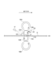
- FIG. 1 is a schematic diagram of a rolling facility to which a liquid adhesion suppressing device according to some embodiments is applied.
- the rolling equipment 100 includes a rolling mill 10 for rolling a metal strip S, and a liquid adhesion suppressor for suppressing liquid adhesion to the surface of the metal strip S rolled by the rolling mill 10.
- a device 20 is provided.
- the rolling mill 10 includes a pair of work rolls 12A, 12B and a pair of support rolls 16A, 16B, which are respectively provided to sandwich a metal strip S, which is a rolled material, from above and below. Further, the rolling mill 10 includes a rolling device (not shown; for example, a hydraulic cylinder) for rolling down the metal strip S by applying a load to the pair of work rolls 12A, 12B.
- a rolling device not shown; for example, a hydraulic cylinder
- the pair of work rolls 12A and 12B include an upper work roll 12A placed above the metal band S and a lower work roll 12B placed below the metal band S.
- the pair of work rolls 12A, 12B are each rotatably supported by bearings (not shown).
- the pair of support rolls 16A and 16B are arranged such that an upper support roll 16A is arranged above the upper work roll 12A so as to be in contact with the upper work roll 12A, and an upper support roll 16A is arranged below the lower work roll 12B so as to be in contact with the lower work roll 12B.
- a lower support roll 16B is disposed.
- the pair of support rolls 16A and 16B are each rotatably supported by bearings (not shown). Support rolls 16A, 16B are configured to support work rolls 12A, 12B.
- the pair of backup rolls correspond to the pair of support rolls 16A and 16B described above.
- the pair of intermediate rolls correspond to the pair of support rolls 16A and 16B described above.
- a motor (not shown) is connected to the work rolls 12A, 12B via a spindle (not shown) or the like, and the work rolls 12A, 12B are rotationally driven by the motor.
- a motor rotates the work rolls 12A, 12B while rolling down the metal strip S with a rolling device, thereby creating a frictional force between the work rolls 12A, 12B and the metal strip S.
- the force causes the metal strip S to be sent to the exit side of the rolling mill 10 (ie, to the downstream side of the rolling mill 10 in the traveling direction of the metal strip S).
- a liquid supply section 17 configured to supply liquid toward the upper work roll 12A is provided on the entry side of the rolling mill 10 (that is, on the upstream side of the rolling mill 10 in the traveling direction of the metal strip S). .
- the liquid supplied from the liquid supply section 17 to the upper work roll 12A may be, for example, a coolant for cooling the upper work roll 12A.
- the coolant may contain water as a main component.
- the liquid adhesion suppressing device 20 suppresses the liquid supplied from the above-mentioned liquid supply section 17 etc. toward the upper work roll 12A from adhering to the surface of the metal strip S on the exit side of the rolling mill 10. configured.
- FIGS. 2 and 3 are schematic views of the rolling equipment according to one embodiment, and are plan views showing the upper work roll 12A and the liquid adhesion suppressing device 20 together with the metal band S.
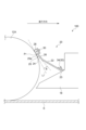
- 4 and 5 are schematic diagrams of a liquid adhesion suppressing device 20 according to an embodiment, respectively.
- the liquid adhesion suppressing device 20 includes a shielding member 22 provided at a position facing the non-contact portion 14 of the upper work roll 12A on the exit side of the rolling mill 10.
- the upper work roll 12A has a contact portion 13 that contacts the metal strip S rolled by the rolling mill 10 and an axial direction of the upper work roll 12A (the upper work roll 12A It includes a non-contact part 14 that is located next to the contact part 13 in the direction of the central axis O (hereinafter also simply referred to as the axial direction) and does not contact the metal band S. That is, the contact portion 13 of the upper work roll 12A is a portion that pinches the metal band S together with the lower work roll 12B, and is a portion that overlaps with the metal band S in a plan view.
- the non-contact portion 14 of the upper work roll 12A is a portion that does not overlap with the metal band S in plan view. Normally, the non-contact portions 14 are present on both sides of the contact portion 13 in the axial direction of the upper work roll 12A.
- the liquid adhesion suppressing device 20 may include a pair of shielding members 22 installed at positions facing the pair of non-contact parts 14 located on both sides of the contact part 13 of the upper work roll 12A. good.
- the liquid adhesion suppressing device 20 may include a shielding member 22 extending in the axial direction from one non-contact portion 14 to the other non-contact portion 14.
- the shielding member 22 is configured to block liquid leaking from the gap between the upper work roll 12A and the lower work roll 12B.
- the gap between the upper work roll 12A and the lower work roll 12B is a gap formed between the non-contact portion 14 of the upper work roll 12A and the lower work roll 12B. Note that since the metal band S exists between the contact portion 13 of the upper work roll 12A and the lower work roll 12B, basically no gap is formed.
- the shielding member 22 is provided near the upper work roll 12A.
- the shielding member 22 may be provided so as to partially overlap the upper work roll 12A in plan view.
- the shielding member 22 may have a facing surface 24 provided to face the surface (roll surface) of the upper work roll 12A.
- the opposing surface 24 can block liquid leaking from the gap between the upper work roll 12A and the lower work roll 12B.
- a part of the liquid (coolant, etc.) supplied toward the upper work roll 12A at the entrance side of the rolling mill 10 is transferred to the gap between the upper work roll 12A and the lower work roll 12B (the non-contact of the upper work roll 12A). 14 and the lower work roll 12B) to the exit side of the rolling mill 10, and a part of the liquid leaked to the exit side of the rolling mill 10 in this way flows into the metal strip S. May adhere to surfaces.
- FIGS. 6A to 7B are diagrams for explaining the operation of the liquid adhesion suppressing device according to some embodiments.
- 6A and 7A are schematic views of the rolling mill including the upper work roll 12A viewed from the exit side.
- 6B and 7B are schematic views of the rolling mill shown in FIGS. 6A and 7B, respectively, viewed from the axial direction of the upper work roll 12A.
- the liquid adhesion suppressing device according to the embodiment of the present invention is not applied.
- FIGS. 7A and 7B a liquid adhesion suppressing device according to an embodiment is applied.
- the reference numeral 101 in these figures indicates the liquid supplied from the liquid supply section 17 toward the upper work roll 12A.
- arrows attached to the upper and lower work rolls 12A, 12B and the upper and lower support rolls 16A, 16B indicate the rotation direction of each roll.
- the reason why some of the leaked liquid adheres to the surface of the metal band S is considered to be due to the following reasons. That is, the liquid leaked to the exit side of the rolling mill 10 is rolled up by the rotating upper work roll 12A due to the Coanda effect (see reference numeral 102 in FIGS. 6A and 6B).
- the liquid rolled up by the upper work roll 12A is dammed up by the upper support roll 16A, which rotates in the opposite direction to the rotation direction of the upper work roll 12A. Therefore, a liquid pool is formed between the upper work roll 12A and the upper support roll 16A (see reference numeral 104 in FIGS. 6A and 6B).
- the liquid is pushed out from the liquid pool in the width direction of the metal strip (that is, in the axial direction of the upper work roll 12A) and falls (see reference numeral 106 in FIGS. 6A and 6B). It adheres to the surface of the metal band S.
- the liquid adhering to the surface of the metal band S in this way becomes a cause of staining, which may lead to a decrease in product quality.
- the shielding member 22 can be installed at a position facing the non-contact portion 14 of the upper work roll 12A on the exit side of the rolling mill 10, the pair of work rolls (upper work roll 12A and The shielding member 22 blocks liquid (coolant, etc.) (see reference numeral 102 in FIGS. 7A and 7B) that leaks from the gap between the lower work rolls 12B to the exit side of the rolling mill 10 and is rolled up by the upper work rolls 12A. (see reference numeral 108 in FIGS. 7A and 7B) and dropped (see reference numeral 110 in FIGS. 7A and 7B). Thereby, formation of a liquid pool (see FIGS.
- the shielding member 22 includes a plate-shaped portion 26 that forms a facing surface 24 that faces the surface of the upper work roll 12A.
- the shielding member 22 including the plate-shaped portion 26 it is possible to suppress the liquid from adhering to the surface of the metal strip S on the exit side of the rolling mill 10 with a simple configuration.
- the shielding member 22 may be supported by the stationary member 18.
- the shielding member 22 is supported by a cobble guard (stationary member) provided near the upper work roll 12A.
- the cobble guard is for preventing the metal band from being wrapped around the rolls of the rolling mill 10 when the metal band is broken during rolling.
- the closest portion 25 of the opposing surface 24 including the closest point 25a closest to the upper work roll 12A is the lowest point 23 of the shielding member 22. located above.
- the closest portion 25 of the opposing surface 24 that is closest to the upper work roll 12A is located above the lowest point 23 of the shielding member 22, so that the closest portion 25 of the opposing surface 24 and , and the tangent line LT of the upper work roll 12A tends to be an acute angle. Therefore, even if the shielding member 22 including the opposing surface 24 and the upper work roll 12A come into contact, the surfaces slide against each other, so that the shielding member 22 or the upper work roll 12A is unlikely to be damaged.
- the tangent line LT of the upper work roll 12A at the position PT closest to the shielding member 22, and the closest point 25a of the opposing surface 24 closest to the upper work roll 12A is an acute angle.
- the angle ⁇ formed between the above-mentioned closest portion 25 of the opposing surface 24 and the above-mentioned tangent line LT may be 60 degrees or less.
- the angle ⁇ formed between the closest portion 25 of the opposing surface 24 and the tangent line LT to the upper work roll 12A is an acute angle. Therefore, even if the shielding member 22 including the opposing surface 24 and the upper work roll 12A come into contact, the surfaces slide against each other, so that the shielding member 22 or the upper work roll 12A is unlikely to be damaged.
- the liquid adhesion suppressing device 20 includes a biasing member 32 for biasing the shielding member 22 toward the upper work roll 12A.
- the shielding member 22 is supported by the stationary member 18 via a biasing member 32.
- the shielding member 22 is supported by the stationary member 18 via the biasing member 32, and the biasing member 32 biases the shielding member 22 toward the upper work roll 12A.
- 22 can be easily positioned at the appropriate position. For example, when the position of the upper work roll 12A is changed due to a change in the target plate thickness, the position of the shielding member 22 with respect to the upper work roll 12A becomes appropriate without making detailed positional adjustments of the shielding member 22.
- the shielding member 22 can be positioned as shown in FIG.
- biasing member 32 described above may include an elastic member such as a spring.
- biasing member 32 includes a leaf spring 34 attached to stationary member 18 and configured to bias shielding member 22 toward upper work roll 12A. including.
- the shielding member 22 since the shielding member 22 is biased toward the upper work roll 12A using the elastic member, the shielding member 22 can be easily positioned at an appropriate position. For example, when the position of the upper work roll is changed due to a change in target plate thickness, the shielding member 22 can be appropriately positioned without making detailed positional adjustments of the shielding member.
- the liquid adhesion suppressing device 20 is attached to the shielding member 22 and provided in contact with the surface of the upper work roll 12A.
- the contact member 28 has a friction coefficient smaller than that between the upper work roll 12A and the shielding member 22.
- contact member 28 is attached to shielding member 22 by bolts 30.
- FIGS. 4 and 5 In the exemplary embodiment shown in FIGS.
- the contact member 28 having a relatively small coefficient of friction with the upper work roll 12A is attached to the shielding member 22, and the contact member 28 is provided so as to contact the upper work roll 12A. Therefore, the shielding member 22 can be maintained at a position where it does not contact the upper work roll 12A via the contact member 28, and even if the contact member 28 and the upper work roll 12A slide, the contact member 28 and Since the upper work roll 12A is less prone to wear and the like, the frequency of replacement of the contact member 28 or the upper work roll 12A can be reduced.
- the contact member 28 may be provided only in a part of the area in which the shielding member 22 extends in the axial direction. Further, a plurality of contact members 28 may be arranged along the axial direction.
- one or more contact members 28 may be provided for each of the plurality of shielding members 22.
- one or more contact members 28 may be provided with respect to the shielding member 22.
- the contact member 28 may be provided so as to be in contact with the surface of the non-contact portion 14 of the upper work roll 12A, or may be provided so as to be in contact with the surface of the contact portion 13 of the upper work roll 12A.
- the above-mentioned contact member 28 may be formed from a graphite fiber reinforced resin composite material.
- the contact member 28 is formed from a graphite fiber reinforced resin composite material that has self-lubricating properties and has a small coefficient of friction with metal materials, wear that may occur on the contact member 28 and the upper work roll 12A is effectively reduced. can be suppressed.
- the above graphite fiber reinforced resin composite material may include a graphite fiber reinforced polyimide resin composite material.
- the liquid adhesion suppressing device (20) includes: A liquid adhesion suppressing device for suppressing liquid adhesion to the surface of a metal strip (S) rolled by a rolling mill (10) including an upper work roll (12A) and a lower work roll (12B),
- the upper work roll has a contact portion (13) that contacts the metal strip rolled by the rolling mill, and a non-contact portion that is located next to the contact portion in the axial direction of the upper work roll and does not contact the metal strip.
- Part (14) configured to be installed at a position facing the non-contact portion of the upper work roll on the exit side of the rolling mill, and for blocking liquid leaking from a gap between the upper work roll and the lower work roll.
- a shielding member (22) is provided.
- the shielding member can be installed at a position facing the non-contact part of the upper work roll on the exit side of the rolling mill, it is possible to install the shielding member between the pair of work rolls (the upper work roll and the lower work roll).
- the liquid (coolant, etc.) that leaks from the gap to the exit side of the rolling mill and is rolled up by the upper work roll can be blocked by the shielding member and allowed to fall.
- formation of a liquid pool between the upper work roll and the upper support roll (backup roll or intermediate roll) can be suppressed. Therefore, according to the configuration (1) above, with a simple configuration using a shielding member, it is possible to suppress the liquid from adhering to the surface of the metal strip on the exit side of the rolling mill.
- the shielding member has a facing surface (24) provided to face the surface of the upper work roll.
- the shielding member since the shielding member has a facing surface provided to face the surface of the upper work roll, leakage from the gap between the pair of work rolls to the exit side of the rolling mill causes the upper work roll to leak to the exit side of the rolling mill.
- the liquid rolled up by the work roll can be blocked by the opposing surface of the shielding member and allowed to fall. Thereby, formation of a liquid pool between the upper work roll and the upper support roll can be suppressed. Therefore, it is possible to suppress the liquid from adhering to the surface of the metal strip on the exit side of the rolling mill.
- the closest portion (25) including the closest point (25a) closest to the upper work roll is located above the lowest point (23) of the shielding member.
- the closest portion of the opposing surface including the closest point closest to the upper work roll is located above the lowest point of the shielding member, so the closest portion of the opposing surface includes the closest point closest to the upper work roll.
- the angle formed between this and the tangent to the upper work roll tends to be acute. Therefore, even if the shielding member including the opposing surface comes into contact with the upper work roll, the shielding member or the upper work roll is unlikely to be damaged.
- the tangent line (L T ) of the upper work roll at the position closest to the shielding member, and the tangent line (L The angle ( ⁇ ) formed with the shielding member is an acute angle.
- the angle formed between the closest portion of the facing surface that includes the closest point closest to the upper work roll and the tangent to the upper work roll is an acute angle. Therefore, even if the shielding member including the opposing surface comes into contact with the upper work roll, the shielding member or the upper work roll is unlikely to be damaged.
- the shielding member includes a plate-shaped portion (26) forming the opposing surface.
- the shielding member since the shielding member includes the plate-shaped portion forming the above-mentioned opposing surface, the shielding member has a simple configuration using the plate-shaped portion, and can be rolled as described in (1) above. It is possible to prevent liquid from adhering to the surface of the metal strip on the exit side.
- any of the configurations (1) to (5) above It is attached to the shielding member and is provided so as to be in contact with the surface of the upper work roll, and has a coefficient of friction with the upper work roll that is smaller than a coefficient of friction between the upper work roll and the shielding member.
- a contact member (28) is provided.
- a contact member having a relatively small coefficient of friction with the upper work roll is attached to the shielding member, and the contact member is provided so as to contact the upper work roll. Therefore, the shielding member can be maintained at a position where it does not come into contact with the upper work roll via the contact member, and even if the contact member and the upper work roll slide, the contact member and the upper work roll will not be subject to wear or the like. Since this is less likely to occur, the frequency of replacement of the contact member or the upper work roll can be reduced.
- the contact member is formed from a graphite fiber reinforced resin composite material.
- the contact member is formed from a graphite fiber reinforced resin composite material that has self-lubricating properties and has a small coefficient of friction with metal materials, The resulting wear can be effectively suppressed.
- the graphite fiber reinforced resin composite material includes a graphite fiber reinforced polyimide resin composite material.
- any of the configurations (1) to (8) above comprising a biasing member (32) for biasing the shielding member toward the upper work roll;
- the shielding member is configured to be supported by the stationary member via the biasing member.
- the shielding member is supported by the stationary member via the biasing member, and the biasing member biases the shielding member toward the upper work roll.
- the shielding member can be easily positioned in the appropriate position. For example, when the position of the upper work roll is changed due to a change in the target plate thickness, the shielding member can be appropriately positioned without making detailed positional adjustments to the shielding member.
- the biasing member includes an elastic member.
- the shielding member since the shielding member is biased toward the upper work roll using the elastic member, the shielding member can be easily positioned at an appropriate position. For example, when the position of the upper work roll is changed due to a change in the target plate thickness, the shielding member can be appropriately positioned without making detailed positional adjustments to the shielding member.
- the rolling equipment (100) includes: a rolling mill (10) including an upper work roll (12A) and a lower work roll (12B);
- the liquid adhesion suppressing device (20) according to any one of (1) to (10) above, configured to suppress adhesion of liquid to the surface of a metal strip rolled by the rolling mill; Equipped with.
- the shielding member can be installed at a position facing the non-contact portion of the upper work roll on the exit side of the rolling mill, so that the shielding member can be installed between the pair of work rolls (the upper work roll and the lower work roll).
- the liquid (coolant, etc.) that leaks from the gap to the exit side of the rolling mill and is rolled up by the upper work roll can be blocked by the shielding member and allowed to fall.
- formation of a liquid pool between the upper work roll and the upper support roll (backup roll or intermediate roll) can be suppressed. Therefore, according to the configuration (11) above, with a simple configuration using a shielding member, it is possible to suppress the liquid from adhering to the surface of the metal strip on the exit side of the rolling mill.
- a liquid supply section (17) is provided on the inlet side of the rolling mill and configured to supply liquid toward the upper work roll.
- the supply is supplied toward the upper work roll at the entrance side of the rolling mill, leaks from the gap between the pair of work rolls to the exit side of the rolling mill, and is rolled up by the upper work roll.
- the liquid can be blocked and allowed to fall by the shielding member. Thereby, formation of a liquid pool between the upper work roll and the upper support roll (backup roll or intermediate roll) can be suppressed. Therefore, according to the configuration (12) above, with a simple configuration using a shielding member, it is possible to suppress the liquid from adhering to the surface of the metal strip on the exit side of the rolling mill.
- expressions expressing shapes such as a square shape or a cylindrical shape do not only mean shapes such as a square shape or a cylindrical shape in a strict geometric sense, but also within the range where the same effect can be obtained. , shall also represent shapes including uneven parts, chamfered parts, etc.
- the expressions "comprising,””including,” or “having" one component are not exclusive expressions that exclude the presence of other components.
Landscapes
- Engineering & Computer Science (AREA)
- Mechanical Engineering (AREA)
- Metal Rolling (AREA)
Priority Applications (3)
| Application Number | Priority Date | Filing Date | Title |
|---|---|---|---|
| CN202280096934.2A CN119278104A (zh) | 2022-09-06 | 2022-09-06 | 液体附着抑制装置以及轧制设备 |
| PCT/JP2022/033393 WO2024052983A1 (ja) | 2022-09-06 | 2022-09-06 | 液体付着抑制装置及び圧延設備 |
| JP2024545307A JPWO2024052983A1 (https=) | 2022-09-06 | 2022-09-06 |
Applications Claiming Priority (1)
| Application Number | Priority Date | Filing Date | Title |
|---|---|---|---|
| PCT/JP2022/033393 WO2024052983A1 (ja) | 2022-09-06 | 2022-09-06 | 液体付着抑制装置及び圧延設備 |
Publications (1)
| Publication Number | Publication Date |
|---|---|
| WO2024052983A1 true WO2024052983A1 (ja) | 2024-03-14 |
Family
ID=90192319
Family Applications (1)
| Application Number | Title | Priority Date | Filing Date |
|---|---|---|---|
| PCT/JP2022/033393 Ceased WO2024052983A1 (ja) | 2022-09-06 | 2022-09-06 | 液体付着抑制装置及び圧延設備 |
Country Status (3)
| Country | Link |
|---|---|
| JP (1) | JPWO2024052983A1 (https=) |
| CN (1) | CN119278104A (https=) |
| WO (1) | WO2024052983A1 (https=) |
Citations (3)
| Publication number | Priority date | Publication date | Assignee | Title |
|---|---|---|---|---|
| JPH07290123A (ja) * | 1994-04-21 | 1995-11-07 | Nisshin Steel Co Ltd | 金属帯の調質圧延機および方法 |
| JP2005088767A (ja) * | 2003-09-18 | 2005-04-07 | Fuiisa Kk | ワイパーブレード及びその製造方法並びにワイパー |
| JP2017100146A (ja) * | 2015-11-30 | 2017-06-08 | Jfeスチール株式会社 | 冷間圧延機の冷却液落下防止装置 |
Family Cites Families (2)
| Publication number | Priority date | Publication date | Assignee | Title |
|---|---|---|---|---|
| JPS5610403Y2 (https=) * | 1976-07-13 | 1981-03-09 | ||
| JPS60160903U (ja) * | 1984-03-30 | 1985-10-25 | 日新製鋼株式会社 | 圧延ロ−ルの付着異物除去装置 |
-
2022
- 2022-09-06 WO PCT/JP2022/033393 patent/WO2024052983A1/ja not_active Ceased
- 2022-09-06 CN CN202280096934.2A patent/CN119278104A/zh active Pending
- 2022-09-06 JP JP2024545307A patent/JPWO2024052983A1/ja active Pending
Patent Citations (3)
| Publication number | Priority date | Publication date | Assignee | Title |
|---|---|---|---|---|
| JPH07290123A (ja) * | 1994-04-21 | 1995-11-07 | Nisshin Steel Co Ltd | 金属帯の調質圧延機および方法 |
| JP2005088767A (ja) * | 2003-09-18 | 2005-04-07 | Fuiisa Kk | ワイパーブレード及びその製造方法並びにワイパー |
| JP2017100146A (ja) * | 2015-11-30 | 2017-06-08 | Jfeスチール株式会社 | 冷間圧延機の冷却液落下防止装置 |
Also Published As
| Publication number | Publication date |
|---|---|
| CN119278104A (zh) | 2025-01-07 |
| JPWO2024052983A1 (https=) | 2024-03-14 |
Similar Documents
| Publication | Publication Date | Title |
|---|---|---|
| KR101152855B1 (ko) | 내연기관의 슬라이딩베어링 및 슬라이딩베어링장치 | |
| CN101793490A (zh) | 纸片状介质的厚度检测装置 | |
| WO2024052983A1 (ja) | 液体付着抑制装置及び圧延設備 | |
| CN108700116A (zh) | 径向轴承及旋转机械 | |
| EP2620232B1 (en) | Rolling facility with linear bearing plate for rolling mill | |
| CN216175334U (zh) | 板带冷轧机支撑辊装置 | |
| US8584500B2 (en) | Lubrication delivery system for linear bearings | |
| CN104583488A (zh) | 密封装置和带有密封装置的辊子 | |
| EP1670599A1 (en) | Neck seal for rolling mill oil film bearing | |
| KR100632768B1 (ko) | 크로스롤 압연기 및 그것을 사용한 압연 방법 | |
| JP7832966B2 (ja) | ワイピング装置及び圧延設備 | |
| JP4820062B2 (ja) | クロスロール圧延機及びそれを用いた圧延方法 | |
| WO2025234058A1 (ja) | 液体付着抑制装置及び圧延設備 | |
| KR20090055010A (ko) | 스트립 실링 게이트 | |
| Kato et al. | The standardization for the edge quality of the precise machining products | |
| KR20020076505A (ko) | 하이브리드형 공기 베어링을 사용한 로울러 | |
| CN114278743A (zh) | 一种阀板磨损自补偿的无泄漏旋转供料器 | |
| JP3514019B2 (ja) | 圧延機の水切り装置 | |
| JP7673201B2 (ja) | ワイピング装置及び圧延設備 | |
| JP3560861B2 (ja) | 板材圧延設備 | |
| JP7673200B2 (ja) | ワイピング装置及び圧延設備 | |
| KR20200127149A (ko) | 이물질 제거형 강판 이송롤 | |
| Brewe et al. | Geometry and starvation effects in hydrodynamic lubrication | |
| CN105603822A (zh) | 密封刮刀 | |
| JPH06320206A (ja) | フランジを有する形鋼の圧延法およびその装置 |
Legal Events
| Date | Code | Title | Description |
|---|---|---|---|
| 121 | Ep: the epo has been informed by wipo that ep was designated in this application |
Ref document number: 22958062 Country of ref document: EP Kind code of ref document: A1 |
|
| WWE | Wipo information: entry into national phase |
Ref document number: 2024545307 Country of ref document: JP |
|
| WWE | Wipo information: entry into national phase |
Ref document number: 202280096934.2 Country of ref document: CN |
|
| WWP | Wipo information: published in national office |
Ref document number: 202280096934.2 Country of ref document: CN |
|
| NENP | Non-entry into the national phase |
Ref country code: DE |
|
| 122 | Ep: pct application non-entry in european phase |
Ref document number: 22958062 Country of ref document: EP Kind code of ref document: A1 |