WO2024048668A1 - 情報処理装置、情報処理方法および情報処理プログラム - Google Patents
情報処理装置、情報処理方法および情報処理プログラム Download PDFInfo
- Publication number
- WO2024048668A1 WO2024048668A1 PCT/JP2023/031590 JP2023031590W WO2024048668A1 WO 2024048668 A1 WO2024048668 A1 WO 2024048668A1 JP 2023031590 W JP2023031590 W JP 2023031590W WO 2024048668 A1 WO2024048668 A1 WO 2024048668A1
- Authority
- WO
- WIPO (PCT)
- Prior art keywords
- link
- structure diagram
- peripheral
- user terminal
- display
- Prior art date
- Legal status (The legal status is an assumption and is not a legal conclusion. Google has not performed a legal analysis and makes no representation as to the accuracy of the status listed.)
- Ceased
Links
Images

































Classifications
-
- G—PHYSICS
- G06—COMPUTING OR CALCULATING; COUNTING
- G06F—ELECTRIC DIGITAL DATA PROCESSING
- G06F3/00—Input arrangements for transferring data to be processed into a form capable of being handled by the computer; Output arrangements for transferring data from processing unit to output unit, e.g. interface arrangements
- G06F3/01—Input arrangements or combined input and output arrangements for interaction between user and computer
- G06F3/048—Interaction techniques based on graphical user interfaces [GUI]
- G06F3/0481—Interaction techniques based on graphical user interfaces [GUI] based on specific properties of the displayed interaction object or a metaphor-based environment, e.g. interaction with desktop elements like windows or icons, or assisted by a cursor's changing behaviour or appearance
-
- G—PHYSICS
- G06—COMPUTING OR CALCULATING; COUNTING
- G06F—ELECTRIC DIGITAL DATA PROCESSING
- G06F3/00—Input arrangements for transferring data to be processed into a form capable of being handled by the computer; Output arrangements for transferring data from processing unit to output unit, e.g. interface arrangements
- G06F3/01—Input arrangements or combined input and output arrangements for interaction between user and computer
- G06F3/048—Interaction techniques based on graphical user interfaces [GUI]
- G06F3/0484—Interaction techniques based on graphical user interfaces [GUI] for the control of specific functions or operations, e.g. selecting or manipulating an object, an image or a displayed text element, setting a parameter value or selecting a range
- G06F3/04842—Selection of displayed objects or displayed text elements
-
- G—PHYSICS
- G06—COMPUTING OR CALCULATING; COUNTING
- G06F—ELECTRIC DIGITAL DATA PROCESSING
- G06F3/00—Input arrangements for transferring data to be processed into a form capable of being handled by the computer; Output arrangements for transferring data from processing unit to output unit, e.g. interface arrangements
- G06F3/01—Input arrangements or combined input and output arrangements for interaction between user and computer
- G06F3/048—Interaction techniques based on graphical user interfaces [GUI]
- G06F3/0481—Interaction techniques based on graphical user interfaces [GUI] based on specific properties of the displayed interaction object or a metaphor-based environment, e.g. interaction with desktop elements like windows or icons, or assisted by a cursor's changing behaviour or appearance
- G06F3/0482—Interaction with lists of selectable items, e.g. menus
-
- G—PHYSICS
- G06—COMPUTING OR CALCULATING; COUNTING
- G06F—ELECTRIC DIGITAL DATA PROCESSING
- G06F3/00—Input arrangements for transferring data to be processed into a form capable of being handled by the computer; Output arrangements for transferring data from processing unit to output unit, e.g. interface arrangements
- G06F3/01—Input arrangements or combined input and output arrangements for interaction between user and computer
- G06F3/048—Interaction techniques based on graphical user interfaces [GUI]
- G06F3/0484—Interaction techniques based on graphical user interfaces [GUI] for the control of specific functions or operations, e.g. selecting or manipulating an object, an image or a displayed text element, setting a parameter value or selecting a range
- G06F3/0486—Drag-and-drop
-
- G—PHYSICS
- G06—COMPUTING OR CALCULATING; COUNTING
- G06F—ELECTRIC DIGITAL DATA PROCESSING
- G06F40/00—Handling natural language data
-
- G—PHYSICS
- G06—COMPUTING OR CALCULATING; COUNTING
- G06Q—INFORMATION AND COMMUNICATION TECHNOLOGY [ICT] SPECIALLY ADAPTED FOR ADMINISTRATIVE, COMMERCIAL, FINANCIAL, MANAGERIAL OR SUPERVISORY PURPOSES; SYSTEMS OR METHODS SPECIALLY ADAPTED FOR ADMINISTRATIVE, COMMERCIAL, FINANCIAL, MANAGERIAL OR SUPERVISORY PURPOSES, NOT OTHERWISE PROVIDED FOR
- G06Q10/00—Administration; Management
- G06Q10/10—Office automation; Time management
-
- G—PHYSICS
- G06—COMPUTING OR CALCULATING; COUNTING
- G06Q—INFORMATION AND COMMUNICATION TECHNOLOGY [ICT] SPECIALLY ADAPTED FOR ADMINISTRATIVE, COMMERCIAL, FINANCIAL, MANAGERIAL OR SUPERVISORY PURPOSES; SYSTEMS OR METHODS SPECIALLY ADAPTED FOR ADMINISTRATIVE, COMMERCIAL, FINANCIAL, MANAGERIAL OR SUPERVISORY PURPOSES, NOT OTHERWISE PROVIDED FOR
- G06Q10/00—Administration; Management
- G06Q10/40—Business processes related to social networking or social networking services
Definitions
- the present invention relates to an information processing device, an information processing method, and an information processing program.
- Patent Document 1 discloses a technology in which an individual's thought pattern is represented as a topology graph, conceptual correspondence data as constituent elements are arranged as connection nodes, and the connection nodes are connected by connection links.
- Cited Document 2 discloses a technique for extracting and aggregating analyzes, opinions, and criticisms from multiple users for a structured thinking/argument process, and confirming relationships between elements.
- An object of the present invention is to provide a technology that solves the above problems.
- an information processing device includes: a central element acquisition unit that acquires a central element that is the center of thinking; a central element display instruction unit that instructs a user terminal to display the central element; a peripheral element acquisition unit that acquires a first peripheral element associated with the central element; a peripheral element display instruction unit that instructs the user terminal to display the first peripheral element around the central element; a link acquisition unit that acquires a first link between the central element and the first peripheral element; a link display instruction unit that instructs the user terminal to display the first link between the central element and the first peripheral element; Equipped with
- the information processing method includes: a central element acquisition step of acquiring a central element that is the center of thinking; a central element display instruction step of instructing the user terminal to display the central element; a peripheral element acquisition step of acquiring a first peripheral element associated with the central element; a peripheral element display instruction step of instructing the user terminal to display the first peripheral element around the central element; a link obtaining step of obtaining a first link between the central element and the first peripheral element; a link display instruction step of instructing the user terminal to display the first link between the central element and the first peripheral element; including.
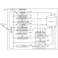
- FIG. 1 is a block diagram showing the configuration of an information processing system according to a first embodiment.
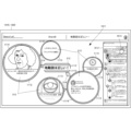
- FIG. 7 is a diagram showing a display screen of a user terminal in an information processing system according to a second embodiment.
- FIG. 7 is a diagram showing a display screen of a user terminal in an information processing system according to a second embodiment.
- FIG. 7 is a diagram illustrating an overview of operations of a user terminal in an information processing system according to a second embodiment.
- FIG. 7 is a diagram illustrating an overview of subject input at a user terminal of an information processing system according to a second embodiment.
- FIG. 7 is a diagram illustrating an overview of element input on a user terminal of an information processing system according to a second embodiment.
- FIG. 7 is a diagram illustrating an overview of link input at a user terminal of an information processing system according to a second embodiment.
- FIG. 7 is a diagram illustrating an overview of a thought structure diagram registration request in a user terminal of an information processing system according to a second embodiment.
- FIG. 7 is a diagram illustrating an overview of editing instructions from a user terminal of an information processing system according to a second embodiment.
- FIG. 2 is a block diagram showing the configuration of an information processing system according to a second embodiment.
- FIG. 7 is a sequence diagram showing the operation procedure of the information processing system according to the second embodiment.
- FIG. 2 is a block diagram showing the functional configuration of a ShareB server as an information processing device according to a second embodiment.
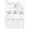
- FIG. 7 is a diagram showing the configuration of a database according to a second embodiment.
- FIG. 7 is a diagram showing the configuration of a database according to a second embodiment. It is a figure which shows the structure of the thought structure diagram generation table based on 2nd Embodiment.
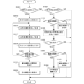
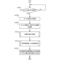
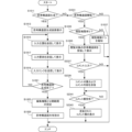
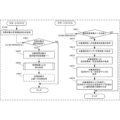
- FIG. 2 is a block diagram showing the hardware configuration of a ShareB server according to a second embodiment. It is a flowchart which shows the processing procedure of the ShareB server based on 2nd Embodiment. It is a flowchart which shows the procedure of thought structure diagram generation processing concerning a 2nd embodiment.
- FIG. 2 is a block diagram showing the functional configuration of a user terminal according to a second embodiment. It is a flowchart which shows the processing procedure of the user terminal based on 2nd Embodiment.
- FIG. 7 is a diagram showing a voting operation of a user terminal in an information processing system according to a third embodiment.
- FIG. 7 is a diagram showing a display screen of a user terminal based on voting in an information processing system according to a third embodiment.
- FIG. 7 is a diagram showing a display screen of a user terminal based on voting in an information processing system according to a third embodiment.
- FIG. 2 is a block diagram showing the configuration of an information processing system according to a third embodiment.
- FIG. 7 is a sequence diagram showing an operation procedure of an information processing system according to a third embodiment.
- FIG. 7 is a sequence diagram showing an operation procedure of an information processing system according to a third embodiment.
- FIG. 7 is a sequence diagram showing an operation procedure of an information processing system according to a third embodiment.
- FIG. 7 is a block diagram showing the functional configuration of a ShareB server as an information processing device according to a third embodiment.
- FIG. 7 is a diagram showing the configuration of a database according to a third embodiment.
- FIG. 7 is a diagram showing the configuration of a database according to a third embodiment. It is a figure which shows the structure of the voting result aggregation table based on 3rd Embodiment. It is a figure which shows the structure of the thinking structure diagram correction table based on 3rd Embodiment.
- FIG. 7 is a diagram showing the configuration of a database according to a third embodiment. It is a figure which shows the structure of the voting result aggregation table based on 3rd Embodiment.
- FIG. 3 is a block diagram showing the functional configuration of a user terminal according to a third embodiment. It is a flowchart which shows the processing procedure of the user terminal based on 3rd Embodiment.
- FIG. 7 is a diagram showing a display screen of a user terminal in an information processing system according to a fourth embodiment.
- FIG. 12 is a block diagram showing the functional configuration of a ShareB server as an information processing device according to a fourth embodiment. It is a figure showing the composition of the database concerning a 4th embodiment. It is a figure showing the composition of the database concerning a 4th embodiment. It is a figure showing the composition of the comment display table concerning a 4th embodiment. It is a flowchart which shows the processing procedure of the ShareB server based on 4th Embodiment. It is a flowchart which shows the processing procedure of the ShareB server based on 4th Embodiment.
- FIG. 3 is a block diagram showing the functional configuration of a user terminal according to a fourth embodiment.
- FIG. 7 is a diagram showing a display screen of a user terminal in an information processing system according to a fifth embodiment. It is a figure showing other display screens of a user terminal in an information processing system concerning a 5th embodiment. It is a figure showing other display screens of a user terminal in an information processing system concerning a 5th embodiment. It is a figure showing other display screens of a user terminal in an information processing system concerning a 5th embodiment. It is a figure showing voting operation of a user terminal in an information processing system concerning a 6th embodiment.
- FIG. 12 is a sequence diagram illustrating a voting operation procedure in an information processing system according to a sixth embodiment.
- FIG. 7 is a diagram showing a display screen of a user terminal in an information processing system according to an eighth embodiment. It is a figure which shows the link generation table based on 8th Embodiment. It is a flowchart which shows the processing procedure of the information processing device concerning an 8th embodiment. It is a figure showing the display screen of the user terminal in the information processing system concerning a 9th embodiment.
- FIG. 7 is a diagram showing a display screen of a user terminal in an information processing system according to a tenth embodiment.
- FIG. 7 is a diagram showing a display screen of a user terminal in an information processing system according to an eleventh embodiment.
- FIG. 7 is a diagram showing a display screen of a user terminal in an information processing system according to an eleventh embodiment.
- FIG. 7 is a diagram showing a display screen of a user terminal in an information processing system according to a twelfth embodiment.
- FIG. 7 is a diagram showing a display screen of a user terminal in an information processing system according to a thirteenth embodiment.
- FIG. 7 is a diagram showing a display screen of a user terminal in an information processing system according to a fourteenth embodiment.
- FIG. 7 is a diagram showing a display screen of a user terminal in an information processing system according to a fourteenth embodiment.
- FIG. 7 is a diagram showing a display screen of a user terminal in an information processing system according to a fourteenth embodiment.
- FIG. 7 is a diagram showing a display screen of a user terminal in an information processing system according to a fifteenth embodiment.
- FIG. 7 is a diagram showing a display screen of a user terminal in an information processing system according to a fifteenth embodiment.
- FIG. 7 is a diagram showing a display screen of a user terminal in an information processing system according to a fifteenth embodiment.
- FIG. 7 is a diagram showing a display screen of a user terminal in an information processing system according to a fifteenth embodiment.
- FIG. 7 is a diagram showing a display screen of a user terminal in an information processing system according to a sixteenth embodiment.
- FIG. 7 is a diagram showing a display screen of a user terminal in an information processing system according to a sixteenth embodiment.
- FIG. 7 is a diagram showing a display screen of a user terminal in an information processing system according to a sixteenth embodiment.
- FIG. 7 is a diagram showing a display screen of a user terminal in an information processing system according to a seventeenth embodiment.
- FIG. 7 is a diagram showing a display screen of a user terminal in an information processing system according to a seventeenth embodiment.
- FIG. 7 is a diagram showing a display screen of a user terminal in an information processing system according to a seventeenth embodiment.
- FIG. 7 is a block diagram showing the functional configuration of an information processing device according to an eighteenth embodiment.
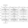
- FIG. 12 is a diagram showing the configuration of a thought structure diagram generation table according to the eighteenth embodiment. 12 is a flowchart showing a processing procedure of an information processing apparatus according to an eighteenth embodiment. 12 is a flowchart showing a processing procedure of an information processing apparatus according to an eighteenth embodiment.
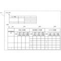
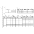
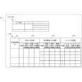
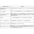
- the functions and specific contents related to the thought structure diagram according to the embodiment of the present invention are summarized in a table.
- the functions and specific contents related to the thought structure diagram according to the embodiment of the present invention are summarized in a table.
- “elements” are not limited to news, statistics, dictionaries, wiki contents, videos, audio data, SNS posts, people, living things, events, all kinds of substances, concepts, ideas, words, real and fictional entities, It is used as a concept that includes everything that humans can recognize, whether tangible or intangible.
- the thought structure diagram itself becomes an “element”, and it is also possible to create a larger hierarchical thought structure diagram.
- the central elements such as ⁇ theme'' and ⁇ proposition'' express the topic or problem that is central to thinking.
- “peripheral elements” represent materials and information that serve as thinking materials for guiding the "central element.” For example, peripheral elements such as news, wiki, and images from external sites can be imported by inputting a URL.
- a “link” represents a connection indicating a relationship between a central element and peripheral elements or a relationship between peripheral elements and peripheral elements. Note that when a certain "peripheral element” is taken up as a topic or problem that becomes the center of thinking, that "peripheral element” can change into a “central element.” Also, a proposition is the content expressed by a declarative sentence that is true or false, and a subject is the object that the sentence is talking about.
- the information processing apparatus 100 is a device for expressing thought structures.
- the information processing device 100 includes a central element acquisition section 101, a central element display instruction section 102, a peripheral element acquisition section 103, a peripheral element display instruction section 104, a link acquisition section 105, and a link acquisition section 105.
- a display instruction section 106 is included.
- the central element acquisition unit 101 acquires a central element as a graphical element that is the center of thought.
- the central element display instruction unit 102 instructs the user terminal 110 to display the central element.
- the peripheral element acquisition unit 103 acquires peripheral elements as graphic elements related to the central element.
- the peripheral element display instruction unit 104 instructs the user terminal 110 to display peripheral elements around the central element.
- the link acquisition unit 105 acquires links between the central element and peripheral elements.
- the link display instruction unit 106 instructs the user terminal 110 to display a link between the central element and the peripheral elements.
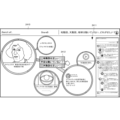
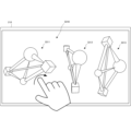
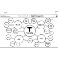
- FIG. 2A is a diagram showing a display screen 201 of the user terminal 210 according to the present embodiment.
- the display screen 201 is also called a canvas, and is a representation of a thinking structure that can be understood at a glance by arranging various elements via links.
- the themes 203 which are the three peripheral elements, include “heliocentrism,” “Renaissance,” and “religious reform.” These subjects 203 are also linked to each other or via peripheral elements 204 (eg, element "typography”).
- One of the themes 203, “Heliocentrism,” is linked to Proposition 212, "Heliocentrism is correct! as a peripheral element.
- Proposition 212 By zooming in on Proposition 212, "The heliocentric theory is correct!, a thought structure diagram with the proposition "The heliocentric theory is correct! as a central element appears.
- one thought structure diagram itself becomes an "element” in this way, and it is possible to create a larger hierarchical thought structure diagram.
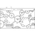
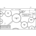
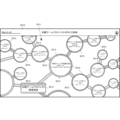
- FIG. 2B is a diagram showing the display screen 211 of the user terminal 210 in the information processing system according to this embodiment.
- the display screen 211 is a thought structure centered on the proposition 212, "Heliocentrism is correct," which is one peripheral element of the display screen 201.
- the display screen 211 of the user terminal 210 of the user who generates the thought structure diagram shows a proposition 212 as a central element that is the center of thought, a plurality of peripheral elements 213 related to the proposition 212, and a combination of the proposition 212 and peripheral elements 213.
- a thought structure diagram is displayed, which is made up of links 214 that connect the elements 214 and links 215 that connect the plurality of peripheral elements 213.
- the links 214 and 215 include links indicated by arrows (triangles ⁇ ), links indicated by rectangles ( ⁇ ), and links indicated by diamonds ( ⁇ ).
- a link indicated by an arrow (triangle ⁇ ) indicates the direction of a causal relationship (parent-child relationship), that is, a relationship that acts from one side but cannot be the other way around.
- a link indicated by a rectangle ( ⁇ ) indicates a relationship in which there is no causal relationship or superiority of information exists, but there is a possibility of mutual interaction.
- Links indicated by diamonds ( ⁇ ) indicate conflicting relationships or contradictory information. Note that the shape of the link on the display screen 211 is just an example, and may be changed depending on differences in expression standards in the thought structure diagram, voting results, etc. described later.
- the proposition 212 as a central element is "Heliocentrism is correct!, and as a peripheral element 213 linked to the proposition 212, for example, "Copernicus” as a peripheral element that supports proposition 212 is causal. It is linked to Proposition 212 by an unrelated rectangle.
- "Eudoxos" a peripheral element that does not support Proposition 212, is linked with a diamond ( ⁇ ) opposing link.
- "Eudoxus” may be linked to proposition 212 by a rectangle with no causal relationship.
- peripheral element 213 that is linked to the peripheral element 213, for example, "Ptolemy's geocentric theory” as a peripheral element that supports the peripheral element "Eudoxus” is linked by a triangle having a causal relationship.
- Proposition 212, "Heliocentric theory is correct!” is a proposition that asks “Yes” or "No,” but for example, "What is the true shape of this universe?" asks "Heliocentric theory” or "Heliocentric theory”. It may be a proposition to ask.
- the size of the figure representing the peripheral element 213 indicates the degree of influence of the central element of the peripheral element 213 on the proposition 212 as considered by the user who generates the thought structure diagram, and the larger the size, the greater the influence. (In the third embodiment described later, the number of votes also influences).
- the influence on the central element can be indicated by the opacity of the peripheral elements rather than the size. Note that, without being limited to size or opacity, a display method is used that allows the user to easily grasp the structure of the thought structure diagram and the influence of peripheral elements on the central element through visual confirmation. For example, elements may be displayed with broken lines, or their colors may be changed.
- the display screen 205 on the user terminals 210 and 220 is a menu that is displayed when the application of this embodiment is started.
- the menu includes structure diagram creation and structure diagram viewing.
- the screen transitions to a structural diagram creation screen 206.
- structural diagram viewing if the user has viewing authority, the screen transitions to a structural diagram viewing screen 216.
- menus for structural diagram registration and structural diagram correction are displayed on the creation screen 206.
- the screen transitions to a structural diagram registration screen 207, and menus for viewing authority settings, editing authority settings, and voting authority settings are displayed. If authority setting is required, at least one of the viewing authority setting, editing authority setting, and voting authority setting is selected and the authority setting is accepted. Note that the voting authority settings are authority settings related to the third embodiment.
- the structural diagram to be viewed is displayed, and a menu for editing the structural diagram is displayed.
- the screen transitions to an editing screen 217 if the user has editing authority. Editing by the user is accepted on the editing screen 217.
- voting screen 218 that accepts votes for each element (theme/proposition, peripheral elements, links).
- votes for peripheral elements can be expressed by users who "support the theme” (theme support), “deny the theme” (theme negation), and "are not appropriate for the theme” (element inappropriate). Accepts selections by
- FIGS. 2D to 2G an operation procedure for the user to generate a thought structure diagram on the display screen of the user terminal 210 will be described.
- FIGS. 2D to 2F show a case where the user terminal 210 is a personal computer, the user terminal 210 may be a portable terminal such as a tablet or a smartphone.
- the operation is shown as an operation on a touch panel, but it is clear that the same operation can be performed by a cursor operation using a mouse and a keyboard.
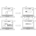
- FIG. 2D is a diagram illustrating an overview of inputting a subject as a central element in the user terminal 210 of the information processing system according to the present embodiment. There are, for example, the following two procedures for inputting the subject, but the procedure is not limited to these.
- the "ShareB application” is started (or when the browser connects to the ShareB server), a display screen 221 is displayed and the theme setting mode (central element setting mode) is entered.
- the "ShareB application” opens a subject input field in the center of the screen as shown in the display screen 222.
- the theme data is input by key on the display screen 222, the theme "Heliocentrism is correct! is confirmed and displayed as the theme, as shown in the display screen 224, and the screen changes to the element setting mode display screen.
- the input of the subject data is not limited to key input, and may also be input by copying a display sentence in another application.
- the other is the procedure from the display screen 223 to the display screen 224.
- the "ShareB application” is started (or when the browser connects to the ShareB server)
- a display screen 223 is displayed and the theme setting mode is entered.
- the theme setting mode is entered.
- you “drag and drop” a display sentence from another application onto a blank space on the display screen 223, the theme "Heliocentrism is correct!” will be confirmed and displayed as the display screen 224. Transition to the element setting mode display screen.
- FIG. 2E is a diagram illustrating an outline of input of peripheral element data in the user terminal 210 of the information processing system according to the present embodiment.
- peripheral element setting mode peripheral element setting mode
- the "ShareB application” opens input fields for peripheral elements around the subject as shown on the display screen 232.
- "Copernicus” is determined and displayed as the peripheral element, as shown in the display screen 234, and the display screen changes to a link setting mode display screen.
- the input of peripheral elements is not limited to key input, and may be input by copying or linking a display image (including a video) or a display sentence in another application.
- the other is the procedure from the display screen 233 to the display screen 234.
- the display screen 231 in the element setting mode for example, if you "drag and drop” a display image (including a video) or a display sentence in another application into a blank area of the display screen 233 in order to input a copy or link it, As shown in the display screen 234, "Copernicus” is determined and displayed as a peripheral element, and the display screen changes to a link setting mode display screen. Furthermore, by copying and inputting a web URL and "drag-and-dropping" it, the information of the link destination can be stored in the element.
- the degree of influence of "Copernicus” as a peripheral element on the theme as a central element is input from an influence input unit 236.
- the degree of this influence is expressed by the size, color, etc. of "Copernicus” as a peripheral element, and is stored in the database.
- FIG. 2F is a diagram showing an overview of link data input in the user terminal 210 of the information processing system according to this embodiment.
- the links include, for example, the following three links, but are not limited to these. Furthermore, the link input operations are not limited to these.
- a menu 245 is displayed that shows three types of links to connect.
- the subject "Heliocentrism is correct!” and the element "Copernicus” are connected by a link that has no causal relationship.
- a strength input section 246 for inputting the strength of the link is displayed on the display screen 242.
- the strength of the input link is represented by the thickness and color of the link and is stored in the database.
- FIG. 2G is a diagram illustrating an overview of a thought structure diagram registration request in the user terminal 210 of the information processing system according to the present embodiment.
- the upper diagram in FIG. 2G shows the disclosure range setting screen 251.
- a user who generates a thought structure diagram and requests registration selects one from three types of disclosure range selection menu 255.
- the three types of disclosure range are complete disclosure, limited disclosure, and private disclosure. If full disclosure is selected, it will be viewable to all users. If limited disclosure is selected, only the members designated by the creator of the thought structure diagram as designators can view it. Note that the members may be specified on an individual basis or on an attribute basis such as age. If private is selected, only the creator of the thought structure diagram can view it. Note that the disclosure range is not limited to these three types. For example, you may specify members who do not want to be made public with limited public access.
- FIG. 2G shows the editing authority setting screen 252.
- a user who generates a thought structure diagram and requests registration selects one from three types of editing authority selection menu 256.
- the three types of editing authority are full grant, limited grant, and no grant. If full grant is selected, full editing privileges are granted and peripheral elements (nodes), links, and central elements such as propositions and themes can be instantly added or deleted.
- the editing authority is not limited to the three types of editing authority illustrated here, and other editing authority may be provided.
- a user is basically given limited editing privileges between full editing privileges and limited editing privileges, but full editing privileges are granted only to users who have gained a lot of support in the past for limited editing. Possible settings include .
- a hidden parameter is set for each user, and the user's reliability as an editor is scored and stored, and the thought structure diagram generation user is given full editing authority or limited editing authority depending on the score. to be set. For example, settings such as "give full editing authority to people with a score of 500 or higher" are made.
- the creator of the thought structure diagram can set the granting of editing authority for each thought structure diagram. For example, it is possible to grant complete editing authority only to the creator (self) and not grant any editing authority to other users. On the other hand, it is also possible to set up a fair thinking structure diagram generation environment in which all users, including the creator, have limited editing authority. These editing authority grant settings are visible to all users. Furthermore, a function may be provided to set the thinking structure diagram so that it cannot be changed into an impossible structure by editing.
- the creator After setting the disclosure range and editing authority of the generated thought structure diagram, the creator registers the generated thought structure diagram in the information processing device (ShareB server) from the user terminal 210.
- the information processing device ShareB server
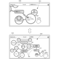
- FIG. 2H is a diagram showing an overview of editing instructions from the user terminal 220 of the information processing system according to this embodiment.
- the user terminal 220 is shown as a terminal that makes a thought structure diagram editing request and is different from the user terminal 210 of the thought structure diagram creator, it may be the same terminal.
- a process is being performed to restrict privileges. This is to prevent the original thought structure diagram from being changed into an impossible structure or deviating from the intention of the user who created it, if editing of the thought structure diagram is freely permitted.
- each user is given the option of editing ranked into three types as described above.
- a configuration is adopted in which privileges are granted in advance.
- a case will be described in which an attempt is made to add and edit a new element by double-clicking on the thought structure diagram on the display screen 261 of the element setting mode on the other user terminal 220.
- the editing authority is checked based on the user ID of the user using the user terminal 220, and if there is complete editing authority, an element column opens as shown in the display screen 262, and the screen changes to a display screen 263 in link setting mode. After that, a new element is added on the screen of the user terminal 220 and the thinking structure diagram is edited in the same manner as the operating procedure shown in FIGS. 2D and 2E.
- the user who generated the thought structure diagram can also check the settings (information) in the opened element column and restrict editing.
- the element or link that you attempt to add will be displayed as semi-transparent (indicated by a broken line in FIG. 2H), as shown in the display screen 265. Therefore, the addition of elements to the thought structure diagram is made to wait until the results of the user's approval vote are released. If the voting result is approved, the requested element is added as shown on the display screen 263. On the other hand, if the voting result is negative, the requested element disappears as shown on the display screen 266.
- FIG. 3A is a block diagram showing the configuration of an information processing system 300 according to this embodiment.
- the information processing system 300 includes a ShareB server 310 as an information processing device connected via a network 320, a user terminal 210 of a user who generates and posts thought structure diagrams, and publishes the thought structure diagrams, and the published thought structure diagrams. and a user terminal 220 of a user who shares and edits the same.
- the ShareB server 310 has a database 311, stores registered users and posted thought structure diagrams, and makes them publicly available for sharing.
- the user terminal 210 while communicating with the ShareB server 310, generates a thought structure diagram according to the operating procedures shown in FIGS. 2C to 2F and posts it to the ShareB server 310.
- the user terminal 220 views the thought structure diagram stored in the ShareB server 310 according to the operating procedure shown in FIG. 2G, and requests editing of the thought structure diagram if necessary.
- the user terminals 210 and 220 are depicted separately in FIG. 3A for convenience of explanation, the same user terminal may provide both functions.
- FIG. 3B is a sequence diagram showing the operation procedure of the information processing system 300 according to this embodiment.
- step S301 the ShareB server 310, the user terminal 210 (of the thought structure diagram generation user), and the user terminal 220 (of the thought structure diagram viewing user) become able to communicate by starting the ShareB application or by connecting with a browser. . Then, the ShareB server 310 and the user terminal 210 transition to the theme setting mode and wait for the setting of the theme as the central element.
- step S303 when a theme is input from the user terminal 210, in step S305, the ShareB server 310 acquires the theme and displays the theme in the center of the screen of the user terminal 210, and the ShareB server 310 and the user terminal 210 Transition to element setting mode and wait for peripheral element settings.
- step S307 when a peripheral element is input from the user terminal 210, in step S309, the ShareB server 310 acquires the element and displays the element around the subject on the screen of the user terminal 210, and the ShareB server 310 and the user terminal At step 210, the process transitions to link setting mode and waits for link setting.
- the ShareB server 310 acquires the link and creates a link between the subject and the elements or between the elements selected on the screen of the user terminal 210 in step S313. display.
- FIG. 3B shows a procedure for connecting elements with links each time they are added, the procedure is not limited to this, and may be a procedure of adding a plurality of elements and then connecting them together with links.
- a procedure may be provided to check the completion of the thought structure diagram. For example, if there is an element in the thought structure diagram that has no links connected to it, an error message will be displayed, and the user will still be able to link that element. If the element is not connected, the element may disappear when the thought structure diagram completion process is completed.
- the user of the user terminal 210 sets the disclosure range and editing authority and instructs posting (registration) of the thought structure diagram in step S315.
- the ShareB server 310 stores the thinking structure diagram posted from the user terminal 210 by setting the disclosure range and editing authority, and stores the thought structure diagram according to the disclosure range set on the user terminals 210 and 220. Publish. The published thinking structure diagram is viewed and shared at the user terminals 210 and 220. Note that when storing or viewing a thought structure diagram, the ShareB server 310 changes the arrangement of elements and links for thought structure diagrams that are difficult to see, such as links passing over elements or links crossing each other. automatically adjusts and rearranges it for easier viewing.
- processing for automatically adjusting the arrangement of elements and links and rearranging them for easier viewing may be performed while the thought structure diagram is being generated.
- the server may automatically prepare the size of peripheral elements, types of links, and peripheral elements themselves according to the theme. .
- step S321 when the user terminal 210 or 220 requests to edit (add or change) the thought structure diagram being viewed, the ShareB server 310 determines whether the user who requested the editing has full editing authority in step S323. , or check whether the editing authority rank is sufficient. If the user who requested editing has full editing authority or the rank of editing authority is sufficient, the ShareB server 310 allows editing (additions and changes) to the thought structure diagram in step S325, and displays the editing results. Instruct the display of a thought structure diagram. The user terminals 210 and 220 share the edited thought structure diagram in step S327.
- the ShareB server 310 notifies the user of no editing authority in step S331.
- the user terminal 220 notifies (warns) the user that he does not have editing authority.
- the ShareB server 310 requests the user terminal 220 (and the user terminal 210) to vote for approval of the edit in step S341.
- the user terminal 220 requests the user to vote for approval of the edit. If there is an approval vote, the user terminal 220 notifies the ShareB server 310 of the approval vote in step S345. Further, upon receiving a request for an approval vote, the user terminal 210 requests the user to vote for approval of the edit in step S347. If there is an approval vote, the user terminal 210 notifies the ShareB server 310 of the approval vote in step S349.
- the ShareB server 310 totals the approval votes from the user terminals 220 (and the user terminals 210) in step S351, and determines whether the edit is approved or rejected in step S353. Then, in step S355, the ShareB server 310 performs a process according to the determination result; if the edit is approved, the process is in step S325; if the edit is denied, the process is in step S331.
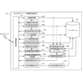
- FIG. 4 is a block diagram showing the functional configuration of the ShareB server 310 as an information processing device according to this embodiment.
- the ShareB server 310 includes a communication control section 401 , a subject acquisition section 402 , a theme display instruction section 412 , a peripheral element acquisition section 403 , a peripheral element display instruction section 413 , a link acquisition section 404 , and a link display instruction section 414 and a database 311.
- the ShareB server 310 also includes a thought structure diagram generation unit 405, a viewing request reception unit 406, a thought structure diagram publication unit 407, a thought structure diagram editing instruction reception unit 408, an editing authority confirmation unit 409, and an editing authority notification unit 405. 410, and a thought structure diagram registration portion 411.
- inputs to the subject display instruction section 412, peripheral element display instruction section 413, and link display instruction section 414 are simplified to avoid complexity.
- the ShareB server 310 also includes an approval vote aggregation unit 415 and an approval vote determination unit 416.
- the communication control unit 401 controls communication with the user terminals 210 and 220 via the network 320.
- the theme acquisition unit 402 acquires the theme transmitted from the user terminal 210 as a central element.
- the theme display instruction unit 412 instructs to display the acquired theme at a predetermined position (for example, the center of the screen) of the user terminal 210.
- the peripheral element acquisition unit 403 acquires peripheral elements transmitted from the user terminal 210.
- the peripheral element display instruction unit 413 instructs to display the acquired peripheral elements at a predetermined position (for example, around the subject) of the user terminal 210.
- the link acquisition unit 404 acquires the link transmitted from the user terminal 210 together with its type.
- the link display instruction unit 414 instructs to display the acquired link at a predetermined position on the user terminal 210 (for example, between a subject and a peripheral element, or between a peripheral element and a peripheral element) according to the type of the link.
- the database 311 stores data, parameters and programs necessary for processing by the ShareB server 310, and a thought structure diagram including a theme, peripheral elements, and links.
- the thought structure diagram generation unit 405 has a thought structure diagram generation table 451, and generates a thought structure diagram using the acquired or stored themes, peripheral elements, and links.
- the viewing request receiving unit 406 receives a request for viewing the thought structure diagram from the user terminal 220.
- the thought structure diagram publishing unit 407 publishes the thought structure diagram to the user terminals 210 and 220 in response to the thought structure diagram viewing request, taking into consideration the set disclosure range.
- the thought structure diagram publishing unit 407 has a publication restriction unit that restricts publication of the thought structure diagram by the thought structure diagram publication unit 407 based on information on the disclosure range.
- the thought structure diagram editing instruction receiving unit 408 receives thought structure diagram editing instructions from the user terminals 210 and 220.
- the editing authority confirmation unit 409 confirms the editing authority of the user who has instructed to edit the thought structure diagram.
- the editing authority confirmation unit 409 allows the user to edit the thought structure diagram if the user has been granted complete editing authority.
- the editing authority confirmation unit 409 sends the editing authority notification unit 410 to the editing authority notification unit 410. The user is notified from the user terminal 220 that there is no editing authority.
- the editing authority confirmation unit 409 causes the editing authority notification unit 410 to notify the user of an approval vote from the user terminal 220.
- Approval vote tallying unit 415 tallies approval votes from user terminals 220 (and user terminals 210) within a predetermined period of time.
- the approval vote determination unit 416 determines whether the edit requested from the user terminal 220 is approved or rejected based on the total of approval votes. If the approval vote determination unit 416 approves the editing, it instructs the thought structure diagram generation unit 405 to confirm the editing, and if it disapproves the editing, it instructs the editing to disappear.
- the database 5A and 5B are diagrams showing the configuration of the database 311 according to this embodiment.
- the database 311 stores data, parameters and programs necessary for processing by the ShareB server 310, and a thought structure diagram including themes, elements, and links.
- the database 311 includes a subject storage section 510, a peripheral element storage section 520, a link storage section 530, and a disclosure range/editing authority registration section 540.
- FIG. 5A shows data acquired from the user terminals 210 and 220, and basic stored data such as user registration is not shown in FIG. 5A.
- the theme storage unit 510 stores a theme 513 as a central element set on the user terminal 210 in association with the user ID 511 for generating the thought structure diagram and the terminal ID 512 of the user terminal 210.
- the theme 513 may include the position on the display screen where the theme is displayed.
- the peripheral element storage unit 520 stores the peripheral elements 523 set in the user terminal 210 and the theme 524 related to the peripheral elements 523 in association with the user ID 521 for generating the thought structure diagram and the terminal ID 522 of the user terminal 210. Store. Note that the peripheral element 523 may include a position on the display screen where the peripheral element is displayed.
- the link storage unit 530 stores a link 533 set on the user terminal 210, a subject 534 connected by the link 533, peripheral elements 535, and A peripheral element 536 and a link type 537 of the link 533 are stored.
- the link storage unit 530 also stores a subject 538 related to the link 533. Note that from the theme 534, peripheral elements 535, and peripheral elements 536, two connected by a link 533 are selected. Further, the link 533 may include the position on the display screen where the link is displayed, or the position of the link may be adjusted from two positions connected by the link 533.
- the disclosure range/editing authority registration unit 540 stores the presence or absence of editing authority 542, the rank of editing authority 543, and the disclosure range 544 in association with the user ID 541.
- the database 311 may store a threshold value to be compared with the editing authority rank 543 or an editing threshold value for each thought structure diagram.
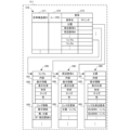
- FIG. 5B is a diagram showing the configuration of the thought structure diagram storage unit 570 stored in the database 311. Although FIG. 5B shows the configuration of one thought structure diagram, many registered thought structure diagrams are stored.
- the thought structure diagram storage unit 570 stores, in association with the thought structure diagram ID 571, the user ID 572 that registered this thought structure diagram and the elements 573 that constitute the thought structure diagram.
- the element 573 the subject of the element name, peripheral elements, links, and pointers to the theme data storage section 580, peripheral element data storage section 590, and link data storage section 500 representing the respective elements are stored.
- FIG. 5B if it is desired to maintain the history of editing processing, it is possible to record the edited user ID separately from the user ID registered in the user ID 572 corresponding to the element 573 of the editing result.
- the theme data storage unit 580 stores the theme content 581, display information 582, link destination peripheral elements 583, and the like.
- the display information 582 includes the display position, shape, size, color, etc. of the subject.
- the linked peripheral element 583 stores, for example, that it is connected to peripheral element A by link a, and that it is connected to peripheral element B by link b.
- the peripheral element data storage unit 590 (peripheral element A) stores the content 591, display information 592, link destination element 593, etc. of the peripheral element A.
- the display information 592 includes the display position, shape, size, color, etc. of the peripheral element A.
- the link destination element 593 stores, for example, that it is connected to the subject by a link a. Note that if there is a link with the peripheral element B, the peripheral element B and the link name are stored.
- the link data storage unit 500 (link a) stores the contents 501, display information 502, link information 503, etc. of link a.
- the display information 502 includes the display position, shape, size, color, etc. of link a.
- the link information 503 stores, for example, that this link represents a parent-child relationship, and that the direction is that the parent is the subject and the child is the peripheral element A. Note that if the link relationship is equal or conflicting, this is stored in the link information 503.
- FIG. 5C is a diagram showing the configuration of the thinking structure diagram generation table 451 according to this embodiment.
- the thought structure diagram generation table 451 is used when the thought structure diagram generation unit 405 generates a thought structure diagram using the acquired or stored theme as a central element, peripheral elements, and links.
- the thought structure diagram generation table 451 includes an attribute table 550 that shows the attributes of the generated thought structure diagram, and a configuration table 560 that shows the structure of the thought structure diagram.
- the attribute table 550 shows the thought structure diagram ID 553, the creation date 554, the set disclosure range 555, and the set editing authority in association with the user ID 551 that generated the thought structure diagram and the terminal ID 552 of the user terminal. 556 is stored.
- the configuration table 560 stores themes 562 and peripheral elements 563 associated with each theme 562 in association with the thought structure diagram ID 561.
- Theme 562 includes the content and display position of the theme.
- the peripheral element 563 includes the content of the peripheral element, the display position, the link with the subject and the type of link, and the link with other peripheral elements and the type of link.
- peripheral element 563 that is not linked to the theme 562, the "link to theme” and “link type” data are not significant. Furthermore, when one peripheral element 563 links to multiple themes 562, the same peripheral element has multiple “links with themes” and “link types.”
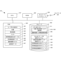
- FIG. 6 is a block diagram showing the hardware configuration of the ShareB server 310 according to this embodiment.
- a CPU (Central Processing Unit) 610 is a processor for arithmetic control, and implements the components shown in FIG. 4 by executing a program.
- a ROM (Read Only Memory) 620 stores fixed data and programs such as initial data and programs.
- Network interface 630 controls communication with user terminals 210 and 220 via network 320.
- a RAM (Random Access Memory) 640 is a random access memory that the CPU 610 uses as a temporary storage work area.
- the RAM 640 has an area reserved for storing data necessary to implement this embodiment.
- the user ID (terminal ID) 641 is the ID of the user or user terminal communicating with the ShareB server 310.
- the theme 642 is the data of the theme as a central element received from the user terminal.
- the peripheral element 643 is peripheral element data received from the user terminal.
- Link 644 is link data received from the user terminal.
- the thought structure diagram generation table 451 is a table used by the thought structure diagram generation unit 405 described in FIG. 6B to generate a thought structure diagram.
- the thought structure diagram data 645 is thought structure diagram data that is generated and shared with users.
- the editing authority comment 646 is a comment for notifying the user when the user does not have editing authority for the thought structure diagram or when the level of editing authority is low.
- the editing authority comments 646 also include comments requesting an editing approval vote.
- Transmission/reception data 647 is data transmitted/received to/from user terminals 210 and 220 via network 320.
- the storage 650 stores a database, various parameters, and the following data or programs necessary to implement this embodiment.
- the database 311 is a database that stores synthetic data, and includes storage units 510 to 530 for subjects/peripheral elements/links, and a disclosure range/editing authority registration unit 540, as shown in FIG. 5A.
- the ShareB server processing program 651 is a program that controls the entire ShareB server 310.
- the theme/peripheral element/link acquisition module 652 is a module that acquires the theme, peripheral elements, and link settings from the user terminal.
- the thought structure diagram generation module 653 is a module that generates a thought structure diagram using the acquired theme, peripheral elements, and links.
- the thought structure diagram sharing module 654 is a module that publishes the thought structure diagram in response to a viewing request from a user terminal and allows users to share the thought structure diagram, and also includes a process of determining the disclosure range.
- the thought structure diagram editing module 655 is a module for editing the thought structure diagram by the user, and also includes processing for determining editing authority.
- FIG. 7 is a flowchart showing the processing procedure of the ShareB server 310 according to this embodiment. Note that this flowchart is executed by the CPU 610 in FIG. 6 using the RAM 640 to realize the components in FIG. 4.
- step S711 the ShareB server 310 determines whether or not a thought structure diagram is to be generated. If the thought structure diagram is to be generated, a thought structure diagram generation process is executed in step S713.
- the ShareB server 310 determines in step S721 whether or not the thought structure diagram is to be viewed. If the viewing is a thought structure diagram, the ShareB server 310 determines in step S722 whether the viewing user has viewing authority. If there is no viewing authority, the ShareB server 310 notifies the viewing user that there is no viewing authority in step S724. If the ShareB server 310 has the viewing authority, in step S723, the ShareB server 310 acquires the corresponding thought structure diagram for which viewing is requested. Then, in step S725, the ShareB server 310 publishes the thought structure diagram as a thought structure diagram sharing process (sharing with terminals that have access rights).
- the ShareB server 310 determines in step S731 whether the purpose is to edit a thought structure diagram. If the edit is a thought structure diagram, the ShareB server 310 obtains the user ID of the user who requested the edit in step S733. Then, in step S735, the ShareB server 310 checks the editing authority for the thought structure diagram to be edited from the acquired user ID. In step S737, if the ShareB server 310 is granted full authority based on the editing authority check result, in step S739, the ShareB server 310 executes the thought structure diagram editing process and shares the editing result.
- the ShareB server 310 notifies the user from the user terminal that there is no editing authority in step S741. Furthermore, if limited editing authority is granted, the ShareB server 310 performs editing processing in step S743 based on the voting result for approval of editing. That is, if the voting result is approval for editing, the edited portion is determined. On the other hand, if the voting result is to reject the edit, the edited portion is deleted.
- FIG. 8 is a flowchart showing the procedure of thought structure diagram generation processing S713 according to this embodiment.
- step S801 the ShareB server 310 waits to receive a subject as a central element from the user terminal 210.
- the ShareB server 310 stores the received theme in the database 311 in step S803, and instructs it to be displayed at a predetermined position (eg, the center of the screen) on the display screen of the user terminal 210.
- step S805 the ShareB server 310 waits to receive peripheral elements from the user terminal 210.
- the ShareB server 310 stores the received peripheral element in the database 311 in step S807, and instructs it to be displayed at a predetermined position (for example, around the subject) on the display screen of the user terminal 210. do.
- step S809 the ShareB server 310 waits to receive a link from the user terminal 210.
- the ShareB server 310 stores the received link in the database 311 in step S811, and displays it at a predetermined position on the display screen of the user terminal 210 (for example, between the subject and peripheral elements, or between the peripheral elements). (between surrounding elements).
- FIG. 8 shows a procedure for connecting elements with links each time they are added, the procedure is not limited to this, and may be a procedure of adding a plurality of elements and then connecting them together with links.
- step S813 the ShareB server 310 determines whether the generation of the thought structure diagram is finished. If the generation of the thought structure diagram is not completed, the ShareB server 310 returns to step S801 and repeats the setting of peripheral elements and links in steps S805 to S811.
- the ShareB server 310 checks whether the thought structure diagram is complete or incomplete in step S815. For example, check to see if there are any unreasonable parts in the structure of the thought structure diagram (for example, whether there are any elements that are dangling with no links). Then, in step S817, the ShareB server 310 determines whether the thought structure diagram is incomplete. If it is incomplete, the process returns to step S801 and repeats the settings of the subject, peripheral elements, and links in steps S801 to S811.
- the ShareB server 310 receives the editing authority and disclosure range from the user terminal 210 and sets it in the generated thought structure diagram in step S819. Then, in step S821, the ShareB server 310 registers the thought structure diagram in which the editing authority and disclosure range have been set. Note that the ShareB server 310 may perform a process of rearranging elements, links, etc. in step S821 in order to make the thought structure diagram easier to see before registration.
- the editing authority and disclosure range are set when the thought structure diagram is complete, but they can be set or changed during the generation of the thought structure diagram, or after the thought structure diagram is generated. You can do it like this.
- FIG. 9 is a block diagram showing the functional configuration of the user terminals 210 and 220 according to this embodiment.
- the user terminal 210 includes a communication control unit 901 and an input/output interface 902.
- the communication control unit 901 controls communication with the ShareB server 310 via the network 320.
- a display section 921 and an operation section 922 are connected to the input/output interface 902.
- the display unit 921 displays a display screen when generating, viewing, or editing a thought structure diagram. Additionally, the status of the user terminal 210 is notified.
- the operation unit 922 also accepts user input and operations when generating, viewing, and editing a thought structure diagram. Note that in this embodiment, when a smartphone, a tablet, or the like is used as the user terminal 210, the display section 921 and the operation section 922 are integrated as a touch panel.
- the user terminal 210 also includes a theme acquisition section 903, a theme transmission section 904, a peripheral element acquisition section 905, a peripheral element transmission section 906, a link acquisition section 907, a link transmission section 908, and a thought structure diagram reception section. 909, and a thought structure diagram display instruction section 910. Note that in FIG. 9, functional units that instruct display of the subject, peripheral elements, and links on the display unit 921 are omitted in order to avoid complication of illustration.
- the user terminal 210 also includes an editing authority/disclosure range acquisition section 917 and a thought structure diagram registration requesting section 918.
- the theme acquisition unit 903 acquires the theme input from the operation unit 922 as the central element. Then, the theme transmitting unit 904 transmits the acquired theme to the ShareB server 310.
- the peripheral element acquisition unit 905 acquires peripheral elements input from the operation unit 922. Then, the peripheral element transmitting unit 906 transmits the acquired peripheral element to the ShareB server 310.
- the link acquisition unit 907 acquires the link input from the operation unit 922. The link transmitter 908 then transmits the acquired link to the ShareB server 310.
- the thought structure diagram receiving unit 909 receives the thought structure diagram that is being generated or has been generated from the ShareB server 310.
- the thought structure diagram display instruction section 910 instructs the display section 921 to display the received thought structure diagram.
- the thought structure diagram receiving section 909, the thought structure diagram display instruction section 910, and the display section 921 function as a central element display section, a peripheral element display section, and a link display section.
- the editing authority/disclosure range acquisition unit 917 acquires the editing authority and disclosure range of the generated thought structure diagram from the operation unit 922.
- the thought structure diagram registration requesting unit 918 sends the thought structure diagram in association with the acquired editing authority and disclosure range, and requests the ShareB server 310 to post (register) the thought structure diagram.
- the user terminal 210 includes a thought structure diagram viewing request acquisition unit 911 , a thought structure diagram viewing request unit 912 , a thought structure diagram editing instruction acquisition unit 913 , a thought structure diagram editing transmission unit 914 , and an editing authority receiving unit 915 and an editing authority notification section 916.
- the thought structure diagram viewing request acquisition unit 911 acquires a thought structure diagram viewing request through an operation from the operation unit 922 .
- the thought structure diagram viewing request unit 912 then transmits a viewing request to the ShareB server 310.
- the thought structure diagram corresponding to the viewing request is displayed on the display section 921 by the thought structure diagram receiving section 909 and the thought structure diagram display instruction section 910.
- the thought structure diagram editing instruction acquisition unit 913 acquires a thought structure diagram editing request through an operation from the operation unit 922 . Then, the thought structure diagram editing and sending unit 914 sends the editing request to the ShareB server 310.
- the editing authority receiving unit 915 receives a message indicating that there is no editing authority when the user's editing authority is not satisfied in response to a thought structure diagram editing request. Then, the editing authority notification unit 916 notifies the user from the display unit 921 that there is no editing authority.
- FIG. 10 is a flowchart showing the processing procedure of the user terminals 210 and 220 according to this embodiment. This flowchart is executed by the CPUs of the user terminals 210 and 220 using the RAM to realize the components of FIG.
- the user terminal 210 will be described below as a representative example.
- step S1011 the user terminal 210 determines whether or not a thought structure diagram is to be generated. If the thought structure diagram is to be generated, the user terminal 210 displays a thought structure diagram generation screen in step S1013 (see FIG. 2C). In step S1015, the user terminal 210 transmits the input subject to the ShareB server 310 and displays it on the display screen. In step S1017, the user terminal 210 transmits the input peripheral elements to the ShareB server 310 and displays them on the display screen. In step S1019, the user terminal 210 transmits the input link to the ShareB server 310 and displays it on the display screen. Note that although a procedure has been shown in which each additional peripheral element is connected with a link, the procedure is not limited to this, and the procedure may be such that after adding a plurality of peripheral elements, they are connected together with a link.
- step S1021 the user terminal 210 determines whether the generation of the thought structure diagram is complete based on the user's instruction. If the generation of the thought structure diagram is not completed, the user terminal 210 returns to step S1015 and repeats the input of the subject, element, and link in steps S1015, S1017, and S1019 until the generation of the thought structure diagram is completed.
- the user terminal 210 receives settings for editing authority and disclosure range in step S1023. Then, in step S1025, the user terminal 210 posts and saves the thought structure diagram with editing authority and disclosure range settings to the ShareB server 310 for sharing the thought structure diagram.
- the user terminal 210 determines in step S1031 whether or not the thought structure diagram is to be viewed. If the thought structure diagram is to be viewed, the user terminal 210 waits for a result from the ShareB server 310 as to whether or not the viewing authority is satisfied in step S1033. If viewing authority is granted, the user terminal 210 receives and displays the thought structure diagram to be viewed in step S1035. If the viewing authority is not granted, the user terminal 210 notifies the user that the viewing authority is not granted in step S1037. In step S1039, the user terminal 210 determines whether there is an instruction to edit the thought structure diagram. If there is no instruction to edit the thought structure diagram, the process ends.
- the user terminal 210 waits for a result from the ShareB server 310 as to whether the editing authority is satisfied in step S1041. If complete editing authority or limited editing authority has been granted, the user terminal 210 inputs editing of the thought structure diagram in step S1043. If there is no editing authority, the user terminal 210 notifies the user that there is no editing authority in step S1045.
- the user terminal 210 inputs the editing of the thought structure diagram in step S1039, and is notified from the ShareB server 310 that the inputted editing has become an approval vote, and selects whether to approve or disapprove. wait for something You can also vote for approval yourself. Since these processes wait for the result of the approval vote, they may be performed in parallel with the thought structure diagram generation process and the thought structure diagram viewing process, but are omitted in FIG. 10.
- the thought structure diagram can be easily generated on the user terminal 210 of the user who publishes the thought structure diagram, and can be shared with the user terminals 220 of other users.
- the information processing system according to this embodiment is different from the second embodiment in that the thought structure diagram is changed in response to the user's vote on the displayed themes and elements.
- the other configurations and operations are the same as those in the second embodiment, so the same configurations and operations are given the same reference numerals and detailed explanation thereof will be omitted.
- the following voting operation by the user is performed on a thought structure diagram generated and registered by the generating user, or on a thought structure diagram edited by the user after registration. May be done.
- a voting model of the thought structure diagram in which the element size, link strength, etc. are not set may be provided, and voting may be performed on the thought structure diagram voting model.
- the voting model of the thought structure diagram may be registered or edited by the user.
- FIG. 11A is a diagram showing voting operations of user terminals 1110 and 1120 in the information processing system according to this embodiment.
- the upper diagram in FIG. 11A shows a display screen 1111 of a thought structure diagram generated by the user on the user terminal 1110.
- a thought structure including a subject 212 as a central element, peripheral elements 213, and links 214 is displayed.
- a ring 1112 for displaying voting results by users is displayed around the peripheral element 213.
- the size of the peripheral elements 213 is not large or small (the importance is the same), and the voting results for both the theme 212 and the ring 1112 correspond to the theme support rate/theme rejection rate. No coloring has been done.
- the center diagram of FIG. 11A shows a state in which the user has selected "Eudoxos", which is the peripheral element 213, as a voting destination.
- a window 1101 for explaining Eudoxos opens, and along with the explanation of Eudoxos, it shows "supports the theme” (hereinafter referred to as “theme support”), “denies the theme” (hereinafter referred to as “theme negation”), and "appropriate for the theme”.
- a soft button will be displayed to vote for either “Not reliable” (or “Unreliable”: hereinafter referred to as "Inappropriate element”). Note that even when another peripheral element is selected as a voting destination, the same soft button is displayed along with an explanation of the peripheral element.
- the lower diagram in FIG. 11A shows a state in which the user has voted for "deny the subject.”
- the voting results are sent to the ShareB server 1210 and stored in the database 1211. Then, the display (size, shape, color, etc.) of the surrounding elements will be changed according to the accumulated voting results, and this will be reflected on other surrounding elements and themes associated with the surrounding elements via links, and will also be reflected in the links. .
- FIG. 11B is a diagram showing changes in the display screens 1111 of the user terminals 1110 and 1120 in the information processing system according to this embodiment, reflecting voting.
- FIG. 11B corresponds to FIG. 11A and shows a state in which voting by users has not yet been performed.
- the upper diagram in FIG. 11B is a display screen 1141 of a thought structure diagram when a vote is performed by the users and as a result of the voting, there are many votes in favor of the theme for peripheral elements of Copernicus.
- the inappropriate votes are subtracted from the total number of votes as the voting results of the theme 212 as the central element and the peripheral elements 213, such as supporting the theme, denying the theme, or inappropriate, from the users who viewed the thought structure diagram.
- the votes cast and the voting percentage (rate) are displayed.
- the size of each peripheral element 213 represents the total number of votes minus inappropriate votes.
- the peripheral element 213 of Copernicus which is large in size, has a large number of votes obtained by subtracting inappropriate votes from the total number of votes, indicating that it has a large influence on the theme 212.
- the peripheral element 213 of Regiomontanus which is small in size, has few votes, including support for the theme/denial of the theme, or many votes that the element is inappropriate, indicating that it has little influence on the theme 212.
- Other peripheral elements 213 also do not have many votes and are small in size.
- the percentage of votes for theme support (grid) 1113 and theme negation (halftone dots) 1114 is displayed in different colors, for example. (Different colors are indicated by different patterns).
- the percentage of votes for theme support 1113 and theme negation 1114 is displayed in a ring 1112 around an element figure (for example, a circle) in association with different colors of the theme.
- votes for each peripheral element 213 are reflected in the subject 212 and other peripheral elements 213 associated with the link 214. Whether or not to reflect votes between elements may be selected when setting the link 214 or the like.
- voting for the link 214 is easily visible and affects the thought structure diagram visually, it is desirable that its shape be determined according to surrounding elements. For example, when creating or editing a thought structure diagram, the user sets it to "Equal (rectangle ⁇ )," but as a result of subsequent voting, one of the two peripheral elements connected by a link supports the heliocentric theory. It is conceivable that if one vote results in one vote and the other vote results in "supporting geocentric theory", the shape of the link between them is automatically changed to a "confrontation (diamond ⁇ )" link. Note that the shape of the link 214 may be determined according to surrounding elements when setting the link 214, or the shape may be selected by the user who has set the link 214. Further, the influence of voting on the link 214 is not limited to the method of expressing it as an influence on opacity, but various display methods that can be considered include visual recognition such as the shape of the link or a broken line.
- the theme 212 has a high proportion of theme support 1113. Furthermore, the reason why there is a high percentage of theme support 1113 in theme 212 is due to Copernicus's positive interest in peripheral elements 213, and the voting results for other peripheral elements 213 do not have much influence on thoughts about theme 212. This can be understood by looking at the display screen 1141 at a glance. For example, the display screen 1141 well represents the thought structure after Newton on the theme of "Heliocentrism is correct!, and the current situation is that the number of supporters of the heliocentric theory is decreasing more and more. Be able to understand thoughts structurally.
- the lower part of FIG. 11B is a thought structure diagram display screen 1151 when users vote and as a result of the voting, there are many negative votes for the theme in peripheral elements of Eudoxus.
- the display screen 1151 displays inappropriate votes from the total number of votes as voting results such as support for the theme/denial of the theme/inappropriate elements for the theme 212 as the central element and the peripheral elements 213 from users who viewed the thought structure diagram.
- the subtracted votes and the percentage of votes supporting the theme/voting against the theme are displayed.
- the total number of votes minus inappropriate votes is represented by the size of each peripheral element 213.
- the peripheral element 213 of Eudoxos which is large in size, has many votes, including those supporting the theme/denying the theme, while there are few votes indicating that the element is inappropriate, indicating that it has a large influence on the theme 212.
- the peripheral element 213 of Copernicus which is small in size, there are few votes including support for the theme/denial of the theme, or there are many votes indicating that the element is inappropriate, which shows that the influence on the theme 212 is small. Note that even if the votes including support for the theme/denial of the theme are the same, the elements with many votes for element inappropriateness and elements with few votes are displayed in a distinguishable manner.
- the size of the peripheral element 213 of Eudoxus is large and the size of the peripheral element 213 of Copernicus is small, and as a result, it is shown that the theme 212 has fewer theme supports 1113 than theme negations 1114.
- this thought structure diagram may well represent the thought structure shared by many people. This means that it can be evaluated as being effective in generating thought structure diagrams in the future.
- voting on the theme 212 (or proposition) as a central element is a vote for or against, and voting for peripheral elements or links is not a vote for or against, but rather a vote for determining the attributes and importance of information. becomes. For example, if the user looks at the peripheral elements 213 of Copernicus and feels that "this peripheral element supports the heliocentric theory," he or she votes for "this peripheral element supports the heliocentric theory.” On the other hand, if you feel that ⁇ this peripheral element supports the geocentric theory,'' you will vote for ⁇ this peripheral element supports the geocentric theory.'' Depending on the ratio, the color, shape, etc.
- this peripheral element is reduced in size, and when it is reduced to the minimum size, its opacity is further reduced. The opacity then reaches its lowest level, and the element disappears after a certain period of time.
- the display method of ⁇ reducing the size'' or ⁇ lowering the opacity'' may be used. However, other display methods may be used.
- voting for a proposition (or theme) as a central element is each user's support for/denial of the theme, and the size of peripheral elements corresponding to the number of votes represents their importance in the thought structure diagram. It is. Changes in peripheral elements and links caused by such voting have the effect of making the thought structure for the central element shown in the thought structure diagram closer to a universal thought structure, making it easier to see and organized. Furthermore, changes in the thought structure diagram through voting allow the user to gain an intuitive understanding of the thought structure.
- FIG. 11C shows the display of the filtered thinking structure diagram on the user terminals 1110 and 1120.
- the display screen 1141 in the center diagram of FIG. 11C is similar to the top diagram of FIG. 11B.
- the voting results are filtered under various conditions on the thought structure diagram on the display screen 1141 that reflects the user's voting results.
- the top, bottom, left, and right diagrams in FIG. 11C show thought structure diagrams that have changed as a result of filtering using different conditions.
- the left and right display screens 1161 and 1181 in FIG. 11C are the results of filtering based on the nationality of the user who voted.
- the display screen 1161 on the left is a thought structure diagram in which votes of users having nationality of country A are searched and the voting results are reflected.
- the display screen 1181 on the right is a thought structure diagram in which votes of users having nationality of country B are searched and the voting results are reflected.
- the upper limit display screens 1171 and 1191 in FIG. 11C are the results of filtering based on the religion of the voting user.
- the upper display screen 1171 is a thinking structure diagram in which the votes of users who believe in religion a are searched and the voting results are reflected.
- the lower display screen 1191 is a thought structure diagram in which the votes of users who believe in religion b are searched and the voting results are reflected.
- Filtering conditions are not limited to other conditions related to user attributes (age, gender, etc.), but include all conditions necessary to analyze thought structures, such as voting period, voting time, and geographical conditions. .
- FIG. 12A is a block diagram showing the configuration of an information processing system 1200 according to this embodiment.
- the information processing system 1200 includes a user terminal 1120 that allows users to view the thought structure diagram and vote on its themes, peripheral elements, and links, and information that aggregates votes from the user terminal 1120 and reflects the results in the thought structure diagram.
- a ShareB server 1210 as a processing device is connected via a network 320.
- FIG. 12B is a sequence diagram showing the operation procedure of the information processing system 1200 according to this embodiment. Further, in FIG. 12B, editing of the thought structure diagram in FIG. 3B is omitted, but editing of the thought structure diagram is also included.
- step S1221 the user terminals 1110 and 1120 vote on the themes and elements of the thought structure diagram they are viewing.
- the ShareB server 1210 that has received the voting results totals the voting results for the theme, each peripheral element, and each link of each thought structure diagram in step S1223.
- step S1225 the ShareB server 1210 reflects the statistical values of the vote tally results (for example, the total number of votes and the proportion of support and denial) on the display of the theme, each peripheral element, and each link, and displays the results on the user terminal 1110. and send to 1120.
- User terminals 1110 and 1120 share the thought structure diagram in which the votes are reflected in step S1227.
- FIG. 12C is a sequence diagram showing the operation procedure of the information processing system according to this embodiment.
- FIG. 12C shows filtering processing of voting results.
- step S1231 the user terminal 1110 instructs the age of the user who voted as a filtering condition.
- step S1233 the ShareB server 1210 tabulates the voting results accumulated in the database by age group.
- step S1235 the ShareB server 1210 transmits the thought structure diagram to the user terminal 1110 with the age-specific statistical values reflected in the subject, peripheral elements, and links.
- the user terminal 1110 displays the received thinking structure diagram by age group in step S1237.
- step S1241 the user terminal 1120 specifies the religion of the user who voted as a filtering condition.
- the ShareB server 1210 tabulates the voting results accumulated in the database by religion (and by sect).
- step S1245 the ShareB server 1210 transmits the thought structure diagram to the user terminal 1120 with the statistical values for each religion reflected in the theme, peripheral elements, and links.
- step S1247 the user terminal 1120 displays the received thought structure diagram by religion.
- step S1251 the user terminal 1110 instructs the gender of the user who voted as a filtering condition.
- step S1253 the ShareB server 1210 aggregates the voting results accumulated in the database by gender.
- step S1255 the ShareB server 1210 transmits the thought structure diagram to the user terminal 1110 with the gender statistics reflected in the subject, peripheral elements, and links.
- step S1257 the user terminal 1110 displays a thought structure diagram that reflects the received gender voting results.
- FIG. 13 is a block diagram showing the functional configuration of the ShareB server 1210 as an information processing device according to this embodiment. Further, in FIG. 13, functional elements related to editing the thought structure diagram in FIG. 4 are omitted.
- the ShareB server 1210 includes a voting result acquisition unit 1307, a voting result aggregation unit 1308, a thinking structure diagram modification unit 1309, and a database 1211.
- the voting result acquisition unit 1307 acquires the voting results for the theme, each peripheral element, and each link of the thought structure diagram from the user terminal 1120.
- the voting results include the identifier of the user who voted (user ID), the identifier of the thought structure diagram (thought structure diagram ID), the identifier of the theme, each peripheral element, and each link (element ID), theme support/theme negation/inappropriate. Contains flags, etc.
- the voting result aggregation unit 1308 has a voting result aggregation table 1381, and calculates statistical values (total number, rate, etc.) by aggregating the obtained statistical results for each thought structure diagram, for each theme, peripheral elements, and links.
- the thought structure diagram modification unit 1309 has a thought structure diagram modification table 1391, and reflects the aggregated results in the generation of the thought structure diagram theme, each peripheral element, and each link by the thought structure diagram generation unit 405. That is, the total number of votes is represented by the size and opacity of surrounding elements, or by the color and opacity of links, etc., and the rate is represented by a distinguishable indication (for surrounding elements, by the length of the surrounding arc, etc.) (See Figures 11A-11C).
- the thought structure diagram publishing unit 407 also functions as a voting result display instruction unit that reflects the voting results when there is a vote.
- the ShareB server 1210 when performing filtering processing that changes the counting conditions of voting results during viewing, the ShareB server 1210 includes a condition acquisition unit that acquires filtering conditions for filtering voting results.
- the thought structure diagram modification unit 1309 functions as a filtering reflection unit that reflects the results of voting compiled in accordance with the filtering conditions on at least one display of the theme, peripheral elements, and links included in the thought structure diagram. do.
- FIG. 14A is a diagram showing the configuration of the database 1211 according to this embodiment.
- the database 1211 stores data, parameters and programs necessary for processing by the ShareB server 1210, and a thought structure diagram including a theme, peripheral elements, and links.
- the database 1211 includes a voting result storage section 1450 in addition to the subject storage section 510, peripheral element storage section 520, link storage section 530, and editing authority registration section 540 in FIG. 5A.
- Voting result storage section 1450 stores voting results from user terminals 1120 and their total results.
- the voting result storage unit 1450 stores a vote 1452 for the theme as a central element, a vote 1453 for peripheral elements, and a vote 1454 for a link in association with the thought structure diagram ID 1451.
- Voting for the theme 1452 includes, for example, the content of the theme, the number of votes for the theme, the number of negative votes for the theme, and the number of inappropriate votes for the theme.
- the voting for peripheral elements 1453 includes, for example, the content of the peripheral elements, the number of votes for the theme in the peripheral elements, the number of negative votes for the theme in the peripheral elements, and the peripheral elements. Including the number of inappropriate votes for the element.
- the vote for link 1454 includes, for example, the content of the link, the number of votes required for linking the link, the number of votes not requiring linking for the link, and the number of link type votes for the link, for example. .
- the configuration of voting result storage section 1450 is not limited to that shown in FIG. 14A. When one thought structure diagram has a plurality of themes, votes 1452 for the plurality of themes are stored in association with one thought structure diagram ID 1451.
- FIG. 14B is a diagram showing the configuration of the thought structure diagram storage unit 1470 stored in the database 1211 according to the present embodiment. Although FIG. 14B shows the configuration of one thought structure diagram, many registered thought structure diagrams are stored.
- the subject data storage unit 1410 stores voting results 1414 and voting result display information 1415.
- the voting result 1414 stores information regarding the theme support vote, information regarding the theme negative vote, and information regarding the theme inappropriate vote.
- the voting result display information 1415 stores, for example, information for displaying the area of the display shape of the theme in a color-coded manner into a theme support rate and a theme rejection rate.
- the peripheral element data storage unit 1420 stores element attributes 1424, voting results 1425, and voting result display information 1426.
- the element attribute 1424 is information indicating whether the voting results for the peripheral element A are reflected as they are or vice versa on, for example, a subject connected by a link. In the voting system of this embodiment, the "order relationship" is fixed, which is reflected as is.
- the voting result 1425 stores, for example, information regarding the theme support votes cast for peripheral element A, information regarding the theme negative votes, and information regarding the element inappropriate votes.
- the voting result display information 1426 stores, for example, information for displaying the periphery of the display shape of the peripheral element A (the circumference in the case of a circle) by color-coding the theme support rate and the theme rejection rate.
- the link data storage unit 1430 stores voting results 1434 and voting result display information 1435.
- the voting result 1434 stores, for example, information regarding votes requiring links, information regarding votes not requiring links, and information regarding votes for link types. Voting on link types includes, for example, parent-child relationship, equality, conflict, and the like. Note that a parent-child relationship, equality, conflict, etc. may be selected from the voting results for the elements connected by the link a.
- the voting result display information 1435 stores, for example, information such as the display shape, thickness, and opacity for displaying the link a.
- FIG. 14C is a diagram showing the configuration of the voting result aggregation table 1381 according to this embodiment.
- the voting result aggregation table 1381 is used by the voting result aggregation unit 1308 to aggregate the voting results obtained from the user terminals 1120.
- the voting result aggregation table 1381 stores a vote aggregation 1462 for the theme as a central element, a vote aggregation 1463 for peripheral elements, and a vote aggregation 1464 for links in association with the thought structure diagram ID 1461.
- the theme vote tally 1462 includes, for example, the content of the theme, the total number of votes for the theme, the number of inappropriate votes for the theme, the number of valid votes for the theme, the theme support voting rate, the theme negative voting rate, Remember.
- the number of valid votes for a subject is the number of votes obtained by subtracting the number of inappropriate votes for a subject from the total number of votes.
- the theme support voting rate is a value obtained by dividing the number of theme support votes for a theme by the number of valid theme votes.
- the theme negative voting rate is a value obtained by dividing the number of negative votes for a theme by the number of valid votes for the theme.
- the vote tally 1463 for peripheral elements includes, for example, the content of peripheral elements, the total number of votes for peripheral elements, the number of element inappropriate votes for peripheral elements, the number of element valid votes, the theme support voting rate, Memorize the theme negative voting rate.
- the number of element valid votes is the number of votes obtained by subtracting the number of element inappropriate votes from the total number of votes.
- the theme support voting rate is a value obtained by dividing the number of theme support votes in peripheral elements by the number of element valid votes.
- the theme negative voting rate is a value obtained by dividing the number of negative votes for the theme in peripheral elements by the number of valid votes for the element.
- the link vote tally 1464 includes, for example, the content of the link, the total number of votes for the link, the number of votes required for the link, the number of votes not required for the link, the required link voting rate, and the link type voting rate. , memorize.
- the required link voting rate is the value obtained by dividing the required number of votes for the link by the sum of the required number of votes and the unnecessary number of votes.
- the size and opacity of peripheral elements are determined based on the ratio between the "element valid votes” and “element inappropriate votes” and the difference in the number of votes. Further, the opacity of the link is determined by the link required voting rate. Note that the configuration of the voting result summary table 1381 is not limited to that shown in FIG. 14C. If one thought structure diagram has a plurality of themes, the vote tally 1462 of the plurality of themes is stored in association with one thought structure diagram ID 1461.
- votes for peripheral elements may be reflected in votes for the themes and other peripheral elements associated with links. Furthermore, it may be reflected in the voting of links connected to peripheral elements. For example, if a surrounding element receives many "inappropriate" votes and affects the opacity of the surrounding element, the opacity of the link connected to it will also decrease. Alternatively, if the voting results of one of two peripheral elements connected by a link conflict with the voting results of the other, the link is changed to a shape or color that represents the conflict.
- FIG. 14D is a diagram showing the configuration of the thought structure diagram correction table 1391 according to this embodiment.
- the thought structure diagram modification table 1391 is used by the thought structure diagram modification unit 1309 to modify the thought structure diagram in response to the tally of voting results.
- the thought structure diagram modification table 1391 stores display information 1472 for the theme, display information 1473 for peripheral elements, and display information 1474 for links in association with the thought structure diagram ID 1471.
- the display information 1472 for the theme includes, for example, the content of the theme, (the number of valid votes for the theme - the number of inappropriate votes for the theme), the display size of the theme, the theme support voting rate, the display size of the theme support rate, and the theme.
- the negative voting rate and the display size of the subject negative rate are stored.
- the display size of the theme does not change in FIGS. 11A to 11C, for example, if there are multiple themes in the thought structure diagram, it is desirable to change the display size of the theme.
- the change is not limited to the display size, and other visible expression methods such as opacity may be used.
- the display size of the theme support rate and the display size of the theme rejection rate are expressed as the area ratio within the display size of the theme that does not change in FIGS. 11A to 11C.
- the display information 1473 for peripheral elements includes, for example, the contents of the peripheral elements, (number of valid votes for the element - number of inappropriate votes for the element), display size and opacity of the peripheral elements, etc., for a plurality of peripheral elements.
- the theme support voting rate, the display size of the theme support rate, the theme negative vote rate, and the display size of the theme negative rate are stored.
- the display size of the surrounding elements changes depending on the size of the circle (number of valid votes for the element - number of inappropriate votes for the element), and the opacity of the surrounding elements changes to the minimum circle. After that, it becomes transparent (not shown).
- the expression method is not limited to the display size and opacity of peripheral elements, and other visually recognizable expression techniques may be used.
- the display size of the theme support rate and the display size of the theme rejection rate in peripheral elements are expressed by the ratio of the length of each color of the arc around the circle in FIGS. 11A to 11C. In 11C, different colors are indicated by different patterns).
- the display size is not limited to the ratio of the lengths of the respective colors of the arcs around the circle, and other visible representation techniques may be used.
- the color of the link display information 1474 changes depending on the voting results of surrounding elements, and the required voting rate and (required number of votes - number of unnecessary votes) are expressed by opacity and shape.
- the link shape selection may be determined by voting. For example, in voting, a method may be adopted in which the viewing user is allowed to choose from the following options: "No causal relationship/equal ⁇ ", "Parent-child ⁇ ", and "Conflict ⁇ ", and directly vote for each link.
- FIG. 14E is a diagram showing the configuration of the database 1211 when performing the filtering processing shown in FIGS. 11C and 12C. Note that the configuration of the database 1211 is not limited to that shown in FIG. 14E.
- the database 1211 in FIG. 14E includes a filtering storage section 1480 in addition to the subject storage section 510, peripheral element storage section 520, link storage section 530, editing authority registration section 540, and voting result storage section 1450 in FIG. 14A.
- the filtering storage unit 1480 stores a user ID (voting source) 1482 that voted for this thought structure diagram, user attributes 1483 as filtering conditions, voting period 1484, etc., and voting results in association with the thought structure diagram ID 1481.
- a vote 1485 for the theme, a vote 1486 for peripheral elements, and a vote 1487 for the link are stored.
- the configuration of the filtering storage section 1480 is not limited to that shown in FIG. 14E. For example, in order to maintain voting fairness, filtering can be performed to invalidate duplicate votes from the same user terminal.
- filtering conditions When filtering conditions are set, user attributes 1483, voting period 1484, etc. are searched using the filtering conditions as a search key to collect voting contents that match the filtering conditions. Then, the thought structure diagram is changed according to the collected contents.
- FIG. 14F is a diagram showing the configuration of a voting result aggregation table 1381 that collects voting contents that match the filtering conditions. During filtering, FIG. 14C is replaced by FIG. 14F.
- the thought structure diagram modification unit 1309 refers to the voting result aggregation table 1381 and changes the thought structure diagram using the thought structure diagram modification table 1391.
- the voting result aggregation table 1381 stores collection instructions 1491 and collection targets 1492 in association with thought structure diagram ID 1461. This collection instruction 1491 and/or collection target 1492 corresponds to filtering conditions. The votes collected based on each filtering condition have the same configuration as in FIG. 14C.
- FIG. 15A is a flowchart showing the processing procedure of the ShareB server 1210 of this embodiment. Further, this flowchart is executed by the CPU 610 in FIG. 6 using the RAM 640 to implement the components in FIG. 13.
- the ShareB server 1210 determines whether to perform filtered aggregation (if there is a request from the user terminal) in step S1519. If filtered aggregation is to be performed, the ShareB server 1210 proceeds to step S1591 in FIG. 15D.
- the ShareB server 1210 determines in step S1511 whether or not to obtain voting results from the user terminal 1120. If the voting results are obtained, the ShareB server 1210 executes aggregation processing of the obtained voting results in step S1513. In step S1515, the ShareB server 1210 executes a process of reflecting the voting results on the thinking structure diagram. Then, in step S1517, the ShareB server 1210 performs a process of sharing the thought structure diagram after reflection (sharing with a terminal that has access rights).
- FIG. 15B is a flowchart illustrating the procedure of vote result aggregation processing S1513 according to the present embodiment.
- step S1520 the ShareB server 1210 acquires the thought structure diagram ID of the voting target included in the voting information acquired from the user terminal 1120.
- step S1521 the ShareB server 1210 determines whether the voting target is a subject as a central element. If the voting target is a theme, the ShareB server 1210 adds 1 to the total number of votes for the theme in step S1523.
- the ShareB server 1210 determines whether the voting target is a peripheral element in step S1541. If the voting target is a peripheral element, the ShareB server 1210 adds 1 to the total number of votes for the target element in step S1543. Next, in step S1545, the ShareB server 1210 performs the same processing as the processing in steps S1525 to S1537 for the subject on the peripheral elements. Then, in step S1547, the ShareB server 1210 performs a process of reflecting the voting results for peripheral elements on the subject, other peripheral elements, links, and the like. Furthermore, if the voting target is neither the theme nor the peripheral elements, the ShareB server 1210 determines whether the voting target is a link in step S1551.
- the ShareB server 1210 adds 1 to the total number of votes for the target link in step S1553.
- the ShareB server 1210 performs the same processing on the link as the processing in steps S1525 to S1537 for the subject.
- voting may be performed to select a link shape such as "parent-child ⁇ ", “equal ⁇ ", "conflict ⁇ ", etc.
- the ShareB server 1210 may perform a process of reflecting the voting results for the link on the subject, peripheral elements, or other links in step S1557. Further, in the reflection process, it may be determined whether or not to be reflected when a thought structure diagram is generated or when an existing thought structure diagram is edited.
- a data reflection process may be added that reflects the voting results for a theme on other themes, peripheral elements, or links.
- FIG. 15C is a flowchart showing the procedure of the reflection process S1515 on the thinking structure diagram according to this embodiment.
- step S1561 the ShareB server 1210 determines whether the vote is to be reflected in the display of the theme. If there are votes for the theme and they are to be reflected in the display of the theme, the ShareB server 1210 obtains the total number of valid votes or valid voting rate for the theme in step S1562. Then, in step S1563, the ShareB server 1210 sets the display size of the subject corresponding to the total number of valid votes or the valid voting rate. In step S1564, the ShareB server 1210 obtains the theme support voting rate and the theme negative voting rate for the theme. Then, in step S1565, the ShareB server 1210 sets the display size of the theme support rate and the display size of the theme rejection rate for the theme.
- step S1566 the ShareB server 1210 modifies the display size of the theme (no modification in this example), modifies the display size of the theme support rate and the display size of the theme denial rate, and generates a theme display image.
- steps S1562 to S1566 if the voting results are reflected in the theme display using something other than size, other visible display changes may be set.
- the ShareB server 1210 determines in step S1571 whether the vote is for a peripheral element and the vote is to be reflected in the display of the peripheral element. When reflecting this in the display of peripheral elements, the ShareB server 1210 acquires the total number of valid votes or valid voting rate for the target element in step S1572. Then, in step S1573, the ShareB server 1210 sets the display size or opacity of the target element corresponding to the total number of valid votes or the valid voting rate. In step S1574, the ShareB server 1210 obtains the theme support voting rate and theme negative voting rate in the target element.
- step S1575 the ShareB server 1210 sets the display size of the theme support rate and the display size of the theme rejection rate in the target element.
- step S1576 the ShareB server 1210 corrects the display size of the target element, corrects the display size of the theme support rate and the display size of the theme rejection rate of the target element, and generates a display image of the target element. Note that in steps S1572 to S1576, if the reflection of the voting results on the display of peripheral elements is expressed using other than size or opacity, other visible display changes may be set.
- the ShareB server 1210 determines in step S1581 whether the vote is for a link and the vote is to be reflected in the display of the link. When reflecting this in the display of the link, the ShareB server 1210 acquires the required voting rate or unnecessary voting rate for the link in step S1582. Then, in step S1583, the ShareB server 1210 sets the display opacity of the target link corresponding to the total number of valid votes or the valid voting rate. Note that if the reflection of the voting results on the link display is expressed using something other than opacity, other visible changes in the display may be used. In step S1584, the ShareB server 1210 acquires the shape and color as the type of the target link.
- the ShareB server 1210 sets a color for the target link in step S1585.
- the ShareB server 1210 obtains the theme support voting rate and theme negative voting rate of the target peripheral elements to which the target link connects, and in step S1585, the ShareB server 1210 acquires the theme support voting rate and theme negative voting rate of the target peripheral elements.
- the color of the target link may be set based on the .
- the shape of the link is set in accordance with the voting result for the shape of the target link or the voting result for the elements connected by the target link.
- FIG. 15D is a flowchart showing the processing procedure of filtering processing when YES in step S1519 of FIG. 15A.
- step S1591 the ShareB server 1210 waits to receive filter conditions set from the user terminals 1110 and 1120 for filtering processing. Upon receiving the filter conditions, the ShareB server 1210 stores the received filter conditions in step S1593. In step S1595, the ShareB server 1210 searches the database 1211 for votes that match the filter conditions and collects them. Then, in step S1513, the ShareB server 1210 executes the vote aggregation process shown in FIG. 15B for the votes that match the filter conditions. Next, in step S1515, the ShareB server 1210 executes a process of reflecting the votes that meet the filter conditions on the thinking structure diagram shown in FIG. 15C using the results of the tally of votes that meet the filter conditions.
- FIG. 16 is a block diagram showing the functional configuration of user terminals 1110 and 1120 according to this embodiment. Furthermore, since the user terminals 1110 and 1120 have similar functions, the user terminal 1110 will be described as a representative. Further, in FIG. 16, functions related to editing the thought structure diagram in FIG. 9 are omitted.
- the user terminal 1110 includes a voting content acquisition section 1613 and a voting content transmission section 1614.
- the voting content acquisition unit 1613 acquires voting content for the subject, each peripheral element, each link, etc. input by the user from the operation unit 922.
- the voting content transmitting unit 1614 transmits information including the user ID, the thought structure diagram ID being viewed, the subject ID of the voting target, peripheral element ID of the voting target, link ID of the voting target, voting content, etc. to the ShareB server 1210. do.
- FIG. 17 is a flowchart showing the processing procedure of the user terminals 1110 and 1120 according to this embodiment. Note that in FIG. 17, instructions for editing the thought structure diagram of FIG. 10 are omitted.
- step S1745 the user terminal 1110 determines whether a filtering condition has been input. If the filtering conditions have been input, the user terminal 1110 receives and displays the thought structure diagram of the filtering results from the ShareB server 1210 in step S1747. If no filtering conditions are input, the user terminal 1110 proceeds to step S1737.
- step S1737 the user terminal 1110 determines whether the input is a vote input. If it is a vote input, the user terminal 1110 acquires the voting contents in step S1739, and transmits the voting target (thought structure diagram ID, theme ID, peripheral element ID, link ID, etc.) and the voting contents to the ShareB server 1210. do. Then, in step S1741, the user terminal 1110 waits for a response in which the vote is reflected in the thought structure diagram being viewed, and when there is a response, in step S1743, the user terminal 1110 receives and displays the thought structure diagram in which the vote is reflected. .
- FIG. 17 shows the operation of the user terminal that voted, steps S1741 and S1743 are processed separately following step S1747 to reflect the action on the thought structure diagram on a user terminal different from the user terminal that voted. This can be achieved by doing.
- voting in order to avoid biased voting results due to the same user voting in large numbers or many people voting in the same group, duplicate votes from the same user or the same group should be avoided. It is desirable to prohibit such voting or to control it by setting an upper limit on the number of votes. On the other hand, such restrictions can also be lifted in order to get more votes.
- voting control with the disclosure range, editing range, etc., it is possible to generate a thought structure diagram that more fairly reflects the user's intentions. Further, voting for the first peripheral element or the second peripheral element does not necessarily affect the central element voting result. In other words, it is possible to set a voting for a certain peripheral element to affect other peripheral elements connected by a link.
- the voting results for the first peripheral element or the second peripheral element are used independently to organize the direction of information on the first peripheral element or the second peripheral element, and the results are used as the central element voting results. It is also possible to consider a configuration that does not affect the These settings can be arbitrarily switched by the user who generated the thought structure diagram or the user who views and edits the thought structure diagram when generating, editing, or viewing the thought structure diagram.
- filtering for example, changing the ratio of pros and cons of a central element, the size and opacity of peripheral elements, the shape and thickness of links, and filtering information that affects these can be done by, for example, voting from the same user terminal. This may be done by invalidation, gender, place of birth, etc.
- a filtering function may be provided when displaying the thought structure diagram.
- the user's attributes can be referenced to determine whether or not the filtering function is implemented, the contents of the filtering function, or filtering for the viewing user who is the target of filtering. You can also switch.
- the filtering function re-aggregates votes for each peripheral element, theme, proposition, etc. based on each user's attributes such as ⁇ voter's gender'', ⁇ voter's place of birth'', and ⁇ voter's age'' and displays it on the screen. reflect this in the thinking structure diagram.
- the voting results for the themes and elements by the users are reflected in the thought structure diagram, so it is possible to obtain a universal thought structure diagram that is not extremely biased. Furthermore, since the voting results of many users are reflected in the structure of the thought structure diagram, there is also the effect of forming collective knowledge and sharing logical thinking circuits among many users. As a result, fairer and more accurate collective knowledge can be formed.
- FIG. 18 is a diagram showing a display screen 1811 of the user terminal 1810 in the information processing system according to this embodiment.
- a user comment field 1812 for the thought structure diagram displayed for viewing is displayed on the display screen (canvas) 1811 of the user terminal 1810.
- the comments and users in the comment field are displayed so that it can be seen whether each user in the comment field has voted for or against the proposition or theme that is the central element.
- Colors corresponding to the pros and cons are applied around the names and on the background.
- the comment may be associated and reflected as a vote (on the user's subject) in an element linked to the comment in the comment field.
- the comment field 1812 may be integrated with the thought structure diagram, or may be a comment posted independently from the thought structure diagram, for example, via SNS. However, it is preferable that each comment in the comment field be displayed in such a way that the theme of the thought structure diagram being viewed and its association with each element are clear. In addition, comments in the comment field can be tagged or associated according to the central element and peripheral elements, and when you hover over a comment, the corresponding central element, peripheral elements, links, etc. are highlighted. be done. Note that it is also possible to reply to existing comments, and in that case, the parent-child relationship of the comments is displayed for easy viewing.
- media and URL links are attached with buttons that allow them to be incorporated into the thinking structure diagram as new peripheral elements (or central elements) with one click (one tap). Comments are linked to each object (center element, peripheral element, link, etc.) (selected from the pull-down menu 1813), and when you mouse over each corresponding object in the display screen 1811, the comment is linked to that object at the same time. Comments (threads) that have been added are highlighted. The same process occurs in the opposite direction.
- a dedicated tag (channel) may exist for each link, or a comment for a link can be made by selecting both tags (channels) corresponding to the two elements located at both ends of the link. May be substituted. You can also add new tags (channels) to reply comments by associating them with other elements or links. User comments may be processed using LLM (Large-Scale Language Model) and treated as votes for each element.
- LLM Large-Scale Language Model
- N nodes peripheral elements
- N+1 tags or channels
- Select (channel) and comment are used when commenting on the subject/proposition itself in general.
- M the number of themes/propositions
- N+M tags are required. It is possible to select multiple tags (channels), but when replying to an existing comment, the tag (channel) of the reply destination comment (parent comment) will be forcibly added to the reply comment (child comment). be done. For example, when you want to mention the relevance of multiple peripheral elements, multiple tags are set for one comment.
- an information correlation diagram representing the comments is generated, including at least two graphical elements (central element and peripheral elements) that clearly represent the difference in the importance of information. You may. Then, in order to convey the comment to other users, an instruction may be given to display the information correlation diagram on a user terminal operated by another user.
- FIG. 19 is a block diagram showing the functional configuration of the ShareB server 1910 as an information processing device according to this embodiment. Further, in FIG. 19, functional elements related to editing the thinking structure diagram in FIG. 4 and functional elements related to voting in FIG. 13 are omitted.
- the ShareB server 1910 includes a comment acquisition unit 1908, a comment display instruction unit 1909, and a database 1911.
- the comment acquisition unit 1908 acquires comments from the user terminal 1120 on the thought structure diagram or on the theme, each peripheral element, and each link.
- a comment includes the identifier of the user who commented (user ID), the identifier of the thought structure diagram (thought structure diagram ID), the identifier of the subject and each peripheral element, the identifier of each link (element ID), the comment content, etc.
- the comment display instruction unit 1909 has a comment display table 1991, and connects the acquired comments with the generation of the theme, each peripheral element, and each link of the thought structure diagram by the thought structure diagram generation unit 405, and Reflect in the generation of elements and each link.
- FIG. 20A is a diagram showing the configuration of the database 1911 according to this embodiment.
- the database 1911 stores data, parameters and programs necessary for processing by the ShareB server 1910, and a thought structure diagram including a theme as a central element, peripheral elements, and links.
- the database 1911 includes a comment storage section 2060 in addition to a subject storage section 510, a peripheral element storage section 520, a link storage section 530, an editing authority registration section 540, and a voting result storage section 1450.
- the comment storage unit 2060 collects and stores comments input from the user terminals 1810 and 1820.
- the comment storage unit 2060 stores a timestamp 2062 at which the comment was input and a user ID 2063 who input the comment in association with the comment ID 2061. Then, the thought structure diagram ID 2064 targeted by the comment, the targeted theme 2065, the targeted peripheral elements 2066, the targeted link 2067, the comment content 2068, and the voting content 2069 if there is a vote from the comment section. , memorize.
- comment content 2068 may be a pointer to the comment content.
- the comment content 2068 includes linked external sites (news sites, Wikipedia (registered trademark), SNS, etc.), media such as images, videos, audio (uploaded from the user's PC, links from the Internet, etc.) (including both).
- items of the same type and content as those that can be posted on Twitter (registered trademark), or other media can be posted as comments.
- the configuration of comment storage section 2060 is not limited to that shown in FIG. 20A.
- FIG. 20B is a diagram showing the configuration of the thought structure diagram storage unit 1470 and the comment storage unit 2070 stored in the database 1911 according to the present embodiment. Although FIG. 20B shows the configuration of one thought structure diagram, many registered thought structure diagrams are stored.
- the user input comments stored in the comment storage section 2070 are linked to the theme, peripheral elements, and links in the thought structure diagram storage section 1470.
- the comment storage unit 2070 stores identification marks 2071 that identify peripheral elements and links targeted by the comment (if there are multiple themes, the identification marks of the themes are also stored).
- parameters of a plurality of displayed comments are stored corresponding to the subject or each peripheral element/link. Comment parameters include timestamps 2072 arranged in chronological order, user ID and terminal ID 2073, comment content 2074, link destination 2075 to comment content, and type of support/denial/inappropriateness associated with the comment. 2076, etc. are stored. Note that the configuration of comment storage unit 2070 is not limited to that shown in FIG. 20B.
- FIG. 20C is a diagram showing the configuration of the comment display table 1991 according to this embodiment.
- the comment display table 1991 is used to display comments obtained by the comment display instruction unit 1909 from the user terminals 1810 and 1820 together with the thought structure diagram. Note that FIG. 20C shows a case where there is one theme in the thought structure diagram, but the present invention is not limited to this. Further, the configuration of the comment display table 1991 is not limited to that shown in FIG. 20C.
- the comment display table 1991 stores a plurality of peripheral elements/links 2083 and an identification mark 2084 that identifies the peripheral elements and links targeted by the comment, in association with the thought structure diagram ID 2081 and its subject 2082. Then, parameters of a plurality of displayed comments are stored corresponding to the theme 2082 or each peripheral element/link 2083. Comment parameters include timestamps 2085 arranged in chronological order, user ID and terminal ID 2086, comment content 2087, link destination to comment content 2088, and type of support/denial/inappropriateness associated with the comment. 2089 is stored.
- 21A and 21B are flowcharts showing the processing procedure of the ShareB server 1910 according to this embodiment. Further, this flowchart is executed by the CPU 610 in FIG. 6 using the RAM 640 to implement the components in FIG. 19.
- step S2111 the ShareB server 1910 determines whether a comment is acquired from the user terminal 1810. If a comment is to be obtained, the ShareB server 1910 obtains the user ID (terminal ID) that made the comment in step S2113. In step S2115, the ShareB server 1910 acquires the thought structure diagram, theme, peripheral elements, and links of the comment target. In step S2117, the ShareB server 1910 inserts the comment content into the comment list in association with the thought structure diagram, theme, peripheral elements, and links of the comment target. Then, in step S2119, the ShareB server 1910 updates the comment field of the target thought structure diagram and displays it on the user terminals 1810, 1820 together with the thought structure diagram. In step S2120, the ShareB server 1910 determines whether to obtain votes from the comment column. If it is determined that the vote is to be obtained, the ShareB server 1910 proceeds to step S2121 in FIG. 21B.
- the ShareB server 1910 determines in step S2121 whether the vote is from the voting window in the comment section. If the vote is from the voting window, the ShareB server 1910 acquires the voting details in step S2123. Note that the voting window may be similar to the third embodiment (such as FIG. 11A), the sixth embodiment (such as FIG. 25A), and the seventh embodiment (such as FIG. 27A), or may be similar to that of the third embodiment (such as FIG. 11A), the sixth embodiment (such as FIG. Other formats are also possible.
- the ShareB server 1910 reflects the voting contents in the database 1911 in correspondence with the thought structure diagram, theme, peripheral elements, and links. Then, in step S2127, the ShareB server 1910 generates the thought structure diagram updated by voting and instructs to display it.
- the ShareB server 1910 analyzes the comments in the comment field and determines whether to vote in step S2131.
- the ShareB server 1910 acquires the target comment in step S2133.
- the ShareB server 1910 analyzes whether there is a voting content corresponding to the comment. Note that the analysis of the voting contents corresponding to the comments is performed by document recognition, etc., but a detailed explanation will be omitted here.
- step S2137 the ShareB server 1910 determines whether or not there is voting content, and if there is voting content, the process proceeds to step S2125, in which the voting content is processed in correspondence with the thought structure diagram, theme, peripheral elements, and links. , reflected in the database 1911.
- FIG. 22 is a block diagram showing the functional configuration of user terminals 1810 and 1820 according to this embodiment. Furthermore, since the user terminals 1810 and 1820 have similar functions, the user terminal 1810 will be explained as a representative. Further, in FIG. 22, functions related to editing the thought structure diagram in FIG. 9 and functions related to voting on the theme and peripheral elements in FIG. 16 are omitted.
- the user terminal 1810 includes a comment acquisition section 2213, a comment transmission section 2214, a comment field reception section 2215, and a comment field display instruction section 2216.
- the comment acquisition unit 2213 acquires comments input from the operation unit 922 for the thought structure diagram being viewed.
- the comment transmitter 2214 adds the user ID of the user who entered the comment, the thought structure diagram ID of the comment target, the subject ID, the peripheral element ID, etc. to the acquired comment content, and transmits the result to the ShareB server 1910.
- the comment field receiving unit 2215 receives the updated comment field corresponding to the thought structure diagram being viewed from the ShareB server 1910.
- the comment column display instruction section 2216 causes the display section 921 to display a comment column associated with the thought structure diagram being viewed.
- FIG. 23 is a flowchart showing the processing procedure of the user terminals 1810 and 1820 according to this embodiment. Note that in FIG. 23, the instruction to edit the thinking structure diagram in FIG. 10 and the voting input in FIG. 17 are omitted.
- step S2337 the user terminal 1810 determines whether or not it is a comment input. If it is a comment input, the user terminal 1810 acquires the comment content and transmits the comment target (thought structure diagram ID, theme ID, peripheral element ID, etc.) and the comment content to the ShareB server 1910 in step S2339. Then, in step S2341, the user terminal 1810 waits for a response in which the comment is reflected in the comment column corresponding to the thought structure diagram being viewed, and when there is a response, in step S2343, the user terminal 1810 receives the comment column in which the comment is reflected. and display it.
- FIG. 23 shows the operation of the user terminal that made the comment, reflection in the comment field on a user terminal different from the user terminal that made the comment is processed separately in steps S2341 and S2343 following step S1035. This can be achieved by
- peripheral elements can be generated from links, images, etc. attached to the comment field, and added and displayed as new elements in the thought structure diagram. In this case as well, it is desirable that editing authority be taken into account.
- the comment field may include a button that can be added to the thought structure diagram as a new peripheral element (or central element).
- the information processing system according to this embodiment differs from the second to fourth embodiments in that voting for a proposition as a subject is divided into three. Note that instead of three branches, there are four branches, five branches, etc., and there is no particular limit to the number of branches.
- the other configurations and operations are the same as those in the second embodiment, so the same configurations and operations are given the same reference numerals and detailed explanation thereof will be omitted.
- FIG. 24A is a diagram showing a display screen 2411 of the user terminal 2410 in the information processing system according to this embodiment.
- the theme 2412 has three options. The three options are associated based on the content of each element. Note that the number of options is not limited and may exceed three, as long as the options do not become so complicated that it becomes impossible for the user to understand the thought structure. Furthermore, when editing the thought structure diagram, it is also possible to add options from the contents of the thought structure diagram if necessary.
- FIG. 24B is a diagram showing another display screen 2421 of the user terminal 2420 in the information processing system according to this embodiment.
- an instruction 2423 indicating that "information is not appropriate” for voting in the peripheral element 2422 is possible. Note that "information is not appropriate” may be included in “meaningless (less reliable, less relevant)”.
- FIG. 24C is a diagram showing other display screens 2431 and 2433 of the user terminal 2420 in the information processing system according to this embodiment.
- the user's pinch-out operation 2432 causes a display screen 2431, which is an enlarged part of the thought structure diagram, to be displayed from the display screen 2433.
- This operation is useful when the thought structure diagram has many elements and is complex, or when it has multiple themes and is complex, to narrow down the target to a part of the thought structure diagram. This corresponds to zooming in in FIG. 2A.
- the user's pinch-in operation 2434 causes a display screen 2433 in which the thought structure diagram is reduced from the display screen 2431 to be displayed. This operation is useful when you want to know where a part of the thought structure diagram is located in the whole thought structure diagram, or if you want to know how it is connected to other parts. It is useful for developing towards the whole.
- FIG. 24D is a diagram showing another display screen of the user terminal 2420 in the information processing system according to this embodiment.
- two elements are linked as one group.
- the two peripheral elements become one group.
- simplified operations are realized as one group.
- the elements to be grouped may be three or more, or may include a theme. As long as it is a thought structure diagram that includes multiple themes, it may be a group that includes multiple themes.
- a group can be given a name that symbolizes the group, and operations can be performed on a group-by-group basis based on the name.
- grouping is shown as a closed curve 2444 in FIG. 24D, it may be an open curve.
- this embodiment it is possible to obtain a thought structure diagram that expresses more delicate thoughts that cannot be grasped by choosing between the two.
- some of the elements of the thought structure diagram can be grouped together and presented as one element.
- the information processing system according to the present embodiment is different from the first stage voting (voting regarding the presence or absence of an element) in which voting for each element or link is appropriate/inappropriate. , differs in that it is divided into second-stage voting (voting regarding approval or disapproval of element content) in which votes are cast for support or rejection.
- the other configurations and operations are the same as those in the second embodiment and the third embodiment, so the same configurations and operations are given the same reference numerals and detailed explanation thereof will be omitted.
- first-stage voting including first-stage voting and second-stage voting
- a predetermined thinking structure diagram is provided, and the first-stage voting regarding the presence or absence of an element is omitted.
- the configuration may be such that only the second-stage voting regarding approval or disapproval of element contents is directly performed.
- FIG. 25A is a diagram showing voting operations of the user terminals 1110 and 1120 in the information processing system according to this embodiment.
- the center diagram in FIG. 25A shows a state in which the user has selected "Eudoxos", which is the peripheral element 213, as a voting destination.
- a window 2501 explaining Eudoxos opens, and with the explanation of Eudoxos, select either "Appropriate for the subject” (hereinafter referred to as “Theme appropriate”) or "Not appropriate for the subject” (hereinafter referred to as "Theme inappropriate”).
- a soft button to vote will be displayed. Note that even when another peripheral element is selected as a voting destination, the same soft button is displayed along with an explanation of the peripheral element.
- the bottom diagram in FIG. 25A shows a state in which the user has voted for “appropriate for the subject” in the window 2501 in the center diagram.
- a new window 2502 opens and displays soft buttons for voting for either "supporting the theme” (hereinafter referred to as “supporting the theme”) or "denying the theme” (hereinafter referred to as “denying the theme”).
- Voting results by users are sent to the ShareB server 1210 and stored in the database 2611. Then, the display (size, shape, color, etc.) of the surrounding elements will be changed according to the accumulated voting results, and this will be reflected on other surrounding elements and themes associated with the surrounding elements via links, and will also be reflected in the links. .
- the first stage voting to vote on appropriateness/inappropriateness and the second stage voting to vote for support/deny are explained as consecutive operations, but the first stage voting and the second stage voting are Two-stage voting may be carried out independently, each counted independently, and reflected in the thought structure diagram. In this case, a first-stage vote or a second-stage vote is selected before voting. In addition, after the first stage voting to vote on whether it is appropriate/inappropriate is completed and the basic thinking structure diagram has been finalized, the second stage voting to vote for support/denial will begin.
- the configuration may be such that the structural diagram is changed. In this case, a combination such as entrusting the first stage voting to experts and opening the second stage voting to the general public may be considered.
- FIG. 25B is a sequence diagram showing the operation procedure of the information processing system 2500 according to this embodiment.
- steps S301 to S315 in FIG. 3B and FIG. 12B are omitted.
- the editing process in FIG. 3B is also omitted, editing of the thinking structure diagram is also included.
- step S2521 the user terminals 1110 and 1120 perform first-stage voting to vote on whether the theme, element, or link of the thought structure diagram being viewed is appropriate or inappropriate.
- step S2523 the ShareB server 2510 that has received the voting results totals the first-stage voting results for the theme, each peripheral element, and each link of each thinking structure diagram.
- step S2525 the ShareB server 2510 displays the statistical values (for example, the total number of votes and the ratio of appropriate and inappropriate) of the aggregated results of the first stage voting to the theme of the thought structure diagram, each peripheral element, and each link.
- the information is reflected on the user terminals 1110 and 1120 and transmitted to the user terminals 1110 and 1120.
- User terminals 1110 and 1120 share the thought structure diagram in which the first-stage vote is reflected in step S2527.
- step S2531 a second stage vote including support/denial for the theme or element of the thought structure diagram that reflects the first stage vote being viewed, or a vote on the link type for the link is performed. It will be done.
- step S2533 the ShareB server 2510 that has received the voting results totals the second-stage voting results for the theme, peripheral elements, and links of each thinking structure diagram.
- the ShareB server 2510 calculates the statistical values of the second-stage voting results (for example, the total number of votes, the proportion of support and denial, and the rank of types) on the theme of the thought structure diagram, each peripheral element, and each The link is reflected in the display and transmitted to the user terminals 1110 and 1120.
- User terminals 1110 and 1120 share the thought structure diagram in which the second-stage vote is reflected in step S2537.
- the (database) 26A and 26B are diagrams showing the configuration of the database 2611 according to this embodiment.
- the database 2611 stores data, parameters and programs necessary for processing by the ShareB server 2510, and a thought structure diagram including a theme, peripheral elements, and links.
- the database 2611 includes a first stage voting result storage section 2650 and a second stage voting result storage section 2660. has.
- the first-stage voting result storage unit 2650 stores the first-stage voting results from the user terminals 1120 and their total results.
- the voting result storage unit 2650 stores a first-stage vote 2652 for the theme as a central element, a first-stage vote 2653 for peripheral elements, and a first-stage vote 2654 for a link, in association with the thought structure diagram ID 1451.
- the first stage voting 2652 for the theme includes, for example, the content of the theme, the number of appropriate votes for the theme, and the number of inappropriate votes for the theme.
- the first stage voting 2653 for peripheral elements includes, for example, the contents of the peripheral elements, the number of element appropriate votes for the peripheral elements, and the number of element inappropriate votes for the peripheral elements, for a plurality of peripheral elements.
- the first-stage vote for a link 1454 includes, for example, the content of the link, the number of votes required for a link, and the number of votes not required for a link, for a plurality of links. Note that the configuration of the first stage voting result storage section 2650 is not limited to that shown in FIG. 26A. If one thought structure diagram has a plurality of themes, first-stage votes 2652 for the plurality of themes are stored in association with one thought structure diagram ID 1451.
- the second stage voting result storage unit 2660 accumulates the second stage voting results from the user terminals 1120 and their total results.
- the second-stage voting result storage unit 2660 stores a second-stage vote 2662 for the theme as a central element, a second-stage vote 2663 for peripheral elements, and a second-stage vote for links in association with the thought structure diagram ID 1451. 2664 is stored.
- the second stage voting 2662 for the theme includes, for example, the content of the theme, the number of votes for the theme, and the number of votes for the theme negative.
- the second stage voting 2663 for peripheral elements includes, for example, the content of the peripheral elements, the number of votes for the theme in the peripheral elements, and the number of negative votes for the theme in the peripheral elements. include.
- the second-stage vote for links 2664 includes, for example, the content of the link and the number of link type votes for the link, for a plurality of links. Note that the configuration of the second stage voting result storage section 2660 is not limited to that shown in FIG. 26B. If one thought structure diagram has a plurality of themes, second-stage votes 2662 for the plurality of themes are stored in association with one thought structure diagram ID 1451.
- FIG. 26C is a diagram showing the configuration of the thought structure diagram storage unit 2670 stored in the database 2611 according to the present embodiment. Although FIG. 14B shows the configuration of one thought structure diagram, many registered thought structure diagrams are stored.
- the subject data storage unit 2610 stores the first-stage voting results 2613 and the second-stage voting results 2614.
- the first stage voting result 2613 stores, for example, information regarding appropriate votes for the subject and inappropriate votes for the subject.
- the second stage voting result 2614 stores, for example, information regarding the theme support vote and information regarding the theme negative vote.
- the peripheral element data storage unit 2620 stores the first stage voting result 2624 and the second stage voting result 2625.
- the first stage voting result 2624 stores, for example, information regarding appropriate votes for an element and inappropriate votes for an element.
- the second-stage voting result 2625 stores, for example, information regarding the theme support votes and information regarding the theme negative votes cast for peripheral element A.
- the link data storage unit 2630 stores the first stage voting result 2633 and the second stage voting result 2634.
- the first stage voting result 2633 stores, for example, information regarding votes requiring links and information regarding votes not requiring links.
- the second-stage voting result 2634 includes votes for link types such as parent-child relationship, equality, and conflict. Note that a parent-child relationship, equality, conflict, etc. may be selected from the voting results for the elements connected by the link a.
- FIG. 26D is a flowchart showing the processing procedure of the ShareB server 2510 of this embodiment. Further, this flowchart is executed by the CPU 610 in FIG. 6 using the RAM 640, and realizes a component that executes the process in FIG. 25B.
- step S2611 the ShareB server 2510 determines whether or not the first-stage voting result indicating whether the element is appropriate or inappropriate is obtained from the user terminal 1120. If the first-stage voting results are obtained, the ShareB server 2510 executes aggregation processing of the obtained first-stage voting results in step S2612. In step S2613, the ShareB server 2510 executes a process of reflecting the first-stage voting results on the thinking structure diagram. Then, in step S1517, the ShareB server 2510 performs a process of sharing the thought structure diagram after reflecting the first-stage voting results (sharing with terminals that have access rights).
- step S2614 the ShareB server 2510 determines whether to obtain the second-stage voting result from the user terminal 1120 indicating whether the subject is supported or rejected. If the second-stage voting results are obtained, the ShareB server 2510 executes aggregation processing of the obtained second-stage voting results in step S2615. In step S2616, the ShareB server 2510 executes a process of reflecting the second-stage voting results on the thinking structure diagram. Then, in step S1517, the ShareB server 2510 performs a process of sharing the thinking structure diagram after reflecting the first-stage voting results and/or the second-stage voting results (sharing with terminals that have access rights).
- step S1519 the ShareB server 2510 determines whether to perform filtered aggregation (if there is a request from a user terminal). If filtered aggregation is to be performed, the ShareB server 2510 proceeds to step S1591 in FIG. 15D.
- FIG. 26E is a flowchart showing the procedure of the first-stage voting result aggregation process S2612 according to the present embodiment.
- step S2645 the ShareB server 2510 performs processing on the peripheral element to determine whether the peripheral element is appropriate or inappropriate, similar to the processing from steps S2625 to S2637 for the theme. Then, in step S1547, the ShareB server 2510 performs a process of reflecting the first-stage voting results for peripheral elements on data such as the subject, other peripheral elements, links, and the like.
- the ShareB server 2510 performs processing on the link to determine whether the link is appropriate or inappropriate, similar to the processing from steps S2625 to S2637 for the theme. I will do it. Then, as an option, the ShareB server 2510 may perform a process of reflecting the voting results for the link on the subject, peripheral elements, or other links in step S1557.
- step S2615 in FIG. 26D is obvious to those skilled in the art by referring to FIGS. 15B and 26E, so a duplicate explanation will be omitted.
- the procedure for reflecting the voting results in steps S2613 and S2616 in FIG. 26D on the displayed thinking structure diagram will be obvious to those skilled in the art by referring to FIG. 15C, and therefore, redundant explanation will be omitted.
- the information processing system according to the present embodiment differs from the third embodiment in that voting on peripheral elements is not a vote on the "subject" but on the content of the "peripheral element.”
- the other configurations and operations are the same as those in the second embodiment, so the same configurations and operations are given the same reference numerals and detailed explanation thereof will be omitted.
- FIG. 27A is a diagram showing voting operations of user terminals 1110 and 1120 in the information processing system according to this embodiment.
- the center diagram in FIG. 27A shows a state in which the user has selected "Eudoxos", which is the peripheral element 213, as a voting destination.
- a window 2701 for explaining Eudoxus opens, and along with the explanation of Eudoxos, ⁇ Eudoxus is correct'' (hereinafter referred to as element support), ⁇ Eudoxos is wrong'' (hereinafter referred to as element negation), and ⁇ It is not appropriate for the subject'' (hereinafter referred to as element support) appears.
- a soft button will appear to vote for one (inappropriate). Note that even when another peripheral element is selected as a voting destination, the same soft button is displayed together with the explanation of the peripheral element.
- FIG. 27A shows a state in which the user has voted for "Eudoctus is wrong."
- the voting results are sent to the ShareB server 1210 and stored in the database 2711.
- the display (size, shape, color, etc.) of the peripheral element is changed according to the accumulated voting results, and this may be reflected on other peripheral elements or themes associated with the peripheral element through links. It may also be reflected in the links connected to the voted peripheral elements.
- FIG. 27B is a diagram showing the configuration of the database 2711 according to this embodiment.
- the database 2711 stores data, parameters and programs necessary for processing by the ShareB server 1210, and a thought structure diagram including a theme, peripheral elements, and links.
- This configuration is just an example, and the configuration is not limited to this.
- the database 2711 includes a voting result storage section 2750 in addition to the subject storage section 510, peripheral element storage section 520, link storage section 530, and editing authority registration section 540 in FIG. 5A.
- Voting result storage section 2750 stores voting results from user terminals 1120 and their total results.
- the voting result storage unit 2750 stores, in association with the thinking structure diagram ID 1451, the voting for peripheral elements 2753, for example, the contents of the peripheral elements, the number of element support votes for the contents of the peripheral elements, and It includes the number of element negative votes for the content of the peripheral element and the number of element inappropriate votes for the peripheral element.
- FIG. 27C is a diagram showing the configuration of the thought structure diagram storage unit 2770 stored in the database 2711 according to the present embodiment. Although FIG. 27C shows the configuration of one thought structure diagram, many registered thought structure diagrams are stored.
- the peripheral element data storage unit 2720 stores element attributes 2724, voting results 2725, and voting result display information 2726.
- the element attribute 2724 determines whether the voting result for peripheral element A is reflected as is (hereinafter referred to as "order relationship") or inversely (hereinafter referred to as "reverse relationship”) to the subject connected by a link, for example. ”).
- order relationship the voting result for peripheral element A is reflected as is
- reverse relationship hereinafter referred to as "reverse relationship”
- a "forward relationship” or an "inverse relationship” is determined and stored based on the link settings when creating and editing the thinking structure diagram, and the voting results for peripheral elements and links. .
- a relationship intermediate between 100% "forward relationship” and 100% “inverse relationship” may be determined by a "ratio.”
- This "ratio” may be set by the user when creating and editing the thought structure diagram, or may be determined from the user's voting results.
- the voting result 2725 stores information regarding the element support votes cast for the peripheral element A, information regarding the element negative votes, and information regarding the element inappropriate votes.
- the voting result 2725 is reflected in the linked subject and other peripheral elements according to the element attribute 2724.
- the voting result display information 2726 stores voting result display information generated based on the voting results 2725. This voting result display information corresponds to the user's voting result of "correct”, "wrong", or "inappropriate” for the content of the peripheral element.
- FIG. 27C shows an example in which the element attribute 2724 is stored in the peripheral element data storage unit 2720
- the relationship between both elements connected by the link stored in the link information 503 and voting results 1434 in the link data storage unit 1430 is You may refer to ⁇ forward relationship'' and ⁇ reverse relationship'' when reflecting the voting results.
- FIG. 27D is a flowchart illustrating the procedure of vote result aggregation processing S1513 according to the present embodiment.
- the ShareB server 1210 adds 1 to the number of inappropriate votes in step S2735, and calculates the total number of valid votes and valid voting rate in step S2737.
- step S2745 the ShareB server 1210 performs the same processing as the process from steps S2725 to S2737 for the subject on the peripheral element.
- step S2746 the ShareB server 1210 refers to the element attribute 2724 of the peripheral element, the link destination element 593, or the voting result 2725, and determines whether the reflection on the link destination is an "order relationship" or a "reverse relationship.” Decide what to do.
- step S1547 the ShareB server 1210 performs a process of reflecting the voting results for peripheral elements on the subject, other peripheral elements, links, etc., according to the element attribute 2724. Note that it may be determined whether or not to reflect the reflection process at the time of generating a thought structure diagram or when editing an existing thought structure diagram.
- step S2755 the ShareB server 1210 performs the same processing on the link as in steps S2725 to S2737 for the theme. Then, as an option, the ShareB server 1210 may perform a process of reflecting the voting results for the link on the subject, peripheral elements, or other links in step S1557.
- the information processing system according to this embodiment has a structure in which the second to seventh embodiments have an "element” as the main character and a "link” that connects "central element (theme, proposition) ⁇ peripheral elements". The difference is that it has a structure in which how to link between "elements" is determined by voting, centering on "links".
- Other configurations and operations are the same as those in the second to seventh embodiments, so the same configurations and operations are given the same reference numerals and detailed explanations thereof will be omitted. Further, the techniques described in the second to seventh embodiments can also be easily applied, and similar effects can be achieved.
- FIG. 28A is a diagram showing a display screen 2810 of the user terminal 210 in the information processing system according to this embodiment.
- FIG. 28A shows the generation of a thought structure diagram in which a link 2814 showing the relationship between an element 2812 and an element 2813 in a link generation frame 2811 is the subject or proposition.
- a vote instead of voting to question the validity of links in creating a thinking structure diagram, we use a vote in the form of ⁇ Isn't there a relationship between element A and element B considering various surrounding information?'' Generate a thought structure diagram.
- FIG. 28B is a diagram showing a link generation table 2820 according to this embodiment.
- the link generation table 2820 is used to generate a link 2814 between the element 2812 and the element 2813 in the link generation frame 2811 when the link generation frame 2811 is generated.
- This configuration of the link generation table is just an example, and the configuration of the link generation table is not limited to this.
- the link generation table 2820 shows one element (A) 2822 and the other element (B) 2823 in the link generation frame in association with a link ID (identifier) 2821 that is a voting target for whether or not a relationship is found. to remember.
- a voting period is set for link generation voting. Alternatively, if the link is permanently discussed, the voting period is not limited. Then, as voting contents, for example, a vote 2824 on whether or not to link between elements, a vote 2825 on link direction, and a vote 2826 on link content are stored.
- the vote for link necessity 2824 stores the number of votes that the link requires, the number of votes that indicate that the link is not necessary, and the voting result at the end of the voting or the current voting result.
- a link when generating a link based on the voting results, whether or not the link can be generated may be determined based on a majority vote, or a link may be generated with a thickness or density corresponding to the percentage. Further, a link may be generated with a thickness and density corresponding to the required number, or a link may be generated with a thickness and density corresponding to the number obtained by subtracting the unnecessary number of votes from the required number of votes.
- the link direction vote 2825 stores the number of votes in the direction from element A to element B, the number of votes in the direction from element B to element A, and the voting result at the end of voting or the current voting result.
- the link direction voting 3225 also includes votes related to other shapes, such as whether the link is in a conflicting relationship ( ⁇ ) or in an equal relationship ( ⁇ ).
- the link direction may be displayed in such a way that the certainty of the direction reflecting the result of the number of votes can be determined.
- the vote for link content 2826 stores the number of votes for link content a, the number of votes for link content b, the number of votes for other content, and the voting end or current voting results. Ru.
- the display of the link contents may be the content with the maximum number of votes, a plurality of contents in order from the top with the number of votes, or other display formats.
- FIG. 28C is a flowchart showing the processing procedure of the information processing apparatus according to this embodiment. This flowchart is executed by the CPU of the information processing device using the RAM.
- step S2801 the information processing device waits to see if a link generation frame has been set. Once the link generation frame has been set, the information processing apparatus acquires the identifier (ID) of the element within the link generation frame in step S2803. In step S2805, the information processing device generates a voting screen regarding link generation and transmits it to the user terminal. Then, in step S2807, the information processing device waits to receive votes from the user terminals.
- ID the identifier
- the information processing device Upon receiving the vote from the user terminal, the information processing device adds the received vote to the corresponding number of votes in the link generation table 2820 in step S2809. In step S2811, the information processing device generates or does not generate links and reflects them in the thought structure diagram based on the voting results of the link generation table 2820. In step S2813, the information processing device determines whether the voting period has ended. If the voting period has not ended, the information processing device returns to step S2807 and waits for the next vote. Note that if the vote is for relevance based on a permanent link and the voting period is not set, step S2813 is replaced with "View thought structure diagram?", and after step S2813 is finished, step The process returns to S2807 and waits for voting.
- the information processing system according to the present embodiment provides a window in which details can be confirmed by clicking on (or mousing over) an "element" containing information such as a news node. It differs in that it includes a pop-up structure.
- the other configurations and operations are the same as those in the second to eighth embodiments, so the same configurations and operations are given the same reference numerals and detailed explanation thereof will be omitted. Further, the techniques described in the second to eighth embodiments can also be easily applied, and similar effects can be achieved.
- FIG. 29 is a diagram showing a display screen 2910 of the user terminal 210 in the information processing system according to this embodiment.
- a window 2912 pops up in which you can check article details, as shown on the left in the same location. That is, when you hover your mouse over a node (element), the text of the article pops up.
- a plurality of responses from SNS etc. may be randomly extracted and displayed.
- the contents of each element of the thought structure diagram can be known step by step. That is, even when the size of each element is reduced by voting, the detailed contents of each element can be quickly known. You can quickly check the detailed information of the source that has not been omitted even if it has not been reduced.
- the information processing system according to this embodiment differs from the second to ninth embodiments in that it includes a structure in which the entire configuration is displayed on a reduced thumbnail screen.
- the other configurations and operations are the same as those in the second to ninth embodiments, so the same configurations and operations are given the same reference numerals and detailed explanation thereof will be omitted. Further, the techniques described in the second to ninth embodiments can also be easily applied, and similar effects can be achieved.
- FIG. 30 is a diagram showing a display screen 3010 of the user terminal 210 in the information processing system according to this embodiment.
- the entire configuration is displayed as a reduced thumbnail screen 3012. That is, as shown in FIG. 30, in response to an instruction using the thumbnail 3011 button or other operations (for example, a double touch on the screen), the entire thought structure diagram is displayed in the corner of the screen as a thumbnail screen 3012, and, for example, a red frame 3013, etc. to clearly indicate which part is being displayed.
- the thumbnail screen 3012 may be made to disappear by clicking (touch operation) outside the frame 3013 and inside the thumbnail screen 3012.
- the entire scale is displayed in a reduced size so that you can see which part of the thought structure diagram is currently displayed.
- a small thumbnail indicating the area currently displayed in the red frame in the diagram is displayed in the corner of the thought structure diagram.
- the information processing system according to the present embodiment differs from the second to tenth embodiments in that it includes a structure in which links are displayed with directions (arrows), shapes, etc., and comments representing simple links.
- the other configurations and operations are the same as those in the second to tenth embodiments, so the same configurations and operations are given the same reference numerals and detailed explanation thereof will be omitted. Further, the techniques described in the second to tenth embodiments can also be easily applied, and similar effects can be achieved.
- FIG. 31 is a diagram showing a display screen 3110 of the user terminal 210 in the information processing system according to this embodiment.
- links 3111 and 3112 have small comments attached to the arrows to give the arrows special names and special meanings.
- the element is "human”
- the thought structure diagram editor can add special meaning to the link by writing "master-pupil relationship,””friendrelationship,””couple,” or “former colleague.” Make it possible to have it.
- it does not necessarily limit to human relationships, but also includes things such as ⁇ the action of gravity,'' ⁇ electrical conductivity,'' ⁇ evolution (using triangular lines),'' and ⁇ predation relationships.'''
- the information processing system according to this embodiment differs from the second to eleventh embodiments in that the central theme (proposition) is not illustrated, and the information processing system has a structure that connects elements with two or more links. It differs in that it has The other configurations and operations are the same as those in the second to eleventh embodiments, so the same configurations and operations are given the same reference numerals and detailed explanation thereof will be omitted. Further, the techniques described in the second to eleventh embodiments can also be easily applied, and similar effects can be achieved.
- FIG. 32 is a diagram showing a display screen 3210 of the user terminal 210 in the information processing system according to this embodiment.
- a link 3215 called “Death in Battle” is established between “Takamori Saigo” and “Decisive Battle of Shiroyama.” This is an example where only “person” and “person” are not necessarily linked; here, “person” and “historical event” are linked. Furthermore, a link 3217 is established between “Takamori Saigo” and “Shinsuke Beppu” that says “I made an intervention.” However, there are various theories on this point, and opinions are divided that ⁇ Takamori Saigo'' committed suicide, so a voting function may be partially set up in that section.
- the "element” is not limited to “person”, but any kind of element, tangible or intangible, can be set.
- a plurality of links with “vectors” can be set between two specific elements, and a "unique name indicating a relationship value” can be set for each link. It is possible to partially vote for "elements” and “links,” but if voting is not required for each element, the number of views for each element, arbitrary settings of the thought structure diagram creator, links and elements It is possible to change the size of each element according to the (node) automatic placement function.
- the thinking structure diagram serves the function of organizing or integrating information.
- each element By changing the shape of each element depending on the type of element, it can contribute to creating an easy-to-read thought structure diagram. For example, in the thought structure diagram of Saigo Takamori, displaying ⁇ elements other than people'' such as ⁇ Shiroyama Battle'' and ⁇ Satsuma Clan'' in rectangles plays a major role in creating an easy-to-read thought structure diagram. In addition, when creating an easy-to-read thought structure diagram, it is possible to change not only the shape of the links but also the color and other visually recognizable expressions. For example, by displaying alliance relationships in blue, The master-slave relationship may be displayed in red.
- the range of expression by thought structure diagrams can be greatly expanded without limiting the contents of elements and links.
- elements can be people, animals, phenomena, religions, historical events, and all kinds of phenomena, rather than questions with options.
- Each link connecting elements can be given a name that describes its relationship. It is also possible to connect more than one link between two elements. You can also use the element grouping function to create groups such as "Satsuma Domain” or "Tokugawa Shogunate.” Rather than voting for each element, it is also possible to change the size of each element according to the number of views of each element, arbitrary settings of the thought structure diagram creator, automatic placement function of links and elements (nodes), etc. This allows you to create an easy-to-read thinking structure diagram.
- the information processing system according to this embodiment differs from the second to twelfth embodiments described above in that it has a structure that displays a three-dimensional thought structure diagram.
- Other configurations and operations are the same as those in the second to twelfth embodiments, so the same configurations and operations are given the same reference numerals and detailed explanations thereof will be omitted. Further, the techniques described in the second to twelfth embodiments can also be easily applied, and similar effects can be achieved.
- FIG. 33 is a diagram showing a display screen 3310 of the user terminal 210 in the information processing system according to this embodiment.
- the elements are circular, but they do not necessarily have to be "circular".
- the thought structure diagram is not limited to a two-dimensional representation viewed on a monitor or the like. Three-dimensional display as shown in FIG. 33 is also possible. It can be displayed on a monitor using 3D CG, or it can be a thought structure diagram that can be actually touched (and manipulated) using VR or AR. The elements may then be spherical, hexagonal, or have other shapes. Monitors capable of three-dimensional display already exist, and implementation using holograms is also possible.
- FIG. 33 3311, 3312, and 3313 in the three-dimensional thought structure diagram are shown rotating according to the user's instructions.
- the relationships between the elements of the thought structure diagram can be expressed more abundantly, and the user's viewpoint can also be changed. Further, in two-dimensional displays such as those in the second to twelfth embodiments, problems such as links intersecting occur, but in three-dimensional displays, complex thought structure diagrams can be clearly expressed.
- the information processing system according to this embodiment differs from the second to thirteenth embodiments in that it shows a thought structure for policy making as another example of the thought structure diagram.
- the other configurations and operations are the same as those in the second to thirteenth embodiments, so the same configurations and operations are given the same reference numerals and detailed explanation thereof will be omitted. Further, the techniques described in the second to thirteenth embodiments can also be easily applied, and similar effects can be achieved.
- FIG. 34A is a diagram showing a display screen of the user terminal 3410 in the information processing system according to this embodiment.
- FIG. 34A is a structural diagram showing the relationship of each issue to one policy goal.
- the "subject” in the above embodiment corresponds to one policy goal 3412
- each "peripheral element" corresponds to each issue 3413 in the related field.
- promoting opinions for each issue 3413 are expressed by a grid pattern 3414 (corresponding to "support: agreeing opinion")
- suppressing opinions are expressed by diagonal line pattern 3415 (corresponding to "denial: opposing opinion”).
- These promoting opinions and suppressing opinions are expressed by user votes in the third embodiment.
- the degree to which the voting results for lower-level issues are reflected in higher-level issues may be set arbitrarily by the user when generating or editing the thought structure diagram, or may be set automatically. Furthermore, the degree of reflection may be adjusted in real time when opinions are aggregated.
- FIG. 34B is a diagram showing another display screen 3422 of the user terminal 3410 in the information processing system according to this embodiment.
- a display screen 3422 of the user terminal 3410 shows how the voting results 3416 for lower-level issues are reflected in higher-level voting. The higher up the issue you go, the less it will be reflected in the voting results.
- FIG. 34C is a diagram showing another display screen 3433 of the user terminal 3410 in the information processing system according to this embodiment.
- a display screen 3433 of the user terminal 3410 shows a case where consensus has been reached on one issue 3417.
- consensus building may be done by maintaining the original topic or by changing the topic.
- the task 3417 determined by consensus building or majority vote is displayed in an identifiable manner (in this embodiment, it is displayed semi-transparently, but the display format is not limited as long as it can be clearly distinguished from unachieved tasks).
- the filtering function described in the third embodiment is used, for example, in the case of a thought structure diagram regarding a political party's manifesto, if the policy "Let's pay childbirth and childcare allowance" is included as an element. For example, if you filter for ⁇ female'' based on ⁇ voter gender,'' or filter only for young people, that factor will be displayed significantly.
- the technical idea of the present invention can be applied to structuring in other fields such as policy making.
- policy making has been described in this embodiment, the management is not limited to this as long as it is management of information and thoughts that branch out from large items to small items.
- budget management or an individual's mind map may be used.
- by classifying information into categories it is possible to organize the information in an easy-to-read manner so that the user can understand complex information at a glance.
- the information processing system according to the present embodiment differs from the second to fifth embodiments in that the technical idea of the present invention is applied to task management such as grasping the progress of development. .
- the other configurations and operations are the same as those in the second embodiment, so the same configurations and operations are given the same reference numerals and detailed explanation thereof will be omitted.
- FIG. 35A is a diagram showing a display screen 3511 of the user terminal 3510.
- Display screen 3511 displays a structural diagram showing the progress of the competitive game development project.
- a progress status icon 3512 for the entire project is displayed as a "subject”, and tasks 3513 of each group or member that has undertaken development of a specific element are displayed as "peripheral elements".
- the progress level of the task 3513 of each group or member is indicated by a grid pattern 3514 (corresponding to "affirmation: degree of achievement") or a diagonal pattern 3515 (corresponding to "negative: degree of unachievement”).
- the progress level of lower-level tasks directly affects the progress level of higher-level tasks. In other words, the upper development task ends when all the lower tasks finish development.
- FIG. 35B is a diagram showing a display screen 3522 of the user terminal 3510 in the information processing system according to this embodiment.
- a display screen 3522 of the user terminal 3510 shows how an increase 3516 in the progress level of a lower-level task is reflected in the higher-level progress status. The higher up the task you go, the less the progress will be reflected.
- FIG. 35C is a diagram showing a display screen 3533 of the user terminal 3510 in the information processing system according to this embodiment.
- the display screen 3533 of the user terminal 3510 shows a case where the progress level of the task 3517 of one group (member) has reached 100% (completed).
- Completed tasks 3517 are identifiably displayed.
- the display is semi-transparent, but the display format is not limited as long as it can be clearly distinguished from uncompleted tasks.
- the progress status of a project can be visualized in an easy-to-understand manner.
- FIG. 36A is a diagram showing a display screen 3611 of the user terminal 3610 showing a comparison of evaluation results of multiple companies in the information processing system according to the present embodiment.
- the display screen 3611 is a two-dimensional graph in which the evaluation results of price and reliability of multiple passenger car brands are arranged on the vertical and horizontal axes, respectively. Additionally, the size of each passenger car brand element indicates its sales.
- the display screen 3622 represents the evaluation of the selected company in a thought structure.
- five major factors are linked as factors that determine the evaluation of a company.
- small elements related to the large element are linked.
- the display screen 3622 only shows three hierarchies of a passenger car brand element (theme), a large element, and a small element, more detailed elements may be linked in multiple hierarchies.
- the results of votes tallied from the user terminal 3610 for positive and negative evaluations of each element influence are not necessarily limited to voting, but may be determined based on other factors such as statistics.
- FIG. 36C is a diagram illustrating an example of an operation for modifying the evaluation results on the display screen 3633 of the user terminal 3610 according to the present embodiment.
- the configuration may be such that detailed evaluation elements are totaled as shown in FIG. 36B, or the overall evaluation (voting) may be reflected in the passenger car brand element as shown in FIG. 36C.
- the evaluation target is not limited to this as long as it has the same attributes as the company evaluation.
- it may be food or medicine.
- it is possible to compare and assign parameters to each peripheral element that appears, and to organize the information in an easy-to-read manner so that the user can understand complex information at a glance.
- the embodiments shown in FIGS. 36A and 36B do not necessarily need to be used as a set, and can be used individually.
- FIG. 36B can be used alone for structuring household budget management.
- FIG. 37A is a diagram showing a display screen 3711 of the user terminal 3710.
- a display screen 3711 shows an initial thought structure diagram.
- FIG. 37B is a diagram showing a display screen 3721 displaying the thought structure diagram at the time of completion.
- a peripheral element 3724 indicating the distance to the store is added and displayed as a unique peripheral element uniquely linked to each option 3713.
- peripheral elements 3724 include "Nutrition (information from a nutritional standpoint)", “Mood of the day”, “Type of meal the previous day”, “Length of lunch break available for meals”, “Italian food” You may also add information such as "Advantages of Fast Food” or "Fast Preparation Time of Fast Food”.
- a lower peripheral element 3725 may be linked to the peripheral element 3724.
- the peripheral element 3714 "Nutrition” is linked to the lower peripheral elements 3725 such as "calories”, “fat”, “vitamins”, etc.
- the user refers to display screen 3721 and votes for option 3713.
- the peripheral element 3714 that provides information linked to 1813 and the lower peripheral element 1815 are referred to.
- the voting result for option 3713 is expressed by the size of option 3713.
- the structure is ⁇ central element (theme, proposition) ⁇ options ⁇ peripheral elements.'''
- each option 3713 can have an "independent and exclusive peripheral element 3714".
- peripheral element such as "olives are good for the body”
- this is obviously only relevant to the option “Italian food”
- “olives are good for the body” is added to option 3713 "Italian food”.
- the peripheral element 3714 "Good for the body” is directly connected.
- options that may have a plurality of common parameters can be connected as "common peripheral elements" as child elements of each "option element” for comparison and consideration.
- common peripheral elements as child elements of each "option element” for comparison and consideration.
- the screen is composed of the following four types of nodes and links.
- Central element Option element that corresponds to the consideration item or agenda Item that indicates the options according to the consideration item of the central element
- Common peripheral element An element that indicates a common category for each option element
- Unique peripheral element Special element that can only be applied to that option element element
- peripheral elements when you mouse over one, other similar peripheral elements will also be highlighted. It is displayed as the size of the surrounding element (not necessarily the size) or as a numerical parameter on a pie chart around the surrounding element. For example, size indicates the importance of that element in the consideration, and a pie chart indicates a quantified parameter (e.g., the element "price” is relatively large because it is important, and a pie chart indicates the "average price”). It can also be used to indicate something (e.g., to show something). A configuration may also be adopted in which when a peripheral element is clicked, the ranking of each option element in the peripheral element is displayed.
- each peripheral element is determined for each item with the same content (common peripheral element) (for example, the node for "meal time” is yellow), and a specific numerical value is entered in each node. You can leave it there.
- a score may be set according to the rank for each peripheral element of the same content, and a total value of the scores according to the rank may be displayed.
- a plurality of common peripheral elements are automatically generated around each option element.
- the content entered into one of the peripheral elements (the content here refers to a common category such as "price”, “nutrition balance”, “taste”, etc., and is not the "value” stored in that element) is , the same content is input to the same peripheral elements connected to other option elements.
- the category content "price” is also given to the common peripheral elements connected to other option elements corresponding to the common peripheral element.
- the unique peripheral element is connected as a child element of the peripheral element labeled "unique element (or it may be written as ⁇ merit)". It may be possible to set whether it is a positive element or a negative element when generating the thought structure diagram, and the evaluation of each option element will be influenced based on the voting results of "high influence” / "low influence”, which will be explained later. may be affected.
- the degree of influence can also be determined by voting (the degree of influence is visually demonstrated by methods such as the size of elements).
- the degree of influence of each peripheral element is determined by voting for the option of "high influence”/"low influence", and this may be reflected in the size of the peripheral element.
- the pie chart part shows the value of the parameter, so you can actually enter the numerical value directly, or you can rate it on a five-point scale from "A to E" (it doesn't necessarily have to be five stages; it can be six stages or three stages). ) (for example, if it is "nutritional balance", a five-level evaluation is preferable). Meal times and fees are fixed amounts, so they are displayed in a pie chart around the element (the values may also be displayed within each node). In the case of nutritional balance, a five-level evaluation from "A to E” may be displayed in a pie chart (for example, the arc is divided into five parts, and the higher the rank, the higher the proportion of "affirmative” shades, etc.).
- the results for lower peripheral elements such as task management influence the higher peripheral elements (however, the degree of influence decreases as you go higher). (lowering) may also be used.
- the total value of the scores of each peripheral element is reflected in the size of each option element.
- viewing users may vote on each option element. It appears on the outer pie chart.
- the size may be the voting result and the pie chart may be the total value of the scores of each peripheral element.
- a table may be created first and then automatically converted into the thought structure diagram.
- a thought structure diagram can be automatically created for the subject
- Choice elements Evaluation items
- Fast food Price
- Japanese food Waiting time
- FIG. 38 is a block diagram showing the functional configuration of the ShareB server 3810 as an information processing device according to this embodiment.
- the ShareB server 3810 includes a choice element acquisition section 3803, a choice element display instruction section 3813, a database 3811, and a thought structure diagram generation section 3805.
- the option element acquisition unit 3803 receives and acquires the option elements input by the user from the user terminal, and stores them in the database 3811 in association with the subject.
- the option element display instruction unit 3813 instructs the user terminal to display the acquired option element at a position linked by a link to the display position of the subject as the central element.
- Database 3811 stores option elements in addition to the contents of database 311.
- the thought structure diagram generation unit 3805 has a thought structure diagram generation table 3851, and generates a thought structure diagram by associating and arranging themes, option elements, peripheral elements, and links.
- the option element has been explained separately from peripheral elements, but the option element is considered to be the first peripheral element that links to the subject as the central element, and the peripheral element that links to the option element is considered to be the second peripheral element. You can also look at it. In that case, although the contents expressed by the thought structure diagrams are different, the structures of the central element, the first peripheral element, and the second peripheral element may be considered to be similar.
- FIG. 39 is a diagram showing the configuration of the thought structure diagram generation table 3851 according to this embodiment.
- the thought structure diagram generation table 3851 includes a common element table 3950 that stores common peripheral elements and a configuration table 3960 that shows the configuration of the thought structure diagram.
- the common element table 3950 that stores common peripheral elements is used to generate and display common peripheral elements regarding multiple choice elements.
- a common element table 3950 that stores common peripheral elements stores a set of option elements 3952 in association with the subject content 3951. Then, common peripheral elements 3953 are stored in association with each of the option element sets 3952.
- the common peripheral element 3953 includes the contents of the peripheral element and a link with the option element.
- the configuration table 3960 stores option elements 3963 related to the theme 562 as a central element and peripheral elements 3964 related to the option elements 3963 in association with the thought structure diagram ID 561.
- the option element 3963 includes the content of the option element, a display position, and a link to the subject.
- the peripheral element 3964 referred to in selecting the option element includes the content of the peripheral element, a display position, and a link with the option element.
- FIG. 40A is a flowchart showing the procedure of thought structure diagram generation processing according to this embodiment.
- the ShareB server 3810 determines whether setting of option elements has been received. If the setting of the option element is received, the ShareB server 3810 sets the option element, stores it in the database, and instructs to additionally display the set option element on the thought structure diagram of the user terminal in step S4003.
- the ShareB server 3810 searches whether or not a common peripheral element that is common to a plurality of option elements is stored in the common element table 3950, and if it is stored, links the common peripheral element and the option element. and get.
- the ShareB server 3810 stores the links between the common peripheral elements and the option elements in the configuration table 3960 of the thought structure diagram generation table 3851, saves them in the database, and stores the links between the common peripheral elements and the option elements in the thought structure diagram of the set user terminal. Instruct additional display to .
- FIG. 40B is a flowchart showing a procedure for aggregating voting results and a procedure for reflecting them on a thinking structure diagram (corresponding to S1513 and S1515 in A of FIG. 15) according to the present embodiment.
- step S4041 the ShareB server 3810 determines whether the voting target is an option element. If the voting target is an option element, the ShareB server 3810 adds 1 to the total number of votes for the option element that is the target element in step S4043.
- step S4045 the ShareB server 3810 performs processing similar to the processing in steps S1525 to S1537 on the option element.
- step S4047 the ShareB server 3810 may perform a process of reflecting the voting results for the option elements on the subject matter. Note that it may be determined whether or not to reflect the reflection process at the time of generating/editing the thought structure diagram.
- step S4071 the ShareB server 3810 determines whether or not the vote is for a choice element and the vote is to be reflected in the display of the choice element.
- the ShareB server 3810 acquires the effective total number of votes for the option element that is the target element in step S4072.
- step S4073 the ShareB server 3810 sets the display size or opacity of the target option element corresponding to the total number of valid votes.
- step S4074 the ShareB server 3810 obtains the affirmative voting rate and negative voting rate of the target option element.
- step S4075 the ShareB server 3810 sets the display size of the affirmation rate and the display size of the negative rate in the target option element.
- step S4076 the ShareB server 3810 corrects the display size of the target option element, corrects the display size of the affirmation rate and the display size of the negative rate of the target option element, and generates a display image of the target option element.
- the user can organize information at a glance from the thought structure diagram and understand the thinking tendency.
- the provision of "option elements” and “common peripheral elements” helps organize, compare, and consider information on options with similar properties that share multiple identical parameters.
- a score is set for each common peripheral element according to its rank, and even if the total value of the score according to its rank and the total value of the score set for the unique peripheral element affect the size of the option element or the pie chart. good.
- the category theme "fees” is entered in one common peripheral element, the same common peripheral element connected to other option elements Similarly, the category theme "fees” is input. It may be possible to set whether unique peripheral elements are positive or negative elements when generating the thought structure diagram (editing), based on the voting results of "high impact” / "low impact”, which will be explained later. may influence the evaluation of each option element.
- the peripheral elements do not necessarily have to be circular, and the central element does not necessarily have to be rectangular with rounded corners, and various shapes can be adopted.
- each element in the thought structure diagram be easily recognized and identified according to its function, such as the shapes of peripheral elements and central elements.
- the lines (links) connecting each element (node) do not necessarily have to be straight lines as illustrated in the above embodiments, but may be curved lines, special linear lines, etc. in situations where the lines intersect or overlap.
- a special form is used for the shape and display method of the link.
- FIGS. 41A to 41C are tables that summarize the functions and their specific contents related to the thinking structure diagram.
- 42 to 46 are tables that summarize other functions of the above system and their specific contents.
- the grouped peripheral elements may be regarded as one large peripheral element, and voting may be performed for each group. If there are three or more options, instead of choosing just one, ⁇ A, B, or C,'' you can also decide on the order of A, B, and C. You can also divide the pie chart into 120-degree increments and let people vote (in that case, allow them to vote on the "credibility of information" at the bottom, or pinch in).
- the thought structure diagram also supports three or more options (4, 5, 6). It is also possible to display multiple thought structure diagrams on one canvas. These thought structure diagrams do not necessarily need to be linked. It is also possible to link them together and establish a larger proposition or theme. It may also have a function to easily display screenshots of thought structure diagrams, etc. on other SNS.
- the thought structure diagram itself can also be stored as a central element or peripheral element of another thought structure diagram.
- a detailed confirmation window (with reactions such as SNS) may be displayed by clicking on a node, hovering over the node, etc.
- An automatic processing function that brings information such as news sites as information element candidates as "recommended articles/information" when creating a new thought structure diagram, and a thought structure for another topic that has the same (or very similar) information node.
- You may also recommend linking, comparing, or referencing figures. It may be possible to perform a cross-search for each information element. It may also have a function of automatically arranging links/elements (nodes). A part of a text such as news used as an information element may be highlighted.
- the method of displaying a thought structure diagram is not necessarily limited to a two-dimensional display. It may be displayed using three-dimensional display, hologram, VR, AR, etc. Browser extensions/apps may be used to provide one-touch functions to return to the thought structure diagram and import favorite news sources.
- each thought structure diagram may also include a thread-type comment posting function open only to registered users (viewing is possible even by non-registered users), a tag function that associates each comment with a thought structure diagram component, and the like.
- a function that highlights comments that have the same tag as the corresponding Thought Structure Diagram component when you mouse over each comment may be provided.
- a component may have a function in which the closer it is to the subject, the larger the component is displayed, and the closer it is to the end, the smaller the component is displayed.
- the constituent elements of the thought structure diagram may be automatically tagged, and may have a function that is reflected in the tagging when making a comment in the comment window. Comment function for the constituent elements of the thought structure diagram (displayed in the comment thread on the right side of the screen). When you mouse over (or long tap), a comment for that constituent element will pop up, and when you click on it, the comment thread on the right side of the screen will appear. It may be provided with a function to scroll to the corresponding comment in the comment thread.
- each thought structure diagram may be treated as a constituent element and connected to other thought structure diagrams, and a function may be provided that enables large-scale thought structure diagram editing. It is also possible to accept votes from the same IP based on age, gender, region, etc., and count them multiple times. However, the filtering function may provide an option to "count votes from the same IP once.” It may also have a function of dividing voting users into groups according to voting content (for or against) and highlighting them.
- the present invention may be applied to a system composed of a plurality of devices, or may be applied to a single device. Furthermore, the present invention is also applicable when an information processing program that implements the functions of the embodiments is supplied to a system or device and executed by a built-in processor.
- a program installed on a computer a medium storing the program, a server for downloading the program, and a processor executing the program are also included in the technical scope of the present invention.
- a non-transitory computer readable medium storing at least a program that causes a computer to execute the processing steps included in the embodiments described above is within the technical scope of the present invention.
Landscapes
- Engineering & Computer Science (AREA)
- Theoretical Computer Science (AREA)
- General Engineering & Computer Science (AREA)
- Physics & Mathematics (AREA)
- General Physics & Mathematics (AREA)
- Business, Economics & Management (AREA)
- Human Computer Interaction (AREA)
- Entrepreneurship & Innovation (AREA)
- Human Resources & Organizations (AREA)
- Strategic Management (AREA)
- General Business, Economics & Management (AREA)
- Economics (AREA)
- Quality & Reliability (AREA)
- Operations Research (AREA)
- Marketing (AREA)
- Tourism & Hospitality (AREA)
- Artificial Intelligence (AREA)
- Audiology, Speech & Language Pathology (AREA)
- Computational Linguistics (AREA)
- General Health & Medical Sciences (AREA)
- Health & Medical Sciences (AREA)
- Data Mining & Analysis (AREA)
- User Interface Of Digital Computer (AREA)
- Information Retrieval, Db Structures And Fs Structures Therefor (AREA)
- Information Transfer Between Computers (AREA)
Priority Applications (5)
| Application Number | Priority Date | Filing Date | Title |
|---|---|---|---|
| KR1020257010402A KR20250056271A (ko) | 2022-08-30 | 2023-08-30 | 정보 처리 장치, 정보 처리 방법 및 정보 처리 프로그램 |
| CN202380062440.7A CN119768762A (zh) | 2022-08-30 | 2023-08-30 | 信息处理装置、信息处理方法及信息处理程序 |
| EP23860430.0A EP4582916A1 (en) | 2022-08-30 | 2023-08-30 | Information processing device, information processing method, and information processing program |
| JP2024504582A JP7587096B2 (ja) | 2022-08-30 | 2023-08-30 | 情報処理装置、情報処理方法および情報処理プログラム |
| JP2024176382A JP2025011190A (ja) | 2022-08-30 | 2024-10-08 | 情報処理装置、情報処理方法および情報処理プログラム |
Applications Claiming Priority (2)
| Application Number | Priority Date | Filing Date | Title |
|---|---|---|---|
| JP2022137221 | 2022-08-30 | ||
| JP2022-137221 | 2022-08-30 |
Publications (1)
| Publication Number | Publication Date |
|---|---|
| WO2024048668A1 true WO2024048668A1 (ja) | 2024-03-07 |
Family
ID=90099782
Family Applications (1)
| Application Number | Title | Priority Date | Filing Date |
|---|---|---|---|
| PCT/JP2023/031590 Ceased WO2024048668A1 (ja) | 2022-08-30 | 2023-08-30 | 情報処理装置、情報処理方法および情報処理プログラム |
Country Status (5)
| Country | Link |
|---|---|
| EP (1) | EP4582916A1 (https=) |
| JP (2) | JP7587096B2 (https=) |
| KR (1) | KR20250056271A (https=) |
| CN (1) | CN119768762A (https=) |
| WO (1) | WO2024048668A1 (https=) |
Cited By (1)
| Publication number | Priority date | Publication date | Assignee | Title |
|---|---|---|---|---|
| WO2025126628A1 (ja) * | 2023-12-15 | 2025-06-19 | 株式会社ビコーズ | プログラム、情報処理システム及び情報処理方法 |
Citations (7)
| Publication number | Priority date | Publication date | Assignee | Title |
|---|---|---|---|---|
| JP2004192399A (ja) * | 2002-12-12 | 2004-07-08 | Hitachi Ltd | コミュニケーション方法、コミュニティ管理サーバ、コミュニティ管理サーバ用プログラム、及びコミュニティ管理サーバ用プログラムの記録媒体 |
| JP2007317070A (ja) | 2006-05-29 | 2007-12-06 | Itochu Techno-Solutions Corp | トポロジーグラフ表示システムおよびコンピュータプログラム |
| JP2007328471A (ja) * | 2006-06-06 | 2007-12-20 | Hiroki Shima | ドキュメント入力編集システム |
| JP2009020724A (ja) * | 2007-07-12 | 2009-01-29 | Comment Market:Kk | コメント管理システム、コメント管理方法、クライアント、およびプログラム |
| JP2013105234A (ja) | 2011-11-11 | 2013-05-30 | Kokuyo Co Ltd | 思考・議論プロセス構造化支援システム |
| JP2018097834A (ja) * | 2016-12-14 | 2018-06-21 | カシオ計算機株式会社 | データ管理システムおよびデータ管理プログラム |
| JP2022137221A (ja) | 2018-01-11 | 2022-09-21 | 株式会社東京精密 | ワーク分割装置及びワーク分割方法 |
-
2023
- 2023-08-30 JP JP2024504582A patent/JP7587096B2/ja active Active
- 2023-08-30 CN CN202380062440.7A patent/CN119768762A/zh active Pending
- 2023-08-30 WO PCT/JP2023/031590 patent/WO2024048668A1/ja not_active Ceased
- 2023-08-30 EP EP23860430.0A patent/EP4582916A1/en active Pending
- 2023-08-30 KR KR1020257010402A patent/KR20250056271A/ko active Pending
-
2024
- 2024-10-08 JP JP2024176382A patent/JP2025011190A/ja active Pending
Patent Citations (7)
| Publication number | Priority date | Publication date | Assignee | Title |
|---|---|---|---|---|
| JP2004192399A (ja) * | 2002-12-12 | 2004-07-08 | Hitachi Ltd | コミュニケーション方法、コミュニティ管理サーバ、コミュニティ管理サーバ用プログラム、及びコミュニティ管理サーバ用プログラムの記録媒体 |
| JP2007317070A (ja) | 2006-05-29 | 2007-12-06 | Itochu Techno-Solutions Corp | トポロジーグラフ表示システムおよびコンピュータプログラム |
| JP2007328471A (ja) * | 2006-06-06 | 2007-12-20 | Hiroki Shima | ドキュメント入力編集システム |
| JP2009020724A (ja) * | 2007-07-12 | 2009-01-29 | Comment Market:Kk | コメント管理システム、コメント管理方法、クライアント、およびプログラム |
| JP2013105234A (ja) | 2011-11-11 | 2013-05-30 | Kokuyo Co Ltd | 思考・議論プロセス構造化支援システム |
| JP2018097834A (ja) * | 2016-12-14 | 2018-06-21 | カシオ計算機株式会社 | データ管理システムおよびデータ管理プログラム |
| JP2022137221A (ja) | 2018-01-11 | 2022-09-21 | 株式会社東京精密 | ワーク分割装置及びワーク分割方法 |
Cited By (1)
| Publication number | Priority date | Publication date | Assignee | Title |
|---|---|---|---|---|
| WO2025126628A1 (ja) * | 2023-12-15 | 2025-06-19 | 株式会社ビコーズ | プログラム、情報処理システム及び情報処理方法 |
Also Published As
| Publication number | Publication date |
|---|---|
| JPWO2024048668A1 (https=) | 2024-03-07 |
| KR20250056271A (ko) | 2025-04-25 |
| JP2025011190A (ja) | 2025-01-23 |
| JP7587096B2 (ja) | 2024-11-20 |
| CN119768762A (zh) | 2025-04-04 |
| EP4582916A1 (en) | 2025-07-09 |
Similar Documents
| Publication | Publication Date | Title |
|---|---|---|
| Dimara et al. | A critical reflection on visualization research: Where do decision making tasks hide? | |
| Chen et al. | Supporting story synthesis: Bridging the gap between visual analytics and storytelling | |
| Decuypere et al. | Governing by visual shapes: University rankings, digital education platforms and cosmologies of higher education | |
| Bowers | The logic of annotated portfolios: communicating the value of'research through design' | |
| US9946797B2 (en) | Personalized aggregator for organizing and publishing public and private content | |
| Yalçin et al. | Cognitive stages in visual data exploration | |
| Tamayo et al. | Digital data visualization with interactive and virtual reality tools. review of current state of the art and proposal of a model | |
| Wong et al. | State or civil society–what matters in fighting COVID-19? A comparative analysis of Hong Kong and Singapore | |
| Tremblay et al. | User experience of the co-design research approach in eHealth: activity analysis with the course-of-action framework | |
| JP7587096B2 (ja) | 情報処理装置、情報処理方法および情報処理プログラム | |
| Giacobone et al. | Inclusive cultural heritage in Europe: co-designing an accessible user experience for digital architectural conservation | |
| Padoa et al. | Investigating social curation websites: A crowd computing perspective | |
| Zhou et al. | Contemporary research trends in human-computer interface design | |
| Moral et al. | A proposed UML-based common model for information visualization systems | |
| Efird et al. | Combinatorialism and the Possibility of Nothing | |
| HK40120665A (zh) | 信息处理装置、信息处理方法及信息处理程序 | |
| Saariluoma | Hume’s guillotine resolved | |
| Panahi | Big data visualization platform for mixed reality | |
| Umback et al. | Situating emotion in digital culture: Sentiment, affect and online persona | |
| Kurtz et al. | 13 Finding and recommending scholarly articles | |
| Quantin et al. | AIDEN, a visualization tool in virtual reality for RDF graph | |
| Catenazzi et al. | Generic environments for knowledge management and visualization | |
| Kawakami | Fuben-Eki: Japanese for “Benefit of Inconvenience” that Illustrates a New Value Orthogonal to Efficiency and Functionality | |
| Nazemi et al. | Visualization cockpit: orchestration of multiple visualizations for knowledge-exploration | |
| Budikova et al. | Visual exploration of human motion data |
Legal Events
| Date | Code | Title | Description |
|---|---|---|---|
| ENP | Entry into the national phase |
Ref document number: 2024504582 Country of ref document: JP Kind code of ref document: A |
|
| 121 | Ep: the epo has been informed by wipo that ep was designated in this application |
Ref document number: 23860430 Country of ref document: EP Kind code of ref document: A1 |
|
| WWE | Wipo information: entry into national phase |
Ref document number: 202527016645 Country of ref document: IN |
|
| WWE | Wipo information: entry into national phase |
Ref document number: 202380062440.7 Country of ref document: CN |
|
| REG | Reference to national code |
Ref country code: BR Ref legal event code: B01A Ref document number: 112025003841 Country of ref document: BR |
|
| ENP | Entry into the national phase |
Ref document number: 20257010402 Country of ref document: KR Kind code of ref document: A |
|
| WWE | Wipo information: entry into national phase |
Ref document number: 11202501272T Country of ref document: SG |
|
| WWP | Wipo information: published in national office |
Ref document number: 11202501272T Country of ref document: SG Ref document number: 202527016645 Country of ref document: IN |
|
| WWE | Wipo information: entry into national phase |
Ref document number: 2025107514 Country of ref document: RU Ref document number: 2023860430 Country of ref document: EP |
|
| NENP | Non-entry into the national phase |
Ref country code: DE |
|
| WWP | Wipo information: published in national office |
Ref document number: 202380062440.7 Country of ref document: CN |
|
| ENP | Entry into the national phase |
Ref document number: 2023860430 Country of ref document: EP Effective date: 20250331 |
|
| WWP | Wipo information: published in national office |
Ref document number: 1020257010402 Country of ref document: KR |
|
| WWP | Wipo information: published in national office |
Ref document number: 2023860430 Country of ref document: EP |
|
| WWP | Wipo information: published in national office |
Ref document number: 2025107514 Country of ref document: RU |
|
| ENP | Entry into the national phase |
Ref document number: 112025003841 Country of ref document: BR Kind code of ref document: A2 Effective date: 20250226 |