WO2024048668A1 - 情報処理装置、情報処理方法および情報処理プログラム - Google Patents
情報処理装置、情報処理方法および情報処理プログラム Download PDFInfo
- Publication number
- WO2024048668A1 WO2024048668A1 PCT/JP2023/031590 JP2023031590W WO2024048668A1 WO 2024048668 A1 WO2024048668 A1 WO 2024048668A1 JP 2023031590 W JP2023031590 W JP 2023031590W WO 2024048668 A1 WO2024048668 A1 WO 2024048668A1
- Authority
- WO
- WIPO (PCT)
- Prior art keywords
- link
- structure diagram
- peripheral
- user terminal
- display
- Prior art date
Links
- 230000010365 information processing Effects 0.000 title claims abstract description 181
- 238000003672 processing method Methods 0.000 title claims description 4
- 230000002093 peripheral effect Effects 0.000 claims abstract description 508
- 238000010586 diagram Methods 0.000 claims description 675
- 238000003860 storage Methods 0.000 claims description 62
- 238000001914 filtration Methods 0.000 claims description 50
- 230000008859 change Effects 0.000 claims description 19
- 230000004044 response Effects 0.000 claims description 12
- 238000012790 confirmation Methods 0.000 claims description 10
- 238000000034 method Methods 0.000 description 155
- 238000012545 processing Methods 0.000 description 75
- 230000006870 function Effects 0.000 description 54
- 230000008569 process Effects 0.000 description 50
- 230000002776 aggregation Effects 0.000 description 32
- 238000004220 aggregation Methods 0.000 description 32
- 238000011156 evaluation Methods 0.000 description 19
- 238000013500 data storage Methods 0.000 description 15
- 230000000694 effects Effects 0.000 description 14
- 239000003086 colorant Substances 0.000 description 12
- 230000004048 modification Effects 0.000 description 11
- 238000012986 modification Methods 0.000 description 11
- 230000002829 reductive effect Effects 0.000 description 11
- 230000001364 causal effect Effects 0.000 description 10
- 235000013305 food Nutrition 0.000 description 10
- 235000016709 nutrition Nutrition 0.000 description 10
- 230000007704 transition Effects 0.000 description 9
- 230000005540 biological transmission Effects 0.000 description 7
- 230000014509 gene expression Effects 0.000 description 7
- 235000012054 meals Nutrition 0.000 description 7
- 230000004931 aggregating effect Effects 0.000 description 6
- 238000004891 communication Methods 0.000 description 6
- 239000000470 constituent Substances 0.000 description 6
- 238000011161 development Methods 0.000 description 6
- 238000007726 management method Methods 0.000 description 6
- 230000035764 nutrition Effects 0.000 description 6
- 235000013410 fast food Nutrition 0.000 description 5
- 238000007792 addition Methods 0.000 description 4
- 239000010432 diamond Substances 0.000 description 4
- 241000020719 Satsuma Species 0.000 description 3
- 230000009471 action Effects 0.000 description 3
- 238000012937 correction Methods 0.000 description 3
- 238000005516 engineering process Methods 0.000 description 3
- 239000000463 material Substances 0.000 description 3
- 238000011017 operating method Methods 0.000 description 3
- 241000207836 Olea <angiosperm> Species 0.000 description 2
- 238000004458 analytical method Methods 0.000 description 2
- 230000007423 decrease Effects 0.000 description 2
- 230000003247 decreasing effect Effects 0.000 description 2
- 229910003460 diamond Inorganic materials 0.000 description 2
- 230000001737 promoting effect Effects 0.000 description 2
- 230000002441 reversible effect Effects 0.000 description 2
- 239000013598 vector Substances 0.000 description 2
- 230000000007 visual effect Effects 0.000 description 2
- 206010010144 Completed suicide Diseases 0.000 description 1
- 241000282412 Homo Species 0.000 description 1
- 241001465754 Metazoa Species 0.000 description 1
- 230000008901 benefit Effects 0.000 description 1
- 238000006243 chemical reaction Methods 0.000 description 1
- 230000035606 childbirth Effects 0.000 description 1
- 238000004040 coloring Methods 0.000 description 1
- 230000002860 competitive effect Effects 0.000 description 1
- 230000008094 contradictory effect Effects 0.000 description 1
- 238000012217 deletion Methods 0.000 description 1
- 230000037430 deletion Effects 0.000 description 1
- 239000003814 drug Substances 0.000 description 1
- 230000007613 environmental effect Effects 0.000 description 1
- 239000000446 fuel Substances 0.000 description 1
- 230000005484 gravity Effects 0.000 description 1
- 230000008676 import Effects 0.000 description 1
- 230000003993 interaction Effects 0.000 description 1
- 230000000670 limiting effect Effects 0.000 description 1
- 230000036651 mood Effects 0.000 description 1
- 238000002360 preparation method Methods 0.000 description 1
- 239000000126 substance Substances 0.000 description 1
- 229940088594 vitamin Drugs 0.000 description 1
- 229930003231 vitamin Natural products 0.000 description 1
- 235000013343 vitamin Nutrition 0.000 description 1
- 239000011782 vitamin Substances 0.000 description 1
Images


Classifications
-
- G—PHYSICS
- G06—COMPUTING; CALCULATING OR COUNTING
- G06F—ELECTRIC DIGITAL DATA PROCESSING
- G06F3/00—Input arrangements for transferring data to be processed into a form capable of being handled by the computer; Output arrangements for transferring data from processing unit to output unit, e.g. interface arrangements
- G06F3/01—Input arrangements or combined input and output arrangements for interaction between user and computer
- G06F3/048—Interaction techniques based on graphical user interfaces [GUI]
- G06F3/0481—Interaction techniques based on graphical user interfaces [GUI] based on specific properties of the displayed interaction object or a metaphor-based environment, e.g. interaction with desktop elements like windows or icons, or assisted by a cursor's changing behaviour or appearance
-
- G—PHYSICS
- G06—COMPUTING; CALCULATING OR COUNTING
- G06F—ELECTRIC DIGITAL DATA PROCESSING
- G06F3/00—Input arrangements for transferring data to be processed into a form capable of being handled by the computer; Output arrangements for transferring data from processing unit to output unit, e.g. interface arrangements
- G06F3/01—Input arrangements or combined input and output arrangements for interaction between user and computer
- G06F3/048—Interaction techniques based on graphical user interfaces [GUI]
- G06F3/0484—Interaction techniques based on graphical user interfaces [GUI] for the control of specific functions or operations, e.g. selecting or manipulating an object, an image or a displayed text element, setting a parameter value or selecting a range
- G06F3/04842—Selection of displayed objects or displayed text elements
Definitions
- the present invention relates to an information processing device, an information processing method, and an information processing program.
- Patent Document 1 discloses a technology in which an individual's thought pattern is represented as a topology graph, conceptual correspondence data as constituent elements are arranged as connection nodes, and the connection nodes are connected by connection links.
- Cited Document 2 discloses a technique for extracting and aggregating analyzes, opinions, and criticisms from multiple users for a structured thinking/argument process, and confirming relationships between elements.
- An object of the present invention is to provide a technology that solves the above problems.
- an information processing device includes: a central element acquisition unit that acquires a central element that is the center of thinking; a central element display instruction unit that instructs a user terminal to display the central element; a peripheral element acquisition unit that acquires a first peripheral element associated with the central element; a peripheral element display instruction unit that instructs the user terminal to display the first peripheral element around the central element; a link acquisition unit that acquires a first link between the central element and the first peripheral element; a link display instruction unit that instructs the user terminal to display the first link between the central element and the first peripheral element; Equipped with
- the information processing method includes: a central element acquisition step of acquiring a central element that is the center of thinking; a central element display instruction step of instructing the user terminal to display the central element; a peripheral element acquisition step of acquiring a first peripheral element associated with the central element; a peripheral element display instruction step of instructing the user terminal to display the first peripheral element around the central element; a link obtaining step of obtaining a first link between the central element and the first peripheral element; a link display instruction step of instructing the user terminal to display the first link between the central element and the first peripheral element; including.
- FIG. 1 is a block diagram showing the configuration of an information processing system according to a first embodiment.
- FIG. 7 is a diagram showing a display screen of a user terminal in an information processing system according to a second embodiment.
- FIG. 7 is a diagram showing a display screen of a user terminal in an information processing system according to a second embodiment.
- FIG. 7 is a diagram illustrating an overview of operations of a user terminal in an information processing system according to a second embodiment.
- FIG. 7 is a diagram illustrating an overview of subject input at a user terminal of an information processing system according to a second embodiment.
- FIG. 7 is a diagram illustrating an overview of element input on a user terminal of an information processing system according to a second embodiment.
- FIG. 7 is a diagram illustrating an overview of link input at a user terminal of an information processing system according to a second embodiment.
- FIG. 7 is a diagram illustrating an overview of a thought structure diagram registration request in a user terminal of an information processing system according to a second embodiment.
- FIG. 7 is a diagram illustrating an overview of editing instructions from a user terminal of an information processing system according to a second embodiment.
- FIG. 2 is a block diagram showing the configuration of an information processing system according to a second embodiment.
- FIG. 7 is a sequence diagram showing the operation procedure of the information processing system according to the second embodiment.
- FIG. 2 is a block diagram showing the functional configuration of a ShareB server as an information processing device according to a second embodiment.
- FIG. 7 is a diagram showing the configuration of a database according to a second embodiment.
- FIG. 7 is a diagram showing the configuration of a database according to a second embodiment. It is a figure which shows the structure of the thought structure diagram generation table based on 2nd Embodiment.
- FIG. 2 is a block diagram showing the hardware configuration of a ShareB server according to a second embodiment. It is a flowchart which shows the processing procedure of the ShareB server based on 2nd Embodiment. It is a flowchart which shows the procedure of thought structure diagram generation processing concerning a 2nd embodiment.
- FIG. 2 is a block diagram showing the functional configuration of a user terminal according to a second embodiment. It is a flowchart which shows the processing procedure of the user terminal based on 2nd Embodiment.
- FIG. 7 is a diagram showing a voting operation of a user terminal in an information processing system according to a third embodiment.
- FIG. 7 is a diagram showing a display screen of a user terminal based on voting in an information processing system according to a third embodiment.
- FIG. 7 is a diagram showing a display screen of a user terminal based on voting in an information processing system according to a third embodiment.
- FIG. 2 is a block diagram showing the configuration of an information processing system according to a third embodiment.
- FIG. 7 is a sequence diagram showing an operation procedure of an information processing system according to a third embodiment.
- FIG. 7 is a sequence diagram showing an operation procedure of an information processing system according to a third embodiment.
- FIG. 7 is a sequence diagram showing an operation procedure of an information processing system according to a third embodiment.
- FIG. 7 is a block diagram showing the functional configuration of a ShareB server as an information processing device according to a third embodiment.
- FIG. 7 is a diagram showing the configuration of a database according to a third embodiment.
- FIG. 7 is a diagram showing the configuration of a database according to a third embodiment. It is a figure which shows the structure of the voting result aggregation table based on 3rd Embodiment. It is a figure which shows the structure of the thinking structure diagram correction table based on 3rd Embodiment.
- FIG. 7 is a diagram showing the configuration of a database according to a third embodiment. It is a figure which shows the structure of the voting result aggregation table based on 3rd Embodiment.
- FIG. 3 is a block diagram showing the functional configuration of a user terminal according to a third embodiment. It is a flowchart which shows the processing procedure of the user terminal based on 3rd Embodiment.
- FIG. 7 is a diagram showing a display screen of a user terminal in an information processing system according to a fourth embodiment.
- FIG. 12 is a block diagram showing the functional configuration of a ShareB server as an information processing device according to a fourth embodiment. It is a figure showing the composition of the database concerning a 4th embodiment. It is a figure showing the composition of the database concerning a 4th embodiment. It is a figure showing the composition of the comment display table concerning a 4th embodiment. It is a flowchart which shows the processing procedure of the ShareB server based on 4th Embodiment. It is a flowchart which shows the processing procedure of the ShareB server based on 4th Embodiment.
- FIG. 3 is a block diagram showing the functional configuration of a user terminal according to a fourth embodiment.
- FIG. 7 is a diagram showing a display screen of a user terminal in an information processing system according to a fifth embodiment. It is a figure showing other display screens of a user terminal in an information processing system concerning a 5th embodiment. It is a figure showing other display screens of a user terminal in an information processing system concerning a 5th embodiment. It is a figure showing other display screens of a user terminal in an information processing system concerning a 5th embodiment. It is a figure showing voting operation of a user terminal in an information processing system concerning a 6th embodiment.
- FIG. 12 is a sequence diagram illustrating a voting operation procedure in an information processing system according to a sixth embodiment.
- FIG. 7 is a diagram showing a display screen of a user terminal in an information processing system according to an eighth embodiment. It is a figure which shows the link generation table based on 8th Embodiment. It is a flowchart which shows the processing procedure of the information processing device concerning an 8th embodiment. It is a figure showing the display screen of the user terminal in the information processing system concerning a 9th embodiment.
- FIG. 7 is a diagram showing a display screen of a user terminal in an information processing system according to a tenth embodiment.
- FIG. 7 is a diagram showing a display screen of a user terminal in an information processing system according to an eleventh embodiment.
- FIG. 7 is a diagram showing a display screen of a user terminal in an information processing system according to an eleventh embodiment.
- FIG. 7 is a diagram showing a display screen of a user terminal in an information processing system according to a twelfth embodiment.
- FIG. 7 is a diagram showing a display screen of a user terminal in an information processing system according to a thirteenth embodiment.
- FIG. 7 is a diagram showing a display screen of a user terminal in an information processing system according to a fourteenth embodiment.
- FIG. 7 is a diagram showing a display screen of a user terminal in an information processing system according to a fourteenth embodiment.
- FIG. 7 is a diagram showing a display screen of a user terminal in an information processing system according to a fourteenth embodiment.
- FIG. 7 is a diagram showing a display screen of a user terminal in an information processing system according to a fifteenth embodiment.
- FIG. 7 is a diagram showing a display screen of a user terminal in an information processing system according to a fifteenth embodiment.
- FIG. 7 is a diagram showing a display screen of a user terminal in an information processing system according to a fifteenth embodiment.
- FIG. 7 is a diagram showing a display screen of a user terminal in an information processing system according to a fifteenth embodiment.
- FIG. 7 is a diagram showing a display screen of a user terminal in an information processing system according to a sixteenth embodiment.
- FIG. 7 is a diagram showing a display screen of a user terminal in an information processing system according to a sixteenth embodiment.
- FIG. 7 is a diagram showing a display screen of a user terminal in an information processing system according to a sixteenth embodiment.
- FIG. 7 is a diagram showing a display screen of a user terminal in an information processing system according to a seventeenth embodiment.
- FIG. 7 is a diagram showing a display screen of a user terminal in an information processing system according to a seventeenth embodiment.
- FIG. 7 is a diagram showing a display screen of a user terminal in an information processing system according to a seventeenth embodiment.
- FIG. 7 is a block diagram showing the functional configuration of an information processing device according to an eighteenth embodiment.
- FIG. 12 is a diagram showing the configuration of a thought structure diagram generation table according to the eighteenth embodiment. 12 is a flowchart showing a processing procedure of an information processing apparatus according to an eighteenth embodiment. 12 is a flowchart showing a processing procedure of an information processing apparatus according to an eighteenth embodiment.
- the functions and specific contents related to the thought structure diagram according to the embodiment of the present invention are summarized in a table.
- the functions and specific contents related to the thought structure diagram according to the embodiment of the present invention are summarized in a table.
- “elements” are not limited to news, statistics, dictionaries, wiki contents, videos, audio data, SNS posts, people, living things, events, all kinds of substances, concepts, ideas, words, real and fictional entities, It is used as a concept that includes everything that humans can recognize, whether tangible or intangible.
- the thought structure diagram itself becomes an “element”, and it is also possible to create a larger hierarchical thought structure diagram.
- the central elements such as ⁇ theme'' and ⁇ proposition'' express the topic or problem that is central to thinking.
- “peripheral elements” represent materials and information that serve as thinking materials for guiding the "central element.” For example, peripheral elements such as news, wiki, and images from external sites can be imported by inputting a URL.
- a “link” represents a connection indicating a relationship between a central element and peripheral elements or a relationship between peripheral elements and peripheral elements. Note that when a certain "peripheral element” is taken up as a topic or problem that becomes the center of thinking, that "peripheral element” can change into a “central element.” Also, a proposition is the content expressed by a declarative sentence that is true or false, and a subject is the object that the sentence is talking about.
- the information processing apparatus 100 is a device for expressing thought structures.
- the information processing device 100 includes a central element acquisition section 101, a central element display instruction section 102, a peripheral element acquisition section 103, a peripheral element display instruction section 104, a link acquisition section 105, and a link acquisition section 105.
- a display instruction section 106 is included.
- the central element acquisition unit 101 acquires a central element as a graphical element that is the center of thought.
- the central element display instruction unit 102 instructs the user terminal 110 to display the central element.
- the peripheral element acquisition unit 103 acquires peripheral elements as graphic elements related to the central element.
- the peripheral element display instruction unit 104 instructs the user terminal 110 to display peripheral elements around the central element.
- the link acquisition unit 105 acquires links between the central element and peripheral elements.
- the link display instruction unit 106 instructs the user terminal 110 to display a link between the central element and the peripheral elements.
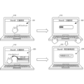
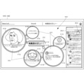
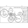
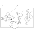
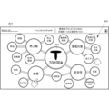
- FIG. 2A is a diagram showing a display screen 201 of the user terminal 210 according to the present embodiment.
- the display screen 201 is also called a canvas, and is a representation of a thinking structure that can be understood at a glance by arranging various elements via links.
- the themes 203 which are the three peripheral elements, include “heliocentrism,” “Renaissance,” and “religious reform.” These subjects 203 are also linked to each other or via peripheral elements 204 (eg, element "typography”).
- One of the themes 203, “Heliocentrism,” is linked to Proposition 212, "Heliocentrism is correct! as a peripheral element.
- Proposition 212 By zooming in on Proposition 212, "The heliocentric theory is correct!, a thought structure diagram with the proposition "The heliocentric theory is correct! as a central element appears.
- one thought structure diagram itself becomes an "element” in this way, and it is possible to create a larger hierarchical thought structure diagram.
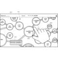
- FIG. 2B is a diagram showing the display screen 211 of the user terminal 210 in the information processing system according to this embodiment.
- the display screen 211 is a thought structure centered on the proposition 212, "Heliocentrism is correct," which is one peripheral element of the display screen 201.
- the display screen 211 of the user terminal 210 of the user who generates the thought structure diagram shows a proposition 212 as a central element that is the center of thought, a plurality of peripheral elements 213 related to the proposition 212, and a combination of the proposition 212 and peripheral elements 213.
- a thought structure diagram is displayed, which is made up of links 214 that connect the elements 214 and links 215 that connect the plurality of peripheral elements 213.
- the links 214 and 215 include links indicated by arrows (triangles ⁇ ), links indicated by rectangles ( ⁇ ), and links indicated by diamonds ( ⁇ ).
- a link indicated by an arrow (triangle ⁇ ) indicates the direction of a causal relationship (parent-child relationship), that is, a relationship that acts from one side but cannot be the other way around.
- a link indicated by a rectangle ( ⁇ ) indicates a relationship in which there is no causal relationship or superiority of information exists, but there is a possibility of mutual interaction.
- Links indicated by diamonds ( ⁇ ) indicate conflicting relationships or contradictory information. Note that the shape of the link on the display screen 211 is just an example, and may be changed depending on differences in expression standards in the thought structure diagram, voting results, etc. described later.
- the proposition 212 as a central element is "Heliocentrism is correct!, and as a peripheral element 213 linked to the proposition 212, for example, "Copernicus” as a peripheral element that supports proposition 212 is causal. It is linked to Proposition 212 by an unrelated rectangle.
- "Eudoxos" a peripheral element that does not support Proposition 212, is linked with a diamond ( ⁇ ) opposing link.
- "Eudoxus” may be linked to proposition 212 by a rectangle with no causal relationship.
- peripheral element 213 that is linked to the peripheral element 213, for example, "Ptolemy's geocentric theory” as a peripheral element that supports the peripheral element "Eudoxus” is linked by a triangle having a causal relationship.
- Proposition 212, "Heliocentric theory is correct!” is a proposition that asks “Yes” or "No,” but for example, "What is the true shape of this universe?" asks "Heliocentric theory” or "Heliocentric theory”. It may be a proposition to ask.
- the size of the figure representing the peripheral element 213 indicates the degree of influence of the central element of the peripheral element 213 on the proposition 212 as considered by the user who generates the thought structure diagram, and the larger the size, the greater the influence. (In the third embodiment described later, the number of votes also influences).
- the influence on the central element can be indicated by the opacity of the peripheral elements rather than the size. Note that, without being limited to size or opacity, a display method is used that allows the user to easily grasp the structure of the thought structure diagram and the influence of peripheral elements on the central element through visual confirmation. For example, elements may be displayed with broken lines, or their colors may be changed.
- the display screen 205 on the user terminals 210 and 220 is a menu that is displayed when the application of this embodiment is started.
- the menu includes structure diagram creation and structure diagram viewing.
- the screen transitions to a structural diagram creation screen 206.
- structural diagram viewing if the user has viewing authority, the screen transitions to a structural diagram viewing screen 216.
- menus for structural diagram registration and structural diagram correction are displayed on the creation screen 206.
- the screen transitions to a structural diagram registration screen 207, and menus for viewing authority settings, editing authority settings, and voting authority settings are displayed. If authority setting is required, at least one of the viewing authority setting, editing authority setting, and voting authority setting is selected and the authority setting is accepted. Note that the voting authority settings are authority settings related to the third embodiment.
- the structural diagram to be viewed is displayed, and a menu for editing the structural diagram is displayed.
- the screen transitions to an editing screen 217 if the user has editing authority. Editing by the user is accepted on the editing screen 217.
- voting screen 218 that accepts votes for each element (theme/proposition, peripheral elements, links).
- votes for peripheral elements can be expressed by users who "support the theme” (theme support), “deny the theme” (theme negation), and "are not appropriate for the theme” (element inappropriate). Accepts selections by
- FIGS. 2D to 2G an operation procedure for the user to generate a thought structure diagram on the display screen of the user terminal 210 will be described.
- FIGS. 2D to 2F show a case where the user terminal 210 is a personal computer, the user terminal 210 may be a portable terminal such as a tablet or a smartphone.
- the operation is shown as an operation on a touch panel, but it is clear that the same operation can be performed by a cursor operation using a mouse and a keyboard.
- FIG. 2D is a diagram illustrating an overview of inputting a subject as a central element in the user terminal 210 of the information processing system according to the present embodiment. There are, for example, the following two procedures for inputting the subject, but the procedure is not limited to these.
- the "ShareB application” is started (or when the browser connects to the ShareB server), a display screen 221 is displayed and the theme setting mode (central element setting mode) is entered.
- the "ShareB application” opens a subject input field in the center of the screen as shown in the display screen 222.
- the theme data is input by key on the display screen 222, the theme "Heliocentrism is correct! is confirmed and displayed as the theme, as shown in the display screen 224, and the screen changes to the element setting mode display screen.
- the input of the subject data is not limited to key input, and may also be input by copying a display sentence in another application.
- the other is the procedure from the display screen 223 to the display screen 224.
- the "ShareB application” is started (or when the browser connects to the ShareB server)
- a display screen 223 is displayed and the theme setting mode is entered.
- the theme setting mode is entered.
- you “drag and drop” a display sentence from another application onto a blank space on the display screen 223, the theme "Heliocentrism is correct!” will be confirmed and displayed as the display screen 224. Transition to the element setting mode display screen.
- FIG. 2E is a diagram illustrating an outline of input of peripheral element data in the user terminal 210 of the information processing system according to the present embodiment.
- peripheral element setting mode peripheral element setting mode
- the "ShareB application” opens input fields for peripheral elements around the subject as shown on the display screen 232.
- "Copernicus” is determined and displayed as the peripheral element, as shown in the display screen 234, and the display screen changes to a link setting mode display screen.
- the input of peripheral elements is not limited to key input, and may be input by copying or linking a display image (including a video) or a display sentence in another application.
- the other is the procedure from the display screen 233 to the display screen 234.
- the display screen 231 in the element setting mode for example, if you "drag and drop” a display image (including a video) or a display sentence in another application into a blank area of the display screen 233 in order to input a copy or link it, As shown in the display screen 234, "Copernicus” is determined and displayed as a peripheral element, and the display screen changes to a link setting mode display screen. Furthermore, by copying and inputting a web URL and "drag-and-dropping" it, the information of the link destination can be stored in the element.
- the degree of influence of "Copernicus” as a peripheral element on the theme as a central element is input from an influence input unit 236.
- the degree of this influence is expressed by the size, color, etc. of "Copernicus” as a peripheral element, and is stored in the database.
- FIG. 2F is a diagram showing an overview of link data input in the user terminal 210 of the information processing system according to this embodiment.
- the links include, for example, the following three links, but are not limited to these. Furthermore, the link input operations are not limited to these.
- a menu 245 is displayed that shows three types of links to connect.
- the subject "Heliocentrism is correct!” and the element "Copernicus” are connected by a link that has no causal relationship.
- a strength input section 246 for inputting the strength of the link is displayed on the display screen 242.
- the strength of the input link is represented by the thickness and color of the link and is stored in the database.
- FIG. 2G is a diagram illustrating an overview of a thought structure diagram registration request in the user terminal 210 of the information processing system according to the present embodiment.
- the upper diagram in FIG. 2G shows the disclosure range setting screen 251.
- a user who generates a thought structure diagram and requests registration selects one from three types of disclosure range selection menu 255.
- the three types of disclosure range are complete disclosure, limited disclosure, and private disclosure. If full disclosure is selected, it will be viewable to all users. If limited disclosure is selected, only the members designated by the creator of the thought structure diagram as designators can view it. Note that the members may be specified on an individual basis or on an attribute basis such as age. If private is selected, only the creator of the thought structure diagram can view it. Note that the disclosure range is not limited to these three types. For example, you may specify members who do not want to be made public with limited public access.
- FIG. 2G shows the editing authority setting screen 252.
- a user who generates a thought structure diagram and requests registration selects one from three types of editing authority selection menu 256.
- the three types of editing authority are full grant, limited grant, and no grant. If full grant is selected, full editing privileges are granted and peripheral elements (nodes), links, and central elements such as propositions and themes can be instantly added or deleted.
- the editing authority is not limited to the three types of editing authority illustrated here, and other editing authority may be provided.
- a user is basically given limited editing privileges between full editing privileges and limited editing privileges, but full editing privileges are granted only to users who have gained a lot of support in the past for limited editing. Possible settings include .
- a hidden parameter is set for each user, and the user's reliability as an editor is scored and stored, and the thought structure diagram generation user is given full editing authority or limited editing authority depending on the score. to be set. For example, settings such as "give full editing authority to people with a score of 500 or higher" are made.
- the creator of the thought structure diagram can set the granting of editing authority for each thought structure diagram. For example, it is possible to grant complete editing authority only to the creator (self) and not grant any editing authority to other users. On the other hand, it is also possible to set up a fair thinking structure diagram generation environment in which all users, including the creator, have limited editing authority. These editing authority grant settings are visible to all users. Furthermore, a function may be provided to set the thinking structure diagram so that it cannot be changed into an impossible structure by editing.
- the creator After setting the disclosure range and editing authority of the generated thought structure diagram, the creator registers the generated thought structure diagram in the information processing device (ShareB server) from the user terminal 210.
- the information processing device ShareB server
- FIG. 2H is a diagram showing an overview of editing instructions from the user terminal 220 of the information processing system according to this embodiment.
- the user terminal 220 is shown as a terminal that makes a thought structure diagram editing request and is different from the user terminal 210 of the thought structure diagram creator, it may be the same terminal.
- a process is being performed to restrict privileges. This is to prevent the original thought structure diagram from being changed into an impossible structure or deviating from the intention of the user who created it, if editing of the thought structure diagram is freely permitted.
- each user is given the option of editing ranked into three types as described above.
- a configuration is adopted in which privileges are granted in advance.
- a case will be described in which an attempt is made to add and edit a new element by double-clicking on the thought structure diagram on the display screen 261 of the element setting mode on the other user terminal 220.
- the editing authority is checked based on the user ID of the user using the user terminal 220, and if there is complete editing authority, an element column opens as shown in the display screen 262, and the screen changes to a display screen 263 in link setting mode. After that, a new element is added on the screen of the user terminal 220 and the thinking structure diagram is edited in the same manner as the operating procedure shown in FIGS. 2D and 2E.
- the user who generated the thought structure diagram can also check the settings (information) in the opened element column and restrict editing.
- the element or link that you attempt to add will be displayed as semi-transparent (indicated by a broken line in FIG. 2H), as shown in the display screen 265. Therefore, the addition of elements to the thought structure diagram is made to wait until the results of the user's approval vote are released. If the voting result is approved, the requested element is added as shown on the display screen 263. On the other hand, if the voting result is negative, the requested element disappears as shown on the display screen 266.
- FIG. 3A is a block diagram showing the configuration of an information processing system 300 according to this embodiment.
- the information processing system 300 includes a ShareB server 310 as an information processing device connected via a network 320, a user terminal 210 of a user who generates and posts thought structure diagrams, and publishes the thought structure diagrams, and the published thought structure diagrams. and a user terminal 220 of a user who shares and edits the same.
- the ShareB server 310 has a database 311, stores registered users and posted thought structure diagrams, and makes them publicly available for sharing.
- the user terminal 210 while communicating with the ShareB server 310, generates a thought structure diagram according to the operating procedures shown in FIGS. 2C to 2F and posts it to the ShareB server 310.
- the user terminal 220 views the thought structure diagram stored in the ShareB server 310 according to the operating procedure shown in FIG. 2G, and requests editing of the thought structure diagram if necessary.
- the user terminals 210 and 220 are depicted separately in FIG. 3A for convenience of explanation, the same user terminal may provide both functions.
- FIG. 3B is a sequence diagram showing the operation procedure of the information processing system 300 according to this embodiment.
- step S301 the ShareB server 310, the user terminal 210 (of the thought structure diagram generation user), and the user terminal 220 (of the thought structure diagram viewing user) become able to communicate by starting the ShareB application or by connecting with a browser. . Then, the ShareB server 310 and the user terminal 210 transition to the theme setting mode and wait for the setting of the theme as the central element.
- step S303 when a theme is input from the user terminal 210, in step S305, the ShareB server 310 acquires the theme and displays the theme in the center of the screen of the user terminal 210, and the ShareB server 310 and the user terminal 210 Transition to element setting mode and wait for peripheral element settings.
- step S307 when a peripheral element is input from the user terminal 210, in step S309, the ShareB server 310 acquires the element and displays the element around the subject on the screen of the user terminal 210, and the ShareB server 310 and the user terminal At step 210, the process transitions to link setting mode and waits for link setting.
- the ShareB server 310 acquires the link and creates a link between the subject and the elements or between the elements selected on the screen of the user terminal 210 in step S313. display.
- FIG. 3B shows a procedure for connecting elements with links each time they are added, the procedure is not limited to this, and may be a procedure of adding a plurality of elements and then connecting them together with links.
- a procedure may be provided to check the completion of the thought structure diagram. For example, if there is an element in the thought structure diagram that has no links connected to it, an error message will be displayed, and the user will still be able to link that element. If the element is not connected, the element may disappear when the thought structure diagram completion process is completed.
- the user of the user terminal 210 sets the disclosure range and editing authority and instructs posting (registration) of the thought structure diagram in step S315.
- the ShareB server 310 stores the thinking structure diagram posted from the user terminal 210 by setting the disclosure range and editing authority, and stores the thought structure diagram according to the disclosure range set on the user terminals 210 and 220. Publish. The published thinking structure diagram is viewed and shared at the user terminals 210 and 220. Note that when storing or viewing a thought structure diagram, the ShareB server 310 changes the arrangement of elements and links for thought structure diagrams that are difficult to see, such as links passing over elements or links crossing each other. automatically adjusts and rearranges it for easier viewing.
- processing for automatically adjusting the arrangement of elements and links and rearranging them for easier viewing may be performed while the thought structure diagram is being generated.
- the server may automatically prepare the size of peripheral elements, types of links, and peripheral elements themselves according to the theme. .
- step S321 when the user terminal 210 or 220 requests to edit (add or change) the thought structure diagram being viewed, the ShareB server 310 determines whether the user who requested the editing has full editing authority in step S323. , or check whether the editing authority rank is sufficient. If the user who requested editing has full editing authority or the rank of editing authority is sufficient, the ShareB server 310 allows editing (additions and changes) to the thought structure diagram in step S325, and displays the editing results. Instruct the display of a thought structure diagram. The user terminals 210 and 220 share the edited thought structure diagram in step S327.
- the ShareB server 310 notifies the user of no editing authority in step S331.
- the user terminal 220 notifies (warns) the user that he does not have editing authority.
- the ShareB server 310 requests the user terminal 220 (and the user terminal 210) to vote for approval of the edit in step S341.
- the user terminal 220 requests the user to vote for approval of the edit. If there is an approval vote, the user terminal 220 notifies the ShareB server 310 of the approval vote in step S345. Further, upon receiving a request for an approval vote, the user terminal 210 requests the user to vote for approval of the edit in step S347. If there is an approval vote, the user terminal 210 notifies the ShareB server 310 of the approval vote in step S349.
- the ShareB server 310 totals the approval votes from the user terminals 220 (and the user terminals 210) in step S351, and determines whether the edit is approved or rejected in step S353. Then, in step S355, the ShareB server 310 performs a process according to the determination result; if the edit is approved, the process is in step S325; if the edit is denied, the process is in step S331.
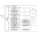
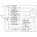
- FIG. 4 is a block diagram showing the functional configuration of the ShareB server 310 as an information processing device according to this embodiment.
- the ShareB server 310 includes a communication control section 401 , a subject acquisition section 402 , a theme display instruction section 412 , a peripheral element acquisition section 403 , a peripheral element display instruction section 413 , a link acquisition section 404 , and a link display instruction section 414 and a database 311.
- the ShareB server 310 also includes a thought structure diagram generation unit 405, a viewing request reception unit 406, a thought structure diagram publication unit 407, a thought structure diagram editing instruction reception unit 408, an editing authority confirmation unit 409, and an editing authority notification unit 405. 410, and a thought structure diagram registration portion 411.
- inputs to the subject display instruction section 412, peripheral element display instruction section 413, and link display instruction section 414 are simplified to avoid complexity.
- the ShareB server 310 also includes an approval vote aggregation unit 415 and an approval vote determination unit 416.
- the communication control unit 401 controls communication with the user terminals 210 and 220 via the network 320.
- the theme acquisition unit 402 acquires the theme transmitted from the user terminal 210 as a central element.
- the theme display instruction unit 412 instructs to display the acquired theme at a predetermined position (for example, the center of the screen) of the user terminal 210.
- the peripheral element acquisition unit 403 acquires peripheral elements transmitted from the user terminal 210.
- the peripheral element display instruction unit 413 instructs to display the acquired peripheral elements at a predetermined position (for example, around the subject) of the user terminal 210.
- the link acquisition unit 404 acquires the link transmitted from the user terminal 210 together with its type.
- the link display instruction unit 414 instructs to display the acquired link at a predetermined position on the user terminal 210 (for example, between a subject and a peripheral element, or between a peripheral element and a peripheral element) according to the type of the link.
- the database 311 stores data, parameters and programs necessary for processing by the ShareB server 310, and a thought structure diagram including a theme, peripheral elements, and links.
- the thought structure diagram generation unit 405 has a thought structure diagram generation table 451, and generates a thought structure diagram using the acquired or stored themes, peripheral elements, and links.
- the viewing request receiving unit 406 receives a request for viewing the thought structure diagram from the user terminal 220.
- the thought structure diagram publishing unit 407 publishes the thought structure diagram to the user terminals 210 and 220 in response to the thought structure diagram viewing request, taking into consideration the set disclosure range.
- the thought structure diagram publishing unit 407 has a publication restriction unit that restricts publication of the thought structure diagram by the thought structure diagram publication unit 407 based on information on the disclosure range.
- the thought structure diagram editing instruction receiving unit 408 receives thought structure diagram editing instructions from the user terminals 210 and 220.
- the editing authority confirmation unit 409 confirms the editing authority of the user who has instructed to edit the thought structure diagram.
- the editing authority confirmation unit 409 allows the user to edit the thought structure diagram if the user has been granted complete editing authority.
- the editing authority confirmation unit 409 sends the editing authority notification unit 410 to the editing authority notification unit 410. The user is notified from the user terminal 220 that there is no editing authority.
- the editing authority confirmation unit 409 causes the editing authority notification unit 410 to notify the user of an approval vote from the user terminal 220.
- Approval vote tallying unit 415 tallies approval votes from user terminals 220 (and user terminals 210) within a predetermined period of time.
- the approval vote determination unit 416 determines whether the edit requested from the user terminal 220 is approved or rejected based on the total of approval votes. If the approval vote determination unit 416 approves the editing, it instructs the thought structure diagram generation unit 405 to confirm the editing, and if it disapproves the editing, it instructs the editing to disappear.
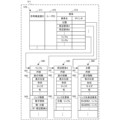
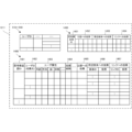
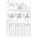
- the database 5A and 5B are diagrams showing the configuration of the database 311 according to this embodiment.
- the database 311 stores data, parameters and programs necessary for processing by the ShareB server 310, and a thought structure diagram including themes, elements, and links.
- the database 311 includes a subject storage section 510, a peripheral element storage section 520, a link storage section 530, and a disclosure range/editing authority registration section 540.
- FIG. 5A shows data acquired from the user terminals 210 and 220, and basic stored data such as user registration is not shown in FIG. 5A.
- the theme storage unit 510 stores a theme 513 as a central element set on the user terminal 210 in association with the user ID 511 for generating the thought structure diagram and the terminal ID 512 of the user terminal 210.
- the theme 513 may include the position on the display screen where the theme is displayed.
- the peripheral element storage unit 520 stores the peripheral elements 523 set in the user terminal 210 and the theme 524 related to the peripheral elements 523 in association with the user ID 521 for generating the thought structure diagram and the terminal ID 522 of the user terminal 210. Store. Note that the peripheral element 523 may include a position on the display screen where the peripheral element is displayed.
- the link storage unit 530 stores a link 533 set on the user terminal 210, a subject 534 connected by the link 533, peripheral elements 535, and A peripheral element 536 and a link type 537 of the link 533 are stored.
- the link storage unit 530 also stores a subject 538 related to the link 533. Note that from the theme 534, peripheral elements 535, and peripheral elements 536, two connected by a link 533 are selected. Further, the link 533 may include the position on the display screen where the link is displayed, or the position of the link may be adjusted from two positions connected by the link 533.
- the disclosure range/editing authority registration unit 540 stores the presence or absence of editing authority 542, the rank of editing authority 543, and the disclosure range 544 in association with the user ID 541.
- the database 311 may store a threshold value to be compared with the editing authority rank 543 or an editing threshold value for each thought structure diagram.
- FIG. 5B is a diagram showing the configuration of the thought structure diagram storage unit 570 stored in the database 311. Although FIG. 5B shows the configuration of one thought structure diagram, many registered thought structure diagrams are stored.
- the thought structure diagram storage unit 570 stores, in association with the thought structure diagram ID 571, the user ID 572 that registered this thought structure diagram and the elements 573 that constitute the thought structure diagram.
- the element 573 the subject of the element name, peripheral elements, links, and pointers to the theme data storage section 580, peripheral element data storage section 590, and link data storage section 500 representing the respective elements are stored.
- FIG. 5B if it is desired to maintain the history of editing processing, it is possible to record the edited user ID separately from the user ID registered in the user ID 572 corresponding to the element 573 of the editing result.
- the theme data storage unit 580 stores the theme content 581, display information 582, link destination peripheral elements 583, and the like.
- the display information 582 includes the display position, shape, size, color, etc. of the subject.
- the linked peripheral element 583 stores, for example, that it is connected to peripheral element A by link a, and that it is connected to peripheral element B by link b.
- the peripheral element data storage unit 590 (peripheral element A) stores the content 591, display information 592, link destination element 593, etc. of the peripheral element A.
- the display information 592 includes the display position, shape, size, color, etc. of the peripheral element A.
- the link destination element 593 stores, for example, that it is connected to the subject by a link a. Note that if there is a link with the peripheral element B, the peripheral element B and the link name are stored.
- the link data storage unit 500 (link a) stores the contents 501, display information 502, link information 503, etc. of link a.
- the display information 502 includes the display position, shape, size, color, etc. of link a.
- the link information 503 stores, for example, that this link represents a parent-child relationship, and that the direction is that the parent is the subject and the child is the peripheral element A. Note that if the link relationship is equal or conflicting, this is stored in the link information 503.
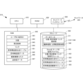
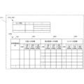
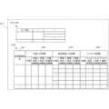
- FIG. 5C is a diagram showing the configuration of the thinking structure diagram generation table 451 according to this embodiment.
- the thought structure diagram generation table 451 is used when the thought structure diagram generation unit 405 generates a thought structure diagram using the acquired or stored theme as a central element, peripheral elements, and links.
- the thought structure diagram generation table 451 includes an attribute table 550 that shows the attributes of the generated thought structure diagram, and a configuration table 560 that shows the structure of the thought structure diagram.
- the attribute table 550 shows the thought structure diagram ID 553, the creation date 554, the set disclosure range 555, and the set editing authority in association with the user ID 551 that generated the thought structure diagram and the terminal ID 552 of the user terminal. 556 is stored.
- the configuration table 560 stores themes 562 and peripheral elements 563 associated with each theme 562 in association with the thought structure diagram ID 561.
- Theme 562 includes the content and display position of the theme.
- the peripheral element 563 includes the content of the peripheral element, the display position, the link with the subject and the type of link, and the link with other peripheral elements and the type of link.
- peripheral element 563 that is not linked to the theme 562, the "link to theme” and “link type” data are not significant. Furthermore, when one peripheral element 563 links to multiple themes 562, the same peripheral element has multiple “links with themes” and “link types.”
- FIG. 6 is a block diagram showing the hardware configuration of the ShareB server 310 according to this embodiment.
- a CPU (Central Processing Unit) 610 is a processor for arithmetic control, and implements the components shown in FIG. 4 by executing a program.
- a ROM (Read Only Memory) 620 stores fixed data and programs such as initial data and programs.
- Network interface 630 controls communication with user terminals 210 and 220 via network 320.
- a RAM (Random Access Memory) 640 is a random access memory that the CPU 610 uses as a temporary storage work area.
- the RAM 640 has an area reserved for storing data necessary to implement this embodiment.
- the user ID (terminal ID) 641 is the ID of the user or user terminal communicating with the ShareB server 310.
- the theme 642 is the data of the theme as a central element received from the user terminal.
- the peripheral element 643 is peripheral element data received from the user terminal.
- Link 644 is link data received from the user terminal.
- the thought structure diagram generation table 451 is a table used by the thought structure diagram generation unit 405 described in FIG. 6B to generate a thought structure diagram.
- the thought structure diagram data 645 is thought structure diagram data that is generated and shared with users.
- the editing authority comment 646 is a comment for notifying the user when the user does not have editing authority for the thought structure diagram or when the level of editing authority is low.
- the editing authority comments 646 also include comments requesting an editing approval vote.
- Transmission/reception data 647 is data transmitted/received to/from user terminals 210 and 220 via network 320.
- the storage 650 stores a database, various parameters, and the following data or programs necessary to implement this embodiment.
- the database 311 is a database that stores synthetic data, and includes storage units 510 to 530 for subjects/peripheral elements/links, and a disclosure range/editing authority registration unit 540, as shown in FIG. 5A.
- the ShareB server processing program 651 is a program that controls the entire ShareB server 310.
- the theme/peripheral element/link acquisition module 652 is a module that acquires the theme, peripheral elements, and link settings from the user terminal.
- the thought structure diagram generation module 653 is a module that generates a thought structure diagram using the acquired theme, peripheral elements, and links.
- the thought structure diagram sharing module 654 is a module that publishes the thought structure diagram in response to a viewing request from a user terminal and allows users to share the thought structure diagram, and also includes a process of determining the disclosure range.
- the thought structure diagram editing module 655 is a module for editing the thought structure diagram by the user, and also includes processing for determining editing authority.
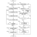
- FIG. 7 is a flowchart showing the processing procedure of the ShareB server 310 according to this embodiment. Note that this flowchart is executed by the CPU 610 in FIG. 6 using the RAM 640 to realize the components in FIG. 4.
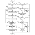
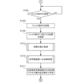
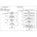
- step S711 the ShareB server 310 determines whether or not a thought structure diagram is to be generated. If the thought structure diagram is to be generated, a thought structure diagram generation process is executed in step S713.
- the ShareB server 310 determines in step S721 whether or not the thought structure diagram is to be viewed. If the viewing is a thought structure diagram, the ShareB server 310 determines in step S722 whether the viewing user has viewing authority. If there is no viewing authority, the ShareB server 310 notifies the viewing user that there is no viewing authority in step S724. If the ShareB server 310 has the viewing authority, in step S723, the ShareB server 310 acquires the corresponding thought structure diagram for which viewing is requested. Then, in step S725, the ShareB server 310 publishes the thought structure diagram as a thought structure diagram sharing process (sharing with terminals that have access rights).
- the ShareB server 310 determines in step S731 whether the purpose is to edit a thought structure diagram. If the edit is a thought structure diagram, the ShareB server 310 obtains the user ID of the user who requested the edit in step S733. Then, in step S735, the ShareB server 310 checks the editing authority for the thought structure diagram to be edited from the acquired user ID. In step S737, if the ShareB server 310 is granted full authority based on the editing authority check result, in step S739, the ShareB server 310 executes the thought structure diagram editing process and shares the editing result.
- the ShareB server 310 notifies the user from the user terminal that there is no editing authority in step S741. Furthermore, if limited editing authority is granted, the ShareB server 310 performs editing processing in step S743 based on the voting result for approval of editing. That is, if the voting result is approval for editing, the edited portion is determined. On the other hand, if the voting result is to reject the edit, the edited portion is deleted.
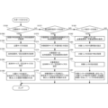
- FIG. 8 is a flowchart showing the procedure of thought structure diagram generation processing S713 according to this embodiment.
- step S801 the ShareB server 310 waits to receive a subject as a central element from the user terminal 210.
- the ShareB server 310 stores the received theme in the database 311 in step S803, and instructs it to be displayed at a predetermined position (eg, the center of the screen) on the display screen of the user terminal 210.
- step S805 the ShareB server 310 waits to receive peripheral elements from the user terminal 210.
- the ShareB server 310 stores the received peripheral element in the database 311 in step S807, and instructs it to be displayed at a predetermined position (for example, around the subject) on the display screen of the user terminal 210. do.
- step S809 the ShareB server 310 waits to receive a link from the user terminal 210.
- the ShareB server 310 stores the received link in the database 311 in step S811, and displays it at a predetermined position on the display screen of the user terminal 210 (for example, between the subject and peripheral elements, or between the peripheral elements). (between surrounding elements).
- FIG. 8 shows a procedure for connecting elements with links each time they are added, the procedure is not limited to this, and may be a procedure of adding a plurality of elements and then connecting them together with links.
- step S813 the ShareB server 310 determines whether the generation of the thought structure diagram is finished. If the generation of the thought structure diagram is not completed, the ShareB server 310 returns to step S801 and repeats the setting of peripheral elements and links in steps S805 to S811.
- the ShareB server 310 checks whether the thought structure diagram is complete or incomplete in step S815. For example, check to see if there are any unreasonable parts in the structure of the thought structure diagram (for example, whether there are any elements that are dangling with no links). Then, in step S817, the ShareB server 310 determines whether the thought structure diagram is incomplete. If it is incomplete, the process returns to step S801 and repeats the settings of the subject, peripheral elements, and links in steps S801 to S811.
- the ShareB server 310 receives the editing authority and disclosure range from the user terminal 210 and sets it in the generated thought structure diagram in step S819. Then, in step S821, the ShareB server 310 registers the thought structure diagram in which the editing authority and disclosure range have been set. Note that the ShareB server 310 may perform a process of rearranging elements, links, etc. in step S821 in order to make the thought structure diagram easier to see before registration.
- the editing authority and disclosure range are set when the thought structure diagram is complete, but they can be set or changed during the generation of the thought structure diagram, or after the thought structure diagram is generated. You can do it like this.
- FIG. 9 is a block diagram showing the functional configuration of the user terminals 210 and 220 according to this embodiment.
- the user terminal 210 includes a communication control unit 901 and an input/output interface 902.
- the communication control unit 901 controls communication with the ShareB server 310 via the network 320.
- a display section 921 and an operation section 922 are connected to the input/output interface 902.
- the display unit 921 displays a display screen when generating, viewing, or editing a thought structure diagram. Additionally, the status of the user terminal 210 is notified.
- the operation unit 922 also accepts user input and operations when generating, viewing, and editing a thought structure diagram. Note that in this embodiment, when a smartphone, a tablet, or the like is used as the user terminal 210, the display section 921 and the operation section 922 are integrated as a touch panel.
- the user terminal 210 also includes a theme acquisition section 903, a theme transmission section 904, a peripheral element acquisition section 905, a peripheral element transmission section 906, a link acquisition section 907, a link transmission section 908, and a thought structure diagram reception section. 909, and a thought structure diagram display instruction section 910. Note that in FIG. 9, functional units that instruct display of the subject, peripheral elements, and links on the display unit 921 are omitted in order to avoid complication of illustration.
- the user terminal 210 also includes an editing authority/disclosure range acquisition section 917 and a thought structure diagram registration requesting section 918.
- the theme acquisition unit 903 acquires the theme input from the operation unit 922 as the central element. Then, the theme transmitting unit 904 transmits the acquired theme to the ShareB server 310.
- the peripheral element acquisition unit 905 acquires peripheral elements input from the operation unit 922. Then, the peripheral element transmitting unit 906 transmits the acquired peripheral element to the ShareB server 310.
- the link acquisition unit 907 acquires the link input from the operation unit 922. The link transmitter 908 then transmits the acquired link to the ShareB server 310.
- the thought structure diagram receiving unit 909 receives the thought structure diagram that is being generated or has been generated from the ShareB server 310.
- the thought structure diagram display instruction section 910 instructs the display section 921 to display the received thought structure diagram.
- the thought structure diagram receiving section 909, the thought structure diagram display instruction section 910, and the display section 921 function as a central element display section, a peripheral element display section, and a link display section.
- the editing authority/disclosure range acquisition unit 917 acquires the editing authority and disclosure range of the generated thought structure diagram from the operation unit 922.
- the thought structure diagram registration requesting unit 918 sends the thought structure diagram in association with the acquired editing authority and disclosure range, and requests the ShareB server 310 to post (register) the thought structure diagram.
- the user terminal 210 includes a thought structure diagram viewing request acquisition unit 911 , a thought structure diagram viewing request unit 912 , a thought structure diagram editing instruction acquisition unit 913 , a thought structure diagram editing transmission unit 914 , and an editing authority receiving unit 915 and an editing authority notification section 916.
- the thought structure diagram viewing request acquisition unit 911 acquires a thought structure diagram viewing request through an operation from the operation unit 922 .
- the thought structure diagram viewing request unit 912 then transmits a viewing request to the ShareB server 310.
- the thought structure diagram corresponding to the viewing request is displayed on the display section 921 by the thought structure diagram receiving section 909 and the thought structure diagram display instruction section 910.
- the thought structure diagram editing instruction acquisition unit 913 acquires a thought structure diagram editing request through an operation from the operation unit 922 . Then, the thought structure diagram editing and sending unit 914 sends the editing request to the ShareB server 310.
- the editing authority receiving unit 915 receives a message indicating that there is no editing authority when the user's editing authority is not satisfied in response to a thought structure diagram editing request. Then, the editing authority notification unit 916 notifies the user from the display unit 921 that there is no editing authority.
- FIG. 10 is a flowchart showing the processing procedure of the user terminals 210 and 220 according to this embodiment. This flowchart is executed by the CPUs of the user terminals 210 and 220 using the RAM to realize the components of FIG.
- the user terminal 210 will be described below as a representative example.
- step S1011 the user terminal 210 determines whether or not a thought structure diagram is to be generated. If the thought structure diagram is to be generated, the user terminal 210 displays a thought structure diagram generation screen in step S1013 (see FIG. 2C). In step S1015, the user terminal 210 transmits the input subject to the ShareB server 310 and displays it on the display screen. In step S1017, the user terminal 210 transmits the input peripheral elements to the ShareB server 310 and displays them on the display screen. In step S1019, the user terminal 210 transmits the input link to the ShareB server 310 and displays it on the display screen. Note that although a procedure has been shown in which each additional peripheral element is connected with a link, the procedure is not limited to this, and the procedure may be such that after adding a plurality of peripheral elements, they are connected together with a link.
- step S1021 the user terminal 210 determines whether the generation of the thought structure diagram is complete based on the user's instruction. If the generation of the thought structure diagram is not completed, the user terminal 210 returns to step S1015 and repeats the input of the subject, element, and link in steps S1015, S1017, and S1019 until the generation of the thought structure diagram is completed.
- the user terminal 210 receives settings for editing authority and disclosure range in step S1023. Then, in step S1025, the user terminal 210 posts and saves the thought structure diagram with editing authority and disclosure range settings to the ShareB server 310 for sharing the thought structure diagram.
- the user terminal 210 determines in step S1031 whether or not the thought structure diagram is to be viewed. If the thought structure diagram is to be viewed, the user terminal 210 waits for a result from the ShareB server 310 as to whether or not the viewing authority is satisfied in step S1033. If viewing authority is granted, the user terminal 210 receives and displays the thought structure diagram to be viewed in step S1035. If the viewing authority is not granted, the user terminal 210 notifies the user that the viewing authority is not granted in step S1037. In step S1039, the user terminal 210 determines whether there is an instruction to edit the thought structure diagram. If there is no instruction to edit the thought structure diagram, the process ends.
- the user terminal 210 waits for a result from the ShareB server 310 as to whether the editing authority is satisfied in step S1041. If complete editing authority or limited editing authority has been granted, the user terminal 210 inputs editing of the thought structure diagram in step S1043. If there is no editing authority, the user terminal 210 notifies the user that there is no editing authority in step S1045.
- the user terminal 210 inputs the editing of the thought structure diagram in step S1039, and is notified from the ShareB server 310 that the inputted editing has become an approval vote, and selects whether to approve or disapprove. wait for something You can also vote for approval yourself. Since these processes wait for the result of the approval vote, they may be performed in parallel with the thought structure diagram generation process and the thought structure diagram viewing process, but are omitted in FIG. 10.
- the thought structure diagram can be easily generated on the user terminal 210 of the user who publishes the thought structure diagram, and can be shared with the user terminals 220 of other users.
- the information processing system according to this embodiment is different from the second embodiment in that the thought structure diagram is changed in response to the user's vote on the displayed themes and elements.
- the other configurations and operations are the same as those in the second embodiment, so the same configurations and operations are given the same reference numerals and detailed explanation thereof will be omitted.
- the following voting operation by the user is performed on a thought structure diagram generated and registered by the generating user, or on a thought structure diagram edited by the user after registration. May be done.
- a voting model of the thought structure diagram in which the element size, link strength, etc. are not set may be provided, and voting may be performed on the thought structure diagram voting model.
- the voting model of the thought structure diagram may be registered or edited by the user.
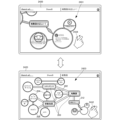
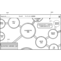
- FIG. 11A is a diagram showing voting operations of user terminals 1110 and 1120 in the information processing system according to this embodiment.
- the upper diagram in FIG. 11A shows a display screen 1111 of a thought structure diagram generated by the user on the user terminal 1110.
- a thought structure including a subject 212 as a central element, peripheral elements 213, and links 214 is displayed.
- a ring 1112 for displaying voting results by users is displayed around the peripheral element 213.
- the size of the peripheral elements 213 is not large or small (the importance is the same), and the voting results for both the theme 212 and the ring 1112 correspond to the theme support rate/theme rejection rate. No coloring has been done.
- the center diagram of FIG. 11A shows a state in which the user has selected "Eudoxos", which is the peripheral element 213, as a voting destination.
- a window 1101 for explaining Eudoxos opens, and along with the explanation of Eudoxos, it shows "supports the theme” (hereinafter referred to as “theme support”), “denies the theme” (hereinafter referred to as “theme negation”), and "appropriate for the theme”.
- a soft button will be displayed to vote for either “Not reliable” (or “Unreliable”: hereinafter referred to as "Inappropriate element”). Note that even when another peripheral element is selected as a voting destination, the same soft button is displayed along with an explanation of the peripheral element.
- the lower diagram in FIG. 11A shows a state in which the user has voted for "deny the subject.”
- the voting results are sent to the ShareB server 1210 and stored in the database 1211. Then, the display (size, shape, color, etc.) of the surrounding elements will be changed according to the accumulated voting results, and this will be reflected on other surrounding elements and themes associated with the surrounding elements via links, and will also be reflected in the links. .
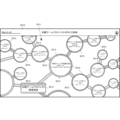
- FIG. 11B is a diagram showing changes in the display screens 1111 of the user terminals 1110 and 1120 in the information processing system according to this embodiment, reflecting voting.
- FIG. 11B corresponds to FIG. 11A and shows a state in which voting by users has not yet been performed.
- the upper diagram in FIG. 11B is a display screen 1141 of a thought structure diagram when a vote is performed by the users and as a result of the voting, there are many votes in favor of the theme for peripheral elements of Copernicus.
- the inappropriate votes are subtracted from the total number of votes as the voting results of the theme 212 as the central element and the peripheral elements 213, such as supporting the theme, denying the theme, or inappropriate, from the users who viewed the thought structure diagram.
- the votes cast and the voting percentage (rate) are displayed.
- the size of each peripheral element 213 represents the total number of votes minus inappropriate votes.
- the peripheral element 213 of Copernicus which is large in size, has a large number of votes obtained by subtracting inappropriate votes from the total number of votes, indicating that it has a large influence on the theme 212.
- the peripheral element 213 of Regiomontanus which is small in size, has few votes, including support for the theme/denial of the theme, or many votes that the element is inappropriate, indicating that it has little influence on the theme 212.
- Other peripheral elements 213 also do not have many votes and are small in size.
- the percentage of votes for theme support (grid) 1113 and theme negation (halftone dots) 1114 is displayed in different colors, for example. (Different colors are indicated by different patterns).
- the percentage of votes for theme support 1113 and theme negation 1114 is displayed in a ring 1112 around an element figure (for example, a circle) in association with different colors of the theme.
- votes for each peripheral element 213 are reflected in the subject 212 and other peripheral elements 213 associated with the link 214. Whether or not to reflect votes between elements may be selected when setting the link 214 or the like.
- voting for the link 214 is easily visible and affects the thought structure diagram visually, it is desirable that its shape be determined according to surrounding elements. For example, when creating or editing a thought structure diagram, the user sets it to "Equal (rectangle ⁇ )," but as a result of subsequent voting, one of the two peripheral elements connected by a link supports the heliocentric theory. It is conceivable that if one vote results in one vote and the other vote results in "supporting geocentric theory", the shape of the link between them is automatically changed to a "confrontation (diamond ⁇ )" link. Note that the shape of the link 214 may be determined according to surrounding elements when setting the link 214, or the shape may be selected by the user who has set the link 214. Further, the influence of voting on the link 214 is not limited to the method of expressing it as an influence on opacity, but various display methods that can be considered include visual recognition such as the shape of the link or a broken line.
- the theme 212 has a high proportion of theme support 1113. Furthermore, the reason why there is a high percentage of theme support 1113 in theme 212 is due to Copernicus's positive interest in peripheral elements 213, and the voting results for other peripheral elements 213 do not have much influence on thoughts about theme 212. This can be understood by looking at the display screen 1141 at a glance. For example, the display screen 1141 well represents the thought structure after Newton on the theme of "Heliocentrism is correct!, and the current situation is that the number of supporters of the heliocentric theory is decreasing more and more. Be able to understand thoughts structurally.
- the lower part of FIG. 11B is a thought structure diagram display screen 1151 when users vote and as a result of the voting, there are many negative votes for the theme in peripheral elements of Eudoxus.
- the display screen 1151 displays inappropriate votes from the total number of votes as voting results such as support for the theme/denial of the theme/inappropriate elements for the theme 212 as the central element and the peripheral elements 213 from users who viewed the thought structure diagram.
- the subtracted votes and the percentage of votes supporting the theme/voting against the theme are displayed.
- the total number of votes minus inappropriate votes is represented by the size of each peripheral element 213.
- the peripheral element 213 of Eudoxos which is large in size, has many votes, including those supporting the theme/denying the theme, while there are few votes indicating that the element is inappropriate, indicating that it has a large influence on the theme 212.
- the peripheral element 213 of Copernicus which is small in size, there are few votes including support for the theme/denial of the theme, or there are many votes indicating that the element is inappropriate, which shows that the influence on the theme 212 is small. Note that even if the votes including support for the theme/denial of the theme are the same, the elements with many votes for element inappropriateness and elements with few votes are displayed in a distinguishable manner.
- the size of the peripheral element 213 of Eudoxus is large and the size of the peripheral element 213 of Copernicus is small, and as a result, it is shown that the theme 212 has fewer theme supports 1113 than theme negations 1114.
- this thought structure diagram may well represent the thought structure shared by many people. This means that it can be evaluated as being effective in generating thought structure diagrams in the future.
- voting on the theme 212 (or proposition) as a central element is a vote for or against, and voting for peripheral elements or links is not a vote for or against, but rather a vote for determining the attributes and importance of information. becomes. For example, if the user looks at the peripheral elements 213 of Copernicus and feels that "this peripheral element supports the heliocentric theory," he or she votes for "this peripheral element supports the heliocentric theory.” On the other hand, if you feel that ⁇ this peripheral element supports the geocentric theory,'' you will vote for ⁇ this peripheral element supports the geocentric theory.'' Depending on the ratio, the color, shape, etc.
- this peripheral element is reduced in size, and when it is reduced to the minimum size, its opacity is further reduced. The opacity then reaches its lowest level, and the element disappears after a certain period of time.
- the display method of ⁇ reducing the size'' or ⁇ lowering the opacity'' may be used. However, other display methods may be used.
- voting for a proposition (or theme) as a central element is each user's support for/denial of the theme, and the size of peripheral elements corresponding to the number of votes represents their importance in the thought structure diagram. It is. Changes in peripheral elements and links caused by such voting have the effect of making the thought structure for the central element shown in the thought structure diagram closer to a universal thought structure, making it easier to see and organized. Furthermore, changes in the thought structure diagram through voting allow the user to gain an intuitive understanding of the thought structure.
- FIG. 11C shows the display of the filtered thinking structure diagram on the user terminals 1110 and 1120.
- the display screen 1141 in the center diagram of FIG. 11C is similar to the top diagram of FIG. 11B.
- the voting results are filtered under various conditions on the thought structure diagram on the display screen 1141 that reflects the user's voting results.
- the top, bottom, left, and right diagrams in FIG. 11C show thought structure diagrams that have changed as a result of filtering using different conditions.
- the left and right display screens 1161 and 1181 in FIG. 11C are the results of filtering based on the nationality of the user who voted.
- the display screen 1161 on the left is a thought structure diagram in which votes of users having nationality of country A are searched and the voting results are reflected.
- the display screen 1181 on the right is a thought structure diagram in which votes of users having nationality of country B are searched and the voting results are reflected.
- the upper limit display screens 1171 and 1191 in FIG. 11C are the results of filtering based on the religion of the voting user.
- the upper display screen 1171 is a thinking structure diagram in which the votes of users who believe in religion a are searched and the voting results are reflected.
- the lower display screen 1191 is a thought structure diagram in which the votes of users who believe in religion b are searched and the voting results are reflected.
- Filtering conditions are not limited to other conditions related to user attributes (age, gender, etc.), but include all conditions necessary to analyze thought structures, such as voting period, voting time, and geographical conditions. .
- FIG. 12A is a block diagram showing the configuration of an information processing system 1200 according to this embodiment.
- the information processing system 1200 includes a user terminal 1120 that allows users to view the thought structure diagram and vote on its themes, peripheral elements, and links, and information that aggregates votes from the user terminal 1120 and reflects the results in the thought structure diagram.
- a ShareB server 1210 as a processing device is connected via a network 320.
- FIG. 12B is a sequence diagram showing the operation procedure of the information processing system 1200 according to this embodiment. Further, in FIG. 12B, editing of the thought structure diagram in FIG. 3B is omitted, but editing of the thought structure diagram is also included.
- step S1221 the user terminals 1110 and 1120 vote on the themes and elements of the thought structure diagram they are viewing.
- the ShareB server 1210 that has received the voting results totals the voting results for the theme, each peripheral element, and each link of each thought structure diagram in step S1223.
- step S1225 the ShareB server 1210 reflects the statistical values of the vote tally results (for example, the total number of votes and the proportion of support and denial) on the display of the theme, each peripheral element, and each link, and displays the results on the user terminal 1110. and send to 1120.
- User terminals 1110 and 1120 share the thought structure diagram in which the votes are reflected in step S1227.
- FIG. 12C is a sequence diagram showing the operation procedure of the information processing system according to this embodiment.
- FIG. 12C shows filtering processing of voting results.
- step S1231 the user terminal 1110 instructs the age of the user who voted as a filtering condition.
- step S1233 the ShareB server 1210 tabulates the voting results accumulated in the database by age group.
- step S1235 the ShareB server 1210 transmits the thought structure diagram to the user terminal 1110 with the age-specific statistical values reflected in the subject, peripheral elements, and links.
- the user terminal 1110 displays the received thinking structure diagram by age group in step S1237.
- step S1241 the user terminal 1120 specifies the religion of the user who voted as a filtering condition.
- the ShareB server 1210 tabulates the voting results accumulated in the database by religion (and by sect).
- step S1245 the ShareB server 1210 transmits the thought structure diagram to the user terminal 1120 with the statistical values for each religion reflected in the theme, peripheral elements, and links.
- step S1247 the user terminal 1120 displays the received thought structure diagram by religion.
- step S1251 the user terminal 1110 instructs the gender of the user who voted as a filtering condition.
- step S1253 the ShareB server 1210 aggregates the voting results accumulated in the database by gender.
- step S1255 the ShareB server 1210 transmits the thought structure diagram to the user terminal 1110 with the gender statistics reflected in the subject, peripheral elements, and links.
- step S1257 the user terminal 1110 displays a thought structure diagram that reflects the received gender voting results.
- FIG. 13 is a block diagram showing the functional configuration of the ShareB server 1210 as an information processing device according to this embodiment. Further, in FIG. 13, functional elements related to editing the thought structure diagram in FIG. 4 are omitted.
- the ShareB server 1210 includes a voting result acquisition unit 1307, a voting result aggregation unit 1308, a thinking structure diagram modification unit 1309, and a database 1211.
- the voting result acquisition unit 1307 acquires the voting results for the theme, each peripheral element, and each link of the thought structure diagram from the user terminal 1120.
- the voting results include the identifier of the user who voted (user ID), the identifier of the thought structure diagram (thought structure diagram ID), the identifier of the theme, each peripheral element, and each link (element ID), theme support/theme negation/inappropriate. Contains flags, etc.
- the voting result aggregation unit 1308 has a voting result aggregation table 1381, and calculates statistical values (total number, rate, etc.) by aggregating the obtained statistical results for each thought structure diagram, for each theme, peripheral elements, and links.
- the thought structure diagram modification unit 1309 has a thought structure diagram modification table 1391, and reflects the aggregated results in the generation of the thought structure diagram theme, each peripheral element, and each link by the thought structure diagram generation unit 405. That is, the total number of votes is represented by the size and opacity of surrounding elements, or by the color and opacity of links, etc., and the rate is represented by a distinguishable indication (for surrounding elements, by the length of the surrounding arc, etc.) (See Figures 11A-11C).
- the thought structure diagram publishing unit 407 also functions as a voting result display instruction unit that reflects the voting results when there is a vote.
- the ShareB server 1210 when performing filtering processing that changes the counting conditions of voting results during viewing, the ShareB server 1210 includes a condition acquisition unit that acquires filtering conditions for filtering voting results.
- the thought structure diagram modification unit 1309 functions as a filtering reflection unit that reflects the results of voting compiled in accordance with the filtering conditions on at least one display of the theme, peripheral elements, and links included in the thought structure diagram. do.
- FIG. 14A is a diagram showing the configuration of the database 1211 according to this embodiment.
- the database 1211 stores data, parameters and programs necessary for processing by the ShareB server 1210, and a thought structure diagram including a theme, peripheral elements, and links.
- the database 1211 includes a voting result storage section 1450 in addition to the subject storage section 510, peripheral element storage section 520, link storage section 530, and editing authority registration section 540 in FIG. 5A.
- Voting result storage section 1450 stores voting results from user terminals 1120 and their total results.
- the voting result storage unit 1450 stores a vote 1452 for the theme as a central element, a vote 1453 for peripheral elements, and a vote 1454 for a link in association with the thought structure diagram ID 1451.
- Voting for the theme 1452 includes, for example, the content of the theme, the number of votes for the theme, the number of negative votes for the theme, and the number of inappropriate votes for the theme.
- the voting for peripheral elements 1453 includes, for example, the content of the peripheral elements, the number of votes for the theme in the peripheral elements, the number of negative votes for the theme in the peripheral elements, and the peripheral elements. Including the number of inappropriate votes for the element.
- the vote for link 1454 includes, for example, the content of the link, the number of votes required for linking the link, the number of votes not requiring linking for the link, and the number of link type votes for the link, for example. .
- the configuration of voting result storage section 1450 is not limited to that shown in FIG. 14A. When one thought structure diagram has a plurality of themes, votes 1452 for the plurality of themes are stored in association with one thought structure diagram ID 1451.
- FIG. 14B is a diagram showing the configuration of the thought structure diagram storage unit 1470 stored in the database 1211 according to the present embodiment. Although FIG. 14B shows the configuration of one thought structure diagram, many registered thought structure diagrams are stored.
- the subject data storage unit 1410 stores voting results 1414 and voting result display information 1415.
- the voting result 1414 stores information regarding the theme support vote, information regarding the theme negative vote, and information regarding the theme inappropriate vote.
- the voting result display information 1415 stores, for example, information for displaying the area of the display shape of the theme in a color-coded manner into a theme support rate and a theme rejection rate.
- the peripheral element data storage unit 1420 stores element attributes 1424, voting results 1425, and voting result display information 1426.
- the element attribute 1424 is information indicating whether the voting results for the peripheral element A are reflected as they are or vice versa on, for example, a subject connected by a link. In the voting system of this embodiment, the "order relationship" is fixed, which is reflected as is.
- the voting result 1425 stores, for example, information regarding the theme support votes cast for peripheral element A, information regarding the theme negative votes, and information regarding the element inappropriate votes.
- the voting result display information 1426 stores, for example, information for displaying the periphery of the display shape of the peripheral element A (the circumference in the case of a circle) by color-coding the theme support rate and the theme rejection rate.
- the link data storage unit 1430 stores voting results 1434 and voting result display information 1435.
- the voting result 1434 stores, for example, information regarding votes requiring links, information regarding votes not requiring links, and information regarding votes for link types. Voting on link types includes, for example, parent-child relationship, equality, conflict, and the like. Note that a parent-child relationship, equality, conflict, etc. may be selected from the voting results for the elements connected by the link a.
- the voting result display information 1435 stores, for example, information such as the display shape, thickness, and opacity for displaying the link a.
- FIG. 14C is a diagram showing the configuration of the voting result aggregation table 1381 according to this embodiment.
- the voting result aggregation table 1381 is used by the voting result aggregation unit 1308 to aggregate the voting results obtained from the user terminals 1120.
- the voting result aggregation table 1381 stores a vote aggregation 1462 for the theme as a central element, a vote aggregation 1463 for peripheral elements, and a vote aggregation 1464 for links in association with the thought structure diagram ID 1461.
- the theme vote tally 1462 includes, for example, the content of the theme, the total number of votes for the theme, the number of inappropriate votes for the theme, the number of valid votes for the theme, the theme support voting rate, the theme negative voting rate, Remember.
- the number of valid votes for a subject is the number of votes obtained by subtracting the number of inappropriate votes for a subject from the total number of votes.
- the theme support voting rate is a value obtained by dividing the number of theme support votes for a theme by the number of valid theme votes.
- the theme negative voting rate is a value obtained by dividing the number of negative votes for a theme by the number of valid votes for the theme.
- the vote tally 1463 for peripheral elements includes, for example, the content of peripheral elements, the total number of votes for peripheral elements, the number of element inappropriate votes for peripheral elements, the number of element valid votes, the theme support voting rate, Memorize the theme negative voting rate.
- the number of element valid votes is the number of votes obtained by subtracting the number of element inappropriate votes from the total number of votes.
- the theme support voting rate is a value obtained by dividing the number of theme support votes in peripheral elements by the number of element valid votes.
- the theme negative voting rate is a value obtained by dividing the number of negative votes for the theme in peripheral elements by the number of valid votes for the element.
- the link vote tally 1464 includes, for example, the content of the link, the total number of votes for the link, the number of votes required for the link, the number of votes not required for the link, the required link voting rate, and the link type voting rate. , memorize.
- the required link voting rate is the value obtained by dividing the required number of votes for the link by the sum of the required number of votes and the unnecessary number of votes.
- the size and opacity of peripheral elements are determined based on the ratio between the "element valid votes” and “element inappropriate votes” and the difference in the number of votes. Further, the opacity of the link is determined by the link required voting rate. Note that the configuration of the voting result summary table 1381 is not limited to that shown in FIG. 14C. If one thought structure diagram has a plurality of themes, the vote tally 1462 of the plurality of themes is stored in association with one thought structure diagram ID 1461.
- votes for peripheral elements may be reflected in votes for the themes and other peripheral elements associated with links. Furthermore, it may be reflected in the voting of links connected to peripheral elements. For example, if a surrounding element receives many "inappropriate" votes and affects the opacity of the surrounding element, the opacity of the link connected to it will also decrease. Alternatively, if the voting results of one of two peripheral elements connected by a link conflict with the voting results of the other, the link is changed to a shape or color that represents the conflict.
- FIG. 14D is a diagram showing the configuration of the thought structure diagram correction table 1391 according to this embodiment.
- the thought structure diagram modification table 1391 is used by the thought structure diagram modification unit 1309 to modify the thought structure diagram in response to the tally of voting results.
- the thought structure diagram modification table 1391 stores display information 1472 for the theme, display information 1473 for peripheral elements, and display information 1474 for links in association with the thought structure diagram ID 1471.
- the display information 1472 for the theme includes, for example, the content of the theme, (the number of valid votes for the theme - the number of inappropriate votes for the theme), the display size of the theme, the theme support voting rate, the display size of the theme support rate, and the theme.
- the negative voting rate and the display size of the subject negative rate are stored.
- the display size of the theme does not change in FIGS. 11A to 11C, for example, if there are multiple themes in the thought structure diagram, it is desirable to change the display size of the theme.
- the change is not limited to the display size, and other visible expression methods such as opacity may be used.
- the display size of the theme support rate and the display size of the theme rejection rate are expressed as the area ratio within the display size of the theme that does not change in FIGS. 11A to 11C.
- the display information 1473 for peripheral elements includes, for example, the contents of the peripheral elements, (number of valid votes for the element - number of inappropriate votes for the element), display size and opacity of the peripheral elements, etc., for a plurality of peripheral elements.
- the theme support voting rate, the display size of the theme support rate, the theme negative vote rate, and the display size of the theme negative rate are stored.
- the display size of the surrounding elements changes depending on the size of the circle (number of valid votes for the element - number of inappropriate votes for the element), and the opacity of the surrounding elements changes to the minimum circle. After that, it becomes transparent (not shown).
- the expression method is not limited to the display size and opacity of peripheral elements, and other visually recognizable expression techniques may be used.
- the display size of the theme support rate and the display size of the theme rejection rate in peripheral elements are expressed by the ratio of the length of each color of the arc around the circle in FIGS. 11A to 11C. In 11C, different colors are indicated by different patterns).
- the display size is not limited to the ratio of the lengths of the respective colors of the arcs around the circle, and other visible representation techniques may be used.
- the color of the link display information 1474 changes depending on the voting results of surrounding elements, and the required voting rate and (required number of votes - number of unnecessary votes) are expressed by opacity and shape.
- the link shape selection may be determined by voting. For example, in voting, a method may be adopted in which the viewing user is allowed to choose from the following options: "No causal relationship/equal ⁇ ", "Parent-child ⁇ ", and "Conflict ⁇ ", and directly vote for each link.
- FIG. 14E is a diagram showing the configuration of the database 1211 when performing the filtering processing shown in FIGS. 11C and 12C. Note that the configuration of the database 1211 is not limited to that shown in FIG. 14E.
- the database 1211 in FIG. 14E includes a filtering storage section 1480 in addition to the subject storage section 510, peripheral element storage section 520, link storage section 530, editing authority registration section 540, and voting result storage section 1450 in FIG. 14A.
- the filtering storage unit 1480 stores a user ID (voting source) 1482 that voted for this thought structure diagram, user attributes 1483 as filtering conditions, voting period 1484, etc., and voting results in association with the thought structure diagram ID 1481.
- a vote 1485 for the theme, a vote 1486 for peripheral elements, and a vote 1487 for the link are stored.
- the configuration of the filtering storage section 1480 is not limited to that shown in FIG. 14E. For example, in order to maintain voting fairness, filtering can be performed to invalidate duplicate votes from the same user terminal.
- filtering conditions When filtering conditions are set, user attributes 1483, voting period 1484, etc. are searched using the filtering conditions as a search key to collect voting contents that match the filtering conditions. Then, the thought structure diagram is changed according to the collected contents.
- FIG. 14F is a diagram showing the configuration of a voting result aggregation table 1381 that collects voting contents that match the filtering conditions. During filtering, FIG. 14C is replaced by FIG. 14F.
- the thought structure diagram modification unit 1309 refers to the voting result aggregation table 1381 and changes the thought structure diagram using the thought structure diagram modification table 1391.
- the voting result aggregation table 1381 stores collection instructions 1491 and collection targets 1492 in association with thought structure diagram ID 1461. This collection instruction 1491 and/or collection target 1492 corresponds to filtering conditions. The votes collected based on each filtering condition have the same configuration as in FIG. 14C.
- FIG. 15A is a flowchart showing the processing procedure of the ShareB server 1210 of this embodiment. Further, this flowchart is executed by the CPU 610 in FIG. 6 using the RAM 640 to implement the components in FIG. 13.
- the ShareB server 1210 determines whether to perform filtered aggregation (if there is a request from the user terminal) in step S1519. If filtered aggregation is to be performed, the ShareB server 1210 proceeds to step S1591 in FIG. 15D.
- the ShareB server 1210 determines in step S1511 whether or not to obtain voting results from the user terminal 1120. If the voting results are obtained, the ShareB server 1210 executes aggregation processing of the obtained voting results in step S1513. In step S1515, the ShareB server 1210 executes a process of reflecting the voting results on the thinking structure diagram. Then, in step S1517, the ShareB server 1210 performs a process of sharing the thought structure diagram after reflection (sharing with a terminal that has access rights).
- FIG. 15B is a flowchart illustrating the procedure of vote result aggregation processing S1513 according to the present embodiment.
- step S1520 the ShareB server 1210 acquires the thought structure diagram ID of the voting target included in the voting information acquired from the user terminal 1120.
- step S1521 the ShareB server 1210 determines whether the voting target is a subject as a central element. If the voting target is a theme, the ShareB server 1210 adds 1 to the total number of votes for the theme in step S1523.
- the ShareB server 1210 determines whether the voting target is a peripheral element in step S1541. If the voting target is a peripheral element, the ShareB server 1210 adds 1 to the total number of votes for the target element in step S1543. Next, in step S1545, the ShareB server 1210 performs the same processing as the processing in steps S1525 to S1537 for the subject on the peripheral elements. Then, in step S1547, the ShareB server 1210 performs a process of reflecting the voting results for peripheral elements on the subject, other peripheral elements, links, and the like. Furthermore, if the voting target is neither the theme nor the peripheral elements, the ShareB server 1210 determines whether the voting target is a link in step S1551.
- the ShareB server 1210 adds 1 to the total number of votes for the target link in step S1553.
- the ShareB server 1210 performs the same processing on the link as the processing in steps S1525 to S1537 for the subject.
- voting may be performed to select a link shape such as "parent-child ⁇ ", “equal ⁇ ", "conflict ⁇ ", etc.
- the ShareB server 1210 may perform a process of reflecting the voting results for the link on the subject, peripheral elements, or other links in step S1557. Further, in the reflection process, it may be determined whether or not to be reflected when a thought structure diagram is generated or when an existing thought structure diagram is edited.
- a data reflection process may be added that reflects the voting results for a theme on other themes, peripheral elements, or links.
- FIG. 15C is a flowchart showing the procedure of the reflection process S1515 on the thinking structure diagram according to this embodiment.
- step S1561 the ShareB server 1210 determines whether the vote is to be reflected in the display of the theme. If there are votes for the theme and they are to be reflected in the display of the theme, the ShareB server 1210 obtains the total number of valid votes or valid voting rate for the theme in step S1562. Then, in step S1563, the ShareB server 1210 sets the display size of the subject corresponding to the total number of valid votes or the valid voting rate. In step S1564, the ShareB server 1210 obtains the theme support voting rate and the theme negative voting rate for the theme. Then, in step S1565, the ShareB server 1210 sets the display size of the theme support rate and the display size of the theme rejection rate for the theme.
- step S1566 the ShareB server 1210 modifies the display size of the theme (no modification in this example), modifies the display size of the theme support rate and the display size of the theme denial rate, and generates a theme display image.
- steps S1562 to S1566 if the voting results are reflected in the theme display using something other than size, other visible display changes may be set.
- the ShareB server 1210 determines in step S1571 whether the vote is for a peripheral element and the vote is to be reflected in the display of the peripheral element. When reflecting this in the display of peripheral elements, the ShareB server 1210 acquires the total number of valid votes or valid voting rate for the target element in step S1572. Then, in step S1573, the ShareB server 1210 sets the display size or opacity of the target element corresponding to the total number of valid votes or the valid voting rate. In step S1574, the ShareB server 1210 obtains the theme support voting rate and theme negative voting rate in the target element.
- step S1575 the ShareB server 1210 sets the display size of the theme support rate and the display size of the theme rejection rate in the target element.
- step S1576 the ShareB server 1210 corrects the display size of the target element, corrects the display size of the theme support rate and the display size of the theme rejection rate of the target element, and generates a display image of the target element. Note that in steps S1572 to S1576, if the reflection of the voting results on the display of peripheral elements is expressed using other than size or opacity, other visible display changes may be set.
- the ShareB server 1210 determines in step S1581 whether the vote is for a link and the vote is to be reflected in the display of the link. When reflecting this in the display of the link, the ShareB server 1210 acquires the required voting rate or unnecessary voting rate for the link in step S1582. Then, in step S1583, the ShareB server 1210 sets the display opacity of the target link corresponding to the total number of valid votes or the valid voting rate. Note that if the reflection of the voting results on the link display is expressed using something other than opacity, other visible changes in the display may be used. In step S1584, the ShareB server 1210 acquires the shape and color as the type of the target link.
- the ShareB server 1210 sets a color for the target link in step S1585.
- the ShareB server 1210 obtains the theme support voting rate and theme negative voting rate of the target peripheral elements to which the target link connects, and in step S1585, the ShareB server 1210 acquires the theme support voting rate and theme negative voting rate of the target peripheral elements.
- the color of the target link may be set based on the .
- the shape of the link is set in accordance with the voting result for the shape of the target link or the voting result for the elements connected by the target link.
- FIG. 15D is a flowchart showing the processing procedure of filtering processing when YES in step S1519 of FIG. 15A.
- step S1591 the ShareB server 1210 waits to receive filter conditions set from the user terminals 1110 and 1120 for filtering processing. Upon receiving the filter conditions, the ShareB server 1210 stores the received filter conditions in step S1593. In step S1595, the ShareB server 1210 searches the database 1211 for votes that match the filter conditions and collects them. Then, in step S1513, the ShareB server 1210 executes the vote aggregation process shown in FIG. 15B for the votes that match the filter conditions. Next, in step S1515, the ShareB server 1210 executes a process of reflecting the votes that meet the filter conditions on the thinking structure diagram shown in FIG. 15C using the results of the tally of votes that meet the filter conditions.
- FIG. 16 is a block diagram showing the functional configuration of user terminals 1110 and 1120 according to this embodiment. Furthermore, since the user terminals 1110 and 1120 have similar functions, the user terminal 1110 will be described as a representative. Further, in FIG. 16, functions related to editing the thought structure diagram in FIG. 9 are omitted.
- the user terminal 1110 includes a voting content acquisition section 1613 and a voting content transmission section 1614.
- the voting content acquisition unit 1613 acquires voting content for the subject, each peripheral element, each link, etc. input by the user from the operation unit 922.
- the voting content transmitting unit 1614 transmits information including the user ID, the thought structure diagram ID being viewed, the subject ID of the voting target, peripheral element ID of the voting target, link ID of the voting target, voting content, etc. to the ShareB server 1210. do.
- FIG. 17 is a flowchart showing the processing procedure of the user terminals 1110 and 1120 according to this embodiment. Note that in FIG. 17, instructions for editing the thought structure diagram of FIG. 10 are omitted.
- step S1745 the user terminal 1110 determines whether a filtering condition has been input. If the filtering conditions have been input, the user terminal 1110 receives and displays the thought structure diagram of the filtering results from the ShareB server 1210 in step S1747. If no filtering conditions are input, the user terminal 1110 proceeds to step S1737.
- step S1737 the user terminal 1110 determines whether the input is a vote input. If it is a vote input, the user terminal 1110 acquires the voting contents in step S1739, and transmits the voting target (thought structure diagram ID, theme ID, peripheral element ID, link ID, etc.) and the voting contents to the ShareB server 1210. do. Then, in step S1741, the user terminal 1110 waits for a response in which the vote is reflected in the thought structure diagram being viewed, and when there is a response, in step S1743, the user terminal 1110 receives and displays the thought structure diagram in which the vote is reflected. .
- FIG. 17 shows the operation of the user terminal that voted, steps S1741 and S1743 are processed separately following step S1747 to reflect the action on the thought structure diagram on a user terminal different from the user terminal that voted. This can be achieved by doing.
- voting in order to avoid biased voting results due to the same user voting in large numbers or many people voting in the same group, duplicate votes from the same user or the same group should be avoided. It is desirable to prohibit such voting or to control it by setting an upper limit on the number of votes. On the other hand, such restrictions can also be lifted in order to get more votes.
- voting control with the disclosure range, editing range, etc., it is possible to generate a thought structure diagram that more fairly reflects the user's intentions. Further, voting for the first peripheral element or the second peripheral element does not necessarily affect the central element voting result. In other words, it is possible to set a voting for a certain peripheral element to affect other peripheral elements connected by a link.
- the voting results for the first peripheral element or the second peripheral element are used independently to organize the direction of information on the first peripheral element or the second peripheral element, and the results are used as the central element voting results. It is also possible to consider a configuration that does not affect the These settings can be arbitrarily switched by the user who generated the thought structure diagram or the user who views and edits the thought structure diagram when generating, editing, or viewing the thought structure diagram.
- filtering for example, changing the ratio of pros and cons of a central element, the size and opacity of peripheral elements, the shape and thickness of links, and filtering information that affects these can be done by, for example, voting from the same user terminal. This may be done by invalidation, gender, place of birth, etc.
- a filtering function may be provided when displaying the thought structure diagram.
- the user's attributes can be referenced to determine whether or not the filtering function is implemented, the contents of the filtering function, or filtering for the viewing user who is the target of filtering. You can also switch.
- the filtering function re-aggregates votes for each peripheral element, theme, proposition, etc. based on each user's attributes such as ⁇ voter's gender'', ⁇ voter's place of birth'', and ⁇ voter's age'' and displays it on the screen. reflect this in the thinking structure diagram.
- the voting results for the themes and elements by the users are reflected in the thought structure diagram, so it is possible to obtain a universal thought structure diagram that is not extremely biased. Furthermore, since the voting results of many users are reflected in the structure of the thought structure diagram, there is also the effect of forming collective knowledge and sharing logical thinking circuits among many users. As a result, fairer and more accurate collective knowledge can be formed.
- FIG. 18 is a diagram showing a display screen 1811 of the user terminal 1810 in the information processing system according to this embodiment.
- a user comment field 1812 for the thought structure diagram displayed for viewing is displayed on the display screen (canvas) 1811 of the user terminal 1810.
- the comments and users in the comment field are displayed so that it can be seen whether each user in the comment field has voted for or against the proposition or theme that is the central element.
- Colors corresponding to the pros and cons are applied around the names and on the background.
- the comment may be associated and reflected as a vote (on the user's subject) in an element linked to the comment in the comment field.
- the comment field 1812 may be integrated with the thought structure diagram, or may be a comment posted independently from the thought structure diagram, for example, via SNS. However, it is preferable that each comment in the comment field be displayed in such a way that the theme of the thought structure diagram being viewed and its association with each element are clear. In addition, comments in the comment field can be tagged or associated according to the central element and peripheral elements, and when you hover over a comment, the corresponding central element, peripheral elements, links, etc. are highlighted. be done. Note that it is also possible to reply to existing comments, and in that case, the parent-child relationship of the comments is displayed for easy viewing.
- media and URL links are attached with buttons that allow them to be incorporated into the thinking structure diagram as new peripheral elements (or central elements) with one click (one tap). Comments are linked to each object (center element, peripheral element, link, etc.) (selected from the pull-down menu 1813), and when you mouse over each corresponding object in the display screen 1811, the comment is linked to that object at the same time. Comments (threads) that have been added are highlighted. The same process occurs in the opposite direction.
- a dedicated tag (channel) may exist for each link, or a comment for a link can be made by selecting both tags (channels) corresponding to the two elements located at both ends of the link. May be substituted. You can also add new tags (channels) to reply comments by associating them with other elements or links. User comments may be processed using LLM (Large-Scale Language Model) and treated as votes for each element.
- LLM Large-Scale Language Model
- N nodes peripheral elements
- N+1 tags or channels
- Select (channel) and comment are used when commenting on the subject/proposition itself in general.
- M the number of themes/propositions
- N+M tags are required. It is possible to select multiple tags (channels), but when replying to an existing comment, the tag (channel) of the reply destination comment (parent comment) will be forcibly added to the reply comment (child comment). be done. For example, when you want to mention the relevance of multiple peripheral elements, multiple tags are set for one comment.
- an information correlation diagram representing the comments is generated, including at least two graphical elements (central element and peripheral elements) that clearly represent the difference in the importance of information. You may. Then, in order to convey the comment to other users, an instruction may be given to display the information correlation diagram on a user terminal operated by another user.
- FIG. 19 is a block diagram showing the functional configuration of the ShareB server 1910 as an information processing device according to this embodiment. Further, in FIG. 19, functional elements related to editing the thinking structure diagram in FIG. 4 and functional elements related to voting in FIG. 13 are omitted.
- the ShareB server 1910 includes a comment acquisition unit 1908, a comment display instruction unit 1909, and a database 1911.
- the comment acquisition unit 1908 acquires comments from the user terminal 1120 on the thought structure diagram or on the theme, each peripheral element, and each link.
- a comment includes the identifier of the user who commented (user ID), the identifier of the thought structure diagram (thought structure diagram ID), the identifier of the subject and each peripheral element, the identifier of each link (element ID), the comment content, etc.
- the comment display instruction unit 1909 has a comment display table 1991, and connects the acquired comments with the generation of the theme, each peripheral element, and each link of the thought structure diagram by the thought structure diagram generation unit 405, and Reflect in the generation of elements and each link.
- FIG. 20A is a diagram showing the configuration of the database 1911 according to this embodiment.
- the database 1911 stores data, parameters and programs necessary for processing by the ShareB server 1910, and a thought structure diagram including a theme as a central element, peripheral elements, and links.
- the database 1911 includes a comment storage section 2060 in addition to a subject storage section 510, a peripheral element storage section 520, a link storage section 530, an editing authority registration section 540, and a voting result storage section 1450.
- the comment storage unit 2060 collects and stores comments input from the user terminals 1810 and 1820.
- the comment storage unit 2060 stores a timestamp 2062 at which the comment was input and a user ID 2063 who input the comment in association with the comment ID 2061. Then, the thought structure diagram ID 2064 targeted by the comment, the targeted theme 2065, the targeted peripheral elements 2066, the targeted link 2067, the comment content 2068, and the voting content 2069 if there is a vote from the comment section. , memorize.
- comment content 2068 may be a pointer to the comment content.
- the comment content 2068 includes linked external sites (news sites, Wikipedia (registered trademark), SNS, etc.), media such as images, videos, audio (uploaded from the user's PC, links from the Internet, etc.) (including both).
- items of the same type and content as those that can be posted on Twitter (registered trademark), or other media can be posted as comments.
- the configuration of comment storage section 2060 is not limited to that shown in FIG. 20A.
- FIG. 20B is a diagram showing the configuration of the thought structure diagram storage unit 1470 and the comment storage unit 2070 stored in the database 1911 according to the present embodiment. Although FIG. 20B shows the configuration of one thought structure diagram, many registered thought structure diagrams are stored.
- the user input comments stored in the comment storage section 2070 are linked to the theme, peripheral elements, and links in the thought structure diagram storage section 1470.
- the comment storage unit 2070 stores identification marks 2071 that identify peripheral elements and links targeted by the comment (if there are multiple themes, the identification marks of the themes are also stored).
- parameters of a plurality of displayed comments are stored corresponding to the subject or each peripheral element/link. Comment parameters include timestamps 2072 arranged in chronological order, user ID and terminal ID 2073, comment content 2074, link destination 2075 to comment content, and type of support/denial/inappropriateness associated with the comment. 2076, etc. are stored. Note that the configuration of comment storage unit 2070 is not limited to that shown in FIG. 20B.
- FIG. 20C is a diagram showing the configuration of the comment display table 1991 according to this embodiment.
- the comment display table 1991 is used to display comments obtained by the comment display instruction unit 1909 from the user terminals 1810 and 1820 together with the thought structure diagram. Note that FIG. 20C shows a case where there is one theme in the thought structure diagram, but the present invention is not limited to this. Further, the configuration of the comment display table 1991 is not limited to that shown in FIG. 20C.
- the comment display table 1991 stores a plurality of peripheral elements/links 2083 and an identification mark 2084 that identifies the peripheral elements and links targeted by the comment, in association with the thought structure diagram ID 2081 and its subject 2082. Then, parameters of a plurality of displayed comments are stored corresponding to the theme 2082 or each peripheral element/link 2083. Comment parameters include timestamps 2085 arranged in chronological order, user ID and terminal ID 2086, comment content 2087, link destination to comment content 2088, and type of support/denial/inappropriateness associated with the comment. 2089 is stored.
- 21A and 21B are flowcharts showing the processing procedure of the ShareB server 1910 according to this embodiment. Further, this flowchart is executed by the CPU 610 in FIG. 6 using the RAM 640 to implement the components in FIG. 19.
- step S2111 the ShareB server 1910 determines whether a comment is acquired from the user terminal 1810. If a comment is to be obtained, the ShareB server 1910 obtains the user ID (terminal ID) that made the comment in step S2113. In step S2115, the ShareB server 1910 acquires the thought structure diagram, theme, peripheral elements, and links of the comment target. In step S2117, the ShareB server 1910 inserts the comment content into the comment list in association with the thought structure diagram, theme, peripheral elements, and links of the comment target. Then, in step S2119, the ShareB server 1910 updates the comment field of the target thought structure diagram and displays it on the user terminals 1810, 1820 together with the thought structure diagram. In step S2120, the ShareB server 1910 determines whether to obtain votes from the comment column. If it is determined that the vote is to be obtained, the ShareB server 1910 proceeds to step S2121 in FIG. 21B.
- the ShareB server 1910 determines in step S2121 whether the vote is from the voting window in the comment section. If the vote is from the voting window, the ShareB server 1910 acquires the voting details in step S2123. Note that the voting window may be similar to the third embodiment (such as FIG. 11A), the sixth embodiment (such as FIG. 25A), and the seventh embodiment (such as FIG. 27A), or may be similar to that of the third embodiment (such as FIG. 11A), the sixth embodiment (such as FIG. Other formats are also possible.
- the ShareB server 1910 reflects the voting contents in the database 1911 in correspondence with the thought structure diagram, theme, peripheral elements, and links. Then, in step S2127, the ShareB server 1910 generates the thought structure diagram updated by voting and instructs to display it.
- the ShareB server 1910 analyzes the comments in the comment field and determines whether to vote in step S2131.
- the ShareB server 1910 acquires the target comment in step S2133.
- the ShareB server 1910 analyzes whether there is a voting content corresponding to the comment. Note that the analysis of the voting contents corresponding to the comments is performed by document recognition, etc., but a detailed explanation will be omitted here.
- step S2137 the ShareB server 1910 determines whether or not there is voting content, and if there is voting content, the process proceeds to step S2125, in which the voting content is processed in correspondence with the thought structure diagram, theme, peripheral elements, and links. , reflected in the database 1911.
- FIG. 22 is a block diagram showing the functional configuration of user terminals 1810 and 1820 according to this embodiment. Furthermore, since the user terminals 1810 and 1820 have similar functions, the user terminal 1810 will be explained as a representative. Further, in FIG. 22, functions related to editing the thought structure diagram in FIG. 9 and functions related to voting on the theme and peripheral elements in FIG. 16 are omitted.
- the user terminal 1810 includes a comment acquisition section 2213, a comment transmission section 2214, a comment field reception section 2215, and a comment field display instruction section 2216.
- the comment acquisition unit 2213 acquires comments input from the operation unit 922 for the thought structure diagram being viewed.
- the comment transmitter 2214 adds the user ID of the user who entered the comment, the thought structure diagram ID of the comment target, the subject ID, the peripheral element ID, etc. to the acquired comment content, and transmits the result to the ShareB server 1910.
- the comment field receiving unit 2215 receives the updated comment field corresponding to the thought structure diagram being viewed from the ShareB server 1910.
- the comment column display instruction section 2216 causes the display section 921 to display a comment column associated with the thought structure diagram being viewed.
- FIG. 23 is a flowchart showing the processing procedure of the user terminals 1810 and 1820 according to this embodiment. Note that in FIG. 23, the instruction to edit the thinking structure diagram in FIG. 10 and the voting input in FIG. 17 are omitted.
- step S2337 the user terminal 1810 determines whether or not it is a comment input. If it is a comment input, the user terminal 1810 acquires the comment content and transmits the comment target (thought structure diagram ID, theme ID, peripheral element ID, etc.) and the comment content to the ShareB server 1910 in step S2339. Then, in step S2341, the user terminal 1810 waits for a response in which the comment is reflected in the comment column corresponding to the thought structure diagram being viewed, and when there is a response, in step S2343, the user terminal 1810 receives the comment column in which the comment is reflected. and display it.
- FIG. 23 shows the operation of the user terminal that made the comment, reflection in the comment field on a user terminal different from the user terminal that made the comment is processed separately in steps S2341 and S2343 following step S1035. This can be achieved by
- peripheral elements can be generated from links, images, etc. attached to the comment field, and added and displayed as new elements in the thought structure diagram. In this case as well, it is desirable that editing authority be taken into account.
- the comment field may include a button that can be added to the thought structure diagram as a new peripheral element (or central element).
- the information processing system according to this embodiment differs from the second to fourth embodiments in that voting for a proposition as a subject is divided into three. Note that instead of three branches, there are four branches, five branches, etc., and there is no particular limit to the number of branches.
- the other configurations and operations are the same as those in the second embodiment, so the same configurations and operations are given the same reference numerals and detailed explanation thereof will be omitted.
- FIG. 24A is a diagram showing a display screen 2411 of the user terminal 2410 in the information processing system according to this embodiment.
- the theme 2412 has three options. The three options are associated based on the content of each element. Note that the number of options is not limited and may exceed three, as long as the options do not become so complicated that it becomes impossible for the user to understand the thought structure. Furthermore, when editing the thought structure diagram, it is also possible to add options from the contents of the thought structure diagram if necessary.
- FIG. 24B is a diagram showing another display screen 2421 of the user terminal 2420 in the information processing system according to this embodiment.
- an instruction 2423 indicating that "information is not appropriate” for voting in the peripheral element 2422 is possible. Note that "information is not appropriate” may be included in “meaningless (less reliable, less relevant)”.
- FIG. 24C is a diagram showing other display screens 2431 and 2433 of the user terminal 2420 in the information processing system according to this embodiment.
- the user's pinch-out operation 2432 causes a display screen 2431, which is an enlarged part of the thought structure diagram, to be displayed from the display screen 2433.
- This operation is useful when the thought structure diagram has many elements and is complex, or when it has multiple themes and is complex, to narrow down the target to a part of the thought structure diagram. This corresponds to zooming in in FIG. 2A.
- the user's pinch-in operation 2434 causes a display screen 2433 in which the thought structure diagram is reduced from the display screen 2431 to be displayed. This operation is useful when you want to know where a part of the thought structure diagram is located in the whole thought structure diagram, or if you want to know how it is connected to other parts. It is useful for developing towards the whole.
- FIG. 24D is a diagram showing another display screen of the user terminal 2420 in the information processing system according to this embodiment.
- two elements are linked as one group.
- the two peripheral elements become one group.
- simplified operations are realized as one group.
- the elements to be grouped may be three or more, or may include a theme. As long as it is a thought structure diagram that includes multiple themes, it may be a group that includes multiple themes.
- a group can be given a name that symbolizes the group, and operations can be performed on a group-by-group basis based on the name.
- grouping is shown as a closed curve 2444 in FIG. 24D, it may be an open curve.
- this embodiment it is possible to obtain a thought structure diagram that expresses more delicate thoughts that cannot be grasped by choosing between the two.
- some of the elements of the thought structure diagram can be grouped together and presented as one element.
- the information processing system according to the present embodiment is different from the first stage voting (voting regarding the presence or absence of an element) in which voting for each element or link is appropriate/inappropriate. , differs in that it is divided into second-stage voting (voting regarding approval or disapproval of element content) in which votes are cast for support or rejection.
- the other configurations and operations are the same as those in the second embodiment and the third embodiment, so the same configurations and operations are given the same reference numerals and detailed explanation thereof will be omitted.
- first-stage voting including first-stage voting and second-stage voting
- a predetermined thinking structure diagram is provided, and the first-stage voting regarding the presence or absence of an element is omitted.
- the configuration may be such that only the second-stage voting regarding approval or disapproval of element contents is directly performed.
- FIG. 25A is a diagram showing voting operations of the user terminals 1110 and 1120 in the information processing system according to this embodiment.
- the center diagram in FIG. 25A shows a state in which the user has selected "Eudoxos", which is the peripheral element 213, as a voting destination.
- a window 2501 explaining Eudoxos opens, and with the explanation of Eudoxos, select either "Appropriate for the subject” (hereinafter referred to as “Theme appropriate”) or "Not appropriate for the subject” (hereinafter referred to as "Theme inappropriate”).
- a soft button to vote will be displayed. Note that even when another peripheral element is selected as a voting destination, the same soft button is displayed along with an explanation of the peripheral element.
- the bottom diagram in FIG. 25A shows a state in which the user has voted for “appropriate for the subject” in the window 2501 in the center diagram.
- a new window 2502 opens and displays soft buttons for voting for either "supporting the theme” (hereinafter referred to as “supporting the theme”) or "denying the theme” (hereinafter referred to as “denying the theme”).
- Voting results by users are sent to the ShareB server 1210 and stored in the database 2611. Then, the display (size, shape, color, etc.) of the surrounding elements will be changed according to the accumulated voting results, and this will be reflected on other surrounding elements and themes associated with the surrounding elements via links, and will also be reflected in the links. .
- the first stage voting to vote on appropriateness/inappropriateness and the second stage voting to vote for support/deny are explained as consecutive operations, but the first stage voting and the second stage voting are Two-stage voting may be carried out independently, each counted independently, and reflected in the thought structure diagram. In this case, a first-stage vote or a second-stage vote is selected before voting. In addition, after the first stage voting to vote on whether it is appropriate/inappropriate is completed and the basic thinking structure diagram has been finalized, the second stage voting to vote for support/denial will begin.
- the configuration may be such that the structural diagram is changed. In this case, a combination such as entrusting the first stage voting to experts and opening the second stage voting to the general public may be considered.
- FIG. 25B is a sequence diagram showing the operation procedure of the information processing system 2500 according to this embodiment.
- steps S301 to S315 in FIG. 3B and FIG. 12B are omitted.
- the editing process in FIG. 3B is also omitted, editing of the thinking structure diagram is also included.
- step S2521 the user terminals 1110 and 1120 perform first-stage voting to vote on whether the theme, element, or link of the thought structure diagram being viewed is appropriate or inappropriate.
- step S2523 the ShareB server 2510 that has received the voting results totals the first-stage voting results for the theme, each peripheral element, and each link of each thinking structure diagram.
- step S2525 the ShareB server 2510 displays the statistical values (for example, the total number of votes and the ratio of appropriate and inappropriate) of the aggregated results of the first stage voting to the theme of the thought structure diagram, each peripheral element, and each link.
- the information is reflected on the user terminals 1110 and 1120 and transmitted to the user terminals 1110 and 1120.
- User terminals 1110 and 1120 share the thought structure diagram in which the first-stage vote is reflected in step S2527.
- step S2531 a second stage vote including support/denial for the theme or element of the thought structure diagram that reflects the first stage vote being viewed, or a vote on the link type for the link is performed. It will be done.
- step S2533 the ShareB server 2510 that has received the voting results totals the second-stage voting results for the theme, peripheral elements, and links of each thinking structure diagram.
- the ShareB server 2510 calculates the statistical values of the second-stage voting results (for example, the total number of votes, the proportion of support and denial, and the rank of types) on the theme of the thought structure diagram, each peripheral element, and each The link is reflected in the display and transmitted to the user terminals 1110 and 1120.
- User terminals 1110 and 1120 share the thought structure diagram in which the second-stage vote is reflected in step S2537.
- the (database) 26A and 26B are diagrams showing the configuration of the database 2611 according to this embodiment.
- the database 2611 stores data, parameters and programs necessary for processing by the ShareB server 2510, and a thought structure diagram including a theme, peripheral elements, and links.
- the database 2611 includes a first stage voting result storage section 2650 and a second stage voting result storage section 2660. has.
- the first-stage voting result storage unit 2650 stores the first-stage voting results from the user terminals 1120 and their total results.
- the voting result storage unit 2650 stores a first-stage vote 2652 for the theme as a central element, a first-stage vote 2653 for peripheral elements, and a first-stage vote 2654 for a link, in association with the thought structure diagram ID 1451.
- the first stage voting 2652 for the theme includes, for example, the content of the theme, the number of appropriate votes for the theme, and the number of inappropriate votes for the theme.
- the first stage voting 2653 for peripheral elements includes, for example, the contents of the peripheral elements, the number of element appropriate votes for the peripheral elements, and the number of element inappropriate votes for the peripheral elements, for a plurality of peripheral elements.
- the first-stage vote for a link 1454 includes, for example, the content of the link, the number of votes required for a link, and the number of votes not required for a link, for a plurality of links. Note that the configuration of the first stage voting result storage section 2650 is not limited to that shown in FIG. 26A. If one thought structure diagram has a plurality of themes, first-stage votes 2652 for the plurality of themes are stored in association with one thought structure diagram ID 1451.
- the second stage voting result storage unit 2660 accumulates the second stage voting results from the user terminals 1120 and their total results.
- the second-stage voting result storage unit 2660 stores a second-stage vote 2662 for the theme as a central element, a second-stage vote 2663 for peripheral elements, and a second-stage vote for links in association with the thought structure diagram ID 1451. 2664 is stored.
- the second stage voting 2662 for the theme includes, for example, the content of the theme, the number of votes for the theme, and the number of votes for the theme negative.
- the second stage voting 2663 for peripheral elements includes, for example, the content of the peripheral elements, the number of votes for the theme in the peripheral elements, and the number of negative votes for the theme in the peripheral elements. include.
- the second-stage vote for links 2664 includes, for example, the content of the link and the number of link type votes for the link, for a plurality of links. Note that the configuration of the second stage voting result storage section 2660 is not limited to that shown in FIG. 26B. If one thought structure diagram has a plurality of themes, second-stage votes 2662 for the plurality of themes are stored in association with one thought structure diagram ID 1451.
- FIG. 26C is a diagram showing the configuration of the thought structure diagram storage unit 2670 stored in the database 2611 according to the present embodiment. Although FIG. 14B shows the configuration of one thought structure diagram, many registered thought structure diagrams are stored.
- the subject data storage unit 2610 stores the first-stage voting results 2613 and the second-stage voting results 2614.
- the first stage voting result 2613 stores, for example, information regarding appropriate votes for the subject and inappropriate votes for the subject.
- the second stage voting result 2614 stores, for example, information regarding the theme support vote and information regarding the theme negative vote.
- the peripheral element data storage unit 2620 stores the first stage voting result 2624 and the second stage voting result 2625.
- the first stage voting result 2624 stores, for example, information regarding appropriate votes for an element and inappropriate votes for an element.
- the second-stage voting result 2625 stores, for example, information regarding the theme support votes and information regarding the theme negative votes cast for peripheral element A.
- the link data storage unit 2630 stores the first stage voting result 2633 and the second stage voting result 2634.
- the first stage voting result 2633 stores, for example, information regarding votes requiring links and information regarding votes not requiring links.
- the second-stage voting result 2634 includes votes for link types such as parent-child relationship, equality, and conflict. Note that a parent-child relationship, equality, conflict, etc. may be selected from the voting results for the elements connected by the link a.
- FIG. 26D is a flowchart showing the processing procedure of the ShareB server 2510 of this embodiment. Further, this flowchart is executed by the CPU 610 in FIG. 6 using the RAM 640, and realizes a component that executes the process in FIG. 25B.
- step S2611 the ShareB server 2510 determines whether or not the first-stage voting result indicating whether the element is appropriate or inappropriate is obtained from the user terminal 1120. If the first-stage voting results are obtained, the ShareB server 2510 executes aggregation processing of the obtained first-stage voting results in step S2612. In step S2613, the ShareB server 2510 executes a process of reflecting the first-stage voting results on the thinking structure diagram. Then, in step S1517, the ShareB server 2510 performs a process of sharing the thought structure diagram after reflecting the first-stage voting results (sharing with terminals that have access rights).
- step S2614 the ShareB server 2510 determines whether to obtain the second-stage voting result from the user terminal 1120 indicating whether the subject is supported or rejected. If the second-stage voting results are obtained, the ShareB server 2510 executes aggregation processing of the obtained second-stage voting results in step S2615. In step S2616, the ShareB server 2510 executes a process of reflecting the second-stage voting results on the thinking structure diagram. Then, in step S1517, the ShareB server 2510 performs a process of sharing the thinking structure diagram after reflecting the first-stage voting results and/or the second-stage voting results (sharing with terminals that have access rights).
- step S1519 the ShareB server 2510 determines whether to perform filtered aggregation (if there is a request from a user terminal). If filtered aggregation is to be performed, the ShareB server 2510 proceeds to step S1591 in FIG. 15D.
- FIG. 26E is a flowchart showing the procedure of the first-stage voting result aggregation process S2612 according to the present embodiment.
- step S2645 the ShareB server 2510 performs processing on the peripheral element to determine whether the peripheral element is appropriate or inappropriate, similar to the processing from steps S2625 to S2637 for the theme. Then, in step S1547, the ShareB server 2510 performs a process of reflecting the first-stage voting results for peripheral elements on data such as the subject, other peripheral elements, links, and the like.
- the ShareB server 2510 performs processing on the link to determine whether the link is appropriate or inappropriate, similar to the processing from steps S2625 to S2637 for the theme. I will do it. Then, as an option, the ShareB server 2510 may perform a process of reflecting the voting results for the link on the subject, peripheral elements, or other links in step S1557.
- step S2615 in FIG. 26D is obvious to those skilled in the art by referring to FIGS. 15B and 26E, so a duplicate explanation will be omitted.
- the procedure for reflecting the voting results in steps S2613 and S2616 in FIG. 26D on the displayed thinking structure diagram will be obvious to those skilled in the art by referring to FIG. 15C, and therefore, redundant explanation will be omitted.
- the information processing system according to the present embodiment differs from the third embodiment in that voting on peripheral elements is not a vote on the "subject" but on the content of the "peripheral element.”
- the other configurations and operations are the same as those in the second embodiment, so the same configurations and operations are given the same reference numerals and detailed explanation thereof will be omitted.
- FIG. 27A is a diagram showing voting operations of user terminals 1110 and 1120 in the information processing system according to this embodiment.
- the center diagram in FIG. 27A shows a state in which the user has selected "Eudoxos", which is the peripheral element 213, as a voting destination.
- a window 2701 for explaining Eudoxus opens, and along with the explanation of Eudoxos, ⁇ Eudoxus is correct'' (hereinafter referred to as element support), ⁇ Eudoxos is wrong'' (hereinafter referred to as element negation), and ⁇ It is not appropriate for the subject'' (hereinafter referred to as element support) appears.
- a soft button will appear to vote for one (inappropriate). Note that even when another peripheral element is selected as a voting destination, the same soft button is displayed together with the explanation of the peripheral element.
- FIG. 27A shows a state in which the user has voted for "Eudoctus is wrong."
- the voting results are sent to the ShareB server 1210 and stored in the database 2711.
- the display (size, shape, color, etc.) of the peripheral element is changed according to the accumulated voting results, and this may be reflected on other peripheral elements or themes associated with the peripheral element through links. It may also be reflected in the links connected to the voted peripheral elements.
- FIG. 27B is a diagram showing the configuration of the database 2711 according to this embodiment.
- the database 2711 stores data, parameters and programs necessary for processing by the ShareB server 1210, and a thought structure diagram including a theme, peripheral elements, and links.
- This configuration is just an example, and the configuration is not limited to this.
- the database 2711 includes a voting result storage section 2750 in addition to the subject storage section 510, peripheral element storage section 520, link storage section 530, and editing authority registration section 540 in FIG. 5A.
- Voting result storage section 2750 stores voting results from user terminals 1120 and their total results.
- the voting result storage unit 2750 stores, in association with the thinking structure diagram ID 1451, the voting for peripheral elements 2753, for example, the contents of the peripheral elements, the number of element support votes for the contents of the peripheral elements, and It includes the number of element negative votes for the content of the peripheral element and the number of element inappropriate votes for the peripheral element.
- FIG. 27C is a diagram showing the configuration of the thought structure diagram storage unit 2770 stored in the database 2711 according to the present embodiment. Although FIG. 27C shows the configuration of one thought structure diagram, many registered thought structure diagrams are stored.
- the peripheral element data storage unit 2720 stores element attributes 2724, voting results 2725, and voting result display information 2726.
- the element attribute 2724 determines whether the voting result for peripheral element A is reflected as is (hereinafter referred to as "order relationship") or inversely (hereinafter referred to as "reverse relationship”) to the subject connected by a link, for example. ”).
- order relationship the voting result for peripheral element A is reflected as is
- reverse relationship hereinafter referred to as "reverse relationship”
- a "forward relationship” or an "inverse relationship” is determined and stored based on the link settings when creating and editing the thinking structure diagram, and the voting results for peripheral elements and links. .
- a relationship intermediate between 100% "forward relationship” and 100% “inverse relationship” may be determined by a "ratio.”
- This "ratio” may be set by the user when creating and editing the thought structure diagram, or may be determined from the user's voting results.
- the voting result 2725 stores information regarding the element support votes cast for the peripheral element A, information regarding the element negative votes, and information regarding the element inappropriate votes.
- the voting result 2725 is reflected in the linked subject and other peripheral elements according to the element attribute 2724.
- the voting result display information 2726 stores voting result display information generated based on the voting results 2725. This voting result display information corresponds to the user's voting result of "correct”, "wrong", or "inappropriate” for the content of the peripheral element.
- FIG. 27C shows an example in which the element attribute 2724 is stored in the peripheral element data storage unit 2720
- the relationship between both elements connected by the link stored in the link information 503 and voting results 1434 in the link data storage unit 1430 is You may refer to ⁇ forward relationship'' and ⁇ reverse relationship'' when reflecting the voting results.
- FIG. 27D is a flowchart illustrating the procedure of vote result aggregation processing S1513 according to the present embodiment.
- the ShareB server 1210 adds 1 to the number of inappropriate votes in step S2735, and calculates the total number of valid votes and valid voting rate in step S2737.
- step S2745 the ShareB server 1210 performs the same processing as the process from steps S2725 to S2737 for the subject on the peripheral element.
- step S2746 the ShareB server 1210 refers to the element attribute 2724 of the peripheral element, the link destination element 593, or the voting result 2725, and determines whether the reflection on the link destination is an "order relationship" or a "reverse relationship.” Decide what to do.
- step S1547 the ShareB server 1210 performs a process of reflecting the voting results for peripheral elements on the subject, other peripheral elements, links, etc., according to the element attribute 2724. Note that it may be determined whether or not to reflect the reflection process at the time of generating a thought structure diagram or when editing an existing thought structure diagram.
- step S2755 the ShareB server 1210 performs the same processing on the link as in steps S2725 to S2737 for the theme. Then, as an option, the ShareB server 1210 may perform a process of reflecting the voting results for the link on the subject, peripheral elements, or other links in step S1557.
- the information processing system according to this embodiment has a structure in which the second to seventh embodiments have an "element” as the main character and a "link” that connects "central element (theme, proposition) ⁇ peripheral elements". The difference is that it has a structure in which how to link between "elements" is determined by voting, centering on "links".
- Other configurations and operations are the same as those in the second to seventh embodiments, so the same configurations and operations are given the same reference numerals and detailed explanations thereof will be omitted. Further, the techniques described in the second to seventh embodiments can also be easily applied, and similar effects can be achieved.
- FIG. 28A is a diagram showing a display screen 2810 of the user terminal 210 in the information processing system according to this embodiment.
- FIG. 28A shows the generation of a thought structure diagram in which a link 2814 showing the relationship between an element 2812 and an element 2813 in a link generation frame 2811 is the subject or proposition.
- a vote instead of voting to question the validity of links in creating a thinking structure diagram, we use a vote in the form of ⁇ Isn't there a relationship between element A and element B considering various surrounding information?'' Generate a thought structure diagram.
- FIG. 28B is a diagram showing a link generation table 2820 according to this embodiment.
- the link generation table 2820 is used to generate a link 2814 between the element 2812 and the element 2813 in the link generation frame 2811 when the link generation frame 2811 is generated.
- This configuration of the link generation table is just an example, and the configuration of the link generation table is not limited to this.
- the link generation table 2820 shows one element (A) 2822 and the other element (B) 2823 in the link generation frame in association with a link ID (identifier) 2821 that is a voting target for whether or not a relationship is found. to remember.
- a voting period is set for link generation voting. Alternatively, if the link is permanently discussed, the voting period is not limited. Then, as voting contents, for example, a vote 2824 on whether or not to link between elements, a vote 2825 on link direction, and a vote 2826 on link content are stored.
- the vote for link necessity 2824 stores the number of votes that the link requires, the number of votes that indicate that the link is not necessary, and the voting result at the end of the voting or the current voting result.
- a link when generating a link based on the voting results, whether or not the link can be generated may be determined based on a majority vote, or a link may be generated with a thickness or density corresponding to the percentage. Further, a link may be generated with a thickness and density corresponding to the required number, or a link may be generated with a thickness and density corresponding to the number obtained by subtracting the unnecessary number of votes from the required number of votes.
- the link direction vote 2825 stores the number of votes in the direction from element A to element B, the number of votes in the direction from element B to element A, and the voting result at the end of voting or the current voting result.
- the link direction voting 3225 also includes votes related to other shapes, such as whether the link is in a conflicting relationship ( ⁇ ) or in an equal relationship ( ⁇ ).
- the link direction may be displayed in such a way that the certainty of the direction reflecting the result of the number of votes can be determined.
- the vote for link content 2826 stores the number of votes for link content a, the number of votes for link content b, the number of votes for other content, and the voting end or current voting results. Ru.
- the display of the link contents may be the content with the maximum number of votes, a plurality of contents in order from the top with the number of votes, or other display formats.
- FIG. 28C is a flowchart showing the processing procedure of the information processing apparatus according to this embodiment. This flowchart is executed by the CPU of the information processing device using the RAM.
- step S2801 the information processing device waits to see if a link generation frame has been set. Once the link generation frame has been set, the information processing apparatus acquires the identifier (ID) of the element within the link generation frame in step S2803. In step S2805, the information processing device generates a voting screen regarding link generation and transmits it to the user terminal. Then, in step S2807, the information processing device waits to receive votes from the user terminals.
- ID the identifier
- the information processing device Upon receiving the vote from the user terminal, the information processing device adds the received vote to the corresponding number of votes in the link generation table 2820 in step S2809. In step S2811, the information processing device generates or does not generate links and reflects them in the thought structure diagram based on the voting results of the link generation table 2820. In step S2813, the information processing device determines whether the voting period has ended. If the voting period has not ended, the information processing device returns to step S2807 and waits for the next vote. Note that if the vote is for relevance based on a permanent link and the voting period is not set, step S2813 is replaced with "View thought structure diagram?", and after step S2813 is finished, step The process returns to S2807 and waits for voting.
- the information processing system according to the present embodiment provides a window in which details can be confirmed by clicking on (or mousing over) an "element" containing information such as a news node. It differs in that it includes a pop-up structure.
- the other configurations and operations are the same as those in the second to eighth embodiments, so the same configurations and operations are given the same reference numerals and detailed explanation thereof will be omitted. Further, the techniques described in the second to eighth embodiments can also be easily applied, and similar effects can be achieved.
- FIG. 29 is a diagram showing a display screen 2910 of the user terminal 210 in the information processing system according to this embodiment.
- a window 2912 pops up in which you can check article details, as shown on the left in the same location. That is, when you hover your mouse over a node (element), the text of the article pops up.
- a plurality of responses from SNS etc. may be randomly extracted and displayed.
- the contents of each element of the thought structure diagram can be known step by step. That is, even when the size of each element is reduced by voting, the detailed contents of each element can be quickly known. You can quickly check the detailed information of the source that has not been omitted even if it has not been reduced.
- the information processing system according to this embodiment differs from the second to ninth embodiments in that it includes a structure in which the entire configuration is displayed on a reduced thumbnail screen.
- the other configurations and operations are the same as those in the second to ninth embodiments, so the same configurations and operations are given the same reference numerals and detailed explanation thereof will be omitted. Further, the techniques described in the second to ninth embodiments can also be easily applied, and similar effects can be achieved.
- FIG. 30 is a diagram showing a display screen 3010 of the user terminal 210 in the information processing system according to this embodiment.
- the entire configuration is displayed as a reduced thumbnail screen 3012. That is, as shown in FIG. 30, in response to an instruction using the thumbnail 3011 button or other operations (for example, a double touch on the screen), the entire thought structure diagram is displayed in the corner of the screen as a thumbnail screen 3012, and, for example, a red frame 3013, etc. to clearly indicate which part is being displayed.
- the thumbnail screen 3012 may be made to disappear by clicking (touch operation) outside the frame 3013 and inside the thumbnail screen 3012.
- the entire scale is displayed in a reduced size so that you can see which part of the thought structure diagram is currently displayed.
- a small thumbnail indicating the area currently displayed in the red frame in the diagram is displayed in the corner of the thought structure diagram.
- the information processing system according to the present embodiment differs from the second to tenth embodiments in that it includes a structure in which links are displayed with directions (arrows), shapes, etc., and comments representing simple links.
- the other configurations and operations are the same as those in the second to tenth embodiments, so the same configurations and operations are given the same reference numerals and detailed explanation thereof will be omitted. Further, the techniques described in the second to tenth embodiments can also be easily applied, and similar effects can be achieved.
- FIG. 31 is a diagram showing a display screen 3110 of the user terminal 210 in the information processing system according to this embodiment.
- links 3111 and 3112 have small comments attached to the arrows to give the arrows special names and special meanings.
- the element is "human”
- the thought structure diagram editor can add special meaning to the link by writing "master-pupil relationship,””friendrelationship,””couple,” or “former colleague.” Make it possible to have it.
- it does not necessarily limit to human relationships, but also includes things such as ⁇ the action of gravity,'' ⁇ electrical conductivity,'' ⁇ evolution (using triangular lines),'' and ⁇ predation relationships.'''
- the information processing system according to this embodiment differs from the second to eleventh embodiments in that the central theme (proposition) is not illustrated, and the information processing system has a structure that connects elements with two or more links. It differs in that it has The other configurations and operations are the same as those in the second to eleventh embodiments, so the same configurations and operations are given the same reference numerals and detailed explanation thereof will be omitted. Further, the techniques described in the second to eleventh embodiments can also be easily applied, and similar effects can be achieved.
- FIG. 32 is a diagram showing a display screen 3210 of the user terminal 210 in the information processing system according to this embodiment.
- a link 3215 called “Death in Battle” is established between “Takamori Saigo” and “Decisive Battle of Shiroyama.” This is an example where only “person” and “person” are not necessarily linked; here, “person” and “historical event” are linked. Furthermore, a link 3217 is established between “Takamori Saigo” and “Shinsuke Beppu” that says “I made an intervention.” However, there are various theories on this point, and opinions are divided that ⁇ Takamori Saigo'' committed suicide, so a voting function may be partially set up in that section.
- the "element” is not limited to “person”, but any kind of element, tangible or intangible, can be set.
- a plurality of links with “vectors” can be set between two specific elements, and a "unique name indicating a relationship value” can be set for each link. It is possible to partially vote for "elements” and “links,” but if voting is not required for each element, the number of views for each element, arbitrary settings of the thought structure diagram creator, links and elements It is possible to change the size of each element according to the (node) automatic placement function.
- the thinking structure diagram serves the function of organizing or integrating information.
- each element By changing the shape of each element depending on the type of element, it can contribute to creating an easy-to-read thought structure diagram. For example, in the thought structure diagram of Saigo Takamori, displaying ⁇ elements other than people'' such as ⁇ Shiroyama Battle'' and ⁇ Satsuma Clan'' in rectangles plays a major role in creating an easy-to-read thought structure diagram. In addition, when creating an easy-to-read thought structure diagram, it is possible to change not only the shape of the links but also the color and other visually recognizable expressions. For example, by displaying alliance relationships in blue, The master-slave relationship may be displayed in red.
- the range of expression by thought structure diagrams can be greatly expanded without limiting the contents of elements and links.
- elements can be people, animals, phenomena, religions, historical events, and all kinds of phenomena, rather than questions with options.
- Each link connecting elements can be given a name that describes its relationship. It is also possible to connect more than one link between two elements. You can also use the element grouping function to create groups such as "Satsuma Domain” or "Tokugawa Shogunate.” Rather than voting for each element, it is also possible to change the size of each element according to the number of views of each element, arbitrary settings of the thought structure diagram creator, automatic placement function of links and elements (nodes), etc. This allows you to create an easy-to-read thinking structure diagram.
- the information processing system according to this embodiment differs from the second to twelfth embodiments described above in that it has a structure that displays a three-dimensional thought structure diagram.
- Other configurations and operations are the same as those in the second to twelfth embodiments, so the same configurations and operations are given the same reference numerals and detailed explanations thereof will be omitted. Further, the techniques described in the second to twelfth embodiments can also be easily applied, and similar effects can be achieved.
- FIG. 33 is a diagram showing a display screen 3310 of the user terminal 210 in the information processing system according to this embodiment.
- the elements are circular, but they do not necessarily have to be "circular".
- the thought structure diagram is not limited to a two-dimensional representation viewed on a monitor or the like. Three-dimensional display as shown in FIG. 33 is also possible. It can be displayed on a monitor using 3D CG, or it can be a thought structure diagram that can be actually touched (and manipulated) using VR or AR. The elements may then be spherical, hexagonal, or have other shapes. Monitors capable of three-dimensional display already exist, and implementation using holograms is also possible.
- FIG. 33 3311, 3312, and 3313 in the three-dimensional thought structure diagram are shown rotating according to the user's instructions.
- the relationships between the elements of the thought structure diagram can be expressed more abundantly, and the user's viewpoint can also be changed. Further, in two-dimensional displays such as those in the second to twelfth embodiments, problems such as links intersecting occur, but in three-dimensional displays, complex thought structure diagrams can be clearly expressed.
- the information processing system according to this embodiment differs from the second to thirteenth embodiments in that it shows a thought structure for policy making as another example of the thought structure diagram.
- the other configurations and operations are the same as those in the second to thirteenth embodiments, so the same configurations and operations are given the same reference numerals and detailed explanation thereof will be omitted. Further, the techniques described in the second to thirteenth embodiments can also be easily applied, and similar effects can be achieved.
- FIG. 34A is a diagram showing a display screen of the user terminal 3410 in the information processing system according to this embodiment.
- FIG. 34A is a structural diagram showing the relationship of each issue to one policy goal.
- the "subject” in the above embodiment corresponds to one policy goal 3412
- each "peripheral element" corresponds to each issue 3413 in the related field.
- promoting opinions for each issue 3413 are expressed by a grid pattern 3414 (corresponding to "support: agreeing opinion")
- suppressing opinions are expressed by diagonal line pattern 3415 (corresponding to "denial: opposing opinion”).
- These promoting opinions and suppressing opinions are expressed by user votes in the third embodiment.
- the degree to which the voting results for lower-level issues are reflected in higher-level issues may be set arbitrarily by the user when generating or editing the thought structure diagram, or may be set automatically. Furthermore, the degree of reflection may be adjusted in real time when opinions are aggregated.
- FIG. 34B is a diagram showing another display screen 3422 of the user terminal 3410 in the information processing system according to this embodiment.
- a display screen 3422 of the user terminal 3410 shows how the voting results 3416 for lower-level issues are reflected in higher-level voting. The higher up the issue you go, the less it will be reflected in the voting results.
- FIG. 34C is a diagram showing another display screen 3433 of the user terminal 3410 in the information processing system according to this embodiment.
- a display screen 3433 of the user terminal 3410 shows a case where consensus has been reached on one issue 3417.
- consensus building may be done by maintaining the original topic or by changing the topic.
- the task 3417 determined by consensus building or majority vote is displayed in an identifiable manner (in this embodiment, it is displayed semi-transparently, but the display format is not limited as long as it can be clearly distinguished from unachieved tasks).
- the filtering function described in the third embodiment is used, for example, in the case of a thought structure diagram regarding a political party's manifesto, if the policy "Let's pay childbirth and childcare allowance" is included as an element. For example, if you filter for ⁇ female'' based on ⁇ voter gender,'' or filter only for young people, that factor will be displayed significantly.
- the technical idea of the present invention can be applied to structuring in other fields such as policy making.
- policy making has been described in this embodiment, the management is not limited to this as long as it is management of information and thoughts that branch out from large items to small items.
- budget management or an individual's mind map may be used.
- by classifying information into categories it is possible to organize the information in an easy-to-read manner so that the user can understand complex information at a glance.
- the information processing system according to the present embodiment differs from the second to fifth embodiments in that the technical idea of the present invention is applied to task management such as grasping the progress of development. .
- the other configurations and operations are the same as those in the second embodiment, so the same configurations and operations are given the same reference numerals and detailed explanation thereof will be omitted.
- FIG. 35A is a diagram showing a display screen 3511 of the user terminal 3510.
- Display screen 3511 displays a structural diagram showing the progress of the competitive game development project.
- a progress status icon 3512 for the entire project is displayed as a "subject”, and tasks 3513 of each group or member that has undertaken development of a specific element are displayed as "peripheral elements".
- the progress level of the task 3513 of each group or member is indicated by a grid pattern 3514 (corresponding to "affirmation: degree of achievement") or a diagonal pattern 3515 (corresponding to "negative: degree of unachievement”).
- the progress level of lower-level tasks directly affects the progress level of higher-level tasks. In other words, the upper development task ends when all the lower tasks finish development.
- FIG. 35B is a diagram showing a display screen 3522 of the user terminal 3510 in the information processing system according to this embodiment.
- a display screen 3522 of the user terminal 3510 shows how an increase 3516 in the progress level of a lower-level task is reflected in the higher-level progress status. The higher up the task you go, the less the progress will be reflected.
- FIG. 35C is a diagram showing a display screen 3533 of the user terminal 3510 in the information processing system according to this embodiment.
- the display screen 3533 of the user terminal 3510 shows a case where the progress level of the task 3517 of one group (member) has reached 100% (completed).
- Completed tasks 3517 are identifiably displayed.
- the display is semi-transparent, but the display format is not limited as long as it can be clearly distinguished from uncompleted tasks.
- the progress status of a project can be visualized in an easy-to-understand manner.
- FIG. 36A is a diagram showing a display screen 3611 of the user terminal 3610 showing a comparison of evaluation results of multiple companies in the information processing system according to the present embodiment.
- the display screen 3611 is a two-dimensional graph in which the evaluation results of price and reliability of multiple passenger car brands are arranged on the vertical and horizontal axes, respectively. Additionally, the size of each passenger car brand element indicates its sales.
- the display screen 3622 represents the evaluation of the selected company in a thought structure.
- five major factors are linked as factors that determine the evaluation of a company.
- small elements related to the large element are linked.
- the display screen 3622 only shows three hierarchies of a passenger car brand element (theme), a large element, and a small element, more detailed elements may be linked in multiple hierarchies.
- the results of votes tallied from the user terminal 3610 for positive and negative evaluations of each element influence are not necessarily limited to voting, but may be determined based on other factors such as statistics.
- FIG. 36C is a diagram illustrating an example of an operation for modifying the evaluation results on the display screen 3633 of the user terminal 3610 according to the present embodiment.
- the configuration may be such that detailed evaluation elements are totaled as shown in FIG. 36B, or the overall evaluation (voting) may be reflected in the passenger car brand element as shown in FIG. 36C.
- the evaluation target is not limited to this as long as it has the same attributes as the company evaluation.
- it may be food or medicine.
- it is possible to compare and assign parameters to each peripheral element that appears, and to organize the information in an easy-to-read manner so that the user can understand complex information at a glance.
- the embodiments shown in FIGS. 36A and 36B do not necessarily need to be used as a set, and can be used individually.
- FIG. 36B can be used alone for structuring household budget management.
- FIG. 37A is a diagram showing a display screen 3711 of the user terminal 3710.
- a display screen 3711 shows an initial thought structure diagram.
- FIG. 37B is a diagram showing a display screen 3721 displaying the thought structure diagram at the time of completion.
- a peripheral element 3724 indicating the distance to the store is added and displayed as a unique peripheral element uniquely linked to each option 3713.
- peripheral elements 3724 include "Nutrition (information from a nutritional standpoint)", “Mood of the day”, “Type of meal the previous day”, “Length of lunch break available for meals”, “Italian food” You may also add information such as "Advantages of Fast Food” or "Fast Preparation Time of Fast Food”.
- a lower peripheral element 3725 may be linked to the peripheral element 3724.
- the peripheral element 3714 "Nutrition” is linked to the lower peripheral elements 3725 such as "calories”, “fat”, “vitamins”, etc.
- the user refers to display screen 3721 and votes for option 3713.
- the peripheral element 3714 that provides information linked to 1813 and the lower peripheral element 1815 are referred to.
- the voting result for option 3713 is expressed by the size of option 3713.
- the structure is ⁇ central element (theme, proposition) ⁇ options ⁇ peripheral elements.'''
- each option 3713 can have an "independent and exclusive peripheral element 3714".
- peripheral element such as "olives are good for the body”
- this is obviously only relevant to the option “Italian food”
- “olives are good for the body” is added to option 3713 "Italian food”.
- the peripheral element 3714 "Good for the body” is directly connected.
- options that may have a plurality of common parameters can be connected as "common peripheral elements" as child elements of each "option element” for comparison and consideration.
- common peripheral elements as child elements of each "option element” for comparison and consideration.
- the screen is composed of the following four types of nodes and links.
- Central element Option element that corresponds to the consideration item or agenda Item that indicates the options according to the consideration item of the central element
- Common peripheral element An element that indicates a common category for each option element
- Unique peripheral element Special element that can only be applied to that option element element
- peripheral elements when you mouse over one, other similar peripheral elements will also be highlighted. It is displayed as the size of the surrounding element (not necessarily the size) or as a numerical parameter on a pie chart around the surrounding element. For example, size indicates the importance of that element in the consideration, and a pie chart indicates a quantified parameter (e.g., the element "price” is relatively large because it is important, and a pie chart indicates the "average price”). It can also be used to indicate something (e.g., to show something). A configuration may also be adopted in which when a peripheral element is clicked, the ranking of each option element in the peripheral element is displayed.
- each peripheral element is determined for each item with the same content (common peripheral element) (for example, the node for "meal time” is yellow), and a specific numerical value is entered in each node. You can leave it there.
- a score may be set according to the rank for each peripheral element of the same content, and a total value of the scores according to the rank may be displayed.
- a plurality of common peripheral elements are automatically generated around each option element.
- the content entered into one of the peripheral elements (the content here refers to a common category such as "price”, “nutrition balance”, “taste”, etc., and is not the "value” stored in that element) is , the same content is input to the same peripheral elements connected to other option elements.
- the category content "price” is also given to the common peripheral elements connected to other option elements corresponding to the common peripheral element.
- the unique peripheral element is connected as a child element of the peripheral element labeled "unique element (or it may be written as ⁇ merit)". It may be possible to set whether it is a positive element or a negative element when generating the thought structure diagram, and the evaluation of each option element will be influenced based on the voting results of "high influence” / "low influence”, which will be explained later. may be affected.
- the degree of influence can also be determined by voting (the degree of influence is visually demonstrated by methods such as the size of elements).
- the degree of influence of each peripheral element is determined by voting for the option of "high influence”/"low influence", and this may be reflected in the size of the peripheral element.
- the pie chart part shows the value of the parameter, so you can actually enter the numerical value directly, or you can rate it on a five-point scale from "A to E" (it doesn't necessarily have to be five stages; it can be six stages or three stages). ) (for example, if it is "nutritional balance", a five-level evaluation is preferable). Meal times and fees are fixed amounts, so they are displayed in a pie chart around the element (the values may also be displayed within each node). In the case of nutritional balance, a five-level evaluation from "A to E” may be displayed in a pie chart (for example, the arc is divided into five parts, and the higher the rank, the higher the proportion of "affirmative” shades, etc.).
- the results for lower peripheral elements such as task management influence the higher peripheral elements (however, the degree of influence decreases as you go higher). (lowering) may also be used.
- the total value of the scores of each peripheral element is reflected in the size of each option element.
- viewing users may vote on each option element. It appears on the outer pie chart.
- the size may be the voting result and the pie chart may be the total value of the scores of each peripheral element.
- a table may be created first and then automatically converted into the thought structure diagram.
- a thought structure diagram can be automatically created for the subject
- Choice elements Evaluation items
- Fast food Price
- Japanese food Waiting time
- FIG. 38 is a block diagram showing the functional configuration of the ShareB server 3810 as an information processing device according to this embodiment.
- the ShareB server 3810 includes a choice element acquisition section 3803, a choice element display instruction section 3813, a database 3811, and a thought structure diagram generation section 3805.
- the option element acquisition unit 3803 receives and acquires the option elements input by the user from the user terminal, and stores them in the database 3811 in association with the subject.
- the option element display instruction unit 3813 instructs the user terminal to display the acquired option element at a position linked by a link to the display position of the subject as the central element.
- Database 3811 stores option elements in addition to the contents of database 311.
- the thought structure diagram generation unit 3805 has a thought structure diagram generation table 3851, and generates a thought structure diagram by associating and arranging themes, option elements, peripheral elements, and links.
- the option element has been explained separately from peripheral elements, but the option element is considered to be the first peripheral element that links to the subject as the central element, and the peripheral element that links to the option element is considered to be the second peripheral element. You can also look at it. In that case, although the contents expressed by the thought structure diagrams are different, the structures of the central element, the first peripheral element, and the second peripheral element may be considered to be similar.
- FIG. 39 is a diagram showing the configuration of the thought structure diagram generation table 3851 according to this embodiment.
- the thought structure diagram generation table 3851 includes a common element table 3950 that stores common peripheral elements and a configuration table 3960 that shows the configuration of the thought structure diagram.
- the common element table 3950 that stores common peripheral elements is used to generate and display common peripheral elements regarding multiple choice elements.
- a common element table 3950 that stores common peripheral elements stores a set of option elements 3952 in association with the subject content 3951. Then, common peripheral elements 3953 are stored in association with each of the option element sets 3952.
- the common peripheral element 3953 includes the contents of the peripheral element and a link with the option element.
- the configuration table 3960 stores option elements 3963 related to the theme 562 as a central element and peripheral elements 3964 related to the option elements 3963 in association with the thought structure diagram ID 561.
- the option element 3963 includes the content of the option element, a display position, and a link to the subject.
- the peripheral element 3964 referred to in selecting the option element includes the content of the peripheral element, a display position, and a link with the option element.
- FIG. 40A is a flowchart showing the procedure of thought structure diagram generation processing according to this embodiment.
- the ShareB server 3810 determines whether setting of option elements has been received. If the setting of the option element is received, the ShareB server 3810 sets the option element, stores it in the database, and instructs to additionally display the set option element on the thought structure diagram of the user terminal in step S4003.
- the ShareB server 3810 searches whether or not a common peripheral element that is common to a plurality of option elements is stored in the common element table 3950, and if it is stored, links the common peripheral element and the option element. and get.
- the ShareB server 3810 stores the links between the common peripheral elements and the option elements in the configuration table 3960 of the thought structure diagram generation table 3851, saves them in the database, and stores the links between the common peripheral elements and the option elements in the thought structure diagram of the set user terminal. Instruct additional display to .
- FIG. 40B is a flowchart showing a procedure for aggregating voting results and a procedure for reflecting them on a thinking structure diagram (corresponding to S1513 and S1515 in A of FIG. 15) according to the present embodiment.
- step S4041 the ShareB server 3810 determines whether the voting target is an option element. If the voting target is an option element, the ShareB server 3810 adds 1 to the total number of votes for the option element that is the target element in step S4043.
- step S4045 the ShareB server 3810 performs processing similar to the processing in steps S1525 to S1537 on the option element.
- step S4047 the ShareB server 3810 may perform a process of reflecting the voting results for the option elements on the subject matter. Note that it may be determined whether or not to reflect the reflection process at the time of generating/editing the thought structure diagram.
- step S4071 the ShareB server 3810 determines whether or not the vote is for a choice element and the vote is to be reflected in the display of the choice element.
- the ShareB server 3810 acquires the effective total number of votes for the option element that is the target element in step S4072.
- step S4073 the ShareB server 3810 sets the display size or opacity of the target option element corresponding to the total number of valid votes.
- step S4074 the ShareB server 3810 obtains the affirmative voting rate and negative voting rate of the target option element.
- step S4075 the ShareB server 3810 sets the display size of the affirmation rate and the display size of the negative rate in the target option element.
- step S4076 the ShareB server 3810 corrects the display size of the target option element, corrects the display size of the affirmation rate and the display size of the negative rate of the target option element, and generates a display image of the target option element.
- the user can organize information at a glance from the thought structure diagram and understand the thinking tendency.
- the provision of "option elements” and “common peripheral elements” helps organize, compare, and consider information on options with similar properties that share multiple identical parameters.
- a score is set for each common peripheral element according to its rank, and even if the total value of the score according to its rank and the total value of the score set for the unique peripheral element affect the size of the option element or the pie chart. good.
- the category theme "fees” is entered in one common peripheral element, the same common peripheral element connected to other option elements Similarly, the category theme "fees” is input. It may be possible to set whether unique peripheral elements are positive or negative elements when generating the thought structure diagram (editing), based on the voting results of "high impact” / "low impact”, which will be explained later. may influence the evaluation of each option element.
- the peripheral elements do not necessarily have to be circular, and the central element does not necessarily have to be rectangular with rounded corners, and various shapes can be adopted.
- each element in the thought structure diagram be easily recognized and identified according to its function, such as the shapes of peripheral elements and central elements.
- the lines (links) connecting each element (node) do not necessarily have to be straight lines as illustrated in the above embodiments, but may be curved lines, special linear lines, etc. in situations where the lines intersect or overlap.
- a special form is used for the shape and display method of the link.
- FIGS. 41A to 41C are tables that summarize the functions and their specific contents related to the thinking structure diagram.
- 42 to 46 are tables that summarize other functions of the above system and their specific contents.
- the grouped peripheral elements may be regarded as one large peripheral element, and voting may be performed for each group. If there are three or more options, instead of choosing just one, ⁇ A, B, or C,'' you can also decide on the order of A, B, and C. You can also divide the pie chart into 120-degree increments and let people vote (in that case, allow them to vote on the "credibility of information" at the bottom, or pinch in).
- the thought structure diagram also supports three or more options (4, 5, 6). It is also possible to display multiple thought structure diagrams on one canvas. These thought structure diagrams do not necessarily need to be linked. It is also possible to link them together and establish a larger proposition or theme. It may also have a function to easily display screenshots of thought structure diagrams, etc. on other SNS.
- the thought structure diagram itself can also be stored as a central element or peripheral element of another thought structure diagram.
- a detailed confirmation window (with reactions such as SNS) may be displayed by clicking on a node, hovering over the node, etc.
- An automatic processing function that brings information such as news sites as information element candidates as "recommended articles/information" when creating a new thought structure diagram, and a thought structure for another topic that has the same (or very similar) information node.
- You may also recommend linking, comparing, or referencing figures. It may be possible to perform a cross-search for each information element. It may also have a function of automatically arranging links/elements (nodes). A part of a text such as news used as an information element may be highlighted.
- the method of displaying a thought structure diagram is not necessarily limited to a two-dimensional display. It may be displayed using three-dimensional display, hologram, VR, AR, etc. Browser extensions/apps may be used to provide one-touch functions to return to the thought structure diagram and import favorite news sources.
- each thought structure diagram may also include a thread-type comment posting function open only to registered users (viewing is possible even by non-registered users), a tag function that associates each comment with a thought structure diagram component, and the like.
- a function that highlights comments that have the same tag as the corresponding Thought Structure Diagram component when you mouse over each comment may be provided.
- a component may have a function in which the closer it is to the subject, the larger the component is displayed, and the closer it is to the end, the smaller the component is displayed.
- the constituent elements of the thought structure diagram may be automatically tagged, and may have a function that is reflected in the tagging when making a comment in the comment window. Comment function for the constituent elements of the thought structure diagram (displayed in the comment thread on the right side of the screen). When you mouse over (or long tap), a comment for that constituent element will pop up, and when you click on it, the comment thread on the right side of the screen will appear. It may be provided with a function to scroll to the corresponding comment in the comment thread.
- each thought structure diagram may be treated as a constituent element and connected to other thought structure diagrams, and a function may be provided that enables large-scale thought structure diagram editing. It is also possible to accept votes from the same IP based on age, gender, region, etc., and count them multiple times. However, the filtering function may provide an option to "count votes from the same IP once.” It may also have a function of dividing voting users into groups according to voting content (for or against) and highlighting them.
- the present invention may be applied to a system composed of a plurality of devices, or may be applied to a single device. Furthermore, the present invention is also applicable when an information processing program that implements the functions of the embodiments is supplied to a system or device and executed by a built-in processor.
- a program installed on a computer a medium storing the program, a server for downloading the program, and a processor executing the program are also included in the technical scope of the present invention.
- a non-transitory computer readable medium storing at least a program that causes a computer to execute the processing steps included in the embodiments described above is within the technical scope of the present invention.
Landscapes
- Engineering & Computer Science (AREA)
- General Engineering & Computer Science (AREA)
- Theoretical Computer Science (AREA)
- Human Computer Interaction (AREA)
- Physics & Mathematics (AREA)
- General Physics & Mathematics (AREA)
- Information Transfer Between Computers (AREA)
Abstract
思考の中心となる中心要素を取得する中心要素取得部と、ユーザ端末に対して、中心要素を表示するよう指示する中心要素表示指示部と、中心要素と関連する第1周辺要素を取得する周辺要素取得部と、ユーザ端末に対して、第1周辺要素を中心要素の周りに表示するよう指示する周辺要素表示指示部と、中心要素と第1周辺要素との間の第1リンクを取得するリンク取得部と、ユーザ端末に対して、第1リンクを中心要素と第1周辺要素との間に表示するよう指示するリンク表示指示部と、を備えた情報処理装置である。
Description
本発明は、情報処理装置、情報処理方法および情報処理プログラムに関する。
上記技術分野において、特許文献1には、個人の思考パターンをトポロジーグラフとして表して、結合ノードとして構成要素である概念対応データを配し、結合ノード間を結合リンクで結ぶ技術が開示されている。また、引用文献2には、構造化した思考・議論プロセスに対し、複数ユーザからの分析・意見・批判を抽出して集約し、要素と要素との関連を確認する技術が開示されている。
しかしながら、上記文献に記載の技術は、親ノードから子ノードに向いたリンクであり、思考の中心である主題や命題などの中心要素とその周辺要素とのリンクによって思考構造を表現することができなかった。
本発明の目的は、上述の課題を解決する技術を提供することにある。
上記目的を達成するため、本発明に係る情報処理装置は、
思考の中心となる中心要素を取得する中心要素取得部と、
ユーザ端末に対して、前記中心要素を表示するよう指示する中心要素表示指示部と、
前記中心要素と関連する第1周辺要素を取得する周辺要素取得部と、
前記ユーザ端末に対して、前記第1周辺要素を前記中心要素の周りに表示するよう指示する周辺要素表示指示部と、
前記中心要素と前記第1周辺要素との間の第1リンクを取得するリンク取得部と、
前記ユーザ端末に対して、前記第1リンクを前記中心要素と前記第1周辺要素との間に表示するよう指示するリンク表示指示部と、
を備えた。
思考の中心となる中心要素を取得する中心要素取得部と、
ユーザ端末に対して、前記中心要素を表示するよう指示する中心要素表示指示部と、
前記中心要素と関連する第1周辺要素を取得する周辺要素取得部と、
前記ユーザ端末に対して、前記第1周辺要素を前記中心要素の周りに表示するよう指示する周辺要素表示指示部と、
前記中心要素と前記第1周辺要素との間の第1リンクを取得するリンク取得部と、
前記ユーザ端末に対して、前記第1リンクを前記中心要素と前記第1周辺要素との間に表示するよう指示するリンク表示指示部と、
を備えた。
上記目的を達成するため、本発明に係る情報処理方法は、
思考の中心となる中心要素を取得する中心要素取得ステップと、
ユーザ端末に対して、前記中心要素を表示するよう指示する中心要素表示指示ステップと、
前記中心要素と関連する第1周辺要素を取得する周辺要素取得ステップと、
前記ユーザ端末に対して、前記第1周辺要素を前記中心要素の周りに表示するよう指示する周辺要素表示指示ステップと、
前記中心要素と前記第1周辺要素との間の第1リンクを取得するリンク取得ステップと、
前記ユーザ端末に対して、前記第1リンクを前記中心要素と前記第1周辺要素との間に表示するよう指示するリンク表示指示ステップと、
を含む。
思考の中心となる中心要素を取得する中心要素取得ステップと、
ユーザ端末に対して、前記中心要素を表示するよう指示する中心要素表示指示ステップと、
前記中心要素と関連する第1周辺要素を取得する周辺要素取得ステップと、
前記ユーザ端末に対して、前記第1周辺要素を前記中心要素の周りに表示するよう指示する周辺要素表示指示ステップと、
前記中心要素と前記第1周辺要素との間の第1リンクを取得するリンク取得ステップと、
前記ユーザ端末に対して、前記第1リンクを前記中心要素と前記第1周辺要素との間に表示するよう指示するリンク表示指示ステップと、
を含む。
上記目的を達成するため、本発明に係る情報処理プログラムは、
思考の中心となる中心要素を取得する中心要素取得ステップと、
ユーザ端末に対して、前記中心要素を表示するよう指示する中心要素表示指示ステップと、
前記中心要素と関連する第1周辺要素を取得する周辺要素取得ステップと、
前記ユーザ端末に対して、前記第1周辺要素を前記中心要素の周りに表示するよう指示する周辺要素表示指示ステップと、
前記中心要素と前記第1周辺要素との間の第1リンクを取得するリンク取得ステップと、
前記ユーザ端末に対して、前記第1リンクを前記中心要素と前記第1周辺要素との間に表示するよう指示するリンク表示指示ステップと、
をコンピュータに実行させる。
思考の中心となる中心要素を取得する中心要素取得ステップと、
ユーザ端末に対して、前記中心要素を表示するよう指示する中心要素表示指示ステップと、
前記中心要素と関連する第1周辺要素を取得する周辺要素取得ステップと、
前記ユーザ端末に対して、前記第1周辺要素を前記中心要素の周りに表示するよう指示する周辺要素表示指示ステップと、
前記中心要素と前記第1周辺要素との間の第1リンクを取得するリンク取得ステップと、
前記ユーザ端末に対して、前記第1リンクを前記中心要素と前記第1周辺要素との間に表示するよう指示するリンク表示指示ステップと、
をコンピュータに実行させる。
本発明によれば、思考構造を効果的に表現することができる。
以下に、図面を参照して、本発明の実施の形態について例示的に詳しく説明する。ただし、以下の実施の形態に記載されている構成要素は単なる例示であり、本発明の技術範囲をそれらのみに限定する趣旨のものではない。なお、明細書で使用する文言「思考構造図」は、特定の主題(subject)や命題(proposition)である中心要素について思考するための周辺要素を、中心要素と周辺要素間の関連を示すリンクで接続した情報相関図を示す。ここで、「要素」とは、ニュース、統計、辞書、wiki内容、動画、音声データ、SNS投稿、人物、生物、事象、ありとあらゆる物質、概念、思想、単語、現実や架空の存在に限らず、有形か無形かを問わず人間が認識し得る全てのものを含む概念として使用されている。また、思考構造図そのものが「要素」となり、階層化された、さらに大きな思考構造図を作ることも可能である。また、「主題」や「命題」である中心要素は、思考の中心となる題目や問題を表現している。また、「周辺要素」は、「中心要素」を導くための思考材料となる資料や情報を表現している。例えば、周辺要素は、外部サイトのニュースやwiki、画像などをインポートすることがURLの入力によってもできる。「リンク」は、中心要素と周辺要素との関連、あるいは、周辺要素と周辺要素との関連を示す接続を表現している。なお、ある「周辺要素」を思考の中心となる題目や問題として取り上げる場合には、その「周辺要素」が「中心要素」に変わり得る。また、命題は真か偽であるような平叙文によって表現される内容であり、主題は文が話題にしている対象である。
[第1実施形態]
本発明の第1実施形態としての情報処理装置100について、図1を用いて説明する。情報処理装置100は、思考構造を表現するための装置である。
本発明の第1実施形態としての情報処理装置100について、図1を用いて説明する。情報処理装置100は、思考構造を表現するための装置である。
図1に示すように、情報処理装置100は、中心要素取得部101と、中心要素表示指示部102と、周辺要素取得部103と、周辺要素表示指示部104と、リンク取得部105と、リンク表示指示部106と、を含む。中心要素取得部101は、思考の中心となる図形要素として中心要素を取得する。中心要素表示指示部102は、ユーザ端末110に対して、中心要素を表示するよう指示する。周辺要素取得部103は、中心要素と関連する図形要素として周辺要素を取得する。周辺要素表示指示部104は、ユーザ端末110に対して、周辺要素を中心要素の周りに表示するよう指示する。リンク取得部105は、中心要素と周辺要素との間のリンクを取得する。リンク表示指示部106は、ユーザ端末110に対して、リンクを中心要素と周辺要素との間に表示するよう指示する。
本実施形態によれば、思考構造を効果的に可視化することができる。
[第2実施形態]
次に、本発明の第2実施形態に係る情報処理システムについて説明する。本実施形態では、ユーザ端末の表示画面から中心要素データ、周辺要素データおよびリンクデータの入力を繰り返して、思考構造図を生成する構成と処理手順を説明する。また、生成された思考構造図の編集についても説明する。なお、本実施形態においては、中心要素の主題として"中世ユーロッパ"が配置され、その周辺要素として"地動説"と"ルネッサンス"と"宗教改革"とは配置された例とする。そして、その周辺要素の1つである"地動説"のさらに周辺要素である "地動説は正しい!"との命題にズームインすることで表示される、命題"地動説は正しい!"を中心とする思考構造図についての生成と公開・共有について説明する。しかし、本例に限定されるものではない。すなわち、本例では、第2階層の周辺要素の1つであった"地動説は正しい!"(命題)が主題として扱われる。このように、思考構造図中に複数の主題あるいは命題となり得る要素が含まれることもある。
次に、本発明の第2実施形態に係る情報処理システムについて説明する。本実施形態では、ユーザ端末の表示画面から中心要素データ、周辺要素データおよびリンクデータの入力を繰り返して、思考構造図を生成する構成と処理手順を説明する。また、生成された思考構造図の編集についても説明する。なお、本実施形態においては、中心要素の主題として"中世ユーロッパ"が配置され、その周辺要素として"地動説"と"ルネッサンス"と"宗教改革"とは配置された例とする。そして、その周辺要素の1つである"地動説"のさらに周辺要素である "地動説は正しい!"との命題にズームインすることで表示される、命題"地動説は正しい!"を中心とする思考構造図についての生成と公開・共有について説明する。しかし、本例に限定されるものではない。すなわち、本例では、第2階層の周辺要素の1つであった"地動説は正しい!"(命題)が主題として扱われる。このように、思考構造図中に複数の主題あるいは命題となり得る要素が含まれることもある。
<ユーザ端末の表示画面>
(全体の思考構造図)
図2Aは、本実施形態に係るユーザ端末210の表示画面201を示す図である。表示画面201は、キャンバスとも呼ばれ、様々な要素をリンクを介して配置することで、ひと目で思考構造が分かるように表現したものである。
(全体の思考構造図)
図2Aは、本実施形態に係るユーザ端末210の表示画面201を示す図である。表示画面201は、キャンバスとも呼ばれ、様々な要素をリンクを介して配置することで、ひと目で思考構造が分かるように表現したものである。
表示画面201には、思考の中心となる1つの中心要素の主題202として、"中世ヨーロッパ"がある。そして、その3つの周辺要素である主題203として、"地動説"と"ルネッサンス"と"宗教改革"とがある。これら主題203も相互に、あるいは、周辺要素204(例えば、要素"活版印刷")を介してリンクしている。主題203の1つ"地動説"には、命題212の"地動説は正しい!"が周辺要素としてリンクしている。ここで、命題212の"地動説は正しい!"にズームインすることにより、命題"地動説は正しい!"を中心要素とする思考構造図が現れる。本実施形態においては、このように、1つの思考構造図そのものが「要素」となり、階層化された、さらに大きな思考構造図を作ることが可能である。
(本実施形態で扱う思考構造図)
図2Bは、本実施形態に係る情報処理システムにおけるユーザ端末210の表示画面211を示す図である。表示画面211は、表示画面201の1周辺要素である命題212の"地動説は正しい"を中心とする思考構造である。
図2Bは、本実施形態に係る情報処理システムにおけるユーザ端末210の表示画面211を示す図である。表示画面211は、表示画面201の1周辺要素である命題212の"地動説は正しい"を中心とする思考構造である。
思考構造図を生成するユーザのユーザ端末210の表示画面211には、思考の中心となる中心要素としての命題212と、命題212と関連する複数の周辺要素213と、命題212と周辺要素213とを結ぶリンク214と、複数の周辺要素213間を結ぶリンク215と、で構成された思考構造図が表示されている。なお、リンク214、215には、矢印(三角形△)で示すリンクと、長方形(□)で示すリンクと、ひし形(◇)で示すリンクと、が含まれる。矢印(三角形△)で示すリンクは、因果関係(親子関係)すなわち片方からは作用するが、その逆は有り得ない関係の向きを示す。長方形(□)で示すリンクは、因果関係の無い、あるいは、情報の優劣が存在しないが、相互に作用しあう可能性のある関係を示す。ひし形(◇)で示すリンクは、対立しあう関係あるいは矛盾する情報を示す。なお、表示画面211におけるリンクの形状については、一例であって、思考構造図に表現基準の相違や後述の投票結果などにより変更されることもある。
表示画面211においては、中心要素としての命題212は"地動説は正しい!"であり、命題212にリンクする周辺要素213としては、例えば、命題212を支持する周辺要素としての"コペルニクス"は因果関係の無い長方形で命題212にリンクしている。一方、命題212を支持しない周辺要素としての"エウドクソス"はひし形(◇)対立リンクでリンクしている。しかしながら、"エウドクソス"が因果関係の無い長方形で命題212にリンクしていてもよい。また、周辺要素213と互いにリンクする周辺要素213としては、例えば、周辺要素"エウドクソス"を支持する周辺要素としての"プトレマイオスの天動説"が因果関係の有る三角形でリンクしている。なお、命題212は"地動説は正しい!"は、「Yes」or「No」を問う命題であるが、例えば、「この宇宙の本当の姿は?」で「地動説」or「天動説」を問う命題であってもよい。
なお、表示画面211において、周辺要素213を表す図形のサイズは、思考構造図を生成するユーザが考える周辺要素213の中心要素の命題212への影響度を示しており、サイズが大きいほど影響が大きい(後述する第3実施形態においては、さらに、投票数が影響する)。さらに、サイズの大きさでなく周辺要素の不透明度により中心要素への影響を示すことができる。なお、サイズや不透明度に限定されず、ユーザが容易に思考構造図の構成や、中心要素への周辺要素の影響力が視認により把握可能な表示方法が用いられる。例えば、要素を破線で表示したり、色を変えたりなどであってもよい。
以下、図2Cを参照しながら、本実施形態におけるユーザ端末210、220からの操作概要について説明する。なお、便宜上、思考構造図を作成するユーザ端末210と、思考構造図を閲覧するユーザ端末220とを分けて説明するが、同一のユーザ端末でもよい。
ユーザ端末210、220における表示画面205は、本実施形態のアプリケーションを起動した場合に表示されるメニューである。メニューは、構造図作成と構造図閲覧とを含む。構造図作成をユーザが選択すると、構造図の作成画面206に遷移する。一方、構造図閲覧をユーザが選択すると、当該ユーザが閲覧権限を有していれば構造図の閲覧画面216に遷移する。
作成画面206においてユーザが構造図を作成すると、作成画面206に、構造図登録と構造図修正とのメニューが表示される。構造図登録をユーザが選択すると、構造図の登録画面207に遷移すると、閲覧権限設定と編集権限設定と投票権限設定とのメニューが表示される。権限設定が必要な場合は、閲覧権限設定と編集権限設定と投票権限設定との少なくともいずれか1つが選択されて権限の設定が受け付けられる。なお、投票権限設定は、第3実施形態に関連する権限設定である。
閲覧画面216には、閲覧対象の構造図が表示されて、構造図編集のメニューが表示される。閲覧画面216においてユーザが構造図編集を選択すると、当該ユーザが編集権限を有していれば編集画面217に遷移する。編集画面217においては、ユーザによる編集が受け付けられる。
一方、閲覧画面216においてユーザが1つの要素を選択すると、当該ユーザが投票権限を有していれば各要素(主題/命題、周辺要素、リンク)に対する投票を受け付ける投票画面218に遷移する。例えば、周辺要素への投票は、「主題を支持している」(主題支持)、「主題を否定している」(主題否定)、「主題に対して適切でない」(要素不適切)のユーザによる選択を受け付ける。
次に、図2D~図2Gを参照しながら、ユーザ端末210の表示画面でユーザが思考構造図を生成する動作手順を説明する。なお、図2Dから図2Fでは、ユーザ端末210としてパーソナルコンピュータの場合を示すが、ユーザ端末210はタブレットやスマートフォンなどの携帯可能な端末であってもよい。また、操作を分かり易く説明するため、タッチパネルに対する操作として示すが、マウスとキーボードとを用いたカーソル操作によっても同様に行えることは明らかである。
(主題入力の概要)
図2Dは、本実施形態に係る情報処理システムのユーザ端末210における中心要素としての主題の入力の概要を示す図である。主題の入力には、例えば、次の2つの手順があるが、これらに限定されるものではない。
図2Dは、本実施形態に係る情報処理システムのユーザ端末210における中心要素としての主題の入力の概要を示す図である。主題の入力には、例えば、次の2つの手順があるが、これらに限定されるものではない。
1つは、表示画面221→表示画面222→表示画面224の手順である。"ShareBアプリケーション"を起動すると(あるいは、ブラウザでShareBサーバと接続すると)、表示画面221が表示されて主題設定モード(中心要素設定モード)になる。ここで、例えば、表示画面221をタブルクリックすると、"ShareBアプリケーション"は表示画面222のように画面中央に主題の入力欄をオープンする。表示画面222において、主題データをキー入力すると、表示画面224のように、主題として"地動説は正しい!"が確定して表示され、要素設定モードの表示画面に遷移する。なお、主題データの入力はキー入力に限定されず、他のアプリケーションにおける表示文のコピー入力などであってもよい。
もう1つは、表示画面223→表示画面224の手順である。"ShareBアプリケーション"を起動すると(あるいは、ブラウザでShareBサーバと接続すると)、表示画面223が表示されて主題設定モードになる。ここで、例えば、他のアプリケーションにおける表示文を表示画面223の画面空白部に"ドラッグ&ドロップ"すると、表示画面224のように、主題として"地動説は正しい!"が確定して表示され、要素設定モードの表示画面に遷移する。
(要素入力の概要)
図2Eは、本実施形態に係る情報処理システムのユーザ端末210における周辺要素データの入力の概要を示す図である。周辺要素の入力には、例えば、次の2つの手順があるが、これらに限定されるものではない。
図2Eは、本実施形態に係る情報処理システムのユーザ端末210における周辺要素データの入力の概要を示す図である。周辺要素の入力には、例えば、次の2つの手順があるが、これらに限定されるものではない。
1つは、表示画面231→表示画面232→表示画面234の手順である。要素設定モード(周辺要素設定モード)の表示画面231において、例えば、表示画面231をタブルクリックすると、"ShareBアプリケーション"は表示画面232のように主題の周囲に周辺要素の入力欄をオープンする。表示画面232において、周辺要素をキー入力すると、表示画面234のように、周辺要素として"コペルニクス"が確定して表示され、リンク設定モードの表示画面に遷移する。なお、周辺要素の入力はキー入力に限定されず、他のアプリケーションにおける表示画像(動画を含む)や表示文のコピー入力や紐付けなどであってもよい。
もう1つは、表示画面233→表示画面234の手順である。要素設定モードの表示画面231において、例えば、他のアプリケーションにおける表示画像(動画を含む)や表示文のコピー入力や紐付けのために、表示画面233の画面空白部に"ドラッグ&ドロップ"すると、表示画面234のように、周辺要素として"コペルニクス"が確定して表示され、リンク設定モードの表示画面に遷移する。さらに、ウェブURLをコピー入力、"ドラッグ&ドロップ"することにより、そのリンク先の情報を要素内に格納することができる。そして、表示画面234では、周辺要素としての"コペルニクス"の中心要素としての主題への影響の度合いが、影響入力部236から入力される。かかる影響の度合いが、周辺要素としての"コペルニクス"のサイズや色などにより表され、データベースに記憶される。
(リンク入力の概要)
図2Fは、本実施形態に係る情報処理システムのユーザ端末210におけるリンクデータ入力の概要を示す図である。リンクには、例えば、次の3つのリンクがあるが、これらに限定されるものではない。また、リンク入力の操作はこれらに限定されるものではない。
図2Fは、本実施形態に係る情報処理システムのユーザ端末210におけるリンクデータ入力の概要を示す図である。リンクには、例えば、次の3つのリンクがあるが、これらに限定されるものではない。また、リンク入力の操作はこれらに限定されるものではない。
リンク設定モードの表示画面241において、リンクしたい主題と周辺要素とをタッチすると、3つのリンクのいずれで接続するかの3種類のリンクを示すメニュー245が表示される。ここで、"□ 対等"が選択されると、表示画面242のように、主題"地動説は正しい!"と要素"コペルニクス"は因果関係の無いリンクで結ばれる。また、表示画面242には、リンクの強さを入力する強さ入力部246が表示される。入力されたリンクの強さは、リンクの太さや色で表され、データベースに記憶される。
リンク設定モードの表示画面243において、リンクしたい周辺要素と周辺要素とをタッチし、メニュー245の"△ 親子関係"(因果関係)が選択されると、表示画面243のように、周辺要素と周辺要素とが因果関係の有るリンクで結ばれる。なお、因果関係(親子関係)の方向は、リンクしたい周辺要素と周辺要素とのタッチにおける順序で決定されればよいが、これに限定されるものではない。また、表示画面243には、リンクの強さを入力する強さ入力部246が表示される。入力されたリンクの強さは、リンクの太さや色で表され、データベースに記憶される。なお、3種類のリンク("△ 親子関係"、"□ 対等"、"◇ 対立")を示したがこれらに限定されず、複数種類のリンクが用意される。
(公開範囲と編集権限との設定)
図2Gは、本実施形態に係る情報処理システムのユーザ端末210における思考構造図の登録要求の概要を示す図である。本実施形態においては、思考構造図の登録要求に先立って、登録する思考構造図の他のユーザへの公開範囲と他のユーザによる編集権限とが設定可能である。
図2Gは、本実施形態に係る情報処理システムのユーザ端末210における思考構造図の登録要求の概要を示す図である。本実施形態においては、思考構造図の登録要求に先立って、登録する思考構造図の他のユーザへの公開範囲と他のユーザによる編集権限とが設定可能である。
図2Gの上図は、公開範囲の設定画面251を示す。思考構造図を生成して登録要求するユーザは、3種類の公開範囲の選択メニュー255から1つを選択する。3種類の公開範囲は、完全公開と限定公開と非公開とである。完全公開が選択されると、全てのユーザに対して閲覧可能となる。限定公開が選択されると、思考構造図の作成者が指定者として指定したメンバーのみが閲覧可能となる。なお、メンバーの指定は、個人単位であっても年代などの属性単位であってもよい。非公開が選択されると、思考構造図の作成者のみが閲覧可能となる。なお、公開範囲はこの3種類に限定されるものではない。例えば、限定公開で、公開したくないメンバーを指定してもよい。
図2Gの下図は、編集権限の設定画面252を示す。思考構造図を生成して登録要求するユーザは、3種類の編集権限の選択メニュー256から1つを選択する。3種類の編集権限は、完全付与と限定付与と付与なしとである。完全付与が選択されると完全編集権限が与えられ、周辺要素(ノード)もリンクも、命題や主題などの中心要素も即時に追加または削除できる。なお、ここに例示した3種類の編集権限に限らず、他の編集権限を設けてもよい。例えば、完全編集権限と限定編集権限の中間の、基本的にはユーザには限定編集権限しか与えないものの、その限定編集などにおいて多くの支持を過去に集めたユーザに限り、完全編集権限を認める、という設定などが考えられる。この場合、各ユーザに隠しパラメータを設けて、ユーザの編集者としての信頼性をスコア化して格納しておき、思考構造図の生成ユーザは、スコアに応じて完全編集権限か限定編集権限を与えるかを設定できるようにする。例えば、「スコアが500以上の人間には完全編集権限を与える」などの設定をする。
また、限定付与が選択されると限定編集権限が与えられ、周辺要素(ノード)もリンクも、命題や主題などの中心要素も即時の追加は一切できない。代わりに、編集要求は追加提案となる。「追加提案」とは、文字通り周辺要素(ノード)、リンク、命題や主題などの中心要素の追加が提案できる機能である。追加提案された要素やリンクは、例えば半透明状態で思考構造図内に表示され、他ユーザによる一定期間(例えば、48時間~168時間ほどを想定)の承認投票を待つ状態になる。承認投票の結果が一定の投票数(あるいは投票率)の水準を上回って承認された場合には、追加要求された要素などは完全に不透明で表示され、以降は既存の要素と同様の扱いになる。一方、承認投票の結果が一定の水準を下回り否認された場合には、追加要求された要素などは思考構造図内から消滅する。なお、限定編集権限においては既存の要素やリンクの削除を行うことはできない。既存の要素やリンクの削除は、既存の各要素の「信憑性が無い、関連性が薄い」に投票して、削除に対するユーザの賛同数(賛同率)が多かった場合の消滅を待つことになる。なお、"信ぴょう性が無い、関連性が薄い"に投票が集中した周辺要素と、限定編集権限において追加提案された周辺要素とは、全く異なる表示としても、同一の表示としてもよい。
また、付与なしが選択されると編集権限なしとなり、一切の編集行為が不可能となる。このように、編集権限の付与については、思考構造図の生成者が思考構造図ごとに設定可能である。例えば、完全編集権限を生成者(自分)のみに付与し、他ユーザには一切の編集権限を与えないことも可能である。一方、生成者を含め全てのユーザが限定編集権限を持つような、公平な思考構造図の生成環境を設定することも可能である。これらの編集権限の付与設定は、全ユーザに対し可視化される。さらに、編集によって思考構造図をあり得ない構造に変更することができないように設定する機能を設けてもよい。
生成した思考構造図の公開範囲と編集権限を設定した後、生成者はユーザ端末210から生成した思考構造図を情報処理装置(ShareBサーバ)に登録する。
(編集指示の概要)
図2Hは、本実施形態に係る情報処理システムのユーザ端末220からの編集指示の概要を示す図である。なお、ユーザ端末220は思考構造図の編集要求をする端末として、思考構造図の生成者のユーザ端末210と異なる端末として示しているが、同じであってもよい。本実施形態においては、ユーザ(生成者)により生成されて公開され共有された思考構造図の編集について、生成したユーザが他のユーザによる編集を認めるか否かの他に、他のユーザの編集権限を制限する処理を行っている。これは、思考構造図の編集を自由に許可すると元の思考構造図があり得ない構造に変えられたり、生成したユーザの意図から逸脱したりするのを防ぐためである。なお、編集要求をしたユーザのことを認可することも可能であるが、返って編集の自由を束縛するので、本実施形態においては、各ユーザに上述のように3種類にランク分けされた編集権限をあらかじめ付与する構成を採用している。
図2Hは、本実施形態に係る情報処理システムのユーザ端末220からの編集指示の概要を示す図である。なお、ユーザ端末220は思考構造図の編集要求をする端末として、思考構造図の生成者のユーザ端末210と異なる端末として示しているが、同じであってもよい。本実施形態においては、ユーザ(生成者)により生成されて公開され共有された思考構造図の編集について、生成したユーザが他のユーザによる編集を認めるか否かの他に、他のユーザの編集権限を制限する処理を行っている。これは、思考構造図の編集を自由に許可すると元の思考構造図があり得ない構造に変えられたり、生成したユーザの意図から逸脱したりするのを防ぐためである。なお、編集要求をしたユーザのことを認可することも可能であるが、返って編集の自由を束縛するので、本実施形態においては、各ユーザに上述のように3種類にランク分けされた編集権限をあらかじめ付与する構成を採用している。
他のユーザ端末220における要素設定モードの表示画面261において、思考構造図に、ダブルクリックによって新たな要素を追加編集しようとした場合を説明する。ユーザ端末220を利用中のユーザIDに基づいて編集権限をチェックし、完全編集権限がある場合は、表示画面262のように、要素欄がオープンしてリンク設定モードの表示画面263に遷移する。後は、図2Dおよび図2Eの操作手順と同様の手順でユーザ端末220の画面において新たな要素が追加されて、思考構造図が編集される。なお、さらに、オープンした要素欄への設定内容(情報)を、思考構造図を生成したユーザがチェックして編集を制限することもできる。
一方、ユーザ端末220を利用中のユーザに編集権限が無い場合、あるいは、編集権限のランクが、編集対象の思考構造図の編集許可ランクより低い場合には、表示画面264のように、"注! 編集権限ナシ"のような警告が報知される。
また、ユーザ端末220を利用中のユーザに限定編集権限が付与されている場合、表示画面265にように、追加しようとした要素やリンクは例えば半透明(図2Hでは破線で示す)で表示されて、思考構造図への要素の追加はユーザの承認投票の結果が出るまで待機させられる。そして、投票結果が承認であれば、表示画面263のように要求した要素が追加される。一方、投票結果は否認であれば、表示画面266にように要求した要素は消滅する。
<情報処理システムの構成>
図3Aは、本実施形態に係る情報処理システム300の構成を示すブロック図である。
図3Aは、本実施形態に係る情報処理システム300の構成を示すブロック図である。
情報処理システム300は、ネットワーク320を介して接続される、情報処理装置としてのShareBサーバ310と、思考構造図を生成して投稿し、公開するユーザのユーザ端末210と、公開された思考構造図を共有して編集などを行うユーザのユーザ端末220と、を備える。ShareBサーバ310は、データベース311を有し、登録したユーザや投稿された思考構造図を蓄積し、一般に公開して共有可能とする。ユーザ端末210は、ShareBサーバ310と通信しながら、図2C~図2Fの操作手順に従って思考構造図を生成して、ShareBサーバ310に投稿する。ユーザ端末220は、図2Gの操作手順に従ってShareBサーバ310に蓄積された思考構造図を閲覧し、必要であれば思考構造図の編集を要求する。なお、図3Aにおいては、説明の都合上、ユーザ端末210、220を別に描いているが、同じユーザ端末が両方の機能を提供してもよい。
<情報処理システムの動作手順>
図3Bは、本実施形態に係る情報処理システム300の動作手順を示すシーケンス図である。
図3Bは、本実施形態に係る情報処理システム300の動作手順を示すシーケンス図である。
ステップS301において、ShareBサーバ310と、(思考構造図生成ユーザの)ユーザ端末210と、(思考構造図閲覧ユーザの)ユーザ端末220とが、ShareBアプリケーションの起動、あるいは、ブラウザ接続により通信可能となる。そして、ShareBサーバ310とユーザ端末210とは、主題設定モードに遷移して中心要素としての主題の設定を待つ。
ステップS303において、ユーザ端末210から主題の入力があると、ステップS305において、ShareBサーバ310は主題を取得してユーザ端末210の画面中央に主題を表示させ、ShareBサーバ310とユーザ端末210とは、要素設定モードに遷移して周辺要素の設定を待つ。
ステップS307において、ユーザ端末210から周辺要素の入力があると、ステップS309において、ShareBサーバ310は要素を取得してユーザ端末210の画面の主題の周りに要素を表示させ、ShareBサーバ310とユーザ端末210とは、リンク設定モードに遷移してリンクの設定を待つ。
ステップS311において、ユーザ端末210からリンクの入力があると、ステップS313において、ShareBサーバ310はリンクを取得してユーザ端末210の画面で選択された、主題と要素間あるいは要素と要素間にリンクを表示させる。
なお、ステップS307~S313の要素の設定とリンクの設定は、思考構造図が完成するまで繰り返される。なお、図3Bでは、要素を追加するごとにリンクで結ぶ手順を示したが、この手順に限定されず、複数の要素を追加した後に、まとめてリンクで結ぶ手順であってもよい。また、思考構造図の完成をチェックする手順を設けてもよく、例えば、思考構造図にリンクが一切接続されていない要素が存在する場合にはエラーメッセージを表示し、それでもユーザがその要素をリンクで接続しない場合には、その要素は思考構造図の完成プロセスが完了する際に消滅するようにしてもよい。
思考構造図が完成すると、ユーザ端末210のユーザは、ステップS315において、公開範囲と編集権限との設定をして思考構造図の投稿(登録)を指示する。ShareBサーバ310は、ステップS317において、ユーザ端末210から投稿された思考構造図を公開範囲と編集権限とを設定して格納し、その思考構造図をユーザ端末210および220に設定された公開範囲に従って公開する。ユーザ端末210および220において、公開された思考構造図が閲覧共有される。なお、ShareBサーバ310は、思考構造図の格納時または閲覧時に、要素の上をリンクが通過したり、リンク同士が交差したりして見えるなど、見づらい思考構造図については、要素やリンクの配置を自動で調整し、見やすく再配置する処理を行う。また、要素やリンクの配置を自動で調整し、見やすく再配置する処理を、思考構造図の生成中に行ってもよい。さらには、例えば過去のデータベースを参考に、新規思考構造図を作成する際に、その周辺要素の大きさやリンクの種類、周辺要素その物を主題に沿ってサーバが自動的に用意してもよい。
ステップS321において、ユーザ端末210または220から閲覧中の思考構造図の編集(追加や変更)が要求されると、ShareBサーバ310は、ステップS323において、編集を要求したユーザに完全編集権限があるか、あるいは、編集権限のランクが充分かを確認する。編集を要求したユーザに完全編集権限がある、または、編集権限のランクが充分である場合、ShareBサーバ310は、ステップS325において、思考構造図の編集(追加や変更)を許可し、編集結果の思考構造図の表示を指示する。ユーザ端末210および220は、ステップS327において、編集された思考構造図を共有する。
一方、編集を要求したユーザに編集権限がない、または、編集権限のランクが充分でない場合、ShareBサーバ310は、ステップS331において、編集権限ナシを報知する。ユーザ端末220は、ステップS333において、編集権限ナシをユーザに通知する(警告する)。
また、編集を要求したユーザに限定編集権限が付与されている場合、ShareBサーバ310は、ステップS341において、編集の承認投票をユーザ端末220(およびユーザ端末210)に要請する。ユーザ端末220は、ステップS343において、編集の承認投票をユーザに依頼する。そして、承認投票があれば、ユーザ端末220は、ステップS345において、承認投票をShareBサーバ310に通知する。また、承認投票の要請を受ければ、ユーザ端末210は、ステップS347において、編集の承認投票をユーザに依頼する。そして、承認投票があれば、ユーザ端末210は、ステップS349において、承認投票をShareBサーバ310に通知する。
ShareBサーバ310は、ステップS351において、ユーザ端末220(およびユーザ端末210)からの承認投票を集計し、ステップS353において、編集承認か編集否認かを判定する。そして、ShareBサーバ310は、ステップS355において、判定結果に従った処理、編集承認であればステップS325の処理/編集否認であればステップS331の処理、を行う。
<ShareBサーバの機能構成>
図4は、本実施形態に係る情報処理装置としてのShareBサーバ310の機能構成を示すブロック図である。
図4は、本実施形態に係る情報処理装置としてのShareBサーバ310の機能構成を示すブロック図である。
ShareBサーバ310は、通信制御部401と、主題取得部402と、主題表示指示部412と、周辺要素取得部403と、周辺要素表示指示部413と、リンク取得部404と、リンク表示指示部414と、データベース311と、を備える。また、ShareBサーバ310は、思考構造図生成部405と、閲覧要求受信部406と、思考構造図公開部407と、思考構造図編集指示受信部408と、編集権限確認部409と、編集権限報知部410と、思考構造図登録分411と、を備える。なお、図4においては、複雑さを避けるために、主題表示指示部412、周辺要素表示指示部413およびリンク表示指示部414の入力については簡略化されている。また、ShareBサーバ310は、承認投票集計部415と、承認投票判定部416と、を備える。
通信制御部401は、ネットワーク320を介したユーザ端末210および220との通信を制御する。主題取得部402は、ユーザ端末210から送信された中心要素としての主題を取得する。主題表示指示部412は、取得された主題をユーザ端末210の所定位置(例えば、画面中央)への表示を指示する。周辺要素取得部403は、ユーザ端末210から送信された周辺要素を取得する。周辺要素表示指示部413は、取得された周辺要素をユーザ端末210の所定位置(例えば、主題の周り)への表示を指示する。リンク取得部404は、ユーザ端末210から送信されたリンクをその種類と共に取得する。リンク表示指示部414は、取得されたリンクをその種類に従ってユーザ端末210の所定位置(例えば、主題と周辺要素間、あるいは、周辺要素と周辺要素間)への表示を指示する。
データベース311は、ShareBサーバ310が処理に必要なデータ、パラメータやプログラム、および、主題と周辺要素とリンクとを含む思考構造図を格納する。
思考構造図生成部405は、思考構造図生成テーブル451を有し、取得されたあるいは格納された主題と周辺要素とリンクとを用いて思考構造図を生成する。閲覧要求受信部406は、ユーザ端末220からの思考構造図の閲覧要求を受信する。思考構造図公開部407は、思考構造図の閲覧要求に応答して思考構造図を設定された公開範囲を考慮してユーザ端末210および220に公開する。なお、思考構造図公開部407は、公開範囲の情報に基づいて、思考構造図公開部407による思考構造図の公開を制限する公開制限部を有する。
思考構造図編集指示受信部408は、ユーザ端末210および220からの思考構造図の編集指示を受信する。編集権限確認部409は、思考構造図の編集を指示したユーザの編集権限を確認する。編集権限確認部409は、ユーザが完全編集権限を付与されている場合は、思考構造図の編集を許可する。一方、編集権限確認部409は、思考構造図の編集を指示したユーザに編集権限がない場合、あるいは、編集権限のレベルが思考構造図の編集権限レベルより低い場合に、編集権限報知部410に編集権限ナシをユーザ端末220からユーザに報知させる。また、編集権限確認部409は、ユーザが限定編集権限を付与されている場合は、編集権限報知部410に承認投票をユーザ端末220からユーザに報知させる。承認投票集計部415は、所定時間内のユーザ端末220(およびユーザ端末210)からの承認投票を集計する。承認投票判定部416は、承認投票の集計からユーザ端末220から要求された編集の承認か否認かを判定する。承認投票判定部416は、編集承認であれば思考構造図生成部405に編集を確定するよう指示し、編集否認であれば編集を消滅するよう指示する。
(データベース)
図5Aおよび図5Bは、本実施形態に係るデータベース311の構成を示す図である。データベース311は、ShareBサーバ310が処理に必要なデータ、パラメータやプログラム、および、主題と要素とリンクとを含む思考構造図を格納する。データベース311には、主題格納部510と、周辺要素格納部520と、リンク格納部530と、公開範囲/編集権限登録部540と、が含まれる。なお、図5Aはユーザ端末210、220から取得したデータであり、図5Aには、ユーザ登録などの基本的な格納データについては図示を省いている。
図5Aおよび図5Bは、本実施形態に係るデータベース311の構成を示す図である。データベース311は、ShareBサーバ310が処理に必要なデータ、パラメータやプログラム、および、主題と要素とリンクとを含む思考構造図を格納する。データベース311には、主題格納部510と、周辺要素格納部520と、リンク格納部530と、公開範囲/編集権限登録部540と、が含まれる。なお、図5Aはユーザ端末210、220から取得したデータであり、図5Aには、ユーザ登録などの基本的な格納データについては図示を省いている。
主題格納部510は、思考構造図を生成するユーザID511とユーザ端末210の端末ID512とに対応付けて、ユーザ端末210で設定された中心要素としての主題513を格納する。なお、主題513には、主題の表示される表示画面上の位置が含まれてもよい。
周辺要素格納部520は、思考構造図を生成するユーザID521とユーザ端末210の端末ID522とに対応付けて、ユーザ端末210で設定された周辺要素523と、周辺要素523に関連する主題524とを格納する。なお、周辺要素523には、周辺要素の表示される表示画面上の位置が含まれてもよい。
リンク格納部530は、思考構造図を生成するユーザID531とユーザ端末210の端末ID532とに対応付けて、ユーザ端末210で設定されたリンク533と、リンク533で結ばれる主題534、周辺要素535および周辺要素536と、リンク533のリンク種類537と、を格納する。また、リンク格納部530は、リンク533に関連する主題538を格納する。なお、主題534、周辺要素535および周辺要素536からはリンク533で結ばれる2つが選択される。また、リンク533には、リンクの表示される表示画面上の位置が含まれてもよいし、リンクの位置は、リンク533で結ばれる2つの位置から調整されてもよい。
公開範囲/編集権限登録部540は、ユーザID541に対応付けて、編集権限の有無542と、編集権限のランク543と、公開範囲544と、を格納する。
さらに、データベース311には、編集権限のランク543と比較される閾値、あるいは、各思考構造図の編集閾値などが格納されていてもよい。
図5Bは、データベース311に格納された思考構造図記憶部570の構成を示す図である。なお、図5Bには1つの思考構造図の構成を示すが、登録された多くの思考構造図が格納されている。
思考構造図記憶部570には、思考構造図ID571に対応付いて、この思考構造図を登録したユーザID572と、思考構造図を構成する要素573とを記憶する。要素573としては、要素名の主題、周辺要素、リンクと、それぞれの要素を表す主題データ記憶部580,周辺要素データ記憶部590,リンクデータ記憶部500へのポインタとが記憶される。なお、図5Bにおいて、編集処理の履歴を保持したい場合は、編集結果の要素573に対応してユーザID572に登録したユーザIDとは別に編集したユーザIDを記録することができる。
主題データ記憶部580は、主題の内容581と表示情報582とリンク先周辺要素583などを記憶する。表示情報582には、主題の表示位置と形状とサイズと色などが含まれる。リンク先周辺要素583には、例えば、周辺要素Aとリンクaで結ばれていることや、周辺要素Bとリンクbで結ばれていることが記憶されている。
周辺要素データ記憶部590(周辺要素A)は、周辺要素Aの内容591と表示情報592とリンク先要素593などを記憶する。表示情報592には、周辺要素Aの表示位置と形状とサイズと色などが含まれる。リンク先要素593には、例えば、主題とリンクaで結ばれていることが記憶されている。なお、周辺要素Bとの間にリンクがある場合は、周辺要素Bとリンク名とが記憶される。
リンクデータ記憶部500(リンクa)は、リンクaの内容501と表示情報502とリンク情報503などを記憶する。表示情報502には、リンクaの表示位置と形状とサイズと色などが含まれる。リンク情報503には、例えば、このリンクが親子関係を表すリンクであり、方向は親が主題で子が周辺要素Aであることが記憶される。なお、リンクの関係が対等あるいは対立であれば、それがリンク情報503に記憶される。
(思考構造図生成テーブル)
図5Cは、本実施形態に係る思考構造図生成テーブル451の構成を示す図である。思考構造図生成テーブル451は、思考構造図生成部405が、取得されたあるいは格納された中心要素としての主題と周辺要素とリンクとを用いて思考構造図を生成する場合に用いられる。
図5Cは、本実施形態に係る思考構造図生成テーブル451の構成を示す図である。思考構造図生成テーブル451は、思考構造図生成部405が、取得されたあるいは格納された中心要素としての主題と周辺要素とリンクとを用いて思考構造図を生成する場合に用いられる。
思考構造図生成テーブル451は、生成された思考構造図の属性を示す属性テーブル550と、思考構造図の構成を示す構成テーブル560と、を含む。属性テーブル550は、思考構造図を生成したユーザID551とユーザ端末の端末ID552に対応付けて、思考構造図ID553と、生成年月日554と、設定された公開範囲555と、設定された編集権限556と、を記憶する。構成テーブル560は、思考構造図ID561に対応付けて、主題562と、各主題562と関連する周辺要素563と、を記憶する。主題562は主題の内容と表示位置とを含む。周辺要素563は、周辺要素の内容と、表示位置と、主題とのリンクおよびリンクの種類と、他の周辺要素とのリンクおよびリンクの種類と、を含む。なお、主題562にリンクしない周辺要素563は、「主題とのリンク」および「リンク種類」のデータは有意でない。また、1つの周辺要素563が複数の主題562にリンクする場合は、同じ周辺要素が複数の「主題とのリンク」および「リンク種類」を有することになる。
<ShareBサーバのハードウェア構成>
図6は、本実施形態に係るShareBサーバ310のハードウェア構成を示すブロック図である。
図6は、本実施形態に係るShareBサーバ310のハードウェア構成を示すブロック図である。
図6で、CPU(Central Processing Unit)610は演算制御用のプロセッサであり、プログラムを実行することで図4の構成要素を実現する。ROM(Read Only Memory)620は、初期データおよびプログラムなどの固定データおよびプログラムを記憶する。ネットワークインタフェース630は、ネットワーク320を介してユーザ端末210および220との通信を制御する。
RAM(Random Access Memory)640は、CPU610が一時記憶のワークエリアとして使用するランダムアクセスメモリである。RAM640には、本実施形態の実現に必要なデータを記憶する領域が確保されている。ユーザID(端末ID)641は、ShareBサーバ310と通信中のユーザまたはユーザ端末のIDである。主題642は、ユーザ端末から受信した中心要素としての主題のデータである。周辺要素643は、ユーザ端末から受信した周辺要素のデータである。リンク644は、ユーザ端末から受信したリンクのデータである。思考構造図生成テーブル451は、図6Bで説明した思考構造図生成部405が思考構造図を生成するために用いるテーブルである。思考構造図データ645は、生成されユーザに共有される思考構造図のデータである。編集権限コメント646は、ユーザに思考構造図の編集権限がない、あるいは、編集権限のレベルが低い場合に、ユーザに報知するためのコメントである。また、編集権限コメント646には、編集の承認投票を要請するコメントも含まれる。送受信データ647は、ネットワーク320を介してユーザ端末210および220と送受信するデータである。
ストレージ650には、データベースや各種のパラメータ、あるいは本実施形態の実現に必要な以下のデータまたはプログラムが記憶されている。データベース311は、合成データを蓄積するデータベースであり、図5Aにように、主題/周辺要素/リンクのそれぞれの格納部510~530と、公開範囲/編集権限登録部540と、を含む。
ストレージ650には、以下のプログラムが格納される。ShareBサーバの処理プログラム651は、ShareBサーバ310の全体を制御するプログラムである。主題/周辺要素/リンク取得モジュール652は、ユーザ端末からの主題、周辺要素およびリンクの設定を取得するモジュールである。思考構造図生成モジュール653は、取得した主題、周辺要素およびリンクを用いて思考構造図を生成するモジュールである。思考構造図共有モジュール654は、ユーザ端末からの閲覧要求に応じて思考構造図を公開し、ユーザによる思考構造図の共有を図るモジュールであり、公開範囲の判定処理も含まれる。思考構造図編集モジュール655は、ユーザによる思考構造図の編集を行うモジュールであり、編集権限の判定処理も含まれる。
なお、図6のRAM640やストレージ650には、ShareBサーバ310が有する汎用の機能や他の実現可能な機能に関連するプログラムやデータは図示されていない。
<ShareBサーバの処理手順>
図7は、本実施形態に係るShareBサーバ310の処理手順を示すフローチャートである。なお、このフローチャートは、図6のCPU610がRAM640を使用して実行し、図4の構成要素を実現する。
図7は、本実施形態に係るShareBサーバ310の処理手順を示すフローチャートである。なお、このフローチャートは、図6のCPU610がRAM640を使用して実行し、図4の構成要素を実現する。
ShareBサーバ310は、ステップS711において、思考構造図の生成であるか否かを判定する。思考構造図の生成であれば、ステップS713において、思考構造図生成処理を実行する。
思考構造図の生成でなければ、ShareBサーバ310は、ステップS721において、思考構造図の閲覧であるか否かを判定する。思考構造図の閲覧であれば、ShareBサーバ310は、ステップS722において、閲覧ユーザに閲覧権限があるか否かを判定する。閲覧権限がなければ、ShareBサーバ310は、ステップS724において、閲覧権限無しを閲覧ユーザに報知する。閲覧権限があれば、ShareBサーバ310は、ステップS723において、閲覧を要求された対応する思考構造図を取得する。そして、ShareBサーバ310は、ステップS725において、思考構造図の共有処理(アクセス権のある端末で共有)として思考構造図を公開する。
思考構造図の生成でなく思考構造図の閲覧でなければ、ShareBサーバ310は、ステップS731において、思考構造図の編集であるか否かを判定する。思考構造図の編集であれば、ShareBサーバ310は、ステップS733において、編集を要求したユーザのユーザIDを取得する。そして、ShareBサーバ310は、ステップS735において、取得したユーザIDから編集対象の思考構造図に対する編集権限をチェックする。ShareBサーバ310は、ステップS737において、編集権限のチェック結果から完全権限が与えられていれば、ステップS739において、思考構造図の編集処理を実行して編集結果を共有する。また、編集権限ナシであれば、ShareBサーバ310は、ステップS741において、編集権限ナシをユーザ端末からユーザに報知する。また、限定編集権限が与えられていれば、ShareBサーバ310は、ステップS743において、編集承認に対する投票結果により編集処理を行う。すなわち、編集承認の投票結果であれば編集部分を確定する。一方、編集否認の投票結果であれば編集部分を消滅させる。
(思考構造図生成処理)
図8は、本実施形態に係る思考構造図生成処理S713の手順を示すフローチャートである。
図8は、本実施形態に係る思考構造図生成処理S713の手順を示すフローチャートである。
ShareBサーバ310は、ステップS801において、ユーザ端末210から中心要素としての主題の受信を待つ。主題の受信があると、ShareBサーバ310は、ステップS803において、受信した主題をデータベース311に保存して、ユーザ端末210の表示画面の所定位置(例えば、画面中央)への表示を指示する。
ShareBサーバ310は、ステップS805において、ユーザ端末210から周辺要素の受信を待つ。周辺要素の受信があると、ShareBサーバ310は、ステップS807において、受信した周辺要素をデータベース311に保存して、ユーザ端末210の表示画面の所定位置(例えば、主題の周り)への表示を指示する。
ShareBサーバ310は、ステップS809において、ユーザ端末210からリンクの受信を待つ。リンクの受信があると、ShareBサーバ310は、ステップS811において、受信したリンクをデータベース311に保存して、ユーザ端末210の表示画面の所定位置(例えば、主題と周辺要素間、あるいは、周辺要素と周辺要素間)への表示を指示する。なお、図8では、要素を追加するごとにリンクで結ぶ手順を示したが、この手順に限定されず、複数の要素を追加した後に、まとめてリンクで結ぶ手順であってもよい。
ShareBサーバ310は、ステップS813において、思考構造図の生成を終了したか否かを判定する。思考構造図の生成が終了していない場合は、ShareBサーバ310は、ステップS801に戻って、ステップS805~S811の周辺要素およびリンクの設定を繰り返す。思考構造図の生成が終了すれば、ShareBサーバ310は、ステップS815において、思考構造図が完全か不完全かをチェックする。例えば、思考構造図の構造に不合理(例えば一切リンクが結ばれていない宙ぶらりんの要素があるか無いかなど)な部分が一切無いかなどをチェックする。そして、ShareBサーバ310は、ステップS817において、思考構造図が不完全かを判定し、不完全であれば、ステップS801に戻って、ステップS801~S811の主題、周辺要素およびリンクの設定を繰り返す。
思考構造図が完全であれば、ShareBサーバ310は、ステップS819において、編集権限および公開範囲をユーザ端末210から受信して、生成された思考構造図に設定する。そして、ShareBサーバ310は、ステップS821において、編集権限および公開範囲が設定された思考構造図を登録する。なお、ShareBサーバ310は、ステップS821において、登録前に思考構造図を見やすくするために、要素やリンク等を再配置する処理を行ってもよい。また、図8においては、思考構造図が完全な場合に編集権限および公開範囲が設定されたが、思考構造図の生成中に設定したり変更したり、あるいは、思考構造図の生成後に変更できるようにしてもよい。
<ユーザ端末の機能構成>
図9は、本実施形態に係るユーザ端末210、220の機能構成を示すブロック図である。
図9は、本実施形態に係るユーザ端末210、220の機能構成を示すブロック図である。
ユーザ端末210は、通信制御部901と、入出力インタフェース902と、を備える。通信制御部901は、ネットワーク320を介して、ShareBサーバ310との通信を制御する。入出力インタフェース902には、本実施形態では表示部921と操作部922とが接続されている。表示部921は、思考構造図を生成する場合や閲覧、編集する場合に、表示画面を表示する。また、ユーザ端末210の状態を報知する。また、操作部922は、思考構造図を生成する場合や閲覧、編集する場合に、ユーザの入力、操作を受け付ける。なお、本実施形態では、ユーザ端末210としてスマートフォンやタブレットなどを用いる場合、表示部921と操作部922とがタッチパネルとして一体化されている。
また、ユーザ端末210は、主題取得部903と、主題送信部904と、周辺要素取得部905と、周辺要素送信部906と、リンク取得部907と、リンク送信部908と、思考構造図受信部909と、思考構造図表示指示部910と、を備える。なお、図9には、図示の煩雑さを避けるために、主題、周辺要素、リンクの表示部921への表示を指示する機能部は省略されている。また、ユーザ端末210は、編集権限/公開範囲取得部917と、思考構造図登録要求部918と、を備える。
主題取得部903は、操作部922から入力された中心要素としての主題を取得する。そして、主題送信部904は、取得された主題をShareBサーバ310に送信する。周辺要素取得部905は、操作部922から入力された周辺要素を取得する。そして、周辺要素送信部906は、取得された周辺要素をShareBサーバ310に送信する。リンク取得部907は、操作部922から入力されたリンクを取得する。そして、リンク送信部908は、取得されたリンクをShareBサーバ310に送信する。思考構造図受信部909は、生成中あるいは生成完了後の思考構造図をShareBサーバ310から受信する。思考構造図表示指示部910は、受信した思考構造図の表示を表示部921へ指示する。なお、思考構造図受信部909と思考構造図表示指示部910と表示部921とが、中心要素表示部、周辺要素表示部およびリンク表示部として機能する。編集権限/公開範囲取得部917は、生成された思考構造図の編集権限および公開範囲を操作部922から取得する。思考構造図登録要求部918は、取得した編集権限および公開範囲を対応付けて思考構造図を送信して投稿(登録)をShareBサーバ310に要求する。
さらに、ユーザ端末210は、思考構造図閲覧要求取得部911と、思考構造図閲覧要求部912と、思考構造図編集指示取得部913と、思考構造図編集送信部914と、編集権限受信部915と、編集権限報知部916と、を備える。思考構造図閲覧要求取得部911は、操作部922からの操作により思考構造図の閲覧要求を取得する。そして、思考構造図閲覧要求部912は、閲覧要求をShareBサーバ310に送信する。なお、閲覧要求に応じた思考構造図は、思考構造図受信部909および思考構造図表示指示部910により表示部921に表示される。思考構造図編集指示取得部913は、操作部922からの操作により思考構造図の編集要求を取得する。そして、思考構造図編集送信部914は、編集要求をShareBサーバ310に送信する。編集権限受信部915は、思考構造図の編集要求に対して、ユーザの編集権限が満たされない場合に、編集権限ナシを受信する。そして、編集権限報知部916は、編集権限ナシを表示部921からユーザに報知する。
<ユーザ端末の処理手順>
図10は、本実施形態に係るユーザ端末210、220の処理手順を示すフローチャートである。このフローチャートは、ユーザ端末210、220のCPUがRAMを使用して実行し、図9の構成要素を実現する。以下、ユーザ端末210を代表させて説明する。
図10は、本実施形態に係るユーザ端末210、220の処理手順を示すフローチャートである。このフローチャートは、ユーザ端末210、220のCPUがRAMを使用して実行し、図9の構成要素を実現する。以下、ユーザ端末210を代表させて説明する。
ユーザ端末210は、ステップS1011において、思考構造図の生成であるか否かを判定する。思考構造図の生成であれば、ユーザ端末210は、ステップS1013において、思考構造図生成の画面表示を行う(図2C参照)。ユーザ端末210は、ステップS1015において、入力された主題をShareBサーバ310に送信して、表示画面に表示する。ユーザ端末210は、ステップS1017において、入力された周辺要素をShareBサーバ310に送信して、表示画面に表示する。ユーザ端末210は、ステップS1019において、入力されたリンクをShareBサーバ310に送信して、表示画面に表示する。なお、周辺要素を追加するごとにリンクで結ぶ手順を示したが、この手順に限定されず、複数の周辺要素を追加した後に、まとめてリンクで結ぶ手順であってもよい。
ユーザ端末210は、ステップS1021において、思考構造図の生成が完了か否かをユーザの指示により判定する。思考構造図の生成が完了してなければ、ユーザ端末210は、ステップS1015に戻って、思考構造図の生成が完了するまで、ステップS1015、S1017およびS1019において主題と要素とリンクの入力を繰り返す。思考構造図の生成が完了すれば、ユーザ端末210は、ステップS1023において、編集権限と公開範囲の設定を受け付ける。そして、ユーザ端末210は、ステップS1025において、編集権限と公開範囲の設定を付した思考構造図を思考構造図の共有のためShareBサーバ310に投稿して保存する。
思考構造図の生成でなければ、ユーザ端末210は、ステップS1031において、思考構造図の閲覧であるか否かを判定する。思考構造図の閲覧であれば、ユーザ端末210は、ステップS1033において、ShareBサーバ310からの閲覧権限が満たされているか否かの結果を待つ。閲覧権限が付与されていれば、ユーザ端末210は、ステップS1035において、閲覧対象の思考構造図を受信して表示する。閲覧権限が付与されてなければ、ユーザ端末210は、ステップS1037において、閲覧権限ナシを報知する。ユーザ端末210は、ステップS1039において、思考構造図の編集指示があったか否かを判定する。思考構造図の編集指示がなければ、処理を終了する。
思考構造図の編集指示があれば、ユーザ端末210は、ステップS1041において、ShareBサーバ310からの編集権限が満たされているか否かの結果を待つ。完全編集権限または限定編集権限が付与されていれば、ユーザ端末210は、ステップS1043において、思考構造図の編集を入力する。編集権限がなければ、ユーザ端末210は、ステップS1045において、編集権限ナシをユーザに報知する。
なお、限定編集権限の場合、ユーザ端末210は、ステップS1039において、思考構造図の編集を入力した後、ShareBサーバ310からの入力した編集が承認投票になったことを通知されて、承認か否認かを待つ。また、自ら承認投票をすることができる。これらの処理は、承認投票の結果を待つので、思考構造図生成処理および思考構造図閲覧処理と並行に行われてよいが、図10においては省略している。
本実施形態によれば、思考構造図を公開するユーザのユーザ端末210において、容易に思考構造図を生成することができ、他のユーザのユーザ端末220で共有することができる。
また、思考構造図の公開において、公開範囲の設定に基づいて公開を制限するので、思考構造図の種類によって公共に利用されるものか、特殊な限られた範囲で利用されるものかを柔軟に選択することができる。また、共有された思考構造図の編集において、編集権限の設定に基づいて編集を制限するので、不必要な思考構造図の編集を抑制することができる。特に、限定編集権限においては、ユーザによる承認投票によって編集を承認するか否認するかが決定されるので、公正でかつ多数のユーザの合意に基づいた思考構造図を生成することができる。
[第3実施形態]
次に、本発明の第3実施形態に係る情報処理システムについて説明する。本実施形態に係る情報処理システムは、上記第2実施形態と比べると、表示された主題や要素に対するユーザの投票に対応して思考構造図を変化させる点で異なる。その他の構成および動作は、第2実施形態と同様であるため、同じ構成および動作については同じ符号を付してその詳しい説明を省略する。なお、以下のユーザによる投票操作は、第2実施形態において、生成ユーザが生成して登録した思考構造図に対して行われても、あるいは、登録後にユーザにより編集された思考構造図に対して行われてもよい。また、要素のサイズやリンクの強度などが設定されていない思考構造図の投票用モデルが提供されて、思考構造図の投票用モデルに対して行われてもよい。かかる思考構造図の投票用モデルが、ユーザにより登録あるいは編集されたものであってもよい。
次に、本発明の第3実施形態に係る情報処理システムについて説明する。本実施形態に係る情報処理システムは、上記第2実施形態と比べると、表示された主題や要素に対するユーザの投票に対応して思考構造図を変化させる点で異なる。その他の構成および動作は、第2実施形態と同様であるため、同じ構成および動作については同じ符号を付してその詳しい説明を省略する。なお、以下のユーザによる投票操作は、第2実施形態において、生成ユーザが生成して登録した思考構造図に対して行われても、あるいは、登録後にユーザにより編集された思考構造図に対して行われてもよい。また、要素のサイズやリンクの強度などが設定されていない思考構造図の投票用モデルが提供されて、思考構造図の投票用モデルに対して行われてもよい。かかる思考構造図の投票用モデルが、ユーザにより登録あるいは編集されたものであってもよい。
<ユーザ端末からの投票操作>
図11Aは、本実施形態に係る情報処理システムにおけるユーザ端末1110、1120の投票操作を示す図である。
図11Aは、本実施形態に係る情報処理システムにおけるユーザ端末1110、1120の投票操作を示す図である。
図11Aの上図は、ユーザ端末1110でユーザが生成した思考構造図の表示画面1111を示している。ユーザ端末1110の表示画面1111においては、中心要素としての主題212と、周辺要素213と、リンク214とによる思考構造が表示されている。そして、周辺要素213の周囲にはユーザによる投票結果を表示するための環1112が表示される。しかし、まだユーザによる投票は行われていないので、周辺要素213のサイズに大小はなく(重要度は同じ)、主題212にも環1112にも投票結果に主題支持率/主題否定率に対応する色付けは行われていない。
図11Aの中央図は、ユーザが周辺要素213である「エウドクソス」を投票先として選択した状態を示している。エウドクソスの説明をするウィンドウ1101が開き、エウドクソスの説明と共に、「主題を支持している」(以下、主題支持)、「主題を否定している」(以下、主題否定)、「主題に対し適切でない」(あるいは「信ぴょう性がない」:以下、要素不適切)のいずれかに投票するソフトボタンが表示される。なお、他の周辺要素を投票先に選択した場合にも、その周辺要素の説明と共に、同じソフトボタンが表示される。
図11Aの下図は、ユーザが「主題を否定する」に投票した状態を示している。投票結果は、ShareBサーバ1210に送信されてデータベース1211に蓄積される。そして、蓄積された投票結果に従って周辺要素の表示(サイズ、形状、色など)が変更されると共に、周辺要素とリンクで関連付けられた他の周辺要素や主題に反映され、リンクにも反映される。
<ユーザ端末の表示画面>
図11Bは、本実施形態に係る情報処理システムにおけるユーザ端末1110、1120の表示画面1111の投票を反映した変化を示す図である。
図11Bは、本実施形態に係る情報処理システムにおけるユーザ端末1110、1120の表示画面1111の投票を反映した変化を示す図である。
図11Bの中央図は、図11Aに相当する、まだユーザによる投票は行われていない状態を示している。
図11Bの上図は、ユーザによる投票が行われて、投票結果としてコペルニクスの周辺要素に対して主題支持投票が多かった場合の思考構造図の表示画面1141である。表示画面1141には、思考構造図を閲覧したユーザからの中心要素としての主題212や周辺要素213の対する主題支持/主題否定/不適切などの投票結果として、総投票数から不適切票を減算した票と投票の割合(率)とが表示されている。総投票数から不適切票を減算した票が、各周辺要素213のサイズによって表されている。すなわち、サイズが大きいコペルニクスの周辺要素213には総投票数から不適切票を減算した票が多く、主題212への影響が大きいことが現れている。一方、サイズが小さいレギオモンタヌスの周辺要素213には主題支持/主題否定を含めて投票が少ない、あるいは、要素不適切との投票が多く、主題212への影響が小さいことが現れている。その他の周辺要素213にも多くの投票はなく、サイズは小さい。
また、投票の割合(率)において、主題212には、主題支持(格子状)1113と主題否定(網点)1114との投票の割合が、例えば異なる色で表示されている(各図中、色の違いは模様の違いで示される)。各周辺要素213には要素図形(例えば、円)の周囲の環1112に主題支持1113と主題否定1114との投票の割合が、主題の異なる色に対応付けて表示されている。なお、各周辺要素213への投票は、リンク214で関連付けられた主題212や他の周辺要素213に反映される。要素間で投票を反映させるか否かは、リンク214の設定時などに選択してもよい。また、リンク214への投票は、視認しやすく見た目に思考構造図に影響を及ぼすので、その形状は周辺要素に応じて決定されるのが望ましい。例えば、思考構造図の生成時、もしくは編集時にユーザが「対等(長方形□)」と設定したが、その後の投票の結果、リンクで結ばれる2つの周辺要素の内の一方が「地動説支持」の投票結果になり、他方が「天動説支持」の投票結果になった場合には、その間のリンクは「対立(ひし形◇)」のリンクに形状が自動的に変更される、などが考えられる。なお、リンク214の設定時に周辺要素に応じてその形状が決定されるか、リンク214を設定したユーザによりその形状が選択されてもよい。また、リンク214への投票の影響は、不透明度への影響として表現する方法に限らず、リンクの形状や破線などの視認により把握可能な様々な表示方法が考えられる。
図11Bの上図の表示画面1141から、主題212においては、主題支持1113の割合が多いことが分かる。さらに、主題212において主題支持1113の割合が多い原因が、コペルニクスの周辺要素213への肯定的な関心によるものであり、他の周辺要素213への投票結果が主題212についての思考に余り影響しないことが、表示画面1141を一目見ることで理解できる。例えば、表示画面1141はニュートン以後の"地動説は正しい!"を主題とする思考構造をよく表しており、天動説の支持派は益々減少しているというのが現状であり、表示画面1141からその思考を構造的に把握することができる。
図11Bの下図は、ユーザに投票が行われて、投票結果としてエウドクソスの周辺要素において主題否定投票が多かった場合の思考構造図の表示画面1151である。表示画面1151には、思考構造図を閲覧したユーザからの中心要素としての主題212や周辺要素213の対する主題支持/主題否定/要素不適切などの投票結果として、総投票数から不適切票を減算した票と、主題支持/主題否定投票の割合(率)とが表示されている。総投票数から不適切票を減算した票は、各周辺要素213のサイズによって表されている。すなわち、サイズが大きいエウドクソスの周辺要素213には主題支持/主題否定を含めて多くの投票があり、一方、要素不適切の投票が少なく、主題212への影響が大きいことが現れている。一方、サイズが小さいコペルニクスの周辺要素213には主題支持/主題否定を含めて投票が少ない、あるいは、要素不適切の投票が多く、主題212への影響が小さいことが現れている。なお、主題支持/主題否定を含めた投票がおなじであっても、要素不適切の投票が多い要素と少ない要素は識別可能に表示される。すなわち、投票結果が示す思考構造図での要素の重要度に対応するサイズで表示されるが、例えば、「総投票数から不適切票の減算値」、「適切票と不適切票との差や比」、さらに「支持票と否定票との和」などを参照して重要度を現すことになる。
図11Bの下図の表示画面1151において、例えば、エウドクソスの周辺要素213のサイズが大きく、コペルニクスの周辺要素213のサイズが小さく、その結果、主題212では主題支持1113が主題否定1114より少ないことが示されている場合を分析する。この場合は、ユーザの関心はエウドクソスの方がコペルニクスよりも大きく、かつ、エウドクソスへの関心は肯定的な関心であることが分かる。この結果は、ニュートン以前の例えば、ガリレオ裁判当時の人々の思考構造ではないかと思われる。現在の投票結果において正しい投票が行われれば、このような結果にはならないが、図11Bの下図の表示画面1151から、"地動説は正しい!"が否定される時代の思考構造を推測することもできる。
以上のように、図11Bにおいて、上図と下図とを比較すると、主題への支持/否定の結果に至る思考構造と投票結果とを一目で把握することができる。また、ユーザの生成した思考構造図の構造と投票を示すサイズや色とから思考傾向の分析との整合性が取れる場合には、この思考構造図が、多数が共有する思考構造をよく表していると評価でき、今後の思考構造図の生成に有効に活用できることとなる。
本実施形態において、中心要素としての主題212(あるいは、命題)への投票は賛否の投票であり、周辺要素やリンクへの投票は、賛否の投票ではなく、情報の属性や重要度を決める投票となる。例えばコペルニクスの周辺要素213を見て、ユーザが「この周辺要素は地動説を支持している」と感じれば「この周辺要素は地動説を支持している」に票を投じる。一方、もし「この周辺要素は天動説を支持している」と感じれば「この周辺要素は天動説を支持している」に票を投じる。その比率に応じて周囲の円グラフである環1112と、その周辺要素から延びるリンク214の色や形状などが決定される。図11Bにおいては、地動説支持側のコペルニクスの周辺要素からのリンクは、格子状に示されており、天動説支持側のエウドクソスの周辺要素からのリンクは、斜線状に示されている。また「この周辺要素は天動説を支持している」への投票も「この周辺要素は地動説を支持している」への投票も、周辺要素のサイズを拡大させる効果があり、この周辺要素への関心の度合い、すなわち、主題212への影響度を示している。なお、さらに関心の度合いを不透明度で示す場合であって、不透明度が下がっている場合には、投票数の増加により不透明度を上げ、実体化させる効果がある。
また、ユーザが「この周辺要素は信憑性が薄い」、あるいは、「この周辺要素はこの中心要素としての主題(あるいは、命題)と関連性が薄い」と感じて、そのように投票すれば、この周辺要素はサイズが縮小される、最低サイズまで縮小されている状態ではさらに不透明度が下がって行く。そして、不透明度が最低の状態になり、一定期間が過ぎるとその要素は消滅する。なお、効率的に視認可能な方法でその周辺要素の重要性の低さや信ぴょう性の低さが示される方法であれば、「サイズが縮小される」や「不透明度が下がる」という表示方法に限らず、その他の表示方法であってもよい。
このように、中心要素としての命題(あるいは、主題)への投票は各ユーザの主題支持/主題否定であり、投票数に対応する周辺要素の大きさは思考構造図における重要性を表したものである。かかる投票による、周辺要素やリンクの変化は、思考構造図が示す中心要素に対する思考構造を、より普遍的な思考構造に近づけ、より見やすく整理整頓させる効果がある。また、思考構造図の投票による変化は、ユーザから思考構造への直感的な理解を得られるものである。
(フィルタリング処理)
図11Cに、フィルタリング処理をした思考構造図のユーザ端末1110、1120への表示を示す。
図11Cに、フィルタリング処理をした思考構造図のユーザ端末1110、1120への表示を示す。
図11Cの中央図の表示画面1141は、図11Bの上図と同様である。ここで、ユーザの投票結果を反映させた表示画面1141の思考構造図に対して、種々の条件で投票結果に対してフィルタリングを行う。図11Cの上下左右の図は、それぞれ異なる条件によってフィルタリングした結果、変化した思考構造図を示している。
図11Cの左右の表示画面1161、1181は、投票したユーザの国籍によってフィルタリングした結果である。左の表示画面1161はA国の国籍を有するユーザの投票を検索して投票結果を反映させた思考構造図である。右の表示画面1181はB国の国籍を有するユーザの投票を検索して投票結果を反映させた思考構造図である。一方、図11Cの上限の表示画面1171、1191は、投票したユーザが信仰する宗教によってフィルタリングした結果である。上の表示画面1171は宗教aを信仰するユーザの投票を検索して投票結果を反映させた思考構造図である。下の表示画面1191は宗教bを信仰するユーザの投票を検索して投票結果を反映させた思考構造図である。
このように、種々の条件でユーザの投票をフィルタリングすることで、設定された条件下での思考構造図の変化や相違を知ることができる。フィルタリングの条件は、ユーザの属性に係る他の条件(年齢や性別など)に限定されず、投票期間や投票時間、地理的な条件など、思考構造を分析するために必要なあらゆる条件が含まれる。
<情報処理システムの構成>
図12Aは、本実施形態に係る情報処理システム1200の構成を示すブロック図である。
図12Aは、本実施形態に係る情報処理システム1200の構成を示すブロック図である。
情報処理システム1200には、思考構造図の閲覧をして、その主題や周辺要素やリンクに投票が可能なユーザ端末1120と、ユーザ端末1120からの投票を集計して思考構造図に反映させる情報処理装置としてのShareBサーバ1210とが、ネットワーク320を介して接続される。
<情報処理システムの動作手順>
図12Bは、本実施形態に係る情報処理システム1200の動作手順を示すシーケンス図である。また、図12Bでは、図3Bにおける思考構造図の編集については省略しているが、思考構造図の編集も含まれる。
図12Bは、本実施形態に係る情報処理システム1200の動作手順を示すシーケンス図である。また、図12Bでは、図3Bにおける思考構造図の編集については省略しているが、思考構造図の編集も含まれる。
ユーザ端末1110,1120からは、ステップS1221において、閲覧している思考構造図の主題や要素に対して投票が行われる。投票結果を受信したShareBサーバ1210は、ステップS1223において、各思考構造図の主題や各周辺要素や各リンクに対する投票結果を集計する。そして、ShareBサーバ1210は、ステップS1225において、投票の集計結果の統計値(例えば、投票総数や支持と否定の割合)を、主題や各周辺要素や各リンクの表示に反映させて、ユーザ端末1110および1120に送信する。ユーザ端末1110および1120は、ステップS1227において、投票が反映された思考構造図を共有する。
図12Cは、本実施形態に係る情報処理システムの動作手順を示すシーケンス図である。図12Cは、投票結果のフィルタリング処理を示している。
ステップS1231において、ユーザ端末1110から、フィルタリング条件として投票したユーザの年代が指示される。ShareBサーバ1210は、ステップS1233において、データベースに蓄積された投票結果から年代別に集計を行う。そして、ShareBサーバ1210は、ステップS1235において、年代別の統計値を主題、周辺要素およびリンクに反映させて、思考構造図をユーザ端末1110に送信する。ユーザ端末1110は、ステップS1237において、受信した年代別の思考構造図を表示する。
ステップS1241において、ユーザ端末1120から、フィルタリング条件として投票したユーザの信仰する宗教が指示される。ShareBサーバ1210は、ステップS1243において、データベースに蓄積された投票結果から信仰宗教別(さらに、宗派別)に集計を行う。そして、ShareBサーバ1210は、ステップS1245において、信仰宗教別の統計値を主題、周辺要素およびリンクに反映させて、思考構造図をユーザ端末1120に送信する。ユーザ端末1120は、ステップS1247において、受信した信仰宗教別の思考構造図を表示する。
ステップS1251において、ユーザ端末1110から、フィルタリング条件として投票したユーザの性別が指示される。ShareBサーバ1210は、ステップS1253において、データベースに蓄積された投票結果から性別に集計を行う。そして、ShareBサーバ1210は、ステップS1255において、性別の統計値を主題、周辺要素およびリンクに反映させて、思考構造図をユーザ端末1110に送信する。ユーザ端末1110は、ステップS1257において、受信した性別の投票結果を反映した思考構造図を表示する。
<ShareBサーバの機能構成>
図13は、本実施形態に係る情報処理装置としてのShareBサーバ1210の機能構成を示すブロック図である。また、図13において、図4の思考構造図の編集に関する機能要素は省略されている。
図13は、本実施形態に係る情報処理装置としてのShareBサーバ1210の機能構成を示すブロック図である。また、図13において、図4の思考構造図の編集に関する機能要素は省略されている。
ShareBサーバ1210は、投票結果取得部1307と、投票結果集計部1308と、思考構造図修正部1309と、データベース1211と、を備える。投票結果取得部1307は、ユーザ端末1120からの思考構造図の主題や各周辺要素や各リンクへの投票結果を取得する。投票結果には、投票したユーザの識別子(ユーザID)、思考構造図の識別子(思考構造図ID)、主題や各周辺要素や各リンクの識別子(要素ID)、主題支持/主題否定/不適切のフラグなど、が含まれる。投票結果集計部1308は、投票結果集計テーブル1381を有し、取得した統計結果を思考構造図ごとに、主題や周辺要素やリンクごとに集計して統計値(総数や率など)を算出する。思考構造図修正部1309は、思考構造図修正テーブル1391を有し、集計した結果を、思考構造図生成部405による思考構造図の主題や各周辺要素や各リンクの生成に反映させる。すなわち、投票総数は周辺要素のサイズや不透明度など、あるいはリンクの色や不透明度などに、率は識別可能な表示(周辺要素の場合は、周囲の弧の長さなどで)で表される(図11A~図11C参照)。これらの表示方法は閲覧の際に視認可能な方法であれば、ここに例示された物に限らず様々な方法が考えられる。そして、思考構造図公開部407は、投票があった場合には投票結果を反映させた投票結果表示指示部としても機能する。なお、図13には図示しないが、閲覧において、投票結果の集計条件を変えるフィルタリング処理を実行する場合、ShareBサーバ1210は、投票結果をフィルタリングするフィルタリング条件を取得する条件取得部を有する。そして、思考構造図修正部1309は、フィルタリング条件に対応して集計した投票結果に応じて、思考構造図に含まれる主題と周辺要素とリンクとの少なくとも1つの表示に反映させるフィルタリング反映部として機能する。
(データベース)
図14Aは、本実施形態に係るデータベース1211の構成を示す図である。データベース1211は、ShareBサーバ1210が処理に必要なデータ、パラメータやプログラム、および、主題と周辺要素とリンクとを含む思考構造図を格納する。
図14Aは、本実施形態に係るデータベース1211の構成を示す図である。データベース1211は、ShareBサーバ1210が処理に必要なデータ、パラメータやプログラム、および、主題と周辺要素とリンクとを含む思考構造図を格納する。
データベース1211は、図5Aの主題格納部510、周辺要素格納部520、リンク格納部530、編集権限登録部540に加えて、投票結果格納部1450を有する。投票結果格納部1450は、ユーザ端末1120からの投票結果およびその集計結果を蓄積する。投票結果格納部1450は、思考構造図ID1451に対応付けて、中心要素としての主題への投票1452と周辺要素への投票1453と、リンクへの投票1454と、を記憶する。主題への投票1452は、例えば、主題の内容と、主題への主題支持投票数と、主題への主題否定投票数と、主題への主題不適切投票数と、を含む。また、周辺要素への投票1453は、例えば、複数の周辺要素について、周辺要素の内容と、周辺要素における主題への主題支持投票数と、周辺要素における主題への主題否定投票数と、周辺要素への要素不適切投票数と、を含む。また、リンクへの投票1454は、例えば、複数のリンクについて、リンクの内容と、リンクへのリンク必要投票数と、リンクへのリンク不要投票数と、リンクへのリンク種類投票数と、を含む。なお、投票結果格納部1450の構成は、図14Aに限定されない。1つの思考構造図に複数の主題がある場合は、1つの思考構造図ID1451に対応付けて複数の主題への投票1452が記憶される。
図14Bは、本実施形態に係るデータベース1211に格納された思考構造図記憶部1470の構成を示す図である。なお、図14Bには1つの思考構造図の構成を示すが、登録された多くの思考構造図が格納されている。
主題データ記憶部1410は、投票結果1414と投票結果表示情報1415とを記憶する。投票結果1414には、主題支持票に関する情報と、主題否定票に関する情報と、主題不適切票に関する情報とが記憶される。投票結果表示情報1415には、例えば、主題の表示形状の領域内を主題支持率と主題否定率とに色分けして表示するための情報などが記憶される。
周辺要素データ記憶部1420は、要素属性1424と、投票結果1425と、投票結果表示情報1426とを記憶する。要素属性1424は、周辺要素Aへの投票結果が、リンクで接続する例えば主題に対して、そのまま反映されるか/逆に反映されるかを表す情報である。本実施形態の投票方式では、そのまま反映される「順関係」に固定されている。投票結果1425には、例えば周辺要素Aで投票された主題支持票に関する情報および主題否定票に関する情報と、要素不適切票に関する情報とが記憶される。投票結果表示情報1426には、例えば、周辺要素Aの表示形状の周囲(円の場合は円周)を主題支持率と主題否定率とに色分けして表示するための情報などが記憶される。
リンクデータ記憶部1430は、投票結果1434と、投票結果表示情報1435とを記憶する。投票結果1434には、例えば、リンク必要票に関する情報およびリンク不要票に関する情報と、リンク種類への投票に関する情報とが記憶される。リンク種類への投票としては、例えば、親子関係、対等、対立などが含まれる。なお、親子関係、対等、対立などが、当該リンクaにより結ばれる要素への投票結果から選択されてもよい。投票結果表示情報1435には、例えば、リンクa表示するための表示形状や太さ、不透明度などの情報が記憶される。
(投票結果集計テーブル)
図14Cは、本実施形態に係る投票結果集計テーブル1381の構成を示す図である。投票結果集計テーブル1381は、投票結果集計部1308がユーザ端末1120から取得した投票結果を集計するために使用される。
図14Cは、本実施形態に係る投票結果集計テーブル1381の構成を示す図である。投票結果集計テーブル1381は、投票結果集計部1308がユーザ端末1120から取得した投票結果を集計するために使用される。
投票結果集計テーブル1381は、思考構造図ID1461に対応付けて、中心要素としての主題への投票集計1462と、周辺要素への投票集計1463と、リンクへの投票集計1464と、を記憶する。主題への投票集計1462は、例えば、主題の内容と、主題への投票総数と、主題への主題不適切投票数と、主題有効投票数と、主題支持投票率と、主題否定投票率と、を記憶する。ここで、主題有効投票数は、投票総数から主題不適切投票数を差し引いた投票数である。また、主題支持投票率は、主題への主題支持投票数を主題有効投票数で除した値である。また、主題否定投票率は、主題への主題否定投票数を主題有効投票数で除した値である。また、周辺要素への投票集計1463は、例えば、周辺要素の内容と、周辺要素への投票総数と、周辺要素への要素不適切投票数と、要素有効投票数と、主題支持投票率と、主題否定投票率と、を記憶する。ここで、要素有効投票数は、投票総数から要素不適切投票数を差し引いた投票数である。また、主題支持投票率は、周辺要素での主題支持投票数を要素有効投票数で除した値である。また、主題否定投票率は、周辺要素での主題否定投票数を要素有効投票数で除した値である。また、リンクへの投票集計1464は、例えば、リンクの内容と、リンクへの投票総数と、リンクへのリンク必要投票数と、リンク不要投票数と、リンク必要投票率と、リンク種類投票率と、を記憶する。ここで、リンク必要投票率は、リンクへの必要投票数を、必要投票数と不必要投票数との和で除した値である。例えば、周辺要素の大きさや不透明度などは、「要素有効投票数」と「要素不適切投票数」の比率や票数差などで決定される。また、リンクの不透明度などは、リンク必要投票率などで決定される。なお、投票結果集計テーブル1381の構成は、図14Cに限定されない。1つの思考構造図に複数の主題がある場合は、1つの思考構造図ID1461に対応付けて複数の主題の投票集計1462が記憶される。
図14Cにおいては、主題と各要素と各リンクの間の関連は図示されていないが、周辺要素への投票は、リンクで関連付けられた主題や他の周辺要素の投票に反映されてもよい。また、周辺要素に接続されるリンクの投票に反映されてもよい。例えば、周辺要素に「不適切」の投票が多く集まり、その周辺要素の不透明度などに影響を及ぼしている場合には、それに接続されるリンクもまた不透明度などが下がる。あるいは、リンクでつながる2つの周辺要素の一方の投票結果と、他方の投票結果が相反する場合、リンクを、対立を表す形状や色に変化させる。
(投票結果表示テーブル)
図14Dは、本実施形態に係る思考構造図修正テーブル1391の構成を示す図である。思考構造図修正テーブル1391は、思考構造図修正部1309が投票結果の集計に対応して思考構造図を修正するために使用される。
図14Dは、本実施形態に係る思考構造図修正テーブル1391の構成を示す図である。思考構造図修正テーブル1391は、思考構造図修正部1309が投票結果の集計に対応して思考構造図を修正するために使用される。
思考構造図修正テーブル1391は、思考構造図ID1471に対応付けて、主題の表示情報1472と、周辺要素への表示情報1473と、リンクへの表示情報1474と、を記憶する。主題への表示情報1472は、例えば、主題の内容と、(主題有効投票数-主題不適切投票数)と、主題の表示サイズと、主題支持投票率と、主題支持率の表示サイズと、主題否定投票率と、主題否定率の表示サイズと、を記憶する。ここで、主題の表示サイズは、図11A~図11Cでは変化しない例を示したが、例えば、思考構造図に複数の主題がある場合には、変化するのが望ましい。その変化は、表示サイズに限らず、不透明度などその他の視認可能な表現手法が用いられてもよい。また、主題支持率の表示サイズおよび主題否定率の表示サイズは、図11A~図11Cでは変化しない主題の表示サイズ内での面積の比率で表現されている。
また、周辺要素への表示情報1473は、例えば、複数の周辺要素について、周辺要素の内容と、(要素有効投票数-要素不適切投票数)と、周辺要素の表示サイズや不透明度などと、主題支持投票率と、主題支持率の表示サイズと、主題否定投票率と、主題否定率の表示サイズと、を記憶する。ここで、周辺要素の表示サイズは、図11A~図11Cでは円の大きさが(要素有効投票数-要素不適切投票数)の数に応じで変化し、周辺要素の不透明度は最小円になった後に透明になっていく(図示せず)。なお、表現方法は、周辺要素の表示サイズや不透明度に限らず、その他の視認可能な表現手法が用いられてもよい。また、周辺要素における主題支持率の表示サイズおよび主題否定率の表示サイズは、図11A~図11Cでは円の周囲の弧のそれぞれの色の長さの比率で表現されている(図11A~図11Cでは、色の違いは模様の違いで示されている)。しかしながら、表示サイズは、円の周囲の弧のそれぞれの色の長さの比率に限定されず、その他の視認可能な表現手法が用いられてもよい。また、リンクの表示情報1474は、その色が周辺要素の投票結果により変化すると共に、必要投票率や(必要投票数-不要投票数)が不透明度やその形状で表現される。さらに、不透明度や形状に限定されず、その他の視認可能な表現手法が用いられてもよい。なお、思考構造図修正テーブル1391の構成は、図14Dに限定されない。リンクの形状選択が投票により決定されてもよい。例えば、投票において、閲覧ユーザに「因果関係無し・対等□」「親子△」「対立◇」の選択肢から選ばせ、直接各リンクに投票させる方法でもよい。また、リンクの両端に位置する2つの周辺要素の属性(「地動説は正しい!を支持している」や「地動説は正しい!を支持していない」などの各周辺要素への閲覧ユーザによる投票の結果として決定される属性)によって、「対等□」から「対立◇」に、あるいは、「対立◇」から「対等□」に変化する方法も考えられる。
図14Eは、図11Cおよび図12Cに示したフィルタリング処理をする場合の、データベース1211の構成を示す図である。なお、データベース1211の構成は、図14Eに限定されない。
図14Eのデータベース1211は、図14Aの主題格納部510、周辺要素格納部520、リンク格納部530、編集権限登録部540、投票結果格納部1450に加えて、フィルタリング用格納部1480を有する。フィルタリング用格納部1480は、思考構造図ID1481に対応付けて、この思考構造図に投票したユーザID(投票元)1482と、フィルタリング条件となるユーザ属性1483や投票期間1484などと、投票結果である主題への投票1485と周辺要素への投票1486とリンクへの投票1487と、を格納する。なお、フィルタリング用格納部1480の構成は、図14Eに限定されない。例えば、投票の公正さを維持するため、同一のユーザ端末からの重複投票を無効化するようにフィルタリングをすることなどもできる。
フィルタリング条件が設定された場合には、フィルタリング条件を検索キーとしてユーザ属性1483や投票期間1484などをサーチして、フィルタリング条件に一致する投票内容を収集する。そして、その収集内容に従って、思考構造図を変化させる。
図14Fは、フィルタリング条件に一致する投票内容を収集した投票結果集計テーブル1381の構成を示す図である。フィルタリング時に、図14Cは図14Fに置き換えられる。思考構造図修正部1309は、この投票結果集計テーブル1381を参照して、思考構造図修正テーブル1391を用いて思考構造図を変化させる。
投票結果集計テーブル1381は、思考構造図ID1461に対応付けて、収集指示1491および収集対象1492を記憶する。この収集指示1491および/または収集対象1492がフィルタリング条件に相当する。各フィルタリング条件に基づいて収集された投票は、図14Cと同様の構成である。
<ShareBサーバの処理手順>
図15Aは、本実施形態のShareBサーバ1210の処理手順を示すフローチャートである。また、このフローチャートは、図6のCPU610がRAM640を使用して実行し、図13の構成要素を実現する。
図15Aは、本実施形態のShareBサーバ1210の処理手順を示すフローチャートである。また、このフローチャートは、図6のCPU610がRAM640を使用して実行し、図13の構成要素を実現する。
ステップS725における思考構造図の閲覧後に、ShareBサーバ1210は、ステップS1519において、フィルタリングした集計を行うか(ユーザ端末からの要求があるか)を判定する。フィルタリングした集計を行う場合は、ShareBサーバ1210は、図15DのステップS1591に進む。
思考構造図の生成でも閲覧でもない場合、ShareBサーバ1210は、ステップS1511において、ユーザ端末1120からの投票結果の取得か否かを判定する。投票結果の取得であれば、ShareBサーバ1210は、ステップS1513において、取得した投票結果の集計処理を実行する。ShareBサーバ1210は、ステップS1515において、投票結果の思考構造図への反映処理を実行する。そして、ShareBサーバ1210は、ステップS1517において、反映後の思考構造図の共有処理(アクセス権のある端末で共有)を行う。
(投票結果の集計処理)
図15Bは、本実施形態に係る投票結果の集計処理S1513の手順を示すフローチャートである。
図15Bは、本実施形態に係る投票結果の集計処理S1513の手順を示すフローチャートである。
ShareBサーバ1210は、ステップS1520において、ユーザ端末1120から取得した投票情報に含まれる投票対象の思考構造図IDを取得する。ShareBサーバ1210は、ステップS1521において、投票対象が中心要素としての主題か否かを判定する。投票対象が主題であれば、ShareBサーバ1210は、ステップS1523において、主題の総投票数に1を加える。次に、ShareBサーバ1210は、ステップS1525において、投票内容が主題の支持か/主題の否定か/主題が不適切か、を判定する。主題の支持であれば、ShareBサーバ1210は、ステップS1527において、支持投票数に1を加えて、ステップS1529において、支持投票率(=支持投票数/有効総数)を算出する。主題の否定であれば、ShareBサーバ1210は、ステップS1531において、否定投票数に1を加えて、ステップS1533において、否定投票率(=否定投票数/有効総数)を算出する。主題が不適切との投票であれば、ShareBサーバ1210は、ステップS1535において、不適切投票数に1を加えて、ステップS1537において、有効総数や有効投票率を算出する。ここで、有効総数は(=総投票数-不適切投票数)であり、有効投票率は(=有効総数/総投票数)である。
投票対象が主題でない場合、ShareBサーバ1210は、ステップS1541において、投票対象が周辺要素か否かを判定する。投票対象が周辺要素であれば、ShareBサーバ1210は、ステップS1543において、対象要素の総投票数に1を加える。次に、次に、ShareBサーバ1210は、ステップS1545において、主題におけるステップS1525からS1537の処理と同様の処理を周辺要素に対して行う。そして、ShareBサーバ1210は、ステップS1547において、周辺要素への投票結果の、主題あるいは他の周辺要素、リンクなどへの反映処理を行う。また、投票対象が主題でなく周辺要素でもない場合、ShareBサーバ1210は、ステップS1551において、投票対象がリンクか否かを判定する。投票対象がリンクであれば、ShareBサーバ1210は、ステップS1553において、対象リンクの総投票数に1を加える。次に、ShareBサーバ1210は、ステップS1555において、主題におけるステップS1525からS1537の処理と同様の処理をリンクに対して行う。なお、リンクへの投票においては、「親子△」「対等□」「対立◇」などのリンクの形状を選択する投票が行われてもよい。そして、ShareBサーバ1210は、オプションとして、ステップS1557において、リンクへの投票結果の、主題あるいは周辺要素、他のリンクへの反映処理を行ってもよい。また、反映処理は、思考構造図の生成時、あるいは既存の思考構造図の編集時に、反映させるか否かを決めてもよい。なお、図15Bには図示していないが、主題への投票結果を他の主題や、周辺要素あるいはリンクに対して反映させるデータ反映処理が追加されてもよい。
(思考構造図への反映処理)
図15Cは、本実施形態の思考構造図への反映処理S1515の手順を示すフローチャートである。
図15Cは、本実施形態の思考構造図への反映処理S1515の手順を示すフローチャートである。
ShareBサーバ1210は、ステップS1561において、投票を主題の表示に反映させるか否かを判定する。主題への投票があって主題の表示に反映させる場合、ShareBサーバ1210は、ステップS1562において、主題への投票の有効総数または有効投票率を取得する。そして、ShareBサーバ1210は、ステップS1563において、投票の有効総数または有効投票率に対応する主題の表示サイズを設定する。ShareBサーバ1210は、ステップS1564において、主題への主題支持投票率および主題否定投票率を取得する。そして、ShareBサーバ1210は、ステップS1565において、主題における主題支持率の表示サイズおよび主題否定率の表示サイズを設定する。ShareBサーバ1210は、ステップS1566において、主題の表示サイズを修正し(本例では修正なし)、主題の支持率の表示サイズおよび主題の否定率の表示サイズを修正し、主題の表示画像を生成する。なお、ステップS1562~S1566において、投票結果の主題表示への反映をサイズ以外で表す場合は、他の視認可能な表示変化の設定であってもよい。
投票が主題への投票でない場合、ShareBサーバ1210は、ステップS1571において、周辺要素への投票であって投票を周辺要素の表示に反映させるか否かを判定する。周辺要素の表示に反映させる場合、ShareBサーバ1210は、ステップS1572において、対象要素への投票の有効総数または有効投票率を取得する。そして、ShareBサーバ1210は、ステップS1573において、投票の有効総数または有効投票率に対応する対象要素の表示サイズあるいは不透明度を設定する。ShareBサーバ1210は、ステップS1574において、対象要素における主題支持投票率および主題否定投票率を取得する。そして、ShareBサーバ1210は、ステップS1575において、対象要素における主題支持率の表示サイズおよび主題否定率の表示サイズを設定する。ShareBサーバ1210は、ステップS1576において、対象要素の表示サイズを修正し、対象要素の主題支持率の表示サイズおよび主題否定率の表示サイズを修正し、対象要素の表示画像を生成する。なお、ステップS1572~S1576において、投票結果の周辺要素表示への反映をサイズや不透明度以外で表す場合は、他の視認可能な表示変化の設定であってもよい。
投票が主題への投票でも周辺要素への投票でもない場合、ShareBサーバ1210は、ステップS1581において、リンクへの投票であって投票をリンクの表示に反映させるか否かを判定する。リンクの表示に反映させる場合、ShareBサーバ1210は、ステップS1582において、リンクへの必要投票率または不要投票率を取得する。そして、ShareBサーバ1210は、ステップS1583において、投票の有効総数または有効投票率などに対応する対象リンクの表示の不透明度を設定する。なお、投票結果のリンク表示への反映を不透明度以外で表す場合は、他の視認可能な表示変化であってもよい。ShareBサーバ1210は、ステップS1584において、対象リンクの種類として形状や色を取得する。そして、ShareBサーバ1210は、ステップS1585において、対象リンクにおける色を設定する。もしくは、ShareBサーバ1210は、ステップS1584において、対象リンクが接続する対象周辺要素の主題支持投票率および主題否定投票率を取得し、ステップS1585において、対象周辺要素の主題支持投票率および主題否定投票率に基づいて、対象リンクにおける色を設定してもよい。そして、さらにステップS1587において、対象リンクの形状への投票結果、あるいは、対象リンクで結ばれる要素への投票結果に対応して、リンクの形状を設定する。
図15Dは、図15AのステップS1519でYESの場合のフィルタリング処理の処理手順を示すフローチャートである。
ShareBサーバ1210は、ステップS1591において、フィルタリング処理のためにユーザ端末1110、1120から設定されたフィルタ条件の受信を待つ。フィルタ条件を受信すると、ShareBサーバ1210は、ステップS1593において、受信したフィルタ条件を記憶する。ShareBサーバ1210は、ステップS1595において、フィルタ条件に合致する投票をデータベース1211から検索して収集する。そして、ShareBサーバ1210は、ステップS1513において、図15Bに示した投票の集計処理をフィルタ条件に合致した投票に対して実行する。次に、ShareBサーバ1210は、ステップS1515において、フィルタ条件に合致した投票の集計結果を用いて図15Cに示した思考構造図への反映処理を実行する。
<ユーザ端末の機能構成>
図16は、本実施形態に係るユーザ端末1110、1120の機能構成を示すブロック図である。また、ユーザ端末1110、1120は同様の機能を有するのでユーザ端末1110を代表させて説明する。また、図16では、図9の思考構造図の編集に関連する機能は省略している。
図16は、本実施形態に係るユーザ端末1110、1120の機能構成を示すブロック図である。また、ユーザ端末1110、1120は同様の機能を有するのでユーザ端末1110を代表させて説明する。また、図16では、図9の思考構造図の編集に関連する機能は省略している。
ユーザ端末1110は、投票内容取得部1613と投票内容送信部1614とを備える。投票内容取得部1613は、操作部922からユーザが入力した主題や各周辺要素や各リンクなどへの投票内容を取得する。投票内容送信部1614は、ユーザID、閲覧中の思考構造図ID、投票対象の主題ID、投票対象の周辺要素ID、投票対象のリンクID、投票内容、などを含む情報をShareBサーバ1210に送信する。
<ユーザ端末の処理手順>
図17は、本実施形態に係るユーザ端末1110、1120の処理手順を示すフローチャートである。なお、図17においては、図10の思考構造図の編集指示については省略している。
図17は、本実施形態に係るユーザ端末1110、1120の処理手順を示すフローチャートである。なお、図17においては、図10の思考構造図の編集指示については省略している。
ユーザ端末1110は、ステップS1745において、フィルタリング条件が入力されたか否かを判定する。フィルタリング条件が入力された場合、ユーザ端末1110は、ステップS1747において、ShareBサーバ1210からフィルタリング結果の思考構造図を受信して表示する。フィルタリング条件が入力されない場合、ユーザ端末1110は、ステップS1737に進む。
ユーザ端末1110は、ステップS1737において、投票入力であるか否かを判定する。投票入力であれば、ユーザ端末1110は、ステップS1739において、投票内容を取得して、投票対象(思考構造図ID、主題ID、周辺要素ID、リンクIDなど)および投票内容をShareBサーバ1210に送信する。そして、ユーザ端末1110は、ステップS1741において、閲覧中の思考構造図に投票が反映した応答を待って、応答があると、ステップS1743において、投票が反映された思考構造図を受信して表示する。なお、図17では、投票したユーザ端末の動作を示したが、投票したユーザ端末とは異なるユーザ端末での思考構造図への反映は、ステップS1741およびS1743が、ステップS1747に続けて別途に処理されることで実現できる。
なお、投票においては、同じユーザが大量に投票したり、同じグループ内の多人数が投票したりして、投票結果が偏ってしまうことを避けるために、同じユーザや同じグループの重複する投票を禁止する、あるいは、投票数の上限を設けるなどの制御をするのが望ましい。一方で、より多くの投票を得るために、かかる制限を解除することもできる。また、この投票に関する制御と、公開範囲や編集範囲などを組み合わせることで、より公正なユーザの意向を反映した思考構造図の生成を術現することができる。また、第1周辺要素または第2周辺要素への投票は必ずしも中心要素投票結果へ影響を及ぼすとは限らない。すなわち、ある周辺要素への投票が、リンクで結ばれた他の周辺要素に影響を及ぼす設定もできる。一方、第1周辺要素または第2周辺要素への投票結果はあくまで第1周辺要素または第2周辺要素の情報の方向性を整理整頓するために独立して用いられ、その結果が中心要素投票結果へ影響を及ぼさない構成も考えられる。これらの設定を、思考構造図を生成したユーザ、または、思考構造図を閲覧編集するユーザが、思考構造図生成時、あるいは編集時、あるいは閲覧時に、任意に切り替えられるようにすることもできる。
また、フィルタリングにおいて、例えば中心要素の賛否の比率、周辺要素の大きさや不透明度、リンクの形状や太さなどの変更およびそれらに影響を及ぼす情報のフィルタリングは、例えば、同一のユーザ端末からの投票無効化、性別、出身地などにより行ってもよい。また、フィルタリング機能を、思考構造図を表示する際に設けてもよい。また、思考構造図の生成ユーザあるいは情報処理装置が設定を切り替えることにより、閲覧ユーザの属性を参照して、フィルタリング機能の実施の有無や内容、あるいは、フィルタリングの対象者である閲覧ユーザなどに対するフィルタリングを切り替えることもできる。フィルタリング機能では、「投票者の性別」「投票者の出身地」「投票者の年齢」などの各ユーザの属性により各周辺要素・主題・命題などへの投票を再集計して画面に表示している思考構造図に反映させる。
本実施形態によれば、ユーザによる主題や要素への投票結果が思考構造図に反映するので、極端に片寄らない普遍的な思考構造図を得ることができる。また、多数のユーザの投票結果が思考構造図の構造に反映されるので、集合知を形作る効果や論理的思考回路を多くのユーザで共有できるという効果もある。その結果、公正でより正確な集合知を形作ることができる。
[第4実施形態]
次に、本発明の第4実施形態に係る情報処理システムについて説明する。本実施形態に係る情報処理システムは、上記第2実施形態および第3実施形態と比べると、表示された主題や周辺要素に紐付いたコメントを入力して表示する点で異なる。その他の構成および動作は、第2実施形態または第3実施形態と同様であるため、同じ構成および動作については同じ符号を付してその詳しい説明を省略する。
次に、本発明の第4実施形態に係る情報処理システムについて説明する。本実施形態に係る情報処理システムは、上記第2実施形態および第3実施形態と比べると、表示された主題や周辺要素に紐付いたコメントを入力して表示する点で異なる。その他の構成および動作は、第2実施形態または第3実施形態と同様であるため、同じ構成および動作については同じ符号を付してその詳しい説明を省略する。
<ユーザ端末の表示画面>
図18は、本実施形態に係る情報処理システムにおけるユーザ端末1810の表示画面1811を示す図である。
図18は、本実施形態に係る情報処理システムにおけるユーザ端末1810の表示画面1811を示す図である。
ユーザ端末1810の表示画面(キャンバス)1811には、閲覧表示された思考構造図に対するユーザのコメント欄1812が表示されている。なお、図18のコメント欄1812に示すように、コメント欄の各ユーザが、中心要素である命題や主題に対して賛成と反対のどちらに票を投じたかが解るように、コメント欄のコメントやユーザ名の周囲や背景に、賛否に対応した色(図内の1112、1113の色に対応した色)を付けている。コメント欄のコメントに紐ついた要素には、コメントが(ユーザの主題に対する)投票として関連付けられ反映されてもよい。なお、コメント欄1812は思考構造図と一体であっても、思考構造図とは独立した、例えば、SNSなどによって投稿されたコメントであってもよい。しかしながら、コメント欄の各コメントは、閲覧中の思考構造図の主題や各要素との紐付けが明らかとなるように表示されるのが望ましい。また、コメント欄のコメントは、中心要素や周辺要素に応じて紐ついたタグ付けあるいは関連付けが可能になっており、コメントにマウスオーバした際に対応した中心要素や周辺要素やリンクなどがハイライトされる。なお、既存コメントに対する返信も可能であり、その際にはコメントの親子関係が視認しやすく表示される。さらに、メディアやURLリンクは、ワンクリック(ワンタップ)で当該思考構造図に新規周辺要素(あるいは中心要素)として取り込むことができるボタンが添えられている。コメントが各オブジェクト(中心要素、周辺要素、リンクなど)に紐づけられており(プルダウンメニュー1813にて選択)、表示画面1811内の、それぞれ対応した各オブジェクトにマウスオーバーすると、同時にそのオブジェクトに紐づけられたコメント(スレッド)がハイライトされる。その逆も同じような処理になる。それぞれのリンクに対して専用のタグ(チャンネル)が存在してもよいし、あるいはリンクに対するコメントはそのリンクの両端に位置する二つの要素それぞれに対応したタグ(チャンネル)を両方とも選択する事で代用されてもよい。返信コメントにはさらに他の要素やリンクなどと関連付けて、新たなタグ(チャンネル)を追加することはできる。ユーザのコメントをLLM(大規模言語モデル)で言語処理して、各要素に対する投票として扱ってもよい。
例えば、1つの思考構造図内に、N個のノード(周辺要素)が存在している場合には(N+1)個のタグ(あるいは、チャンネル)が存在し、ユーザはその中からどれかのタグ(チャンネル)を選択しコメントする。この内、1個のタグ(チャンネル)は、主題・命題そのもの全般に対してコメントをする時に使用される。主題・命題が複数ある場合には、その分増えて、主題・命題の数がM個であれば、(N+M)個のタグが必要になる。なお、タグ(チャンネル)は複数選択することが可能だが、既存のコメントに返信する場合はその返信先コメント(親コメント)のタグ(チャンネル)は強制的にその返信コメント(子コメント)にも付与される。例えば、複数の周辺要素の関連性について言及したいときなどは、複数のタグを1つのコメントに対して設定する。
なお、ユーザ端末から取得したユーザのコメントを解析して、情報の重要度の違いを識別可能に表す少なくとも2つの図形要素(中心要素や周辺要素)を含み、コメントを表現する情報相関図を生成してもよい。そしてコメントを他のユーザに伝達するため、他のユーザが操作するユーザ端末に情報相関図を表示するよう指示してもよい。
<ShareBサーバの機能構成>
図19は、本実施形態に係る情報処理装置としてのShareBサーバ1910の機能構成を示すブロック図である。また、図19において、図4の思考構造図の編集に関する機能要素および図13の投票に関する機能要素は省略されている。
図19は、本実施形態に係る情報処理装置としてのShareBサーバ1910の機能構成を示すブロック図である。また、図19において、図4の思考構造図の編集に関する機能要素および図13の投票に関する機能要素は省略されている。
ShareBサーバ1910は、コメント取得部1908と、コメント表示指示部1909と、データベース1911と、を備える。コメント取得部1908は、ユーザ端末1120からの思考構造図に対するあるいは主題や各周辺要素や各リンクへのコメントを取得する。コメントには、コメントしたユーザの識別子(ユーザID)、思考構造図の識別子(思考構造図ID)、主題や各周辺要素の識別子や各リンクの識別子(要素ID)、コメント内容、などが含まれる。コメント表示指示部1909は、コメント表示テーブル1991を有し、取得したコメントを、思考構造図生成部405による思考構造図の主題や各周辺要素や各リンクの生成と結び付け、かつ、主題や各周辺要素や各リンクの生成に反映させる。
(データベース)
図20Aは、本実施形態に係るデータベース1911の構成を示す図である。データベース1911は、ShareBサーバ1910が処理に必要なデータ、パラメータやプログラム、および、中心要素としての主題と周辺要素とリンクとを含む思考構造図を格納する。
図20Aは、本実施形態に係るデータベース1911の構成を示す図である。データベース1911は、ShareBサーバ1910が処理に必要なデータ、パラメータやプログラム、および、中心要素としての主題と周辺要素とリンクとを含む思考構造図を格納する。
データベース1911は、主題格納部510、周辺要素格納部520、リンク格納部530、編集権限登録部540、投票結果格納部1450に加えて、コメント格納部2060を有する。コメント格納部2060は、ユーザ端末1810、1820から入力されたコメントを収集して蓄積する。コメント格納部2060は、コメントID2061に対応付けて、コメントが入力されたタイムスタンプ2062と、コメントを入力したユーザID2063と、を記憶する。そして、コメントが対象とする思考構造図ID2064と、対象とする主題2065と、対象とする周辺要素2066と、対象リンク2067と、コメント内容2068と、コメント欄からの投票があれば投票内容2069と、を記憶する。なお、コメント内容2068は、コメント内容へのポインタであってもよい。ここで、コメント内容2068は、リンク先の外部サイト(ニュースサイト、Wikipedia(登録商標)、SNSなど)や、画像、動画、音声などのメディア(ユーザのPCからアップロードされたもの、インターネット上からリンクされたもの、両方を含む)などが含まれる。すなわち、Twitter(登録商標)に投稿できるものと同等の種類、内容の物、あるいはそれ以外のメディアがコメントとして投稿できる。なお、コメント格納部2060の構成は、図20Aに限定されない。
図20Bは、本実施形態に係るデータベース1911に格納された思考構造図記憶部1470およびコメント記憶部2070の構成を示す図である。なお、図20Bには1つの思考構造図の構成を示すが、登録された多くの思考構造図が格納されている。
コメント記憶部2070に記憶されたユーザ入力コメントは、思考構造図記憶部1470の主題、周辺要素、リンクに紐付けられている。コメント記憶部2070は、コメントが対象とする周辺要素やリンクを識別する識別マーク2071を記憶する(主題が複数の場合は、主題の識別マークも)。そして、主題または各周辺要素/リンクに対応して、複数の表示されるコメントのパラメータが記憶される。コメントのパラメータとしては、時系列に並んだタイムスタンプ2072と、ユーザIDおよび端末ID2073と、コメント内容2074と、コメント内容へのリンク先2075と、コメントに関連付いた支持/否定/不適切の種別2076と、などを記憶する。なお、コメント記憶部2070の構成は、図20Bに限定されない。
(コメント表示テーブル)
図20Cは、本実施形態に係るコメント表示テーブル1991の構成を示す図である。コメント表示テーブル1991は、コメント表示指示部1909がユーザ端末1810、1820から取得したコメントを思考構造図と共に表示するために使用される。なお、図20Cは、思考構造図に1つの主題がある場合を示しており、これに限定されない。また、コメント表示テーブル1991の構成は、図20Cに限定されない。
図20Cは、本実施形態に係るコメント表示テーブル1991の構成を示す図である。コメント表示テーブル1991は、コメント表示指示部1909がユーザ端末1810、1820から取得したコメントを思考構造図と共に表示するために使用される。なお、図20Cは、思考構造図に1つの主題がある場合を示しており、これに限定されない。また、コメント表示テーブル1991の構成は、図20Cに限定されない。
コメント表示テーブル1991は、思考構造図ID2081とその主題2082に対応付けて、複数の周辺要素/リンク2083と、コメントが対象とする周辺要素やリンクを識別する識別マーク2084とを記憶する。そして、主題2082または各周辺要素/リンク2083に対応して、複数の表示されるコメントのパラメータが記憶される。コメントのパラメータとしては、時系列に並んだタイムスタンプ2085と、ユーザIDおよび端末ID2086と、コメント内容2087と、コメント内容へのリンク先2088と、コメントに関連付いた支持/否定/不適切の種別2089と、を記憶する。
<ShareBサーバの処理手順>
図21Aおよび図21Bは、本実施形態に係るShareBサーバ1910の処理手順を示すフローチャートである。また、このフローチャートは、図6のCPU610がRAM640を使用して実行し、図19の構成要素を実現する。
図21Aおよび図21Bは、本実施形態に係るShareBサーバ1910の処理手順を示すフローチャートである。また、このフローチャートは、図6のCPU610がRAM640を使用して実行し、図19の構成要素を実現する。
ShareBサーバ1910は、ステップS2111において、ユーザ端末1810からのコメントの取得か否かを判定する。コメントの取得であれば、ShareBサーバ1910は、ステップS2113において、コメントをしたユーザID(端末ID)を取得する。ShareBサーバ1910は、ステップS2115において、コメント対象の思考構造図、主題、周辺要素、リンクを取得する。ShareBサーバ1910は、ステップS2117において、コメント内容を、コメント対象の思考構造図、主題、周辺要素、リンクに紐付けてコメントリストに挿入する。そして、ShareBサーバ1910は、ステップS2119において、対象となる思考構造図のコメント欄を更新して、思考構造図と共にユーザ端末1810、1820に表示させる。ShareBサーバ1910は、ステップS2120において、コメント欄から投票を取得するか否かを判定する。投票を取得すると判定した場合、ShareBサーバ1910は、図21BのステップS2121に進む。
図21Bで、ShareBサーバ1910は、ステップS2121において、コメント欄の投票用ウィンドウからの投票か否かを判定する。投票用ウィンドウからの投票であれば、ShareBサーバ1910は、ステップS2123において、投票内容を取得する。なお、投票用ウィンドウは、第3実施形態(図11Aなど)、第6実施形態(図25Aなど)および第7実施形態(図27Aなど)と類似であってもよいし、コメント欄に対応した他の形式であってもよい。ShareBサーバ1910は、ステップS2125において、投票内容を思考構造図、主題、周辺要素、リンクに対応して、データベース1911に反映する。そして、ShareBサーバ1910は、ステップS2127において、投票により更新された思考構造図を生成して表示の指示をする。
一方、投票用ウィンドウからの投票でなければ、ShareBサーバ1910は、ステップS2131において、コメント欄のコメントを分析して投票とするか否かを判定する。コメントを分析して投票とする場合、ShareBサーバ1910は、ステップS2133において、対象のコメントを取得する。そして、ShareBサーバ1910は、ステップS2135において、コメントから対応する投票内容の有無を分析する。なお、コメントからの対応する投票内容の分析は、文書認識などによりなされるが、ここでは詳説は省略する。ShareBサーバ1910は、ステップS2137において、投票内容が有るか否かを判定して、投票内容が有ればステップS2125に進んで、投票内容を思考構造図,主題,周辺要素、リンクに対応して、データベース1911に反映する。
<ユーザ端末の機能構成>
図22は、本実施形態に係るユーザ端末1810、1820の機能構成を示すブロック図である。また、ユーザ端末1810、1820は同様の機能を有するのでユーザ端末1810を代表させて説明する。また、図22では、図9の思考構造図の編集に関連する機能および図16の主題や周辺要素への投票に関連する機能は省略している。
図22は、本実施形態に係るユーザ端末1810、1820の機能構成を示すブロック図である。また、ユーザ端末1810、1820は同様の機能を有するのでユーザ端末1810を代表させて説明する。また、図22では、図9の思考構造図の編集に関連する機能および図16の主題や周辺要素への投票に関連する機能は省略している。
ユーザ端末1810は、コメント取得部2213と、コメント送信部2214と、コメント欄受信部2215と、コメント欄表示指示部2216と、を備える。コメント取得部2213は、閲覧中の思考構造図に対する操作部922から入力されたコメントを取得する。コメント送信部2214は、取得したコメント内容に、コメントを入力したユーザID、コメント対象の思考構造図ID、主題ID、周辺要素ID、などを付与して、ShareBサーバ1910に送信する。コメント欄受信部2215は、閲覧中の思考構造図に対応する、更新されたコメント欄をShareBサーバ1910から受信する。コメント欄表示指示部2216は、閲覧中の思考構造図と共に関連付いたコメント欄を表示部921に表示させる。
<ユーザ端末の処理手順>
図23は、本実施形態に係るユーザ端末1810、1820の処理手順を示すフローチャートである。なお、図23においては、図10の思考構造図の編集指示および図17の投票入力については省略している。
図23は、本実施形態に係るユーザ端末1810、1820の処理手順を示すフローチャートである。なお、図23においては、図10の思考構造図の編集指示および図17の投票入力については省略している。
ユーザ端末1810は、ステップS2337において、コメント入力であるか否かを判定する。コメント入力であれば、ユーザ端末1810は、ステップS2339において、コメント内容を取得して、コメント対象(思考構造図ID、主題ID、周辺要素IDなど)およびコメント内容をShareBサーバ1910に送信する。そして、ユーザ端末1810は、ステップS2341において、閲覧中の思考構造図に対応するコメント欄にコメントが反映した応答を待って、応答があると、ステップS2343において、コメントが反映されたコメント欄を受信して表示する。なお、図23では、コメントしたユーザ端末の動作を示したが、コメントしたユーザ端末とは異なるユーザ端末でのコメント欄への反映は、ステップS2341およびS2343がステップS1035に続けて別途に処理されることで実現できる。
なお、コメント欄に添付されたリンクや画像などから周辺要素を生成し、思考構造図内に新規要素として追加して表示することもできる。この場合にも、編集権限が考慮されるのが望ましい。また、コメント欄に、思考構造図に新規周辺要素(あるいは中心要素)として取り込むことができるボタンが添えられる構成であってもよい。
本実施形態によれば、ユーザによる主題や要素やリンクへの投票結果における詳細な内容を確認することができる。また、思考構造図の編集の提案や、追加すべき周辺要素、結ぶべきリンクなどについて、ユーザの集合知を形作る建設的な議論ができるという効果もある。
[第5実施形態]
次に、本発明の第5実施形態に係る情報処理システムについて説明する。本実施形態に係る情報処理システムは、上記第2実施形態から第4実施形態と比べると、主題としての命題への投票が3分岐である点を含む点で異なる。なお、3分岐ではなく、4分岐、5分岐...とその分岐数に特に限界はない。その他の構成および動作は、第2実施形態と同様であるため、同じ構成および動作については同じ符号を付してその詳しい説明を省略する。
次に、本発明の第5実施形態に係る情報処理システムについて説明する。本実施形態に係る情報処理システムは、上記第2実施形態から第4実施形態と比べると、主題としての命題への投票が3分岐である点を含む点で異なる。なお、3分岐ではなく、4分岐、5分岐...とその分岐数に特に限界はない。その他の構成および動作は、第2実施形態と同様であるため、同じ構成および動作については同じ符号を付してその詳しい説明を省略する。
<ユーザ端末の表示画面>
図24Aは、本実施形態に係る情報処理システムにおけるユーザ端末2410の表示画面2411を示す図である。ユーザ端末2410の表示画面2411においては、主題2412が3つの選択肢を有している。3つの選択肢は、各要素の内容から関連付けられる。なお、選択肢は限定されず、複雑となってユーザにとって思考構造への理解が不可能にならない限り、3つを超えてもよい。また、思考構造図の編集時に、思考構造図の内容から必要があれば選択肢を追加することも可能である。
図24Aは、本実施形態に係る情報処理システムにおけるユーザ端末2410の表示画面2411を示す図である。ユーザ端末2410の表示画面2411においては、主題2412が3つの選択肢を有している。3つの選択肢は、各要素の内容から関連付けられる。なお、選択肢は限定されず、複雑となってユーザにとって思考構造への理解が不可能にならない限り、3つを超えてもよい。また、思考構造図の編集時に、思考構造図の内容から必要があれば選択肢を追加することも可能である。
図24Bは、本実施形態に係る情報処理システムにおけるユーザ端末2420の他の表示画面2421を示す図である。ユーザ端末2420の他の表示画面2421においては、図24Aの3つの選択肢に加えて、周辺要素2422における投票に"情報が適切でない"との指示2423が可能である。なお、"情報が適切でない"を"無意味(信ぴょう性が薄い、関連性に乏しい)"に含ませてもよい。
図24Cは、本実施形態に係る情報処理システムにおけるユーザ端末2420の他の表示画面2431、2433を示す図である。図24Cにおいては、ユーザのピンチアウト操作2432によって、表示画面2433から思考構造図の一部を拡大した表示画面2431が表示される。この操作は、思考構造図の要素が多数あって複雑である場合、あるいは、複数の主題があって複雑である場合に、対象を思考構造図の一部に絞るために有用である。図2Aのズームインに相当する。逆に、図24Cにおいては、ユーザのピンチイン操作2434によって、表示画面2431から思考構造図を縮小した表示画面2433が表示される。この操作は、一部の思考構造図が全体の思考構造図のどこに位置しているかを知りたい場合、あるいは、他の部分とどう接続しているかを知りたい場合に、対象を思考構造図の全体に向かって展開するために有用である。
図24Dは、本実施形態に係る情報処理システムにおけるユーザ端末2420の他の表示画面を示す図である。図24Dにおいては、2つの要素を1つのグループとして紐付ける。ユーザが2つの周辺要素を含む閉曲線2444を描くことで、2つの周辺要素が1つのグループとなる。以降は、1つのグループとして簡略化された操作が実現される。なお、グループとする要素は3つ以上であってもよいし、主題を含んでもよい。複数の主題を含む思考構造図であれば複数の主題を含むグループであってもよい。また、グループにはそのグループを象徴する名称を付けて、名称によってグループ単位の操作をすることもできる。なお、図24Dにはグループ化を閉曲線2444で示したが、開曲線であってもよい。例えば、なげなわのように、両端を交差させるなどして閉じさせず、両端を自動的に直線で結び、操作対象を囲うような方法も適用できる。
本実施形態によれば、二者択一では掴めないより繊細な思考を表現する思考構造図を得ることができる。また、思考構造図の一部分を拡大して詳細な構造を閲覧して操作対象にしたり、思考構造図を縮小して広い範囲あるいは全体の構造を閲覧して操作対象にしたりすることができる。また、思考構造図の一部の複数の要素をグループとしてまとめて、1つの要素として提示することができる。
[第6実施形態]
次に、本発明の第6実施形態に係る情報処理システムについて説明する。本実施形態に係る情報処理システムは、上記第3実施形態と比べると、各要素やリンクへの投票が、適切か/不適切かに投票する第1段投票(要素の存否に係る投票)と、支持か/否定かに投票する第2段投票(要素内容の認否に係る投票)に分かれている点で異なる。その他の構成および動作は、第2実施形態および第3実施形態と同様であるため、同じ構成および動作については同じ符号を付してその詳しい説明を省略する。
次に、本発明の第6実施形態に係る情報処理システムについて説明する。本実施形態に係る情報処理システムは、上記第3実施形態と比べると、各要素やリンクへの投票が、適切か/不適切かに投票する第1段投票(要素の存否に係る投票)と、支持か/否定かに投票する第2段投票(要素内容の認否に係る投票)に分かれている点で異なる。その他の構成および動作は、第2実施形態および第3実施形態と同様であるため、同じ構成および動作については同じ符号を付してその詳しい説明を省略する。
なお、本実施形態では第1段投票と第2段投票との2段階投票の例を示すが、あらかじめ確定した思考構造図が提供されていて、要素の存否に係る第1段投票を省いて直接に要素内容の認否に係る第2段投票のみを実施する構成であってもよい。
<ユーザ端末からの投票操作>
図25Aは、本実施形態に係る情報処理システムにおけるユーザ端末1110、1120の投票操作を示す図である。
図25Aは、本実施形態に係る情報処理システムにおけるユーザ端末1110、1120の投票操作を示す図である。
図25Aの中央図は、ユーザが周辺要素213である「エウドクソス」を投票先として選択した状態を示している。エウドクソスの説明をするウィンドウ2501が開き、エウドクソスの説明と共に、「主題に対して適切である」(以下、主題適切)、「主題に対して適切でない」(以下、主題不適切)のいずれかに投票するソフトボタンが表示される。なお、他の周辺要素を投票先に選択した場合にも、その周辺要素の説明と共に、同じソフトボタンが表示される。
図25Aの下図は、中央図のウィンドウ2501においてユーザが「主題に対して適切である」に投票した状態を示している。新たなウィンドウ2502が開いて、「主題を支持している」(以下、主題支持)、「主題を否定している」(以下、主題否定)のいずれかに投票するソフトボタンが表示される。ユーザによる投票結果は、ShareBサーバ1210に送信されてデータベース2611に蓄積される。そして、蓄積された投票結果に従って周辺要素の表示(サイズ、形状、色など)が変更されると共に、周辺要素とリンクで関連付けられた他の周辺要素や主題に反映され、リンクにも反映される。
なお、図25Aにおいては、適切か/不適切かに投票する第1段投票と、支持か/否定かに投票する第2段投票とを連続する操作として説明したが、第1段投票と第2段投票とが独立して実施されて、それぞれ独立して集計され、思考構造図に反映されてもよい。この場合は、投票前に第1段投票か第2段投票かが選択される。また、適切か/不適切かに投票する第1段投票が終了して、基礎の思考構造図が確定した後に、支持か/否定かに投票する第2段投票を開始して、基礎の思考構造図を変更する構成にしてもよい。この場合に、第1段投票を専門家に委ね、第2段投票を一般に開放するなどの組み合わせも考えられる。
<情報処理システムの動作手順>
図25Bは、本実施形態に係る情報処理システム2500の動作手順を示すシーケンス図である。図25Bでは、図3Bおよび図12BにおけるステップS301~S315については省略している。また、図3Bの編集処理も省略しているが、思考構造図の編集も含まれる。
図25Bは、本実施形態に係る情報処理システム2500の動作手順を示すシーケンス図である。図25Bでは、図3Bおよび図12BにおけるステップS301~S315については省略している。また、図3Bの編集処理も省略しているが、思考構造図の編集も含まれる。
ユーザ端末1110,1120からは、ステップS2521において、閲覧している思考構造図の主題や要素やリンクに対して、適切か/不適切かに投票する第1段投票が行われる。投票結果を受信したShareBサーバ2510は、ステップS2523において、各思考構造図の主題や各周辺要素や各リンクに対する第1段投票結果を集計する。そして、ShareBサーバ2510は、ステップS2525において、第1段投票の集計結果の統計値(例えば、投票総数や適切と不適切の割合)を、思考構造図の主題や各周辺要素や各リンクの表示に反映させて、ユーザ端末1110および1120に送信する。ユーザ端末1110および1120は、ステップS2527において、第1段投票が反映された思考構造図を共有する。
ユーザ端末1110,1120からは、ステップS2531において、閲覧している第1段投票を反映した思考構造図の主題や要素に対する支持/否定、あるいは、リンクに対するリンク種類の投票を含む第2段投票が行われる。投票結果を受信したShareBサーバ2510は、ステップS2533において、各思考構造図の主題や各周辺要素や各リンクに対する第2段投票結果を集計する。そして、ShareBサーバ2510は、ステップS2535において、第2段投票の集計結果の統計値(例えば、投票総数や支持と否定の割合、種類の順位)を、思考構造図の主題や各周辺要素や各リンクの表示に反映させて、ユーザ端末1110および1120に送信する。ユーザ端末1110および1120は、ステップS2537において、第2段投票が反映された思考構造図を共有する。
(データベース)
図26Aおよび図26Bは、本実施形態に係るデータベース2611の構成を示す図である。データベース2611は、ShareBサーバ2510が処理に必要なデータ、パラメータやプログラム、および、主題と周辺要素とリンクとを含む思考構造図を格納する。
図26Aおよび図26Bは、本実施形態に係るデータベース2611の構成を示す図である。データベース2611は、ShareBサーバ2510が処理に必要なデータ、パラメータやプログラム、および、主題と周辺要素とリンクとを含む思考構造図を格納する。
データベース2611は、図5Aの主題格納部510、周辺要素格納部520、リンク格納部530、編集権限登録部540に加えて、第1段投票結果格納部2650と第2段投票結果格納部2660とを有する。
第1段投票結果格納部2650は、ユーザ端末1120からの第1段投票結果およびその集計結果を蓄積する。投票結果格納部2650は、思考構造図ID1451に対応付けて、中心要素としての主題への第1段投票2652と周辺要素への第1段投票2653と、リンクへの第1段投票2654と、を記憶する。主題への第1段投票2652は、例えば、主題の内容と、主題への主題適切投票数と主題への主題不適切投票数とを含む。また、周辺要素への第1段投票2653は、例えば、複数の周辺要素について、周辺要素の内容と、周辺要素における要素適切投票数と周辺要素における要素不適切投票数とを含む。また、リンクへの第1段投票1454は、例えば、複数のリンクについて、リンクの内容と、リンクへのリンク必要投票数とリンクへのリンク不要投票数とを含む。なお、第1段投票結果格納部2650の構成は、図26Aに限定されない。1つの思考構造図に複数の主題がある場合は、1つの思考構造図ID1451に対応付けて複数の主題への第1段投票2652が記憶される。
第2段投票結果格納部2660は、ユーザ端末1120からの第2段投票結果およびその集計結果を蓄積する。第2段投票結果格納部2660は、思考構造図ID1451に対応付けて、中心要素としての主題への第2段投票2662と周辺要素への第2段投票2663と、リンクへの第2段投票2664と、を記憶する。主題への第2段投票2662は、例えば、主題の内容と、主題への主題支持投票数と主題への主題否定投票数とを含む。また、周辺要素への第2段投票2663は、例えば、複数の周辺要素について、周辺要素の内容と、周辺要素における主題への主題支持投票数と周辺要素における主題への主題否定投票数とを含む。また、リンクへの第2段投票2664は、例えば、複数のリンクについて、リンクの内容とリンクへのリンク種類投票数とを含む。なお、第2段投票結果格納部2660の構成は、図26Bに限定されない。1つの思考構造図に複数の主題がある場合は、1つの思考構造図ID1451に対応付けて複数の主題への第2段投票2662が記憶される。
図26Cは、本実施形態に係るデータベース2611に格納された思考構造図記憶部2670の構成を示す図である。なお、図14Bには1つの思考構造図の構成を示すが、登録された多くの思考構造図が格納されている。
主題データ記憶部2610は、第1段投票結果2613と第2段投票結果2614とを記憶する。第1段投票結果2613には、例えば、主題の適切票と主題の不適切票に関する情報とが記憶される。第2段投票結果2614には、例えば、主題支持票に関する情報と主題否定票に関する情報とが記憶される。
周辺要素データ記憶部2620は、第1段投票結果2624と第2段投票結果2625とを記憶する。第1段投票結果2624には、例えば、要素の適切票と要素の不適切票とに関する情報が記憶される。第2段投票結果2625には、例えば、周辺要素Aで投票された主題支持票に関する情報および主題否定票に関する情報が記憶される。
リンクデータ記憶部2630は、第1段投票結果2633と第2段投票結果2634とを記憶する。第1段投票結果2633には、例えば、リンク必要票に関する情報およびリンク不要票に関する情報が記憶される。第2段投票結果2634には、リンク種類への投票としては、例えば、親子関係、対等、対立などが含まれる。なお、親子関係、対等、対立などが、当該リンクaにより結ばれる要素への投票結果から選択されてもよい。
<ShareBサーバの処理手順>
図26Dは、本実施形態のShareBサーバ2510の処理手順を示すフローチャートである。また、このフローチャートは、図6のCPU610がRAM640を使用して実行し、図25Bの処理を実行する構成要素を実現する。
図26Dは、本実施形態のShareBサーバ2510の処理手順を示すフローチャートである。また、このフローチャートは、図6のCPU610がRAM640を使用して実行し、図25Bの処理を実行する構成要素を実現する。
ShareBサーバ2510は、ステップS2611において、ユーザ端末1120からの要素が適切か不適切かの第1段投票結果の取得か否かを判定する。第1段投票結果の取得であれば、ShareBサーバ2510は、ステップS2612において、取得した第1段投票結果の集計処理を実行する。ShareBサーバ2510は、ステップS2613において、第1段投票結果の思考構造図への反映処理を実行する。そして、ShareBサーバ2510は、ステップS1517において、第1段投票結果を反映後の思考構造図の共有処理(アクセス権のある端末で共有)を行う。
ShareBサーバ2510は、ステップS2614において、ユーザ端末1120からの主題に対して支持か否定かの第2段投票結果の取得か否かを判定する。第2段投票結果の取得であれば、ShareBサーバ2510は、ステップS2615において、取得した第2段投票結果の集計処理を実行する。ShareBサーバ2510は、ステップS2616において、第2段投票結果の思考構造図への反映処理を実行する。そして、ShareBサーバ2510は、ステップS1517において、第1段投票結果および/または第2段投票結果を反映後の思考構造図の共有処理(アクセス権のある端末で共有)を行う。なお、ShareBサーバ2510は、ステップS1519において、フィルタリングした集計を行うか(ユーザ端末からの要求があるか)を判定する。フィルタリングした集計を行う場合は、ShareBサーバ2510は、図15DのステップS1591に進む。
(第1段投票結果の集計処理)
図26Eは、本実施形態に係る第1段投票結果の集計処理S2612の手順を示すフローチャートである。
図26Eは、本実施形態に係る第1段投票結果の集計処理S2612の手順を示すフローチャートである。
投票対象が主題である場合、ShareBサーバ2510は、ステップS2625において、第1段投票内容が、主題が適切か不適切かを判定する。主題が適切の投票であれば、ShareBサーバ2510は、ステップS2627において、適切投票数に1を加えて、ステップS2629において、適切投票率(=適切投票数/有効総数)を算出する。主題が不適切の投票であれば、ShareBサーバ2510は、ステップS2635において、不適切投票数に1を加えて、ステップS2637において、不適切投票率(=不適切投票数/有効総数)を算出する。
投票対象が主題でなく周辺要素である場合、ShareBサーバ2510は、ステップS2645において、主題におけるステップS2625からS2637の処理と同様の周辺要素が適切か不適切かの処理を周辺要素に対して行う。そして、ShareBサーバ2510は、ステップS1547において、周辺要素への第1段投票結果の、主題あるいは他の周辺要素、リンクなどのデータへの反映処理を行う。
また、投票対象が主題でなく周辺要素でもなくリンクである場合、ShareBサーバ2510は、ステップS2655において、主題におけるステップS2625からS2637の処理と同様のリンクの適切か不適切かの処理をリンクに対して行う。そして、ShareBサーバ2510は、オプションとして、ステップS1557において、リンクへの投票結果の、主題あるいは周辺要素、他のリンクへの反映処理を行ってもよい。
なお、図26DにおけるステップS2615の支持/否定投票の集計処理手順は、図15Bおよび図26Eを参照すれば当業者には自明であるので、重複する説明を省略する。また、図26DにおけるステップS2613やS2616の投票結果の表示される思考構造図への反映処理手順は、図15Cを参照すれば当業者には自明であるので、重複する説明を省略する。
[第7実施形態]
次に、本発明の第7実施形態に係る情報処理システムについて説明する。本実施形態に係る情報処理システムは、上記第3実施形態と比べると、周辺要素での投票が「主題」に関する投票でなく、「周辺要素」の内容に対する投票である点で異なる。その他の構成および動作は、第2実施形態と同様であるため、同じ構成および動作については同じ符号を付してその詳しい説明を省略する。
次に、本発明の第7実施形態に係る情報処理システムについて説明する。本実施形態に係る情報処理システムは、上記第3実施形態と比べると、周辺要素での投票が「主題」に関する投票でなく、「周辺要素」の内容に対する投票である点で異なる。その他の構成および動作は、第2実施形態と同様であるため、同じ構成および動作については同じ符号を付してその詳しい説明を省略する。
<ユーザ端末からの投票操作>
図27Aは、本実施形態に係る情報処理システムにおけるユーザ端末1110、1120の投票操作を示す図である。
図27Aは、本実施形態に係る情報処理システムにおけるユーザ端末1110、1120の投票操作を示す図である。
図27Aの中央図は、ユーザが周辺要素213である「エウドクソス」を投票先として選択した状態を示している。エウドクソスの説明をするウィンドウ2701が開き、エウドクソスの説明と共に、「エウドクソスは正しい」(以下、要素支持)、「エウドクトスは間違い」(以下、要素否定)、「主題に対し適切でない」(以下、要素不適切)のいずれかに投票するソフトボタンが表示される。なお、他の周辺要素を投票先に選択した場合にも、その周辺要素の説明と共に、同じソフトボタンが表示される。
図27Aの下図は、ユーザが「エウドクトスは間違い」に投票した状態を示している。投票結果は、ShareBサーバ1210に送信されてデータベース2711に蓄積される。そして、蓄積された投票結果に従って周辺要素の表示(サイズ、形状、色など)が変更されると共に、周辺要素とリンクで関連付けられた他の周辺要素や主題に反映されてもよい。また、投票された周辺要素に接続されたリンクにも反映されてもよい。
(データベース)
図27Bは、本実施形態に係るデータベース2711の構成を示す図である。データベース2711は、ShareBサーバ1210が処理に必要なデータ、パラメータやプログラム、および、主題と周辺要素とリンクとを含む思考構造図を格納する。この構成はあくまで一例であり、構成はこれに限定されない。
図27Bは、本実施形態に係るデータベース2711の構成を示す図である。データベース2711は、ShareBサーバ1210が処理に必要なデータ、パラメータやプログラム、および、主題と周辺要素とリンクとを含む思考構造図を格納する。この構成はあくまで一例であり、構成はこれに限定されない。
データベース2711は、図5Aの主題格納部510、周辺要素格納部520、リンク格納部530、編集権限登録部540に加えて、投票結果格納部2750を有する。投票結果格納部2750は、ユーザ端末1120からの投票結果およびその集計結果を蓄積する。投票結果格納部2750は、思考構造図ID1451に対応付けて、周辺要素への投票2753は、例えば、複数の周辺要素について、周辺要素の内容と、周辺要素の内容への要素支持投票数と、周辺要素の内容への要素否定投票数と、周辺要素への要素不適切投票数と、を含む。
図27Cは、本実施形態に係るデータベース2711に格納された思考構造図記憶部2770の構成を示す図である。なお、図27Cには1つの思考構造図の構成を示すが、登録された多くの思考構造図が格納されている。
周辺要素データ記憶部2720は、要素属性2724と、投票結果2725と、投票結果表示情報2726とを記憶する。要素属性2724は、周辺要素Aへの投票結果が、リンクで接続する例えば主題に対して、そのまま反映されるか(以下、「順関係」)/逆に反映されるか(以下、「逆関係」)を表す情報である。本実施形態の投票方式では、思考構造図の作成時および編集時のリンク設定や、周辺要素やリンクへの投票結果などから、「順関係」か「逆関係」かが決定されて記憶される。なお、要素属性2724には、100%「順関係」と100%「逆関係」の中間の関係が「比率」によって決められてもよい。この「比率」は、思考構造図の作成時および編集時にユーザが設定しても、ユーザの投票結果などから決められてもよい。投票結果2725には、周辺要素Aで投票された要素支持票に関する情報および要素否定票に関する情報と、要素不適切票に関する情報とが記憶される。投票結果2725は、要素属性2724に応じてリンク先の主題や他の周辺要素に反映される。投票結果表示情報2726には、投票結果2725に基づいて生成された投票結果の表示情報が記憶される。この、投票結果の表示情報は、周辺要素の内容に対するユーザの「正しい」、「間違い」、「不適切」の投票結果に対応する。
なお、図27Cにおいては、周辺要素データ記憶部2720に要素属性2724を記憶する例を示したが、リンクデータ記憶部1430のリンク情報503や投票結果1434に記憶されたリンクが繋ぐ両要素の関係を参照して、投票結果の反映時に「順関係」や「逆関係」を決定してもよい。
(投票結果の集計処理)
図27Dは、本実施形態に係る投票結果の集計処理S1513の手順を示すフローチャートである。
図27Dは、本実施形態に係る投票結果の集計処理S1513の手順を示すフローチャートである。
投票対象が主題である場合、ShareBサーバ1210は、ステップS2725において、投票内容が、主題が正しいか/主題が間違いか/主題が不適切か、を判定する。主題が正しいであれば、ShareBサーバ1210は、ステップS2727において、正しいとの投票数を表す正投票数に1を加えて、ステップS2729において、正投票率(=正投票数/有効総数)を算出する。主題が間違いであれば、ShareBサーバ1210は、ステップS2731において、間違いとの投票数を表す間違投票数に1を加えて、ステップS2733において、間違投票率(=間違投票数/有効総数)を算出する。主題が不適切との投票であれば、ShareBサーバ1210は、ステップS2735において、不適切投票数に1を加えて、ステップS2737において、有効総数や有効投票率を算出する。ここで、有効総数は(=総投票数-不適切投票数)であり、有効投票率は(=有効総数/総投票数)である。
投票対象が主題でなく周辺要素である場合、ShareBサーバ1210は、ステップS2745において、主題におけるステップS2725からS2737の処理と同様の処理を周辺要素に対して行う。ShareBサーバ1210は、ステップS2746において、周辺要素の要素属性2724、あるいは、リンク先要素593や投票結果2725を参照するなどして、リンク先への反映を「順関係」とするか「逆関係」とするかを決定する。そして、ShareBサーバ1210は、ステップS1547において、要素属性2724に応じて、周辺要素への投票結果の主題あるいは他の周辺要素、リンクなどへの反映処理を行う。なお、反映処理は、思考構造図の生成時、あるいは既存の思考構造図の編集時などに、反映させるか否かを決めてもよい。
また、投票対象が主題でなく周辺要素でもない場合、ShareBサーバ1210は、ステップS2755において、主題におけるステップS2725からS2737の処理と同様の処理をリンクに対して行う。そして、ShareBサーバ1210は、オプションとして、ステップS1557において、リンクへの投票結果の、主題あるいは周辺要素、他のリンクへの反映処理を行ってもよい。
本実施形態によれば、周辺要素への投票を、周辺要素の内容からユーザが直感的に判断しやすいものにすることができる。
[第8実施形態]
次に、本発明の第8実施形態に係る情報処理システムについて説明する。本実施形態に係る情報処理システムは、上記第2実施形態から第7実施形態が「要素」を主役とし「中心要素(主題、命題)←周辺要素」を繋ぐ「リンク」という構造であったのに対して、「リンク」を中心として「要素」間をどのようにリンクするかを投票により設定する構造である点で異なる。その他の構成および動作は、第2実施形態から第7実施形態と同様であるため、同じ構成および動作については同じ符号を付してその詳しい説明を省略する。また、第2実施形態から第7実施形態に記載の技術の適用も容易に可能であり、同様の効果を奏する。
次に、本発明の第8実施形態に係る情報処理システムについて説明する。本実施形態に係る情報処理システムは、上記第2実施形態から第7実施形態が「要素」を主役とし「中心要素(主題、命題)←周辺要素」を繋ぐ「リンク」という構造であったのに対して、「リンク」を中心として「要素」間をどのようにリンクするかを投票により設定する構造である点で異なる。その他の構成および動作は、第2実施形態から第7実施形態と同様であるため、同じ構成および動作については同じ符号を付してその詳しい説明を省略する。また、第2実施形態から第7実施形態に記載の技術の適用も容易に可能であり、同様の効果を奏する。
(ユーザ端末の表示画面)
図28Aは、本実施形態に係る情報処理システムにおけるユーザ端末210の表示画面2810を示す図である。図28Aは、リンク生成枠2811内の要素2812と要素2813との関連性を示すリンク2814こそを主題あるいは命題とした思考構造図の生成を示す。本実施形態では、思考構造図を作成する上でのリンクの妥当性を問う投票ではなく、「様々な周辺情報を鑑みるに要素Aと要素Bには関連性があるのでは?」という形態の思考構造図を生成する。
図28Aは、本実施形態に係る情報処理システムにおけるユーザ端末210の表示画面2810を示す図である。図28Aは、リンク生成枠2811内の要素2812と要素2813との関連性を示すリンク2814こそを主題あるいは命題とした思考構造図の生成を示す。本実施形態では、思考構造図を作成する上でのリンクの妥当性を問う投票ではなく、「様々な周辺情報を鑑みるに要素Aと要素Bには関連性があるのでは?」という形態の思考構造図を生成する。
(リンク生成テーブル)
図28Bは、本実施形態に係るリンク生成テーブル2820を示す図である。リンク生成テーブル2820は、リンク生成枠2811が生成された場合に、リンク生成枠2811内の要素2812と要素2813とのリンク2814を生成するために使用される。このリンク生成テーブルの構成はあくまで一例であり、リンク生成テーブルの構成はこれに限定されない。
図28Bは、本実施形態に係るリンク生成テーブル2820を示す図である。リンク生成テーブル2820は、リンク生成枠2811が生成された場合に、リンク生成枠2811内の要素2812と要素2813とのリンク2814を生成するために使用される。このリンク生成テーブルの構成はあくまで一例であり、リンク生成テーブルの構成はこれに限定されない。
リンク生成テーブル2820は、関連性が見いだされるか否かの投票対象であるリンクID(識別子)2821に対応付けて、リンク生成枠内の一方の要素(A)2822と他方の要素(B)2823とを記憶する。なお、リンク生成の投票には、投票期間が設定される。あるいは、永続的に議論されるリンクであれば、投票期間は限定されない。そして、投票内容として、例えば、要素間のリンク要否への投票2824と、リンク方向への投票2825と、リンク内容への投票2826とを記憶する。リンク要否への投票2824には、リンクが必要とする投票数と、リンクは必要無いとする投票数と、投票終了時あるいは現在の投票結果と、が記憶される。なお、投票結果によるリンク生成は、過半数により生成可否を決定してもよいし、率に対応する太さや濃さのリンクを生成してもよい。また、必要数に対応する太さや濃さのリンクを生成してもよいし、必要投票数から不必要投票数を差し引いた数に対応する太さや濃さのリンクを生成してもよい。リンク方向への投票2825には、要素Aから要素Bへの方向の投票数と、要素Bから要素Aへの方向の投票数と、投票終了時あるいは現在の投票結果と、が記憶される。なお、リンク方向への投票3225には、リンクが対立関係(◇)か対等関係(□)かなど他の形状に関連する投票も含まれる。リンク方向の表示は、投票数の結果を反映した方向の確かさを判別可能に表示してもよい。リンク内容への投票2826には、リンク内容をaとする投票数と、リンク内容をbとする投票数と、他の内容の投票数と、投票終了時あるいは現在の投票結果と、が記憶される。リンク内容の表示は、最大投票数の内容であっても、投票数の上から順に複数の内容であっても、さらに他の表示形式であってもよい。
<情報処理装置の処理手順>
図28Cは、本実施形態に係る情報処理装置の処理手順を示すフローチャートである。このフローチャートは、情報処理装置のCPUがRAMを使用して実行する。
図28Cは、本実施形態に係る情報処理装置の処理手順を示すフローチャートである。このフローチャートは、情報処理装置のCPUがRAMを使用して実行する。
情報処理装置は、ステップS2801において、リンク生成枠が設定されたか否かを待つ。リンク生成枠が設定されたならば、情報処理装置は、ステップS2803において、リンク生成枠内にある要素の識別子(ID)を取得する。情報処理装置は、ステップS2805において、リンク生成に関する投票画面を生成してユーザ端末に送信する。そして、情報処理装置は、ステップS2807において、ユーザ端末からの投票の受信を待つ。
ユーザ端末からの投票を受信すると、情報処理装置は、ステップS2809において、受信した投票をリンク生成テーブル2820の対応する投票数に加算する。情報処理装置は、ステップS2811において、リンク生成テーブル2820の投票結果に基づいて、リンクを生成してあるいは生成せずに、思考構造図に反映させる。情報処理装置は、ステップS2813において、投票期間が終了したか否かを判定する。投票期間が終了でなければ、情報処理装置は、ステップS2807に戻って、次の投票を待つ。なお、永続的なリンクによる関連性への投票であって、投票期間が設定されていない場合は、ステップS2813は「思考構造図の閲覧?」に置き換えられ、ステップS2813の終了後は再度、ステップS2807に戻って投票を待つことになる。
本実施形態によれば、ユーザの投票によって要素間の関連性を問い、テーマに沿ってリンクで繋ぐか否かやリンク方法、リンク内容を決定することができる。
[第9実施形態]
次に、本発明の第9実施形態に係る情報処理システムについて説明する。本実施形態に係る情報処理システムは、上記第2実施形態から第8実施形態に加えて、ニュースノードなどの情報を含む「要素」をクリック(もしくはマウスオーバなど)することで詳細を確認できるウィンドウがポップアップする構造を含む点で異なる。その他の構成および動作は、第2実施形態から第8実施形態と同様であるため、同じ構成および動作については同じ符号を付してその詳しい説明を省略する。また、第2実施形態から第8実施形態に記載の技術の適用も容易に可能であり、同様の効果を奏する。
次に、本発明の第9実施形態に係る情報処理システムについて説明する。本実施形態に係る情報処理システムは、上記第2実施形態から第8実施形態に加えて、ニュースノードなどの情報を含む「要素」をクリック(もしくはマウスオーバなど)することで詳細を確認できるウィンドウがポップアップする構造を含む点で異なる。その他の構成および動作は、第2実施形態から第8実施形態と同様であるため、同じ構成および動作については同じ符号を付してその詳しい説明を省略する。また、第2実施形態から第8実施形態に記載の技術の適用も容易に可能であり、同様の効果を奏する。
(ユーザ端末の表示画面)
図29は、本実施形態に係る情報処理システムにおけるユーザ端末210の表示画面2910を示す図である。情報要素2911にマウスオーバー(もしくはクリックなど)をすると、同じ場所の左にあるような記事詳細を確認できるウィンドウ2912がポップアップする。すなわち、ノード(要素)にマウスオーバで記事の文章がポップアップ表示する。さらにSNSなどの反応がランダム抽出されて複数件表示されてもよい。
図29は、本実施形態に係る情報処理システムにおけるユーザ端末210の表示画面2910を示す図である。情報要素2911にマウスオーバー(もしくはクリックなど)をすると、同じ場所の左にあるような記事詳細を確認できるウィンドウ2912がポップアップする。すなわち、ノード(要素)にマウスオーバで記事の文章がポップアップ表示する。さらにSNSなどの反応がランダム抽出されて複数件表示されてもよい。
本実施形態によれば、思考構造図の各要素の内容を段階的に知ることができる。すなわち、各要素のサイズが投票で小さくなった時であっても、素早く各要素の詳細内容を知ることができる。小さくなってない場合も省略されていない大元の詳細情報をすばやく確認できる。
[第10実施形態]
次に、本発明の第10実施形態に係る情報処理システムについて説明する。本実施形態に係る情報処理システムは、上記第2実施形態から第9実施形態に加えて、全体の構成を縮小されたサムネイル画面によって表示する構造を含む点で異なる。その他の構成および動作は、第2実施形態から第9実施形態と同様であるため、同じ構成および動作については同じ符号を付してその詳しい説明を省略する。また、第2実施形態から第9実施形態に記載の技術の適用も容易に可能であり、同様の効果を奏する。
次に、本発明の第10実施形態に係る情報処理システムについて説明する。本実施形態に係る情報処理システムは、上記第2実施形態から第9実施形態に加えて、全体の構成を縮小されたサムネイル画面によって表示する構造を含む点で異なる。その他の構成および動作は、第2実施形態から第9実施形態と同様であるため、同じ構成および動作については同じ符号を付してその詳しい説明を省略する。また、第2実施形態から第9実施形態に記載の技術の適用も容易に可能であり、同様の効果を奏する。
(ユーザ端末の表示画面)
図30は、本実施形態に係る情報処理システムにおけるユーザ端末210の表示画面3010を示す図である。図30においては、全体の構成を縮小されたサムネイル画面3012によって表示する。すなわち、図30のように、サムネイル3011ボタンの指示や他の操作(例えば、画面上のタブルタッチなど)により、画面隅に思考構造図全体がサムネイル画面3012で表示され、例えば赤色の枠3013などで「どこの部分を表示しているか」を明示する。サムネイル画面3012は、枠3013の外側でかつ、サムネイル画面3012の内側をクリック(タッチ操作)するなどで消えるようにすればよい。すなわち、思考構造図のキャンバス(思考構造図の表示エリア)にズームインした際には、「思考構造図の全体のどの部分を現在表示しているか」が解るようにすべく、縮小表示された全体図の中に赤枠で現在表示中のエリアを示したサムネイルが思考構造図の隅に小さく表示される。
図30は、本実施形態に係る情報処理システムにおけるユーザ端末210の表示画面3010を示す図である。図30においては、全体の構成を縮小されたサムネイル画面3012によって表示する。すなわち、図30のように、サムネイル3011ボタンの指示や他の操作(例えば、画面上のタブルタッチなど)により、画面隅に思考構造図全体がサムネイル画面3012で表示され、例えば赤色の枠3013などで「どこの部分を表示しているか」を明示する。サムネイル画面3012は、枠3013の外側でかつ、サムネイル画面3012の内側をクリック(タッチ操作)するなどで消えるようにすればよい。すなわち、思考構造図のキャンバス(思考構造図の表示エリア)にズームインした際には、「思考構造図の全体のどの部分を現在表示しているか」が解るようにすべく、縮小表示された全体図の中に赤枠で現在表示中のエリアを示したサムネイルが思考構造図の隅に小さく表示される。
本実施形態によれば、思考構造図の全体や部分を自在に把握することができる。すなわち、思考構造図の全体や部分を自在に把握し、素早く見たい部分へ移動することが可能になる。
[第11実施形態]
次に、本発明の第11実施形態に係る情報処理システムについて説明する。本実施形態に係る情報処理システムは、上記第2実施形態から第10実施形態と異なり、リンクを方向(矢印)や形状などと簡単なリンクを表すコメントとで表示する構造を含む点で異なる。その他の構成および動作は、第2実施形態から第10実施形態と同様であるため、同じ構成および動作については同じ符号を付してその詳しい説明を省略する。また、第2実施形態から10実施形態に記載の技術の適用も容易に可能であり、同様の効果を奏する。
次に、本発明の第11実施形態に係る情報処理システムについて説明する。本実施形態に係る情報処理システムは、上記第2実施形態から第10実施形態と異なり、リンクを方向(矢印)や形状などと簡単なリンクを表すコメントとで表示する構造を含む点で異なる。その他の構成および動作は、第2実施形態から第10実施形態と同様であるため、同じ構成および動作については同じ符号を付してその詳しい説明を省略する。また、第2実施形態から10実施形態に記載の技術の適用も容易に可能であり、同様の効果を奏する。
(ユーザ端末の表示画面)
図31は、本実施形態に係る情報処理システムにおけるユーザ端末210の表示画面3110を示す図である。図31のように、表示画面3110の思考構造図において、リンク3111、3112は、矢印に小さなコメントを付して、矢印に特殊な名称、特殊な意味合いを持たせている。例えば、要素が「人間」だった場合には、「師弟関係」、「友人関係」、「夫婦」、「元同僚」と記載することで、思考構造図の編集者がリンクに特殊な意味を持たせられるようにする。なお、必ずしも人物関係に留まらず、「重力の作用」、「通電性」、「(三角形の線を用いつつ)進化」「捕食関係」といった物も含まれる。
図31は、本実施形態に係る情報処理システムにおけるユーザ端末210の表示画面3110を示す図である。図31のように、表示画面3110の思考構造図において、リンク3111、3112は、矢印に小さなコメントを付して、矢印に特殊な名称、特殊な意味合いを持たせている。例えば、要素が「人間」だった場合には、「師弟関係」、「友人関係」、「夫婦」、「元同僚」と記載することで、思考構造図の編集者がリンクに特殊な意味を持たせられるようにする。なお、必ずしも人物関係に留まらず、「重力の作用」、「通電性」、「(三角形の線を用いつつ)進化」「捕食関係」といった物も含まれる。
本実施形態によれば、必ずしも思考に関連しない簡単な要素間の関連性を設定できる。
[第12実施形態]
次に、本発明の第12実施形態に係る情報処理システムについて説明する。本実施形態に係る情報処理システムは、上記第2実施形態から第11実施形態と異なり、中心要素となる主題(命題)が図示されず、また、要素間を2つ以上のリンクで結ぶ構造を有する点で異なる。その他の構成および動作は、第2実施形態から第11実施形態と同様であるため、同じ構成および動作については同じ符号を付してその詳しい説明を省略する。また、第2実施形態から第11実施形態に記載の技術の適用も容易に可能であり、同様の効果を奏する。
次に、本発明の第12実施形態に係る情報処理システムについて説明する。本実施形態に係る情報処理システムは、上記第2実施形態から第11実施形態と異なり、中心要素となる主題(命題)が図示されず、また、要素間を2つ以上のリンクで結ぶ構造を有する点で異なる。その他の構成および動作は、第2実施形態から第11実施形態と同様であるため、同じ構成および動作については同じ符号を付してその詳しい説明を省略する。また、第2実施形態から第11実施形態に記載の技術の適用も容易に可能であり、同様の効果を奏する。
(ユーザ端末の表示画面)
図32は、本実施形態に係る情報処理システムにおけるユーザ端末210の表示画面3210を示す図である。
図32は、本実施形態に係る情報処理システムにおけるユーザ端末210の表示画面3210を示す図である。
例えば、図32において、表示されない「明治維新(幕末)」を主題として、「西郷隆盛」を1つの要素に据えた際に、「幕府」や「天皇」、「尊王攘夷運動」、「大政奉還」、「王政復古」、「坂本龍馬」、「戊辰戦争」、「西南戦争」、「薩摩藩」、「上野にある西郷像」、「城山決戦」などが要素としてリンクにより結ばれる。その中で「坂本龍馬」との間は「同盟関係・盟友」と名称づけられたリンク3212で結ばれる。「薩摩藩」からの「西郷隆盛」へのリンク3213は「下級藩士」であるが、「西郷隆盛」からの「薩摩藩」へのリンク3214は「藩政改革」という名称になる。これは、2種類の異なるリンクが、2つの要素の間に逆方向のベクトルとして結ばれる一例である。例えば、「Aさん」からの「Bさん」のリンクは「恋心」であるが、「Bさん」からの「Aさん」のリンクは「無関心」である場合なども、本実施形態ではその思考構造図を作成可能である。
また、「西郷隆盛」と「城山決戦」の間には「戦死」というリンク3215が成立する。これは、必ずしも「人物」と「人物」のみがリンクされるわけではない一例であり、ここでは「人物」と「歴史上の出来事」がリンクされている。また、「西郷隆盛」と「別府晋介」の間には「介錯をした」というリンク3217が成立する。しかし、ここは諸説があり、「西郷隆盛」は自害したと意見が分かれるので、そこの部分において部分的に投票機能が設定されてもよい。
この一連の機能において、「要素」には「人物」などに限らず、有形・無形問わずありとあらゆる要素が設定可能である。そして、特定の2つの要素の間には「ベクトル」を伴う複数のリンクが設定可能であり、それぞれのリンクには「関係値を示す固有の名称」などが設定可能である。部分的に「要素」や「リンク」に投票が可能であるが、各要素は投票を伴わない場合は、各要素の閲覧数や、思考構造図の作成者の任意の設定や、リンクや要素(ノード)の自動配置機能などに応じて各要素の大きさを変更することが可能である。すなわち、思考構造図により情報の整理整頓あるいは統合という機能を果たすことである。
要素の種類に応じて各要素の形状を変更することにより、見やすい思考構造図を作るのに貢献できる。例えば、「西郷隆盛」の思考構造図においては「城山決戦」や「薩摩藩」といった「人物以外の要素」を長方形で表示することが、見やすい思考構造図を作成する場合に大きな役割を果たす。また、見やすい思考構造図を作成する際に、リンクの形状のみならず、色やその他視認可能な表現方法の様々な方法を用いることで変更可能であり、例えば、同盟関係を青で表示し、主従関係を赤で表示してもよい。
本実施形態によれば、要素やリンクの内容を限定することなく、思考構造図による表現範囲を大幅に拡大することができる。
すなわち、本実施形態においては、要素に、選択肢を伴う問いかけではなく、人物や動物、現象、宗教、歴史上の出来事、ありとあらゆる事象を据えることができる。要素間を接続する各リンクにその関係性を説明する名称を付けることができる。また、2つの要素の間に2つ以上のリンクを接続することも可能である。また、要素のグループ化機能を使って「薩摩藩」や「徳川幕府」といったグループ化も可能である。各要素は投票でなく、各要素の閲覧数や、思考構造図の作成者の任意の設定、リンクや要素(ノード)の自動配置機能などに応じて各要素の大きさを変更することも可能であり、見やすい思考構造図を作り上げることができる。
[第13実施形態]
次に、本発明の第13実施形態に係る情報処理システムについて説明する。本実施形態に係る情報処理システムは、上記第2実施形態から第12実施形態と異なり、3次元の思考構造図を表示する構造を有する点で異なる。その他の構成および動作は、第2実施形態から第12実施形態と同様であるため、同じ構成および動作については同じ符号を付してその詳しい説明を省略する。また、第2実施形態から第12実施形態に記載の技術の適用も容易に可能であり、同様の効果を奏する。
次に、本発明の第13実施形態に係る情報処理システムについて説明する。本実施形態に係る情報処理システムは、上記第2実施形態から第12実施形態と異なり、3次元の思考構造図を表示する構造を有する点で異なる。その他の構成および動作は、第2実施形態から第12実施形態と同様であるため、同じ構成および動作については同じ符号を付してその詳しい説明を省略する。また、第2実施形態から第12実施形態に記載の技術の適用も容易に可能であり、同様の効果を奏する。
(ユーザ端末の表示画面)
図33は、本実施形態に係る情報処理システムにおけるユーザ端末210の表示画面3310を示す図である。
図33は、本実施形態に係る情報処理システムにおけるユーザ端末210の表示画面3310を示す図である。
要素は円形であるのが一番効率よいが、必ずしも「円形」である必要はない。また、思考構造図がモニタ上などで見る2次元的な表現に限定されるわけでもない。図33のように、3次元的な表示も可能である。3次元CGを用いてモニタで表示する形でも、VRやARなどを使った実際に触れられる(という感覚で操作のできる)思考構造図でもよい。その際には要素は球体になったり、六角形になったり、他の形状になってもよい。3次元表示の可能なモニタも既に存在しており、ホログラムによる実施も可能である。
図33においては、3次元の思考構造図の3311、3312、3313が、ユーザの指示により回転している様子を示している。
本実施形態によれば、思考構造図の要素の関連性をより豊富に表現することができ、さらに、ユーザの視点を変化することもできる。また、第2から第12実施形態にような2次元的な表示においては、リンク同士が交差するなどの問題が発生するが、3次元表示によれば複雑な思考構造図を明快に表現できる。
[第14実施形態]
次に、本発明の第14実施形態に係る情報処理システムについて説明する。本実施形態に係る情報処理システムは、上記第2実施形態から第13実施形態と異なり、思考構造図の他例として政策作りの思考構造を示す点で異なる。その他の構成および動作は、第2実施形態から第13実施形態と同様であるため、同じ構成および動作については同じ符号を付してその詳しい説明を省略する。また、第2実施形態から第13実施形態に記載の技術の適用も容易に可能であり、同様の効果を奏する。
次に、本発明の第14実施形態に係る情報処理システムについて説明する。本実施形態に係る情報処理システムは、上記第2実施形態から第13実施形態と異なり、思考構造図の他例として政策作りの思考構造を示す点で異なる。その他の構成および動作は、第2実施形態から第13実施形態と同様であるため、同じ構成および動作については同じ符号を付してその詳しい説明を省略する。また、第2実施形態から第13実施形態に記載の技術の適用も容易に可能であり、同様の効果を奏する。
(ユーザ端末の表示画面)
図34Aは、本実施形態に係る情報処理システムにおけるユーザ端末3410の表示画面を示す図である。
図34Aは、本実施形態に係る情報処理システムにおけるユーザ端末3410の表示画面を示す図である。
図34Aは1つの政策目標への各課題の関連を示す構造図である。図34Aにおいて、上記実施形態における"主題"が1つの政策目標3412に相当し、各"周辺要素"が関連分野の各課題3413に相当する。ここで、各課題3413に対する推進意見が格子模様3414("支持:賛成意見"に相当)で表現され、抑制意見が斜線模様3415("否定:反対意見"に相当)で示されている。これらの推進意見および抑制意見は、第3実施形態におけるユーザの投票によって表明される。図34Aでは、下位の課題への投票結果の上位の課題への反映度合は、思考構造図の生成時に、もしくは編集時にユーザの任意で設定されてもよいし、自動で設定されてもよい。また、意見の集約時に実時間で反映度合を調整してもよい。
図34Bは、本実施形態に係る情報処理システムにおけるユーザ端末3410の他の表示画面3422を示す図である。ユーザ端末3410の表示画面3422は、下位の課題の投票結果3416が上位の投票に反映する様子を示している。上位の課題に行くほど投票結果への反映が小さくなる。
図34Cは、本実施形態に係る情報処理システムにおけるユーザ端末3410の他の表示画面3433を示す図である。ユーザ端末3410の表示画面3433は、1つの課題3417で合意形成がされた場合を示している。なお、合意形成は、元の課題を維持しても課題を変更してもよい。課題が変更された場合には、上位の課題とのリンクも修正される。合意形成や多数決で決定した課題3417は、識別可能に表示される(本実施形態では半透明で表示されているが、未達成タスクと明瞭に区別できれば表示形態は限定されない)。
なお、本実施形態において、第3実施形態に記載したフィルタリング機能を使用すれば、例えば、政党のマニフェストに関する思考構造図の場合に、「出産・育児手当てを払いましょう」という政策が要素としてあったとして、「投票者の性別」で「女性」をフィルタリングしたり、あるいは若年層のみに限ってフィルタリングしたりすればその要素は非常に大きく表示される。あるいは「年金政策」という要素があったとして、仮に〇〇党が「年金支給額を増やします」と意思表示していた場合には、高齢者のみに限ってフィルタリングすれば「この要素は〇〇党支持である」の得票数が大幅に増え、「〇〇党支持」の要素として表示される。しかし、若年層にのみ限ってフィルタリングすれば「この要素は〇〇党不支持である」の得票数が大幅に増え、「〇〇党不支持」の要素として再表示される。
本実施形態によれば、本発明の技術思想を他の分野である政策作りなどにおける構造化に適用できる。なお、本実施形態では政策作りについて説明したが、大きな項目から小さな項目へと枝分かれする情報や思考の管理であればこれに限定されない。例えば、予算管理や一個人のマインドマップでもよい。本実施形態によれば、情報をカテゴリ別に分類することで、ユーザが一目で複雑な情報が理解できるよう見やすく整理整頓することができる。
[第15実施形態]
次に、本発明の第15実施形態に係る情報処理システムについて説明する。本実施形態に係る情報処理システムは、上記第2実施形態から第5実施形態と比べると、本発明の技術思想を、開発の進捗状況の把握などのタスクマネージメント(管理)に適用する点で異なる。その他の構成および動作は、第2実施形態と同様であるため、同じ構成および動作については同じ符号を付してその詳しい説明を省略する。
次に、本発明の第15実施形態に係る情報処理システムについて説明する。本実施形態に係る情報処理システムは、上記第2実施形態から第5実施形態と比べると、本発明の技術思想を、開発の進捗状況の把握などのタスクマネージメント(管理)に適用する点で異なる。その他の構成および動作は、第2実施形態と同様であるため、同じ構成および動作については同じ符号を付してその詳しい説明を省略する。
<ユーザ端末の表示画面>
(開発の進捗状況)
図35Aは、ユーザ端末3510の表示画面3511を示す図である。表示画面3511には対戦ゲーム開発プロジェクトの進捗状況を示す構造図が表示されている。プロジェクト全体の進捗状況アイコン3512を"主題"として表示し、特定の要素開発を請け負った各グループやメンバーのタスク3513を各"周辺要素"として表示する。各グループやメンバーのタスク3513の進捗度合は、格子模様3514("肯定:達成度合"に相当)または斜線模様3515("否定:未達成度合"に相当)で示される。下位のタスクの進捗度合が上位のタスクの進捗度合にそのまま影響する。すなわち、下位の全タスクが開発を終了した時点で、上位の開発タスクが終了することになる。
図35Bは、本実施形態に係る情報処理システムにおけるユーザ端末3510の表示画面3522を示す図である。ユーザ端末3510の表示画面3522は、下位のタスクの進捗度合の増加3516が上位の進捗状況に反映する様子を示している。上位のタスクに行くほど進捗度合への反映が小さくなる。
図35Cは、本実施形態に係る情報処理システムにおけるユーザ端末3510の表示画面3533を示す図である。ユーザ端末3510の表示画面3533は、1つのグループ(メンバー)のタスク3517の進捗度合が100%(完了)となった場合を示している。完了したタスク3517は、識別可能に表示される。本実施形態では半透明で表示されているが、未達成タスクと明瞭に区別できれば表示形態は限定されない。
本実施形態によれば、プロジェクトの進捗状況をわかりやすく可視化できる。
[第16実施形態]
次に、本発明の第16実施形態に係る情報処理システムについて説明する。本実施形態に係る情報処理システムは、上記実施形態と比べると、企業の相対評価を可視化する点で異なる。その他の構成および動作は、他の実施形態と同様であるため、同じ構成および動作については同じ符号を付してその詳しい説明を省略する。
次に、本発明の第16実施形態に係る情報処理システムについて説明する。本実施形態に係る情報処理システムは、上記実施形態と比べると、企業の相対評価を可視化する点で異なる。その他の構成および動作は、他の実施形態と同様であるため、同じ構成および動作については同じ符号を付してその詳しい説明を省略する。
<ユーザ端末の表示画面>
(企業の評価)
図36Aは、本実施形態に係る情報処理システムにおける複数企業の評価結果の対比を表したユーザ端末3610の表示画面3611を示す図である。
(企業の評価)
図36Aは、本実施形態に係る情報処理システムにおける複数企業の評価結果の対比を表したユーザ端末3610の表示画面3611を示す図である。
表示画面3611は、複数の乗用車ブランドの価格と信頼性との評価結果を要素として、それぞれ縦軸と横軸とに取って配置した2次元のグラフである。また、各乗用車ブランドの要素のサイズは、その売上を示している。
表示画面3611において、複数の乗用車ブランドの要素の1つである企業アイコン3612をクリックすると、図36Bの表示画面3622が表示される。
表示画面3622は、選択された企業の評価を思考構造的に表す。表示画面3622においては、企業の評価を決める要素として、例として5つの大要素(売上額、車の燃費、安全性、環境対策、社内環境)をリンクさせている。さらに、大要素に関連する小要素がリンクしている。表示画面3622では、乗用車ブランド要素(主題)と大きな要素と小さな要素との3階層しか示していないが、さらに詳細な要素を多階層にリンクしてもよい。
操作性、乗り心地や、社員の働きやすさなどについては、ユーザ端末3610から各要素の肯定的評価や否定的評価への投票の集計結果が影響する。必ずしも投票に限らず、統計等のその他の要因によって決定されてもよい。
図36Cは、本実施形態に係るユーザ端末3610の表示画面3633における評価結果の修正操作例を示す図である。
表示画面3633において、乗用車ブランド要素の2次元グラフ上での位置を移動して、価格と信頼性とを変更することが可能である。しかしながら、その移動距離は、その乗用車ブランド要素への投票総数に反比例する。このように、図36Bのような細かな評価要素を集計する構成であっても、図36Cのように、乗用車ブランド要素へ全体評価(投票)を反映させる構成であってもよい。
なお、本実施形態では会社の評価について説明したが、評価対象は企業の評価と同様の属性を持つものであればこれに限定されない。例えば、食品や薬品でもよい。本実施形態によれば、登場するそれぞれの周辺要素を比較し、パラメータ付けをし、ユーザが一目で複雑な情報が理解できるよう見やすく整理整頓することができる。また、図36Aと図36Bに示された実施形態は必ずしもセットで用いられる必要は無く、それぞれ単独で用いることも可能である。例えば図36Bは単体で用いることで家計管理などにおける構造化に適用できる。
[第17実施形態]
次に、本発明の第17実施形態に係る情報処理システムについて説明する。上記第2実施形態から第7実施形態が「中心要素(主題、命題)←周辺要素」という構造であったのに対して、本実施形態は、「中心要素(主題、命題)→選択肢←周辺要素」という構造である点で異なる。その他の構成および動作は、第2実施形態から第7実施形態と同様であるため、同じ構成および動作については同じ符号を付してその詳しい説明を省略する。
次に、本発明の第17実施形態に係る情報処理システムについて説明する。上記第2実施形態から第7実施形態が「中心要素(主題、命題)←周辺要素」という構造であったのに対して、本実施形態は、「中心要素(主題、命題)→選択肢←周辺要素」という構造である点で異なる。その他の構成および動作は、第2実施形態から第7実施形態と同様であるため、同じ構成および動作については同じ符号を付してその詳しい説明を省略する。
<ユーザ端末の表示画面>
図37Aは、ユーザ端末3710の表示画面3711を示す図である。表示画面3711は、初期の思考構造図を示している。
図37Aは、ユーザ端末3710の表示画面3711を示す図である。表示画面3711は、初期の思考構造図を示している。
表示画面3711においては、主題("本日の昼ごはんは何にする?")3712の周囲に4つの選択肢3713を生成すると、4つの選択肢3713に共通する共通周辺要素が自動生成されて表示される。表示画面3711では、選択肢3713は、"イタリア料理"、"ファーストフード"、"和食"、"食べない"の4つである。表示画面3711では、"食事時間"と"料金"と"栄養"が共通周辺要素3714であり、さらに栄養の下位に"カロリー"が共通周辺要素3715として自動表示される。このように構成することで、思考構造図を作成するユーザによる操作を簡素化している。共通周辺要素はユーザの任意で追加・削除されてもよい。
図37Bは、完成時の思考構造図を表示した表示画面3721を示す図である。表示画面3721では、各選択肢3713に独自にリンクする独自周辺要素として、店までの距離を示す周辺要素3724などが追加され表示される。その他、周辺要素3724として、「栄養(栄養学の見地からの情報)」、「当日の気分」、「前日の食事の種類」、「食事に充てられる昼休みの時間の長さ」、「イタリア料理の利点」、「ファーストフードの準備時間の早さ」などを追加してもよい。周辺要素3724に、さらに下位の周辺要素3725をリンクさせてもよい。表示画面3721においては、例えば、周辺要素3714である「栄養」に下位の周辺要素3725である「カロリー」、「脂肪」、「ビタミン」などをリンクさせている。ユーザは、表示画面3721を参照して、選択肢3713に投票する。その際に1813に紐付けられた情報を提供する周辺要素3714や、さらに下位の周辺要素1815を参照する。選択肢3713への投票結果は、選択肢3713のサイズによって表現される。すなわち、「中心要素(主題、命題)→選択肢←周辺要素」という構造である。
このように、本実施形態の「中心要素(主題、命題)→選択肢←要素」型の思考構造図の場合、それぞれの選択肢3713に対し「独立した独占的な周辺要素3714」を持つことができる。例えば、"オリーブは身体によい"という周辺要素があれば、これは明らかに選択肢の"イタリア料理"にしか関連性が無いので、思考構造図としては"イタリア料理"という選択肢3713に"オリーブは身体によい"という周辺要素3714が直結しているほうが見やすくなる。また、同一要素の比較、順位表示、具体的なパラメータ表示ができ、視覚的に効率的な比較が可能になる。
本実施形態によれば、複数の共通したパラメータを持つであろう選択肢を「共通周辺要素」として各「選択肢要素」の子要素として接続し、比較・検討できる。他の思考構造図の場合には、各選択肢が複数の共通したパラメータを持つケースは一般的ではない。例えば「地動説は正しい!」と「天動説は正しい!」はそれぞれの意見を支持する別個の周辺要素はあれど、同一のパラメータにおいて競い合う、という状況は考えづらい。本実施形態を他の実施形態と差別化するポイントになる。
本実施形態では、画面は下記の4種類のノードとリンクで構成される。
中心要素 検討事項、議題がそれにあたる
選択肢要素 中心要素の検討事項に応じた選択肢を示したもの
共通周辺要素 各選択肢要素において共通したカテゴリを示したもの
独自周辺要素 その選択肢要素においてのみ適用できる特殊な要素
中心要素 検討事項、議題がそれにあたる
選択肢要素 中心要素の検討事項に応じた選択肢を示したもの
共通周辺要素 各選択肢要素において共通したカテゴリを示したもの
独自周辺要素 その選択肢要素においてのみ適用できる特殊な要素
この4種類の要素(ノード)それぞれの種類に応じて、色や形状が異なり、見やすい思考構造図となるのが望ましい。共通周辺要素については「値段」と「栄養バランス」、「待ち時間」などなどでそれぞれ別の色や形状などが付与されており、一目見ただけで比較・検討できるようにしてもよい。同じ周辺要素があり、それぞれの選択肢において比較されるべきである。「値段」「栄養バランス」「味」「店までの距離」「待ち時間」「体調」「好き嫌い」...など、共通するパラメータにおいて比較・検討できる。
同じ周辺要素に関しては一つをマウスオーバーすると、他の同様の周辺要素もハイライトされる。周辺要素の大きさ(必ずしも大きさでなくてもよい)もしくは周辺要素の周囲の円グラフに数値化されたパラメータとして表示される。例えば大きさは「検討事項におけるその要素の重要性」、円グラフは「数値化されたパラメータ」(例:「値段」という要素は重要なので比較的大きく、円グラフは「平均的な価格」を示す、など)を指し示す、といった使い方もできる。周辺要素をクリックすると、その周辺要素における各選択肢要素の順位が表示される構成でもよい。あるいは各周辺要素は同一内容の物(共通周辺要素)ごとに色味や形状が決定されていて(「食事時間」のノードは黄色、など)、それぞれのノード内に具体的な数値が入力されていてもよい。それぞれの同一内容の周辺要素ごとに順位に応じたスコアが設定され、その順位に応じたスコアの合計値が表示されてもよい。
本実施形態の思考構造図を作成した際には、それぞれの選択肢要素の周辺に自動的に複数の共通周辺要素が生成される。その内の一つの周辺要素に入力した内容(ここでの内容とは「値段」「栄養バランス」「味」などの共通カテゴリのことであり、その要素に格納される「値」ではない)は、それ以外の選択肢要素に接続された同一の周辺要素にも同じ内容が入力される。例えば、「本日の昼ごはん」という検討事項を中心要素に据えた思考構造図を作成しようと考えた場合に、自動的に作成された空白の共通周辺要素には「値段」というカテゴリ内容を与える。そうするとその共通周辺要素に対応した他の選択肢要素に接続された共通周辺要素にも「値段」というカテゴリ内容が付与される。独自周辺要素は「独自要素(あるいは○○のメリット、という表記でもよい)」と銘打たれた周辺要素の子要素として接続される。ポジティブな要素かネガティブな要素かを思考構造図生成時に設定できても良く、後に説明する「影響度が高い」/「影響度が低い」の投票結果を踏まえて、各選択肢要素の評価に影響を及ぼしてもよい。
影響度を投票で決定することもできる(影響度は要素の大きさなどの方法で視覚的に明示される)。つまり、「影響度が高い」/「影響度が低い」の選択肢に投票させることにより、各周辺要素はその影響度が決定され、それが周辺要素の大きさに反映されてもよい。円グラフの部分はパラメータの値を示すので、実際に数値を直接入力してもよいし、あるいは「A~E」の五段階評価(必ずしも五段階でなくてもよい。六段階でも三段階でもよい。)を入力する(例えば「栄養バランス」であれば五段階評価の方が好ましい)などしてもよい。食事時間や料金などは固定額なので、それらは要素周辺の円グラフで表示される(各ノード内にその数値が表示されてもよい)。栄養バランスであれば「A~E」の五段階評価が円グラフで表示されてもよい(円弧を5分割して、上のランク程「肯定」の色合いの比率が増える、など)。
各周辺要素はそのカテゴリや性格に応じて、固定化されたパラメータを持つ場合と、閲覧ユーザの投票を以ってそのパラメータが決する場合の両方が考えられる。例えば、「値段」というカテゴリの周辺要素であれば、それはそのレストランでの平均的な食事価格を入力すれば良く、そこに閲覧ユーザ間での議論の余地は無いので固定化されたパラメータとなる。一方で「味」というカテゴリの周辺要素であれば、それはそれぞれのレストランに対するそれぞれの閲覧ユーザの評価は当然異なるわけで、その際には「A~E」の五段階評価(必ずしも五段階でなくてもよい。六段階でも三段階でもよい)を選択肢として入力し、それを集計しパラメータを決定することも考えられる。
影響度×各周辺要素の周囲にある円グラフに格納された値=その周辺要素のスコア
影響度×各周辺要素の周囲にある円グラフに格納された値=その周辺要素のスコア
階層化された周辺要素の投票結果・パラメータの集計にはタスクマネジメントの様な下位の周辺要素への結果が上位の周辺要素に影響を及ぼしていく(ただし、上位に行くに従って、その影響度は下がっていく)ような方法が用いられてもよい。
各周辺要素のスコアの合計値が各選択肢要素の大きさに反映される。その上で、検討事項によっては閲覧ユーザによる各選択肢要素への投票も行われてもよい。それは外周の円グラフに現れる。もちろん、逆に大きさが投票結果、円グラフが各周辺要素のスコアの合計値であってもよい。
思考構造図に記載の情報を表に変換する事も可能であり、逆に最初に表を作り、それが自動的に思考構造図に変換されてもよい。例えば、下記のような表を入力すると、自動的に思考構造図が作成される構成でもよい
主題 |選択肢要素 |評価項目 |
| | |
本日の昼ご飯は何にするか |イタリア料理 |栄養 |
|ファストフード|料金 |
|和食 |待ち時間 |
| |店までの距離 |
| | |
| | |
主題 |選択肢要素 |評価項目 |
| | |
本日の昼ご飯は何にするか |イタリア料理 |栄養 |
|ファストフード|料金 |
|和食 |待ち時間 |
| |店までの距離 |
| | |
| | |
[第18施形態]
次に、本発明の第18実施形態に係る情報処理システムについて説明する。本実施形態に係る情報処理システムは、選択肢要素を配置する点で上記実施形態と異なる。その他の構成および動作は同様であるため、同じ構成および動作については同じ符号を付してその詳しい説明を省略する。
次に、本発明の第18実施形態に係る情報処理システムについて説明する。本実施形態に係る情報処理システムは、選択肢要素を配置する点で上記実施形態と異なる。その他の構成および動作は同様であるため、同じ構成および動作については同じ符号を付してその詳しい説明を省略する。
<ShareBサーバの機能構成>
図38は、本実施形態に係る情報処理装置としてのShareBサーバ3810の機能構成を示すブロック図である。
図38は、本実施形態に係る情報処理装置としてのShareBサーバ3810の機能構成を示すブロック図である。
ShareBサーバ3810は、選択肢要素取得部3803と、選択肢要素表示指示部3813と、データベース3811と、思考構造図生成部3805と、を備える。選択肢要素取得部3803は、ユーザがユーザ端末から入力した選択肢要素を受信して取得し、データベース3811に主題に関連付けて格納する。選択肢要素表示指示部3813は、取得した選択肢要素を中心要素としての主題の表示位置とリンクにより紐付いた位置に表示するようユーザ端末に指示する。データベース3811は、データベース311の内容に加えて選択肢要素を格納する。思考構造図生成部3805は、思考構造図生成テーブル3851を有し、主題と選択肢要素と周辺要素とリンクとを関連付けて配置することにより思考構造図を生成する。
なお、本実施形態では、選択肢要素を周辺要素と区別して説明したが、選択肢要素を中心要素としての主題にリンクする第1周辺要素と見なし、選択肢要素にリンクする周辺要素を第2周辺要素と見なすこともできる。その場合は、思考構造図が表現する内容は違っているが、中心要素と第1周辺要素および第2周辺要素との各要素の構造は同様であると見なしてもよい。
(思考構造図生成テーブル)
図39は、本実施形態に係る思考構造図生成テーブル3851の構成を示す図である。思考構造図生成テーブル3851は、共通周辺要素を記憶する共通要素テーブル3950と思考構造図の構成を示す構成テーブル3960とを含む。
図39は、本実施形態に係る思考構造図生成テーブル3851の構成を示す図である。思考構造図生成テーブル3851は、共通周辺要素を記憶する共通要素テーブル3950と思考構造図の構成を示す構成テーブル3960とを含む。
共通周辺要素を記憶する共通要素テーブル3950は、複数の選択肢要素に関する共通周辺要素を生成して表示するために使用される。共通周辺要素を記憶する共通要素テーブル3950は、主題内容3951に対応付けて選択肢要素の組3952を記憶する。そして、選択肢要素の組3952のそれぞれに対応付けて共通周辺要素3953を記憶する。共通周辺要素3953には、周辺要素の内容と、選択肢要素とのリンクと、を含む。
構成テーブル3960は、思考構造図ID561に対応付けて、中心要素としての主題562と関連する選択肢要素3963と、選択肢要素3963と関連する周辺要素3964と、を記憶する。選択肢要素3963は、選択肢要素の内容と、表示位置と、主題とのリンクと、を含む。選択肢要素の選択に参照される周辺要素3964は、周辺要素の内容と、表示位置と、選択肢要素とのリンクと、を含む。
構成テーブル3960は、思考構造図ID561に対応付けて、中心要素としての主題562と関連する選択肢要素3963と、選択肢要素3963と関連する周辺要素3964と、を記憶する。選択肢要素3963は、選択肢要素の内容と、表示位置と、主題とのリンクと、を含む。選択肢要素の選択に参照される周辺要素3964は、周辺要素の内容と、表示位置と、選択肢要素とのリンクと、を含む。
(思考構造図生成処理の手順)
図40Aは、本実施形態に係る思考構造図生成処理の手順を示すフローチャートである。ShareBサーバ3810は、ステップS4001において、選択肢要素の設定を受信したか否かを判定する。選択肢要素の設定を受信した場合、ShareBサーバ3810は、ステップS4003において、選択肢要素を設定してデータベースに保存し、設定したユーザ端末の思考構造図への追加表示を指示する。ShareBサーバ3810は、ステップS4005において、複数の選択肢要素に共通の共通周辺要素が共通要素テーブル3950に格納されているか否かを検索して、格納されていれば共通周辺要素と選択肢要素とのリンクとを取得する。そして、ShareBサーバ3810は、ステップS4007において、共通周辺要素と選択肢要素とのリンクとを思考構造図生成テーブル3851の構成テーブル3960に格納し、データベースに保存して、設定したユーザ端末の思考構造図への追加表示を指示する。
図40Aは、本実施形態に係る思考構造図生成処理の手順を示すフローチャートである。ShareBサーバ3810は、ステップS4001において、選択肢要素の設定を受信したか否かを判定する。選択肢要素の設定を受信した場合、ShareBサーバ3810は、ステップS4003において、選択肢要素を設定してデータベースに保存し、設定したユーザ端末の思考構造図への追加表示を指示する。ShareBサーバ3810は、ステップS4005において、複数の選択肢要素に共通の共通周辺要素が共通要素テーブル3950に格納されているか否かを検索して、格納されていれば共通周辺要素と選択肢要素とのリンクとを取得する。そして、ShareBサーバ3810は、ステップS4007において、共通周辺要素と選択肢要素とのリンクとを思考構造図生成テーブル3851の構成テーブル3960に格納し、データベースに保存して、設定したユーザ端末の思考構造図への追加表示を指示する。
(投票結果の集計処理および思考構造図への反映処理の手順)
図40Bは、本実施形態に係る投票結果の集計処理の手順および思考構造図への反映処理の手順(図15のAのS1513およびS1515に対応)を示すフローチャートである。
図40Bは、本実施形態に係る投票結果の集計処理の手順および思考構造図への反映処理の手順(図15のAのS1513およびS1515に対応)を示すフローチャートである。
ShareBサーバ3810は、ステップS4041において、投票対象が選択肢要素か否かを判定する。投票対象が選択肢要素であれば、ShareBサーバ3810は、ステップS4043において、対象要素である選択肢要素の総投票数に1を加える。次に、ShareBサーバ3810は、ステップS4045において、ステップS1525からS1537の処理と同様の処理を選択肢要素に対して行う。ShareBサーバ3810は、ステップS4047において、選択肢要素への投票結果の、主題あへの反映処理を行ってもよい。なお、反映処理は、思考構造図の生成・編集時などに、反映させるか否かを決めてもよい。
ShareBサーバ3810は、ステップS4071において、選択肢要素への投票であって投票を選択肢要素の表示に反映させるか否かを判定する。選択肢要素の表示に反映させる場合、ShareBサーバ3810は、ステップS4072において、対象要素である選択肢要素への投票の有効総数を取得する。そして、ShareBサーバ3810は、ステップS4073において、投票の有効総数に対応する対象選択肢要素の表示サイズあるいは不透明度などを設定する。ShareBサーバ3810は、ステップS4074において、対象選択肢要素の肯定投票率および否定投票率を取得する。そして、ShareBサーバ3810は、ステップS4075において、対象選択肢要素における肯定率の表示サイズおよび否定率の表示サイズを設定する。ShareBサーバ3810は、ステップS4076において、対象選択肢要素の表示サイズを修正し、対象選択肢要素の肯定率の表示サイズおよび否定率の表示サイズを修正し、対象選択肢要素の表示画像を生成する。
本実施形態によれば、ユーザが思考構造図から一目で情報を整理してその思考傾向を把握することができる。特に、「選択肢要素」「共通周辺要素」を設ける事で、同一のパラメータを複数共有する性質の似通った選択肢の情報を整理整頓し、比較・検討する一助となる。
なお、各要素について、種別に応じて別の形状や色を付与することにより、見やすい思考構造図を作成可能である。共通周辺要素に関しては、同一の物の一つにマウスオーバーをすると、他の選択肢要素に接続された同一の共通周辺要素も一緒にハイライトされる構成でもよい(例えば、ファストフードに接続された「料金」の周辺要素にマウスオーバーすると、イタリア料理や和食に接続された「料金」の周辺要素も一緒にハイライトされる)。例えば、要素の大きさは「検討事項におけるその要素の重要性」、円グラフは「数値化されたパラメータ」を指し示す、といった使い方もできる。共通周辺要素をクリックすると、その共通周辺要素における各選択肢要素の順位が表示されてもよい。各周辺要素は同一内容の物(共通周辺要素)ごとに色味や形状が決定され(「食事時間」のノードは黄色、など)、それぞれのノード内に具体的な数値が入力されていてもよい。
共通周辺要素ごとに順位に応じたスコアが設定され、その順位に応じたスコアの合計値と、独自周辺要素に設定されたスコアの合計値が選択肢要素の大きさや円グラフに影響を及ぼしてもよい。自動生成ではない、ユーザの任意による共通周辺要素の生成の場合は、一つの共通周辺要素に「料金」というカテゴリテーマを入力した場合には、他の選択肢要素に接続された同一の共通周辺要素に同じく「料金」というカテゴリテーマが入力される。独自周辺要素はポジティブな要素かネガティブな要素かを思考構造図生成時(編集時)に設定できても良く、後に説明する「影響度が高い」/「影響度が低い」の投票結果を踏まえて、各選択肢要素の評価に影響を及ぼしてもよい。
[他の実施形態]
なお、上記実施形態において、周辺要素は必ずしも円形である必要はなく、中心要素も角丸長方形である必要はなく、種々の形状が採用可能である。ただし、周辺要素と中心要素との形状など、思考構造図内において、各要素がその機能に応じて視認しやすく識別可能であることが望ましい。各要素(ノード)を結ぶ線(リンク)は必ずしも上記実施形態で図示されたような直線である必要はなく、曲線であることや、線同士が交わる重なる等の状況においては特殊な線形や、ユーザのマウスの挙動に応じて、リンクの形状・表示方法等に特殊な形態が用いられる。例えば、特定のノードにマウスオーバしているときに、そのノードに接続されるリンク以外は透明度が上がる、あるいはそのノードに接続されるリンクがハイライトされる等、ありとあらゆる可能性が考えられる。さらに、リンクは、「Y字型」や、「十字型」、「大字型」などの3つ以上の要素を結ぶリンクであってもよい。図41A~Cは、思考構造図に関する機能とその具体的内容を表にまとめたものである。図42~図46は上記システムの他の機能とその具体的内容を表にまとめたものである。
なお、上記実施形態において、周辺要素は必ずしも円形である必要はなく、中心要素も角丸長方形である必要はなく、種々の形状が採用可能である。ただし、周辺要素と中心要素との形状など、思考構造図内において、各要素がその機能に応じて視認しやすく識別可能であることが望ましい。各要素(ノード)を結ぶ線(リンク)は必ずしも上記実施形態で図示されたような直線である必要はなく、曲線であることや、線同士が交わる重なる等の状況においては特殊な線形や、ユーザのマウスの挙動に応じて、リンクの形状・表示方法等に特殊な形態が用いられる。例えば、特定のノードにマウスオーバしているときに、そのノードに接続されるリンク以外は透明度が上がる、あるいはそのノードに接続されるリンクがハイライトされる等、ありとあらゆる可能性が考えられる。さらに、リンクは、「Y字型」や、「十字型」、「大字型」などの3つ以上の要素を結ぶリンクであってもよい。図41A~Cは、思考構造図に関する機能とその具体的内容を表にまとめたものである。図42~図46は上記システムの他の機能とその具体的内容を表にまとめたものである。
グループ化された周辺要素群をまとめて大きな一つの周辺要素と看做し、グループごとに投票などを可能にしてもよい。選択肢が3つ以上ある場合は「AかBかC」と一つだけを選択する物の他に、A、B、Cの序列を決めてもよい。円グラフを120度ずつ分割し、投票させてもよい(その際には下の部分に「情報の信憑性」投票をできるようにする、もしくはピンチイン)。3つ以上の選択肢(4、5、6...)にも思考構造図は対応している。複数の思考構造図を一つのキャンバスに表示することも可能である。それらの思考構造図は必ずしもリンクしている必要は無い。それらをまとめてリンクし大きな命題・主題を設定することも可能である。思考構造図のスクリーンショット等を、他SNSに簡単に表示させる機能を備えてもよい。タグのみならず、ノードの種類によるノードの検索を行ってもよい。同一もしくは類似ノードを思考構造図内に持つ思考構造図を検索できる機能を有してもよい。同一もしくは類似思考構造図を検索・比較できる機能を有してもよい。各ノードを特殊クリックすると、そのノードに関する議論のみ抽出し、スレッド式コメント欄を表示する機能を備えてもよい。
思考構造図そのものを別の思考構造図の中心要素、あるいは周辺要素として格納することもできる。ノードをクリック、マウスオーバーなどする事で詳細確認ウィンドウ(SNSなどの反応付き)が表示されてもよい。新規思考構造図作成時に「おすすめの記事・情報」としてニュースサイトなどの情報を情報要素候補として持ってきてくれる自動処理機能、同じ(もしくは非常に近い)情報ノードを持つ、別の議題の思考構造図との連結や比較、参照などを勧めてもよい。各情報要素に対して横断検索できてもよい。リンク・要素(ノード)を自動配置する機能を有してもよい。情報要素として用いられたニュースなどの文章の一部をハイライトしてもよい。思考構造図の表示方法も必ずしも2次元的な表示に留まらない。3次元的な表示やホログラム、VR、ARなどによる表示をしてもよい。ブラウザ拡張機能・アプリを用いて、ワンタッチでの思考構造図に戻る・気に入ったニュースソースの取り込み機能を備えてもよい。
各思考構造図について異なる公開設定が可能でもよく、各思考構造図のアクセス権限の管理を行ってもよい。登録ユーザのみに解放されたスレッド形式のコメント投稿機能(登録ユーザ以外でも閲覧は可能)、各コメントと思考構造図構成要素を対応させるタグ機能などを備えてもよい。また、各コメントにマウスオーバーなどで対応した思考構造図構成要素と同じタグを持つコメントがハイライトされる機能(逆に構成要素にマウスオーバー(など)をするとそれに対応したコメントがハイライトされる)を備えてもよい。
コメント内でウェブリンク、画像などのアップロードなどを可能にし、その思考構造図を編集する権限のあるユーザはそのコメントのリンクや画像などをドラッグアンドドロップや、「思考構造図に追加する機能を持つボタン」をクリックすることで思考構造図に追加できる機能を備えてもよい。
画面外からの画像・URLなどのドラッグアンドドロップ→構成要素への変換が可能でもよい。複数の画像を同時にドラッグアンドドロップした際には「単一の周辺要素とする」か「それぞれを独立した周辺要素とする」かを選択可能でもよい。構成要素は主題に近ければ近いほど大きくなり、末端に行くほど小さく表示される機能を備えてもよい。思考構造図の構成要素は自動的にタグ化され、コメントウィンドウでのコメントをする際のタグ付けに反映される機能を備えてもよい。思考構造図の構成要素へのコメント機能(画面右側のコメントスレッドに表示される)、マウスオーバー(もしくは、ロングタップ)などすると、その構成要素へのコメントがポップアップ表示され、それをクリックすると画面右側のコメントスレッドの中の該当コメントへスクロールする機能を備えてもよい。
構成要素をクリックなどすると、その構成要素の詳細確認ウィンドウが開き、それと同時にコメント欄においてはその当該構成要素のタグを持つコメント以外のコメントが省略され、その当該構成要素について閲覧ユーザが投稿したコメントのみが表示される(それに加えて、主題そのものに対応したタグを持つコメントも同時に表示される可能性あり。重要なのは当該構成要素に関連したコメントを抽出し、それ以外を一時的に省略表示する)ようになる機能を備えてもよい。
ズームアウトすると、基本的には普通に縮小されていき、ある一定以上縮小されると各思考構造図の主題・グループ名などが表示される。その状態では各思考構造図を構成要素と見立てて、他の思考構造図と結びつけ、スケールの大きな思考構造図編集が可能になる機能を備えてもよい。年齢・性別・地域などで、同一IPからの投票もあえて受け付け、それを複数回カウントしてもよい。しかしながら,フィルタリング機能で「同一IPからの投票を一回とカウントする」オプションを用意してもよい。投票ユーザを投票内容(賛成・反対)に応じてグループ分けし、ハイライトする機能を有してもよい。
上記実施形態によって、本願発明を適用した種々の分野の処理とその効果を説明したが、例えば、集合図の生成、イメージボード上の資料の整理整頓、フローチャートの作成などにも適用可能であり、同様の効果を奏する。
以上、実施形態を参照して本願発明を説明したが、本願発明は上記実施形態に限定されるものではない。本願発明の構成や詳細には、本願発明の技術的範囲で当業者が理解し得る様々な変更をすることができる。また、それぞれの実施形態に含まれる別々の特徴を如何様に組み合わせたシステムまたは装置も、本発明の技術的範囲に含まれる。
また、本発明は、複数の機器から構成されるシステムに適用されてもよいし、単体の装置に適用されてもよい。さらに、本発明は、実施形態の機能を実現する情報処理プログラムが、システムあるいは装置に供給され、内蔵されたプロセッサによって実行される場合にも適用可能である。本発明の機能をコンピュータで実現するために、コンピュータにインストールされるプログラム、あるいはそのプログラムを格納した媒体、そのプログラムをダウンロードさせるサーバも、プログラムを実行するプロセッサも本発明の技術的範囲に含まれる。特に、少なくとも、上述した実施形態に含まれる処理ステップをコンピュータに実行させるプログラムを格納した非一時的コンピュータ可読媒体(non-transitory computer readable medium)は本発明の技術的範囲に含まれる。
この出願は、2022年08月30日に出願された日本出願特願2022-137221を基礎とする優先権を主張し、その開示の全てをここに取り込む。
Claims (21)
- 思考の中心となる中心要素を取得する中心要素取得部と、
ユーザ端末に対して、前記中心要素を表示するよう指示する中心要素表示指示部と、
前記中心要素と関連する第1周辺要素を取得する周辺要素取得部と、
前記ユーザ端末に対して、前記第1周辺要素を前記中心要素の周りに表示するよう指示する周辺要素表示指示部と、
前記中心要素と前記第1周辺要素との間の第1リンクを取得するリンク取得部と、
前記ユーザ端末に対して、前記第1リンクを前記中心要素と前記第1周辺要素との間に表示するよう指示するリンク表示指示部と、
を備えた情報処理装置。 - 前記中心要素は、思考の中心となる主題または命題を含む請求項1に記載の情報処理装置。
- 前記周辺要素取得部は、さらに、前記第1周辺要素と関連する第2周辺要素を取得し、
前記周辺要素表示指示部は、さらに、前記ユーザ端末に対して、前記第2周辺要素を前記第1周辺要素の周りに表示するよう指示し、
前記リンク取得部は、さらに、前記第1周辺要素と前記第2周辺要素との間の第2リンクを取得し、
前記リンク表示指示部は、さらに、前記ユーザ端末に対して、前記第2リンクを前記第1周辺要素と前記第2周辺要素との間に表示するよう指示する請求項1に記載の情報処理装置。 - 前記第1リンクおよび前記第2リンクは、複数種類のリンクを含む請求項3に記載の情報処理装置。
- 前記複数種類のリンクは、親子関係を示すリンクと、対等な関係を示すリンクと、対立の関係を示すリンクとを含む請求項4に記載の情報処理装置。
- ユーザ端末からの閲覧要求に応答して、前記中心要素と少なくとも1つの前記第1周辺要素と、前記中心要素と少なくとも1つの前記第1周辺要素とを結ぶ少なくとも1つの前記リンクとを含む思考構造図の表示画面を前記ユーザ端末に公開する公開部と、
前記ユーザ端末による前記思考構造図の閲覧を制限する公開範囲の情報を、前記思考構造図と対応付けて記憶する記憶部と、
前記公開範囲の情報に基づいて、前記公開部による前記思考構造図の公開を制限する制限部と、
をさらに備えた請求項1に記載の情報処理装置。 - 前記中心要素に対するユーザからの投票を取得する投票結果取得部と、
前記ユーザ端末に対して、前記中心要素に対する投票を収集した中心要素への投票結果を表示するよう指示する投票結果表示指示部と、
をさらに備えた請求項1に記載の情報処理装置。 - 前記第1周辺要素に対するユーザからの投票を取得する投票結果取得部と、
前記ユーザ端末に対して、前記第1周辺要素に対する投票を収集した第1周辺要素への投票結果を表示する指示、および、前記第1周辺要素への投票結果を前記第1リンクの先に反映させた前記中心要素への投票結果または他の周辺要素への投票結果を表示する指示の少なくともいずれかの指示をする投票結果表示指示部と、
をさらに備えた請求項1に記載の情報処理装置。 - 前記第1リンクに対するユーザからの投票を取得する投票結果取得部と、
前記ユーザ端末に対して、前記第1リンクに対する投票を収集した第1リンクへの投票結果を反映させて第1リンクを表示するよう指示する投票結果表示指示部と、
をさらに備えた請求項7または8に記載の情報処理装置。 - 前記投票結果表示指示部は、2つの要素間に第1リンクを生成するか否かの投票結果を反映させて第1リンクを生成する請求項9に記載の情報処理装置。
- 前記投票結果をフィルタリングするフィルタリング条件を取得する条件取得部と、
前記フィルタリング条件に合致する前記投票結果を検索して、検索された前記投票結果を前記中心要素と前記第1周辺要素と前記第1リンクとの少なくとも1つの表示に反映させるフィルタリング反映部と、
をさらに備えた請求項7に記載の情報処理装置。 - 前記投票結果の反映は、前記中心要素と前記第1周辺要素と前記第1リンクとの少なくとも1つの表示のサイズの変化、色の変化、透明度の変化、形状の変化、周囲の色の変化の少なくともいずれか1つにより表される請求項8に記載の情報処理装置。
- 前記中心要素、前記第1周辺要素、前記第1リンク、および、前記中心要素と前記第1周辺要素と前記第1リンクとを含む思考構造図のいずれかに対するユーザからのコメントを取得するコメント取得部と、
前記ユーザ端末に対して、前記コメントを表示するよう指示するコメント表示指示部と、
をさらに備えた請求項1に記載の情報処理装置。 - 前記コメント表示指示部は、前記ユーザ端末に対して、前記コメントが前記中心要素、前記第1周辺要素および前記第1リンクのいずれに対するコメントであるかを識別可能に表示するよう指示する請求項13に記載の情報処理装置。
- 前記ユーザ端末からの、前記第1周辺要素または前記第2周辺要素を変更する指示、前記中心要素と関連する第3周辺要素を追加する指示、前記第1周辺要素または前記第2周辺要素と関連する第4周辺要素を追加する指示、前記中心要素と前記第3周辺要素との間に第3リンクを追加する指示、あるいは、前記第1周辺要素または前記第2周辺要素と前記第4周辺要素との間に第4リンクを追加する指示、を受けて、前記ユーザ端末に対する表示の指示を修正する編集部をさらに備えた請求項3に記載の情報処理装置。
- 前記編集部は、前記変更の指示あるいは前記追加の指示をしたユーザが編集の権限を有するか否かを確認する編集権限確認部を含む請求項15に記載の情報処理装置。
- 前記編集権限確認部は、編集の権限が限定された限定編集権限をユーザが有する場合、他の複数のユーザによる承認の投票結果に従って、前記変更の指示あるいは前記追加の指示をしたユーザの編集を承認または否認する請求項16に記載の情報処理装置。
- 思考の中心となる中心要素を取得する中心要素取得ステップと、
ユーザ端末に対して、前記中心要素を表示するよう指示する中心要素表示指示ステップと、
前記中心要素と関連する第1周辺要素を取得する周辺要素取得ステップと、
前記ユーザ端末に対して、前記第1周辺要素を前記中心要素の周りに表示するよう指示する周辺要素表示指示ステップと、
前記中心要素と前記第1周辺要素との間の第1リンクを取得するリンク取得ステップと、
前記ユーザ端末に対して、前記第1リンクを前記中心要素と前記第1周辺要素との間に表示するよう指示するリンク表示指示ステップと、
を含む情報処理方法。 - 思考の中心となる中心要素を取得する中心要素取得ステップと、
ユーザ端末に対して、前記中心要素を表示するよう指示する中心要素表示指示ステップと、
前記中心要素と関連する第1周辺要素を取得する周辺要素取得ステップと、
前記ユーザ端末に対して、前記第1周辺要素を前記中心要素の周りに表示するよう指示する周辺要素表示指示ステップと、
前記中心要素と前記第1周辺要素との間の第1リンクを取得するリンク取得ステップと、
前記ユーザ端末に対して、前記第1リンクを前記中心要素と前記第1周辺要素との間に表示するよう指示するリンク表示指示ステップと、
をコンピュータに実行させる情報処理プログラム。 - 情報の重要度の違いを識別可能に表す少なくとも2つの図形要素を含み、第1ユーザのコメントを表現する情報相関図を、前記第1ユーザが操作する第1ユーザ端末から取得する取得部と、
前記コメントを第2ユーザに伝達するため、前記第2ユーザが操作する第2ユーザ端末に前記情報相関図を表示するよう指示する表示指示部と、
を備えた情報処理装置。 - 第1ユーザのコメントを、前記第1ユーザが操作する第1ユーザ端末から取得する取得部と、
前記コメントを解析して、情報の重要度の違いを識別可能に表す少なくとも2つの図形要素を含み、前記コメントを表現する情報相関図を生成する生成部と、
前記コメントを第2ユーザに伝達するため、前記第2ユーザが操作する第2ユーザ端末に前記情報相関図を表示するよう指示する表示指示部と、
を備えた情報処理装置。
Applications Claiming Priority (2)
| Application Number | Priority Date | Filing Date | Title |
|---|---|---|---|
| JP2022-137221 | 2022-08-30 | ||
| JP2022137221 | 2022-08-30 |
Publications (1)
| Publication Number | Publication Date |
|---|---|
| WO2024048668A1 true WO2024048668A1 (ja) | 2024-03-07 |
Family
ID=90099782
Family Applications (1)
| Application Number | Title | Priority Date | Filing Date |
|---|---|---|---|
| PCT/JP2023/031590 WO2024048668A1 (ja) | 2022-08-30 | 2023-08-30 | 情報処理装置、情報処理方法および情報処理プログラム |
Country Status (1)
| Country | Link |
|---|---|
| WO (1) | WO2024048668A1 (ja) |
Citations (4)
| Publication number | Priority date | Publication date | Assignee | Title |
|---|---|---|---|---|
| JP2004192399A (ja) * | 2002-12-12 | 2004-07-08 | Hitachi Ltd | コミュニケーション方法、コミュニティ管理サーバ、コミュニティ管理サーバ用プログラム、及びコミュニティ管理サーバ用プログラムの記録媒体 |
| JP2007328471A (ja) * | 2006-06-06 | 2007-12-20 | Hiroki Shima | ドキュメント入力編集システム |
| JP2009020724A (ja) * | 2007-07-12 | 2009-01-29 | Comment Market:Kk | コメント管理システム、コメント管理方法、クライアント、およびプログラム |
| JP2018097834A (ja) * | 2016-12-14 | 2018-06-21 | カシオ計算機株式会社 | データ管理システムおよびデータ管理プログラム |
-
2023
- 2023-08-30 WO PCT/JP2023/031590 patent/WO2024048668A1/ja unknown
Patent Citations (4)
| Publication number | Priority date | Publication date | Assignee | Title |
|---|---|---|---|---|
| JP2004192399A (ja) * | 2002-12-12 | 2004-07-08 | Hitachi Ltd | コミュニケーション方法、コミュニティ管理サーバ、コミュニティ管理サーバ用プログラム、及びコミュニティ管理サーバ用プログラムの記録媒体 |
| JP2007328471A (ja) * | 2006-06-06 | 2007-12-20 | Hiroki Shima | ドキュメント入力編集システム |
| JP2009020724A (ja) * | 2007-07-12 | 2009-01-29 | Comment Market:Kk | コメント管理システム、コメント管理方法、クライアント、およびプログラム |
| JP2018097834A (ja) * | 2016-12-14 | 2018-06-21 | カシオ計算機株式会社 | データ管理システムおよびデータ管理プログラム |
Similar Documents
| Publication | Publication Date | Title |
|---|---|---|
| Saariluoma et al. | Emotional dimensions of user experience: A user psychological analysis | |
| Sloman et al. | The causal psycho-logic of choice | |
| Dimara et al. | A critical reflection on visualization research: Where do decision making tasks hide? | |
| US9946797B2 (en) | Personalized aggregator for organizing and publishing public and private content | |
| Martijn et al. | “Knowing me, knowing you”: personalized explanations for a music recommender system | |
| Yalçin et al. | Cognitive stages in visual data exploration | |
| Ramakrishnan et al. | A study on development of cognitive support features in recent ontology visualization tools | |
| Padoa et al. | Investigating social curation websites: A crowd computing perspective | |
| WO2024048668A1 (ja) | 情報処理装置、情報処理方法および情報処理プログラム | |
| Mattioli et al. | A mobile augmented reality app for creating, controlling, recommending automations in smart homes | |
| Storms et al. | 'Transparency is Meant for Control'and Vice Versa: Learning from Co-designing and Evaluating Algorithmic News Recommenders | |
| Bissell | Negative urbanism: unknowability, illegibility and ambivalence in the platform city | |
| Kavaz et al. | Chatbot-based natural language interfaces for data visualisation: A scoping review | |
| Nazemi et al. | Visualization cockpit: orchestration of multiple visualizations for knowledge-exploration | |
| Tremblay et al. | User experience of the co-design research approach in eHealth: activity analysis with the course-of-action framework | |
| Nunes et al. | Natural language-based representation of user preferences | |
| Moral et al. | A proposed UML-based common model for information visualization systems | |
| Mayer | Scientific images? How touching! | |
| Panahi | Big data visualization platform for mixed reality | |
| Catenazzi et al. | Generic environments for knowledge management and visualization | |
| Rasmussen et al. | Visualizing the application of filters: A comparison of blocking, blurring, and colour-coding whiteboard information | |
| Berges et al. | Facilitating data exploration in Industry 4.0 | |
| Lima et al. | HyperCube4x: A viewport management system proposal | |
| Christodoulou et al. | Exploiting alternative knowledge visualizations and reasoning mechanisms to enhance collaborative decision making | |
| Kawakami | Fuben-Eki: Japanese for “Benefit of Inconvenience” that Illustrates a New Value Orthogonal to Efficiency and Functionality |
Legal Events
| Date | Code | Title | Description |
|---|---|---|---|
| 121 | Ep: the epo has been informed by wipo that ep was designated in this application |
Ref document number: 23860430 Country of ref document: EP Kind code of ref document: A1 |