WO2024048628A1 - 導電性ペースト、及びこれを用いた多層基板 - Google Patents
導電性ペースト、及びこれを用いた多層基板 Download PDFInfo
- Publication number
- WO2024048628A1 WO2024048628A1 PCT/JP2023/031411 JP2023031411W WO2024048628A1 WO 2024048628 A1 WO2024048628 A1 WO 2024048628A1 JP 2023031411 W JP2023031411 W JP 2023031411W WO 2024048628 A1 WO2024048628 A1 WO 2024048628A1
- Authority
- WO
- WIPO (PCT)
- Prior art keywords
- mass
- parts
- melting point
- epoxy resin
- conductive paste
- Prior art date
- Legal status (The legal status is an assumption and is not a legal conclusion. Google has not performed a legal analysis and makes no representation as to the accuracy of the status listed.)
- Ceased
Links
Images

Classifications
-
- H—ELECTRICITY
- H01—ELECTRIC ELEMENTS
- H01B—CABLES; CONDUCTORS; INSULATORS; SELECTION OF MATERIALS FOR THEIR CONDUCTIVE, INSULATING OR DIELECTRIC PROPERTIES
- H01B1/00—Conductors or conductive bodies characterised by the conductive materials; Selection of materials as conductors
- H01B1/20—Conductive material dispersed in non-conductive organic material
- H01B1/22—Conductive material dispersed in non-conductive organic material the conductive material comprising metals or alloys
-
- H—ELECTRICITY
- H05—ELECTRIC TECHNIQUES NOT OTHERWISE PROVIDED FOR
- H05K—PRINTED CIRCUITS; CASINGS OR CONSTRUCTIONAL DETAILS OF ELECTRIC APPARATUS; MANUFACTURE OF ASSEMBLAGES OF ELECTRICAL COMPONENTS
- H05K1/00—Printed circuits
- H05K1/02—Details
- H05K1/09—Use of materials for the conductive, e.g. metallic pattern
Definitions
- the present invention relates to a conductive paste and a multilayer board using the same.
- the conductive metal particles may be a blend of high-melting point conductive metal particles and low-melting point metal particles, or may consist of only low-melting point metal particles, and when heated, the metal particles connect with each other (metallization) and develop conductivity.
- metalized type such a metalized material may be referred to as a "metalized type".
- the conductive paste contains (A) 20 parts by weight or more of an epoxy resin whose epoxy equivalent is within the range of 200 to 600 and a hydrolyzable chlorine concentration of less than 200 ppm, and less than 80 parts by weight of a resin other than this epoxy resin. (B) at least one low-melting point metal with a melting point of 180°C or less and at least one high-melting point metal with a melting point of 800°C or higher; 200 to 1,800 parts by weight of metal powder made of two or more metals, (C) 3 to 20 parts by weight of a hardening agent, and (D) 3 to 15 parts by weight of flux.
- A 20 parts by weight or more of an epoxy resin whose epoxy equivalent is within the range of 200 to 600 and a hydrolyzable chlorine concentration of less than 200 ppm, and less than 80 parts by weight of a resin other than this epoxy resin.
- B at least one low-melting point metal with a melting point of 180°C or less and at least one high-melting point metal with a melting point
- the present invention has been made in view of the above, and an object of the present invention is to provide a conductive paste that has both excellent conductivity and adhesiveness.
- Patent Documents 2 and 3 describe conductive pastes that use a combination of liquid epoxy resin and solid epoxy resin, but neither of these documents is a metallized type conductive paste.
- the present invention includes the embodiments shown below.
- a binder component containing 5 to 60 parts by mass of (A) solid epoxy resin and 40 to 95 parts by mass of liquid epoxy resin in a range not exceeding 100 parts by mass in total, (B) melting point 770 to 4300 parts by mass of spherical high melting point metal particles with a melting point of 800 ° C. or higher, (C) 1510 to 5400 parts by mass of spherical low melting point metal particles with a melting point of 240 ° C. or lower, and (D) 10 to 150 parts by mass of a curing agent. , (E) A conductive paste containing 30 to 200 parts by mass of flux.
- the mass ratio (B)/(C) of the spherical high melting point metal particles (B) and the spherical low melting point metal particles (C) is 0.25 to 2, [1] to [4].
- the conductive paste according to any one of the items.
- [6] Consisting of a plurality of conductive layers and an insulating layer interposed between the plurality of conductive layers, a hole penetrating the insulating layer is filled with a cured conductive paste, and a conductive paste is formed through the cured conductive paste.
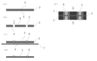
- FIG. 1 is a schematic cross-sectional view showing a method for manufacturing a multilayer substrate according to an embodiment of the present invention.
- FIG. 3 is a schematic cross-sectional view showing another method of manufacturing a multilayer substrate according to an embodiment of the present invention.
- the conductive paste according to the present embodiment includes (A) 100 parts by mass of a binder component containing 5 to 60 parts by mass of solid epoxy resin and 40 to 95 parts by mass of liquid epoxy resin, with the total amount not exceeding 100 parts by mass. to (B) 770 to 4300 parts by mass of spherical high melting point metal particles with a melting point of 800°C or higher, (C) 1510 to 5400 parts by mass of spherical low melting point metal particles with a melting point of 240°C or lower, and (D) a curing agent. 10 to 150 parts by mass of (E) flux, and 30 to 200 parts by mass of (E) flux.
- solid epoxy resin refers to an epoxy resin that does not have fluidity in a solvent-free state at room temperature (23° C.).
- the solid epoxy resin is not particularly limited as long as it contains an epoxy group in the molecule and is solid at room temperature (23°C), but specific examples include trisphenol type epoxy resin, trisphenolmethane type epoxy resin, Bisphenol type epoxy resins (e.g., bisphenol A type epoxy resin, bisphenol F type epoxy resin, bisphenol S type epoxy resin), naphthalene type epoxy resin, biphenyl type epoxy resin, terpene type epoxy resin, phenol novolac type epoxy resin, etc. . These may be used alone or in combination of two or more. Further, the solid epoxy resin may be used after being dissolved in a solvent.
- liquid epoxy resin refers to an epoxy resin that has fluidity in a solvent-free state at room temperature (23° C.).
- the liquid epoxy resin is not particularly limited as long as it contains an epoxy group in its molecule and is liquid at room temperature (23°C), but specific examples include bisphenol-type epoxy resins (e.g., bisphenol A-type epoxy resins, Bisphenol F type epoxy resin), glycidylamine-based epoxy resin, glycidyl ether-based epoxy resin, rubber-modified epoxy resin, and the like. These may be used alone or in combination of two or more.
- the liquid epoxy resin is preferably a bisphenol-type epoxy resin, a rubber-modified epoxy resin, or a glycidyl ether-based epoxy resin, and more preferably a combination of a bisphenol-type epoxy resin and a rubber-modified epoxy resin.
- rubber-modified epoxy resin refers to the above-mentioned liquid epoxy resin in which a rubber component is dispersed.
- the rubber components include butadiene rubber (BR), acrylic rubber (ACM), silicone rubber, butyl rubber (IIR), isoprene rubber (IR), chloroprene rubber (CR), nitrile rubber (NBR), and styrene-butadiene rubber (SBR), ethylene propylene rubber (EPR), etc.
- BR butadiene rubber
- ACM acrylic rubber
- IIR isoprene rubber
- CR chloroprene rubber
- NBR nitrile rubber
- SBR styrene-butadiene rubber
- EPR ethylene propylene rubber
- the above rubber components may be used alone or in combination of two or more.
- the content of the solid epoxy resin is preferably 5 to 60 parts by weight, more preferably 10 to 55 parts by weight, and even more preferably 15 to 50 parts by weight, based on 100 parts by weight of the binder component. When the content of the solid epoxy resin is within the above range, excellent conductivity and adhesiveness are likely to be obtained.
- the content of the liquid epoxy resin is preferably 40 to 95 parts by weight, more preferably 45 to 90 parts by weight, and even more preferably 50 to 85 parts by weight, based on 100 parts by weight of the binder component.
- the rubber-modified epoxy resin is preferably contained in a proportion of 1 to 50 parts by mass, more preferably 5 to 45 parts by mass, as a liquid epoxy resin in 100 parts by mass of the binder component. .
- the content ratio of the solid epoxy resin and the liquid epoxy resin is not particularly limited, but the mass ratio (solid/liquid) is preferably 0.05 to 1.5, and preferably 0.1 to 1.2. is more preferable. When the content ratio of the solid epoxy resin and the liquid epoxy resin is within the above range, excellent conductivity and adhesiveness are likely to be obtained.
- the weight average molecular weight of the solid epoxy resin is not particularly limited, but is preferably from 900 to 60,000, more preferably from 1,000 to 55,000, even more preferably from 1,200 to 50,000.
- weight average molecular weight can be measured by gel permeation chromatography (GPC), and is a value calculated using tetrahydrofuran as a mobile phase and a polystyrene equivalent calibration curve. shall be.
- the weight average molecular weight of the liquid epoxy resin is not particularly limited, but is preferably from 150 to 500, more preferably from 180 to 450, even more preferably from 200 to 400.
- the epoxy equivalent of the solid epoxy resin is not particularly limited, but is preferably from 150 to 10,000 g/eq, more preferably from 200 to 9,000 g/eq, even more preferably from 250 to 8,000 g/eq.
- the epoxy equivalent of the liquid epoxy resin is not particularly limited, but is preferably 90 to 500 g/eq, more preferably 100 to 450 g/eq, and even more preferably 120 to 400 g/eq.
- epoxy equivalent is measured according to JIS K7236:2009.
- the content of the spherical high melting point metal particles (B) having a melting point of 800°C or higher is 770 to 4300 parts by mass, preferably 900 to 4000 parts by mass, and 1000 to 3800 parts by mass, based on 100 parts by mass of the binder component. It is more preferable that When the content of the spherical high melting point metal particles (B) is within the above range, excellent electrical conductivity is likely to be obtained.
- Examples of the spherical high melting point metal particles (B) include silver particles, silver-coated copper particles, silver-coated copper alloy particles, and the like.
- the silver-coated copper particles are not particularly limited as long as they include copper particles and a silver-containing layer that covers at least a portion of the copper particles.
- the silver-coated copper alloy particles are not particularly limited as long as they include copper alloy particles and a silver-containing layer that covers at least a portion of the copper alloy particles.
- the copper alloy particles contain 0.5 to 25% by mass of zinc and/or 0.5 to 30% by mass of nickel, with the balance consisting of copper, and the remaining copper may contain unavoidable impurities.
- the content of the silver-containing layer in the silver-coated copper particles and the silver-coated copper alloy particles is not particularly limited, but is preferably 4 to 24% by mass. Although the silver content in the silver-containing layer is not particularly limited, it is preferably 90 to 100% by mass.
- the average particle diameter of the spherical high melting point metal particles (B) is not particularly limited, but is preferably 0.5 to 20 ⁇ m, more preferably 1 to 10 ⁇ m.
- the "average particle diameter” means the particle diameter (primary particle diameter) at 50% of the integrated value in the particle size distribution obtained by the laser diffraction scattering method.
- the content of the spherical low melting point metal particles (C) with a melting point of 240° C. or less is 1510 to 5400 parts by mass, preferably 1600 to 5200 parts by mass, and 1900 to 5000 parts by mass based on 100 parts by mass of the binder component. It is more preferable that When the content of the spherical low melting point metal particles (C) is within the above range, excellent electrical conductivity is likely to be obtained.
- the spherical low melting point metal particles (C) were selected from the group consisting of tin (melting point: 231°C), lead (melting point: 327°C), bismuth (melting point: 271°C), and indium (melting point: 156°C).
- An alloy made of two or more types can be used.
- the average particle diameter of the spherical low melting point metal particles (C) is not particularly limited, but is preferably 1 to 20 ⁇ m, more preferably 2 to 10 ⁇ m.
- the upper limit of the melting point of the spherical high melting point metal particles (B) is not particularly limited as long as it is 800°C or higher.
- the melting point of the spherical high melting point metal particles (B) may be, for example, 800 to 1460°C.
- the lower limit of the melting point of the spherical low-melting metal particles (C) is not particularly limited as long as it is 240° C. or lower.
- the melting point of the spherical low melting point metal particles (C) may be, for example, 130 to 235°C.
- the content ratio of the spherical high melting point metal particles (B) and the spherical low melting point metal particles (C) is preferably 0.25 to 2 in terms of mass ratio ((B)/(C)), and 0.4 to 2. More preferably, it is 1.5.
- the content of the curing agent (D) is 10 to 150 parts by weight, preferably 15 to 140 parts by weight, and more preferably 20 to 130 parts by weight, based on 100 parts by weight of the binder component.
- the content of the curing agent (D) is within the above range, excellent conductivity and adhesiveness are likely to be obtained.
- the curing agent (D) is not particularly limited, but an isocyanate curing agent, a cationic curing agent, or a phenol curing agent can be used. These may be used alone or in combination of two or more.
- Examples of the isocyanate curing agent include lower aliphatic polyisocyanates such as 1,2-ethylene diisocyanate, 1,4-butylene diisocyanate, and 1,6-hexamethylene diisocyanate; cyclopentylene diisocyanate, cyclohexylene diisocyanate, and isophorone diisocyanate. , alicyclic polyisocyanates such as hydrogenated tolylene diisocyanate and hydrogenated xylylene diisocyanate; aromas such as 2,4-tolylene diisocyanate, 2,6-tolylene diisocyanate, 4,4'-diphenylmethane diisocyanate, xylylene diisocyanate, etc. Examples thereof include group polyisocyanates, and block isocyanates obtained by reacting polyisocyanates with a sealant such as phenol may also be used.
- the blocked isocyanate one prepared by blocking polyisocyanate with a sealant can be used.
- polyisocyanates include aliphatic diisocyanates such as hexamethylene diisocyanate (including trimers), tetramethylene diisocyanate, and trimethylhexamethylene diisocyanate; Cyclic polyisocyanates; Aromatic diisocyanates such as 4,4'-diphenylmethane diisocyanate, tolylene diisocyanate, and xylylene diisocyanate; Modified products of these diisocyanates (urethanized products, carbodiimides, uretdiones, uretonimines, biurets, and/or isocyanurate modifications) things, etc.); These may be used alone or in combination of two or more.
- sealants include monohydric alkyl (or aromatic) alcohols such as n-butanol, n-hexyl alcohol, 2-ethylhexanol, lauryl alcohol, phenol carbinol, methylphenyl carbinol; ethylene glycol mono Cellosolves such as hexyl ether, ethylene glycol mono-2-ethylhexyl ether; polyether-type double-terminated diols such as polyethylene glycol, polypropylene glycol, polytetramethylene ether glycol phenol; ethylene glycol, propylene glycol, 1,4-butanediol, etc.
- monohydric alkyl (or aromatic) alcohols such as n-butanol, n-hexyl alcohol, 2-ethylhexanol, lauryl alcohol, phenol carbinol, methylphenyl carbinol
- ethylene glycol mono Cellosolves such as hexyl ether
- polyester-type double-terminated polyols obtained from diols and dicarboxylic acids such as oxalic acid, succinic acid, adipic acid, suberic acid, and sebacic acid; phenols such as para-t-butylphenol and cresol; dimethyl ketoxime, methyl ethyl ketox Oximes such as oxime, methylisobutylketoxime, methylamylketoxime, and cyclohexanoneoxime; pyrazoles such as dimethylpyrazole; and lactams represented by ⁇ -caprolactam and ⁇ -butyrolactam are preferably used. These may be used alone or in combination of two or more.
- Examples of the cationic curing agent include amine salts of boron trifluoride, p-methoxybenzenediazonium hexafluorophosphate, diphenyliodonium hexafluorophosphate, triphenylsulfonium, tri-n-octylphosphine oxide, and tetra- Examples include onium compounds represented by n-butylphosphonium tetraphenylborate, tetra-n-butylphosphonium benzotriazolate, tetra-n-butylphosphonium-o,o-diethylphosphorodithioate, and the like.
- phenolic curing agent examples include novolac phenol, naphthol compounds, and the like.
- the content of flux (E) is 30 to 200 parts by weight, preferably 40 to 180 parts by weight, and more preferably 50 to 160 parts by weight, based on 100 parts by weight of the binder component.
- the flux (E) content is 30 parts by mass or more, metallization of the conductive paste tends to occur, and when it is 200 parts by mass or less, excellent conductivity is easily obtained.
- the flux (E) promotes melting of the low melting point metal particles and mutual integration with the high melting point metal particles.
- the flux include zinc chloride, lactic acid, citric acid, oleic acid, stearic acid, glutamic acid, benzoic acid, oxalic acid, glutamic acid hydrochloride, aniline hydrochloride, cetylpyridine bromide, urea, triethanolamine, hydroxyethyl lauryl.
- Examples include amine, glycerin, hydrazine, 8-ethyl octadecanedioic acid, rosin and the like.
- the conductive paste of the present invention can be obtained by blending the above-mentioned components in predetermined amounts and thoroughly mixing them.
- additives that have conventionally been added to the same type of conductive paste can also be added to the conductive paste of the present invention within a range that does not depart from the purpose of the present invention.
- examples include antifoaming agents, thickeners, tackifiers, antioxidants, plasticizers, ultraviolet absorbers, fillers, flame retardants, organic solvents, and the like.
- the viscosity of the conductive paste of the present invention is preferably 50 to 300 Pa ⁇ s, more preferably 100 to 250 Pa ⁇ s.
- viscosity refers to rotor No. 1 using a B-type viscometer. 7. The value is taken 1 minute after the start of measurement, measured under the conditions of a rotation speed of 10 rpm and a measurement temperature of 25°C.
- the conductive paste according to this embodiment is optimal for use in filling holes in multilayer substrates.
- the method for manufacturing the multilayer substrate according to an embodiment of the present invention is not particularly limited, it can be manufactured by, for example, the following method.
- a prepreg 3 is laminated on a substrate 1 in which a through hole 2 is formed, and a PET film 4 is laminated thereon.
- holes 5 penetrating the PET film 4 and the prepreg 3 are formed by irradiating with a CO 2 laser.
- the prepreg 3 in which the holes 5 are formed is subjected to plasma treatment.
- the hole 5 is filled with a conductive paste 6.
- the PET film 4 is peeled off.
- a multilayer substrate 8 is obtained by laminating the substrate 1 on the prepreg 3 and hot pressing in the direction of the arrow.
- the multilayer substrate according to an embodiment of the present invention can also be manufactured by the following method.
- PET films 4 are laminated on both sides of the prepreg 3.
- a CO 2 laser is irradiated to form a hole 5 penetrating the PET film 4 and the prepreg 3.
- the prepreg with holes 5 is placed on top of clean room dust-free paper 7, and the holes 5 are filled with conductive paste 6.
- the PET film 4 is peeled off.
- a multilayer substrate 8 is obtained by laminating two substrates 1 so as to sandwich the prepreg 3 therebetween and hot pressing in the direction of the arrow.
- each component was mixed to prepare a conductive paste.
- average particle size 5 ⁇ m
- Blocked isocyanate curing agent Blocked isocyanate curing agent, "Coronate 2554" manufactured by Tosoh Corporation ⁇ Flux: Hydroxyethyl laurylamine
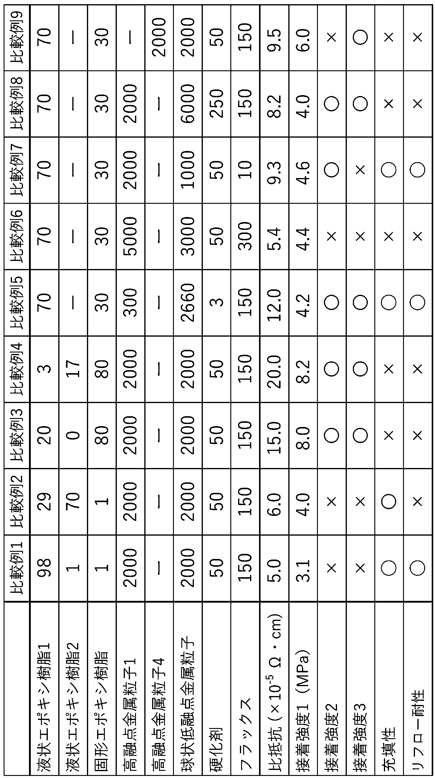
- the conductivity, adhesive strength, fillability, and reflow resistance of the obtained conductive paste were measured, and the results are shown in Tables 1 and 2.
- the measurement method is as shown below.
- ⁇ Adhesive strength 1> The above conductive paste was printed (length 12 mm, width 25 mm, thickness approximately 100 ⁇ m) on part of two copper plates (length 100 mm x 25 mm x 1 mm), the pastes were bonded together, and the paste was heated at 180°C for 60 minutes. The adhesive was cured by heating to prepare an adhesive strength sample. Next, the tensile shear strength was measured using a precision universal testing machine Autobluff AGX-V series (manufactured by Shimadzu Corporation). If the shear strength was 5 MPa or more, it was evaluated as being excellent in adhesive strength 1.
- ⁇ Adhesive strength 2 after heat cycle test> After 1000 cycles of a heat cycle test in which the adhesive strength sample was treated at -60° C. for 30 minutes and at 125° C. for 30 minutes, the tensile shear strength was measured, and the rate of change from the tensile shear strength before the test was calculated. If the rate of change is within ⁇ 10%, it is evaluated to be excellent in adhesive strength 2 and indicated as " ⁇ " in Tables 1 and 2, and if the rate of change is greater than ⁇ 10%, it is evaluated to be inferior to adhesive strength 2. The results are indicated as " ⁇ " in Tables 1 and 2.
- ⁇ Adhesive strength 3 after moisture resistance test> After the adhesive strength sample was allowed to stand for 1000 hours in an environment with a temperature of 85°C and a humidity of 85%, the tensile shear strength was measured, and the rate of change from the tensile shear strength before the test was calculated. If the rate of change is within ⁇ 10%, it is evaluated as being excellent in adhesive strength 3 and indicated as " ⁇ " in Tables 1 and 2. If the rate of change is greater than ⁇ 10%, it is evaluated as being inferior in adhesive strength 3. The results are indicated as " ⁇ " in Tables 1 and 2.
- a CO 2 laser was used to form a 169-hole connection pattern with a diameter of 100 ⁇ m on an insulating layer (manufactured by Panasonic Corporation, product name "R-1551”) with a thickness of about 100 ⁇ m, and the conductive paste was filled into the holes using a printing method.
- a substrate for evaluation was produced by pressing using a vacuum press machine under the following pressure conditions and temperature conditions. Pressure: The pressure was increased from 0 kg/cm 2 to a surface pressure of 10.2 kg/cm 2 over 17 minutes, and maintained as such for 10 minutes. Next, the surface pressure was increased to 30.6 kg/cm 2 over 24 minutes, maintained as such for 46 minutes, and then reduced to 0 kg/cm 2 over 23 minutes.
- the temperature was raised from 30°C to 130°C over 17 minutes and maintained at that temperature for 10 minutes. Next, the temperature was raised to 180°C over 24 minutes, maintained as such for 46 minutes, and then cooled to 30°C over 23 minutes.
- the hole portion of the evaluation substrate was observed using an X-ray transmission device (trade name: "Y.Cheetah ⁇ HD", manufactured by YXLON International) under the following measurement conditions. If there are any areas where the paste is not filled or if cracks occur during curing, the filling properties are evaluated as poor and are marked with an "x" in Tables 1 and 2.
- ⁇ Reflow resistance> The evaluation substrate prepared for evaluation of filling properties was treated in a reflow oven at 260°C for 10 seconds, which was repeated five times, and the hole resistance value was measured, and the hole resistance value from the evaluation substrate before the test was measured. The rate of change was calculated. Regarding the measurement of the resistance value, the resistance value between both ends of the connection pattern was measured, and the resistance value was divided by the number of holes to obtain the resistance value per hole, and the average value was calculated. For the samples after the reflow test, the average resistance value was determined in the same manner. The rate of change in resistance value before and after the reflow test is calculated using the following formula, where a is the resistance value measured before the test, and b is the resistance value measured after the test.
- Examples 1 to 10 are all excellent in conductivity, adhesive strength, fillability, and reflow resistance.
- Comparative Examples 1 and 2 are examples in which the content of liquid epoxy resin exceeds the upper limit and the content of solid epoxy resin is less than the lower limit, but Comparative Example 1 has poor adhesive strength, and Comparative Example 2 had poor adhesive strength and reflow resistance.
- Comparative Examples 3 and 4 are examples in which the content of liquid epoxy resin is less than the lower limit and the content of solid epoxy resin exceeds the upper limit, but Comparative Examples 3 and 4 have poor conductivity, fillability, and reflow resistance. was inferior.
- Comparative Example 5 is an example in which the content of high melting point metal particles and curing agent was less than the lower limit, but the conductivity and adhesive strength 1 were poor.
- Comparative Example 6 is an example in which the content of high melting point metal particles and flux exceeds the upper limit, but the adhesive strength, fillability, and reflow resistance were poor.
- Comparative Example 7 is an example in which the content of low melting point metal particles and flux was less than the lower limit, but adhesive strengths 1 and 3 were poor.
- Comparative Example 8 is an example in which the content of low melting point metal particles and curing agent exceeds the upper limit, but adhesive strength 1, fillability, and reflow resistance were poor.
- Comparative Example 9 is an example in which flaky metal particles were used as the high-melting point metal particles, and was inferior in adhesive strength 2, fillability, and reflow resistance.
Landscapes
- Physics & Mathematics (AREA)
- Chemical & Material Sciences (AREA)
- Dispersion Chemistry (AREA)
- Spectroscopy & Molecular Physics (AREA)
- Engineering & Computer Science (AREA)
- Microelectronics & Electronic Packaging (AREA)
- Conductive Materials (AREA)
Abstract
Description
[1] (A)固形エポキシ樹脂5~60質量部と、液状エポキシ樹脂40~95質量部とを合計量が100質量部を超えない範囲で含むバインダー成分100質量部に対し、(B)融点800℃以上の球状高融点金属粒子を770~4300質量部と、(C)融点240℃以下の球状低融点金属粒子を1510~5400質量部と、(D)硬化剤を10~150質量部と、(E)フラックスを30~200質量部とを含有する、導電性ペースト。
[2] 上記球状高融点金属粒子(B)が、銀粒子、銀被覆銅粒子、及び銀被覆銅合金粒子からなる群から選択される少なくとも1種を含有する、[1]に記載の導電性ペースト。
[3] 上記球状低融点金属粒子(C)が、錫、鉛、ビスマス及びインジウムからなる群から選択された2種以上の合金からなる、[1]又は[2]に記載の導電性ペースト。
[4] 前記液状エポキシ樹脂が、ビスフェノール型エポキシ樹脂、ゴム変性エポキシ樹脂、及びグリシジルエーテル系エポキシ樹脂からなる群から選択される少なくとも1種を含む、[1]~[3]のいずれか1項に記載の導電性ペースト。
[5] 前記球状高融点金属粒子(B)と前記球状低融点金属粒子(C)との質量比(B)/(C)が0.25~2である、[1]~[4]のいずれか1項に記載の導電性ペースト。
[6] 複数の導電層とこれら複数の導電層間に介在する絶縁層とからなり、上記絶縁層を貫通するホールが導電性ペースト硬化物により充填されており、この導電性ペースト硬化物を介して上記絶縁層の両面に接する導電層同士が相互に導通している多層基板であって、上記導電性ペースト硬化物が[1]~[5]のいずれか1項に記載の導電性ペーストの硬化物である、多層基板。
・液状エポキシ樹脂2:NBR変性エポキシ樹脂、(株)ADEKA製「EPR-1414-1」、エポキシ当量=400g/eq
・固形エポキシ樹脂:フェノールノボラック型エポキシ樹脂、三菱ケミカル(株)製「JER157S70」、エポキシ当量=200g/eq
・高融点金属粒子1:球状銀被覆銅粉、平均粒子径=5μm、銀の含有割合=10質量%、融点1073℃
・高融点金属粒子2:球状銀粉、平均粒子径=5μm、融点962℃
・高融点金属粒子3:球状銀被覆銅合金粉、平均粒子径=5μm、銀の含有割合=10質量%、銅合金粒子はニッケルを5質量%の割合で含む、融点1024℃
・高融点金属粒子4:フレーク状銀被覆銅粉、平均粒子径=5μm、銀の含有割合=10質量%、融点1073℃
・球状低融点金属粒子:Sn-Bi合金金属粒子(Sn:Bi=42:58、融点138℃)、平均粒子径=5μm
・硬化剤:ブロックイソシアネート硬化剤、東ソー(株)製「コロネート2554」
・フラックス:ヒドロキシエチルラウリルアミン
ガラスエポキシ基板上にメタル版を用いて実施例及び比較例で得られた上記導電性ペーストをライン印刷(長さ60mm、幅1mm、厚さ約100μm)し、180℃で60分間加熱することにより本硬化させ、導電性パターンが形成された評価用基板を作製した。次いで、テスターを用いて導電性パターンの両端間の抵抗値(R)を測定し、断面積(S、cm2)と長さ(L、cm)から下記式(1)により比抵抗を計算した。なお、ガラスエポキシ基板3枚に各5本のライン印刷を施して導電性パターンを合計15本形成し、それらの比抵抗の平均値を求めた。比抵抗が1×10⁻⁴Ω・cm未満であれば導電性に優れていると評価した。
比抵抗=(S/L)×R (1)
2枚の銅板(長さ100mm×25mm×1mm)の一部に上記導電性ペーストを印刷(長さ12mm、幅25mm、厚さ約100μm)し、ペースト同士を接着させて、180℃で60分間加熱することにより本硬化させ、接着強度サンプルを作製した。次に、精密万能試験機オートブラフAGX-Vシリーズ(島津製作所製)を用いて引っ張りせん断強度を測定した。せん断強度が5MPa以上であれば接着強度1に優れていると評価した。
上記接着強度サンプルを-60℃、30分間と125℃、30分間で処理するヒートサイクル試験1000サイクル後、引っ張りせん断強度を測定し、試験前の引っ張りせん断強度からの変化率を算出した。変化率が±10%以内の場合、接着強度2に優れていると評価し表1,2に「○」と示し、変化率が±10%より大きい場合、接着強度2に劣っていると評価し表1,2に「×」と示した。
上記接着強度サンプルを温度85℃、湿度85%の環境下で1000時間静置後、引っ張りせん断強度を測定し、試験前の引っ張りせん断強度からの変化率を算出した。変化率が±10%以内の場合、接着強度3に優れていると評価し表1,2に「○」と示し、変化率が±10%より大きい場合、接着強度3に劣っていると評価し表1,2に「×」と示した。
厚さ約100μmの絶縁層(パナソニック社製、商品名「R-1551」)にCO2レーザーを用いて、φ100μmの169孔連結パターンを形成し、印刷法により孔内に上記導電性ペーストを充填した後、真空プレス機を用いて次の圧力条件及び温度条件でプレスを行うことで評価用基板を作製した。
圧力:0kg/cm2から17分間かけて面圧10.2kg/cm2まで昇圧し、そのまま10分間保持した。次いで、24分間かけて面圧30.6kg/cm2まで昇圧し、そのまま46分間保持した後、23分間かけて0kg/cm2まで減圧した。
温度:30℃から17分間かけて130℃まで昇温し、そのまま10分間保持した。次いで、24分間かけて180℃まで昇温し、そのまま46分間保持した後、23分間かけて30℃まで冷却した。
上記評価用基板をX線透過装置(商品名「Y.Cheetah μHD」、エクスロン・インターナショナル社製)を用いて、以下の測定条件にて孔部分を観察した。ペーストが未充填な部分がある場合や、硬化時にクラックが発生した場合は、充填性に劣っていると評価し表1,2に「×」と示し、硬化時にクラックが発生せず、ペーストが十分に充填されている場合は、充填性に優れていると評価し表1,2に「○」と示した。
<測定条件>電圧:50kV、電流:80μA、電力:4W
充填性の評価で作製した評価用基板を260℃、10秒間のリフロー炉で処理することを5回繰り返した後の孔部抵抗値を測定し、試験前の評価用基板からの孔部抵抗値の変化率を算出した。抵抗値の測定については、上記連結パターンの両端間の抵抗値を測定し、その抵抗値を各孔数で除算し、1孔当たりの抵抗値を求め、平均値を算出した。リフロー試験後のサンプルについても、同様にして抵抗値の平均値を求めた。リフロー試験前後の抵抗値の変化率は、試験前に測定した抵抗値をa、試験後に測定した抵抗値をbとして、抵抗値変化率を次式により求め、変化率が±10%以内の場合、リフロー耐性に優れていると評価し表1,2に「○」と示し、変化率が±10%より大きい場合、リフロー耐性に劣っていると評価し表1,2に「×」と示した。
抵抗値変化率(%)=(b-a)×100/a

2・・・スルーホール
3・・・プリプレグ
4・・・PETフィルム
5・・・ホール
6・・・導電性ペースト
7・・・クリーンルーム用無塵紙
8・・・多層基板
Claims (6)
- (A)固形エポキシ樹脂5~60質量部と、液状エポキシ樹脂40~95質量部とを合計量が100質量部を超えない範囲で含むバインダー成分100質量部に対し、
(B)融点800℃以上の球状高融点金属粒子を770~4300質量部と、
(C)融点240℃以下の球状低融点金属粒子を1510~5400質量部と、
(D)硬化剤を10~150質量部と、
(E)フラックスを30~200質量部とを含有する、導電性ペースト。 - 前記球状高融点金属粒子(B)が、銀粒子、銀被覆銅粒子、及び銀被覆銅合金粒子からなる群から選択される少なくとも1種を含有する、請求項1に記載の導電性ペースト。
- 前記球状低融点金属粒子(C)が、錫、鉛、ビスマス及びインジウムからなる群から選択された2種以上の合金からなる、請求項1又は2に記載の導電性ペースト。
- 前記液状エポキシ樹脂が、ビスフェノール型エポキシ樹脂、ゴム変性エポキシ樹脂、及びグリシジルエーテル系エポキシ樹脂からなる群から選択される少なくとも1種を含む、請求項1~3のいずれか1項に記載の導電性ペースト。
- 前記球状高融点金属粒子(B)と前記球状低融点金属粒子(C)との質量比(B)/(C)が0.25~2である、請求項1~4のいずれか1項に記載の導電性ペースト。
- 複数の導電層とこれら複数の導電層間に介在する絶縁層とからなり、前記絶縁層を貫通するホールが導電性ペースト硬化物により充填されており、この導電性ペースト硬化物を介して前記絶縁層の両面に接する導電層同士が相互に導通している多層基板であって、
前記導電性ペースト硬化物が請求項1~5のいずれか1項に記載の導電性ペーストの硬化物である、多層基板。
Priority Applications (2)
| Application Number | Priority Date | Filing Date | Title |
|---|---|---|---|
| CN202380060702.6A CN119744424A (zh) | 2022-09-01 | 2023-08-30 | 导电性糊剂及使用了该导电性糊剂的多层基板 |
| JP2024544317A JPWO2024048628A1 (ja) | 2022-09-01 | 2023-08-30 |
Applications Claiming Priority (2)
| Application Number | Priority Date | Filing Date | Title |
|---|---|---|---|
| JP2022-139203 | 2022-09-01 | ||
| JP2022139203 | 2022-09-01 |
Publications (1)
| Publication Number | Publication Date |
|---|---|
| WO2024048628A1 true WO2024048628A1 (ja) | 2024-03-07 |
Family
ID=90099683
Family Applications (1)
| Application Number | Title | Priority Date | Filing Date |
|---|---|---|---|
| PCT/JP2023/031411 Ceased WO2024048628A1 (ja) | 2022-09-01 | 2023-08-30 | 導電性ペースト、及びこれを用いた多層基板 |
Country Status (4)
| Country | Link |
|---|---|
| JP (1) | JPWO2024048628A1 (ja) |
| CN (1) | CN119744424A (ja) |
| TW (1) | TW202414442A (ja) |
| WO (1) | WO2024048628A1 (ja) |
Citations (5)
| Publication number | Priority date | Publication date | Assignee | Title |
|---|---|---|---|---|
| JP2002201448A (ja) * | 2000-12-27 | 2002-07-19 | Ricoh Co Ltd | 導電性接着剤 |
| JP2008108629A (ja) * | 2006-10-26 | 2008-05-08 | Tatsuta System Electronics Kk | 導電性ペースト及びこれを用いた多層基板 |
| WO2015174299A1 (ja) * | 2014-05-14 | 2015-11-19 | 積水化学工業株式会社 | 導電ペースト、導電ペーストの製造方法、接続構造体及び接続構造体の製造方法 |
| WO2017138256A1 (ja) * | 2016-02-10 | 2017-08-17 | 古河電気工業株式会社 | 導電性接着剤組成物ならびにこれを用いた導電性接着フィルムおよびダイシング・ダイボンディングフィルム |
| WO2022034696A1 (ja) * | 2020-08-11 | 2022-02-17 | タツタ電線株式会社 | 導電性組成物 |
-
2023
- 2023-05-26 TW TW112119766A patent/TW202414442A/zh unknown
- 2023-08-30 JP JP2024544317A patent/JPWO2024048628A1/ja active Pending
- 2023-08-30 WO PCT/JP2023/031411 patent/WO2024048628A1/ja not_active Ceased
- 2023-08-30 CN CN202380060702.6A patent/CN119744424A/zh active Pending
Patent Citations (5)
| Publication number | Priority date | Publication date | Assignee | Title |
|---|---|---|---|---|
| JP2002201448A (ja) * | 2000-12-27 | 2002-07-19 | Ricoh Co Ltd | 導電性接着剤 |
| JP2008108629A (ja) * | 2006-10-26 | 2008-05-08 | Tatsuta System Electronics Kk | 導電性ペースト及びこれを用いた多層基板 |
| WO2015174299A1 (ja) * | 2014-05-14 | 2015-11-19 | 積水化学工業株式会社 | 導電ペースト、導電ペーストの製造方法、接続構造体及び接続構造体の製造方法 |
| WO2017138256A1 (ja) * | 2016-02-10 | 2017-08-17 | 古河電気工業株式会社 | 導電性接着剤組成物ならびにこれを用いた導電性接着フィルムおよびダイシング・ダイボンディングフィルム |
| WO2022034696A1 (ja) * | 2020-08-11 | 2022-02-17 | タツタ電線株式会社 | 導電性組成物 |
Also Published As
| Publication number | Publication date |
|---|---|
| TW202414442A (zh) | 2024-04-01 |
| JPWO2024048628A1 (ja) | 2024-03-07 |
| CN119744424A (zh) | 2025-04-01 |
Similar Documents
| Publication | Publication Date | Title |
|---|---|---|
| US8133412B2 (en) | Anisotropic conductive film | |
| JP6967726B2 (ja) | はんだペーストおよび実装構造体 | |
| EP2357876A1 (en) | Electroconductive connecting material, method for connecting terminals to each other using the electroconductive connecting material, and method for manufacturing connecting terminal | |
| EP3279261B1 (en) | Resin composition, electroconductive resin composition, adhesive, electroconductive adhesive, paste for forming electrodes, and semiconductor device | |
| EP2178094A1 (en) | Circuit connection material, and connection structure of circuit member and connection method of circuit member using the circuit connection material | |
| TWI599636B (zh) | 導電性接著劑組成物及使用其之電子元件 | |
| EP2484739A1 (en) | Conductive connection material, method for connection between terminals and method for manufacturing connecting terminal | |
| JP5441954B2 (ja) | 回路接続用接着フィルム、これを用いた回路接続構造体及び回路部材の接続方法 | |
| JP7509179B2 (ja) | 導電粒子、回路接続材料、接続構造体及びその製造方法 | |
| EP2287262A1 (en) | Connecting material | |
| DE69722196T2 (de) | Leitfähiger Epoxidharzklebstoff mit verbessertem Fallwiderstand | |
| WO2024048628A1 (ja) | 導電性ペースト、及びこれを用いた多層基板 | |
| KR101100575B1 (ko) | 접착 필름, 및 회로 부재의 접속 구조 및 접속 방법 | |
| JP2005132854A (ja) | 導電性接着剤組成物 | |
| JP2024152781A (ja) | 導電性接着剤、回路接続構造体の製造方法及び回路接続構造体 | |
| JP7249549B2 (ja) | 樹脂組成物およびこれを含む異方性導電フィルム、並びに電子装置 | |
| JP7754606B2 (ja) | エポキシ樹脂組成物 | |
| JP2019054105A (ja) | 電極の接続方法および電子基板の製造方法 | |
| WO2022215486A1 (ja) | 導電性組成物 | |
| US20240409791A1 (en) | Electroconductive composition | |
| CN119855857A (zh) | 导电性组合物 | |
| WO2023067910A1 (ja) | 導電性組成物 | |
| JP5934823B1 (ja) | 熱硬化性接着剤樹脂組成物、接着剤フィルム、カバーレイフィルム、金属張積層板及びフレキシブルプリント配線板 | |
| JP2012244075A (ja) | 導電性樹脂組成物および多層配線基板 | |
| HK1147849A (en) | Anisotropic electroconductive film |
Legal Events
| Date | Code | Title | Description |
|---|---|---|---|
| 121 | Ep: the epo has been informed by wipo that ep was designated in this application |
Ref document number: 23860390 Country of ref document: EP Kind code of ref document: A1 |
|
| WWE | Wipo information: entry into national phase |
Ref document number: 2024544317 Country of ref document: JP |
|
| WWE | Wipo information: entry into national phase |
Ref document number: 202380060702.6 Country of ref document: CN |
|
| WWP | Wipo information: published in national office |
Ref document number: 202380060702.6 Country of ref document: CN |
|
| NENP | Non-entry into the national phase |
Ref country code: DE |
|
| 122 | Ep: pct application non-entry in european phase |
Ref document number: 23860390 Country of ref document: EP Kind code of ref document: A1 |