WO2024048115A1 - 水処理システムおよび水処理方法 - Google Patents
水処理システムおよび水処理方法 Download PDFInfo
- Publication number
- WO2024048115A1 WO2024048115A1 PCT/JP2023/026652 JP2023026652W WO2024048115A1 WO 2024048115 A1 WO2024048115 A1 WO 2024048115A1 JP 2023026652 W JP2023026652 W JP 2023026652W WO 2024048115 A1 WO2024048115 A1 WO 2024048115A1
- Authority
- WO
- WIPO (PCT)
- Prior art keywords
- edi
- membrane
- water
- water treatment
- chamber
- Prior art date
- Legal status (The legal status is an assumption and is not a legal conclusion. Google has not performed a legal analysis and makes no representation as to the accuracy of the status listed.)
- Ceased
Links
Images


Classifications
-
- C—CHEMISTRY; METALLURGY
- C02—TREATMENT OF WATER, WASTE WATER, SEWAGE, OR SLUDGE
- C02F—TREATMENT OF WATER, WASTE WATER, SEWAGE, OR SLUDGE
- C02F9/00—Multistage treatment of water, waste water or sewage
-
- B—PERFORMING OPERATIONS; TRANSPORTING
- B01—PHYSICAL OR CHEMICAL PROCESSES OR APPARATUS IN GENERAL
- B01D—SEPARATION
- B01D61/00—Processes of separation using semi-permeable membranes, e.g. dialysis, osmosis or ultrafiltration; Apparatus, accessories or auxiliary operations specially adapted therefor
- B01D61/42—Electrodialysis; Electro-osmosis ; Electro-ultrafiltration; Membrane capacitive deionization
- B01D61/422—Electrodialysis
- B01D61/423—Electrodialysis comprising multiple electrodialysis steps
-
- B—PERFORMING OPERATIONS; TRANSPORTING
- B01—PHYSICAL OR CHEMICAL PROCESSES OR APPARATUS IN GENERAL
- B01D—SEPARATION
- B01D61/00—Processes of separation using semi-permeable membranes, e.g. dialysis, osmosis or ultrafiltration; Apparatus, accessories or auxiliary operations specially adapted therefor
- B01D61/42—Electrodialysis; Electro-osmosis ; Electro-ultrafiltration; Membrane capacitive deionization
- B01D61/44—Ion-selective electrodialysis
-
- B—PERFORMING OPERATIONS; TRANSPORTING
- B01—PHYSICAL OR CHEMICAL PROCESSES OR APPARATUS IN GENERAL
- B01D—SEPARATION
- B01D61/00—Processes of separation using semi-permeable membranes, e.g. dialysis, osmosis or ultrafiltration; Apparatus, accessories or auxiliary operations specially adapted therefor
- B01D61/42—Electrodialysis; Electro-osmosis ; Electro-ultrafiltration; Membrane capacitive deionization
- B01D61/44—Ion-selective electrodialysis
- B01D61/46—Apparatus therefor
- B01D61/463—Apparatus therefor comprising the membrane sequence AC or CA, where C is a cation exchange membrane
-
- B—PERFORMING OPERATIONS; TRANSPORTING
- B01—PHYSICAL OR CHEMICAL PROCESSES OR APPARATUS IN GENERAL
- B01D—SEPARATION
- B01D61/00—Processes of separation using semi-permeable membranes, e.g. dialysis, osmosis or ultrafiltration; Apparatus, accessories or auxiliary operations specially adapted therefor
- B01D61/58—Multistep processes
-
- C—CHEMISTRY; METALLURGY
- C02—TREATMENT OF WATER, WASTE WATER, SEWAGE, OR SLUDGE
- C02F—TREATMENT OF WATER, WASTE WATER, SEWAGE, OR SLUDGE
- C02F1/00—Treatment of water, waste water, or sewage
- C02F1/42—Treatment of water, waste water, or sewage by ion-exchange
-
- C—CHEMISTRY; METALLURGY
- C02—TREATMENT OF WATER, WASTE WATER, SEWAGE, OR SLUDGE
- C02F—TREATMENT OF WATER, WASTE WATER, SEWAGE, OR SLUDGE
- C02F1/00—Treatment of water, waste water, or sewage
- C02F1/44—Treatment of water, waste water, or sewage by dialysis, osmosis or reverse osmosis
-
- C—CHEMISTRY; METALLURGY
- C02—TREATMENT OF WATER, WASTE WATER, SEWAGE, OR SLUDGE
- C02F—TREATMENT OF WATER, WASTE WATER, SEWAGE, OR SLUDGE
- C02F1/00—Treatment of water, waste water, or sewage
- C02F1/46—Treatment of water, waste water, or sewage by electrochemical methods
- C02F1/469—Treatment of water, waste water, or sewage by electrochemical methods by electrochemical separation, e.g. by electro-osmosis, electrodialysis, electrophoresis
-
- B—PERFORMING OPERATIONS; TRANSPORTING
- B01—PHYSICAL OR CHEMICAL PROCESSES OR APPARATUS IN GENERAL
- B01D—SEPARATION
- B01D2317/00—Membrane module arrangements within a plant or an apparatus
- B01D2317/02—Elements in series
- B01D2317/025—Permeate series
-
- B—PERFORMING OPERATIONS; TRANSPORTING
- B01—PHYSICAL OR CHEMICAL PROCESSES OR APPARATUS IN GENERAL
- B01D—SEPARATION
- B01D2317/00—Membrane module arrangements within a plant or an apparatus
- B01D2317/08—Use of membrane modules of different kinds
-
- B—PERFORMING OPERATIONS; TRANSPORTING
- B01—PHYSICAL OR CHEMICAL PROCESSES OR APPARATUS IN GENERAL
- B01D—SEPARATION
- B01D61/00—Processes of separation using semi-permeable membranes, e.g. dialysis, osmosis or ultrafiltration; Apparatus, accessories or auxiliary operations specially adapted therefor
- B01D61/02—Reverse osmosis; Hyperfiltration ; Nanofiltration
- B01D61/025—Reverse osmosis; Hyperfiltration
-
- B—PERFORMING OPERATIONS; TRANSPORTING
- B01—PHYSICAL OR CHEMICAL PROCESSES OR APPARATUS IN GENERAL
- B01D—SEPARATION
- B01D61/00—Processes of separation using semi-permeable membranes, e.g. dialysis, osmosis or ultrafiltration; Apparatus, accessories or auxiliary operations specially adapted therefor
- B01D61/02—Reverse osmosis; Hyperfiltration ; Nanofiltration
- B01D61/025—Reverse osmosis; Hyperfiltration
- B01D61/026—Reverse osmosis; Hyperfiltration comprising multiple reverse osmosis steps
-
- B—PERFORMING OPERATIONS; TRANSPORTING
- B01—PHYSICAL OR CHEMICAL PROCESSES OR APPARATUS IN GENERAL
- B01D—SEPARATION
- B01D61/00—Processes of separation using semi-permeable membranes, e.g. dialysis, osmosis or ultrafiltration; Apparatus, accessories or auxiliary operations specially adapted therefor
- B01D61/42—Electrodialysis; Electro-osmosis ; Electro-ultrafiltration; Membrane capacitive deionization
- B01D61/44—Ion-selective electrodialysis
- B01D61/46—Apparatus therefor
- B01D61/48—Apparatus therefor having one or more compartments filled with ion-exchange material, e.g. electrodeionisation
-
- C—CHEMISTRY; METALLURGY
- C02—TREATMENT OF WATER, WASTE WATER, SEWAGE, OR SLUDGE
- C02F—TREATMENT OF WATER, WASTE WATER, SEWAGE, OR SLUDGE
- C02F1/00—Treatment of water, waste water, or sewage
- C02F1/44—Treatment of water, waste water, or sewage by dialysis, osmosis or reverse osmosis
- C02F1/441—Treatment of water, waste water, or sewage by dialysis, osmosis or reverse osmosis by reverse osmosis
-
- C—CHEMISTRY; METALLURGY
- C02—TREATMENT OF WATER, WASTE WATER, SEWAGE, OR SLUDGE
- C02F—TREATMENT OF WATER, WASTE WATER, SEWAGE, OR SLUDGE
- C02F1/00—Treatment of water, waste water, or sewage
- C02F1/46—Treatment of water, waste water, or sewage by electrochemical methods
- C02F1/469—Treatment of water, waste water, or sewage by electrochemical methods by electrochemical separation, e.g. by electro-osmosis, electrodialysis, electrophoresis
- C02F1/4693—Treatment of water, waste water, or sewage by electrochemical methods by electrochemical separation, e.g. by electro-osmosis, electrodialysis, electrophoresis electrodialysis
- C02F1/4695—Treatment of water, waste water, or sewage by electrochemical methods by electrochemical separation, e.g. by electro-osmosis, electrodialysis, electrophoresis electrodialysis electrodeionisation
-
- C—CHEMISTRY; METALLURGY
- C02—TREATMENT OF WATER, WASTE WATER, SEWAGE, OR SLUDGE
- C02F—TREATMENT OF WATER, WASTE WATER, SEWAGE, OR SLUDGE
- C02F2101/00—Nature of the contaminant
- C02F2101/10—Inorganic compounds
- C02F2101/108—Boron compounds
-
- C—CHEMISTRY; METALLURGY
- C02—TREATMENT OF WATER, WASTE WATER, SEWAGE, OR SLUDGE
- C02F—TREATMENT OF WATER, WASTE WATER, SEWAGE, OR SLUDGE
- C02F2103/00—Nature of the water, waste water, sewage or sludge to be treated
- C02F2103/02—Non-contaminated water, e.g. for industrial water supply
- C02F2103/04—Non-contaminated water, e.g. for industrial water supply for obtaining ultra-pure water
-
- C—CHEMISTRY; METALLURGY
- C02—TREATMENT OF WATER, WASTE WATER, SEWAGE, OR SLUDGE
- C02F—TREATMENT OF WATER, WASTE WATER, SEWAGE, OR SLUDGE
- C02F2103/00—Nature of the water, waste water, sewage or sludge to be treated
- C02F2103/34—Nature of the water, waste water, sewage or sludge to be treated from industrial activities not provided for in groups C02F2103/12 - C02F2103/32
- C02F2103/346—Nature of the water, waste water, sewage or sludge to be treated from industrial activities not provided for in groups C02F2103/12 - C02F2103/32 from semiconductor processing, e.g. waste water from polishing of wafers
-
- C—CHEMISTRY; METALLURGY
- C02—TREATMENT OF WATER, WASTE WATER, SEWAGE, OR SLUDGE
- C02F—TREATMENT OF WATER, WASTE WATER, SEWAGE, OR SLUDGE
- C02F2301/00—General aspects of water treatment
- C02F2301/08—Multistage treatments, e.g. repetition of the same process step under different conditions
-
- Y—GENERAL TAGGING OF NEW TECHNOLOGICAL DEVELOPMENTS; GENERAL TAGGING OF CROSS-SECTIONAL TECHNOLOGIES SPANNING OVER SEVERAL SECTIONS OF THE IPC; TECHNICAL SUBJECTS COVERED BY FORMER USPC CROSS-REFERENCE ART COLLECTIONS [XRACs] AND DIGESTS
- Y02—TECHNOLOGIES OR APPLICATIONS FOR MITIGATION OR ADAPTATION AGAINST CLIMATE CHANGE
- Y02A—TECHNOLOGIES FOR ADAPTATION TO CLIMATE CHANGE
- Y02A20/00—Water conservation; Efficient water supply; Efficient water use
- Y02A20/124—Water desalination
- Y02A20/131—Reverse-osmosis
Definitions
- the present invention relates to a water treatment system and a water treatment method.
- Patent No. 4045658 Patent No. 5733351
- the boron removal rate using an RO membrane is low, and in the neutral range it is about 45 to 60% even when using an ultra-low pressure RO membrane.
- the boron removal rate will increase to about 80 to 90%, but this will lead to an increase in the power consumption of the pump.
- the pH of the water supplied to the RO membrane is adjusted to an alkaline side of 9 or higher, the boron removal rate will be improved, but this will require chemical injection equipment and replenishment management of chemicals. As a result, management costs also increase.
- addition of alkali promotes deterioration of the RO membrane. Therefore, there is also a concern that the frequency of replacing the RO membrane will increase.
- the above-mentioned technique has the problem that the boron removal rate cannot be improved without imposing a large load.
- An object of the present invention is to provide a water treatment system and a water treatment method that can improve the boron removal rate without imposing a large load.
- the water treatment system of the present invention includes: A water treatment system that removes at least boron contained in water to be treated, an RO membrane device including an extremely low pressure RO membrane; Arranged after the RO membrane device, the most downstream layer of the demineralization chamber is filled with at least an anion exchange resin, and the adjacent concentration chamber is filled with at least the cation exchange resin via a cation exchange membrane that partitions the demineralization chamber.
- EDI equipment including a high-purity EDI stack
- the RO membrane device is a two-stage RO membrane device, and the ultra-low pressure RO membrane is disposed in at least one of the first stage and the second stage.
- the water treatment method of the present invention includes: A water treatment method for removing at least boron contained in treated water, the method comprising:
- the boron concentration of the water to be treated supplied to the EDI equipment including the EDI stack for high purity is 20 to 100 [ ⁇ g/L]
- the silica concentration is 50 [ ⁇ g/L] or less
- the hardness is 0.05 [mgCaCO 3 /L].
- An RO membrane device including an extremely low pressure RO membrane device provided upstream of the EDI device is operated as follows.
- the boron removal rate can be improved without imposing a large load.
- FIG. 1 is a diagram showing a first embodiment of a water treatment system of the present invention.
- 2 is a diagram showing an example of the structure of the EDI device shown in FIG. 1.
- FIG. It is a figure showing the 2nd embodiment of the water treatment system of the present invention.
- 4 is a diagram showing an example of the structure of the general EDI device shown in FIG. 3.
- FIG. It is a figure showing the 3rd embodiment of the water treatment system of the present invention.
- It is a figure showing the 4th embodiment of the water treatment system of the present invention.
- It is a figure which shows the form of the 1st comparison for comparing with an Example.
- FIG. 3 is a diagram showing another example of the structure of a high-purity EDI device used in the present invention.
- the boron concentration is reported to be less than 0.5 [mg/L]. Furthermore, the average value in the water quality distribution table (raw water) of the Japan Water Works Association's water quality database (2019) (http://www.jwwa.or.jp/mizu/) indicates that the concentration of boron and its compounds is At points where the concentration is 0.1 [mg/L] or less, it is 99% in surface water and 97% in groundwater. For these reasons, the boron concentration range of raw water to which the present invention is applied is preferably 0.01 to 0.2 [mg/L], more preferably 0.02 to 0.1 [mg/L]. I am assuming that.
- the present invention provides a water treatment system that removes at least boron contained in water to be treated using an RO membrane (reverse osmosis membrane) device and an EDI device (electroregenerative deionized water production device) that are connected in series. It is.
- the EDI device is placed after the RO membrane device.
- An EDI device is a device that combines electrophoresis and electrodialysis. The configuration of the EDI device is such that a demineralization chamber partitioned by a pair of ion exchange membranes is disposed between an anode and a cathode.
- the demineralization chamber is filled with an ion exchange resin.
- the water to be treated is passed through the demineralization chamber while a DC voltage is applied between the anode and the cathode.
- the water to be treated is desalinated in the demineralization chamber, and the treated water from which ionic components have been removed flows out of the demineralization chamber.
- the configuration of the RO membrane device is a two-stage configuration (two-stage RO membrane device).
- the two-stage configuration of this RO membrane device includes, for example, a two-stage configuration of an extremely low pressure RO membrane device and an extremely low pressure RO membrane device, a two-stage configuration of an extremely low pressure RO membrane device and an extremely low pressure RO membrane device, and a two-stage configuration of an extremely low pressure RO membrane device and an extremely low pressure RO membrane device.
- one of the two stages may be an extremely low pressure RO membrane device and the other may be another RO membrane device such as a low pressure RO membrane device.
- Table 1 shows the water quality parameters of the water supplied to the EDI device (treated water of the RO membrane device) for each category.
- the supply water supplied to the EDI device is classified as Category A. Further, assuming a case where the configuration of the RO membrane device is such that an extremely low pressure RO membrane device is disposed after the ultra low pressure RO membrane device, the supply water supplied to the EDI device is classified as category B. Further, assuming a case where the configuration of the RO membrane device is such that an ultra-low pressure RO membrane device is disposed after the low pressure RO membrane device, the supply water supplied to the EDI device is classified as category C.
- the conductivity is 3 to 4 [ ⁇ S/cm]
- the boron concentration is 0.10 to 0.12 [mg/L]
- the sodium concentration is 0.5 to 0. 6 [mg/L]
- the concentration of silica is 0.04 to 0.06 [mg/L]
- the hardness is 0.04 to 0.05 [mgCaCO 3 /L].
- the conductivity is 2 to 3 [ ⁇ S/cm]
- the boron concentration is 0.02 to 0.03 [mg/L]
- the sodium concentration is 0.2 to 3 [ ⁇ S/cm].
- the silica concentration is 0.00 to 0.02 [mg/L]
- the hardness is 0.02 to 0.03 [mgCaCO 3 /L].
- the electrical conductivity is 1 to 2 [ ⁇ S/cm]
- the boron concentration is 0.005 to 0.01 [mg/L]
- the sodium concentration is 0.1 to 2 [ ⁇ S/cm].
- 0.15 [mg/L] the silica concentration is less than 0.005 [mg/L]
- the hardness is less than 0.01 [mgCaCO 3 /L].
- the concentration of boron contained in the raw water supplied to the RO membrane device placed in the first stage is 0.1 [mg/L]
- the boron removal rate in the configuration of Category A is 0%
- the boron removal rate in configuration B is 70 to 80%
- the boron removal rate in configuration C is 90 to 95%.
- the concentration of boron contained in the raw water supplied to the RO membrane device placed in the first stage is 0.2 [mg/L]
- the boron removal rate in the configuration of Category A is 40 to 50%.
- the boron removal rate in the configuration of Category B is 85 to 90%
- the boron removal rate in the configuration of Category C is 95 to 98%.
- a system was assumed in which alkali was added to the feed water line of the first stage low-pressure RO to adjust the pH of the concentrated water outlet to 10 to 11.
- the ultra-ultra-low-pressure RO membrane equipped in the ultra-ultra-low-pressure RO membrane device has a concentration of NaCl of 500 to 2000 [mg/L], a pH value of 6 to 8, and a water temperature of The salt removal rate measured under the conditions that the temperature is 25°C and a stock solution with a permeate recovery rate of 10 to 25% is supplied is less than 99.4%, and the supply pressure is 1 [MPa] and the membrane area is 1.
- the membrane has an amount of permeated water per [m 2 ] (permeated water flow rate per unit pressure/unit area) of 1.3 [(m 3 /d)/(m 2 ⁇ MPa)] or more.
- ultra-low pressure RO membranes include DuPont's XLE-440, XLE-440i, Hydranautics' ESPA4 (ESPA4-LD-4040, ESPA4-LD, ESPA4-LD HP, ESPA4MAX), Toray Industries, Inc.
- TMHA TMH10A, TMH20A-400C, TMH20A-440C
- An ultra-low pressure RO membrane is one in which the permeate flow rate per unit pressure and unit area is less than 1.3 [(m 3 /d)/(m 2 MPa)] under the same test conditions as above. Refers to a film with a removal rate of 99.3% or more.
- Examples of ultra-low pressure RO membranes include BW30HRLE-440 and SG30LE-440i manufactured by DuPont, ESPA2 MAX manufactured by Hydranautics, and TMG20D-400 manufactured by Toray Industries.
- a low-pressure RO membrane has a permeate flow rate per unit pressure and unit area of 0.8 [(m 3 /d)/(m 2 ⁇ MPa)] or less under the same test conditions as above, Refers to membranes with a salt removal rate of 99.5% or more.
- Examples of the low-pressure RO membrane include CR100 manufactured by DuPont. (Example 1)
- FIG. 1 is a diagram showing a first embodiment of the water treatment system of the present invention.
- RO membrane devices 10-1 and 10-2 and EDI devices 20-1 and 20-2 are connected in series.
- Each of the RO membrane devices 10-1 and 10-2 is an ultra-low pressure RO membrane device equipped with an ultra-low pressure type RO membrane.
- the EDI devices 20-1 and 20-2 are EDI devices for high purity.
- Raw water is supplied to the RO membrane apparatus 10-1 shown in FIG. 1, and the supplied raw water is processed in each of the RO membrane apparatuses 10-1 and 10-2 and the EDI apparatuses 20-1 and 20-2.
- the high-purity EDI device uses permeated water (boron concentration of 0.01 to 0.20 [mg/L] and water temperature of 20 to 28°C) that has been treated with a two-stage RO membrane.
- the EDI device has a boron removal rate of 99.0% or more when treated as water to be treated by the EDI device.
- the boron removal rate of the RO membrane device may be lower than when an ultra-low pressure, low-pressure, or high-pressure RO membrane device is installed. Conceivable. Therefore, EDI devices 20-1 and 20-2 including an EDI stack for high purity are installed as EDI devices downstream of the RO membrane devices 10-1 and 10-2.
- the most downstream layer of the demineralization chamber of the EDI device for high purity is filled with at least an anion exchange resin, and more preferably a single bed of anion exchange resin. Furthermore, the concentration chamber adjacent to the demineralization chamber via a cation exchange membrane is filled with at least a cation exchange resin, and more preferably is filled with a mixed bed of an anion exchange resin and a cation exchange resin. .
- FIG. 2 is a diagram showing an example of the structure of the EDI devices 20-1 and 20-2 shown in FIG. 1.
- the EDI devices 20-1 and 20-2 shown in FIG. 102, a concentration chamber 103, 104 which is a mixed bed (MB) filled with a cation exchange resin and an anion exchange resin, a first desalination chamber 105 filled with an anion exchange resin, and a cation exchange resin from upstream. and an anion exchange resin are provided in this order.
- Anode chamber 101 and concentration chamber 103 are adjacent to each other with cation exchange membrane 201 in between.
- Concentration chamber 103 and first demineralization chamber 105 are adjacent to each other with an anion exchange membrane 202 in between.
- the first demineralization chamber 105 and the second demineralization chamber 106 are adjacent to each other with an anion exchange membrane 202 in between.
- the second demineralization chamber 106 and the concentration chamber 104 are adjacent to each other with a cation exchange membrane 201 in between.
- Concentration chamber 104 and cathode chamber 102 are adjacent to each other with an anion exchange membrane 202 in between.
- the anode chamber 101 may also serve as the concentration chamber 103 without providing the cation exchange membrane 201 located between the anode chamber 101 and the concentration chamber 103.
- the anion exchange membrane 202 located between the cathode chamber 102 and the concentration chamber 104 may not be provided, and the cathode chamber 102 may also serve as the concentration chamber 104.
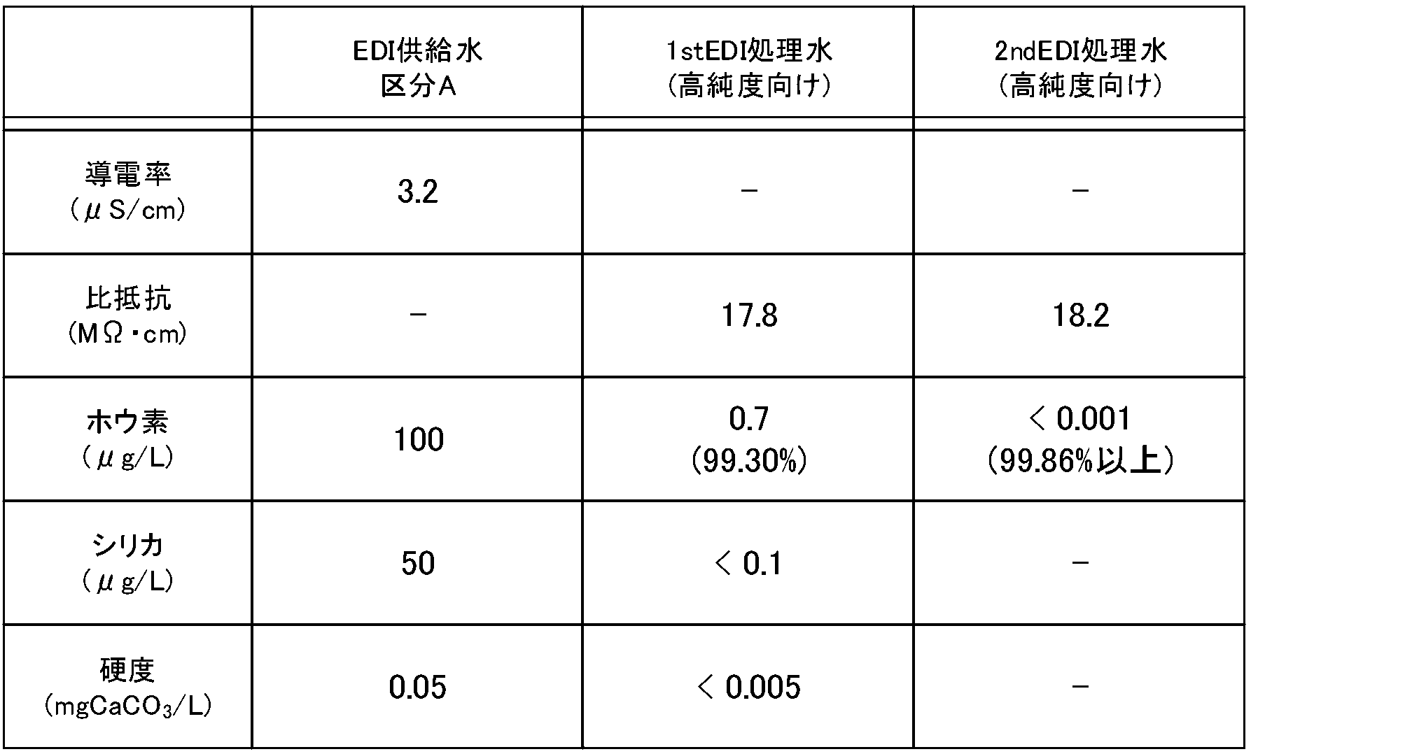
- Table 2 shows the results of water flow operation in the form of category A shown in FIG.
- XLE-440 which is an ultra-low pressure RO membrane manufactured by DuPont, is used, and three Water was passed through the elements arranged in parallel.
- the RO membrane device 10-1 was operated so that the flow rate of permeated water was 3.5 [m 3 /h], and the flow rate of permeated water in the RO membrane device 10-2 was 3.10 [m 3 /h].
- the EDI devices 20-1 and 20-2 include an anion exchange membrane 202, a first demineralization chamber 105, an anion exchange membrane 202, a second demineralization chamber 106, and a cation exchange membrane 201 shown in FIG.
- EDI stack for high purity in which 20 sets of basic configurations including the concentration chamber 104 were stacked, operation was performed under the following conditions of high flow rate and high current.
- the EDI device 20-1 which is the 1st EDI
- the flow rate (SV) per ion exchange resin volume in the first demineralization chamber 105 or the second demineralization chamber 106 is 440 [h -1 ]
- the current density is 1.2 [A/dm 2 ]
- the differential pressure in the demineralization chamber was 0.22 ⁇ 0.02 [MPa].
- the flow rate (SV) per volume of ion exchange resin in the first demineralization chamber 105 or the second demineralization chamber 106 is 400 [h -1 ], and the current It was operated under the conditions that the density was 1.2 [A/dm 2 ] and the differential pressure in the demineralization chamber was 0.20 ⁇ 0.02 [MPa].
- the high flow rate condition of the EDI stack is such that the flow rate (SV) per volume of ion exchange resin in the first demineralization chamber 105 or the second demineralization chamber 106 of the EDI devices 20-1 and 20-2 is 300 to 300.
- the water flow rate is 450 [h -1 ].
- the high current condition for the EDI stack is that a current with a current density of 0.8 to 1.2 [A/dm 2 ] be passed through the EDI devices 20-1 and 20-2.
- the conditions of high flow rate and high current of the EDI stack are conditions for water flow such that the water flow differential pressure in the demineralization chamber is 0.18 to 0.3 [MPa].
- the flow rate (SV) per volume of ion exchange resin in the first demineralization chamber 105 or the second demineralization chamber 106 of the EDI devices 20-1, 20-2 is 350 to 450 [h -1 ]. Let the water pass through.
- a current with a current density of 0.7 to 1.4 [A/dm 2 ] is passed through the EDI devices 20-1 and 20-2. Also, water is passed through the desalination chamber so that the water flow differential pressure is 0.18 to 0.3 [MPa].
- the EDI equipment for high purity is used as a two-stage configuration even in EDI feed water category A, which assumes RO treated water treated with a two-stage configuration of an extremely low pressure RO membrane device.
- the boron concentration can be reduced to the level required for ultrapure water by cutting-edge semiconductor manufacturers (less than 1 ng/L).
- FIG. 3 is a diagram showing a second embodiment of the water treatment system of the present invention.
- RO membrane devices 10-1 and 10-2 and EDI devices 21-1 and 20-2 are connected in series.
- the RO membrane devices 10-1, 10-2 and the EDI device 20-2 are the same as those in the first embodiment.
- the EDI device 21-1 is a general EDI device.
- Raw water is supplied to the RO membrane apparatus 10-1 shown in FIG. 3, and the supplied raw water is processed in each of the RO membrane apparatuses 10-1 and 10-2 and the EDI apparatuses 21-1 and 20-2.
- FIG. 4 is a diagram showing an example of the structure of the EDI device 21-1 shown in FIG. 3.
- the EDI device 21-1 shown in FIG. 3 includes an anode chamber 101 filled with cation exchange resin, a cathode chamber 102 filled with anion exchange resin, and Concentration chambers 107 and 108, a first demineralization chamber 105 filled with an anion exchange resin, and a second demineralization chamber 109 filled with a cation exchange resin are provided.
- Anode chamber 101 and concentration chamber 107 are adjacent to each other with cation exchange membrane 201 in between.
- the concentration chamber 107 and the first demineralization chamber 105 are adjacent to each other with an anion exchange membrane 202 in between.
- the first demineralization chamber 105 and the second demineralization chamber 109 are adjacent to each other with a cation exchange membrane 201 in between.
- the second demineralization chamber 109 and the concentration chamber 108 are adjacent to each other with a cation exchange membrane 201 in between.
- Concentration chamber 108 and cathode chamber 102 are adjacent to each other with an anion exchange membrane 202 in between.
- the anode chamber 101 may also serve as the concentration chamber 107 without providing the cation exchange membrane 201 located between the anode chamber 101 and the concentration chamber 107.
- the anion exchange membrane 202 located between the cathode chamber 102 and the concentration chamber 108 may not be provided, and the cathode chamber 102 may also serve as the concentration chamber 108.
- Table 3 shows the results of water flow operation in the form of category A shown in Figure 3.
- the operating conditions of each device are similar to those of Example 1.
- FIG. 5 is a diagram showing a third embodiment of the water treatment system of the present invention.
- RO membrane devices 10-1, 10-2, EDI device 20-1, and boron selective resin 30 are connected in series.
- the RO membrane devices 10-1, 10-2 and the EDI device 20-1 are the same as those in the first embodiment.
- the boron selective resin 30 is a device that selectively removes boron from the supplied liquid.
- the boron-selective resin 30 has a functional group that specifically reacts with boron, and can selectively remove boron.
- the boron-selective resin 30 is not particularly limited as long as it can selectively adsorb boron.
- the boron selective resin 30 an ion exchange resin or the like into which a polyhydric alcohol group is introduced as a functional group is used.
- the boron-selective resin 30 preferably has an N-methylglucamine group, which is a functional group having high selectivity for boron.
- examples of the boron-selective resin 30 include Amberlite IRA743 (manufactured by DuPont), Diaion CRB03 (manufactured by Mitsubishi Chemical Corporation), and the like.
- Raw water is supplied to the RO membrane device 10-1 shown in FIG. 5, and the supplied raw water is processed in each of the RO membrane devices 10-1, 10-2, EDI device 20-1, and boron selective resin 30. .
- Table 4 shows the results of water flow operation in the form of category A shown in Figure 5.
- the operating conditions of each device are similar to those of Example 1.
- FIG. 6 is a diagram showing a fourth embodiment of the water treatment system of the present invention.
- RO membrane devices 11-1 and 10-2 and EDI devices 21-1 and 20-2 are connected in series.
- the RO membrane device 10-2 and the EDI device 20-2 are the same as those in the first embodiment.
- the EDI device 21-1 is the same as that in the second embodiment.
- the RO membrane device 11-1 is a device equipped with an ultra-low pressure RO membrane.
- the RO membrane device 11-1 is, for example, an ultra-low pressure RO membrane (SG30LE-440i) manufactured by DuPont.
- Raw water is supplied to the RO membrane apparatus 11-1 shown in FIG. 6, and the supplied raw water is processed in each of the RO membrane apparatuses 11-1 and 10-2 and the EDI apparatuses 21-1 and 20-2.
- Table 5 shows the results of water flow operation in the form of category B shown in Figure 6.
- the operating conditions of each device are similar to those of Example 1.
- FIG. 7 is a diagram showing a first comparative form for comparison with the above-mentioned embodiment.
- RO membrane devices 10-1 and 10-2 and EDI devices 21-1 and 21-2 are connected in series.
- Each of the RO membrane devices 10-1 and 10-2 is the same as in the first embodiment.
- Each of the EDI devices 21-1 and 21-2 is the same as the EDI device 21-1 in the second embodiment.
- Raw water is supplied to the RO membrane apparatus 10-1 shown in FIG. 7, and the supplied raw water is processed in each of the RO membrane apparatuses 10-1 and 10-2 and the EDI apparatuses 21-1 and 21-2.
- Table 6 shows the results of water flow operation in the form of category A shown in FIG.
- three elements are arranged in parallel to each of the RO membrane devices 10-1 and 10-2, and water is passed through the RO membrane devices 10-1 and 10-2, and the permeated water flow rate of the RO membrane device 10-1 is 3.5 [m 3 /h],
- the RO membrane device 10-2 was operated so that the flow rate of permeated water was 3.10 [m 3 /h].
- each of the EDI devices 21-1 and 21-2 has 20 stacked sets of the basic configuration of the concentration chambers 107 and 108, the first demineralization chamber 105, and the second demineralization chamber 109 shown in FIG.
- the high-purity EDI stack was used and operated under the following conditions at high flow rate and high current.
- the flow rate (SV) per ion exchange resin volume in the first demineralization chamber 105 or the second demineralization chamber 109 is 440 [h -1 ], and the current density is 1.0 [A/dm 2 ] and the differential pressure in the demineralization chamber was 0.22 ⁇ 0.02 [MPa].
- the flow rate (SV) per volume of ion exchange resin in the first demineralization chamber 105 or the second demineralization chamber 109 is 400 [h -1 ], and the current It was operated under the conditions that the density was 1.0 [A/dm 2 ] and the differential pressure in the demineralization chamber was 0.20 ⁇ 0.02 [MPa].
- the concentration of boron contained in the treated water in the final stage EDI device 21-2 was 0.06 ⁇ g/L, and boron could be sufficiently removed from the raw water.
- the boron concentration cannot be reduced to the level of ultrapure water (less than 50 ng/L) required as a predetermined standard.
- FIG. 8 is a diagram showing a second comparison form for comparison with the above-described embodiment.
- RO membrane devices 12-1 and 11-2 and EDI devices 21-1 and 21-2 are connected in series.
- the RO membrane device 12-1 is a device equipped with a low-pressure RO membrane.
- the RO membrane device 12-1 is, for example, CR100 manufactured by DuPont.
- the RO membrane device 11-2 is the same as the RO membrane device 11-1 in the fourth embodiment.
- Each of the EDI devices 21-1 and 21-2 is the same as the EDI device 21-1 in the second embodiment.
- Raw water is supplied to the RO membrane device 12-1 shown in FIG. 8, and the supplied raw water is processed in each of the RO membrane devices 12-1, 11-2 and the EDI devices 21-1, 21-2. Note that a predetermined amount of sodium hydroxide is added to the raw water supplied to the RO membrane device 12-1.
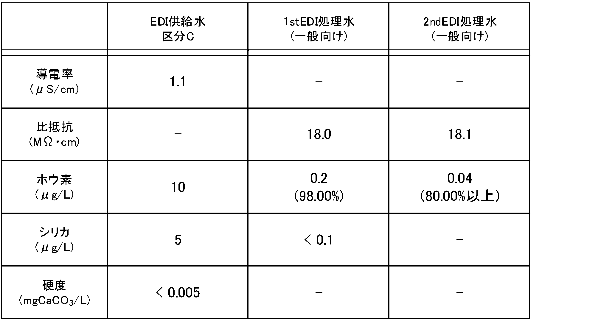
- Table 7 shows the results of water flow operation in the form of category C shown in FIG.
- three elements are arranged in parallel to each of the RO membrane devices 12-1 and 11-2, and water is passed through the RO membrane devices 12-1 and 11-2, and the permeated water flow rate of the RO membrane device 12-1 is 3.5 [m 3 /h], The RO membrane device 11-2 was operated so that the flow rate of permeated water was 3.10 [m 3 /h].
- each of the EDI devices 21-1 and 21-2 has 20 stacked sets of the basic configuration of the concentration chambers 107 and 108, the first demineralization chamber 105, and the second demineralization chamber 109 shown in FIG.
- the high-purity EDI stack was used and operated under the following conditions at high flow rate and high current.
- the flow rate (SV) per ion exchange resin volume in the first demineralization chamber 105 or the second demineralization chamber 109 is 440 [h -1 ]
- the current density is 1.0 [A/dm 2 ]
- the differential pressure in the demineralization chamber was 0.22 ⁇ 0.02 [MPa].
- the flow rate (SV) per volume of ion exchange resin in the first demineralization chamber 105 or the second demineralization chamber 109 is 400 [h -1 ], and the current It was operated under the conditions that the density was 1.0 [A/dm 2 ] and the differential pressure in the demineralization chamber was 0.20 ⁇ 0.02 [MPa].
- a supply pump that increases the pressure of the supply water is used to supply (pass) water to the RO membrane device and the EDI device.
- the power consumption per unit processing flow rate was calculated and the rate of increase/decrease of each system was compared.
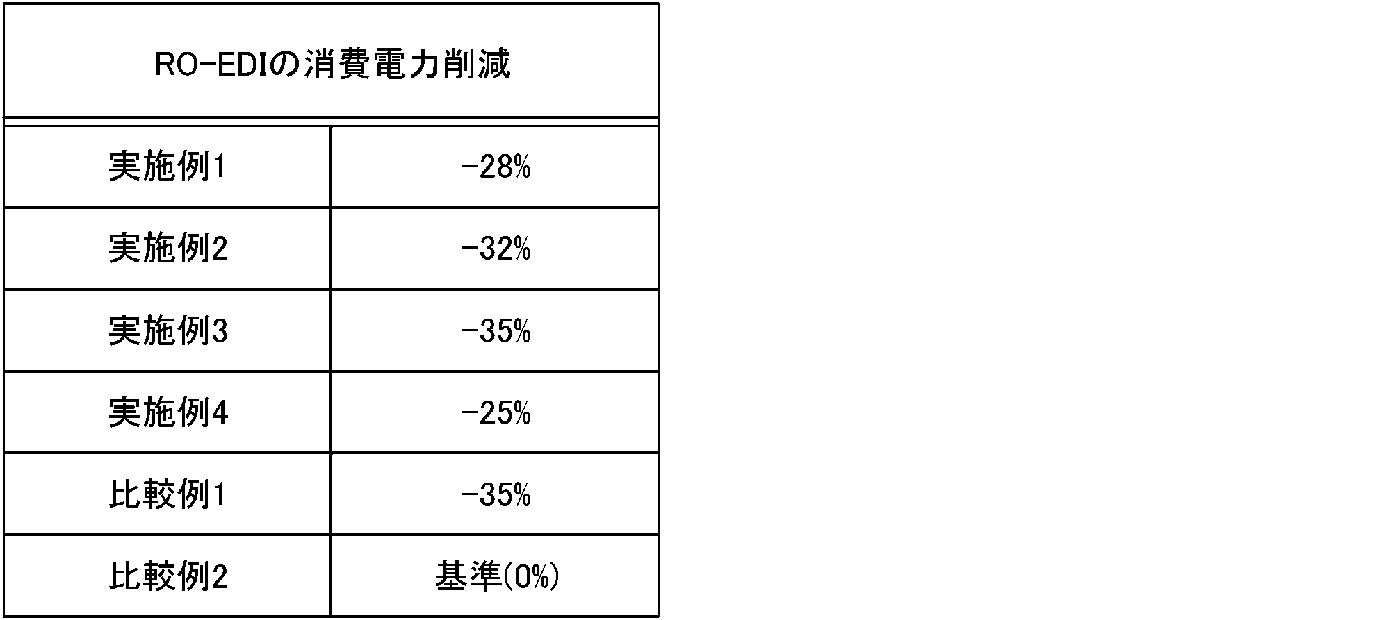
- Table 8 shows the reduction rate of power consumption in each form using the value of power consumption in the second comparison form as a reference (increase/decrease rate is set to 0).
- the RO-EDI operation Power consumption can be reduced by about 25 to 35% based on the value in the second comparison mode.
- High-purity EDI tends to have higher power consumption than general EDI because it removes boron to a higher degree than general EDI.
- the power consumption of EDI equipment for high purity can be reduced by appropriately managing the operation of the RO membrane equipment and keeping the concentration and hardness of silica, which are factors that cause voltage increases in EDI equipment, at low values. , it becomes possible to operate with power consumption reduced to about 1.5 times the power consumption of general EDI equipment.
- the power consumption of the entire system can be reduced due to the effect of reducing power consumption by employing an extremely low pressure RO membrane.
- FIG. 9 is a diagram showing an example of arrangement of pumps in the water treatment system of the present invention.
- FIG. 9 shows three arrangement examples of cases 1 to 3.
- the RO membrane devices 10-1, 10-2 and EDI devices 20-1, 20-2 in each are the same as those in the first embodiment.
- the first pump 40-1 is placed upstream of the RO membrane device 10-1.
- a second pump 40-2 is placed between the RO membrane device 10-2 and the EDI device 20-1.
- a third pump 40-3 is arranged between EDI device 20-1 and EDI device 20-2.
- the first pump 40-1 is placed upstream of the RO membrane device 10-1.
- a second pump 40-2 is arranged between RO membrane device 10-1 and RO membrane device 10-2.
- a third pump 40-3 is arranged between EDI device 20-1 and EDI device 20-2. In case 3, the first pump 40-1 is placed upstream of the RO membrane device 10-1.
- a second pump 40-2 is placed between EDI device 20-1 and EDI device 20-2.
- RO membrane device equipped with an extremely low pressure RO membrane
- the differential pressure at the RO membrane portion is reduced, and two or more components (RO membrane device or EDI device) can be pumped using one pump.
- other components a tank, an ultraviolet irradiation device, a degassing membrane, etc. may be arranged between each component.
- FIG. 10 is a diagram showing pressure values at each point in the form shown in FIG. 3.
- the first pump 40-1 is placed upstream of the RO membrane device 10-1.
- a second pump 40-2 is placed between EDI device 21-1 and EDI device 20-2. That is, one pump 40-1 is used to pass water from the RO membrane device 10-1 to the EDI device 21-1.
- the pump 40-2 increases the pressure of the treated water processed by the EDI device 21-1 and supplies the water to the EDI device 20-2.
- the pressure value at the point between the pump 40-1 and the RO membrane device 10-1 is 1.2 [MPa].
- the pressure value at the point between the RO membrane device 10-2 and the EDI device 21-1 is 0.34 [MPa].
- the pressure value at the point between the EDI device 21-1 and the pump 40-2 is 0.14 [MPa]. Further, the pressure value at the point between the pump 40-2 and the EDI device 20-2 is 0.28 [MPa]. Further, the pressure value at the downstream point of the EDI device 20-2 is 0.10 [MPa]. Since the EDI device had a high flow rate, the differential pressure of the EDI device 21-1 was 0.2 [MPa], and the differential pressure of the EDI device 20-2 was 0.18 [MPa]. However, it was possible to operate without providing a pump before the EDI device 21-1, that is, between the RO membrane device 10-2 and the EDI device 21-1.
- the pump 40-2 placed between the EDI device 21-1 and the EDI device 20-2 is placed between the RO membrane device 10-2 and the EDI device 21-1.
- the differential pressure of the EDI device 20-2 is added to the differential pressure of the EDI device 21-1, and it is necessary to increase the pressure of the water supplied to the EDI device 21-1.
- the pump 40-2 bears the burden of supplying water pressure to both the EDI device 21-1 and the EDI device 20-2, resulting in a large burden.
- EDI devices have lower pressure resistance than RO membrane devices. Therefore, it is preferable to operate the EDI device at 0.5 [MPa] or less.
- the water pressure supplied to the EDI device 21-1 needs to be at least 0.48 [MPa]. . Therefore, considering a certain margin, this is not necessarily preferable.
- FIG. 11 is a diagram showing another example of the structure of the high-purity EDI device used in the present invention. Examples of the structure of the high-purity EDI device used in the present invention are shown in FIGS. 2 and 4, and two other structural examples are shown in FIG.
- the structure shown in the upper part of FIG. 11 has an anode chamber 101 filled with a cation exchange resin, a cathode chamber 102 filled with an anion exchange resin, and a mixed bed filled with a cation exchange resin and an anion exchange resin.
- Concentration chambers 103, 104 and a first demineralization chamber 110 which is a mixed bed filled with a cation exchange resin and an anion exchange resin, are provided.
- Anode chamber 101 and concentration chamber 103 are adjacent to each other with cation exchange membrane 201 in between.
- Concentration chamber 103 and first demineralization chamber 110 are adjacent to each other with an anion exchange membrane 202 in between.
- the first demineralization chamber 110 and the concentration chamber 104 are adjacent to each other with a cation exchange membrane 201 in between.
- Concentration chamber 104 and cathode chamber 102 are adjacent to each other with an anion exchange membrane 202 in between.
- an anode chamber 101 filled with a cation exchange resin, a cathode chamber 102 filled with an anion exchange resin, concentration chambers 111 and 112 filled with a cation exchange resin, and a cation exchange resin are provided.
- a first demineralization chamber 110 which is a mixed bed filled with an exchange resin and an anion exchange resin, is provided.
- Anode chamber 101 and concentration chamber 111 are adjacent to each other with cation exchange membrane 201 in between.
- the concentration chamber 111 and the first demineralization chamber 110 are adjacent to each other with an anion exchange membrane 202 in between.
- the first demineralization chamber 110 and the concentration chamber 112 are adjacent to each other with a cation exchange membrane 201 in between.
- Concentration chamber 112 and cathode chamber 102 are adjacent to each other with an anion exchange membrane 202 in between.
- the lowest layer of the desalination chamber is filled with at least an anion exchange resin
- the concentration chamber adjacent to the desalination chamber via the cation exchange membrane that partitions the desalination chamber is filled with at least an anion exchange resin. Filled with cation exchange resin.
- the demineralization chamber may be filled with only the anion exchange resin.
- a plurality of basic structures as described in Examples 1 and 2 may be stacked. This increases the amount of water that can be treated.
- the anode chamber 101 may also serve as the concentration chambers 103, 111 without providing the cation exchange membrane 201 located between the anode chamber 101 and the concentration chambers 103, 111.
- the anion exchange membrane 202 located between the cathode chamber 102 and the concentration chambers 104, 112 may not be provided, and the cathode chamber 102 may also serve as the concentration chambers 104, 112. Note that the conditions for high flow rate of the EDI stack in the configuration shown in FIG. It is to be.
- the EDI device can perform continuous electrical regeneration by applying direct current. Therefore, compared to other ion exchange resin devices, EDI equipment has a high flow rate (SV) per resin volume, and is generally operated at a flow rate of about 150 to 250 h -1 .
- the water flow differential pressure is about 0.09 to 0.15 [MPa].
- the pressure loss of the RO membrane device is reduced, and the supply (pressure boost) pump and It becomes unnecessary to install a tank. Furthermore, since there is no need to add chemicals to adjust the pH of the target water, it is possible to reduce the cost of chemicals, equipment for adding chemicals, and management costs. Further, the RO membrane device is operated such that the silica concentration and hardness in the permeated water of the RO membrane, which causes an increase in the electrical resistance of the EDI device, are below a certain concentration. This makes it possible to increase the current while suppressing the voltage rise of the EDI device, and it becomes possible to obtain treated water of higher purity.
- the present invention can provide a water treatment system with low energy consumption and low management costs.
- the boron removal rate can be improved without imposing a large load.
Landscapes
- Chemical & Material Sciences (AREA)
- Engineering & Computer Science (AREA)
- Water Supply & Treatment (AREA)
- Chemical Kinetics & Catalysis (AREA)
- Life Sciences & Earth Sciences (AREA)
- Environmental & Geological Engineering (AREA)
- Hydrology & Water Resources (AREA)
- Organic Chemistry (AREA)
- Health & Medical Sciences (AREA)
- Urology & Nephrology (AREA)
- Analytical Chemistry (AREA)
- Molecular Biology (AREA)
- Electrochemistry (AREA)
- General Chemical & Material Sciences (AREA)
- Nanotechnology (AREA)
- Separation Using Semi-Permeable Membranes (AREA)
Abstract
Description
被処理水に含まれる少なくともホウ素を除去する水処理システムであって、
極超低圧RO膜を含むRO膜装置と、
前記RO膜装置の後段に配置され、脱塩室の最下流層に少なくともアニオン交換樹脂が充填され、前記脱塩室を区画するカチオン交換膜を介して隣接する濃縮室に少なくともカチオン交換樹脂が充填されている高純度向けEDIスタックを含むEDI装置とを有し、
前記RO膜装置が2段RO膜装置であり、1段目と2段目との少なくとも一方に前記極超低圧RO膜が配置されている。
被処理水に含まれる少なくともホウ素を除去する水処理方法であって、
高純度向けEDIスタックを含むEDI装置へ供給される被処理水のホウ素濃度が20~100[μg/L]、シリカ濃度が50[μg/L]以下、硬度が0.05[mgCaCO3/L]以下となるように、前記EDI装置の前段に設けられた、極超低圧型RO膜装置を含むRO膜装置を運転する。

(実施例1)
(実施例2)

(実施例3)

(実施例4)

(比較例1)

(比較例2)
Claims (8)
- 被処理水に含まれる少なくともホウ素を除去する水処理システムであって、
極超低圧RO膜を含むRO膜装置と、
前記RO膜装置の後段に配置され、脱塩室の最下流層に少なくともアニオン交換樹脂が充填され、前記脱塩室を区画するカチオン交換膜を介して隣接する濃縮室に少なくともカチオン交換樹脂が充填されている高純度向けEDIスタックを含むEDI装置とを有し、
前記RO膜装置が2段RO膜装置であり、1段目と2段目との少なくとも一方に前記極超低圧RO膜が配置されている水処理システム。 - 請求項1に記載の水処理システムにおいて、
前記EDI装置が2段EDI装置であり、1段目と2段目との少なくとも一方に前記高純度向けEDIスタックが配置されている水処理システム。 - 請求項2に記載の水処理システムにおいて、
前記被処理水を前記RO膜装置と前記EDI装置とへ通液するためのポンプを複数有し、
前記複数のポンプのうち少なくとも1つのポンプは、前記RO膜装置と前記EDI装置とのうち互いに直列配置された2つ以上の装置へ前記被処理水を供給するように配置されている水処理システム。 - 請求項1から3のいずれか1項に記載の水処理システムにおいて、
前記極超低圧RO膜は、原液に含まれるNaClの濃度が500~2000[mg/L]であり、pHが6~8であり、水温が25℃であり、透過水回収率が10~25%である条件下で測定された塩除去率が99.4%未満であり、供給圧力1[MPa]・膜面積1[m2]あたりの透過水量(単位圧力・単位面積あたりの透過水流量)が、1.3[(m3/d)/(m2・MPa)]以上の膜である水処理システム。 - 被処理水に含まれる少なくともホウ素を除去する水処理方法であって、
高純度向けEDIスタックを含むEDI装置へ供給される被処理水のホウ素濃度が20~100[μg/L]、シリカ濃度が50[μg/L]以下、硬度が0.05[mgCaCO3/L]以下となるように、前記EDI装置の前段に設けられた、極超低圧型RO膜装置を含むRO膜装置を運転する水処理方法。 - 請求項5に記載の水処理方法において、
前記高純度向けEDIスタックを含むEDI装置の脱塩室に、該脱塩室に充填されているイオン交換樹脂体積当たりの流量が350~450[h-1]となるように通水する水処理方法。 - 請求項6に記載の水処理方法において、
前記脱塩室の通水差圧が0.18~0.3[MPa]となるように通水する水処理方法。 - 請求項5から7のいずれか1項に記載の水処理方法において、
前記高純度向けEDIスタックを含むEDI装置に、電流密度が0.8~1.2[A/dm2]となる電流を流す水処理方法。
Priority Applications (4)
| Application Number | Priority Date | Filing Date | Title |
|---|---|---|---|
| JP2024544020A JPWO2024048115A1 (ja) | 2022-08-31 | 2023-07-20 | |
| CN202380058577.5A CN119585212A (zh) | 2022-08-31 | 2023-07-20 | 水处理系统以及水处理方法 |
| KR1020257009706A KR20250048136A (ko) | 2022-08-31 | 2023-07-20 | 수처리 시스템 및 수처리 방법 |
| US18/994,169 US20250346514A1 (en) | 2022-08-31 | 2023-07-20 | Water treatment system and water treatment method |
Applications Claiming Priority (2)
| Application Number | Priority Date | Filing Date | Title |
|---|---|---|---|
| JP2022138237 | 2022-08-31 | ||
| JP2022-138237 | 2022-08-31 |
Publications (1)
| Publication Number | Publication Date |
|---|---|
| WO2024048115A1 true WO2024048115A1 (ja) | 2024-03-07 |
Family
ID=90099561
Family Applications (1)
| Application Number | Title | Priority Date | Filing Date |
|---|---|---|---|
| PCT/JP2023/026652 Ceased WO2024048115A1 (ja) | 2022-08-31 | 2023-07-20 | 水処理システムおよび水処理方法 |
Country Status (6)
| Country | Link |
|---|---|
| US (1) | US20250346514A1 (ja) |
| JP (1) | JPWO2024048115A1 (ja) |
| KR (1) | KR20250048136A (ja) |
| CN (1) | CN119585212A (ja) |
| TW (1) | TW202413281A (ja) |
| WO (1) | WO2024048115A1 (ja) |
Cited By (1)
| Publication number | Priority date | Publication date | Assignee | Title |
|---|---|---|---|---|
| WO2025004642A1 (ja) * | 2023-06-29 | 2025-01-02 | 栗田工業株式会社 | 純水製造システムおよび純水製造方法 |
Citations (8)
| Publication number | Priority date | Publication date | Assignee | Title |
|---|---|---|---|---|
| JP2004283710A (ja) * | 2003-03-20 | 2004-10-14 | Kurita Water Ind Ltd | 純水製造装置 |
| JP2016129863A (ja) * | 2015-01-13 | 2016-07-21 | オルガノ株式会社 | 電気式脱イオン水製造装置 |
| JP2018001106A (ja) * | 2016-07-04 | 2018-01-11 | 栗田工業株式会社 | 電気脱イオン装置及びその運転方法 |
| JP2018051453A (ja) * | 2016-09-27 | 2018-04-05 | オルガノ株式会社 | 電気式脱イオン水製造装置およびその運転方法 |
| JP2019135054A (ja) * | 2019-05-22 | 2019-08-15 | オルガノ株式会社 | 水処理装置および水処理方法 |
| WO2020003831A1 (ja) * | 2018-06-27 | 2020-01-02 | 野村マイクロ・サイエンス株式会社 | 電気式脱イオン装置、超純水製造システムおよび超純水製造方法 |
| JP2021181069A (ja) * | 2020-05-20 | 2021-11-25 | オルガノ株式会社 | ホウ素除去装置及びホウ素除去方法、並びに、純水製造装置及び純水の製造方法 |
| JP2022060806A (ja) * | 2020-10-05 | 2022-04-15 | オルガノ株式会社 | 純水製造システムおよび純水製造方法 |
Family Cites Families (4)
| Publication number | Priority date | Publication date | Assignee | Title |
|---|---|---|---|---|
| JP4045658B2 (ja) | 1998-08-06 | 2008-02-13 | 栗田工業株式会社 | 純水製造方法 |
| CN100453153C (zh) * | 2006-08-17 | 2009-01-21 | 贵阳时代汇通膜科技有限公司 | 一种极低压复合反渗透膜的生产方法 |
| JP5733351B2 (ja) | 2013-07-22 | 2015-06-10 | 栗田工業株式会社 | ホウ素含有水の処理方法及び装置 |
| JP7200014B2 (ja) * | 2019-03-13 | 2023-01-06 | オルガノ株式会社 | 純水製造装置および純水の製造方法 |
-
2023
- 2023-07-20 WO PCT/JP2023/026652 patent/WO2024048115A1/ja not_active Ceased
- 2023-07-20 JP JP2024544020A patent/JPWO2024048115A1/ja active Pending
- 2023-07-20 KR KR1020257009706A patent/KR20250048136A/ko active Pending
- 2023-07-20 CN CN202380058577.5A patent/CN119585212A/zh active Pending
- 2023-07-20 US US18/994,169 patent/US20250346514A1/en active Pending
- 2023-08-22 TW TW112131455A patent/TW202413281A/zh unknown
Patent Citations (8)
| Publication number | Priority date | Publication date | Assignee | Title |
|---|---|---|---|---|
| JP2004283710A (ja) * | 2003-03-20 | 2004-10-14 | Kurita Water Ind Ltd | 純水製造装置 |
| JP2016129863A (ja) * | 2015-01-13 | 2016-07-21 | オルガノ株式会社 | 電気式脱イオン水製造装置 |
| JP2018001106A (ja) * | 2016-07-04 | 2018-01-11 | 栗田工業株式会社 | 電気脱イオン装置及びその運転方法 |
| JP2018051453A (ja) * | 2016-09-27 | 2018-04-05 | オルガノ株式会社 | 電気式脱イオン水製造装置およびその運転方法 |
| WO2020003831A1 (ja) * | 2018-06-27 | 2020-01-02 | 野村マイクロ・サイエンス株式会社 | 電気式脱イオン装置、超純水製造システムおよび超純水製造方法 |
| JP2019135054A (ja) * | 2019-05-22 | 2019-08-15 | オルガノ株式会社 | 水処理装置および水処理方法 |
| JP2021181069A (ja) * | 2020-05-20 | 2021-11-25 | オルガノ株式会社 | ホウ素除去装置及びホウ素除去方法、並びに、純水製造装置及び純水の製造方法 |
| JP2022060806A (ja) * | 2020-10-05 | 2022-04-15 | オルガノ株式会社 | 純水製造システムおよび純水製造方法 |
Cited By (4)
| Publication number | Priority date | Publication date | Assignee | Title |
|---|---|---|---|---|
| WO2025004642A1 (ja) * | 2023-06-29 | 2025-01-02 | 栗田工業株式会社 | 純水製造システムおよび純水製造方法 |
| JP2025006504A (ja) * | 2023-06-29 | 2025-01-17 | 栗田工業株式会社 | 純水製造システムおよび純水製造方法 |
| JP2025010165A (ja) * | 2023-06-29 | 2025-01-20 | 栗田工業株式会社 | 純水製造システムおよび純水製造方法 |
| JP7639856B2 (ja) | 2023-06-29 | 2025-03-05 | 栗田工業株式会社 | 純水製造システムおよび純水製造方法 |
Also Published As
| Publication number | Publication date |
|---|---|
| US20250346514A1 (en) | 2025-11-13 |
| JPWO2024048115A1 (ja) | 2024-03-07 |
| TW202413281A (zh) | 2024-04-01 |
| CN119585212A (zh) | 2025-03-07 |
| KR20250048136A (ko) | 2025-04-07 |
Similar Documents
| Publication | Publication Date | Title |
|---|---|---|
| US8628653B2 (en) | Electrodeionization apparatus | |
| US12570546B2 (en) | Control method for ultrapure water producing apparatus | |
| JP6799657B1 (ja) | 水処理システム及び超純水製造システム並びに水処理方法 | |
| JP3826690B2 (ja) | 電気脱イオン装置及び純水製造装置 | |
| KR101138382B1 (ko) | 전기식 탈이온수 제조장치의 운전방법, 전기식 탈이온수제조시스템 및 전기식 탈이온수 제조장치 | |
| US12172917B2 (en) | Pure-water production device and pure-water production method | |
| TWI701218B (zh) | 水處理裝置及水處理方法 | |
| JP2009226315A (ja) | 電気式脱イオン水製造装置及び脱イオン水の製造方法 | |
| CN112424128A (zh) | 纯水制造系统及纯水制造方法 | |
| JP4250922B2 (ja) | 超純水製造システム | |
| JP4993136B2 (ja) | 純水製造装置及び純水製造方法 | |
| WO2024048115A1 (ja) | 水処理システムおよび水処理方法 | |
| JP4856617B2 (ja) | 電気式脱イオン水製造装置及びその運転方法 | |
| US12606467B2 (en) | Water treatment method and water treatment apparatus | |
| JP2003266097A (ja) | 超純水製造装置 | |
| EP4692000A1 (en) | Method for operating electric deionizer | |
| JP4505965B2 (ja) | 純水の製造方法 | |
| TWI887482B (zh) | 純水製造系統及純水製造方法 | |
| KR20250095612A (ko) | 순수 제조 방법, 순수 제조 장치 및 초순수 제조 시스템 | |
| JP6807250B2 (ja) | 水処理装置 | |
| JP2022138431A (ja) | 水処理方法及び水処理装置 | |
| JP3674475B2 (ja) | 純水の製造方法 | |
| JP4453972B2 (ja) | 電気脱イオン装置及び電気脱イオン装置の運転方法 | |
| TWI916506B (zh) | 水處理方法及水處理裝置 | |
| JP4915843B2 (ja) | 電気軟化装置、軟化装置及び軟水製造方法 |
Legal Events
| Date | Code | Title | Description |
|---|---|---|---|
| 121 | Ep: the epo has been informed by wipo that ep was designated in this application |
Ref document number: 23859884 Country of ref document: EP Kind code of ref document: A1 |
|
| WWE | Wipo information: entry into national phase |
Ref document number: 2024544020 Country of ref document: JP |
|
| WWE | Wipo information: entry into national phase |
Ref document number: 18994169 Country of ref document: US |
|
| WWE | Wipo information: entry into national phase |
Ref document number: 202380058577.5 Country of ref document: CN |
|
| WWP | Wipo information: published in national office |
Ref document number: 202380058577.5 Country of ref document: CN |
|
| ENP | Entry into the national phase |
Ref document number: 20257009706 Country of ref document: KR Kind code of ref document: A |
|
| WWE | Wipo information: entry into national phase |
Ref document number: 1020257009706 Country of ref document: KR |
|
| NENP | Non-entry into the national phase |
Ref country code: DE |
|
| WWP | Wipo information: published in national office |
Ref document number: 1020257009706 Country of ref document: KR |
|
| 122 | Ep: pct application non-entry in european phase |
Ref document number: 23859884 Country of ref document: EP Kind code of ref document: A1 |
|
| WWP | Wipo information: published in national office |
Ref document number: 18994169 Country of ref document: US |