WO2024034404A1 - アクチュエータドライバおよびこれを用いたカメラモジュール、電子機器、可動部の位置検出方法 - Google Patents
アクチュエータドライバおよびこれを用いたカメラモジュール、電子機器、可動部の位置検出方法 Download PDFInfo
- Publication number
- WO2024034404A1 WO2024034404A1 PCT/JP2023/027429 JP2023027429W WO2024034404A1 WO 2024034404 A1 WO2024034404 A1 WO 2024034404A1 JP 2023027429 W JP2023027429 W JP 2023027429W WO 2024034404 A1 WO2024034404 A1 WO 2024034404A1
- Authority
- WO
- WIPO (PCT)
- Prior art keywords
- value
- digital signal
- position detection
- signal
- actuator driver
- Prior art date
- Legal status (The legal status is an assumption and is not a legal conclusion. Google has not performed a legal analysis and makes no representation as to the accuracy of the status listed.)
- Ceased
Links
Images



Classifications
-
- G—PHYSICS
- G02—OPTICS
- G02B—OPTICAL ELEMENTS, SYSTEMS OR APPARATUS
- G02B7/00—Mountings, adjusting means, or light-tight connections, for optical elements
- G02B7/02—Mountings, adjusting means, or light-tight connections, for optical elements for lenses
- G02B7/04—Mountings, adjusting means, or light-tight connections, for optical elements for lenses with mechanism for focusing or varying magnification
-
- G—PHYSICS
- G02—OPTICS
- G02B—OPTICAL ELEMENTS, SYSTEMS OR APPARATUS
- G02B7/00—Mountings, adjusting means, or light-tight connections, for optical elements
- G02B7/02—Mountings, adjusting means, or light-tight connections, for optical elements for lenses
- G02B7/04—Mountings, adjusting means, or light-tight connections, for optical elements for lenses with mechanism for focusing or varying magnification
- G02B7/08—Mountings, adjusting means, or light-tight connections, for optical elements for lenses with mechanism for focusing or varying magnification adapted to co-operate with a remote control mechanism
-
- G—PHYSICS
- G03—PHOTOGRAPHY; CINEMATOGRAPHY; ANALOGOUS TECHNIQUES USING WAVES OTHER THAN OPTICAL WAVES; ELECTROGRAPHY; HOLOGRAPHY
- G03B—APPARATUS OR ARRANGEMENTS FOR TAKING PHOTOGRAPHS OR FOR PROJECTING OR VIEWING THEM; APPARATUS OR ARRANGEMENTS EMPLOYING ANALOGOUS TECHNIQUES USING WAVES OTHER THAN OPTICAL WAVES; ACCESSORIES THEREFOR
- G03B5/00—Adjustment of optical system relative to image or object surface other than for focusing
-
- H—ELECTRICITY
- H02—GENERATION; CONVERSION OR DISTRIBUTION OF ELECTRIC POWER
- H02P—CONTROL OR REGULATION OF ELECTRIC MOTORS, ELECTRIC GENERATORS OR DYNAMO-ELECTRIC CONVERTERS; CONTROLLING TRANSFORMERS, REACTORS OR CHOKE COILS
- H02P25/00—Arrangements or methods for the control of AC motors characterised by the kind of AC motor or by structural details
- H02P25/02—Arrangements or methods for the control of AC motors characterised by the kind of AC motor or by structural details characterised by the kind of motor
- H02P25/032—Reciprocating, oscillating or vibrating motors
- H02P25/034—Voice coil motors
-
- H—ELECTRICITY
- H04—ELECTRIC COMMUNICATION TECHNIQUE
- H04N—PICTORIAL COMMUNICATION, e.g. TELEVISION
- H04N23/00—Cameras or camera modules comprising electronic image sensors; Control thereof
- H04N23/50—Constructional details
- H04N23/54—Mounting of pick-up tubes, electronic image sensors, deviation or focusing coils
-
- H—ELECTRICITY
- H04—ELECTRIC COMMUNICATION TECHNIQUE
- H04N—PICTORIAL COMMUNICATION, e.g. TELEVISION
- H04N23/00—Cameras or camera modules comprising electronic image sensors; Control thereof
- H04N23/60—Control of cameras or camera modules
- H04N23/68—Control of cameras or camera modules for stable pick-up of the scene, e.g. compensating for camera body vibrations
Definitions
- the present disclosure relates to an actuator driver and a camera module using the same.
- a camera module with optical image stabilization includes an image sensor, a lens movable in an XY plane parallel to the imaging surface of the image sensor (referred to as an image stabilization lens), an actuator that positions the lens, and an actuator driver that controls the actuator. Equipped with.
- a shake detection means such as a gyro sensor
- the actuator driver drives the actuator to shift the lens so that the shake is canceled out.
- the output of the Hall element (Hall signal) is expected to change monotonically with respect to the position of the movable part, and more ideally, it is expected to change linearly.
- the Hall signal has a maximum point and a minimum point with respect to the position. For this reason, in a module in which the movable part has a wide movable range, one Hall element cannot cover the entire movable range.
- the present disclosure has been made in such a situation, and one of its exemplary purposes is to provide an actuator driver and a camera module that can detect the position of a movable part in combination with an actuator having a long stroke length.
- An aspect of the present disclosure relates to an actuator driver that drives an actuator that positions a movable part.
- the actuator driver receives n Hall signals from a plurality of n Hall elements (n ⁇ 2), converts the n Hall signals into n digital signals, and operates based on the n digital signals.
- a position detection unit that generates a feedback signal indicating the position of the motor
- a servo controller that generates a control signal so that the feedback signal approaches a target value
- a drive unit that applies a drive signal according to the control signal to the voice coil motor.
- the position detection section folds back each of the n digital signals at a local maximum value and a local minimum value, synthesizes the folded digital signals, and generates a feedback signal.
- Another aspect of the present disclosure relates to a method for detecting the position of a movable part positioned by an actuator.
- This method includes the steps of arranging a plurality of n Hall elements (n ⁇ 2) along the stroke direction of the movable part, and converting the n Hall signals generated by the n Hall elements into n digital signals.
- the method includes a step of converting, and a step of folding back each of the n digital signals at a maximum value and a minimum value, and synthesizing the folded digital signals to generate a position detection signal.
- the position of the movable part can be detected in combination with an actuator having a long stroke length.
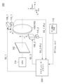
- FIG. 1 is a block diagram of a camera module equipped with an image stabilization function.
- FIG. 2 is a block diagram of the actuator driver.
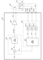
- FIG. 3 is a block diagram of the actuator driver according to the embodiment.
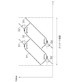
- FIG. 4 is a diagram illustrating the loopback process of the position detection unit in FIG. 3.
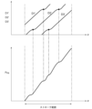
- FIG. 5 is a diagram illustrating the compositing process of the position detection section of FIG. 3.
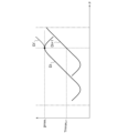
- FIG. 6 is a diagram illustrating loopback processing regarding local maximum values performed by the arithmetic processing unit.
- FIG. 7 is a diagram illustrating loopback processing regarding local minimum values performed by the arithmetic processing unit.
- FIG. 8 is a block diagram showing an example of the configuration of the arithmetic processing section.
- FIG. 9 is a block diagram of a folding processing section according to a modified example.
- An actuator driver drives an actuator that positions a movable part.
- the actuator driver receives n Hall signals from a plurality of n Hall elements (n ⁇ 2), converts the n Hall signals into n digital signals, and operates based on the n digital signals.
- a position detection unit that generates a feedback signal indicating the position of the motor
- a servo controller that generates a control signal so that the feedback signal approaches a target value
- a drive unit that applies a drive signal according to the control signal to the voice coil motor.
- the position detection section folds back each of the n digital signals at a local maximum value and a local minimum value, synthesizes the folded digital signals, and generates a feedback signal.
- the position of the movable element can be detected over a long stroke length by arranging a plurality of Hall elements side by side in the stroke direction of the movable part and synthesizing the plurality of Hall signals.
- the Hall signals have local maximum values and local minimum values, if multiple Hall signals are simply added and synthesized, there will be a region where the slope of the combined signal is very small, resulting in a decrease in sensitivity. becomes.
- by folding back the digital signal corresponding to the Hall signal at its maximum value and minimum value it is possible to prevent the slope of the synthesized digital signal from becoming too small, and it is possible to increase the position detection sensitivity.
- the position detection unit detects the local maximum value pmax i of the i-th (1 ⁇ i ⁇ n-1) digital signal and the (i+1)-th maximum value pmax i when the i-th digital signal takes the local maximum value pmax i.
- a maximum threshold value THmax i+1 which is the value p i+1 of the digital signal, is held, and when the value p i+1 of the (i+1)th digital signal is larger than the maximum threshold value THmax i+1 , the i-th digital signal
- the position detection unit detects the minimum value pmin j of the jth ((2 ⁇ j ⁇ n) digital signal and the (j-1)th minimum value pmin j when the jth digital signal takes the minimum value pmin j.
- the value p j-1 of the (j-1)th digital signal is the minimum threshold THmin j-1 , which is the value p j -1 of the digital signal.
- the value p j of the j-th digital signal may be converted to 2 ⁇ pmin j ⁇ p j .
- the servo controller may include an error detector that generates an error between the target value and the feedback signal, and a proportional-integral controller that receives the error.
- the actuator driver may be monolithically integrated on one semiconductor substrate.
- “Integration” includes cases where all of the circuit components are formed on a semiconductor substrate, cases where the main components of the circuit are integrated, and some of the components are integrated to adjust the circuit constants.
- a resistor, a capacitor, etc. may be provided outside the semiconductor substrate.
- a camera module includes an image sensor, an image stabilization mechanism provided on an incident optical path to the image sensor, an actuator that positions a movable part of the image stabilization mechanism, and an actuator driver. Good too.
- a camera module includes an image sensor, an image stabilization lens provided on an incident optical path to the image sensor, an actuator that positions a movable part including the image stabilization lens, and any of the above-mentioned actuators.
- a driver is provided on an image sensor, an image stabilization lens provided on an incident optical path to the image sensor, an actuator that positions a movable part including the image stabilization lens, and any of the above-mentioned actuators.
- a state in which member A is connected to member B refers to not only a case where member A and member B are physically directly connected, but also a state in which member A and member B are electrically connected. This also includes cases in which they are indirectly connected via other members that do not substantially affect the connection state or impair the functions and effects achieved by their combination.
- a state in which member C is provided between member A and member B refers to the case where member A and member C or member B and member C are directly connected, This also includes cases in which they are indirectly connected via other members that do not substantially affect the connection state or impair the functions and effects achieved by their combination.
- FIG. 1 is a block diagram of a camera module equipped with an image stabilization function.
- the camera module 100 includes an image sensor 102, an image stabilization lens 104, a first actuator 106_1, a second actuator 106_2, an actuator driver 200, position detection elements 110_1, 110_2, a shake detection means 112, and a CPU (Central Processing Unit) 114. .
- the camera module 100 also includes an autofocus lens, an actuator, etc., but these are omitted in FIG.
- the optical axis direction of the camera shake correction lens 104 is assumed to be the Z-axis. Further, when the camera module 100 is in the attitude shown in FIG. 1, the horizontal direction is assumed to be the X axis, and the vertical direction is assumed to be the Y axis.
- the X axis is also referred to as the first axis, and the Y axis is also referred to as the second axis.
- the camera shake correction lens 104 is placed on the optical path of light incident on the image sensor 102.
- the image sensor 102 is a CMOS sensor or CCD, and captures an image transmitted through the camera shake correction lens 104.
- the camera shake correction lens 104 is supported so as to be movable in the X direction and the Y direction in a plane parallel to the imaging surface of the image sensor 102 (XY plane).
- the first actuator 106_1 positions the movable part 105 including the camera shake correction lens 104 in the first axis (X-axis) direction
- the second actuator 106_2 positions the movable part 105 in the second axis (Y-axis) direction.
- the first actuator 106_1 and the second actuator 106_2 are linear actuators, and for example, voice coil motors are used.
- the movable portion 105 including the camera shake correction lens 104 has a movable range mechanically restricted in each of the first axis direction and the second axis direction. The end of the movable range is called the mechanical end. Mechanical ends exist in the positive direction and negative direction in the first axis direction, and mechanical ends exist in the positive direction and the negative direction in the second axis direction as well.
- the shake detection means 112 detects shake of the camera module 100 and generates a shake detection signal S1 indicating the shake.
- the shake detection means 112 is, for example, a gyro sensor, and detects the angular velocity ⁇ X around the X axis, the angular velocity ⁇ Y around the Y axis, and the angular velocity ⁇ Z around the Z axis of the camera module 100.
- rotation (shake) around the Y-axis can be corrected
- the shake detection signal S1 includes angular velocities ⁇ X and ⁇ Y of at least two axes.
- the actuator driver 200 Based on the shake detection signal S1 detected by the shake detection means 112, the actuator driver 200 generates a target code (position command) indicating a target value of the displacement of the camera shake correction lens 104 so that the shake is canceled out.
- the actuator driver 200 generates drive signals S2_1 and S2_2 for the first actuator 106_1 and the second actuator 106_2, respectively, based on internally generated target codes.
- the position detection elements 110_1 and 110_2 respectively generate position detection signals S3_1 and S3_2 indicating the position (displacement amount) PX in the first axis direction and the position (displacement amount) PY in the second axis direction of the camera shake correction lens 104. do.
- a Hall sensor or the like can be used as the position detection element 110.
- the actuator driver 200 drives the first actuator 106_1 and the second actuator 106_2 so that camera shake is corrected. Specifically, in the first mode, the actuator driver 200 operates so that the position PX of the camera shake correction lens 104 indicated by the first position detection signal S3_1 matches the target position PX (REF) indicated by the target code.
- the drive signal S2_1 is feedback-controlled.
- the actuator driver 200 performs feedback control on the drive signal S2_2 so that the position P Y of the camera shake correction lens 104 indicated by the second position detection signal S3_2 matches the target position P Y (REF) indicated by the target code. do.
- the above is the overall configuration of the camera module 100. Next, the actuator driver 200 will be explained.
- FIG. 2 is a block diagram of the actuator driver 200.
- the actuator driver 200 includes a control section 210, a first drive section 220_1, and a second drive section 220_2.
- the gyro sensor 112A is the shake detection means 112 in FIG. 1 and detects the angular velocity of the camera module 100.
- the control unit 210 includes a position command generation unit 212, a first servo controller 230_1, a second servo controller 230_2, a first position detection unit 240_1, and a second position detection unit 240_2.
- the position command generation unit 212 receives the shake detection signal S1 generated by the gyro sensor 112A, and generates a position indicating the position of the camera shake correction lens 104 that can offset the shake for each of the X-axis and Y-axis. Generate commands X REF and Y REF .
- the position command generation unit 212 generates the position command X REF by integrating the angular velocity ⁇ X around the X-axis and multiplying it by a predetermined gain.
- the position command generation unit 212 generates the position command Y REF by integrating the angular velocity ⁇ Y around the Y-axis and multiplying it by a predetermined gain.
- the position detection signal S3_1 generated by the position detection element 110_1 is input to the first position detection section 240_1.
- the first position detection unit 240_1 generates a feedback signal XFB indicating the position of the movable element of the actuator 106_1 based on the position detection signal S3_1.
- the position detection signal S3_2 generated by the position detection element 110_2 is input to the second position detection section 240_2.
- the second position detection unit 240_2 generates a feedback signal YFB indicating the position of the movable element of the actuator 106_2 based on the position detection signal S3_2.
- Feedback signals X FB and Y FB indicate the positions of the movable portion 105 in the X direction and Y direction (X coordinate, Y coordinate), respectively.
- the first servo controller 230_1 generates the control signal S4_1 so that the error between the feedback signal X FB and the position command X REF approaches zero.
- the first drive unit 220_1 generates a drive signal S2_1 according to the control signal S4_1.
- the control signal S4_1 is, for example, a current command, and the first drive unit 220_1 supplies the first actuator 106_1 with a drive current having an amount of current according to the control signal S4_1.
- the control signal S4_1 is a voltage command, and the first drive unit 220_1 supplies the first actuator 106_1 with a drive voltage at a voltage level corresponding to the control signal S4_1.
- the second servo controller 230_2 receives the position detection signal S3_2 generated by the position detection element 110_2 as a feedback signal YFB indicating the Y coordinate of the movable part 105.
- the second servo controller 230_2 generates the control signal S4_2 so that the error between the feedback signal Y FB and the position command Y REF approaches zero.
- the second drive unit 220_2 generates a drive signal S2_2 according to the control signal S4_2.
- the configuration of the actuator driver 200 (220_1, 230_1, 240_1) corresponding to the actuator 106_1 is the same as the configuration (220_2, 230_2, 240_2) of the actuator driver 200 corresponding to the actuator 106_2.
- FIG. 3 is a block diagram of the actuator driver 200 according to the embodiment.
- the servo controller 230 in FIG. 3 corresponds to the first servo controller 230_1 or the second servo controller 230_2 in FIG. 2.
- P in FIG. 3 is X or Y in FIG.
- the driving unit 220 in FIG. 3 corresponds to the first driving unit 220_1 or the second driving unit 220_2 in FIG. 2.
- the position detection unit 240 in FIG. 3 corresponds to the first position detection unit 240_1 or the second position detection unit 240_2 in FIG. 2.
- the servo controller 230 includes an error detector 232 and a compensator 234.
- the error detector 232 generates an error err between the position command P REF and the feedback signal P FB indicating the position of the movable part 105 .
- Error detector 232 can be configured with a subtracter.
- the compensator 234 generates a control signal ctrl according to the error err.
- Compensator 234 is also referred to as a servo filter.
- the compensator 234 is, for example, a PI (proportional/integral) controller, and adds the value obtained by multiplying the error err by a proportional gain kp and the value obtained by multiplying the integral value of the error err by an integral gain ki, and generates a control signal.
- ctrl may be generated.
- Compensator 234 may be a PID (proportional-integral-derivative controller).
- the drive unit 220 applies a drive signal S2 according to the control signal S4 (ctrl) to the voice coil of the actuator 106.
- the n Hall elements H1 to Hn are arranged along the stroke direction of the actuator 106.
- Each Hall element Hi (1 ⁇ i ⁇ n) generates a Hall signal HSi according to the position of the movable part of the actuator 106.
- the plurality of Hall signals SH1 to SH3 are input to pins ADC1 to ADC3 of the actuator driver 200.
- the position detection unit 240 receives n Hall signals HS1 to HS3 and converts the n Hall signals into n digital signals D1 to Dn. Then, based on the digital signals D1 to Dn, a feedback signal PFB indicating the position of the movable part is generated.
- the position detection unit 240 includes, for example, n A/D converters 242_1 to 242_n and an arithmetic processing unit 250.
- the i-th A/D converter 242_i converts the corresponding Hall signal HSi into a digital signal Di. Note that one A/D converter 242 may time-divisionally convert a plurality of Hall signals HS1 to HSn into digital signals D1 to Dn.
- the position detection unit 240 may further include a Hall amplifier that amplifies the Hall signal HS.
- the arithmetic processing unit 250 generates a feedback signal PFB based on the n digital signals D1 to Dn.
- the arithmetic processing unit 250 returns each of the n digital signals D1 to Dn at a maximum value and a minimum value. Then, the folded digital signals D1' to Dn' are combined to generate a feedback signal PFB .
- FIG. 4 is a diagram illustrating the loopback process of the position detection unit 240 in FIG. 3.
- the horizontal axis represents the position P of the movable part of the actuator 106, and the vertical axis represents the value of the digital signal.
- FIG. 4 shows the digital signals D1 to D3 and the folded digital signals D1' to D3'.
- a portion of the digital signal D1 is folded back using its maximum value pmax1 as a reference.
- a portion of the digital signal D2 is folded back using the minimum value pmin 2 as a reference, and another portion is folded back using the maximum value pmax 2 as a reference.
- a portion of the digital signal D3 is folded back based on its minimum value pmin3 . It is guaranteed that the folded digital signals D1' to D3' all increase monotonically with respect to the position P within the stroke range.
- FIG. 5 is a diagram illustrating the compositing process of the position detection unit 240 of FIG. 3.
- the horizontal axis represents the position P of the movable part of the actuator 106, and the vertical axis represents the value of the digital signal.
- the upper part of FIG. 5 shows the digital signals D1' to D3' after the folding process, and the lower part of FIG. 5 shows the feedback signal PFB obtained by combining the digital signals D1' to D3'.
- the feedback signal PFB obtained by adding the plurality of monotonically increasing digital signals D1' to D3' increases monotonically with respect to the position P, as a matter of course.
- the position of the movable part can be accurately detected in combination with an actuator having a long stroke length.
- the local maximum value or local minimum value in the digital signal Di becomes an inflection point in the digital signal Di' after folding.
- the digital signal Di' has a small slope near the inflection point, another digital signal Di ⁇ 1' corresponding thereto has a large slope. Therefore, the synthesized feedback signal PFB has a sufficiently large slope even in the portions corresponding to the maximum and minimum values of the digital signals D1 to D3, and has sufficient position detection sensitivity. Therefore, accurate position detection and, in turn, accurate position control are possible over the entire stroke range.
- the present disclosure covers various devices and methods that can be understood as the block diagram and circuit diagram in FIG. 3 or derived from the above description, and is not limited to a specific configuration. More specific configuration examples and examples will be described below, not to narrow the scope of the present disclosure, but to help understand and clarify the essence and operation of the present disclosure and the present invention.
- FIG. 6 is a diagram illustrating loopback processing regarding local maximum values performed by the arithmetic processing unit 250.
- FIG. 6 shows folding regarding the maximum value of the i-th (1 ⁇ i ⁇ n-1) digital signal Di.
- p i represents the value of the digital signal Di.
- the arithmetic processing unit 250 holds a value pmax i and a maximum threshold value THmax i+1 .
- pmax i is the maximum value of the i-th (1 ⁇ i ⁇ n ⁇ 1) digital signal Di.
- the maximum threshold value THmax i+1 is the value p i+1 of the (i+1)th digital signal Di+ 1 when the i-th digital signal Di takes the maximum value pmax i .
- the arithmetic processing unit 250 performs folding processing when the value p i+1 of the (i+1)th digital signal is larger than the local maximum threshold THmax i+1 .
- FIG. 7 is a diagram illustrating loopback processing regarding the minimum value by the arithmetic processing unit 250.
- FIG. 7 shows folding around the maximum value of the j-th (2 ⁇ i ⁇ n) digital signal Dj.
- the arithmetic processing unit 250 holds a value pmin j and a minimal threshold THmin j ⁇ 1 .
- pmin j is the minimum value of the j-th digital signal Dj.
- the minimum threshold THmin j-1 is the value p j-1 of the (j-1)th digital signal Dj- 1 when the j-th digital signal Dj takes the minimum value pmin j .
- the arithmetic processing unit 250 performs folding processing when the value p j-1 of the (j-1)th digital signal is smaller than the maximum threshold THmin j-1 .
- FIG. 8 is a block diagram showing a configuration example of the arithmetic processing section 250.
- the arithmetic processing section 250 includes a plurality of return processing sections 252_1 to 252_3 and a combining section 260.
- the folding processing unit 252_i folds back the corresponding digital signal Di with respect to the local maximum value and the local minimum value. Note that the digital signal D1 does not need to be folded back at the minimum value, and the digital signal Dn (D3) does not need to be folded back at the maximum value.
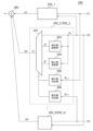
- the foldback processing section 252 includes a maximum side calculation section 253, a minimum side calculation section 254, a minimum side determination section 255, a maximum side determination section 256, and a multiplexer 257.
- the minimum side determination unit 255 compares the value p i-1 of the digital signal Di-1 with the minimum threshold value THmin i-1 , and outputs the comparison result.
- the maximum side determination unit 256 compares the value p i+1 of the digital signal Di+1 with the maximum threshold value THmax i+1 , and outputs the comparison result.
- Multiplexer 257 selects p'' when p i-1 ⁇ THmin i-1 . Multiplexer 257 selects p' when p i+1 >THmax i+1 . Multiplexer 257 selects p i when p i-1 >THmin i-1 and p i+1 >THmax i+1 .
- the combining section 260 adds the outputs of the plurality of return processing sections 252_1 to 252_3 to generate a feedback signal PFB .
- the combining unit 260 may perform simple addition or weighted addition.
- FIG. 9 is a block diagram of a folding processing unit 252a according to a modified example.
- the loopback processing unit 252a stops the loopback process when both the servo control position command PREF (target value) and the position detection signal are included in the loopback target area.
- the folding processing section 252a includes a target value determining section 258 and a window determining section 259 in addition to the folding processing section 252 of FIG.
- the target value determining unit 258 determines whether the target value PREF is included in a predetermined range near the turning point.
- the window determination unit 259 determines whether the value p i of the digital signal Di is included in a predetermined range near the maximum value pmax i or within a predetermined range near the minimum value pmin i .
- the output of the AND gate A1 becomes high, and the multiplexer 257 selects the value of the digital signal Di. Select and output p i .
- the window determination unit 259 may determine whether the value p i +1 of the digital signal Di+ 1 is included in a predetermined range instead of the value p i of the digital signal Di. Similarly, the window determination unit 259 may determine whether the value p i -1 of the digital signal Di-1 is included in a predetermined range instead of the value p i of the digital signal Di.
- the camera module 100 has a camera shake correction mechanism using the camera shake correction lens 104, but the camera shake correction mechanism is not limited to one based on lens shift. Further, in the embodiment, a position control system for an image stabilization mechanism has been described, but the present disclosure is not limited thereto, and can also be applied to a position control system for autofocus.
- An actuator driver that drives an actuator that positions a movable part, Receives n Hall signals from a plurality of n Hall elements (n ⁇ 2), converts the n Hall signals into n digital signals, and converts the movable part based on the n digital signals.
- a position detection unit that generates a feedback signal indicating the position of the a servo controller that generates a control signal so that the feedback signal approaches a target value;
- a drive unit that applies a drive signal to the voice coil motor in accordance with the control signal; Equipped with
- the position detection section is an actuator driver that folds back each of the n digital signals at a local maximum value and a local minimum value, and synthesizes the folded digital signals to generate the feedback signal.
- the position detection section is The maximum value pmax i of the i-th (1 ⁇ i ⁇ n-1) digital signal, and the value p i+ 1 of the (i+1)-th digital signal when the i-th digital signal takes the maximum value pmax i .
- the actuator driver according to 2.
- the position detection section is The minimum value pmin j of the j-th ((2 ⁇ j ⁇ n) digital signal, and the value p j- of the (j-1)th digital signal when the j-th digital signal takes the minimum value pmin j.
- the minimum threshold value THmin j ⁇ 1 which is 1 , is maintained.
- the value p j-1 of the (j-1)th digital signal is smaller than the minimum threshold THmin j-1
- the servo controller is an error detector that generates an error between the target value and the feedback signal; a proportional-integral controller subject to the error;
- the actuator driver according to any one of items 1 to 4, comprising:
- a method for detecting the position of a movable part positioned by an actuator comprising: arranging a plurality of n (n ⁇ 2) Hall elements along the stroke direction of the movable part; Converting n Hall signals generated by the n Hall elements into n digital signals; folding each of the n digital signals at a local maximum value and a local minimum value, and synthesizing the folded digital signals to generate a position detection signal; A method of providing.
- the method according to item 12 comprising:
- the step of generating the position detection signal includes: The minimum value pmin j of the j-th ((2 ⁇ j ⁇ n) digital signal, and the value p j- of the (j-1)th digital signal when the j-th digital signal takes the minimum value pmin j. maintaining a minimum threshold THmin j-1 equal to 1 ;
- the value p j-1 of the (j-1)th digital signal is smaller than the minimum threshold THmin j-1 , the value p j of the j-th digital signal is set to 2 ⁇ pmin j ⁇ p j. the step of converting;
- the present disclosure relates to an actuator driver and a camera module using the same.
Landscapes
- Physics & Mathematics (AREA)
- Engineering & Computer Science (AREA)
- General Physics & Mathematics (AREA)
- Multimedia (AREA)
- Signal Processing (AREA)
- Optics & Photonics (AREA)
- Power Engineering (AREA)
- Adjustment Of Camera Lenses (AREA)
Abstract
アクチュエータドライバ200は、可動部105を位置決めするアクチュエータ106を駆動する。位置検出部240は、複数n個(n≧2)のホール素子H1~H3からのn個のホール信号HS1~HS3を受け、n個のホール信号HS1~HS3をn個のデジタル信号D1~D3に変換し、n個のデジタル信号D1~D3にもとづいて、可動部105の位置を示すフィードバック信号PFBを生成する。位置検出部240は、n個のデジタル信号D1~D3それぞれを、極大値および極小値で折り返し、折り返した後のデジタル信号を合成して、フィードバック信号PFBを生成する。
Description
本開示は、アクチュエータドライバおよびこれを用いたカメラモジュールに関する。
近年、スマートフォンなどの電子機器に搭載されるカメラモジュールに、光学手ぶれ補正(OIS:Optical Image Stabilizer)の採用が進められている。光学手ぶれ補正付きのカメラモジュールは、イメージセンサ、イメージセンサの撮像面と平行なXY平面内で移動可能なレンズ(手ブレ補正用レンズと称する)、レンズを位置決めするアクチュエータ、アクチュエータを制御するアクチュエータドライバを備える。ジャイロセンサなどのブレ検出手段によってブレが検出されると、アクチュエータドライバは、ブレが相殺されるようにアクチュエータを駆動し、レンズをシフトさせる。
ホール素子の出力(ホール信号)は、理想的には可動部の位置に対して単調に変化し、より理想的には、線形に変化することが期待される。ところが、可動部のストローク長が長くなると、ホール信号は、位置に対して極大点、極小点を有する。このため、可動部の可動範囲が広いモジュールでは、可動範囲全体を、1個のホール素子でカバーすることができない。
本開示は係る状況においてなされたものであり、その例示的な目的のひとつは、長いストローク長を有するアクチュエータとの組み合わせにおいて、可動部の位置を検出可能なアクチュエータドライバおよびカメラモジュールの提供にある。
本開示のある態様は、可動部を位置決めするアクチュエータを駆動するアクチュエータドライバに関する。アクチュエータドライバは、複数n個(n≧2)のホール素子からのn個のホール信号を受け、n個のホール信号をn個のデジタル信号に変換し、n個のデジタル信号にもとづいて、可動部の位置を示すフィードバック信号を生成する位置検出部と、フィードバック信号が目標値に近づくように、制御信号を生成するサーボコントローラと、制御信号に応じた駆動信号をボイスコイルモータに印加する駆動部と、を備える。位置検出部は、n個のデジタル信号それぞれを極大値および極小値で折り返し、折り返した後のデジタル信号を合成して、フィードバック信号を生成する。
本開示の別の態様は、アクチュエータによって位置決めされる可動部の位置検出方法に関する。この方法は、可動部のストローク方向に沿って、複数n個(n≧2)のホール素子を配置するステップと、n個のホール素子が生成するn個のホール信号をn個のデジタル信号に変換するステップと、n個のデジタル信号それぞれを極大値および極小値で折り返し、折り返した後のデジタル信号を合成して、位置検出信号を生成するステップと、を備える。
なお、以上の構成要素を任意に組み合わせたもの、構成要素や表現を、方法、装置、システムなどの間で相互に置換したものもまた、本発明あるいは本開示の態様として有効である。さらに、この項目(課題を解決するための手段)の記載は、本発明の欠くべからざるすべての特徴を説明するものではなく、したがって、記載されるこれらの特徴のサブコンビネーションも、本発明たり得る。
本開示によれば、長いストローク長を有するアクチュエータとの組み合わせにおいて、可動部の位置を検出できる。
(実施形態の概要)
本開示のいくつかの例示的な実施形態の概要を説明する。この概要は、後述する詳細な説明の前置きとして、実施形態の基本的な理解を目的として、1つまたは複数の実施形態のいくつかの概念を簡略化して説明するものであり、発明あるいは開示の広さを限定するものではない。この概要は、考えられるすべての実施形態の包括的な概要ではなく、すべての実施形態の重要な要素を特定することも、一部またはすべての態様の範囲を線引きすることも意図していない。便宜上、「一実施形態」は、本明細書に開示するひとつの実施形態(実施例や変形例)または複数の実施形態(実施例や変形例)を指すものとして用いる場合がある。
本開示のいくつかの例示的な実施形態の概要を説明する。この概要は、後述する詳細な説明の前置きとして、実施形態の基本的な理解を目的として、1つまたは複数の実施形態のいくつかの概念を簡略化して説明するものであり、発明あるいは開示の広さを限定するものではない。この概要は、考えられるすべての実施形態の包括的な概要ではなく、すべての実施形態の重要な要素を特定することも、一部またはすべての態様の範囲を線引きすることも意図していない。便宜上、「一実施形態」は、本明細書に開示するひとつの実施形態(実施例や変形例)または複数の実施形態(実施例や変形例)を指すものとして用いる場合がある。
一実施形態に係るアクチュエータドライバは、可動部を位置決めするアクチュエータを駆動する。アクチュエータドライバは、複数n個(n≧2)のホール素子からのn個のホール信号を受け、n個のホール信号をn個のデジタル信号に変換し、n個のデジタル信号にもとづいて、可動部の位置を示すフィードバック信号を生成する位置検出部と、フィードバック信号が目標値に近づくように、制御信号を生成するサーボコントローラと、制御信号に応じた駆動信号をボイスコイルモータに印加する駆動部と、を備える。位置検出部は、n個のデジタル信号それぞれを極大値および極小値で折り返し、折り返した後のデジタル信号を合成して、フィードバック信号を生成する。
この構成によれば、可動部のストローク方向に、複数のホール素子を並べて配置し、複数のホール信号を合成することで、長いストローク長にわたり、可動子の位置を検出できるようになる。ここで、ホール信号が極大値や極小値を持つ場合に、複数のホール信号を単純加算して合成すると、合成後の信号の傾きが非常に小さい領域が存在することとなり、感度の低下が問題となる。上記構成では、ホール信号に応じたデジタル信号を、その極大値および極小値で折り返すことにより、合成後のデジタル信号の傾きが小さくなりすぎるのを防止でき、位置検出感度を高めることができる。
一実施形態において、位置検出部は、i番目(1≦i≦n-1)のデジタル信号の極大値pmaxiと、i番目のデジタル信号が極大値pmaxiをとるときの(i+1)番目のデジタル信号の値pi+1である極大しきい値THmaxi+1と、を保持しており、(i+1)番目のデジタル信号の値pi+1が、極大しきい値THmaxi+1より大きいとき、i番目のデジタル信号の値piを、pi’=2×pmaxi-piに変換して折り返す。
一実施形態において、位置検出部は、目標値が所定の範囲に含まれており、かつデジタル信号の値piが極大値pmaxiを含む所定の範囲に含まれるとき、pi’=piとして出力してもよい。
一実施形態において、位置検出部は、目標値が所定の範囲に含まれており、かつデジタル信号の値pi+1が、極大しきい値THmaxi+1を含む所定範囲に含まれるとき、pi’=piとして出力してもよい。
一実施形態において、位置検出部は、j番目((2≦j≦n)のデジタル信号の極小値pminjと、j番目のデジタル信号が極小値pminjをとるときの(j-1)番目のデジタル信号の値pj-1である極小しきい値THminj-1と、を保持しており、(j-1)番目のデジタル信号の値pj-1が、極小しきい値THminj-1より小さいとき、j番目のデジタル信号の値pjを、2×pminj-pjに変換してもよい。
ホール信号にもとづくデジタル信号と目標値の両方が、折り返し点の近傍の値を有する状況では、デジタル信号が折り返し点を跨ぐように変化すると、フィードバック制御が不安定になるおそれがある。そこでこのような状況では、折り返し処理をキャンセルすることで、安定なフィードバック制御が可能となる。
一実施形態において、位置検出部は、目標値が所定の範囲に含まれており、かつデジタル信号の値pjが極小値pminjを含む所定範囲に含まれるとき、pj’=pjとして出力してもよい。
一実施形態において、位置検出部は、目標値が所定の範囲に含まれており、かつデジタル信号の値pj-1が、極小しきい値THminj-1を含む所定範囲に含まれるとき、pj’=pjとして出力してもよい。
一実施形態において、サーボコントローラは、目標値とフィードバック信号の誤差を生成する誤差検出器と、誤差を受ける比例積分制御器と、を含んでもよい。
一実施形態において、アクチュエータドライバは、ひとつの半導体基板に一体集積化されてもよい。「一体集積化」とは、回路の構成要素のすべてが半導体基板上に形成される場合や、回路の主要構成要素が一体集積化される場合が含まれ、回路定数の調節用に一部の抵抗やキャパシタなどが半導体基板の外部に設けられていてもよい。回路を1つのチップ上に集積化することにより、回路面積を削減することができるとともに、回路素子の特性を均一に保つことができる。
一実施形態に係るカメラモジュールは、イメージセンサと、イメージセンサへの入射光路上に設けられた手ブレ補正機構と、手ブレ補正機構の可動部を位置決めするアクチュエータと、アクチュエータドライバと、を備えてもよい。
一実施形態に係るカメラモジュールは、イメージセンサと、イメージセンサへの入射光路上に設けられた手ブレ補正レンズと、手ブレ補正レンズを含む可動部を位置決めするアクチュエータと、上述のいずれかのアクチュエータドライバと、を備える。
(実施形態)
以下、好適な実施形態について、図面を参照しながら説明する。各図面に示される同一または同等の構成要素、部材、処理には、同一の符号を付するものとし、適宜重複した説明は省略する。また、実施形態は、開示および発明を限定するものではなく例示であって、実施形態に記述されるすべての特徴やその組み合わせは、必ずしも開示および発明の本質的なものであるとは限らない。
以下、好適な実施形態について、図面を参照しながら説明する。各図面に示される同一または同等の構成要素、部材、処理には、同一の符号を付するものとし、適宜重複した説明は省略する。また、実施形態は、開示および発明を限定するものではなく例示であって、実施形態に記述されるすべての特徴やその組み合わせは、必ずしも開示および発明の本質的なものであるとは限らない。
本明細書において、「部材Aが、部材Bと接続された状態」とは、部材Aと部材Bが物理的に直接的に接続される場合のほか、部材Aと部材Bが、それらの電気的な接続状態に実質的な影響を及ぼさない、あるいはそれらの結合により奏される機能や効果を損なわせない、その他の部材を介して間接的に接続される場合も含む。
同様に、「部材Cが、部材Aと部材Bの間に設けられた状態」とは、部材Aと部材C、あるいは部材Bと部材Cが直接的に接続される場合のほか、それらの電気的な接続状態に実質的な影響を及ぼさない、あるいはそれらの結合により奏される機能や効果を損なわせない、その他の部材を介して間接的に接続される場合も含む。
図1は、手振れ補正機能を備えるカメラモジュールのブロック図である。カメラモジュール100は、イメージセンサ102、手ブレ補正レンズ104、第1アクチュエータ106_1、第2アクチュエータ106_2、アクチュエータドライバ200、位置検出素子110_1,110_2、ブレ検出手段112、CPU(Central Processing Unit)114を備える。カメラモジュール100はその他、オートフォーカス用のレンズ、アクチュエータなどを備えるが、図1では省略している。
理解の容易化のため、手ブレ補正レンズ104の光軸方向をZ軸にとるものとする。また、カメラモジュール100が、図1の姿勢にあるときの、左右方向をX軸、上下方向をY軸にとるものとする。X軸を第1軸、Y軸を第2軸とも表記する。
手ブレ補正レンズ104は、イメージセンサ102に入射する光の光路上に配置される。イメージセンサ102は、CMOSセンサやCCDであり、手ブレ補正レンズ104を透過した像を撮影する。
手ブレ補正レンズ104は、イメージセンサ102の撮像面と平行な面内(XY平面)において、X方向およびY方向に移動可能な状態で支持されている。第1アクチュエータ106_1は、手ブレ補正レンズ104を含む可動部105を第1軸(X軸)方向に位置決めし、第2アクチュエータ106_2は、可動部105を第2軸(Y軸)方向に位置決めする。第1アクチュエータ106_1および第2アクチュエータ106_2は、リニアアクチュエータであり、たとえばボイスコイルモータが用いられる。手ブレ補正レンズ104を含む可動部105は、第1軸方向、第2軸方向それぞれについて、可動範囲が機械的に制約されている。可動範囲の端部を、メカ端と称する。第1軸方向について、正方向と負方向それぞれに、メカ端が存在し、第2軸方向についても正方向と負方向それぞれに、メカ端が存在する。
ブレ検出手段112は、カメラモジュール100のブレを検出し、ブレを示すブレ検出信号S1を生成する。ブレ検出手段112はたとえばジャイロセンサであり、カメラモジュール100のX軸周りの角速度ωX、Y軸周りの角速度ωY、Z軸周りの角速度ωZを検出する。手ブレ補正レンズ104のX軸方向の位置が制御することにより、Y軸周りの回転(ブレ)を補正することができ、手ブレ補正レンズ104のY軸方向の位置が制御することにより、X軸周りの回転(ブレ)を補正することができる。ブレ検出信号S1は、少なくとも2軸の角速度ωX,ωYを含む。
アクチュエータドライバ200は、ブレ検出手段112が検出したブレ検出信号S1にもとづいて、ブレが相殺されるように、手ブレ補正レンズ104の変位の目標値を示すターゲットコード(位置指令)を生成する。アクチュエータドライバ200は、内部で生成したターゲットコードにもとづいて、第1アクチュエータ106_1および第2アクチュエータ106_2それぞれに対する駆動信号S2_1,S2_2を生成する。アクチュエータ106_i(i=1,2)は、対応する駆動信号S2_iに応じて手ブレ補正レンズ104を位置決めする。
手振れ補正では、手ブレ補正レンズ104を正確に位置決めする必要があるため、フィードバック制御(クローズドループ制御)が採用される。位置検出素子110_1,110_2はそれぞれ、手ブレ補正レンズ104の第1軸方向の位置(変位量)PXおよび第2軸方向の位置(変位量)PYを示す位置検出信号S3_1,S3_2を生成する。位置検出素子110はたとえばホールセンサなどを用いることができる。
アクチュエータドライバ200は、手ブレが補正されるように、第1アクチュエータ106_1および第2アクチュエータ106_2を駆動する。具体的には第1モードにおいて、アクチュエータドライバ200は、第1位置検出信号S3_1の示す手ブレ補正レンズ104の位置PXが、ターゲットコードが示す目標位置PX(REF)と一致するように、駆動信号S2_1をフィードバック制御する。同様に、アクチュエータドライバ200は、第2位置検出信号S3_2の示す手ブレ補正レンズ104の位置PYが、ターゲットコードが示す目標位置PY(REF)と一致するように、駆動信号S2_2をフィードバック制御する。
以上がカメラモジュール100の全体の構成である。続いて、アクチュエータドライバ200について説明する。
図2は、アクチュエータドライバ200のブロック図である。アクチュエータドライバ200は、制御部210、第1駆動部220_1および第2駆動部220_2を備える。ジャイロセンサ112Aは、図1のブレ検出手段112であり、カメラモジュール100の角速度を検出する。
制御部210は、位置指令生成部212、第1サーボコントローラ230_1、第2サーボコントローラ230_2、第1位置検出部240_1、第2位置検出部240_2を備える。
位置指令生成部212は、第1モードにおいて、ジャイロセンサ112Aが生成するブレ検出信号S1を受け、X軸およびY軸それぞれについて、ブレを相殺することができる手ブレ補正レンズ104の位置を示す位置指令XREF,YREFを生成する。たとえば位置指令生成部212は、X軸周りの角速度ωXを積分して所定のゲインを乗算することにより、位置指令XREFを生成する。同様に、位置指令生成部212は、Y軸周りの角速度ωYを積分して所定のゲインを乗算することにより、位置指令YREFを生成する。
位置検出素子110_1が生成する位置検出信号S3_1は、第1位置検出部240_1に入力される。第1位置検出部240_1は、位置検出信号S3_1にもとづいて、アクチュエータ106_1の可動子の位置を示すフィードバック信号XFBを生成する。
同様に、位置検出素子110_2が生成する位置検出信号S3_2は、第2位置検出部240_2に入力される。第2位置検出部240_2は、位置検出信号S3_2にもとづいて、アクチュエータ106_2の可動子の位置を示すフィードバック信号YFBを生成する。フィードバック信号XFB,YFBはそれぞれ、可動部105のX方向、Y方向の位置(X座標,Y座標)を示す。
第1サーボコントローラ230_1は、フィードバック信号XFBと位置指令XREFの誤差がゼロに近づくように、制御信号S4_1を生成する。第1駆動部220_1は、制御信号S4_1に応じた駆動信号S2_1を生成する。制御信号S4_1はたとえば電流指令であり、第1駆動部220_1は、制御信号S4_1に応じた電流量の駆動電流を、第1アクチュエータ106_1に供給する。あるいは制御信号S4_1は電圧指令であり、第1駆動部220_1は、制御信号S4_1に応じた電圧レベルの駆動電圧を、第1アクチュエータ106_1に供給する。
同様に、第2サーボコントローラ230_2は、位置検出素子110_2が生成する位置検出信号S3_2を、可動部105のY座標を示すフィードバック信号YFBとして受ける。第2サーボコントローラ230_2は、フィードバック信号YFBと位置指令YREFの誤差がゼロに近づくように、制御信号S4_2を生成する。第2駆動部220_2は、制御信号S4_2に応じた駆動信号S2_2を生成する。
図2において、アクチュエータ106_1に対応するアクチュエータドライバ200の構成(220_1,230_1,240_1)と、アクチュエータ106_2に対応するアクチュエータドライバ200の構成(220_2,230_2,240_2)は同様である。
図3は、実施形態に係るアクチュエータドライバ200のブロック図である。図3におけるサーボコントローラ230は、図2の第1サーボコントローラ230_1または第2サーボコントローラ230_2に対応する。図3におけるPは、図2のXまたはYである。図3における駆動部220は、図2の第1駆動部220_1または第2駆動部220_2に対応する。図3における位置検出部240は、図2の第1位置検出部240_1または第2位置検出部240_2に対応する。
サーボコントローラ230は、誤差検出器232、補償器234を備える。誤差検出器232は、位置指令PREFと、可動部105の位置を示すフィードバック信号PFBとの誤差errを生成する。誤差検出器232は、減算器で構成できる。
補償器234は、誤差errに応じて、制御信号ctrlを生成する。補償器234をサーボフィルタとも称する。補償器234は、たとえばPI(比例・積分)制御器であり、誤差errに比例ゲインkpを乗算した値と、誤差errの積分値に積分ゲインkiを乗算した値と、を加算し、制御信号ctrlを生成してもよい。補償器234は、PID(比例・積分・微分制御器)であってもよい。
駆動部220は、制御信号S4(ctrl)に応じた駆動信号S2を、アクチュエータ106のボイスコイルに印加する。
本実施形態において、位置検出素子110は、複数n個(n≧2)のホール素子H1~Hnを含む。この例ではn=3としている。n個のホール素子H1~Hnは、アクチュエータ106のストローク方向に沿って配置される。
各ホール素子Hi(1≦i≦n)は、アクチュエータ106の可動部の位置に応じたホール信号HSiを生成する。複数のホール信号SH1~SH3は、アクチュエータドライバ200のピンADC1~ADC3に入力される。
位置検出部240は、n個のホール信号HS1~HS3を受け、n個のホール信号をn個のデジタル信号D1~Dnに変換する。そして、デジタル信号D1~Dnにもとづいて、可動部の位置を示すフィードバック信号PFBを生成する。
位置検出部240は、たとえばn個のA/Dコンバータ242_1~242_nと、演算処理部250を備える。i番目のA/Dコンバータ242_iは、対応するホール信号HSiをデジタル信号Diに変換する。なお1個のA/Dコンバータ242によって、時分割で複数のホール信号HS1~HSnをデジタル信号D1~Dnに変換してもよい。位置検出部240は、ホール信号HSを増幅するホールアンプをさらに含んでもよい。
演算処理部250は、n個のデジタル信号D1~Dnにもとづいて、フィードバック信号PFBを生成する。
具体的には演算処理部250は、n個のデジタル信号D1~Dnそれぞれを、極大値および極小値で折り返す。そして折り返した後のデジタル信号D1’~Dn’を合成して、フィードバック信号PFBを生成する。
以上がアクチュエータドライバ200の構成である。続いてその動作を説明する。
図4は、図3の位置検出部240の折り返し処理を説明する図である。横軸は、アクチュエータ106の可動部の位置Pを表し、縦軸はデジタル信号の値を示す。図4には、デジタル信号D1~D3と、折り返し後のデジタル信号D1’~D3’が示される。
デジタル信号D1の一部分は、その極大値pmax1を基準として折り返される。デジタル信号D2は、その一部分が極小値pmin2を基準として折り返され、別の一部分が極大値pmax2を基準として折り返される。デジタル信号D3の一部分は、その極小値pmin3を基準として折り返される。折り返し後のデジタル信号D1’~D3’はいずれも、ストローク範囲内で、位置Pに対して単調増加することが保証される。
図5は、図3の位置検出部240の合成処理を説明する図である。横軸は、アクチュエータ106の可動部の位置Pを表し、縦軸はデジタル信号の値を示す。図5の上段は、折り返し処理後のデジタル信号D1’~D3’を示し、図5の下段は、デジタル信号D1’~D3’を合成して得られるフィードバック信号PFBを示す。単調増加する複数のデジタル信号D1’~D3’を加算して得られるフィードバック信号PFBは、当然ながら、位置Pに対して単調増加する。
実施形態に係るアクチュエータドライバ200によれば、長いストローク長を有するアクチュエータとの組み合わせにおいて、可動部の位置を正確に検出できる。
ここで、デジタル信号Diにおける極大値または極小値は、折り返し後のデジタル信号Di’では変曲点となる。デジタル信号Di’は、変曲点の近傍で傾きが小さくなるが、それに対応する別のデジタル信号Di±1’は、大きな傾きを有している。したがって、合成後のフィードバック信号PFBは、デジタル信号D1~D3の極大値、極小値に対応する部分においても、十分に大きな傾きを有しており、十分な位置検出感度を有している。したがって、ストローク範囲全体にわたって、正確な位置検出、ひいては正確な位置制御が可能となる。
本開示は、図3のブロック図や回路図として把握され、あるいは上述の説明から導かれるさまざまな装置、方法に及ぶものであり、特定の構成に限定されるものではない。以下、本開示の範囲を狭めるためではなく、本開示や本発明の本質や動作の理解を助け、またそれらを明確化するために、より具体的な構成例や実施例を説明する。
続いて、演算処理部250の具体的な構成例および処理を説明する。
図6は、演算処理部250による極大値に関する折り返し処理を説明する図である。図6には、i番目(1≦i≦n-1)のデジタル信号Diの極大値に関する折り返しを示している。piは、デジタル信号Diの値を表す。演算処理部250は、値pmaxiと、極大しきい値THmaxi+1を保持している。pmaxiは、i番目(1≦i≦n-1)のデジタル信号Diの極大値である。極大しきい値THmaxi+1は、i番目のデジタル信号Diが極大値pmaxiをとるときの(i+1)番目のデジタル信号Di+1の値pi+1である。
演算処理部250は、(i+1)番目のデジタル信号の値pi+1が、極大しきい値THmaxi+1より大きいとき、折り返し処理を行う。折り返し後のデジタル信号Di’の値pi’は、以下の式で表すことができる。
pi’=2×pmaxi-pi
pi’=2×pmaxi-pi
図7は、演算処理部250による極小値に関する折り返し処理を説明する図である。図7には、j番目(2≦i≦n)のデジタル信号Djの極大値に関する折り返しを示している。演算処理部250は、値pminjと、極小しきい値THminj-1を保持している。pminjは、j番目のデジタル信号Djの極小値である。極小しきい値THminj-1は、j番目のデジタル信号Djが極小値pminjをとるときの、(j-1)番目のデジタル信号Dj-1の値pj-1である。
演算処理部250は、(j-1)番目のデジタル信号の値pj-1が、極大しきい値THminj-1より小さいとき、折り返し処理を行う。折り返し後のデジタル信号Dj’の値pj’は、以下の式で表すことができる。
pj’=2×pminj-pj
pj’=2×pminj-pj
図8は、演算処理部250の構成例を示すブロック図である。演算処理部250は、複数の折り返し処理部252_1~252_3および合成部260を含む。折り返し処理部252_iは、対応するデジタル信号Diを極大値、極小値それぞれに関して折り返す。なお、デジタル信号D1に関しては、極小値における折り返しは不要であり、デジタル信号Dn(D3)に関しては、極大値における折り返しは不要である。
極大値に関する折り返しと、極小値に関する折り返しの両方を行う折り返し処理部252_i(2≦i≦n-1)に着目する。折り返し処理部252は、極大側演算部253、極小側演算部254、極小側判定部255、極大側判定部256、マルチプレクサ257を含む。
極大側演算部253および極小側演算部254はそれぞれ、以下の値を計算する。
p’=2×pmaxi-pi
p''=2×pminj-pj
2つの値p’、p''は、デジタル信号Diの値piとともに、マルチプレクサ257に入力される。
p’=2×pmaxi-pi
p''=2×pminj-pj
2つの値p’、p''は、デジタル信号Diの値piとともに、マルチプレクサ257に入力される。
極小側判定部255は、デジタル信号Di-1の値pi-1を、極小しきい値THmini-1と比較し、比較結果を出力する。極大側判定部256は、デジタル信号Di+1の値pi+1を、極大しきい値THmaxi+1と比較し、比較結果を出力する。
マルチプレクサ257は、pi-1<THmini-1であるとき、p''を選択する。マルチプレクサ257は、pi+1>THmaxi+1であるとき、p'を選択する。マルチプレクサ257は、pi-1>THmini-1かつpi+1>THmaxi+1であるとき、piを選択する。
合成部260は、複数の折り返し処理部252_1~252_3の出力を加算し、フィードバック信号PFBを生成する。合成部260は、単純加算を行ってもよいし、重み付け加算を行ってもよい。
図9は、変形例に係る折り返し処理部252aのブロック図である。この折り返し処理部252aは、サーボ制御の位置指令PREF(目標値)と、位置検出信号の両方が、折り返し対象の領域に含まれる場合に、折り返し処理を停止する。
折り返し処理部252aは、図8の折り返し処理部252に加えて、目標値判定部258およびウィンドウ判定部259を含む。目標値判定部258は、目標値PREFが折り返し点の近傍の所定範囲に含まれるか否かを判定する。ウィンドウ判定部259は、デジタル信号Diの値piが、極大値pmaxiの近傍の所定範囲、または極小値pminiの近傍の所定範囲に含まれるか否かを判定する。目標値PREFが所定範囲に含まれており、かつ、デジタル信号Diの値piが所定範囲に含まれている場合、ANDゲートA1の出力がハイとなり、マルチプレクサ257は、デジタル信号Diの値piを選択して出力する。
ホール信号SHiにもとづくデジタル信号Diと、目標値PREFの両方が、折り返し点の近傍の値を有する状況では、デジタル信号Diが折り返し点を跨ぐように変化すると、フィードバック制御が不安定になるおそれがある。そこでこのような状況では、折り返し処理をキャンセルすることで、安定なフィードバック制御が可能となる。
図9において、ウィンドウ判定部259は、デジタル信号Diの値piに代えて、デジタル信号Di+1の値pi+1が所定範囲に含まれているかを判定してもよい。同様にウィンドウ判定部259は、デジタル信号Diの値piに代えて、デジタル信号Di-1の値pi-1が所定範囲に含まれているかを判定してもよい。
実施形態では、手ブレ補正レンズ104による手ブレ補正機構を有するカメラモジュール100について説明したが、手ブレ補正機構はレンズシフトによるものに限定されない。また実施形態では、手ブレ補正機構の位置制御システムを説明したが、本開示はそれに限定されず、オートフォーカス用の位置制御システムにも適用可能である。
本開示に係る実施形態について、具体的な用語を用いて説明したが、この説明は、理解を助けるための例示に過ぎず、本開示あるいは請求の範囲を限定するものではない。本発明の範囲は、請求の範囲によって規定されるものであり、したがって、ここでは説明しない実施形態、実施例、変形例も、本発明の範囲に含まれる。
(付記)
本明細書に開示される技術は、一側面において以下のように把握できる。
本明細書に開示される技術は、一側面において以下のように把握できる。
(項目1)
可動部を位置決めするアクチュエータを駆動するアクチュエータドライバであって、
複数n個(n≧2)のホール素子からのn個のホール信号を受け、前記n個のホール信号をn個のデジタル信号に変換し、前記n個のデジタル信号にもとづいて、前記可動部の位置を示すフィードバック信号を生成する位置検出部と、
前記フィードバック信号が目標値に近づくように、制御信号を生成するサーボコントローラと、
前記制御信号に応じた駆動信号をボイスコイルモータに印加する駆動部と、
を備え、
前記位置検出部は、前記n個のデジタル信号それぞれを極大値および極小値で折り返し、折り返した後のデジタル信号を合成して、前記フィードバック信号を生成する、アクチュエータドライバ。
可動部を位置決めするアクチュエータを駆動するアクチュエータドライバであって、
複数n個(n≧2)のホール素子からのn個のホール信号を受け、前記n個のホール信号をn個のデジタル信号に変換し、前記n個のデジタル信号にもとづいて、前記可動部の位置を示すフィードバック信号を生成する位置検出部と、
前記フィードバック信号が目標値に近づくように、制御信号を生成するサーボコントローラと、
前記制御信号に応じた駆動信号をボイスコイルモータに印加する駆動部と、
を備え、
前記位置検出部は、前記n個のデジタル信号それぞれを極大値および極小値で折り返し、折り返した後のデジタル信号を合成して、前記フィードバック信号を生成する、アクチュエータドライバ。
(項目2)
前記位置検出部は、
i番目(1≦i≦n-1)のデジタル信号の極大値pmaxiと、前記i番目のデジタル信号が前記極大値pmaxiをとるときの(i+1)番目のデジタル信号の値pi+1である極大しきい値THmaxi+1と、を保持しており、
(i+1)番目のデジタル信号の値pi+1が、前記極大しきい値THmaxi+1より大きいとき、前記i番目のデジタル信号の値piを、pi’=2×pmaxi-piに変換して折り返す、項目1に記載のアクチュエータドライバ。
前記位置検出部は、
i番目(1≦i≦n-1)のデジタル信号の極大値pmaxiと、前記i番目のデジタル信号が前記極大値pmaxiをとるときの(i+1)番目のデジタル信号の値pi+1である極大しきい値THmaxi+1と、を保持しており、
(i+1)番目のデジタル信号の値pi+1が、前記極大しきい値THmaxi+1より大きいとき、前記i番目のデジタル信号の値piを、pi’=2×pmaxi-piに変換して折り返す、項目1に記載のアクチュエータドライバ。
(項目3)
前記位置検出部は、
前記目標値が所定の範囲に含まれており、かつ前記デジタル信号の値piが前記極大値pmaxiを含む所定の範囲に含まれるとき、pi’=piとして出力する、項目2に記載のアクチュエータドライバ。
前記位置検出部は、
前記目標値が所定の範囲に含まれており、かつ前記デジタル信号の値piが前記極大値pmaxiを含む所定の範囲に含まれるとき、pi’=piとして出力する、項目2に記載のアクチュエータドライバ。
(項目4)
前記位置検出部は、
前記目標値が所定の範囲に含まれており、かつ前記デジタル信号の値pi+1が、前記極大しきい値THmaxi+1を含む所定範囲に含まれるとき、pi’=piとして出力する、項目2に記載のアクチュエータドライバ。
前記位置検出部は、
前記目標値が所定の範囲に含まれており、かつ前記デジタル信号の値pi+1が、前記極大しきい値THmaxi+1を含む所定範囲に含まれるとき、pi’=piとして出力する、項目2に記載のアクチュエータドライバ。
(項目5)
前記位置検出部は、
j番目((2≦j≦n)のデジタル信号の極小値pminjと、前記j番目のデジタル信号が前記極小値pminjをとるときの(j-1)番目のデジタル信号の値pj-1である極小しきい値THminj-1と、を保持しており、
(j-1)番目のデジタル信号の値pj-1が、前記極小しきい値THminj-1より小さいとき、前記j番目のデジタル信号の値pjを、pj’=2×pminj-pjに変換する、項目1から4のいずれかに記載のアクチュエータドライバ。
前記位置検出部は、
j番目((2≦j≦n)のデジタル信号の極小値pminjと、前記j番目のデジタル信号が前記極小値pminjをとるときの(j-1)番目のデジタル信号の値pj-1である極小しきい値THminj-1と、を保持しており、
(j-1)番目のデジタル信号の値pj-1が、前記極小しきい値THminj-1より小さいとき、前記j番目のデジタル信号の値pjを、pj’=2×pminj-pjに変換する、項目1から4のいずれかに記載のアクチュエータドライバ。
(項目6)
前記位置検出部は、
前記目標値が所定の範囲に含まれており、かつ前記デジタル信号の値pjが前記極小値pminjを含む所定範囲に含まれるとき、pj’=pjとして出力する、項目5に記載のアクチュエータドライバ。
前記位置検出部は、
前記目標値が所定の範囲に含まれており、かつ前記デジタル信号の値pjが前記極小値pminjを含む所定範囲に含まれるとき、pj’=pjとして出力する、項目5に記載のアクチュエータドライバ。
(項目7)
前記位置検出部は、
前記目標値が所定の範囲に含まれており、かつ前記デジタル信号の値pj-1が、前記極小しきい値THminj-1を含む所定範囲に含まれるとき、pj’=pjとして出力する、項目5に記載のアクチュエータドライバ。
前記位置検出部は、
前記目標値が所定の範囲に含まれており、かつ前記デジタル信号の値pj-1が、前記極小しきい値THminj-1を含む所定範囲に含まれるとき、pj’=pjとして出力する、項目5に記載のアクチュエータドライバ。
(項目8)
前記サーボコントローラは、
前記目標値と前記フィードバック信号の誤差を生成する誤差検出器と、
前記誤差を受ける比例積分制御器と、
を含む、項目1から4のいずれかに記載のアクチュエータドライバ。
前記サーボコントローラは、
前記目標値と前記フィードバック信号の誤差を生成する誤差検出器と、
前記誤差を受ける比例積分制御器と、
を含む、項目1から4のいずれかに記載のアクチュエータドライバ。
(項目9)
ひとつの半導体基板に一体集積化される、項目1から4のいずれかに記載のアクチュエータドライバ。
ひとつの半導体基板に一体集積化される、項目1から4のいずれかに記載のアクチュエータドライバ。
(項目10)
イメージセンサと、
前記イメージセンサへの入射光路上に設けられた手ブレ補正機構と、
前記手ブレ補正機構の可動部を位置決めするアクチュエータと、
項目1から4のいずれかに記載のアクチュエータドライバと、
を備える、カメラモジュール。
イメージセンサと、
前記イメージセンサへの入射光路上に設けられた手ブレ補正機構と、
前記手ブレ補正機構の可動部を位置決めするアクチュエータと、
項目1から4のいずれかに記載のアクチュエータドライバと、
を備える、カメラモジュール。
(項目11)
項目10に記載のカメラモジュールを備える、電子機器。
項目10に記載のカメラモジュールを備える、電子機器。
(項目12)
アクチュエータによって位置決めされる可動部の位置検出方法であって、
前記可動部のストローク方向に沿って、複数n個(n≧2)のホール素子を配置するステップと、
前記n個のホール素子が生成するn個のホール信号をn個のデジタル信号に変換するステップと、
前記n個のデジタル信号それぞれを極大値および極小値で折り返し、折り返した後のデジタル信号を合成して、位置検出信号を生成するステップと、
を備える、方法。
アクチュエータによって位置決めされる可動部の位置検出方法であって、
前記可動部のストローク方向に沿って、複数n個(n≧2)のホール素子を配置するステップと、
前記n個のホール素子が生成するn個のホール信号をn個のデジタル信号に変換するステップと、
前記n個のデジタル信号それぞれを極大値および極小値で折り返し、折り返した後のデジタル信号を合成して、位置検出信号を生成するステップと、
を備える、方法。
(項目13)
前記位置検出信号を生成するステップは、
i番目(1≦i≦n-1)のデジタル信号piの極大値pmaxiと、前記i番目のデジタル信号が前記極大値pmaxiをとるときの(i+1)番目のデジタル信号の値pi+1である極大しきい値THmaxi+1と、を保持するステップと、
(i+1)番目のデジタル信号の値pi+1が、前記極大しきい値THmaxi+1より大きいとき、前記i番目のデジタル信号の値piを、pi’=2×pmaxi-piに変換して折り返すステップと、
を含む、項目12に記載の方法。
前記位置検出信号を生成するステップは、
i番目(1≦i≦n-1)のデジタル信号piの極大値pmaxiと、前記i番目のデジタル信号が前記極大値pmaxiをとるときの(i+1)番目のデジタル信号の値pi+1である極大しきい値THmaxi+1と、を保持するステップと、
(i+1)番目のデジタル信号の値pi+1が、前記極大しきい値THmaxi+1より大きいとき、前記i番目のデジタル信号の値piを、pi’=2×pmaxi-piに変換して折り返すステップと、
を含む、項目12に記載の方法。
(項目14)
前記位置検出信号を生成するステップは、
j番目((2≦j≦n)のデジタル信号の極小値pminjと、前記j番目のデジタル信号が前記極小値pminjをとるときの(j-1)番目のデジタル信号の値pj-1である極小しきい値THminj-1と、を保持するステップと、
(j-1)番目のデジタル信号の値pj-1が、前記極小しきい値THminj-1より小さいとき、前記j番目のデジタル信号の値pjを、2×pminj-pjに変換するステップと、
を含む、項目12または13に記載のアクチュエータドライバ。
前記位置検出信号を生成するステップは、
j番目((2≦j≦n)のデジタル信号の極小値pminjと、前記j番目のデジタル信号が前記極小値pminjをとるときの(j-1)番目のデジタル信号の値pj-1である極小しきい値THminj-1と、を保持するステップと、
(j-1)番目のデジタル信号の値pj-1が、前記極小しきい値THminj-1より小さいとき、前記j番目のデジタル信号の値pjを、2×pminj-pjに変換するステップと、
を含む、項目12または13に記載のアクチュエータドライバ。
本開示は、アクチュエータドライバおよびこれを用いたカメラモジュールに関する。
100 カメラモジュール
102 イメージセンサ
104 手ブレ補正レンズ
105 可動部
106 アクチュエータ
110 位置検出素子
112 ブレ検出手段
112A ジャイロセンサ
114 CPU
200 アクチュエータドライバ
210 制御部
212 位置指令生成部
230_1 第1サーボコントローラ
230_2 第2サーボコントローラ
220 駆動部
220_1 第1駆動部
220_2 第2駆動部
230 サーボコントローラ
232 誤差検出器
234 補償器
240 位置検出部
242 A/Dコンバータ
240_1 第1位置検出部
240_2 第2位置検出部
250 演算処理部
102 イメージセンサ
104 手ブレ補正レンズ
105 可動部
106 アクチュエータ
110 位置検出素子
112 ブレ検出手段
112A ジャイロセンサ
114 CPU
200 アクチュエータドライバ
210 制御部
212 位置指令生成部
230_1 第1サーボコントローラ
230_2 第2サーボコントローラ
220 駆動部
220_1 第1駆動部
220_2 第2駆動部
230 サーボコントローラ
232 誤差検出器
234 補償器
240 位置検出部
242 A/Dコンバータ
240_1 第1位置検出部
240_2 第2位置検出部
250 演算処理部
Claims (14)
- 可動部を位置決めするアクチュエータを駆動するアクチュエータドライバであって、
複数n個(n≧2)のホール素子からのn個のホール信号を受け、前記n個のホール信号をn個のデジタル信号に変換し、前記n個のデジタル信号にもとづいて、前記可動部の位置を示すフィードバック信号を生成する位置検出部と、
前記フィードバック信号が目標値に近づくように、制御信号を生成するサーボコントローラと、
前記制御信号に応じた駆動信号をボイスコイルモータに印加する駆動部と、
を備え、
前記位置検出部は、前記n個のデジタル信号それぞれを極大値および極小値で折り返し、折り返した後のデジタル信号を合成して、前記フィードバック信号を生成する、アクチュエータドライバ。 - 前記位置検出部は、
i番目(1≦i≦n-1)のデジタル信号の極大値pmaxiと、前記i番目のデジタル信号が前記極大値pmaxiをとるときの(i+1)番目のデジタル信号の値pi+1である極大しきい値THmaxi+1と、を保持しており、
(i+1)番目のデジタル信号の値pi+1が、前記極大しきい値THmaxi+1より大きいとき、前記i番目のデジタル信号の値piを、pi’=2×pmaxi-piに変換して折り返す、請求項1に記載のアクチュエータドライバ。 - 前記位置検出部は、
前記目標値が所定の範囲に含まれており、かつ前記デジタル信号の値piが前記極大値pmaxiを含む所定の範囲に含まれるとき、pi’=piとして出力する、請求項2に記載のアクチュエータドライバ。 - 前記位置検出部は、
前記目標値が所定の範囲に含まれており、かつ前記デジタル信号の値pi+1が、前記極大しきい値THmaxi+1を含む所定範囲に含まれるとき、pi’=piとして出力する、請求項2に記載のアクチュエータドライバ。 - 前記位置検出部は、
j番目((2≦j≦n)のデジタル信号の極小値pminjと、前記j番目のデジタル信号が前記極小値pminjをとるときの(j-1)番目のデジタル信号の値pj-1である極小しきい値THminj-1と、を保持しており、
(j-1)番目のデジタル信号の値pj-1が、前記極小しきい値THminj-1より小さいとき、前記j番目のデジタル信号の値pjを、pj’=2×pminj-pjに変換する、請求項1から4のいずれかに記載のアクチュエータドライバ。 - 前記位置検出部は、
前記目標値が所定の範囲に含まれており、かつ前記デジタル信号の値pjが前記極小値pminjを含む所定範囲に含まれるとき、pj’=pjとして出力する、請求項5に記載のアクチュエータドライバ。 - 前記位置検出部は、
前記目標値が所定の範囲に含まれており、かつ前記デジタル信号の値pj-1が、前記極小しきい値THminj-1を含む所定範囲に含まれるとき、pj’=pjとして出力する、請求項5に記載のアクチュエータドライバ。 - 前記サーボコントローラは、
前記目標値と前記フィードバック信号の誤差を生成する誤差検出器と、
前記誤差を受ける比例積分制御器と、
を含む、請求項1から4のいずれかに記載のアクチュエータドライバ。 - ひとつの半導体基板に一体集積化される、請求項1から4のいずれかに記載のアクチュエータドライバ。
- イメージセンサと、
前記イメージセンサへの入射光路上に設けられた手ブレ補正機構と、
前記手ブレ補正機構の可動部を位置決めするアクチュエータと、
請求項1から4のいずれかに記載のアクチュエータドライバと、
を備える、カメラモジュール。 - 請求項10に記載のカメラモジュールを備える、電子機器。
- アクチュエータによって位置決めされる可動部の位置検出方法であって、
前記可動部のストローク方向に沿って、複数n個(n≧2)のホール素子を配置するステップと、
前記n個のホール素子が生成するn個のホール信号をn個のデジタル信号に変換するステップと、
前記n個のデジタル信号それぞれを極大値および極小値で折り返し、折り返した後のデジタル信号を合成して、位置検出信号を生成するステップと、
を備える、方法。 - 前記位置検出信号を生成するステップは、
i番目(1≦i≦n-1)のデジタル信号piの極大値pmaxiと、前記i番目のデジタル信号が前記極大値pmaxiをとるときの(i+1)番目のデジタル信号の値pi+1である極大しきい値THmaxi+1と、を保持するステップと、
(i+1)番目のデジタル信号の値pi+1が、前記極大しきい値THmaxi+1より大きいとき、前記i番目のデジタル信号の値piを、pi’=2×pmaxi-piに変換して折り返すステップと、
を含む、請求項12に記載の方法。 - 前記位置検出信号を生成するステップは、
j番目((2≦j≦n)のデジタル信号の極小値pminjと、前記j番目のデジタル信号が前記極小値pminjをとるときの(j-1)番目のデジタル信号の値pj-1である極小しきい値THminj-1と、を保持するステップと、
(j-1)番目のデジタル信号の値pj-1が、前記極小しきい値THminj-1より小さいとき、前記j番目のデジタル信号の値pjを、2×pminj-pjに変換するステップと、
を含む、請求項12または13に記載のアクチュエータドライバ。
Priority Applications (1)
| Application Number | Priority Date | Filing Date | Title |
|---|---|---|---|
| JP2024540366A JPWO2024034404A1 (ja) | 2022-08-09 | 2023-07-26 |
Applications Claiming Priority (2)
| Application Number | Priority Date | Filing Date | Title |
|---|---|---|---|
| JP2022-127427 | 2022-08-09 | ||
| JP2022127427 | 2022-08-09 |
Publications (1)
| Publication Number | Publication Date |
|---|---|
| WO2024034404A1 true WO2024034404A1 (ja) | 2024-02-15 |
Family
ID=89851525
Family Applications (1)
| Application Number | Title | Priority Date | Filing Date |
|---|---|---|---|
| PCT/JP2023/027429 Ceased WO2024034404A1 (ja) | 2022-08-09 | 2023-07-26 | アクチュエータドライバおよびこれを用いたカメラモジュール、電子機器、可動部の位置検出方法 |
Country Status (2)
| Country | Link |
|---|---|
| JP (1) | JPWO2024034404A1 (ja) |
| WO (1) | WO2024034404A1 (ja) |
Citations (4)
| Publication number | Priority date | Publication date | Assignee | Title |
|---|---|---|---|---|
| JP2006108305A (ja) * | 2004-10-04 | 2006-04-20 | Nikon Corp | ベストフォーカス位置検出方法とその装置、露光方法とその装置及びデバイス製造方法 |
| JP2009151203A (ja) * | 2007-12-21 | 2009-07-09 | Sanyo Electric Co Ltd | 振動補正制御回路及びそれを備えた撮像装置 |
| JP2014126857A (ja) * | 2012-12-27 | 2014-07-07 | Canon Inc | 焦点調節装置及び方法、及び撮像装置 |
| JP2014228623A (ja) * | 2013-05-21 | 2014-12-08 | 株式会社ニコン | ブレ補正装置、レンズ鏡筒および撮影装置 |
-
2023
- 2023-07-26 JP JP2024540366A patent/JPWO2024034404A1/ja active Pending
- 2023-07-26 WO PCT/JP2023/027429 patent/WO2024034404A1/ja not_active Ceased
Patent Citations (4)
| Publication number | Priority date | Publication date | Assignee | Title |
|---|---|---|---|---|
| JP2006108305A (ja) * | 2004-10-04 | 2006-04-20 | Nikon Corp | ベストフォーカス位置検出方法とその装置、露光方法とその装置及びデバイス製造方法 |
| JP2009151203A (ja) * | 2007-12-21 | 2009-07-09 | Sanyo Electric Co Ltd | 振動補正制御回路及びそれを備えた撮像装置 |
| JP2014126857A (ja) * | 2012-12-27 | 2014-07-07 | Canon Inc | 焦点調節装置及び方法、及び撮像装置 |
| JP2014228623A (ja) * | 2013-05-21 | 2014-12-08 | 株式会社ニコン | ブレ補正装置、レンズ鏡筒および撮影装置 |
Also Published As
| Publication number | Publication date |
|---|---|
| JPWO2024034404A1 (ja) | 2024-02-15 |
Similar Documents
| Publication | Publication Date | Title |
|---|---|---|
| US10897574B2 (en) | Actuator driver, imaging device using the same, and imaging method | |
| KR102130205B1 (ko) | 촬상 장치 | |
| JP2018124582A (ja) | 手振れ補正装置及び手振れ補正回路並びに手振れ補正方法 | |
| US8754951B2 (en) | Control circuit for image-capturing device | |
| US11785341B2 (en) | Crosstalk correction method and actuator driver | |
| JP7192052B2 (ja) | 撮像装置およびアクチュエータドライバ | |
| US8325243B2 (en) | Image stabilization control circuit for correcting vibration-caused displacement of optical axis, and image pickup apparatus provided with the same | |
| US10473884B2 (en) | Drive circuit of voice coil motor, method for driving voice coil motor, lens module and electronic apparatus using the same | |
| JP6917799B2 (ja) | 撮像装置 | |
| WO2024034404A1 (ja) | アクチュエータドライバおよびこれを用いたカメラモジュール、電子機器、可動部の位置検出方法 | |
| WO2009110599A1 (ja) | 制御装置、位置決め装置、制御方法、及び計測装置 | |
| JP2023146476A (ja) | アクチュエータドライバおよびこれを用いたカメラモジュール、電子機器、アクチュエータの駆動方法 | |
| US8026949B2 (en) | Image stabilization control circuit for correcting vibration-caused displacement of optical axis, and image pickup apparatus provided with the same | |
| JP2023150359A (ja) | アクチュエータドライバ回路およびカメラモジュール、位置決めシステムのキャリブレーション方法 | |
| WO2023238672A1 (ja) | アクチュエータドライバおよびこれを用いたカメラモジュール、電子機器 | |
| JP6823496B2 (ja) | アクチュエータドライバおよび撮像装置 | |
| JP2023163732A (ja) | アクチュエータドライバおよびこれを用いたカメラモジュール、電子機器 | |
| JP2023178805A (ja) | アクチュエータドライバおよびその制御方法、それを用いたカメラモジュール、電子機器 | |
| JP4695558B2 (ja) | 自動焦点調節機能の付いたcmosイメージセンサ及びそれを含むカメラ装置 | |
| JP2023148661A (ja) | アクチュエータドライバおよびその制御方法、それを用いたカメラモジュール、電子機器 | |
| KR102393073B1 (ko) | Pid 제어를 이용하는 렌즈구동 방법에 있어서 적분계산을 제어하는 방법 및 이를 위한 장치 | |
| JP2019114920A (ja) | アクチュエータドライバ、及びこれを用いた撮像装置、及びキャリブレーション方法 | |
| JP2023090314A (ja) | アクチュエータドライバおよびこれを用いたカメラモジュール、電子機器 | |
| JP2023087505A (ja) | アクチュエータドライバ回路および撮像装置 | |
| CN120034739A (zh) | 致动器驱动器、照相机模块、电子设备 |
Legal Events
| Date | Code | Title | Description |
|---|---|---|---|
| 121 | Ep: the epo has been informed by wipo that ep was designated in this application |
Ref document number: 23852378 Country of ref document: EP Kind code of ref document: A1 |
|
| WWE | Wipo information: entry into national phase |
Ref document number: 2024540366 Country of ref document: JP |
|
| NENP | Non-entry into the national phase |
Ref country code: DE |
|
| 122 | Ep: pct application non-entry in european phase |
Ref document number: 23852378 Country of ref document: EP Kind code of ref document: A1 |