WO2024034164A1 - 電流センサ - Google Patents
電流センサ Download PDFInfo
- Publication number
- WO2024034164A1 WO2024034164A1 PCT/JP2023/006396 JP2023006396W WO2024034164A1 WO 2024034164 A1 WO2024034164 A1 WO 2024034164A1 JP 2023006396 W JP2023006396 W JP 2023006396W WO 2024034164 A1 WO2024034164 A1 WO 2024034164A1
- Authority
- WO
- WIPO (PCT)
- Prior art keywords
- bus bar
- magnetic detection
- current sensor
- detection section
- magnetic
- Prior art date
- Legal status (The legal status is an assumption and is not a legal conclusion. Google has not performed a legal analysis and makes no representation as to the accuracy of the status listed.)
- Ceased
Links
Images




Classifications
-
- G—PHYSICS
- G01—MEASURING; TESTING
- G01R—MEASURING ELECTRIC VARIABLES; MEASURING MAGNETIC VARIABLES
- G01R15/00—Details of measuring arrangements of the types provided for in groups G01R17/00 - G01R29/00, G01R33/00 - G01R33/26 or G01R35/00
- G01R15/14—Adaptations providing voltage or current isolation, e.g. for high-voltage or high-current networks
- G01R15/20—Adaptations providing voltage or current isolation, e.g. for high-voltage or high-current networks using galvano-magnetic devices, e.g. Hall-effect devices, i.e. measuring a magnetic field via the interaction between a current and a magnetic field, e.g. magneto resistive or Hall effect devices
- G01R15/202—Adaptations providing voltage or current isolation, e.g. for high-voltage or high-current networks using galvano-magnetic devices, e.g. Hall-effect devices, i.e. measuring a magnetic field via the interaction between a current and a magnetic field, e.g. magneto resistive or Hall effect devices using Hall-effect devices
-
- G—PHYSICS
- G01—MEASURING; TESTING
- G01R—MEASURING ELECTRIC VARIABLES; MEASURING MAGNETIC VARIABLES
- G01R15/00—Details of measuring arrangements of the types provided for in groups G01R17/00 - G01R29/00, G01R33/00 - G01R33/26 or G01R35/00
- G01R15/14—Adaptations providing voltage or current isolation, e.g. for high-voltage or high-current networks
- G01R15/20—Adaptations providing voltage or current isolation, e.g. for high-voltage or high-current networks using galvano-magnetic devices, e.g. Hall-effect devices, i.e. measuring a magnetic field via the interaction between a current and a magnetic field, e.g. magneto resistive or Hall effect devices
-
- G—PHYSICS
- G01—MEASURING; TESTING
- G01R—MEASURING ELECTRIC VARIABLES; MEASURING MAGNETIC VARIABLES
- G01R15/00—Details of measuring arrangements of the types provided for in groups G01R17/00 - G01R29/00, G01R33/00 - G01R33/26 or G01R35/00
- G01R15/14—Adaptations providing voltage or current isolation, e.g. for high-voltage or high-current networks
- G01R15/20—Adaptations providing voltage or current isolation, e.g. for high-voltage or high-current networks using galvano-magnetic devices, e.g. Hall-effect devices, i.e. measuring a magnetic field via the interaction between a current and a magnetic field, e.g. magneto resistive or Hall effect devices
- G01R15/205—Adaptations providing voltage or current isolation, e.g. for high-voltage or high-current networks using galvano-magnetic devices, e.g. Hall-effect devices, i.e. measuring a magnetic field via the interaction between a current and a magnetic field, e.g. magneto resistive or Hall effect devices using magneto-resistance devices, e.g. field plates
-
- G—PHYSICS
- G01—MEASURING; TESTING
- G01R—MEASURING ELECTRIC VARIABLES; MEASURING MAGNETIC VARIABLES
- G01R15/00—Details of measuring arrangements of the types provided for in groups G01R17/00 - G01R29/00, G01R33/00 - G01R33/26 or G01R35/00
- G01R15/14—Adaptations providing voltage or current isolation, e.g. for high-voltage or high-current networks
- G01R15/20—Adaptations providing voltage or current isolation, e.g. for high-voltage or high-current networks using galvano-magnetic devices, e.g. Hall-effect devices, i.e. measuring a magnetic field via the interaction between a current and a magnetic field, e.g. magneto resistive or Hall effect devices
- G01R15/207—Constructional details independent of the type of device used
-
- G—PHYSICS
- G01—MEASURING; TESTING
- G01R—MEASURING ELECTRIC VARIABLES; MEASURING MAGNETIC VARIABLES
- G01R19/00—Arrangements for measuring currents or voltages or for indicating presence or sign thereof
- G01R19/0092—Measuring current only
-
- G—PHYSICS
- G01—MEASURING; TESTING
- G01R—MEASURING ELECTRIC VARIABLES; MEASURING MAGNETIC VARIABLES
- G01R33/00—Arrangements or instruments for measuring magnetic variables
- G01R33/0005—Geometrical arrangement of magnetic sensor elements; Apparatus combining different magnetic sensor types
-
- G—PHYSICS
- G01—MEASURING; TESTING
- G01R—MEASURING ELECTRIC VARIABLES; MEASURING MAGNETIC VARIABLES
- G01R31/00—Arrangements for testing electric properties; Arrangements for locating electric faults; Arrangements for electrical testing characterised by what is being tested not provided for elsewhere
- G01R31/34—Testing dynamo-electric machines
Definitions
- the present invention relates to a current sensor that detects a magnetic field generated by a current to be measured flowing through a bus bar and measures the current value of the current to be measured from the detected magnetic field.
- a current sensor is used as a current measuring device that measures current etc. supplied to a phase motor (for example, Patent Document 1).
- a phase motor for example, Patent Document 1
- the motor capacity of hybrid vehicles and electric vehicles is also increasing, and the current to be measured by current sensors used for motor control is also increasing.
- opportunities for continuous driving under high load conditions are increasing, and the amount of current that is continuously applied is increasing.
- the bus bar which is the current path for the current to be measured, generates heat in an amount proportional to the square of the magnitude of the current. For this reason, as the continuously applied current to be measured increases, the amount of heat generated from the bus bar increases, causing the problem that electronic components such as magnetic detection units placed near the bus bar become hot. be.
- Patent Document 1 describes a current sensor in which a substrate including a magnetic detection section is provided in a case member in which a bus bar is insert-molded.
- both surfaces of the bus bar are covered with resin in consideration of the fluidity of the resin when molding the inside of the case member. Therefore, the heat generated in the bus bar is transmitted to the magnetic detecting section via the resin material covering the opposing surface facing the magnetic detecting section.
- the current to be measured increases, the amount of heat generated by the bus bar increases, and the temperature inside the storage space reaches a high temperature that exceeds the heat resistance temperature of the magnetic detection part, causing problems such as a decrease in the measurement accuracy of the current sensor and a shortened product life. There is a risk.
- an object of the present invention is to provide a current sensor suitable for measuring large currents, in which electronic components such as a magnetic detection section are prevented from becoming hot due to heat generation from a bus bar.
- a current comprising a bus bar through which a current to be measured flows, a magnetic detection section capable of detecting magnetism generated by the bus bar, and a case formed integrally with the bus bar and having a storage space for accommodating the magnetic detection section.
- the magnetic detection section is spaced apart from the bus bar and arranged at a position facing the bus bar, and the bus bar is a surface that defines the storage space and extends along the first direction.
- a low thermal conductivity material which is provided on the first surface of the storage space facing the case and whose thermal conductivity is lower than that of the resin material forming the case, is disposed between the bus bar and the magnetic detection section.
- a current sensor characterized in that the current sensor is provided so as to be in contact with a facing surface facing the magnetic detection section.
- the low thermal conductivity material provided between the bus bar and the magnetic detection section makes it difficult for the heat generated by the bus bar to transfer to the magnetic detection section via the storage space, thereby reducing the heat transferred from the bus bar to the magnetic detection section. Can be done. Therefore, it is possible to prevent the heat of the bus bar from raising the temperature around the magnetic detection section and deteriorating the detection accuracy of the magnetic sensor.
- Only an air layer may be provided as the low thermal conductivity material between the bus bar and the magnetic detection section.
- the thermal conductivity of air is relatively low, and the air layer is a good insulation layer. Therefore, with the simple configuration of providing an air layer between the bus bar and the magnetic detection section, it is possible to suppress the temperature rise around the magnetic detection section.
- a low thermal conductivity material may be used so that the air constituting the air layer is in contact with the opposing surface.
- the facing surface of the bus bar may be exposed in the storage space, and the opposite surface opposite to the facing surface may be embedded in the case.
- the air between the opposing surface of the bus bar and the magnetic detection section can reduce heat transmitted from the opposing surface of the bus bar to the magnetic detection section via the storage space.
- the heat of the bus bar can be guided to the case on the opposite side of the magnetic detection section. Therefore, it is possible to prevent the temperature around the magnetic detection section from increasing due to the heat of the bus bar.
- a distance in the first direction between the opposing surface of the bus bar and the magnetic detection section may be less than or equal to a distance in the first direction between the first surface of the storage space and the magnetic detection section.
- Magnetic detection is detected from the first surface of the storage space through the storage space by arranging the first surface of the storage space so that the distance from the magnetic detection unit in the first direction is longer than the opposing surface of the bus bar.
- the opposing surface of the bus bar and the first surface of the storage space may form the same plane.
- the current sensor may further include a magnetic shield.
- the magnetic shields may be a pair of flat magnetic shields arranged in the first direction, and the bus bar and the magnetic detection section may be arranged between the pair of flat magnetic shields.
- the flat plate-shaped magnetic shield disposed proximal to the bus bar may be integrally formed with the case together with the bus bar. Since the magnetic shield can block external magnetic field noise from reaching the magnetic detection section, the resistance of the magnetic detection section to external magnetic field noise is improved.
- the shield includes a base portion disposed on the opposite side of the magnetic detection unit in the first direction with the bus bar in between, and side wall portions extending from both ends of the base portion along the first direction. , may have.
- the magnetic detection section includes a first magnetic detection section and a second magnetic detection section, and detects the magnetism generated by the bus bar based on the output of the first magnetic detection section and the output of the second magnetic detection section. It may be detectable. By detecting magnetism based on the outputs of the first magnetic detection section and the second magnetic detection section, it is possible to remove the influence of external magnetic field noise that is common to the first and second magnetic detection sections. Improves resistance to external magnetic field noise.
- a cross-sectional shape of the bus bar perpendicular to an extending direction of the bus bar may have a dimension in the first direction larger than a dimension in a second direction orthogonal to the first direction.
- the magnetic detection section may include an output terminal section, the output terminal section may be held on a substrate, and the output terminal section may be sealed. By potting and sealing the output terminal portion with a sealant, discharge from the bus bar to the output terminal portion is less likely to occur, and the voltage resistance of the current sensor is improved.
- the magnetic sensor may include a cover that covers the storage space, the magnetic detection section may include an output terminal section, the output terminal section may be held by a substrate, and the substrate may be held by the cover.
- the present invention it is possible to reduce the increase in the temperature of the magnetic sensor due to the heat of the bus bar being transmitted to the magnetic detection section via the resin material of the case. Therefore, it is possible to provide a current sensor suitable for measuring large currents, in which deterioration in measurement accuracy due to an increase in the temperature of the magnetic detection section due to heat of the bus bar is suppressed.
- FIG. 1 is a perspective view of a current sensor according to an embodiment of the present invention.
- FIG. 2 is a cross-sectional view taken along line AA in FIG. 1 of the current sensor according to the first embodiment.
- FIG. 3 is a plan view of the current sensor of FIG. 2;
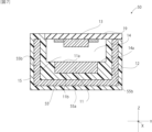
- FIG. 3 is a cross-sectional view of a modification of the current sensor according to the first embodiment.
- FIG. 7 is a cross-sectional view of another modification of the current sensor according to the first embodiment.
- FIG. 3 is a cross-sectional view of a current sensor according to a second embodiment.
- FIG. 7 is a cross-sectional view of a modified example of the current sensor according to the second embodiment.
- FIG. 7 is a cross-sectional view of a current sensor according to a third embodiment.
- FIG. 1 is a perspective view of a current sensor according to an embodiment of the present invention.
- FIG. 2 is a cross-sectional view taken along line AA in FIG. 1 of the current sensor
- FIG. 7 is a cross-sectional view of a current sensor according to a fourth embodiment.
- FIG. 7 is a cross-sectional view of a current sensor according to a fifth embodiment.
- FIG. 7 is a cross-sectional view of a current sensor according to a sixth embodiment.
- FIG. 2 is a cross-sectional view of a conventional current sensor.
- FIG. 1 is a perspective view of a current sensor 10 according to this embodiment.
- the current sensor 10 includes three bus bars 11 integrally molded with a case member 12, a substrate 19 equipped with three magnetic detection sections 13 (see FIG. 3), and three measurement channels. Note that the present invention can also be implemented as a current sensor having one or more measurement channels other than three.
- FIG. 12 is a cross-sectional view of a conventional current sensor 100, showing a cross-section of a portion including a bus bar 101 and a magnetic detection unit 103, which corresponds to the case where the current sensor 100 is cut along the YZ plane along line AA in FIG. ing.
- a resin material is provided on both surfaces of the bus bar 101 in the Z-axis direction, taking into consideration the fluidity of the resin material when insert molding the bus bar 101 into the case member 102. ing.
- the resin material of the case member 102 is formed between the bus bar 101 and the magnetic detection section 103, and the bus bar 101 is exposed in the storage space 104 of the magnetic detection section 103.
- the resin material of the case member 102 is formed between the bus bar 101 and the magnetic detection section 103, and the bus bar 101 is exposed in the storage space 104 of the magnetic detection section 103.
- the thermal conductivity of the resin material forming the case member 102 is higher than that of air.
- the thermal conductivity of polyphenylene sulfide (PPS) is approximately 0.3 W/mK, which is greater than the thermal conductivity of air, 0.0241 W/mK.
- PPS polyphenylene sulfide
- a resin material to which heat generated by the bus bar 101 is more easily transmitted than air is provided between the bus bar 101 and the magnetic detection section 103. Therefore, the heat generated by the bus bar 101 is easily transmitted to a position close to the magnetic detecting section 103 through the resin layer of the resin-based material, and the temperature around the magnetic detecting section 103 is likely to rise.
- FIG. 2 is a cross-sectional view of the current sensor 10 according to the present embodiment taken along the YZ plane along line AA in FIG.
- FIG. 3 is a plan view of the current sensor 10 of FIG. 2.
- the terminals of the magnetic detection section 13 and the substrate 19 are shown. is omitted.
- the current sensor 10 includes a bus bar 11, a case member 12, and a magnetic detection section 13.
- the bus bar 11 is a conductive material formed in a plate shape, and a portion thereof is formed integrally with the case member 12 by insert molding.
- the bus bar 11 is made of, for example, copper, brass, aluminum, or the like, and a current to be measured to be detected flows therethrough.
- the bus bar 11 is provided so that two opposing plate surfaces correspond to the upper and lower sides of the case member 12 (both sides in the Z-axis direction), respectively.
- both end portions of the bus bar 11 that are connection portions with the outside in the X-axis direction do not necessarily have to be line symmetrical with respect to the Y-axis.
- the portion of the bus bar 11 facing the magnetic detection section 13 may be set to have a smaller dimension in the Y-axis direction than other portions.
- the portions of the bus bar 11 other than the portion facing the magnetic detection portion 13 do not have to have a flat plate shape, and may be bent, for example.
- the magnetic detection unit 13 is spaced apart from the bus bar 11 and is arranged at a position facing the bus bar 11.
- the center of the width of the magnetic detection section 13 in the Y-axis direction and the center of the width of the bus bar 11 in the Y-axis direction are arranged so as to overlap.
- the magnetic detection section 13 only needs to be located at a position where it can measure the magnetic field generated when the current to be measured flows through the bus bar 11. For this reason, the entire magnetic detection section 13 may be disposed not at a position overlapping the bus bar 11 but at a shifted position.
- a substrate 19 on which a magnetic detection section 13 is mounted is fixed to a case member 12 into which a bus bar 11 is insert-molded. Therefore, the bus bar 11 and the magnetic detection section 13 can be positioned with high precision.
- a portion of the bus bar 11 is buried in the first surface 14a of the storage space 14.
- the first surface 14a is a part of the surface that defines the storage space 14, and faces the magnetic detection section 13 along the first direction (Z-axis direction). Since the facing surface 11a of the bus bar 11 facing the magnetic detection section 13 is exposed on the first surface 14a, there is air as a low thermal conductivity substance between the bus bar 11 and the magnetic detection section 13. is in contact with the opposing surface 11a.
- the opposing surface 11a of the bus bar 11 in the current sensor 10 is in contact with air, which is a low thermal conductivity material, on its entire surface.
- the influence of heat from the bus bar 11 can be reduced, and the temperature around the magnetic detection section 13 can be kept lower than in the conventional current sensor 100. Therefore, the current to be measured flowing through the bus bar 11 can be increased.
- the resin-based materials include materials made of resin and materials in which fillers and the like are added to resin.
- an opposing surface 11 a facing the magnetic detection section 13 is exposed in the storage space 14 , and an opposite surface 11 b on the opposite side of the opposing surface 11 a is embedded in the case member 12 .
- the entire opposing surface 11a of the bus bar 11 is exposed and the entire opposing surface 11b is buried in the case member 12.
- the opposing surface 11a of the bus bar 11 and the first surface 14a of the storage space 14 form the same plane. .
- FIG. 4 is a sectional view of a modified example of the current sensor.
- the current sensor 20 according to the modification differs from the current sensor 10 in that the opposing surface 11a and the first surface 14a do not form the same plane.
- the current sensor 10 shown in FIG. The distance L2 in the first direction (Z-axis direction) is equal.
- the distance L1 between the facing surface 11a of the bus bar 11 and the magnetic detection section 13 is smaller than the distance L2 between the first surface 14a of the storage space 14 and the magnetic detection section 13.
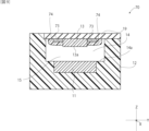
- FIG. 5 is a cross-sectional view of another modification of the current sensor.
- the distance L1 between the facing surface 11a of the bus bar 11 and the magnetic detection section 13 is larger than the distance L2 between the first surface 14a of the storage space 14 and the magnetic detection section 13.
- air acts as a low thermal conductivity substance, and the heat of the bus bar 11 can be suppressed from being transmitted to the magnetic detection section 13.
- FIG. 6 is a cross-sectional view of the current sensor 40 according to this embodiment.
- Current sensor 40 differs from current sensor 10 in the configuration in which magnetic shield 45 is arranged.
- the magnetic shield 45 includes a pair of flat magnetic shields 45A and 45B that are arranged in the Z-axis direction.
- the magnetic detection unit 13 and the bus bar 11 are arranged between the magnetic shield 45A and the magnetic shield 45B in the Z-axis direction.
- the magnetic shield 45A disposed proximal to the bus bar 11 is formed integrally with the case member 12 together with the bus bar 11, and is provided on the side of the bus bar 11 opposite to the side on which the magnetic detection section 13 is disposed.
- the magnetic shield 45B disposed proximal to the magnetic detection section 13 is formed integrally with the cover member 42, and is provided on the side of the magnetic detection section 13 opposite to the side on which the bus bar 11 is disposed.
- the magnetic shields 45A and 45B are made of, for example, a plurality of stacked metal plate bodies of the same shape. Since external magnetic field noise can be blocked by the magnetic shields 45A and 45B, the resistance of the magnetic detection section 13 to external magnetic field noise is improved. However, since only one of the magnetic shields 45A and 45B is effective in blocking external magnetic field noise, only one of the magnetic shields 45A or 45B may be provided instead of a pair.
- FIG. 7 is a cross-sectional view of a modification of the current sensor according to the present embodiment.
- the current sensor 50 according to this modification has a U-shaped cut surface on a YZ plane perpendicular to the extending direction (X-axis direction) of the bus bar 11 so as to surround the bus bar 11 and the magnetic detection section 13. It differs from the current sensor 40 in that it includes a certain magnetic shield 55.
- the magnetic shield 55 includes a base portion 55a disposed on the opposite side of the bus bar 11 from the magnetic detection portion 13, and side wall portions 55b extending along the Z-axis direction from both ends of the base portion 55a. are doing.
- the magnetic shield 55 surrounds the bus bar 11 and the magnetic detection section 13, that is, when viewed along the Z-axis direction, the bus bar 11 and the magnetic detection section 13 overlap the base 55a, and when viewed along the Y-axis direction. At times, the bus bar 11 and the magnetic detection section 13 are arranged so as to overlap the side wall section 55b. Therefore, the magnetic shield 55 can effectively block external magnetic field noise to the bus bar 11 and the magnetic detection section 13, and the resistance of the current sensor 50 to external magnetic field noise is improved.
- FIG. 8 is a cross-sectional view of the current sensor 60 according to this embodiment.
- the current sensor 60 is different from the current sensor 10 in the shape of the bus bar 61 and the configuration in which the magnetic detection section 63 is a differential detection type.
- the current sensor 60 includes a first magnetic detecting section 63A and a second magnetic detecting section 63B as the magnetic detecting section 63, and based on the output of the first magnetic detecting section 63A and the output of the second magnetic detecting section 63B, Magnetism generated from the bus bar 61 can be detected.
- a Hall element or a magnetoresistive element having detection axes oriented in the same or opposite directions in the Z-axis direction is used.
- the bus bar 61 of this embodiment has a cross-sectional shape perpendicular to the extension direction (X-axis direction), and a dimension D1 in the Z-axis direction (first direction) is in the Y-axis direction (second direction) perpendicular to the Z-axis direction. is larger than the dimension D2. That is, the bus bar 61 has a plate-like shape whose width in the Y-axis direction is narrower than its width in the Z-axis direction. Therefore, when the current to be measured flows, as shown using the dashed line in FIG. 8, the component in the Z-axis direction (first direction) is larger than the component in the Y-axis direction (second direction). It produces an elongated elliptical magnetic field with .
- a magnetic field can be formed in which the component in the first direction (Z-axis direction) is large and in the opposite direction.
- a bus bar whose dimension D1 is larger than the dimension D2 dimension D1>dimension D2
- a bus bar whose dimension D1 is smaller than or equal to the dimension D2 dimension D1 ⁇ dimension D2 may be used.
- a first magnetic detecting section 63A and a second magnetic detecting section 63B which exhibit strong sensitivity to a magnetic field in a specific direction (sensitivity direction), are used.
- the first magnetic detection section 63A and the second magnetic detection section 63B are arranged so that their sensitivity directions are substantially parallel.
- the first magnetic detection section 63A and the first magnetic detection section 63A are placed in a position where the direction of the magnetic field due to the current to be measured is almost opposite, and in an attitude where the direction of sensitivity is approximately parallel to the direction of the magnetic field. 2 magnetic detection sections 63B are arranged.
- the vector direction of the magnetic field of the current to be measured at the location where the pair of first magnetic detection section 63A and second magnetic detection section 63B are arranged is opposite, and the difference in the magnetic field as a vector is large.
- a current measurement result is obtained based on the magnetic field as a vector detected by the first magnetic detection section 63A and the second magnetic detection section 63B.
- the first magnetic detecting section 63A and the second magnetic detecting section 63B have the same sensitivity direction
- the first magnetic detecting section 63A and the second magnetic detecting section 63B have two A current measurement result is obtained based on the difference between the two detection signals.
- the current is measured based on the sum of two detection signals in the first magnetic detecting section 63A and the second magnetic detecting section 63B. Get results.
- External magnetic field noise common to the first magnetic detecting section 63A and the second magnetic detecting section 63B is detected by detecting the magnetic field of the bus bar 61 based on the outputs of the first magnetic detecting section 63A and the second magnetic detecting section 63B. can remove the influence of Therefore, the current sensor 60 can accurately detect the induced magnetic field of the bus bar 61.
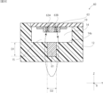
- FIG. 9 is a cross-sectional view of the current sensor 70 according to this embodiment.
- the current sensor 70 has a configuration in which the magnetic detection section 13 includes an output terminal section 73, the output terminal section 73 is held on the substrate 19, and the output terminal section 73 is sealed with a sealant 74. It is different from 10. By potting and sealing the output terminal portion 73 with the sealant 74, discharge from the bus bar 11 to the output terminal portion 73 is less likely to occur, and the voltage resistance of the current sensor 70 is improved.
- the sealant 74 is provided so as to cover the output terminal section (electrode terminal) 73 and not cover the opposing surface 13a of the magnetic detection section 13 that faces the bus bar 11. Therefore, it is possible to reduce the heat of the bus bar 11 that is transmitted to the magnetic detection section 13 via the sealant 74, which has higher thermal conductivity than the air in the storage space 14. Therefore, the temperature of the magnetic detection section 13 is prevented from increasing due to the heat of the bus bar 11.
- FIG. 10 is a cross-sectional view of the current sensor 80 according to this embodiment.
- the current sensor 80 includes a cover member 82 that covers the storage space 14 , the magnetic detection section 13 includes an output terminal section 83 , the output terminal section 83 is held on the substrate 19 , and the substrate 19 is held on the cover member 82 .
- a holding member 84 is provided.
- FIG. 11 is a cross-sectional view of the current sensor 90 according to this embodiment.
- the current sensor 90 differs from the current sensor 10 in that a low thermal conductivity material 95 other than the air layer 15 (see FIG. 2) is provided in contact with the opposing surface 11a of the bus bar 11.
- the temperature rise in the magnetic detecting section 13 due to the heat of the bus bar 11 being transmitted to the magnetic detecting section 13 is reduced. be able to.
- Examples of the low thermal conductivity material 95 include porous ceramic.
- the thermal conductivity of porous ceramics depends on the type, but some porous ceramics have a thermal conductivity of about 0.003 W/mK, for example. Although this value is slightly higher than the thermal conductivity of air, it is sufficiently lower than the thermal conductivity of resin-based materials such as polyphenylene sulfide. Therefore, by providing the low thermal conductivity material 95, the heat transmitted from the bus bar 11 to the magnetic detection section 13 can be reduced, similar to the layer of air.
- the low thermal conductivity material 95 does not need to be provided to cover the entire opposing surface 11a of the bus bar 11 and the first surface 14a of the storage space 14, as shown in FIG.
- the low thermal conductivity material 95 may be provided so as to cover only the opposing surface 11a.
- a configuration may be adopted in which a part of the opposing surface 11a of the bus bar 11 is covered with the low thermal conductivity material 95, and the other area is covered with the air layer 15.
- a simulation was performed on how easily heat is transmitted from the bus bar 11 to the magnetic detection section 13. Further, for the conventional current sensor 100 shown in FIG. 12, a simulation was also conducted to determine how easily heat is transmitted from the bus bar 101 to the magnetic detection section 103. In these simulations, the continuously applied current to be measured was 200 A, and the temperatures of the magnetic detection units 13 and 103 were determined when the temperature of the bus bars 11 and 101 reached 146°C.
- the current sensor 10 was evaluated in which the entire surface of the facing surface 11a of the bus bar 11 was exposed, and the distance L1 and distance L2 in the Z-axis direction between the facing surface 11a of the bus bar 11 and the magnetic detection section 13 were 4.2 mm. did.
- the conventional current sensor 100 differs from the current sensor 10 only in that the entire opposing surface 101a of the bus bar 101 is covered with a resin material with a thickness of 1.2 mm, and the distance L1 is 3.0 mm and the distance L2 is 1. .2 mm was evaluated.
- the resin material constituting the case member 12 and the case member 102 was polyphenylene sulfide (PPS).
- the temperature of the magnetic detection unit 13 of the current sensor 10 was 121.8°C, while the temperature of the magnetic detection unit 103 of the current sensor 100 was 129.0°C.
- the present invention in which the resin material is removed from the opposing surface 11a of the bus bar 11 to expose the opposing surface 11a makes it possible to reduce the temperature rise in the magnetic detection section 13 due to the influence of heat from the bus bar 11. . From this simulation result, it can be seen that the current sensor 10 of the present invention can use the magnetic detection section 13 whose heat resistance temperature is 125° C., which cannot be used with the conventional current sensor 100.
- the present invention is useful as a current sensor equipped with a bus bar through which a large current flows as the current to be measured.
Landscapes
- Physics & Mathematics (AREA)
- General Physics & Mathematics (AREA)
- Condensed Matter Physics & Semiconductors (AREA)
- Measuring Instrument Details And Bridges, And Automatic Balancing Devices (AREA)
Priority Applications (5)
| Application Number | Priority Date | Filing Date | Title |
|---|---|---|---|
| JP2024540246A JP7727119B2 (ja) | 2022-08-10 | 2023-02-22 | 電流センサ |
| CN202380054250.0A CN119563113A (zh) | 2022-08-10 | 2023-02-22 | 电流传感器 |
| KR1020257001436A KR102858944B1 (ko) | 2022-08-10 | 2023-02-22 | 전류 센서 |
| DE112023003407.9T DE112023003407T5 (de) | 2022-08-10 | 2023-02-22 | Stromsensor |
| US19/014,378 US20250147075A1 (en) | 2022-08-10 | 2025-01-09 | Current Sensor |
Applications Claiming Priority (2)
| Application Number | Priority Date | Filing Date | Title |
|---|---|---|---|
| JP2022-128294 | 2022-08-10 | ||
| JP2022128294 | 2022-08-10 |
Related Child Applications (1)
| Application Number | Title | Priority Date | Filing Date |
|---|---|---|---|
| US19/014,378 Continuation US20250147075A1 (en) | 2022-08-10 | 2025-01-09 | Current Sensor |
Publications (1)
| Publication Number | Publication Date |
|---|---|
| WO2024034164A1 true WO2024034164A1 (ja) | 2024-02-15 |
Family
ID=89851328
Family Applications (1)
| Application Number | Title | Priority Date | Filing Date |
|---|---|---|---|
| PCT/JP2023/006396 Ceased WO2024034164A1 (ja) | 2022-08-10 | 2023-02-22 | 電流センサ |
Country Status (6)
| Country | Link |
|---|---|
| US (1) | US20250147075A1 (https=) |
| JP (1) | JP7727119B2 (https=) |
| KR (1) | KR102858944B1 (https=) |
| CN (1) | CN119563113A (https=) |
| DE (1) | DE112023003407T5 (https=) |
| WO (1) | WO2024034164A1 (https=) |
Cited By (1)
| Publication number | Priority date | Publication date | Assignee | Title |
|---|---|---|---|---|
| WO2025263082A1 (ja) * | 2024-06-20 | 2025-12-26 | アルプスアルパイン株式会社 | 電流センサ |
Families Citing this family (1)
| Publication number | Priority date | Publication date | Assignee | Title |
|---|---|---|---|---|
| JP2024113292A (ja) * | 2023-02-09 | 2024-08-22 | アルプスアルパイン株式会社 | 電流計測装置および電流センサ |
Citations (7)
| Publication number | Priority date | Publication date | Assignee | Title |
|---|---|---|---|---|
| US20120081110A1 (en) * | 2010-10-01 | 2012-04-05 | Robert Racz | Current sensor |
| JP2016148620A (ja) * | 2015-02-13 | 2016-08-18 | 株式会社フジクラ | 電流センサ |
| JP2017040591A (ja) * | 2015-08-20 | 2017-02-23 | トヨタ自動車株式会社 | 電流センサ |
| JP2018036111A (ja) * | 2016-08-30 | 2018-03-08 | 株式会社Soken | 電流計測装置 |
| JP2019105613A (ja) * | 2017-12-14 | 2019-06-27 | 日立金属株式会社 | 電流センサ |
| JP2020128961A (ja) * | 2019-02-12 | 2020-08-27 | 日立金属株式会社 | 電流センサ |
| WO2021095566A1 (ja) * | 2019-11-15 | 2021-05-20 | アルプスアルパイン株式会社 | 電流検出装置 |
Family Cites Families (6)
| Publication number | Priority date | Publication date | Assignee | Title |
|---|---|---|---|---|
| JP5086169B2 (ja) * | 2008-05-09 | 2012-11-28 | 株式会社東海理化電機製作所 | 電流センサ及び電流センサの製造方法 |
| JP5586707B2 (ja) | 2010-12-07 | 2014-09-10 | 三菱電機株式会社 | 電力変換回路内蔵モーター、この電力変換回路内蔵モーターを搭載した流体ポンプ、この流体ポンプを搭載した空気調和機、給湯器、電力変換回路内蔵モーターを搭載した機器 |
| JP6477089B2 (ja) * | 2014-05-23 | 2019-03-06 | 株式会社デンソー | 電流センサ付バスバーモジュール |
| WO2016190087A1 (ja) | 2015-05-22 | 2016-12-01 | アルプス・グリーンデバイス株式会社 | 電流センサ |
| JP6402089B2 (ja) | 2015-12-02 | 2018-10-10 | アルプス電気株式会社 | 電流センサ |
| EP3690450A1 (en) * | 2019-01-30 | 2020-08-05 | LEM International SA | Current transducer with magnetic field detector module |
-
2023
- 2023-02-22 CN CN202380054250.0A patent/CN119563113A/zh active Pending
- 2023-02-22 WO PCT/JP2023/006396 patent/WO2024034164A1/ja not_active Ceased
- 2023-02-22 DE DE112023003407.9T patent/DE112023003407T5/de active Pending
- 2023-02-22 KR KR1020257001436A patent/KR102858944B1/ko active Active
- 2023-02-22 JP JP2024540246A patent/JP7727119B2/ja active Active
-
2025
- 2025-01-09 US US19/014,378 patent/US20250147075A1/en active Pending
Patent Citations (7)
| Publication number | Priority date | Publication date | Assignee | Title |
|---|---|---|---|---|
| US20120081110A1 (en) * | 2010-10-01 | 2012-04-05 | Robert Racz | Current sensor |
| JP2016148620A (ja) * | 2015-02-13 | 2016-08-18 | 株式会社フジクラ | 電流センサ |
| JP2017040591A (ja) * | 2015-08-20 | 2017-02-23 | トヨタ自動車株式会社 | 電流センサ |
| JP2018036111A (ja) * | 2016-08-30 | 2018-03-08 | 株式会社Soken | 電流計測装置 |
| JP2019105613A (ja) * | 2017-12-14 | 2019-06-27 | 日立金属株式会社 | 電流センサ |
| JP2020128961A (ja) * | 2019-02-12 | 2020-08-27 | 日立金属株式会社 | 電流センサ |
| WO2021095566A1 (ja) * | 2019-11-15 | 2021-05-20 | アルプスアルパイン株式会社 | 電流検出装置 |
Cited By (1)
| Publication number | Priority date | Publication date | Assignee | Title |
|---|---|---|---|---|
| WO2025263082A1 (ja) * | 2024-06-20 | 2025-12-26 | アルプスアルパイン株式会社 | 電流センサ |
Also Published As
| Publication number | Publication date |
|---|---|
| US20250147075A1 (en) | 2025-05-08 |
| KR20250024990A (ko) | 2025-02-20 |
| JP7727119B2 (ja) | 2025-08-20 |
| JPWO2024034164A1 (https=) | 2024-02-15 |
| KR102858944B1 (ko) | 2025-09-11 |
| DE112023003407T5 (de) | 2025-05-22 |
| CN119563113A (zh) | 2025-03-04 |
Similar Documents
| Publication | Publication Date | Title |
|---|---|---|
| US20250147075A1 (en) | Current Sensor | |
| US10746821B2 (en) | Current sensor | |
| CN113295907B (zh) | 电流传感器 | |
| US9164132B2 (en) | Current sensor | |
| US11555834B2 (en) | Magnetic sensor and method of manufacturing such, magnetic control device, and current sensor design method | |
| US20180321281A1 (en) | Current sensor | |
| US20140232376A1 (en) | Current sensor | |
| US7528593B2 (en) | Current measuring device | |
| US9335349B2 (en) | Current sensor | |
| US20250147076A1 (en) | Current Sensor And Current Control System | |
| JPWO2024034164A5 (https=) | ||
| US12504447B2 (en) | Current sensor | |
| JP2018081024A (ja) | 電流センサ | |
| JP2012145387A (ja) | 電流センサ | |
| US20250216424A1 (en) | Current Sensor | |
| WO2025120986A1 (ja) | 電流センサ | |
| WO2025258208A1 (ja) | 電流センサ、パワーモジュールおよび電流センサの製造方法 | |
| WO2024095585A1 (ja) | 電流センサ | |
| WO2023074083A1 (ja) | 電流センサ | |
| JP2024104947A (ja) | 電流センサ | |
| JP2020165942A (ja) | 半導体装置 | |
| JP2012145532A (ja) | 電流センサ |
Legal Events
| Date | Code | Title | Description |
|---|---|---|---|
| 121 | Ep: the epo has been informed by wipo that ep was designated in this application |
Ref document number: 23848588 Country of ref document: EP Kind code of ref document: A1 |
|
| WWE | Wipo information: entry into national phase |
Ref document number: 2024540246 Country of ref document: JP |
|
| ENP | Entry into the national phase |
Ref document number: 20257001436 Country of ref document: KR Kind code of ref document: A |
|
| WWE | Wipo information: entry into national phase |
Ref document number: 1020257001436 Country of ref document: KR |
|
| WWE | Wipo information: entry into national phase |
Ref document number: 202380054250.0 Country of ref document: CN |
|
| WWP | Wipo information: published in national office |
Ref document number: 1020257001436 Country of ref document: KR |
|
| WWE | Wipo information: entry into national phase |
Ref document number: 202547019115 Country of ref document: IN |
|
| WWP | Wipo information: published in national office |
Ref document number: 202380054250.0 Country of ref document: CN |
|
| WWE | Wipo information: entry into national phase |
Ref document number: 112023003407 Country of ref document: DE |
|
| WWP | Wipo information: published in national office |
Ref document number: 202547019115 Country of ref document: IN |
|
| WWP | Wipo information: published in national office |
Ref document number: 112023003407 Country of ref document: DE |
|
| 122 | Ep: pct application non-entry in european phase |
Ref document number: 23848588 Country of ref document: EP Kind code of ref document: A1 |