WO2024029592A1 - 光ファイバ着色心線及びその製造方法 - Google Patents
光ファイバ着色心線及びその製造方法 Download PDFInfo
- Publication number
- WO2024029592A1 WO2024029592A1 PCT/JP2023/028382 JP2023028382W WO2024029592A1 WO 2024029592 A1 WO2024029592 A1 WO 2024029592A1 JP 2023028382 W JP2023028382 W JP 2023028382W WO 2024029592 A1 WO2024029592 A1 WO 2024029592A1
- Authority
- WO
- WIPO (PCT)
- Prior art keywords
- optical fiber
- modulus
- primary layer
- curable resin
- young
- Prior art date
- Legal status (The legal status is an assumption and is not a legal conclusion. Google has not performed a legal analysis and makes no representation as to the accuracy of the status listed.)
- Ceased
Links
Images

Classifications
-
- C—CHEMISTRY; METALLURGY
- C03—GLASS; MINERAL OR SLAG WOOL
- C03C—CHEMICAL COMPOSITION OF GLASSES, GLAZES OR VITREOUS ENAMELS; SURFACE TREATMENT OF GLASS; SURFACE TREATMENT OF FIBRES OR FILAMENTS MADE FROM GLASS, MINERALS OR SLAGS; JOINING GLASS TO GLASS OR OTHER MATERIALS
- C03C25/00—Surface treatment of fibres or filaments made from glass, minerals or slags
- C03C25/10—Coating
- C03C25/104—Coating to obtain optical fibres
- C03C25/1065—Multiple coatings
-
- C—CHEMISTRY; METALLURGY
- C03—GLASS; MINERAL OR SLAG WOOL
- C03C—CHEMICAL COMPOSITION OF GLASSES, GLAZES OR VITREOUS ENAMELS; SURFACE TREATMENT OF GLASS; SURFACE TREATMENT OF FIBRES OR FILAMENTS MADE FROM GLASS, MINERALS OR SLAGS; JOINING GLASS TO GLASS OR OTHER MATERIALS
- C03C25/00—Surface treatment of fibres or filaments made from glass, minerals or slags
- C03C25/10—Coating
- C03C25/104—Coating to obtain optical fibres
- C03C25/105—Organic claddings
-
- G—PHYSICS
- G02—OPTICS
- G02B—OPTICAL ELEMENTS, SYSTEMS OR APPARATUS
- G02B6/00—Light guides; Structural details of arrangements comprising light guides and other optical elements, e.g. couplings
- G02B6/44—Mechanical structures for providing tensile strength and external protection for fibres, e.g. optical transmission cables
-
- C—CHEMISTRY; METALLURGY
- C03—GLASS; MINERAL OR SLAG WOOL
- C03C—CHEMICAL COMPOSITION OF GLASSES, GLAZES OR VITREOUS ENAMELS; SURFACE TREATMENT OF GLASS; SURFACE TREATMENT OF FIBRES OR FILAMENTS MADE FROM GLASS, MINERALS OR SLAGS; JOINING GLASS TO GLASS OR OTHER MATERIALS
- C03C2218/00—Methods for coating glass
- C03C2218/30—Aspects of methods for coating glass not covered above
- C03C2218/32—After-treatment
Definitions
- the present invention relates to a colored optical fiber and a method for manufacturing the same.
- a primary layer that covers the bare optical fiber, a secondary layer that covers the primary layer, and a colored layer that covers the secondary layer are each formed using an ultraviolet curable resin to have a desired Young's modulus to produce a colored optical fiber.
- An ultraviolet curable resin to have a desired Young's modulus to produce a colored optical fiber.
- Patent Document 1 A technique is known (Patent Document 1). When the Young's modulus of the primary layer is set low, it buffers the external force applied to the bare optical fiber and suppresses optical transmission loss (hereinafter referred to as "microbend loss") due to minute deformation of the bare optical fiber. be able to.
- the saturated Young's modulus which is the maximum Young's modulus that can be expressed by the ultraviolet curable resin constituting the primary layer, to be low.
- the saturated Young's modulus it is generally necessary to change the composition of the monomers and oligomers that constitute most of the ultraviolet curable resin, and it is necessary to change the resin composition significantly.
- additives are generally added to the ultraviolet curable resin used for coating optical fibers.
- additives include silane coupling agents that improve the adhesion between the glass and the primary layer. It is known that when a mercapto group-containing silane coupling agent is used, the mercapto group acts as a polymerization inhibitor and the curability of the coating resin decreases (Patent Document 4).
- the Young's modulus of the primary layer covering the bare optical fiber In order to improve the optical transmission capability of an optical fiber by reducing microbend loss, it is necessary to set the Young's modulus of the primary layer covering the bare optical fiber to a low value as described above. However, if the resin is not sufficiently cured and reactive groups that can participate in curing remain in the resin, exposure to ultraviolet irradiation or light containing ultraviolet rays during the coloring process, tape forming process, etc. after optical fiber manufacturing may Exposure of the primary layer may cause an unexpected increase in Young's modulus.
- the saturated Young's modulus of the resin is determined by the monomer, oligomer, etc. that constitutes the majority of the resin. Therefore, it is necessary to significantly change the resin composition in order to achieve a lower Young's modulus.
- the mercapto group-containing silane coupling agent described in Patent Document 4 as an additive that improves the adhesion between the glass and the primary layer can sufficiently lower the Young's modulus of the primary layer even if the curability decreases. It cannot be planned.
- an object of the present invention is to reduce the Young's modulus of a primary layer to a desired Young's modulus without major changes in the resin composition, and to suppress or prevent an increase in the Young's modulus.
- An object of the present invention is to provide a colored optical fiber and a method for manufacturing the same.
- the primary layer is formed of a bare optical fiber, a first ultraviolet curable resin that covers the bare optical fiber, and a second ultraviolet curable resin that covers the primary layer.
- a secondary layer having a carbon-sulfur bond and containing sulfur atoms of 0.03 wt% or more and 0.65 wt% or less;
- a colored optical fiber core characterized in that the amount of increase in Young's modulus is 0.09 MPa or less.
- a step of drawing a bare optical fiber from an optical fiber base material and a step of applying a first ultraviolet curable resin around the bare optical fiber to form a primary layer.
- a step of applying a second ultraviolet curable resin around the primary layer to form a secondary layer the primary layer has a carbon-sulfur bond and contains 0.03 wt% or more of sulfur atoms and 0.65 wt% of sulfur atoms;
- a method for manufacturing a colored optical fiber characterized in that the amount of increase in Young's modulus of the primary layer due to additional ultraviolet irradiation of the primary layer is 0.09 MPa or less.
- the Young's modulus of the primary layer can be reduced to a desired Young's modulus and an increase in the Young's modulus can be suppressed or prevented without major changes in the resin composition.
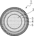
- FIG. 1 is a cross-sectional view of a colored optical fiber according to an embodiment.
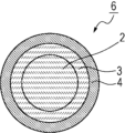
- FIG. 1 is a cross-sectional view of an optical fiber according to an embodiment. It is a schematic diagram showing a part of manufacturing equipment used for a manufacturing method of a colored optical fiber core wire concerning one embodiment. It is a schematic diagram which shows the other part of the manufacturing apparatus used for the manufacturing method of the colored optical fiber core wire based on one Embodiment.
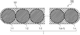
- 1 is a cross-sectional view of an example optical fiber ribbon according to one embodiment.
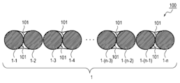
- FIG. FIG. 3 is a cross-sectional view of another example of an optical fiber ribbon according to one embodiment.
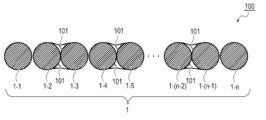
- FIG. 3 is a cross-sectional view of another example of an optical fiber ribbon according to one embodiment.
- FIG. 1 is a cross-sectional view of a colored optical fiber according to an embodiment.
- FIG. 1 is a cross-sectional view of an optical fiber according to an embodiment. It is a schematic diagram showing a part of manufacturing equipment used for a manufacturing method of
- FIG. 1 is a schematic diagram of a ribbon forming apparatus used in a method for manufacturing an optical fiber ribbon according to an embodiment.
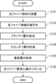
- 1 is a flowchart of a method for manufacturing a colored optical fiber and an optical fiber ribbon according to one embodiment.
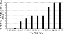
- FIG. 2 is a graph diagram showing the relationship between the difference in Young's modulus of the primary layer of a plurality of colored optical fiber cores and the ratio at which the microbend loss difference is 0.05 dB/km or more.
- FIG. 1A is a cross-sectional view of a colored optical fiber 1 according to the present embodiment.
- the colored optical fiber 1 includes a bare optical fiber 2, a primary layer 3 coated on the outer periphery of the bare optical fiber 2, a secondary layer 4 coated on the outer periphery of the primary layer 3, and a coated outer periphery of the secondary layer 4. and a colored layer 5 coated on the surface.
- the bare optical fiber 2 is covered with three coating layers: a primary layer 3, a secondary layer 4, and a colored layer 5.
- FIG. 1B is a cross-sectional view of the optical fiber 6 according to this embodiment.
- the optical fiber wire 6 is a fiber in a state before the colored layer 5 is formed.
- the bare optical fiber 2 is made of, for example, quartz glass, and transmits light.
- the primary layer 3, the secondary layer 4, and the colored layer 5 are each formed by curing an ultraviolet curable resin by irradiating ultraviolet rays.
- the ultraviolet curable resin is not particularly limited as long as it can be polymerized by irradiation with ultraviolet rays.
- the ultraviolet curable resin is one that can be polymerized by, for example, photoradical polymerization.
- UV-curable resins include, for example, urethane (meth)acrylates such as polyether-based urethane (meth)acrylates and polyester-based urethane (meth)acrylates, epoxy (meth)acrylates, and polyester (meth)acrylates that are polymerized and cured by ultraviolet light. It is an ultraviolet curable resin having a polymerizable unsaturated group such as an ethylenically unsaturated group that hardens, and preferably has at least two polymerizable unsaturated groups.
- Examples of the polymerizable unsaturated group in the ultraviolet curable resin include groups having an unsaturated double bond such as a vinyl group, allyl group, acryloyl group, and methacryloyl group, and groups having an unsaturated triple bond such as a propargyl group. Can be mentioned. Among these, acryloyl groups and methacryloyl groups are preferred in terms of polymerizability.
- the ultraviolet curable resin may be a monomer, oligomer, or polymer that initiates polymerization and cures upon irradiation with ultraviolet rays, but is preferably an oligomer.
- the oligomer is a polymer having a degree of polymerization of 2 to 100.
- (meth)acrylate means one or both of acrylate and methacrylate.
- the ultraviolet curable resin contains any photopolymerization initiator (hereinafter referred to as "photoinitiator”) that has sensitivity in the ultraviolet region.
- Polyether-based urethane (meth)acrylate refers to a polyether segment, (meth)acrylate, and urethane bond, such as a reaction product of a polyol having a polyether skeleton, an organic polyisocyanate compound, and a hydroxyalkyl (meth)acrylate. It is a compound that has
- polyester-based urethane (meth)acrylate is a reaction product of a polyol having a polyester skeleton, an organic polyisocyanate compound, and a hydroxyalkyl (meth)acrylate, and has a polyester segment, (meth)acrylate, and urethane bond. It is a compound.
- the UV-curable resin may contain, for example, a diluent monomer, a photosensitizer, a UV absorber, an antioxidant, a silane coupling agent, a chain transfer agent, and various additives.
- a diluent monomer monofunctional (meth)acrylate or polyfunctional (meth)acrylate is used.
- the diluent monomer means a monomer for diluting the ultraviolet curable resin.
- the primary layer 3 is a soft layer and has a function of buffering external force applied to the bare optical fiber 2. There is a possibility that there is still some room left for curing in the primary layer 3 when the optical fiber 6 is formed, but when it is cured until there is no room left, the Young's modulus of the primary layer 3 is Maximum. In this embodiment, the maximum Young's modulus that the primary layer 3 of the optical fiber 6 can exhibit is defined as a "saturated Young's modulus.”
- the ultraviolet curable resin constituting the primary layer 3 may contain a mercapto group-containing compound in order to configure the primary layer 3 to have a carbon-sulfur bond as described below.
- a mercapto group-containing compound is a compound having at least one mercapto group in one molecule.
- the mercapto group-containing compound has the effect of reacting with a polymerizable compound such as urethane (meth)acrylate contained in the ultraviolet curable resin using a mercapto group to terminate the polymerization of the polymerizable compound.
- Mercapto group-containing compounds are not particularly limited, but include (3-mercaptopropyl)trimethoxysilane, isooctyl 3-mercaptopropionate, and 1-pentanethiol used in the examples described below, as well as ethyl mercaptan, 1-Butanethiol, 1-heptanethiol, 1-undecanethiol, 4-hydroxybenzenethiol, (2-mercaptoethyl)pyrazine, 2,3-butanedithiol, 3-methyl-2-butanethiol, 3-mercapto-1 , 2,4-triazole, 1,3,4-thiadiazole-2-thiol, isobutylmercaptan, 4-methoxy- ⁇ -toluenethiol, 4,4'-biphenyldithiol, trimethylsilylmethanethiol, 1,4-butanedithiol, Examples include 1,8-octanedithiol
- Irradiation of ultraviolet rays is performed at appropriate illumination intensity and irradiation amount using, for example, a mercury lamp or UV-LED.
- the saturated Young's modulus changes depending on the optical fiber manufacturing conditions (e.g., linear speed, UV irradiation intensity, UV light source type, resin coating temperature, etc.), and is not uniquely determined by the UV curable resin used. I don't get it.
- the secondary layer 4 is preferably a hard layer having a Young's modulus of 500 MPa or more, and has a function of protecting the bare optical fiber 2 and the primary layer 3 from external force.
- the colored layer 5 is the outermost layer of the colored optical fiber 1 and has the function of protecting the bare optical fiber 2, primary layer 3, and secondary layer 4 from external forces.
- the colored layer 5 is colored with a coloring agent mixed with a pigment, a lubricant, etc. in order to identify the colored optical fiber core 1 .
- Examples of the color include white, black, gray, purple, blue, light blue, green, brown, yellow, orange, pink, and red.
- the diameter of the bare optical fiber 2 may be, for example, 80 ⁇ m or more and 150 ⁇ m or less, preferably 124 ⁇ m or more and 126 ⁇ m or less.
- the thickness of the primary layer 3 may preferably be 5 ⁇ m or more and 60 ⁇ m or less.
- the thickness of the secondary layer 4 may preferably be 5 ⁇ m or more and 60 ⁇ m or less.
- the thickness of the colored layer 5 may preferably be approximately several ⁇ m.
- the diameter of the optical fiber 6 is determined by the sum of the diameter of the bare optical fiber 2, the length twice the thickness of the primary layer 3, and the length twice the thickness of the secondary layer 4. It can be done. Therefore, the diameter of the bare optical fiber 2, the thickness of the primary layer 3, and the thickness of the secondary layer 4 can be selected so that the diameter of the optical fiber 6 is, for example, about 190 to 250 ⁇ m.
- the colored layer 5 is formed separately from the secondary layer 4, but it is also possible to color the secondary layer 4 without forming the colored layer 5 and use the secondary layer 4 as a colored layer. can also be made to work.
- the secondary layer 4 can be colored by incorporating a coloring agent similar to the coloring agent that colors the colored layer 5 into the ultraviolet curable resin constituting the secondary layer 4 .
- an effective core cross-sectional area (effective core cross-sectional area) Aeff can be cited as an index representing the ease with which microbend loss occurs in an optical fiber.
- the effective core cross-sectional area Aeff is expressed by the following equation (1).
- the effective core cross-sectional area Aeff is a value at a wavelength of 1550 nm
- MFD is a mode field diameter ( ⁇ m)
- k is a constant.
- the effective core cross-sectional area Aeff represents the area of a portion of the cross section perpendicular to the axis of the bare optical fiber 2 through which light having a predetermined intensity passes.
- Aeff is an index of microbend sensitivity, and the larger Aeff is, the higher the microbend sensitivity is (generally, it is said that if Aeff>100 ⁇ m 2 , the microbend sensitivity is high).
- Aeff is 130 ⁇ m 2 or more and 150 ⁇ m 2 or less, the optical fiber has high microbend sensitivity without any problem.
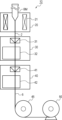
- FIG. 2A is a schematic diagram showing a part of the manufacturing apparatus 10 used in the method for manufacturing the colored optical fiber core 1 according to the present embodiment.
- the manufacturing apparatus 10 includes a heating device 20, a primary layer coating device 30, a secondary layer coating device 40, a guide roller 45, and a first winding device 50.
- the optical fiber base material BM is made of, for example, quartz-based glass, and is manufactured by a well-known method such as a VAD method, an OVD method, or an MCVD method.
- the heating device 20 has a heater 21.
- the heater 21 may be any heat source such as a tape heater, ribbon heater, rubber heater, oven heater, ceramic heater, or halogen heater.
- the end of the optical fiber preform BM is heated and melted by a heater 21 disposed around the optical fiber preform BM, and is drawn into a bare optical fiber 2.
- a primary layer coating device 30 is provided below the heating device 20.
- the primary layer coating device 30 includes a resin coating device 31 and an ultraviolet irradiation device 32.
- the resin coating device 31 holds an ultraviolet curable resin (hereinafter referred to as "first ultraviolet curable resin") which is a coating material for forming the primary layer 3 .
- first ultraviolet curable resin an ultraviolet curable resin
- the bare optical fiber 2 drawn out from the optical fiber base material BM is coated with a first ultraviolet curable resin by a resin coating device 31 .
- the ultraviolet irradiation device 32 includes any ultraviolet light source such as a metal halide lamp, a mercury lamp, or a UV-LED.
- a first ultraviolet curable resin is applied to the bare optical fiber 2 by a resin coating device 31, the bare optical fiber 2 enters an ultraviolet irradiation device 32, and the first ultraviolet curable resin is irradiated with ultraviolet rays. As a result, the first ultraviolet curable resin is cured, and the primary layer 3 is formed.
- a secondary layer coating device 40 is provided below the primary layer coating device 30.
- the secondary layer coating device 40 includes a resin coating device 41 and an ultraviolet irradiation device 42.
- the resin coating device 41 holds an ultraviolet curable resin (hereinafter referred to as "second ultraviolet curable resin") which is a coating material for forming the secondary layer 4.
- second ultraviolet curable resin is applied to the primary layer 3 by a resin coating device 41 .
- An ultraviolet irradiation device 42 is provided below the resin coating device 41.
- the ultraviolet irradiation device 42 may be configured similarly to the ultraviolet irradiation device 32.
- the bare optical fiber 2 whose primary layer 3 is coated with the second ultraviolet curable resin enters the ultraviolet irradiation device 42, and the second ultraviolet curable resin is irradiated with ultraviolet rays. As a result, the second ultraviolet curable resin is cured, and the secondary layer 4 is formed.
- an optical fiber 6 is formed.
- the resin coating device 31 may be configured to hold the first ultraviolet curable resin and the second ultraviolet curable resin separately. In this case, the resin coating device 31 applies the first ultraviolet curable resin to the bare optical fiber 2, and then applies the second ultraviolet curable resin onto the first ultraviolet curable resin. Further, in this case, the ultraviolet irradiation device 32 irradiates the first ultraviolet curable resin and the second ultraviolet curable resin coated on the bare optical fiber 2 with ultraviolet rays. As a result, a primary layer 3 and a secondary layer 4 are formed. In this case, the manufacturing apparatus 10 does not necessarily need to have the secondary layer coating apparatus 40.
- a guide roller 45 and a first winding device 50 are provided below the secondary layer coating device 40.
- the manufactured optical fiber strand 6 is guided by a guide roller 45 and wound up by a first winding device 50 .
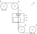
- FIG. 2B is a schematic diagram showing other parts of the manufacturing apparatus 10 used in the method for manufacturing the colored optical fiber core 1 according to the present embodiment.
- the manufacturing apparatus 10 includes a wire holding device 55, a guide roller 56, a colored layer coating device 60, a guide roller 65, and a second winding device 70.
- the manufacturing apparatus 10 manufactures the colored optical fiber core 1 from the optical fiber strands 6 manufactured by the plurality of apparatuses shown in FIG. 2A.
- the wire holding device 55 holds the manufactured optical fiber wire 6 in a wound state. Note that in FIG. 2B, the wire holding device 55 is a separate device from the first winding device 50, but the first winding device 50 may also serve as the wire holding device 55.
- a colored layer coating device 60 is provided below the strand holding device 55.
- the optical fiber strand 6 pulled out from the strand holding device 55 is guided by a guide roller 56 provided between the strand holding device 55 and the colored layer coating device 60, and is transported into the colored layer coating device 60. be done.
- the colored layer coating device 60 has a resin coating device 61 and an ultraviolet irradiation device 62.
- the resin coating device 61 holds an ultraviolet curable resin (hereinafter referred to as "third ultraviolet curable resin") which is a coating material for forming the colored layer 5.
- a third ultraviolet curable resin is applied to the optical fiber strand 6 by a resin coating device 61.
- An ultraviolet irradiation device 62 is provided below the resin coating device 61.
- the ultraviolet irradiation device 62 may be configured similarly to the ultraviolet irradiation devices 32 and 42.
- the optical fiber 6 whose outer periphery of the secondary layer 4 is coated with the third ultraviolet curable resin enters the ultraviolet irradiation device 62, and the third ultraviolet ray curable resin and the optical fiber 6 are irradiated with ultraviolet rays. As a result, the third ultraviolet curable resin is cured, and the colored layer 5 is formed.
- a colored optical fiber 1 is formed by coating the bare optical fiber 2 with the primary layer 3, the secondary layer 4, and the colored layer 5.
- the colored optical fiber core wire 1 after manufacturing is guided by a guide roller 65 provided below the colored layer coating device 60 and wound up by the second winding device 70 .
- the secondary layer 4 is colored without forming the colored layer 5 so that the secondary layer 4 also functions as a colored layer
- the above-mentioned steps by other parts shown in FIG. 2B of the manufacturing apparatus 10 can be omitted.
- the second ultraviolet curable resin applied by the resin coating device 41 is colored by adding a coloring agent, and the colored second ultraviolet curable resin can be applied around the primary layer 3.
- the secondary layer 4 colored with the colorant can be formed.
- FIG. 3A is a cross-sectional view of an example of the optical fiber ribbon 100 according to the present embodiment.
- the optical fiber ribbon 100 is constructed by bundling n (n is a natural number of 2 or more) colored optical fibers 1-1 to 1-n into a strip with an adhesive layer 101 interposed therebetween.
- n is a natural number of 2 or more
- the optical fiber ribbon 100 is not limited to having a structure in which all of the colored optical fibers 1-1 to 1-n are bundled into one as shown in FIG. 3A, but as shown in FIG. 3B and It may have an intermittent bonding type structure shown in FIG. 3C.
- two or more colored optical fiber cores 1 consecutively arranged in the width direction are bundled into a single strip via an adhesive layer 101.
- 3B and 3C show a structure in which two colored optical fibers 1 arranged adjacent to each other in the width direction are bundled into one belt shape with an adhesive layer 101 interposed therebetween.
- each colored optical fiber 1 may be bundled with other colored optical fibers 1, or as shown in FIG. 3C, a plurality of colored optical fibers 1 may be bundled together. Some of them may not be bundled with other colored optical fibers 1.
- the same optical fiber ribbon 100 includes two or more types of colored optical fiber cores 1 having colored layers 5 of different colors.
- the colored optical fiber core 1-1 has a white colored layer 5 and the colored optical fiber core 1-n has a black colored layer 5, these two colored optical fiber cores
- the absorbance of ultraviolet light may differ between lines 1.
- One of the solutions in this case is to add an additive to the third ultraviolet curable resin that forms the colored layer 5 to adjust the absorbance to ultraviolet rays of a predetermined wavelength, depending on the color of the colored layer 5 to be formed.
- One possible method is to add it. By appropriately adjusting the type and amount of the additive for each color of the colored layer 5, it is possible to reduce the difference in absorbance between the plurality of colored optical fibers 1-1 to 1-n.
- the wavelength range (first wavelength range) in which the additive added to the third ultraviolet curable resin absorbs ultraviolet rays is the wavelength range in which the photoinitiator added to the first ultraviolet curable resin absorbs ultraviolet rays. It is preferable that the wavelength range overlaps with the wavelength range (second wavelength range).
- the adhesive layer 101 is formed by irradiating and curing a coating material containing an ultraviolet curable resin with ultraviolet rays.
- the adhesive layer 101 is also referred to as a ribbon layer.
- the ultraviolet curable resin forming the adhesive layer 101 is made of the same resin as the ultraviolet curable resin forming the primary layer 3, secondary layer 4, and colored layer 5.
- the optical fiber ribbon 100 By forming the optical fiber ribbon 100, the colored optical fibers 1 can be bundled at high density. Note that the optical fiber ribbon 100 is not limited to the configurations shown in FIGS. 3A, 3B, and 3C. Alternatively, the optical fiber ribbon 100 may take the form of an optical fiber ribbon cable housed in a sheath.
- FIG. 4 is a schematic diagram of a ribbon forming apparatus 80 used in the method for manufacturing the optical fiber ribbon 100 according to the present embodiment.
- the ribbon forming device 80 includes a resin coating device 81 and an ultraviolet irradiation device 82.
- the resin coating device 81 holds an ultraviolet curable resin (hereinafter referred to as "fourth ultraviolet curable resin") which is a coating material for the adhesive layer 101.
- a plurality of colored optical fiber cores 1 prepared in different colors enter a ribbon forming device 80 and are coated with a fourth ultraviolet curing resin by a resin coating device 81.
- the colored optical fiber 1 coated with the fourth ultraviolet curable resin is bundled together with a plurality of other colored optical fibers 1 coated with the fourth ultraviolet curable resin.
- the bundled plurality of colored optical fibers 1 are irradiated with ultraviolet rays by an ultraviolet ray irradiation device 82 provided in the ribbon forming device 80 .
- the fourth ultraviolet curable resin is cured and becomes the adhesive layer 101.
- a plurality of colored optical fibers 1 arranged in parallel are connected via an adhesive layer 101. In this way, the optical fiber ribbon 100 is formed from the plurality of colored optical fibers 1.
- the ribbon forming device 80 may be, for example, a ribbon forming device described in JP-A No. 2012-118358.
- the adhesive layer 101 is formed intermittently at predetermined intervals in the longitudinal direction of the colored optical fibers 1 adjacent to each other, and an optical fiber ribbon 100 of an intermittent adhesive type is formed.
- FIG. 5 is a flowchart of a method for manufacturing the colored optical fiber core 1 and the optical fiber ribbon 100 according to the present embodiment.
- the user installs the optical fiber preform BM in the manufacturing apparatus 10 (step S101).
- the heater 21 provided in the heating device 20 heats the optical fiber preform BM and starts drawing the bare optical fiber 2 (step S102).
- the primary layer coating device 30 applies a first ultraviolet curable resin around the drawn bare optical fiber 2 and irradiates the first ultraviolet curable resin with ultraviolet rays to form the primary layer 3 (step S103). .
- the secondary layer coating device 40 coats the second ultraviolet curable resin around the primary layer 3, and irradiates the second ultraviolet curable resin with ultraviolet rays to form the secondary layer 4 (step S104). As a result, an optical fiber strand 6 is obtained.
- the manufactured optical fiber strand 6 is wound up by the first winding device 50 .
- step S105 when the colored layer coating device 60 pulls out the optical fiber 6 from the strand holding device 55 or the first winding device 50, a third ultraviolet curing resin is applied around the secondary layer 4 of the optical fiber 6. is applied, and the third ultraviolet curable resin is irradiated with ultraviolet rays to form the colored layer 5 (step S105).
- the colored optical fiber core 1 By covering the periphery of the optical fiber 6 with the colored layer 5, the colored optical fiber core 1 is obtained.
- the colored optical fiber core 1 after manufacturing is wound up by the second winding device 70. Note that it is also possible to omit step S105 and color the secondary layer 4 in step S104 so that the secondary layer 4 functions as a colored layer.
- step S105 is performed by changing manufacturing conditions such as the composition of the third ultraviolet curable resin for each color.
- the primary layer 3 may be hardened in the step of forming the secondary layer 4 (step S104).
- the ribbon forming device 80 applies the fourth ultraviolet curable resin so as to cover the colored optical fiber cores 1 prepared in plurality in different colors, and applies the fourth ultraviolet curable resin.
- the colored optical fibers 1 are connected to each other by irradiating them with ultraviolet rays (step S106). In this way, the optical fiber ribbon 100 is manufactured.
- the primary layer 3 is composed of an ultraviolet curable resin (first ultraviolet curable resin) containing a mercapto group-containing compound. It has a structure derived from the contained compounds.
- the primary layer 3 has a carbon-sulfur bond, and specifically contains sulfur atoms of 0.03 wt% or more and 0.65 wt% or less. contains. Note that a carbon-sulfur bond is a covalent bond between a carbon atom and a sulfur atom.
- the presence or absence of carbon-sulfur bonds in the primary layer 3 can be confirmed by measurement using, for example, Fourier transform infrared spectroscopy (FT-IR). Further, the content of sulfur atoms in the primary layer 3 can be measured using, for example, elemental analysis (EA).
- FT-IR Fourier transform infrared spectroscopy
- EA elemental analysis
- the mercapto group-containing compound has the effect of stopping the polymerization of the polymerizable compound by reacting with the polymerizable compound such as urethane (meth)acrylate contained in the ultraviolet curable resin using the mercapto group. Therefore, the primary layer 3 has a lower saturated Young's modulus than when it is made of an ultraviolet curable resin that does not contain a mercapto group-containing compound.
- the primary layer 3 preferably has a Young's modulus of 0.15 MPa or more and 2.31 MPa or less.
- Additional ultraviolet irradiation is carried out, as described below, with the ambient temperature at the time of ultraviolet irradiation being room temperature, an illuminance of 1000 mW/cm 2 and an irradiation amount of 1000 mJ/cm 2 , an illuminance of 1000 mW/cm 2 and an irradiation amount of 500 mJ/cm 2 , and an illuminance of 500 mW. /cm 2 and irradiation amount of 1000 mJ/cm 2 , and illuminance of 500 mW/cm 2 and irradiation amount of 500 mJ/cm 2 .
- the saturated Young's modulus of the primary layer 3 made of the ultraviolet curable resin containing a mercapto group-containing compound is the ultraviolet curable resin before the addition of the mercapto group-containing compound, that is, the ultraviolet curable resin that does not contain the mercapto group-containing compound. It is preferably 10% or more lower than the saturated Young's modulus of the primary layer composed of.
- the amount of the mercapto group-containing compound added to the ultraviolet curable resin constituting the primary layer 3 there is a correlation between the amount of the mercapto group-containing compound added to the ultraviolet curable resin constituting the primary layer 3 and the amount of reduction in the saturated Young's modulus of the primary layer 3. Therefore, by controlling the amount of the mercapto group-containing compound added based on the correlation between the two, the Young's modulus of the primary layer 3 can be easily reduced and controlled to a desired value.
- the ultraviolet curable resin constituting the primary layer 3 preferably contains 0.2 wt% or more of a mercapto group-containing compound.
- the ultraviolet curable resin constituting the primary layer 3 preferably contains 4 wt% or less of a mercapto group-containing compound.
- curability is determined by the number of mercapto groups added, there is no problem even if 4 wt % or more is added depending on the molecular weight of the mercapto group-containing compound.
- the mercapto group of the mercapto group-containing compound can reduce the Young's modulus by stopping the polymerization reaction, carbon-sulfur bonds are not included in the repeating units of the main chain skeleton of the primary layer 3.
- the glass transition temperature is one of the indicators representing the cured state of the ultraviolet curable resin. It is preferable that the glass transition temperature of the primary layer 3 does not change significantly before and after additional ultraviolet irradiation. Specifically, it is preferable that the primary layer 3 subjected to additional ultraviolet irradiation has a change in glass transition temperature within ⁇ 1.3° C. due to additional ultraviolet irradiation.
- the glass transition temperature of the primary layer 3 is preferably ⁇ 55° C. or higher and room temperature or lower. In addition, in this specification, room temperature means 25 degreeC.
- the saturated Young's modulus can be more easily reduced to a desired value simply by intentionally adding a mercapto group-containing compound to the ultraviolet curable resin constituting the primary layer 3. .
- the Young's modulus of the primary layer 3 can be sufficiently reduced to a desired Young's modulus, and an increase in the Young's modulus of the primary layer 3 can be suppressed or prevented without major changes in the resin composition.
- UV curable resin molded into a sheet with a thickness of approximately 100 ⁇ m was irradiated with UV rays and cured so that the Young's modulus would not increase further even if irradiated with additional UV rays. Young's modulus was defined as saturated Young's modulus. Note that the ambient temperature during ultraviolet irradiation was room temperature. For irradiation with ultraviolet light, a device that emits UV light, such as a mercury lamp or a UV-LED, was used.
- the main irradiation conditions include "illuminance 1000 mW/cm 2 , irradiation amount 1000 mJ/cm 2 ", “illuminance 1000 mW/cm 2 , irradiation amount 500 mJ/cm 2 ", “illuminance 500 mW/cm 2 , irradiation amount 1000 mJ/cm 2 cm 2 ”, “illuminance 500 mW/cm 2 , irradiation amount 500 mJ/cm 2 ”, etc. were used. Note that conditions other than these may be used for illuminance and irradiation amount.
- a mercury lamp such as UV-351 manufactured by Oak Seisakusho Co., Ltd.
- a UV-LED such as UVRT2/UD-T3040T2 manufactured by Topcon Techno House
- the Young's modulus was determined to be 2.5% when the sample was pulled at a width of 6 mm, a gauge interval of 25 mm, and a tensile speed of 1 mm/min using a Tensilon universal tensile tester in an atmosphere at a temperature of 23°C and a relative humidity of 50%. It was calculated by measuring the force during stretching.
- the Young's modulus of the primary layer 3 was defined as ISM (In Situ Modulus) and was measured by the following method.
- the primary elastic modulus is calculated using the slope obtained from the graph and the following equation (2). Since the calculated primary elastic modulus corresponds to so-called ISM, it will be appropriately referred to as P-ISM below.
- P-ISM the drawing speed and the illuminance of ultraviolet rays were controlled in order to adjust the P-ISM.
- P-ISM (3F/ ⁇ )*(1/2 ⁇ l)*ln(DP/DG)...(2)
- the unit of P-ISM is [MPa].
- F/ ⁇ is the slope shown by the graph of displacement ( ⁇ ) [ ⁇ m] against load (F) [gf]
- l is the sample length (for example, 10 mm)
- DP/DG is the outer diameter (DP) of the primary layer 3 [ ⁇ m] and the outer diameter (DG) of the cladding portion of the optical fiber [ ⁇ m]. Therefore, when calculating P-ISM from the used F, ⁇ , and l using the above equation (2), it is necessary to perform a predetermined unit conversion. Note that the outer diameter of the primary layer and the outer diameter of the cladding portion can be measured by observing a cross section of an optical fiber cut by a fiber cutter with a microscope.
- microbend loss is the difference between the transmission loss of the fiber and the transmission loss of the optical fiber in condition B, which is wound on the same bobbin as in condition A with the same tension and length as in condition A, but without sandpaper. defined.
- the transmission loss of the optical fiber in state B does not include microbend loss, and is considered to be a transmission loss specific to the optical fiber itself.
- this measurement method is similar to the fixed diameter drum method defined in JIS C6823:2010. This measurement method is also called the sandpaper method. Furthermore, in this measurement method, since the transmission loss is measured at a wavelength of 1550 nm, the microbend loss related to this embodiment is also a value at a wavelength of 1550 nm.
- Examples and Comparative Examples various properties were measured on cured products obtained by irradiating a UV curable resin into a sheet with a thickness of about 100 ⁇ m with a mercury lamp. 2,4,6-trimethylbenzoyl-diphenylphosphine oxide was added to the ultraviolet curable resin as a photoinitiator.
- a mercury lamp was used as the ultraviolet light source in the present example and comparative example, the ultraviolet light source is not limited to the mercury lamp, and may be UV-LEDs with various wavelengths.
- additives A, B, and C were used as mercapto-containing compounds added to the ultraviolet curable resin.
- Additive A is (3-mercaptopropyl)trimethoxysilane.
- Additive B is isooctyl 3-mercaptopropionate.
- Additive C is 1-pentanethiol.
- the Young's modulus after additional ultraviolet irradiation in Examples and Comparative Examples refers to the Young's modulus when the cured product of ultraviolet curable resin is re-irradiated with a mercury lamp under irradiation conditions of 500 mW/cm 2 and 500 mJ/cm 2 It was taken as the Young's modulus of the cured product. Note that by similarly irradiating the colored optical fiber core 1 with additional ultraviolet rays, it is possible to confirm whether or not the present invention is effective.
- the glass transition temperature can be measured using various analytical devices such as differential scanning calorimetry (DSC), thermomechanical analysis (TMA), and dynamic mechanical analysis (DMA). However, since the value of the glass transition temperature obtained varies depending on the type of measurement method, in this example, the glass transition temperature was measured using dynamic mechanical analysis. Glass transition temperature in this specification means that measured using dynamic mechanical analysis.
- DSC differential scanning calorimetry
- TMA thermomechanical analysis
- DMA dynamic mechanical analysis
- Dynamic mechanical analysis is a measurement method that takes advantage of the fact that in the glass transition region, molecular motion increases significantly and the elastic modulus changes significantly.
- the Young's modulus of the resin changes from about 1000 MPa to about 1 MPa, which is a large change of three orders of magnitude, by transitioning from the glass state to the rubber state. It is something to do.
- dynamic mechanical analysis measures the viscoelasticity observed when periodically changing strain or stress is applied to an object.
- the storage modulus represents the elastic element of the material
- the loss modulus represents the viscous element of the material
- the loss tangent value is the value obtained by dividing the loss modulus by the storage modulus, which represents the balance between the elastic and viscous elements. represents.
- stress and strain are proportional, and stress is detected without delay (zero phase difference) for a given stress.
- the measurement involves detecting the amount of displacement of the sample when an alternating current force is applied to the sample, and performing Fourier calculation processing on the alternating current force applied to the sample and the detected amount of displacement to determine the phase difference.
- General polymers have properties intermediate between those of a perfectly elastic body and a viscous body, and the phase difference is between 0 and ⁇ /2.
- Dynamic mechanical analysis measures the relationship between stress and strain, and outputs a loss tangent value that represents the ratio of the storage modulus of the elastic component and the loss modulus of the viscous component, which are mechanical properties.
- the temperature at which the loss tangent value reaches its maximum value is defined as the glass transition temperature, that is, the glass transition temperature.
- the loss tangent value is determined by cutting out a strip sample from a cured sheet of ultraviolet curable resin using RSA-G2 (registered trademark) manufactured by TA Instruments as a dynamic viscoelasticity device. was fixed in a tensile jig and measured under the following dynamic viscoelasticity test conditions. In this measurement, the temperature at which the maximum value appeared was defined as the glass transition temperature.
- Vibration frequency 1Hz
- Sample heating rate 5°C/min
- the glass transition temperature of the primary layer 3 in the optical fiber can be similarly determined by using a coated sample obtained by immersing the optical fiber in liquid nitrogen and pulling out the glass optical fiber from the optical fiber by stripping the coating with a stripper. can be measured. At that time, the maximum value of the loss tangent value originating from the secondary layer 4 is also observed, but since the glass transition temperatures of the secondary layer 4 and the primary layer 3 are significantly different, the maximum value of the loss tangent value originating from the primary layer 3 is It can be easily identified.
- the sheet-like cured product prepared when determining the saturated Young's modulus of the primary layer 3 before adding the mercapto group-containing compound additive shown in the Examples and Comparative Examples was irradiated with a mercury lamp (illuminance 1000 mW/cm 2 ). 1000 mJ/cm 2 ).
- the primary layer before adding the mercapto group-containing compound additive is the primary layer when the mercapto group-containing compound additive is not added.
- the saturated Young's modulus of the primary layer 3 shown in the Examples and Comparative Examples is just an example, and the Young's modulus of the primary layer 3 can generally range from 0.1 to 3.0 MPa.
- the Young's modulus of the secondary layer 4 can range from 500 to 2000 MPa.
- the Young's modulus of the secondary layer 4 can be measured by the following measuring method. First, we immersed the optical fiber in liquid nitrogen and used a stripper to peel off the coating layer to create a sample with only the coating layer by pulling out the glass optical fiber from the optical fiber. The end of the sample was fixed to an aluminum plate with adhesive. did. The aluminum plate portion is chucked using a Tensilon universal tensile tester in an atmosphere with a temperature of 23° C. and a relative humidity of 50%. Next, the elastic modulus (secondary elastic modulus) of the secondary layer 4 (secondary elastic modulus) S-ISM (2.5 %Secant Modulus) is calculated.
- S-ISM 2.5 %Secant Modulus
- Example 1 0.5 wt % of additive A was added to an ultraviolet curable resin having a saturated Young's modulus of 1.48 MPa and a glass transition temperature of ⁇ 28.5° C. at the saturated Young's modulus.
- the saturated Young's modulus of the ultraviolet curable resin to which Additive A was added was 1.21 MPa, which was 18.2% lower than the saturated Young's modulus before addition of the additive.
- the cured product was cured using a mercury lamp (illuminance: 500 mW/cm 2 , irradiation amount: 500 mJ/cm 2 ).
- the Young's modulus of the cured product was 1.17 MPa, and the glass transition temperature was -30.5°C.
- the Young's modulus was 1.21 MPa and the amount of increase was +0.04 MPa, which was 0.09 MPa. It was below. Further, the glass transition temperature was -30.1°C, and the amount of change was +0.4°C, which was within ⁇ 1.3°C.
- Example 2 1.0 wt % of additive A was added to an ultraviolet curable resin having a saturated Young's modulus of 1.48 MPa and a glass transition temperature of ⁇ 28.5° C. at the saturated Young's modulus.
- the saturated Young's modulus of the ultraviolet curable resin to which Additive A was added was 1.03 MPa, which was 30.4% lower than the saturated Young's modulus before addition of the additive.
- the Young's modulus of the cured product cured using a mercury lamp (illuminance: 500 mW/cm 2 , irradiation amount: 500 mJ/cm 2 ) was 1.00 MPa, and the glass transition temperature was -31.0°C.
- the Young's modulus is 1.03 MPa and the amount of increase is +0.03 MPa, which is 0.09 MPa. It was below. Further, the glass transition temperature was -29.7°C, and the amount of change was +1.3°C, which was within ⁇ 1.3°C.
- Example 3 2.0 wt % of Additive A was added to an ultraviolet curable resin having a saturated Young's modulus of 1.48 MPa and a glass transition temperature of ⁇ 28.5° C. at the saturated Young's modulus.
- the saturated Young's modulus of the ultraviolet curable resin to which Additive A was added was 0.75 MPa, which was 49.3% lower than the saturated Young's modulus before addition of the additive.
- the Young's modulus of the cured product cured using a mercury lamp (illuminance: 500 mW/cm 2 , irradiation amount: 500 mJ/cm 2 ) was 0.66 MPa, and the glass transition temperature was -31.0°C.
- the Young's modulus is 0.75 MPa and the amount of increase is +0.09 MPa, which is 0.09 MPa. It was below. Further, the glass transition temperature was -31.5°C, and the amount of change was -0.5°C, which was within ⁇ 1.3°C.
- Example 4 3.0 wt % of additive A was added to an ultraviolet curable resin having a saturated Young's modulus of 1.48 MPa and a glass transition temperature of ⁇ 28.5° C. at the saturated Young's modulus.
- the saturated Young's modulus of the ultraviolet curable resin to which Additive A was added was 0.46 MPa, which was 68.9% lower than the saturated Young's modulus before addition of the additive.
- the Young's modulus of the cured product cured using a mercury lamp (illuminance: 500 mW/cm 2 , irradiation amount: 500 mJ/cm 2 ) was 0.39 MPa, and the glass transition temperature was -33.2°C.
- the Young's modulus is 0.46 MPa and the amount of increase is +0.07 MPa, which is 0.09 MPa. It was below. Further, the glass transition temperature was -32.0°C, and the amount of change was +1.2°C, which was within ⁇ 1.3°C.
- Example 5 4.0 wt % of additive A was added to an ultraviolet curable resin having a saturated Young's modulus of 1.48 MPa and a glass transition temperature of ⁇ 28.5° C. at the saturated Young's modulus.
- the saturated Young's modulus of the ultraviolet curable resin to which Additive A was added was 0.21 MPa, which was 85.8% lower than the saturated Young's modulus before addition of the additive.
- the cured product was cured using a mercury lamp (illuminance: 500 mW/cm 2 , irradiation amount: 500 mJ/cm 2 ).
- the Young's modulus of the cured product was 0.15 MPa, and the glass transition temperature was -33.8°C.
- the Young's modulus is 0.21 MPa and the amount of increase is +0.06 MPa, which is 0.09 MPa. It was below. Further, the glass transition temperature was -33.0°C, and the amount of change was +0.8°C, which was within ⁇ 1.3°C.
- Example 6 1.0 wt% of additive B was added to an ultraviolet curable resin having a saturated Young's modulus of 1.48 MPa and a glass transition temperature of ⁇ 28.5° C. at the saturated Young's modulus.
- the saturated Young's modulus of the ultraviolet curable resin to which Additive B was added was 0.96 MPa, which was 35.1% lower than the saturated Young's modulus before addition of the additive.
- the cured product was cured using a mercury lamp (illuminance: 500 mW/cm 2 , irradiation amount: 500 mJ/cm 2 ).
- the Young's modulus of the cured product was 0.95 MPa, and the glass transition temperature was -31.7°C.
- the Young's modulus is 0.96 MPa and the amount of increase is +0.01 MPa, which is 0.09 MPa. It was below. Further, the glass transition temperature was -30.8°C, and the amount of change was +0.9°C, which was within ⁇ 1.3°C.
- Example 7 0.3 wt % of additive C was added to an ultraviolet curable resin having a saturated Young's modulus of 1.48 MPa and a glass transition temperature of ⁇ 28.5° C. at the saturated Young's modulus.
- the saturated Young's modulus of the ultraviolet curable resin to which Additive C was added was 1.32 MPa, which was 10.8% lower than the saturated Young's modulus before addition of the additive.
- the Young's modulus of the cured product cured using a mercury lamp (illuminance: 500 mW/cm 2 , irradiation amount: 500 mJ/cm 2 ) was 1.32 MPa, and the glass transition temperature was -30.0°C.
- the Young's modulus was 1.32 MPa and the amount of increase was 0.00 MPa, which was 0.09 MPa. It was below. Further, the glass transition temperature was -30.2°C, and the amount of change was -0.2°C, which was within ⁇ 1.3°C.
- Example 8 0.5 wt % of additive A was added to an ultraviolet curable resin having a saturated Young's modulus of 2.57 MPa and a glass transition temperature of ⁇ 54.0° C. at the saturated Young's modulus.
- the saturated Young's modulus of the ultraviolet curable resin to which Additive A was added was 2.02 MPa, which was 21.4% lower than the saturated Young's modulus before addition of the additive.
- the Young's modulus of the cured product cured using a mercury lamp (illuminance: 500 mW/cm 2 , irradiation amount: 500 mJ/cm 2 ) was 2.00 MPa, and the glass transition temperature was -53.6°C.
- the Young's modulus is 2.02 MPa and the amount of increase is +0.02 MPa, which is 0.09 MPa. It was below. Further, the glass transition temperature was -53.7°C, and the amount of change was -0.1°C, which was within ⁇ 1.3°C.
- Example 9 1.0 wt % of additive A was added to an ultraviolet curable resin having a saturated Young's modulus of 2.57 MPa and a glass transition temperature of ⁇ 54.0° C. at the saturated Young's modulus.
- the saturated Young's modulus of the ultraviolet curable resin to which Additive A was added was 1.73 MPa, which was 32.7% lower than the saturated Young's modulus before addition of the additive.
- the Young's modulus of the cured product cured using a mercury lamp (illuminance: 500 mW/cm 2 , irradiance: 500 mJ/cm 2 ) was 1.69 MPa, and the glass transition temperature was -52.8°C.
- the Young's modulus was 1.73 MPa and the amount of increase was +0.04 MPa, which was 0.09 MPa. It was below. Further, the glass transition temperature was -53.0°C, and the amount of change was -0.2°C, which was within ⁇ 1.3°C.
- Example 10 2.0 wt % of Additive A was added to an ultraviolet curable resin having a saturated Young's modulus of 2.57 MPa and a glass transition temperature of ⁇ 54.0° C. at the saturated Young's modulus.
- the saturated Young's modulus of the ultraviolet curable resin to which Additive A was added was 1.12 MPa, which was 56.4% lower than the saturated Young's modulus before addition of the additive.
- the Young's modulus of the cured product cured using a mercury lamp (illuminance: 500 mW/cm 2 , irradiation amount: 500 mJ/cm 2 ) was 1.12 MPa, and the glass transition temperature was -52.8°C.
- the Young's modulus was 1.12 MPa and the amount of increase was 0.00 MPa, which was 0.09 MPa. It was below. Further, the glass transition temperature was -52.8°C, and the amount of change was 0°C, which was within ⁇ 1.3°C.
- Example 11 3.0 wt % of additive A was added to an ultraviolet curable resin having a saturated Young's modulus of 2.57 MPa and a glass transition temperature of ⁇ 54.0° C. at the saturated Young's modulus.
- the saturated Young's modulus of the ultraviolet curable resin to which Additive A was added was 0.55 MPa, which was 78.6% lower than the saturated Young's modulus before addition of the additive.
- the Young's modulus of the cured product cured using a mercury lamp (illuminance: 500 mW/cm 2 , irradiation amount: 500 mJ/cm 2 ) was 0.53 MPa, and the glass transition temperature was -52.8°C.
- the Young's modulus is 0.55 MPa and the amount of increase is +0.02 MPa, which is 0.09 MPa. It was below. Further, the glass transition temperature was -52.8°C, and the amount of change was 0°C, which was within ⁇ 1.3°C.
- Example 12 0.2 wt % of additive B was added to an ultraviolet curable resin having a saturated Young's modulus of 2.57 MPa and a glass transition temperature of ⁇ 54.0° C. at the saturated Young's modulus.
- the saturated Young's modulus of the ultraviolet curable resin to which Additive B was added was 2.31 MPa, which was 10.1% lower than the saturated Young's modulus before addition of the additive.
- the Young's modulus of the cured product cured using a mercury lamp (illuminance: 500 mW/cm 2 , irradiation amount: 500 mJ/cm 2 ) was 2.30 MPa, and the glass transition temperature was -53.7°C.
- the Young's modulus is 2.31 MPa and the amount of increase is +0.01 MPa, which is 0.09 MPa. It was below. Further, the glass transition temperature was -53.9°C, and the amount of change was -0.2°C, which was within ⁇ 1.3°C.
- Example 13 0.5 wt % of additive B was added to an ultraviolet curable resin having a saturated Young's modulus of 2.57 MPa and a glass transition temperature of ⁇ 54.0° C. at the saturated Young's modulus.
- the saturated Young's modulus of the ultraviolet curable resin to which Additive B was added was 2.03 MPa, which was 21.0% lower than the saturated Young's modulus before addition of the additive.
- the Young's modulus of the cured product cured using a mercury lamp (illuminance: 500 mW/cm 2 , irradiation amount: 500 mJ/cm 2 ) was 2.00 MPa, and the glass transition temperature was -53.6°C.
- the Young's modulus is 2.03 MPa and the amount of increase is +0.03 MPa, which is 0.09 MPa. It was below. Further, the glass transition temperature was -53.7°C, and the amount of change was -0.1°C, which was within ⁇ 1.3°C.
- Example 14 1.0 wt % of additive B was added to an ultraviolet curable resin having a saturated Young's modulus of 2.57 MPa and a glass transition temperature of ⁇ 54.0° C. at the saturated Young's modulus.
- the saturated Young's modulus of the ultraviolet curable resin to which Additive B was added was 1.73 MPa, which was 32.7% lower than the saturated Young's modulus before addition of the additive.
- the Young's modulus of the cured product cured using a mercury lamp (illuminance: 500 mW/cm 2 , irradiation amount: 500 mJ/cm 2 ) was 1.73 MPa, and the glass transition temperature was -52.8°C.
- the Young's modulus was 1.73 MPa and the amount of increase was 0 MPa, which was below 0.09 MPa. there were. Further, the glass transition temperature was -53.0°C, and the amount of change was -0.2°C, which was within ⁇ 1.3°C.
- Example 15 2.0 wt % of additive B was added to an ultraviolet curable resin having a saturated Young's modulus of 2.57 MPa and a glass transition temperature of ⁇ 54.0° C. at the saturated Young's modulus.
- the saturated Young's modulus of the ultraviolet curable resin to which Additive B was added was 1.28 MPa, which was 50.2% lower than the saturated Young's modulus before addition of the additive.
- the Young's modulus of the cured product cured using a mercury lamp (illuminance: 500 mW/cm 2 , irradiation amount: 500 mJ/cm 2 ) was 1.27 MPa, and the glass transition temperature was -52.8°C.
- the Young's modulus is 1.28 MPa and the amount of increase is +0.01 MPa, which is 0.09 MPa. It was below. Further, the glass transition temperature was -52.8°C, and the amount of change was 0°C, which was within ⁇ 1.3°C.
- Comparative Example 1 additives A, B, and C were not added to an ultraviolet curable resin having a saturated Young's modulus of 1.48 MPa and a glass transition temperature of -28.5°C at the saturated Young's modulus, and the irradiation amount was reduced. It was cured at 12.5 mJ/ cm2 .
- the Young's modulus of the cured product was 0.54 MPa, which was 63.5% lower than the saturated Young's modulus.
- the glass transition temperature was -36.9°C.
- the Young's modulus was 1.48 MPa and the amount of increase was +0.94 MPa, which was 0.09 MPa. It became super. Further, the glass transition temperature was -29.8°C, and the amount of change was +7.1°C, exceeding ⁇ 1.3°C.
- the Young's modulus was 2.57 MPa and the amount of increase was +0.42 MPa, which was 0.09 MPa. It became super. Further, the glass transition temperature was -53.9°C, and the amount of change was +1.4°C, exceeding ⁇ 1.3°C.
- 19 kinds of colored optical fibers 1 in which the Young's modulus of the secondary layer 4 is about 1000 MPa and the Young's modulus of the primary layer 3 are different are selected at random, and the Young's modulus difference of each primary layer 3 and the micro Bendross difference was calculated.
- FIG. 6 shows the difference in Young's modulus of each primary layer 3 by randomly selecting 19 kinds of colored optical fibers 1 in which the Young's modulus of the secondary layer 4 is about 1000 MPa and the Young's modulus of the primary layer 3 is different.
- FIG. 3 is a graph diagram showing the relationship between the Young's modulus difference of the primary layer 3 and the rate at which the microbend loss difference is 0.05 dB/km or more. As shown in FIG. 6, when we calculated the rate at which the microbend loss difference was 0.05 dB/km or more for each 0.05 MPa difference in Young's modulus of the primary layer 3, we found that the difference in Young's modulus of the primary layer 3 was 0.1 MPa.
Landscapes
- Chemical & Material Sciences (AREA)
- Life Sciences & Earth Sciences (AREA)
- Geochemistry & Mineralogy (AREA)
- Engineering & Computer Science (AREA)
- Chemical Kinetics & Catalysis (AREA)
- General Chemical & Material Sciences (AREA)
- General Life Sciences & Earth Sciences (AREA)
- Materials Engineering (AREA)
- Organic Chemistry (AREA)
- Physics & Mathematics (AREA)
- General Physics & Mathematics (AREA)
- Optics & Photonics (AREA)
- Optical Fibers, Optical Fiber Cores, And Optical Fiber Bundles (AREA)
- Surface Treatment Of Glass Fibres Or Filaments (AREA)
Abstract
Description
Aeff=(πk/4)*(MFD)2 ・・・(1)
ここで、有効コア断面積Aeffは、波長1550nmにおける値であり、MFDはモードフィールド径(μm)、kは定数である。有効コア断面積Aeffは、光ファイバ裸線2の軸に直交する断面のうち、所定の強度を有する光が通過する部分の面積を表す。一般的に、光ファイバ裸線2の有効コア断面積Aeffが大きくなるほど、光ファイバ裸線2の断面における光学的閉じ込めが弱くなる。すなわち、光ファイバ裸線2の有効コア断面積Aeffが大きい場合、光ファイバ裸線2に加わる外力によって光ファイバ裸線2内の光が漏出しやすくなる。このため、光ファイバ裸線2の有効コア断面積Aeffが大きくなると、光ファイバ着色心線1のマイクロベンドロスが生じやすくなる。
P-ISM=(3F/δ)*(1/2πl)*ln(DP/DG) ・・・(2)
<動的粘弾性試験条件>
振動周波数 : 1Hz
試料の昇温速度: 5℃/分
2 光ファイバ裸線
3 プライマリ層
4 セカンダリ層
5 着色層
6 光ファイバ素線
100 光ファイバリボン
101 接着層
Claims (17)
- 光ファイバ裸線と、
前記光ファイバ裸線を覆う第1紫外線硬化型樹脂により形成されたプライマリ層と、
前記プライマリ層を覆う第2紫外線硬化型樹脂により形成されたセカンダリ層と、
を備え、
前記プライマリ層は、炭素-硫黄結合を有し、硫黄原子を0.03wt%以上0.65wt%以下含有し、
前記プライマリ層への追加の紫外線照射による前記プライマリ層のヤング率の上昇量は、0.09MPa以下であることを特徴とする光ファイバ着色心線。 - 前記追加の紫外線照射は、紫外線照射時の周囲環境温度を室温とし、照度1000mW/cm2及び照射量1000mJ/cm2、照度1000mW/cm2及び照射量500mJ/cm2、照度500mW/cm2及び照射量1000mJ/cm2、並びに照度500mW/cm2及び照射量500mJ/cm2のいずれかの条件で行われることを特徴とする請求項1に記載の光ファイバ着色心線。
- 前記追加の紫外線照射による前記プライマリ層のガラス転移温度変化は、±1.3℃以内であることを特徴とする請求項1又は2に記載の光ファイバ着色心線。
- 前記プライマリ層は、メルカプト基含有化合物を含有することを特徴とする請求項1又は2に記載の光ファイバ着色心線。
- 前記第1紫外線硬化型樹脂にメルカプト基含有化合物が0.2wt%以上添加されていることを特徴とする請求項1又は2に記載の光ファイバ着色心線。
- 前記プライマリ層のヤング率は、0.15MPa以上、2.31MPa以下であることを特徴とする請求項1又は2に記載の光ファイバ着色心線。
- 前記プライマリ層のガラス転移温度は、-55℃以上室温以下であることを特徴とする請求項1又は2に記載の光ファイバ着色心線。
- 前記プライマリ層は、前記炭素-硫黄結合を前記プライマリ層の主鎖骨格の繰り返し単位の中に含まないことを特徴とする請求項1又は2に記載の光ファイバ着色心線。
- 前記プライマリ層の飽和ヤング率は、メルカプト基含有化合物を含まない紫外線硬化型樹脂により構成されたプライマリ層の飽和ヤング率に対して10%以上低下していることを特徴とする請求項1又は2に記載の光ファイバ着色心線。
- 請求項1又は2に記載された光ファイバ着色心線を複数有する光ファイバリボン。
- 光ファイバ母材から光ファイバ裸線を線引きする工程と、
前記光ファイバ裸線の周囲に第1紫外線硬化型樹脂を塗布し、プライマリ層を形成する工程と、
前記プライマリ層の周囲に第2紫外線硬化型樹脂を塗布し、セカンダリ層を形成する工程と、
前記プライマリ層は、炭素-硫黄結合を有し、硫黄原子を0.03wt%以上0.65wt%以下含有し、
前記プライマリ層への追加の紫外線照射による前記プライマリ層のヤング率の上昇量は、0.09MPa以下であることを特徴とする光ファイバ着色心線の製造方法。 - 前記光ファイバ心線の周囲に第3紫外線硬化型樹脂を塗布し、着色層を形成する工程を有することを特徴とする請求項11に記載の光ファイバ着色心線の製造方法。
- 前記セカンダリ層を形成する工程において、着色を施した前記第2紫外線硬化型樹脂を前記プライマリ層の周囲に塗布することを特徴とする請求項11に記載の光ファイバ着色心線の製造方法。
- 前記第1紫外線硬化型樹脂は、メルカプト基含有化合物を含むことを特徴とする請求項11乃至13のいずれか1項に記載の光ファイバ着色心線の製造方法。
- 前記プライマリ層を形成する工程において、前記第1紫外線硬化型樹脂に紫外線を照射することを特徴とする請求項11乃至13のいずれか1項に記載の光ファイバ着色心線の製造方法。
- 前記セカンダリ層を形成する工程において、前記第1紫外線硬化型樹脂及び前記第2紫外線硬化型樹脂に紫外線を照射することを特徴とする請求項11乃至13のいずれか1項に記載の光ファイバ着色心線の製造方法。
- 請求項1又は2に記載された光ファイバ着色心線を複数有する光ファイバリボンを製造する光ファイバリボンの製造方法。
Priority Applications (1)
| Application Number | Priority Date | Filing Date | Title |
|---|---|---|---|
| US19/009,451 US20250136502A1 (en) | 2022-08-05 | 2025-01-03 | Colored coated optical fiber and method of manufacturing the same |
Applications Claiming Priority (2)
| Application Number | Priority Date | Filing Date | Title |
|---|---|---|---|
| JP2022125352A JP7727598B2 (ja) | 2022-08-05 | 2022-08-05 | 光ファイバ着色心線及びその製造方法 |
| JP2022-125352 | 2022-08-05 |
Related Child Applications (1)
| Application Number | Title | Priority Date | Filing Date |
|---|---|---|---|
| US19/009,451 Continuation US20250136502A1 (en) | 2022-08-05 | 2025-01-03 | Colored coated optical fiber and method of manufacturing the same |
Publications (1)
| Publication Number | Publication Date |
|---|---|
| WO2024029592A1 true WO2024029592A1 (ja) | 2024-02-08 |
Family
ID=89849468
Family Applications (1)
| Application Number | Title | Priority Date | Filing Date |
|---|---|---|---|
| PCT/JP2023/028382 Ceased WO2024029592A1 (ja) | 2022-08-05 | 2023-08-03 | 光ファイバ着色心線及びその製造方法 |
Country Status (3)
| Country | Link |
|---|---|
| US (1) | US20250136502A1 (ja) |
| JP (1) | JP7727598B2 (ja) |
| WO (1) | WO2024029592A1 (ja) |
Citations (6)
| Publication number | Priority date | Publication date | Assignee | Title |
|---|---|---|---|---|
| US5773486A (en) * | 1996-09-26 | 1998-06-30 | Lucent Technologies Inc. | Method for the manufacture of optical gratings |
| JP2003095706A (ja) * | 2001-09-27 | 2003-04-03 | Dainippon Ink & Chem Inc | 光硬化型樹脂組成物及び該組成物を用いた光ファイバ素線及び光ファイバテープ心線 |
| US20030077059A1 (en) * | 2001-03-13 | 2003-04-24 | Ching-Kee Chien | Optical fiber coating compositions |
| WO2008012926A1 (fr) * | 2006-07-28 | 2008-01-31 | The Furukawa Electric Co., Ltd. | Fibre optique |
| CN101906235A (zh) * | 2010-07-13 | 2010-12-08 | 中国海洋石油总公司 | 用于光导纤维的一种辐射固化组合物 |
| WO2022123969A1 (ja) * | 2020-12-07 | 2022-06-16 | 住友電気工業株式会社 | 樹脂組成物、光ファイバ及び光ファイバの製造方法 |
Family Cites Families (1)
| Publication number | Priority date | Publication date | Assignee | Title |
|---|---|---|---|---|
| WO2022092089A1 (ja) | 2020-10-29 | 2022-05-05 | 古河電気工業株式会社 | 光ファイバ着色心線、光ファイバリボン、単心ファイバの集合体ケーブル、リボンケーブルおよびこれらの製造方法 |
-
2022
- 2022-08-05 JP JP2022125352A patent/JP7727598B2/ja active Active
-
2023
- 2023-08-03 WO PCT/JP2023/028382 patent/WO2024029592A1/ja not_active Ceased
-
2025
- 2025-01-03 US US19/009,451 patent/US20250136502A1/en active Pending
Patent Citations (6)
| Publication number | Priority date | Publication date | Assignee | Title |
|---|---|---|---|---|
| US5773486A (en) * | 1996-09-26 | 1998-06-30 | Lucent Technologies Inc. | Method for the manufacture of optical gratings |
| US20030077059A1 (en) * | 2001-03-13 | 2003-04-24 | Ching-Kee Chien | Optical fiber coating compositions |
| JP2003095706A (ja) * | 2001-09-27 | 2003-04-03 | Dainippon Ink & Chem Inc | 光硬化型樹脂組成物及び該組成物を用いた光ファイバ素線及び光ファイバテープ心線 |
| WO2008012926A1 (fr) * | 2006-07-28 | 2008-01-31 | The Furukawa Electric Co., Ltd. | Fibre optique |
| CN101906235A (zh) * | 2010-07-13 | 2010-12-08 | 中国海洋石油总公司 | 用于光导纤维的一种辐射固化组合物 |
| WO2022123969A1 (ja) * | 2020-12-07 | 2022-06-16 | 住友電気工業株式会社 | 樹脂組成物、光ファイバ及び光ファイバの製造方法 |
Also Published As
| Publication number | Publication date |
|---|---|
| JP2024022044A (ja) | 2024-02-16 |
| US20250136502A1 (en) | 2025-05-01 |
| JP7727598B2 (ja) | 2025-08-21 |
Similar Documents
| Publication | Publication Date | Title |
|---|---|---|
| US6584263B2 (en) | Optical fiber coating compositions and coated optical fibers | |
| JP4134724B2 (ja) | 被覆光ファイバ、これを用いた光ファイバテープ心線及び光ファイバユニット | |
| JP4958360B2 (ja) | 光ファイバのための2次被覆組成物 | |
| JPWO2016017060A1 (ja) | 光ファイバ着色心線 | |
| US9563013B2 (en) | Primary coatings for optical fibers having short gel times | |
| JPWO2008012926A1 (ja) | 光ファイバ | |
| JP2005509053A (ja) | 照射硬化性組成物および光学要素の組み立ておよび修復のための関連する方法ならびにそれによって製造される製品 | |
| JP2025030778A (ja) | 光ファイバ心線および光ファイバ心線の製造方法 | |
| JP7099160B2 (ja) | 光ファイバの製造方法 | |
| JP7727598B2 (ja) | 光ファイバ着色心線及びその製造方法 | |
| US12554089B2 (en) | Colored optical fiber, optical fiber ribbon, assembly cable of single fibers, optical fiber ribbon cable and method for manufacturing the same | |
| JP7688041B2 (ja) | 光ファイバ着色心線、光ファイバリボン、単心ファイバの集合体ケーブル、リボンケーブルおよびこれらの製造方法 | |
| JP7370995B2 (ja) | 光ファイバ心線及び光ファイバケーブル | |
| JP2025030756A (ja) | 光ファイバ心線および光ファイバ心線の製造方法 | |
| US20240116808A1 (en) | Colored optical fiber, optical fiber ribbon, optical fiber ribbon cable and method for manufacturing the same | |
| TW202328240A (zh) | 光纖被覆用之樹脂組合物、光纖之著色被覆材料、及光纖 | |
| JP2024141903A (ja) | 分割型光ファイバテープ心線 | |
| JP7704693B2 (ja) | 光ファイバリボン及び光ファイバリボンの製造方法 | |
| JP2024144007A (ja) | 分割型光ファイバテープ心線の製造方法 | |
| JP4279214B2 (ja) | 着色光ファイバ素線 | |
| JP2024144142A (ja) | 光ファイバ着色心線の製造方法および製造装置 | |
| JP7640440B2 (ja) | 光ファイバリボン及び光ファイバリボンの製造方法 | |
| JP2025007751A (ja) | 光ファイバ心線および光ファイバ心線の製造方法 | |
| JP7508437B2 (ja) | 光ファイバ着色心線及び光ファイバ着色心線の製造方法 | |
| JP2026017264A (ja) | 分割型光ファイバリボン心線及び分割型光ファイバリボン心線の製造方法 |
Legal Events
| Date | Code | Title | Description |
|---|---|---|---|
| 121 | Ep: the epo has been informed by wipo that ep was designated in this application |
Ref document number: 23850145 Country of ref document: EP Kind code of ref document: A1 |
|
| WWE | Wipo information: entry into national phase |
Ref document number: 202547016824 Country of ref document: IN |
|
| NENP | Non-entry into the national phase |
Ref country code: DE |
|
| WWP | Wipo information: published in national office |
Ref document number: 202547016824 Country of ref document: IN |
|
| 122 | Ep: pct application non-entry in european phase |
Ref document number: 23850145 Country of ref document: EP Kind code of ref document: A1 |