WO2024029310A1 - 車両制御装置、車両制御方法および車両制御システム - Google Patents
車両制御装置、車両制御方法および車両制御システム Download PDFInfo
- Publication number
- WO2024029310A1 WO2024029310A1 PCT/JP2023/025921 JP2023025921W WO2024029310A1 WO 2024029310 A1 WO2024029310 A1 WO 2024029310A1 JP 2023025921 W JP2023025921 W JP 2023025921W WO 2024029310 A1 WO2024029310 A1 WO 2024029310A1
- Authority
- WO
- WIPO (PCT)
- Prior art keywords
- axle
- driving force
- vehicle
- torque
- axis
- Prior art date
- Legal status (The legal status is an assumption and is not a legal conclusion. Google has not performed a legal analysis and makes no representation as to the accuracy of the status listed.)
- Ceased
Links
Images


Classifications
-
- B—PERFORMING OPERATIONS; TRANSPORTING
- B60—VEHICLES IN GENERAL
- B60L—PROPULSION OF ELECTRICALLY-PROPELLED VEHICLES; SUPPLYING ELECTRIC POWER FOR AUXILIARY EQUIPMENT OF ELECTRICALLY-PROPELLED VEHICLES; ELECTRODYNAMIC BRAKE SYSTEMS FOR VEHICLES IN GENERAL; MAGNETIC SUSPENSION OR LEVITATION FOR VEHICLES; MONITORING OPERATING VARIABLES OF ELECTRICALLY-PROPELLED VEHICLES; ELECTRIC SAFETY DEVICES FOR ELECTRICALLY-PROPELLED VEHICLES
- B60L3/00—Electric devices on electrically-propelled vehicles for safety purposes; Monitoring operating variables, e.g. speed, deceleration or energy consumption
- B60L3/10—Indicating wheel slip ; Correction of wheel slip
-
- B—PERFORMING OPERATIONS; TRANSPORTING
- B60—VEHICLES IN GENERAL
- B60L—PROPULSION OF ELECTRICALLY-PROPELLED VEHICLES; SUPPLYING ELECTRIC POWER FOR AUXILIARY EQUIPMENT OF ELECTRICALLY-PROPELLED VEHICLES; ELECTRODYNAMIC BRAKE SYSTEMS FOR VEHICLES IN GENERAL; MAGNETIC SUSPENSION OR LEVITATION FOR VEHICLES; MONITORING OPERATING VARIABLES OF ELECTRICALLY-PROPELLED VEHICLES; ELECTRIC SAFETY DEVICES FOR ELECTRICALLY-PROPELLED VEHICLES
- B60L15/00—Methods, circuits, or devices for controlling the traction-motor speed of electrically-propelled vehicles
- B60L15/20—Methods, circuits, or devices for controlling the traction-motor speed of electrically-propelled vehicles for control of the vehicle or its driving motor to achieve a desired performance, e.g. speed, torque, programmed variation of speed
-
- B—PERFORMING OPERATIONS; TRANSPORTING
- B60—VEHICLES IN GENERAL
- B60L—PROPULSION OF ELECTRICALLY-PROPELLED VEHICLES; SUPPLYING ELECTRIC POWER FOR AUXILIARY EQUIPMENT OF ELECTRICALLY-PROPELLED VEHICLES; ELECTRODYNAMIC BRAKE SYSTEMS FOR VEHICLES IN GENERAL; MAGNETIC SUSPENSION OR LEVITATION FOR VEHICLES; MONITORING OPERATING VARIABLES OF ELECTRICALLY-PROPELLED VEHICLES; ELECTRIC SAFETY DEVICES FOR ELECTRICALLY-PROPELLED VEHICLES
- B60L3/00—Electric devices on electrically-propelled vehicles for safety purposes; Monitoring operating variables, e.g. speed, deceleration or energy consumption
- B60L3/12—Recording operating variables ; Monitoring of operating variables
-
- B—PERFORMING OPERATIONS; TRANSPORTING
- B60—VEHICLES IN GENERAL
- B60L—PROPULSION OF ELECTRICALLY-PROPELLED VEHICLES; SUPPLYING ELECTRIC POWER FOR AUXILIARY EQUIPMENT OF ELECTRICALLY-PROPELLED VEHICLES; ELECTRODYNAMIC BRAKE SYSTEMS FOR VEHICLES IN GENERAL; MAGNETIC SUSPENSION OR LEVITATION FOR VEHICLES; MONITORING OPERATING VARIABLES OF ELECTRICALLY-PROPELLED VEHICLES; ELECTRIC SAFETY DEVICES FOR ELECTRICALLY-PROPELLED VEHICLES
- B60L50/00—Electric propulsion with power supplied within the vehicle
- B60L50/50—Electric propulsion with power supplied within the vehicle using propulsion power supplied by batteries or fuel cells
- B60L50/51—Electric propulsion with power supplied within the vehicle using propulsion power supplied by batteries or fuel cells characterised by AC-motors
-
- B—PERFORMING OPERATIONS; TRANSPORTING
- B60—VEHICLES IN GENERAL
- B60L—PROPULSION OF ELECTRICALLY-PROPELLED VEHICLES; SUPPLYING ELECTRIC POWER FOR AUXILIARY EQUIPMENT OF ELECTRICALLY-PROPELLED VEHICLES; ELECTRODYNAMIC BRAKE SYSTEMS FOR VEHICLES IN GENERAL; MAGNETIC SUSPENSION OR LEVITATION FOR VEHICLES; MONITORING OPERATING VARIABLES OF ELECTRICALLY-PROPELLED VEHICLES; ELECTRIC SAFETY DEVICES FOR ELECTRICALLY-PROPELLED VEHICLES
- B60L2200/00—Type of vehicles
- B60L2200/26—Rail vehicles
-
- B—PERFORMING OPERATIONS; TRANSPORTING
- B60—VEHICLES IN GENERAL
- B60L—PROPULSION OF ELECTRICALLY-PROPELLED VEHICLES; SUPPLYING ELECTRIC POWER FOR AUXILIARY EQUIPMENT OF ELECTRICALLY-PROPELLED VEHICLES; ELECTRODYNAMIC BRAKE SYSTEMS FOR VEHICLES IN GENERAL; MAGNETIC SUSPENSION OR LEVITATION FOR VEHICLES; MONITORING OPERATING VARIABLES OF ELECTRICALLY-PROPELLED VEHICLES; ELECTRIC SAFETY DEVICES FOR ELECTRICALLY-PROPELLED VEHICLES
- B60L2220/00—Electrical machine types; Structures or applications thereof
- B60L2220/10—Electrical machine types
- B60L2220/12—Induction machines
-
- B—PERFORMING OPERATIONS; TRANSPORTING
- B60—VEHICLES IN GENERAL
- B60L—PROPULSION OF ELECTRICALLY-PROPELLED VEHICLES; SUPPLYING ELECTRIC POWER FOR AUXILIARY EQUIPMENT OF ELECTRICALLY-PROPELLED VEHICLES; ELECTRODYNAMIC BRAKE SYSTEMS FOR VEHICLES IN GENERAL; MAGNETIC SUSPENSION OR LEVITATION FOR VEHICLES; MONITORING OPERATING VARIABLES OF ELECTRICALLY-PROPELLED VEHICLES; ELECTRIC SAFETY DEVICES FOR ELECTRICALLY-PROPELLED VEHICLES
- B60L2220/00—Electrical machine types; Structures or applications thereof
- B60L2220/10—Electrical machine types
- B60L2220/14—Synchronous machines
-
- B—PERFORMING OPERATIONS; TRANSPORTING
- B60—VEHICLES IN GENERAL
- B60L—PROPULSION OF ELECTRICALLY-PROPELLED VEHICLES; SUPPLYING ELECTRIC POWER FOR AUXILIARY EQUIPMENT OF ELECTRICALLY-PROPELLED VEHICLES; ELECTRODYNAMIC BRAKE SYSTEMS FOR VEHICLES IN GENERAL; MAGNETIC SUSPENSION OR LEVITATION FOR VEHICLES; MONITORING OPERATING VARIABLES OF ELECTRICALLY-PROPELLED VEHICLES; ELECTRIC SAFETY DEVICES FOR ELECTRICALLY-PROPELLED VEHICLES
- B60L2240/00—Control parameters of input or output; Target parameters
- B60L2240/10—Vehicle control parameters
- B60L2240/12—Speed
-
- B—PERFORMING OPERATIONS; TRANSPORTING
- B60—VEHICLES IN GENERAL
- B60L—PROPULSION OF ELECTRICALLY-PROPELLED VEHICLES; SUPPLYING ELECTRIC POWER FOR AUXILIARY EQUIPMENT OF ELECTRICALLY-PROPELLED VEHICLES; ELECTRODYNAMIC BRAKE SYSTEMS FOR VEHICLES IN GENERAL; MAGNETIC SUSPENSION OR LEVITATION FOR VEHICLES; MONITORING OPERATING VARIABLES OF ELECTRICALLY-PROPELLED VEHICLES; ELECTRIC SAFETY DEVICES FOR ELECTRICALLY-PROPELLED VEHICLES
- B60L2240/00—Control parameters of input or output; Target parameters
- B60L2240/40—Drive Train control parameters
- B60L2240/42—Drive Train control parameters related to electric machines
- B60L2240/423—Torque
-
- B—PERFORMING OPERATIONS; TRANSPORTING
- B60—VEHICLES IN GENERAL
- B60L—PROPULSION OF ELECTRICALLY-PROPELLED VEHICLES; SUPPLYING ELECTRIC POWER FOR AUXILIARY EQUIPMENT OF ELECTRICALLY-PROPELLED VEHICLES; ELECTRODYNAMIC BRAKE SYSTEMS FOR VEHICLES IN GENERAL; MAGNETIC SUSPENSION OR LEVITATION FOR VEHICLES; MONITORING OPERATING VARIABLES OF ELECTRICALLY-PROPELLED VEHICLES; ELECTRIC SAFETY DEVICES FOR ELECTRICALLY-PROPELLED VEHICLES
- B60L2240/00—Control parameters of input or output; Target parameters
- B60L2240/40—Drive Train control parameters
- B60L2240/42—Drive Train control parameters related to electric machines
- B60L2240/429—Current
-
- B—PERFORMING OPERATIONS; TRANSPORTING
- B60—VEHICLES IN GENERAL
- B60L—PROPULSION OF ELECTRICALLY-PROPELLED VEHICLES; SUPPLYING ELECTRIC POWER FOR AUXILIARY EQUIPMENT OF ELECTRICALLY-PROPELLED VEHICLES; ELECTRODYNAMIC BRAKE SYSTEMS FOR VEHICLES IN GENERAL; MAGNETIC SUSPENSION OR LEVITATION FOR VEHICLES; MONITORING OPERATING VARIABLES OF ELECTRICALLY-PROPELLED VEHICLES; ELECTRIC SAFETY DEVICES FOR ELECTRICALLY-PROPELLED VEHICLES
- B60L2240/00—Control parameters of input or output; Target parameters
- B60L2240/40—Drive Train control parameters
- B60L2240/46—Drive Train control parameters related to wheels
- B60L2240/461—Speed
-
- B—PERFORMING OPERATIONS; TRANSPORTING
- B60—VEHICLES IN GENERAL
- B60L—PROPULSION OF ELECTRICALLY-PROPELLED VEHICLES; SUPPLYING ELECTRIC POWER FOR AUXILIARY EQUIPMENT OF ELECTRICALLY-PROPELLED VEHICLES; ELECTRODYNAMIC BRAKE SYSTEMS FOR VEHICLES IN GENERAL; MAGNETIC SUSPENSION OR LEVITATION FOR VEHICLES; MONITORING OPERATING VARIABLES OF ELECTRICALLY-PROPELLED VEHICLES; ELECTRIC SAFETY DEVICES FOR ELECTRICALLY-PROPELLED VEHICLES
- B60L2240/00—Control parameters of input or output; Target parameters
- B60L2240/40—Drive Train control parameters
- B60L2240/46—Drive Train control parameters related to wheels
- B60L2240/465—Slip
-
- B—PERFORMING OPERATIONS; TRANSPORTING
- B60—VEHICLES IN GENERAL
- B60L—PROPULSION OF ELECTRICALLY-PROPELLED VEHICLES; SUPPLYING ELECTRIC POWER FOR AUXILIARY EQUIPMENT OF ELECTRICALLY-PROPELLED VEHICLES; ELECTRODYNAMIC BRAKE SYSTEMS FOR VEHICLES IN GENERAL; MAGNETIC SUSPENSION OR LEVITATION FOR VEHICLES; MONITORING OPERATING VARIABLES OF ELECTRICALLY-PROPELLED VEHICLES; ELECTRIC SAFETY DEVICES FOR ELECTRICALLY-PROPELLED VEHICLES
- B60L2240/00—Control parameters of input or output; Target parameters
- B60L2240/60—Navigation input
- B60L2240/64—Road conditions
- B60L2240/647—Surface situation of road, e.g. type of paving
-
- B—PERFORMING OPERATIONS; TRANSPORTING
- B60—VEHICLES IN GENERAL
- B60L—PROPULSION OF ELECTRICALLY-PROPELLED VEHICLES; SUPPLYING ELECTRIC POWER FOR AUXILIARY EQUIPMENT OF ELECTRICALLY-PROPELLED VEHICLES; ELECTRODYNAMIC BRAKE SYSTEMS FOR VEHICLES IN GENERAL; MAGNETIC SUSPENSION OR LEVITATION FOR VEHICLES; MONITORING OPERATING VARIABLES OF ELECTRICALLY-PROPELLED VEHICLES; ELECTRIC SAFETY DEVICES FOR ELECTRICALLY-PROPELLED VEHICLES
- B60L2260/00—Operating Modes
- B60L2260/40—Control modes
- B60L2260/44—Control modes by parameter estimation
Definitions
- the present invention relates to a vehicle control device, a vehicle control method, and a vehicle control system.
- the present invention particularly relates to a vehicle control device, a vehicle control method, and a vehicle control system that can be suitably used for restoring the adhesion of a wheel when the wheel spins or slides.
- wheels which are drive wheels, are rotated by the torque of a rotating electric machine, and the vehicle is accelerated by a tangential force generated on the wheels as a reaction force that the wheel tread receives from the rail.
- This tangential force varies depending on the tangential force coefficient ⁇ , which represents the state of adhesion between the wheels and the rail. If the torque of the wheel becomes excessive than the tangential force, the force that accelerates the vehicle remains small, but the force that rotates the wheel is As a result, the wheel spins or skids (hereinafter abbreviated as "slip").
- the adhesion coefficient decreases significantly, making it more likely that the vehicle will skid.
- slip readhesion control is widely used to promptly detect slippage that occurs between the wheel and the rail, and to reduce the torque of the rotating electrical machine so that the wheel readheres to the rail.
- Patent Document 1 discloses preparing a plurality of power distribution patterns as a pattern table.
- the power distribution pattern is determined so that the output of the power device corresponding to the front wheel that is likely to slip or skid is reduced, and the reduced amount is compensated for by other power devices.
- the selection means selects one power distribution pattern based on information about wheels slipping or skidding during running obtained from a slipping/sliding detector.
- the drive device determines the control output to the corresponding power device based on the driving command and the power distribution pattern selected by the selection means.
- Patent Document 2 discloses that when slipping and skidding occurs, readhesion control is performed on the first axis that has skidded and slipping and skidding induction control is performed on each of the other second to fourth axes.
- the torque of the target axis is changed in synchronization with the torque reduction by the readhesion control.
- the torque change amount ⁇ eb is determined based on the acceleration ⁇ of the idling sliding shaft during idling sliding and a predetermined coefficient k.
- the coefficient k is determined based on whether the axis is idling or sliding and the positional relationship in the vehicle between the target axis and the idling sliding axis.
- the target axis is the idling sliding axis.
- the amount of change is determined to be a torque reduction if it is the rear axis of , and a torque increase if it is the front axis.
- An object of the present invention is to provide a vehicle control device, a vehicle control method, and a vehicle control system that can suppress wheel slippage in response to various road surface conditions.
- the present invention provides a method for attaching a first wheel disposed on a first axle as an axle connected to a drive unit that generates a driving force for driving a vehicle. and a second wheel arranged on a second axle that is an axle located rearward from the first axle in the direction of travel of the vehicle. and a second limiting section that limits the second driving force to the second axle at a point where the first driving force is limited.
- the present invention provides a first drive for the first axle in order to adhere the first wheel disposed on the first axle as the axle connected to the drive unit that generates the driving force for driving the vehicle.
- a vehicle control method includes limiting a second driving force to a second axle.
- the present invention includes a drive section that generates a driving force to drive the vehicle, wheels that advance the vehicle by the drive force of the drive section, and a control device that controls the wheels to stick, and the control device includes: a first limiting part that limits a first driving force to the first axle in order to adhere a first wheel disposed on the first axle as an axle connected to the drive part; In order to make the second wheel disposed on the second axle, which is the axle located further rearward with respect to the traveling direction of the vehicle, adhere, the second wheel disposed on the second axle is moved at the point where the first driving force is restricted.
- a vehicle control system includes: a second limiting section that limits the driving force of the vehicle;
- a vehicle control device a vehicle control method, and a vehicle control system that can suppress wheel slippage in response to various road surface conditions.
- FIG. 3 is a diagram showing functional blocks of the equation of motion of a vehicle and one driving wheel shaft.
- FIG. 3 is a diagram showing the relationship between slip speed and tangential force coefficient between a wheel and a rail.
- FIG. 3 is a diagram illustrating idling and sliding during power running and regeneration of a vehicle.
- (a) to (m) are schematic diagrams of operations for suppressing the occurrence of slipping and skidding according to the present embodiment.
- FIG. 3 is a diagram showing an example of a traveling position calculation section. It is a figure showing a modification of a running position calculation part.
- FIG. 3 is a diagram showing an example of a torque command value held in a torque information calculation section.
- FIG. 3 is a diagram showing an example of the history of generated torque information.
- FIG. 3 is a diagram showing an example of a configuration of a torque limiting section. It is a figure showing a modification of a torque limiter.
- FIG. 3 is a diagram showing adjustment gains of set values.
- FIG. 3 is a diagram showing an outline of operating waveforms when this embodiment is applied.
- FIG. 3 is a diagram showing an outline of operating waveforms when this embodiment is applied.
- FIG. 7 is a diagram showing an outline of operation waveforms when a modification of the present embodiment is applied.
- FIG. 7 is a diagram showing an outline of operation waveforms when a modification of the present embodiment is applied.
- FIG. 2 is a diagram showing an example of a case where the present embodiment is applied to a vehicle organization. It is a figure showing the 1st modification when this embodiment is applied to organization of vehicles. It is a figure showing the 2nd modification when this embodiment is applied to organization of vehicles.
- FIG. 22 is a diagram showing a modification of the control device to which the configuration of FIG. 21 is applied.
- FIG. 22 is a diagram showing an example of the history of torque information when the configuration of FIG. 21 is applied.
- FIG. 2 is a diagram illustrating an example of a case where the present embodiment is applied to a plurality of train sets running on a railway.
- FIG. 3 is a diagram showing an outline of operating waveforms when this embodiment is applied.
- FIG. 3 is a diagram showing an outline of operating waveforms when this embodiment is applied. It is a figure showing an example when a synchronous machine is used as a rotary electric machine.
- FIG. 2 is a diagram showing an example of a case where an induction machine is used as a rotating electric machine.
- (a) to (b) are diagrams comparing the history of torque information generated in the first embodiment and the history of torque information generated in the second embodiment.
- (a) to (b) are diagrams comparing the history of torque information generated in the first embodiment and the history of torque information generated in the third embodiment.
- FIGS. 1(a) to 1(b) are block diagrams showing the overall configuration of a vehicle control system 100 in this embodiment.
- FIG. 1A shows a case where a plurality of vehicles 20 are connected and run as a railway vehicle. These vehicles 20 move on the rails 22 to the left in the figure.
- a truck 23 is mounted on the vehicle 20, and the truck 23 is equipped with wheels 21.
- a rotating electrical machine 4 is connected to each shaft of the wheel 21 via a gear.
- the rotating electric machine 4 is an example of a drive unit that generates a driving force for driving the vehicle 20, and is, for example, an AC motor (AC motor) that operates using AC.
- the drive device 1 is mounted on the vehicle 20.
- the drive device 1 applies three-phase alternating current to the rotating electrical machine 4 to drive the rotating electrical machine 4 .
- the drive device 1 includes a control device 2 that controls a voltage output device 3 and a voltage output device 3 that generates three-phase alternating current.
- the vehicle 20 is provided with an upper control device 50 of the control device 2.
- the upper control device 50 is, for example, a cab monitor device or a transmission device.
- a vehicle 20 equipped with a rotating electric machine 4 and outputting power is an M (motor car) vehicle, and a vehicle 20 towed by the M vehicle is a T vehicle (trailer car).
- the first vehicle 20 is a T vehicle
- the second vehicle 20 is an M vehicle.
- each wheel axle of the wheels 21 in the M vehicle will be defined and explained as 1 axle 211, 2 axle 212, 3 axle 213, and 4 axle 214 from the front side in the traveling direction A of the vehicle 20.
- the first axis may be referred to as the front axis as an axis located on the front side
- the second to fourth axes may be referred to as rear axes as the axes located behind the front axis.
- the voltage output device 3 applies a three-phase AC voltage to the rotating electric machine 4 based on a switching command from the control device 2 .
- a three-phase AC voltage is generated by the drive circuit and main circuit included in the voltage output device 3.
- a driving current flows due to the application of the three-phase AC voltage from the voltage output device 3, and rotational torque is generated.
- the wheels 21 are rotated by the rotational torque of the rotating electric machine 4, and the tangential force generated on the wheels 21 as a reaction force that the wheel tread receives from the rail 22 transmits force to the bogie 23 to accelerate the vehicle 20. In this case, it can also be said that the wheels 21 move the vehicle 20 forward by the driving force from the rotating electric machine 4.
- the control device 2 is an example of a vehicle control device, and in this embodiment, controls the wheels 21 to adhere to the rails 22.
- the control device 2 is equipped with a control program for driving and controlling the rotating electric machine 4 connected as a load.
- the control device 2 includes a traveling position calculation section 30 and a torque information calculation section 31 as means for operating with maximum force while preventing the rear shaft from slipping and sliding. , and a torque limiting section 32.
- the running position calculation unit 30 calculates the running position of each axis based on information about the speed of the vehicle 20 (vehicle speed) and the circumferential speed of the wheels 21 (wheel circumferential speed).
- the traveling position calculating section 30 is provided for each of the 1st to 4th axes.
- a traveling position calculating section (1 axis) 30-1, a traveling position calculating section (2 axes) 30-2, a traveling position calculating section (3 axes) 30-3, and a traveling position calculating section (4 axes) are shown.
- axis) is shown as 30-4.
- the torque information calculation unit 31 outputs a history R1 of torque information when one axis of the vehicle 20 located on the front side in the traveling direction A is idling and sliding.
- the torque limiting unit 32 receives as input the history R1 of torque information of one axis located on the front side in the traveling direction A of the vehicle 20 and the running position calculation results of the 2nd to 4th axes calculated by the running position calculating unit 30, and Torque limit values ⁇ m_2 ** to ⁇ m_4 ** of the 2nd to 4th axles located on the rear side in the traveling direction A of the vehicle 20 are output.
- the torque limiting section 32 is provided for each of 2 to 4 axes. In FIG. 1B, they are shown as a torque limiting section (2 axes) 32-2, a torque limiting section (3 axes) 32-3, and a torque limiting section (4 axes) 32-4, respectively.
- FIG. 2 is a diagram showing an example of a schematic configuration of the drive device 1.
- the drive device 1 includes the control device 2 and the voltage output device 3. Further, here, although they do not constitute the drive device 1, a synchronous machine (synchronous motor) 4a and a current detector 5 are illustrated together as the rotating electric machine 4.
- a synchronous machine (synchronous motor) 4a and a current detector 5 are illustrated together as the rotating electric machine 4.
- FIG. 2 shows a configuration for controlling one axis among the 1st to 4th axes that are driving wheel axes. Therefore, for example, when driving four axes with a 1C1M configuration, three other similar configurations are provided, although not shown.
- FIG. 2 shows only the minimum functional blocks necessary for the first embodiment.
- a power converter consisting of a driving transistor such as an IGBT (Insulated Gate Bipolar Transistor), a power device such as a diode, and a control configuration for this power converter are shown in a block diagram as voltage output device 3. , detailed illustration is omitted.
- IGBT Insulated Gate Bipolar Transistor
- the current detector 5 is composed of a Hall CT (Current Transformer) or the like, and detects the waveforms of the three-phase currents i u , i v and i w of the U-phase, V-phase and W-phase flowing through the synchronous machine 4a, respectively.
- the current detector 5 does not necessarily need to detect the currents of all three phases; it detects any two of the three phases, and calculates the remaining one phase by assuming that the three-phase currents are in a balanced state. It is also possible to use a configuration determined by
- the control device 2 includes a torque command calculation section 11, a torque restriction section 32, a torque information calculation section 31, a traveling position calculation section 30, a current command calculation section 10, a current detection coordinate conversion section 8, and a current control section. 9, a voltage command coordinate conversion section 12, a PWM control section 7, a phase synchronization control section 14, a slip/slide detection determination section 15, and a phase calculation section 13.
- the torque command calculation unit 11 outputs a torque command value ⁇ m * in response to an operation command from the host control device 50 .
- the torque limiter 32 performs calculation only when the axis to be controlled is the rear axis (2nd to 4th axis), and does not perform calculation when the axis to be controlled is the front axis (1st axis). Based on the travel position x of the own axis and the history R1 of the torque information calculated on the front axis (one axis), the torque command value ⁇ m * is limited and the torque command value (post-limitation) ⁇ m ** is output.
- the torque information calculation unit 31 performs calculation only when the axis to be controlled is the front axis (one axis), and does not perform calculation when the axis to be controlled is the rear axis (two to four axes).
- the torque command value ⁇ m * is held with respect to the traveling position x of the own axis at the timing when the slipping/skidding detection flag is activated or at the timing when the torque is restored after readhesion is completed.
- the traveling position calculating section 30 calculates the traveling position x of each axis based on information on the vehicle speed and wheel circumferential speed.
- the current command calculation unit 10 outputs dq-axis current command values i d * , i q * for obtaining a predetermined torque in response to the torque command value ⁇ m ** .
- the current detection coordinate conversion unit 8 converts the three-phase currents i u , i v , and i w of the synchronous machine 4 a detected by the current detector 5 into a rotating coordinate system using the d-axis estimated phase ⁇ dc recognized by the control device 2. It is converted into dq coordinates and output to the current control section 9 as dq-axis current detection values (i df and i qf ).
- the current control unit 9 uses PI (Proportional-Integral ) generates and outputs dq-axis voltage command values v d * , v q * through control or the like.
- the voltage command coordinate conversion unit 12 uses the dq-axis voltage command values v d * , v q * and the d-axis estimated phase ⁇ dc output by the current control unit 9 to convert three-phase AC voltage command values v u * , v Output v * and v w * .
- the PWM control unit 7 issues a PWM voltage (Pulse Width Modulation) switching command to the voltage output device 3 based on the three-phase AC voltage command values v u * , v v * , and v w * output by the voltage command coordinate conversion unit 12. Output Cs.
- PWM voltage Pulse Width Modulation
- the phase synchronization control unit 14 outputs the estimated angular velocity value ⁇ r ⁇ based on the phase deviation information ⁇ c so as to make the phase deviation information ⁇ c zero.
- the phase deviation information ⁇ c indicates the difference between the d-axis estimated phase ⁇ dc and the rotor phase ⁇ d of the synchronous machine 4a.
- the phase deviation information ⁇ c is obtained by using the estimated value ⁇ est of the phase deviation by sensorless control and the information of the phase detection value ⁇ r by a resolver etc.
- the estimated d-axis phase ⁇ dc Either of the configurations may be used in which the difference between the phase deviation information ⁇ c is calculated and the difference between the
- a method for obtaining the phase deviation estimated value ⁇ est for example, in a low speed range, there is a method of estimating it based on the high frequency current detected value when a high frequency voltage is superimposed, and in a high speed range, the induced voltage of the synchronous machine 4a is estimated.
- the slip/slide detection/judgment unit 15 uses the differential value (detection based on acceleration) of the estimated angular velocity ⁇ r ⁇ output from the phase synchronization control unit 14 or the difference value (difference velocity) between the estimated angular velocity ⁇ r ⁇ and the vehicle speed v b A slip/slide detection signal Sk is then output to the torque command calculation section 11.
- the torque command calculation unit 11 receives the slip and skid detection signal Sk, it quickly narrows down the torque command value ⁇ m * to converge the slip and skid that occurred between the wheels 21 that are the drive wheels and the rail 22, Reattach the wheels 21 to the rails 22.
- the phase calculation unit 13 performs an integral process on the estimated angular velocity ⁇ r ⁇ output from the phase synchronization control unit 14 and outputs the d-axis estimated phase ⁇ dc .
- FIG. 3 is a diagram showing functional blocks of the equation of motion of the vehicle 20 and one driving wheel shaft.
- the equation of motion of the vehicle 20 and the rotating electrical machine 4 is shown in a block diagram as the equation of motion based on the motor torque ⁇ m of the rotating electrical machine 4.
- a case is shown in which adhesion due to the tangential force coefficient ⁇ between the wheel 21, which is the driving wheel, and the rail 22 is taken into consideration.
- the force F1 that rotates the wheel 21 is determined by the difference between the wheel torque T W and the tangential force torque T L , and is output as the angular velocity ⁇ m of the wheel 21 .
- the force F2 that accelerates the vehicle 20 is determined by the difference between the tangential force and the running resistance Fd , and is output as the vehicle speed vb .
- the force F1 that rotates the wheels 21 and the force F2 that accelerates the vehicle 20 change according to the tangential force coefficient ⁇ .
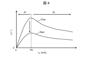
- FIG. 4 is a diagram showing the relationship between the slip speed vs between the wheel 21 and the rail 22 and the tangential force coefficient ⁇ .
- the horizontal axis represents the slip speed vs
- the vertical axis represents the tangential force coefficient ⁇ .
- the tangential force coefficient ⁇ changes depending on the slip speed vs , which is the difference between the wheel circumferential speed and the vehicle body speed. That is, as the slip speed V s increases from 0, the tangential force coefficient ⁇ increases up to the inflection point Ph, but after passing the inflection point Ph, the slip speed V s decreases.
- the wheels 21 and the rails 22 are in a sticky state Jn, but after the inflection point Ph, the wheels 21 and the rails 22 are in an idling state Jk.
- the tangential force coefficient ⁇ is lower than in fine weather, Fine, and slipping and skidding is more likely to occur. It is known that the tangential force coefficient ⁇ changes not only due to rainy weather but also due to oil, fallen leaves, and dust on the rail road surface. It is also known that the tangential force coefficient ⁇ changes when the flange portion of the wheel 21 is pressed against the side surface of the rail 22 in a curved section, etc., and also changes depending on the gradient and vehicle speed. .
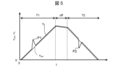
- FIG. 5 is a diagram showing the slipping and sliding of the vehicle 20 during power running and regeneration.
- the horizontal axis represents the time t
- the vertical axis represents the speeds v car and v s of the wheels 21 and the vehicle 20.
- the solid line is the rotational speed of the wheel 21, and the dotted line is the speed of the vehicle 20.
- FIGS. 6(a) to 6(m) are schematic diagrams of operations for suppressing the occurrence of slipping and skidding according to the present embodiment.
- a situation in which the adhesion coefficient decreases in some travel sections while the vehicle 20 is traveling will be described as an example.
- the fact that slipping occurred on the front axis (1st axis) means that the torque of the front axis (1st axis) was greater than the maximum adhesion force in this traveling section, as explained in Figures 3 to 5. means.
- the rear axles (2nd to 4th axles) pass through the same travel section, if they are operated with the same torque as the front axle (1st axle), there is a possibility that the wheels 21 will slip and skid as well. is high.
- the front axis (first axis) in the traveling direction of the vehicle 20 is used as a sensor to detect the condition of the rail road surface, so that it detects the traveling section where the tangential force is reduced and the motor that can output in the traveling section. Detects torque (maximum adhesive force). Then, on the rear axes (2nd to 4th axes) in the traveling direction of the vehicle 20, the torque is controlled to an appropriate magnitude in an appropriate traveling section based on the detection information of the front axis (1st axis).
- the rear axis (2nd to 4th axes) will be able to prevent the occurrence of slipping and achieve maximum adhesion. Can be driven nearby. As a result, the effects of reducing vehicle body vibration and improving acceleration can be obtained.
- the tangential force coefficient ⁇ changes in a complicated manner due to various factors. This includes factors with a long time axis such as seasons and weather, as well as factors with a short time axis that change from moment to moment during driving, such as curves, slopes, rail joints, and lubricators. In particular, it is difficult to respond immediately to the latter factor with a short time axis using a method based on the number of past detections or a method based on prior modeling based on theory or past experimental data, as in the prior art. For these reasons, the inventors considered using the front axis (one axis) to grasp the latest road surface condition.
- FIGS. 6(b) to 6(m) the horizontal axis represents time t.
- the forward axis one axis 211
- the single-axis rotation frequency Rf1 increases at time t1
- the slip-sliding detection determination unit 15 detects that the wheel 21 of the front axis (first shaft 211) is slipping. Detect what has occurred.
- FIG. 2 the slip-sliding detection determination unit 15
- the time t2 for each of the rear axles (2nd to 4th axes 214) to reach the traveling position x1 where the front axle (1st axle 211) has detected idling is calculated as the time t2. , time t3, and time t4.
- the adhesion coefficients Nk1 to Nk4 of the front axis (1st axis 211) and the rear axis (2nd axis 212 to 4th axis 214) change over time. It is thought that the change will occur as shown in the figure.
- the adhesion coefficient Nk1 of the front axis (1st axis 211) decreases, and at times t2, t3, and t4, the adhesion coefficients Nk2 to Nk4 of each rear axis (2nd axis 212 to 4th axis 214) decrease. .
- the torque command calculation unit 11 limits the torque command value ⁇ m * of the front axis (first axis 211), and causes the wheel 21 to readhere to the rail 22. let Then, the torque command calculation unit 11 quickly restores the torque after the readhesion is completed.
- the torque limiter 32 limits the torque command value ⁇ m * based on the history of torque information calculated on the front axis (1st axis 211), so that the torque command value (post-limitation) ⁇ m * Output * . In reality, as shown in FIGS.
- the torque limiting unit 32 sets the torque command value ⁇ m of each rear axis (2nd axis 212 to 4th axis 214) at times t2, t3, and t4. * Limit. Then, the torque limiter 32 outputs torque limit values ⁇ m_2 ** to ⁇ m_4 ** for the 2nd to 4th axes. As a result, it is possible to suppress the wheels 21 from spinning on the rear axles (2nd to 4th axles 212 to 214).
- the rotational frequencies Rf2 to Rf4 of the 2nd to 4th axes do not increase at times t2, t3, and t4, indicating that the wheel 21 does not spin.
- the torque command calculation unit 11 operates on a first axle that is arranged on a first axle (in this case, the front axle (first axle 211)) as an axle connected to the rotating electric machine 4 that generates the driving force that drives the vehicle 20.
- the first driving force for the first axle in this case, the torque command value ⁇ m *
- the limited first driving force corresponds to the limited torque command value ⁇ m * .
- the torque limiting section 32 is arranged on a second axle (in this case, the rear axle (2nd to 4th axle 212)) which is an axle located rearward from the first axle with respect to the traveling direction of the vehicle 20.
- the second wheel in this case, the wheel 21 arranged on the rear axle (2nd axle 212 to 4th axle 214) stick
- the second wheel is applied to the second axle.
- the second driving force after the limitation is the torque command value (after limitation) ⁇ m * . Corresponds to * .
- the point where the first driving force is limited is the location where the first wheel slips or slides.
- the torque command calculation unit 11 limits the first driving force, and the torque limiter 32 prevents the first wheel from spinning or skidding.
- the second driving force is limited at the point where it occurs. This makes it possible to suppress the wheels 21 arranged on the rear axles (2nd to 4th axles 212 to 214) from spinning or sliding.
- the traveling position calculating section 30 calculates the traveling positions of the rear axes (2nd to 4th axes 212 to 214) using the front axis (1st axis 211) as a reference. Then, when the running position of the rear axles (2nd axle 212 to 4th axle 214) reaches a point where the wheels 21 arranged on the front axle (1st axle 211) slip and skid, the torque limiting section 32 Limits the driving force for the axes (2nd axis 212 to 4th axis 214).
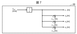
- FIG. 7 is a diagram showing an example of the traveling position calculation section 30.
- the traveling position calculation unit 30 integrates the vehicle speed v car (shown as "1/s" in the figure) and calculates the relative traveling position of the rear axes (2nd to 4th axes) with respect to the front axis (1st axis) x 2 ⁇ Calculate x 4 .
- the vehicle speed information including the vehicle speed v car
- a value received from the upper control device 50 (see FIG. 1) of the control device 2 is used. Therefore, here, the traveling position calculating section 30 calculates the traveling position based on the traveling distance. Further, the running position calculating section 30 can also calculate the running position based on the time taken to reach this position.
- the torque limiter 32 determines the distance between the front axis (1st axis) and the rear axle (2nd to 4th axes) (the distance between the 1st and 2nd axles) to distance x 12 , distance between the 1st and 3rd axes x 13 , distance between the 1st and 4th axes x 14 ), and the speed of the vehicle 20 (vehicle speed v car ). In this case, the location where the first wheel slips or skids can be easily calculated.
- FIG. 8 and 9 are diagrams showing modified examples of the traveling position calculating section 30.
- a traveling position calculating section 30a is illustrated as a modification of the traveling position calculating section 30.
- the traveling position calculation unit 30a corrects the influence of the wheel diameter difference on the circumferential speed v w1 to v w4 of each wheel 21 of the first to fourth axes (shown as "Hs" in the figure), and then integrates the circumferential speed (shown as "Hs" in the figure). 1/s”), and find the relative traveling positions x 2 to x 4 of the rear axes (2nd to 4th axes) with respect to the front axis (1st axis).
- FIG. 8 and 9 are diagrams showing modified examples of the traveling position calculating section 30.
- a traveling position calculating section 30a is illustrated as a modification of the traveling position calculating section 30.
- the traveling position calculation unit 30a corrects the influence of the wheel diameter difference on the circumferential speed v w1 to v
- the circumferential speeds of the wheels 21 on the 1st to 4th axes are shown as 1st axis circumferential speed v W1 , 2nd axis circumferential speed v W2 , 3rd axis circumferential speed v W3 , and 4th axis circumferential speed v W4 , respectively. There is. By correcting the wheel diameter difference, the traveling position can be determined with higher accuracy.
- a traveling position calculating section 30b is illustrated as a modification of the traveling position calculating section 30.
- the running position calculation unit 30b corrects the influence of the wheel diameter difference on the circumferential speed of each wheel 21 of the rear axle (2nd to 4th axle) excluding the front axle (1st axle) that is slipping and sliding (indicated as "Hs" in the figure). ) and then find these minimum values. Then, the minimum value is integrated (shown as "1/s" in the figure) to calculate the relative traveling positions x 2 to x 4 of the rear axes (2nd to 4th axes) with respect to the front axis (1st axis).
- the minimum value is integrated (shown as "1/s" in the figure) to calculate the relative traveling positions x 2 to x 4 of the rear axes (2nd to 4th axes) with respect to the front axis (1st axis).
- the circumferential speeds of the wheels 21 on the 2nd to 4th axes are shown as a 2nd axis circumferential speed v W2 , a 3rd axis circumferential speed v W3 , and a 4th axis circumferential speed v W4, respectively.
- the running position was determined by integrating the vehicle speed v car , but if information corresponding to the running position can be directly received from the upper control device 50 of the control device 2, this information may be used. You can.
- the torque information calculation unit 31 calculates the history of torque information with respect to the traveling position at the time of detection of slipping and skidding on the front axis (one axis).
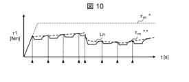
- FIG. 10 is a diagram showing an example of a torque command value held in the torque information calculation section 31.
- the horizontal axis represents time t
- the vertical axis represents torque ⁇ 1 of the front axis (first axis).
- idling occurs when the torque command value exceeds the maximum adhesive force.
- the torque command value (after operation by readhesion control) ⁇ m ** shown by the solid line is limited to the original torque command value (torque command value ⁇ m * ) shown by the upper dotted line.
- the torque command value is set along the adhesion limit line Ln indicated by the lower dotted line, and the torque is narrowed down by re-adhesion control and the torque return operation (returning the torque command to the original torque command value) is performed after the re-adhesion is completed. repeat the action of trying to return).
- the portions indicated by ⁇ are the timing at which the torque command value is held.
- the torque at the time of slipping is held and treated as torque information.
- the adhesion limit line maximum adhesion force
- the magnitude of the torque command value at which slipping occurs also changes accordingly, as shown in the figure.
- the torque command value at the time of slip detection is the maximum adhesion torque for this traveling position.
- the torque information calculation unit 31 generates a history of torque information for the traveling position based on the torque command value at the time of wheel slip detection.
- FIG. 11 is a diagram showing an example of the history of generated torque information.
- the horizontal axis represents the traveling position x
- the vertical axis represents the torque information ⁇ i.
- the white dots indicate locations that are calculated by the torque information calculation section 31 as the history of torque information. That is, this white point indicates the relationship between the traveling position where idling was detected and the torque command value at this traveling position.
- the history of torque information acquired by the method described in FIG. 10 is treated as table data for traveling positions, for example.
- the history of torque information only needs to represent the relationship between the traveling position and the torque information, and may be treated as a function.
- the history of torque information may be referred to as a "torque limit table”.
- the line connecting these white points is defined as the torque limit value.
- FIG. 11 is a diagram showing the torque limit value with respect to the traveling position.
- the torque limiter 32 uses the torque limit table 40 to determine the torque command value for the rear axes (2nd to 4th axes) so that it is equal to or less than the torque limit value.
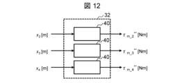
- FIG. 12 is a diagram showing an example of the configuration of the torque limiting section 32. As shown in FIG. The torque limiter 32 limits the torque command value of the rear axes (2nd to 4th axes) to be equal to or less than the torque limit value determined by the torque limit table 40.
- a case is shown in which the torque limiter 32 limits the torque command value ⁇ m * using the torque limit table 40 according to the traveling position.
- the running positions of each rear axle (2nd to 4th axes) are shown as a 2-axis running position x 2 , a 3-axis running position x 3 , and a 4-axis running position x 4 , respectively.
- the torque command value ⁇ m * is a 2-axis torque limit value ⁇ m_2 ** , a 3-axis torque limit value ⁇ m_3 ** , and a 4-axis torque limit value ⁇ for each of the rear axes (2 to 4 axes).
- the torque limiter 32 sets the second driving force (in this case, the torque command value ⁇ m * ) based on the limited first driving force (in this case, the torque command value ⁇ m * after limitation).
- the torque limiter 32 sets the limited second driving force to the torque limit value determined from the history of the limited first driving force (in this case, the limited torque command value ⁇ m * ).
- the torque command value (after limitation) ⁇ m ** ) is determined.
- the second driving force after restriction corresponds to the two-axis torque limit value ⁇ m_2 ** , the three-axis torque limit value ⁇ m_3 ** , and the four-axis torque limit value ⁇ m_4 ** .
- FIG. 13 is a diagram showing a modification of the torque limiting section 32. As shown in FIG. FIG. 13 shows a torque limiting section 32a as a modification of the torque limiting section 32.
- the illustrated torque limiter 32a includes a torque limit value adjuster 33, as compared to the case shown in FIG.
- the torque limit value adjustment section 33 includes a smoothing filter 41 and an adjustment gain 42.
- the smoothing filter 41 smoothes the limited first driving force (in this case, the limited torque command value ⁇ m * ).
- the torque limiter 32a then limits the second driving force. Then, as torque limit values, a 2-axis torque limit value ⁇ m_2 ** , a 3-axis torque limit value ⁇ m_3 ** , and a 4-axis torque limit value ⁇ m_4 ** are determined.
- the smoothing filter 41 uses, for example, a low-pass filter.
- the smoothing filter 41 can suppress vehicle body vibration due to sudden changes in the torque limit value.
- the adjustment gain 42 is used to adjust the front side, such as removing fallen leaves and moisture from the rail 22 when the front axis (1st axis) passes, and the difference in axle load between the front axis (1st axis) and the rear axle (2nd to 4th axis). Correct the difference that may occur between the axis (1st axis) and the rear axis (2nd to 4th axis).
- the adjustment gain 42 can be corrected for each axis using the adjustment gain G having a set value as shown in FIG.
- FIG. 14 shows the value of the adjustment gain G of each rear axis (2nd axis 212 to 4th axis 214) when the front axis (1st axis 211) is 1.0.
- the torque limiter 32 sets a value obtained by multiplying the limit torque by the value of the adjustment gain 42 as a torque command value. In this way, the torque limiter 32a controls the limited first driving force (in this case, the torque command value ⁇ m * after limitation) determined for each rear axis (2nd axis 212 to 4th axis 214). The second driving force is limited after adjusting with the adjustment gain. Then, the torque limiter 32a obtains a two-axis torque limit value ⁇ lim2 , a three-axis torque limit value ⁇ lim3 , and a four-axis torque limit value ⁇ lim4 as the torque limit values. This makes it possible to prevent the rear axes (2 to 4 axes) from idling while each axle can be operated near the maximum adhesion torque.
- the torque limiter 32a controls the limited first driving force (in this case, the torque command value ⁇ m * after limitation) determined for each rear axis (2nd axis 212 to 4th axis
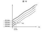
- FIG. 15 and 16 are diagrams showing outlines of operating waveforms when this embodiment is applied.
- FIG. 15 is a diagram showing a torque waveform.
- the horizontal axis represents traveling position x
- the vertical axis represents 1-axis torque ⁇ 1 to 4-axis torque ⁇ 4.
- the torque waveform shown in FIG. 15 it can be seen that for the front axis (first axis), the torque (first axis torque ⁇ 1) fluctuates up and down by repeating idling and readhesion.
- the rear axes (2nd to 4th axes) operate near the maximum adhesion force while suppressing the idling after the travel position X1 where the idling was detected in the front axis (1st axis).
- the torques (2-axis torque ⁇ 2 to 4-axis torque ⁇ 4) change smoothly.
- the torque limit for the rear axles (2nd to 4th axes) is not accurate and errors occur, and as shown for the 2nd and 4th axles in Figure 15, some parts of the rear axle also slip. There are cases where In FIG. 15, this is shown at point K1 and point K2. In this case, slipping is detected using the same means as for the front axis (first axis), and readhesion is performed using readhesion control.
- FIG. 16 is a diagram showing the rotational frequency of the wheel 21.
- the horizontal axis represents time
- the vertical axis represents the rotational frequency of the wheels 21 (1st axis rotational frequency Rf1 to 4th axis rotational frequency Rf4).
- the front axis (one axis) repeats idling and readhesion.
- the rotation frequency of the wheel 21 (uniaxial rotation frequency Rf1) increases or decreases.
- the times t2, t3, and t4 are the times when each rear axle (2 to 4 axes) reaches the point (traveling position X1) where the front axis (1 axis) idles. It can be seen that thereafter, the rotation frequency of the wheels 21 (two-axis rotation frequency Rf2 to four-axis rotation frequency Rf4) increases stably. However, at point K1 and point K2, idling occurs on each of the 2nd and 4th axes.
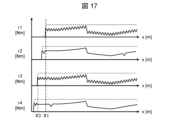
- FIGS. 17 and 18 are diagrams showing outlines of operating waveforms when a modification of the present embodiment is applied.
- FIG. 17 is a diagram showing a torque waveform, similar to FIG. 15.
- FIG. 18 is a diagram showing the rotation frequencies of the wheels 21 (1-axis rotation frequency Rf1 to 4-axis rotation frequency Rf4).
- the horizontal axis represents traveling position x
- the vertical axis represents 1-axis torque ⁇ 1 to 4-axis torque ⁇ 4.
- the sensor axes (front axes) for detecting the road surface condition are one axis and three axes. This can also be said to mean that there is a plurality of first axles (one axle, three axles).
- the torque on the second axis is limited based on the information on the first axis (front axis)
- the torque on the fourth axis (rear axis) is limited based on the information on the third axis (front axis).
- the front axis (1st axis) repeats slipping and re-adhesion, but the rear axis (2nd axis) moves after the traveling position X1 where slipping was detected on the front axis (1st axis). , it can be seen that it operates near the maximum adhesive force while suppressing slippage.
- time t2 is the time when the rear axle (2nd axis) reaches the point (traveling position This is the time when the axes (three axes) reach the idle position (traveling position X3).
- a more accurate torque limit value can be obtained for the rear axes (2 axes, 4 axes).
- FIG. 19 is a diagram showing an example of the case where this embodiment is applied to the organization of vehicles 20.
- M1-1 axis the information on the first axis (M1-1 axis) of the M1 car, which is an M car
- slipping and skidding of the 2nd to 4th axles (M1-2 to 4th axes) of the M1 car is suppressed.
- M2 car which is another M car
- the 2nd to 4th axles (M2-2 to 4th axles) of the M2 car are suppressed from slipping.
- FIG. 20 is a diagram showing a first modification example in which this embodiment is applied to the organization of vehicles 20.
- Figure 20 based on the information on the 1st axle (M1-1 axis) of the M1 car, which is an M car, M2-1 to M2-4 axes) to suppress slipping and sliding. Communication of traveling position and torque information between the control device 2 of the M1 vehicle and the control device 2 of the M2 vehicle is performed, for example, via the host control device 50.
- the idling position and torque information of one axis (M1-1 axis) of the M1 vehicle are transmitted to the host controller 50.
- the host controller 50 transmits the idling position and torque information of the first axis (M1-1 axis) of the M1 vehicle to the 1st to 4th axes (M2-1 to 4th axes) of the M2 vehicle.
- the second axles (M2-1 to M2-4 axes) are the axles of a vehicle different from the vehicle in which the first axle (M1-1 axle) is arranged. In this case, based on the information on the vehicle 20 in front, it is possible to suppress the vehicle 20 in the rear from slipping and sliding.
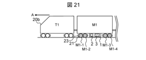
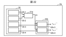
- FIG. 21 is a diagram showing a second modification example in which this embodiment is applied to the organization of vehicles 20.
- the sensor axes (front axes) for detecting the road surface condition are the 1st and 2nd axes of the M1 vehicle. Then, based on the information on the 1st and 2nd axles (M1-1, 2nd axle) of the M1 car, slipping and skidding of the 3rd and 4th axles (M1-3, 4th axis) of the M1 car is suppressed.
- FIG. 22 is a diagram showing the configuration of a control device 2a as a modification of the control device 2 to which the configuration of FIG. 21 is applied.
- the control device 2 a includes a travel position calculation section 30 , a torque information calculation section 31 a that is a modification of the torque information calculation section 31 , and a torque restriction section 32 b that is a modification of the torque restriction section 32 .
- the traveling position calculating section 30 is provided for each of the 1st to 4th axes.
- the torque information calculation unit 31a outputs a history R1 of torque information when the vehicle 20 is idling and sliding on one and two axles located on the front side in the traveling direction A. That is, the first and second axes are taken as sensor axes.
- the torque limiting section 32b inputs the history of torque information of the 1st and 2nd axes and the running position calculation results of the 3rd and 4th axes calculated by the running position calculating section 30, and controls the rear side of the vehicle 20 in the traveling direction A. Outputs the torque limit value ⁇ m_3 ** ⁇ ⁇ m_4 ** of the 3rd to 4th axes located.
- the torque limiter 32b is provided for each of three to four axes. In FIG. 22, the torque limiters are shown as a torque limiter (three axes) 32b-3 and a torque limiter (four axes) 32b-4, respectively.
- FIG. 23 is a diagram showing an example of the history of torque information ⁇ i when the configuration of FIG. 21 is applied.
- the torque limit value for the 1st axis is the torque limit value (1st axis) ⁇ m_1 **
- the torque limit for the 2nd axis is the torque limit value (1st axis) ⁇ m_1 **
- the torque limit value (two axes) ⁇ m_2 ** is calculated as the value. Then, for example, these minimum values and these average values are set as the history of torque information ⁇ i.
- FIG. 24 is a diagram showing an example of a case where this embodiment is applied to a plurality of train sets traveling on a railway.
- idle information (history of running position and torque information) is transmitted and received between formation N+1, formation N, and formation N-1, which are located in the front and rear of the vehicle 20 in the traveling direction A, via the communication server 51.
- the figure shows the case where In this case, idle information I N+1 of formation N+1 is sent to formation N via the communication server 51. Further, the idle information I N of formation N is sent to formation N-1 via the communication server 51. Furthermore, the idle information I N- 1 of formation N-1 is further sent to subsequent formations via the communication server 51. Any method may be used to send and receive the idle information as long as the idle information can be exchanged between the formations, but for example, it may be a method in which the upper control device 50 communicates data with the communication server 51 using Wi-Fi. I can do it.
- Formation N receives idling information I N+1 of formation N+1 (not shown) running ahead. By manipulating the torque at the same traveling position using the received slip information I N+1 , it is possible to prevent slip even on the leading axle of M cars of formation N.
- the idling information I N history of running position and torque information obtained from formation N is then transmitted to the subsequent formation (formation N-1), and is sent to the leading axle of the M car of the subsequent formation (formation N-1). Similarly, the effect of preventing idling can be obtained.
- the torque limiter 32 of the formation N controls the wheels 21 of the vehicles 20 of another formation (for example, formation N+1) running in front of the formation (for example, formation N) in which the own device is provided.
- the first driving force in this case , it can also be said that the torque command value ⁇ m * ) before limitation is limited.
- the torque command value ⁇ m * before limitation is limited.
- the amount of torque operation is changed based on the difference in the occupancy rate (axle load) of the car between the front and rear formations using the configurations shown in FIGS. 13 and 14. It may also be a configuration. Note that since it is necessary to define the traveling position across the formations, a configuration may be adopted in which position information (in kilometers) etc. held by the higher-level control device 50 is used.
- FIG. 25 and 26 are diagrams showing outlines of operating waveforms when this embodiment is applied.
- FIG. 25 is a diagram showing the torque waveform of M cars of formation N.
- the horizontal axis represents traveling position x
- the vertical axis represents 1-axis torque ⁇ 1 to 4-axis torque ⁇ 4.
- the front axis (first axis) operates near the maximum adhesion force while suppressing the slip based on the slip information of formation N+1 traveling ahead.
- the rear axes (2nd to 4th axes) operate near the maximum adhesion force while similarly suppressing slippage.
- FIG. 25 as compared to the case of FIG. 15, it is possible to suppress not only the rear shaft (2 to 4 shafts) but also the front shaft (1 shaft) from idling.
- FIG. 26 is a diagram showing the rotation frequency of the wheel 21.
- the horizontal axis represents time t
- the vertical axis represents the rotational frequency of the wheels 21 (1st axis rotational frequency Rf1 to 4th axis rotational frequency Rf4).
- the rotation frequency of the wheels 21 increases stably on both the front axis (1st axis) and the rear axis (2nd to 4th axis).
- FIG. 26 compared to the case of FIG. 16, not only the rotational frequency of the wheels 21 of the rear axis (2nd to 4th axis) but also of the front axis (1st axis) can be stabilized.
- FIG. 27 is a diagram showing an example of a case where a synchronous machine 4a is used as the rotating electric machine 4.
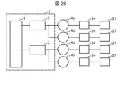
- FIG. 28 is a diagram showing an example of a case where an induction machine 4b is used as the rotating electrical machine 4.
- each shaft of the wheel 21 is shown to be connected to the synchronous machine 4a and the induction machine 4b via the gear 24, respectively.
- a 1C1M configuration can be used. That is, as shown in FIG. 27, one voltage output device 3 is arranged for each synchronous machine 4a.
- each axis can be controlled individually, any of the configurations shown in FIGS. 19 to 21 can be supported.
- the configuration is 1C2M. That is, as shown in FIG. 28, one voltage output device 3 is arranged for two induction machines 4b. Therefore, in this case, the configuration in which the two induction machines 4b are driven in parallel is suitable, for example, as shown in FIG. 21.
- the front shaft is used as a so-called sensor shaft for detecting the road surface condition, and the wheels 21 of the rear shaft are prevented from slipping and sliding.
- this is applied to the formation traveling ahead and also to the subsequent formation. In this case, it is possible to suppress the wheels 21 from slipping and sliding in response to various road surface conditions.
- the rotating electric machine 4 can be operated near the maximum adhesive force without steep torque operation, and it is possible to reduce vehicle body vibration and improve acceleration at the same time.
- the traveling position calculation unit 30 is merely an example, and it is sufficient to define the relative positional relationship of the rear axes (2 to 4 axes) to the front axis (1 axis), and it is sufficient to define not only the traveling position but also the time corresponding to it. etc. may also be used.
- the front axis with respect to the traveling direction is one axis
- the forward side with respect to the traveling direction The side axes are 4 axes, and the system is operated in a configuration that limits the torque of the rear axes (1 to 3 axes) based on the information of the front axes (4 axes).
- the second embodiment differs from the first embodiment in that an estimated value of the tangential force calculated by an observer is used as the history of torque information calculated by the torque information calculation unit 31, and other aspects are the same. It is.
- ⁇ m * is the torque command value
- J W * is the rotor inertia of the driving wheel shaft
- ⁇ m ⁇ is the estimated value of the rotor angular frequency
- T LPF is the first-order low-pass filter time constant
- s is the Laplace operator. do.
- FIGS. 29(a) and 29(b) are diagrams comparing the history of torque information generated in the first embodiment and the history of torque information generated in the second embodiment.
- FIG. 29(a) is the history of torque information generated in the first embodiment
- FIG. 29(b) is the history of torque information generated in the second embodiment.
- the torque information calculation unit 31 creates a history of torque information using the torque command value. That is, the torque command value (after operation by readhesion control) ⁇ m ** shown by the solid line is limited with respect to the original torque command value (torque command value ⁇ m * ) shown by the upper dotted line.
- the torque command value is set along the adhesion limit line Ln indicated by the lower dotted line, and the torque is narrowed down by re-adhesion control and the torque return operation (returning the torque command to the original torque command value) is performed after the re-adhesion is completed. repeat the action of trying to return).
- the portions indicated by ⁇ are the holding timings of the torque command value. Then, the torque at the time of slipping is held and treated as torque information. In this case, the limit line of adhesion can only be grasped when slipping and skidding is detected.
- the torque information calculation unit 31 uses an observer that estimates the tangential force as shown in Equation 1 above. As a result, the maximum adhesion torque can be estimated not only when slipping and sliding is detected, but also in the process of transitioning from the slipping and sliding state to the adhesion state. As a result, the torque information calculation unit 31 can increase the number of times of sampling for determining the adhesion limit line. Then, the torque limiting unit 32 uses the tangential force on the wheel 21, which is estimated in the process of transitioning to the sticky state after the wheel 21 disposed on the front axle has spun or skid, to control the rear axle. Outputs torque limit value. This makes it possible to estimate the maximum adhesive force more accurately. In FIG.
- the portions indicated by ⁇ are the holding timings of the torque command value. Further, the portion indicated by ⁇ is the recording timing at the time of transition from the idling state to the sticky state. Then, the torque command value or tangential force estimated value at the time of occurrence of slipping and the tangential force estimated value at the time of transition from the slipping state to the sticky state are held and treated as torque information.
- FIG. 29(b) describes the case where only the observer for estimating the tangential force is used, a method may also be used in which the torque command value is used in combination.
- the drive device 1 for the rotating electric machine 4 uses the estimated value of the tangential force (tangential force torque estimated value ⁇ L ⁇ ) is used. This makes it possible to more accurately grasp the maximum adhesion force relative to the traveling position. Furthermore, it is possible to further reduce vehicle body vibration and improve acceleration.
- the repetition period of readhesion control (the frequency of repetition of tightening and raising torque) for the front axis (1st axis) is different from that of the rear axis (2nd to 4th axes). The difference is that it is faster than , but the other things are the same.
- FIGS. 30A and 30B are diagrams comparing the history of torque information generated in the first embodiment and the history of torque information generated in the third embodiment.
- FIG. 30(a) is a history of torque information generated in the first embodiment, and corresponds to a case where the frequency of readhesion control is low. In this case, the sampling interval of the torque information is time T3, and the sampling of the torque information is coarse.
- this is the history of torque information generated in the third embodiment, and corresponds to a case where readhesion control is performed frequently. In this case, the sampling interval of the torque information is time T4, and the sampling of the torque information is fine. In other words, T3>T4.
- FIG. 30(b) compared to the case of FIG.
- the torque operation for readhesion control in the torque command calculation unit 11 of the front axis (1st axis) is The repetition period of the readhesion control is made faster than the previous one.
- the torque command calculation unit 11 limits the frequency of limiting the first driving force (in this case, torque command value ⁇ m * before limitation), and the torque limiting unit 32 controls the frequency of limiting the second driving force (in this case, the limit It can also be said that the previous torque command value ⁇ m * ) is limited more frequently than the previous torque command value ⁇ m *).
- the drive device 1 for the rotating electric machine 4 makes the repetition cycle of the readhesion control of the front shaft (1st shaft) faster than that of the rear shafts (2nd to 4th shafts).
- the maximum adhesion force relative to the traveling position can be more accurately grasped. This makes it possible to further reduce vehicle body vibration and improve acceleration.
- the process performed by the control device 2 is to attach the wheels 21 arranged on the first axle as an axle connected to the rotating electrical machine 4 that generates the driving force for driving the vehicle 20 to the first axle.
- the first driving force to the first axle and to make the wheels 21 attached to the second axle, which is the axle located rearward from the first axle with respect to the traveling direction of the vehicle 20, stick.
- This can be considered as a vehicle control method that limits the second driving force to the second axle at the point where the second driving force is limited.
Landscapes
- Engineering & Computer Science (AREA)
- Power Engineering (AREA)
- Transportation (AREA)
- Mechanical Engineering (AREA)
- Life Sciences & Earth Sciences (AREA)
- Sustainable Development (AREA)
- Sustainable Energy (AREA)
- Electric Propulsion And Braking For Vehicles (AREA)
Priority Applications (2)
| Application Number | Priority Date | Filing Date | Title |
|---|---|---|---|
| EP23849869.5A EP4566865A1 (en) | 2022-08-05 | 2023-07-13 | Vehicle control device, vehicle control method, and vehicle control system |
| JP2024538900A JP7836401B2 (ja) | 2022-08-05 | 2023-07-13 | 車両制御装置、車両制御方法および車両制御システム |
Applications Claiming Priority (2)
| Application Number | Priority Date | Filing Date | Title |
|---|---|---|---|
| JP2022125331 | 2022-08-05 | ||
| JP2022-125331 | 2022-08-05 |
Publications (1)
| Publication Number | Publication Date |
|---|---|
| WO2024029310A1 true WO2024029310A1 (ja) | 2024-02-08 |
Family
ID=89849269
Family Applications (1)
| Application Number | Title | Priority Date | Filing Date |
|---|---|---|---|
| PCT/JP2023/025921 Ceased WO2024029310A1 (ja) | 2022-08-05 | 2023-07-13 | 車両制御装置、車両制御方法および車両制御システム |
Country Status (3)
| Country | Link |
|---|---|
| EP (1) | EP4566865A1 (https=) |
| JP (1) | JP7836401B2 (https=) |
| WO (1) | WO2024029310A1 (https=) |
Citations (3)
| Publication number | Priority date | Publication date | Assignee | Title |
|---|---|---|---|---|
| JP2003348706A (ja) * | 1996-09-25 | 2003-12-05 | Hitachi Ltd | 車両用電力変換器の制御装置 |
| JP2010028982A (ja) * | 2008-07-22 | 2010-02-04 | Railway Technical Res Inst | 電気車制御方法及び電気車制御装置 |
| JP2011004549A (ja) * | 2009-06-19 | 2011-01-06 | Hitachi Ltd | 列車制御システム |
-
2023
- 2023-07-13 JP JP2024538900A patent/JP7836401B2/ja active Active
- 2023-07-13 EP EP23849869.5A patent/EP4566865A1/en active Pending
- 2023-07-13 WO PCT/JP2023/025921 patent/WO2024029310A1/ja not_active Ceased
Patent Citations (3)
| Publication number | Priority date | Publication date | Assignee | Title |
|---|---|---|---|---|
| JP2003348706A (ja) * | 1996-09-25 | 2003-12-05 | Hitachi Ltd | 車両用電力変換器の制御装置 |
| JP2010028982A (ja) * | 2008-07-22 | 2010-02-04 | Railway Technical Res Inst | 電気車制御方法及び電気車制御装置 |
| JP2011004549A (ja) * | 2009-06-19 | 2011-01-06 | Hitachi Ltd | 列車制御システム |
Also Published As
| Publication number | Publication date |
|---|---|
| JPWO2024029310A1 (https=) | 2024-02-08 |
| EP4566865A1 (en) | 2025-06-11 |
| JP7836401B2 (ja) | 2026-03-26 |
Similar Documents
| Publication | Publication Date | Title |
|---|---|---|
| JP6540716B2 (ja) | 車両の制御装置および車両の制御方法 | |
| CN101678773A (zh) | 电车的控制装置 | |
| JP7755691B2 (ja) | 回転電機の駆動装置、駆動方法および鉄道車両 | |
| JP4850870B2 (ja) | 電気車制御方法及び電気車制御装置 | |
| CN1842432B (zh) | 电车控制装置 | |
| JP5643271B2 (ja) | 空転滑走発生検出方法及び電動機制御装置 | |
| WO2024029310A1 (ja) | 車両制御装置、車両制御方法および車両制御システム | |
| JPH06217410A (ja) | 誘導電動機式電気車の制御装置 | |
| JPWO2022118822A5 (https=) | ||
| JP4818244B2 (ja) | 電動機制御装置及び再粘着制御方法 | |
| JP2020174531A (ja) | 電動機制御方法および制御装置 | |
| JP6017842B2 (ja) | 再粘着制御方法及び電動機制御装置 | |
| JP2009077572A (ja) | 電気車制御装置 | |
| JP2019201459A (ja) | 電動機制御方法及び電動機制御装置 | |
| JPH11103507A (ja) | 車両速度制御装置 | |
| WO2025069932A1 (ja) | 鉄道車両用駆動装置とその制御方法 | |
| JP4342878B2 (ja) | 電気車制御装置 | |
| JP2000125406A (ja) | 電気車制御装置 | |
| JP2009240123A (ja) | 電動機制御方法及び電動機制御装置 | |
| JP6166211B2 (ja) | 復帰制御方法、電動機制御装置及び機械ブレーキ制御装置 | |
| JP7449205B2 (ja) | 電気車の再粘着制御装置 | |
| JP6990112B2 (ja) | 再粘着制御方法および電動機制御装置 | |
| JPH0576243B2 (https=) | ||
| JPH03256504A (ja) | インバータ電気車の制御装置 | |
| JPH06276606A (ja) | 電気車制御装置 |
Legal Events
| Date | Code | Title | Description |
|---|---|---|---|
| 121 | Ep: the epo has been informed by wipo that ep was designated in this application |
Ref document number: 23849869 Country of ref document: EP Kind code of ref document: A1 |
|
| DPE2 | Request for preliminary examination filed before expiration of 19th month from priority date (pct application filed from 20040101) | ||
| WWE | Wipo information: entry into national phase |
Ref document number: 2024538900 Country of ref document: JP |
|
| WWE | Wipo information: entry into national phase |
Ref document number: 2023849869 Country of ref document: EP |
|
| NENP | Non-entry into the national phase |
Ref country code: DE |
|
| ENP | Entry into the national phase |
Ref document number: 2023849869 Country of ref document: EP Effective date: 20250305 |
|
| WWP | Wipo information: published in national office |
Ref document number: 2023849869 Country of ref document: EP |