WO2024028987A1 - 条件提示装置、およびコンピュータ読み取り可能な記憶媒体 - Google Patents
条件提示装置、およびコンピュータ読み取り可能な記憶媒体 Download PDFInfo
- Publication number
- WO2024028987A1 WO2024028987A1 PCT/JP2022/029694 JP2022029694W WO2024028987A1 WO 2024028987 A1 WO2024028987 A1 WO 2024028987A1 JP 2022029694 W JP2022029694 W JP 2022029694W WO 2024028987 A1 WO2024028987 A1 WO 2024028987A1
- Authority
- WO
- WIPO (PCT)
- Prior art keywords
- molding
- molding conditions
- changing
- pressure
- setting
- Prior art date
- Legal status (The legal status is an assumption and is not a legal conclusion. Google has not performed a legal analysis and makes no representation as to the accuracy of the status listed.)
- Ceased
Links
Images




Classifications
-
- B—PERFORMING OPERATIONS; TRANSPORTING
- B29—WORKING OF PLASTICS; WORKING OF SUBSTANCES IN A PLASTIC STATE IN GENERAL
- B29C—SHAPING OR JOINING OF PLASTICS; SHAPING OF MATERIAL IN A PLASTIC STATE, NOT OTHERWISE PROVIDED FOR; AFTER-TREATMENT OF THE SHAPED PRODUCTS, e.g. REPAIRING
- B29C45/00—Injection moulding, i.e. forcing the required volume of moulding material through a nozzle into a closed mould; Apparatus therefor
- B29C45/17—Component parts, details or accessories; Auxiliary operations
- B29C45/76—Measuring, controlling or regulating
Definitions
- the present disclosure relates to a condition presentation device and a computer-readable storage medium.
- condition presentation device that uses an expert system to calculate and present optimal molding conditions for an injection molding machine (for example, Patent Document 1).
- the condition presentation device changes the display mode of a display related to molding conditions based on an acquisition unit that acquires molding conditions for injection molding in an injection molding machine, and the molding conditions and molding condition setting criteria acquired by the acquisition unit. and a recommendation section that recommends changes to molding conditions.
- a computer-readable storage medium acquires molding conditions for injection molding in an injection molding machine, and changes the display mode of a display related to molding conditions based on the acquired molding conditions and molding condition setting standards. , recommending a change in molding conditions, and storing instructions for causing a computer to execute the following.
- condition presentation device that has a simple configuration and is easy to operate for an operator.
- FIG. 2 is a block diagram showing an example of a hardware configuration of a condition presentation device. It is a block diagram showing an example of the function of a condition presentation device.
- FIG. 3 is a diagram showing an example of a display screen that displays molding conditions. It is a figure showing an example of molding data.
- FIG. 3 is a diagram showing an example of a display screen that recommends changing molding conditions.
- FIG. 6 is a diagram illustrating an example of a display mode of setting items that are recommended to be changed. It is a flow chart which shows an example of the flow of processing performed by a condition presentation device.
- FIG. 3 is a diagram showing an example of a display screen that presents recommended values and recommended ranges.
- FIG. 3 is a diagram illustrating an example of a display mode of information indicating a reason for recommending a change in molding conditions.
- FIG. 2 is a block diagram illustrating an example of a function of a condition presentation device including an input reception unit.
- FIG. 6 is a diagram for explaining an example in which a plurality of criteria are set for one setting item.
- FIG. 2 is a block diagram illustrating an example of a function of a condition presentation device including a selection reception unit.
- FIG. 6 is a diagram for explaining an example of recommending a change in molding conditions in different display modes for each setting standard.
- the condition presentation device is a device for presenting the molding conditions of the injection molding machine. Molding conditions are operating conditions when an injection molding machine molds a molded product. The operating conditions include, for example, maximum injection pressure, injection speed, etc. Specific molding conditions will be explained in detail later.
- the condition presentation device is implemented in, for example, a PC (Personal Computer) or a server.
- the condition presentation device may be implemented in a numerical control device that controls the injection molding machine.
- An example in which the condition presentation device is implemented in a PC will be described below.
- FIG. 1 is a block diagram showing an example of the hardware configuration of the condition presentation device.
- the condition presenting device 1 includes a hardware processor 11, a bus 12, a ROM (Read Only Memory) 13, a RAM (Random Access Memory) 14, a nonvolatile memory 15, a first interface 16, and a second and an interface 17.
- the hardware processor 11 is a processor that controls the entire condition presentation device 1 according to a system program.
- the hardware processor 11 reads out a system program stored in the ROM 13 via the bus 12, and performs various processes based on the system program.
- the hardware processor 11 is, for example, a CPU (Central Processing Unit) or an electronic circuit.
- the bus 12 is a communication path that connects each piece of hardware within the condition presentation device 1 to each other. Each piece of hardware within the condition presentation device 1 exchanges data via a bus 12.
- the ROM 13 is a storage device that stores system programs and the like for controlling the entire condition presentation device 1.
- ROM 13 is a computer-readable storage medium.
- the RAM 14 is a storage device that temporarily stores various data.
- the RAM 14 functions as a work area for the hardware processor 11 to process various data.
- the nonvolatile memory 15 is a storage device that retains data even when the condition presentation device 1 is powered off and power is not supplied to the condition presentation device 1.
- the nonvolatile memory 15 stores, for example, molding conditions.
- Non-volatile memory 15 is a computer readable storage medium.
- the nonvolatile memory 15 includes, for example, battery-backed memory or an SSD (Solid State Drive).
- the first interface 16 is a communication path that connects the bus 12 and the numerical control device 2.
- the hardware processor 11 sends various data to the numerical control device 2 via the first interface 16.
- the numerical control device 2 sends various data to the condition presentation device 1 via the first interface 16.
- the second interface 17 is a communication path that connects the bus 12 and the sensor 3.
- the sensor 3 is, for example, a sensor 3 that detects pressure inside a mold of an injection molding machine.
- the nonvolatile memory 15 receives data sent from the sensor 3 via the second interface 17 and stores it.
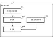
- FIG. 2 is a block diagram showing an example of the functions of the condition presentation device 1.
- the condition presentation device 1 includes, for example, a molding condition storage section 101, an acquisition section 102, a setting criteria storage section 103, and a recommendation section 104.
- the acquisition unit 102 and the recommendation unit 104 are realized, for example, by the hardware processor 11 performing arithmetic processing using a system program stored in the ROM 13 and various data stored in the nonvolatile memory 15.
- the molding condition storage unit 101 and the setting standard storage unit 103 are realized, for example, by storing molding conditions and setting standards input from an external device in the nonvolatile memory 15.
- the molding condition storage unit 101 stores molding conditions. Molding conditions are conditions when injection molding is performed in an injection molding machine.
- the molding conditions include, for example, conditions related to injection, conditions related to holding pressure, and conditions related to metering. Further, the conditions related to injection, the conditions related to holding pressure, and the conditions related to metering each include a plurality of setting items.
- Setting items for conditions related to injection include the number of injection operation stages, maximum injection pressure, injection speed at each stage, and switching position.
- the number of stages of injection operation is an item that defines how many stages injection molding is divided into.
- the switching position is an item that defines the position of the screw when switching each stage of injection molding.
- Setting items for conditions related to pressure holding include the number of stages of pressure holding operation, the pressure and time at each stage.
- the number of stages of pressure holding operation is an item that defines how many stages the pressure holding operation is divided into.
- Setting items for conditions related to metering include the number of stages of metering operation, back pressure at each stage, rotational speed and switching position, cooling time, and depressurization setting.
- the number of steps of the weighing operation is an item that defines how many steps the weighing operation is divided into.
- the rotational speed and switching position are the rotational speed and position of the screw, respectively.
- the condition presentation device 1 may, for example, acquire molding conditions from a mold file stored in association with the type of mold attached to an injection molding machine, and store the molding conditions in the molding condition storage unit 101.
- the condition presentation device 1 may, for example, accept input of molding conditions from an operator and store the input in the molding condition storage unit 101.
- the acquisition unit 102 acquires molding conditions for injection molding in an injection molding machine.
- the acquisition unit 102 acquires the molding conditions stored in the molding condition storage unit 101. If the condition presentation device 1 does not include the molding condition storage unit 101, the acquisition unit 102 may directly acquire the molding conditions input by the operator, for example.
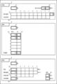
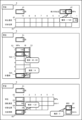
- FIG. 3 is a diagram showing an example of a display screen that displays the molding conditions acquired by the acquisition unit 102.
- the display screen includes a display area 4 showing conditions related to injection, a display area 5 showing conditions related to holding pressure, and a display area 6 showing conditions related to metering.
- the display area 4 showing conditions related to injection includes an area 41 showing the number of injection operation stages, an area 42 showing the maximum injection pressure, an area 43 showing the injection speed at each stage, and an area 44 showing the switching position at each stage.
- the number of stages of the injection operation is set to "1”
- the maximum injection pressure is set to "120" [MPa]
- the injection speed in the first stage is set to "50" [mm/s].
- the display area 5 showing the conditions regarding pressure holding includes an area 51 showing the number of stages of the pressure holding operation, an area 52 showing the pressure at each stage, and an area 53 showing the time of each stage.
- the number of stages of pressure holding operation is "2”
- the pressure of the first stage of holding pressure is "100" [MPa] and "3" [seconds]
- the pressure of the second stage of holding pressure is "3" [seconds].
- the pressure is set to "20" [MPa] and "3" [seconds]
- the holding pressure before measurement is set to "20" [MPa] and "0.2" [seconds].
- the area 6 indicating the conditions related to metering includes an area 61 indicating the number of stages of the metering operation, an area 62 indicating the back pressure at each stage, an area 63 indicating the rotation speed at each stage, and an area 64 indicating the switching position between each stage. It includes an area 65 indicating the cooling time at the time of measurement, and an area 66 indicating the depressurization setting.
- the number of steps in the weighing operation is "1”
- the back pressure during weighing is "4" [MPa]
- the rotation speed is "80" [min -1 ]
- the cooling time is "20" [seconds].
- the decompression setting is set to "20" [mm] and "2" [mm/s].
- the setting standard storage unit 103 stores setting standards for molding conditions.
- the setting standard is an appropriate numerical value or an appropriate numerical range for the molding conditions, and is a standard when setting the molding conditions.
- the setting standards are determined based on the wisdom, experience, know-how, etc. of skilled workers. Further, setting standards are provided for each setting item of molding conditions.
- the setting standard may be at least one of a recommended value of molding conditions and a recommended range of molding conditions.
- the setting criteria may be at least one of a predetermined calculation formula and a predetermined conditional formula.
- the predetermined conditional expression is, for example, a conditional expression using molding data acquired when injection molding is executed.
- the molding data is, for example, waveform data, process data, and external sensor data.
- the waveform data is time series data obtained from the sensor 3 of the injection molding machine.
- the waveform data is, for example, time series data indicating the nozzle pressure of the injection molding machine, or time series data indicating the injection speed.
- the process data is data indicating representative numerical values of waveform data or numerical data obtained through one molding cycle.
- the typical numerical value may be, for example, an average value, an integrated value, a maximum value, or a minimum value of time series data indicated by the waveform data.
- Process data is, for example, nozzle maximum peak pressure, cycle time, metering time.
- the external sensor data is data acquired from a sensor 3 installed outside the injection molding machine.
- the external sensor data is, for example, data acquired by a sensor 3 built into the mold.
- the setting criteria may be determined using machine learning.
- the setting standard can be calculated using MLP (Multilayer perceptron) and multiple regression analysis.
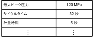
- FIG. 4 is a diagram showing an example of molding data. Molding data includes maximum peak pressure, cycle time, and metering time.
- the setting standard storage unit 103 stores, for example, "0.4x ⁇ y ⁇ 0.6x" as the setting standard for the second-stage holding pressure.
- "y” is the pressure of the second stage of holding pressure
- "x” is the pressure of the first stage of holding pressure.
- the maximum injection pressure needs to be equal to or higher than the maximum peak pressure acquired by the sensor 3. This is because, if the maximum injection pressure is the same as the maximum peak pressure, the pressure during injection molding is considered to be limited by the maximum injection pressure. Therefore, the setting standard storage unit 103 stores the conditional expression "maximum injection pressure>maximum peak pressure" as a setting standard for the maximum injection pressure.
- the setting standard storage unit 103 stores the numerical value 3 [mm] as the setting standard regarding the distance of the decompression setting.
- the value of the pressure before measurement is the pressure change between the pressure at the final stage of holding pressure (in the example shown in Fig. 3, the second stage pressure) and the back pressure at the time of measurement. It needs to be set to a value that makes it smooth. Therefore, in the example shown in FIG. 3, the setting standard storage unit 103 stores, for example, the numerical value "14" [MPa] as the setting standard regarding the pre-measurement pressure. Note that, as a setting standard regarding the pressure before measurement, the setting standard storage unit 103 may store a predetermined conditional expression that takes into consideration the pressure at the final stage of pressure holding and the back pressure during measurement.
- the cooling time is usually set to be sufficiently longer than the measurement time (see FIG. 4). In this case, shortening the cooling time may shorten the cycle time. That is, the cooling time for cooling the already molded product and the measurement of the material for the new molded product are started at the same time, and when both are completed, the next process is started.
- the setting standard storage unit 103 stores the conditional expression “cooling time ⁇ metering time+ ⁇ ” (where ⁇ [seconds] is a predetermined time). In other words, the cooling time can be shortened so as to satisfy this conditional expression.
- the recommendation unit 104 recommends changing the molding conditions by changing the display mode of the display related to the molding conditions based on the molding conditions and molding condition setting criteria acquired by the acquisition unit 102.
- the recommendation unit 104 may recommend changing the molding conditions based on a conditional expression that uses as a variable another molding condition different from the molding condition for which change is recommended.
- the pressure for the first stage holding pressure is set to "100" [MPa]
- the pressure for the second stage holding pressure is set to "20" [MPa].
- ” is set to [MPa].
- the setting standard storage unit 103 stores "0.4x ⁇ y ⁇ 0.6x" as a setting standard for the second-stage holding pressure.
- "y" is the second-stage holding pressure
- "x" is the first-stage holding pressure.
- the second-stage holding pressure is a molding condition that is recommended to be changed, and the first-stage holding pressure and other molding conditions are the same.
- the recommendation unit 104 recommends changing the pressure of the second stage of holding pressure among the conditions related to holding pressure.
- FIG. 5 is a diagram showing an example of a display screen on which the recommendation unit 104 recommends changing the molding conditions.
- the recommendation unit 104 recommends changing the pressure of the second stage of holding pressure, for example, by changing the area 522 indicating the pressure of the second stage of holding pressure from white to red.
- the recommendation unit 104 may recommend changing the molding conditions based on the molding conditions, setting standards, and a conditional expression whose variables are molding data acquired when injection molding is executed. For example, in the example shown in FIG. 3, among the conditions related to injection, the maximum injection pressure is set to "120" [MPa]. Furthermore, the maximum peak pressure obtained was also 120 [MPa] (see FIG. 4). On the other hand, the setting standard storage unit 103 stores the conditional expression "maximum injection pressure>maximum peak pressure" as a setting standard for the maximum injection pressure. In other words, the maximum injection pressure does not meet the set criteria.
- the recommendation unit 104 recommends changing the maximum injection pressure.
- the recommendation unit 104 recommends the operator to change the maximum injection pressure by changing the color of the area 42 indicating the maximum injection pressure from white to red (see FIG. 5).
- the pressure reduction setting is set to "20" [mm].
- the setting standard storage unit 103 stores a numerical value of 3 [mm] as a setting standard for the decompression setting.
- the recommendation unit 104 recommends changing the pressure reduction setting.
- the recommendation unit 104 recommends that the operator change the reduced pressure setting by changing the color of the area 66 indicating the reduced pressure setting from white to red (see FIG. 5).
- the pressure before measurement is set to 20 [MPa].
- the setting standard storage unit 103 stores 14 [MPa] as a setting standard for the pressure before measurement.
- the recommendation unit 104 recommends changing the pressure before measurement.
- the recommendation unit 104 recommends the operator to change the pre-measurement pressure by changing the color of the area 520 indicating the pre-measurement pressure from white to red (see FIG. 5).
- the cooling time is set to 20 [seconds]. Moreover, the acquired measurement time is 5 [seconds].
- the setting standard storage unit 103 stores the conditional expression "cooling time ⁇ metering time + ⁇ " as a setting standard for the cooling time. For example, when ⁇ is 12 seconds, the cooling time does not satisfy this conditional expression.
- the recommendation unit 104 recommends changing the cooling time.
- the recommendation unit 104 recommends that the operator change the cooling time by changing the color of the area 65 indicating the cooling time from white to red (see FIG. 5).
- the display mode of molding conditions can be changed by changing the color of the text indicating the molding conditions, changing the text style, changing the color of the text display area, changing the display of the molding condition icon, and changing the text and display area. It may be a change in the brightness of at least one of them. Changes in character style include, for example, changing the font, changing from solid to italic, and changing from thin to bold.
- Changing the icon display includes, for example, displaying an icon representing a recommendation for change near a display regarding a change in molding conditions.
- the recommendation unit 104 may recommend changing the molding conditions by collectively displaying setting items that are recommended to be changed.
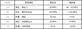
- FIG. 6 is a diagram illustrating an example of a display mode in which setting items recommended to be changed are aggregated and displayed.
- the recommendation unit 104 causes the display screen to display, for example, an image including a link, a setting item whose change is recommended, a current value of the molding condition set in the setting item, and a recommended value.
- a link is a link to a display area where each setting item is displayed. That is, by performing an operation on a right-pointing arrow, it is possible to move to the display area of the setting item associated with the arrow. For example, by performing an operation on the link "holding pressure-holding pressure 2", it is possible to move to the area 522 indicating the pressure of the second stage of holding pressure.
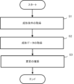
- FIG. 7 is a flowchart showing an example of the flow of processing executed by the condition presentation device 1.
- the acquisition unit 102 acquires molding conditions (step S1).
- the acquisition unit 102 acquires molding data (step S2). That is, the injection molding machine performs injection molding based on the set molding conditions, and the condition presentation device 1 acquires molding data.
- the recommendation unit 104 recommends changes to the molding conditions based on the molding conditions and molding condition setting standards acquired by the acquisition unit 102, or based on the molding conditions, setting standards, and molding data. Step S3), the process ends.
- the condition presentation device 1 uses the acquisition unit 102 that acquires the molding conditions of injection molding in the injection molding machine, and the molding conditions based on the molding conditions and molding condition setting criteria acquired by the acquisition unit 102.
- a recommendation section 104 that recommends changing the molding conditions by changing the display mode of the display is provided.
- the recommendation unit 104 also performs molding based on a conditional expression that has as a variable at least one of molding conditions different from the molding conditions for which change is recommended and molding data acquired when injection molding is executed. Recommend changing conditions.
- condition presentation device 1 can evaluate the molding conditions using numerical values, numerical ranges, or simple conditional expressions. In other words, the condition presentation device 1 can recommend that the operator change the set molding conditions to appropriate molding conditions without using a complicated evaluation formula.
- changes to the display mode of molding conditions include changing the color of the text indicating the molding conditions, changing the text style, changing the color of the text display area, changing the display of the molding condition icon, and changing the text and display. At least one of changes in brightness of at least one of the regions. Therefore, the recommendation unit 104 can reliably recommend changing the molding conditions to the operator.
- the recommendation unit 104 recommends changing the molding conditions by changing the display mode of the display related to the display of the molding conditions.
- the recommendation unit 104 may further present at least one of a recommended value and a recommended range.
- FIG. 8 is a diagram showing an example of a display screen on which the recommendation unit 104 presents recommended values and recommended ranges.
- the recommendation unit 104 displays the recommended value or recommended range on the display screen using, for example, a balloon-shaped pop-up screen.
- the recommendation unit 104 displays the character string "Recommended: 40-60" in a pop-up screen that appears in a position adjacent to the area 522 indicating the pressure of the second stage of holding pressure among the conditions related to holding pressure. Display. That is, the recommendation unit 104 recommends a pressure of 40 [MPa] or more and 60 [MPa] or less as the second-stage holding pressure.
- the recommendation unit 104 displays a character string "Recommended: >120" in a pop-up screen that appears at a position adjacent to the region 42 indicating the maximum injection pressure among the conditions related to injection. That is, the recommendation unit 104 recommends a pressure greater than 120 [MPa] as the maximum injection pressure.
- the recommendation unit 104 displays a character string "Recommendation: 3" in a pop-up screen that appears at a position adjacent to the area 66 indicating the decompression setting among the conditions related to weighing. That is, the recommendation unit 104 recommends 3 [mm] as the value of the reduced pressure setting.
- the recommendation unit 104 displays a character string "Recommended: 14" in a pop-up screen that appears at a position adjacent to the area 520 indicating the pressure before measurement among the conditions related to holding pressure. That is, the recommendation unit 104 recommends 14 [MPa] as the pressure before measurement.
- the recommendation unit 104 displays a character string "Recommended: ⁇ 20" in a pop-up screen that appears at a position adjacent to the area 65 indicating the cooling time among the conditions related to measurement. That is, the recommendation unit 104 recommends a short cooling time of less than 20 seconds.
- the condition presenting device 1 may present information indicating the reason why changing the molding conditions is recommended.
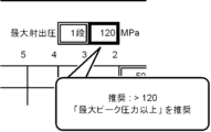
- FIG. 9 is a diagram showing an example of a display mode of information indicating the reason for recommending a change in molding conditions.
- the recommendation unit 104 displays on the display screen the character string "Recommendation: >120 Recommends 'maximum peak pressure or more'".
- the description "more than the maximum peak pressure” is the reason why changing the molding conditions is recommended.
- the condition presentation device may recommend molding conditions using setting criteria input by the user.
- FIG. 10 is a block diagram illustrating an example of the functions of a condition presentation device that includes an input reception unit that accepts input of setting criteria input by the user.
- the condition presentation device 10 shown in FIG. 10 differs from the condition presentation device 1 shown in FIG. 2 in that it includes an input reception unit 105, but is the same in other respects. Therefore, here, the input receiving section 105 will be explained, and the explanation of the other sections will be omitted.
- the input receiving unit 105 receives input of information indicating setting criteria. That is, the input accepting unit 105 accepts input of setting criteria defined by the user. In addition, the input receiving unit 105 may accept an input from a user for modifying the setting criteria stored in the setting criteria storage unit 103 in advance. This allows the user to input setting criteria created based on his or her own experience.
- one setting standard is provided for one setting item.
- a plurality of setting standards may be provided for one setting item.
- the setting criteria may include multiple criteria.
- the setting criteria may include multiple types of criteria.
- the plurality of criteria includes, for example, a first criterion for removing restrictions on molding data obtained when injection molding is performed, and a second criterion for stably molding a molded product by injection molding. , a third criterion for shortening the injection molding cycle time, and a fourth criterion for reducing the load on the injection molding machine. That is, a plurality of criteria among the first criterion, second criterion, third criterion, and fourth criterion may be provided for one setting item.
- the first criterion for removing restrictions on molding data obtained when injection molding is performed is, for example, if the maximum peak pressure is limited by the maximum injection pressure, This is a condition for cancellation.
- the second criterion for stably molding a molded product by injection molding is, for example, a criterion to prevent molding defects from occurring due to sudden changes in pressure during pressure holding or metering. That is, it is a setting standard set for the pressure of the second stage holding pressure. Further, the second standard is a setting standard for setting a reduced pressure in conditions related to metering.
- the third criterion for shortening the cycle time of injection molding is, for example, the criterion for setting the cooling time in the criterion regarding metering.
- the fourth criterion for reducing the load on the injection molding machine is, for example, the setting criterion for pre-metering pressure among the conditions related to holding pressure. That is, by using the pre-measurement pressure as a predetermined reference, sudden pressure changes in the injection molding machine, in other words, the load on the injection molding machine can be reduced.
- the plurality of criteria may include setting criteria accepted by the input reception unit 105.
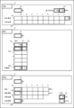
- FIG. 11 is a diagram for explaining an example in which a plurality of criteria are set for one setting item.
- three criteria are set as the criteria for setting the maximum injection pressure.
- the three criteria are, for example, conditional expression 1, conditional expression 2, and conditional expression 3.
- Conditional expression 1 is a function f with X1 and X2 as variables.
- the variables X1 and X2 are, for example, molding conditions or acquired data in setting items other than the maximum injection pressure.
- Conditional Expression 1 may be, for example, a criterion for stably molding a molded product.
- Conditional expression 2 is a function g with X1 as a variable.
- Conditional expression 2 may be a criterion for reducing the load on the injection molding machine, for example.
- Conditional expression 3 is a function h with X1 and X3 as variables.
- Conditional expression 3 may be, for example, a setting criterion accepted by the input accepting unit 105.
- condition presentation device may include a selection reception unit that accepts selection of setting criteria to be set for each setting item.
- FIG. 12 is a block diagram illustrating an example of the functions of a condition presentation device including a selection reception unit.
- the condition presentation device 20 shown in FIG. 12 differs from the condition presentation device 1 shown in FIG. 2 in that it includes a selection reception unit 106, but is the same in other respects. Therefore, here, the selection reception section 106 will be explained, and the explanation of the other sections will be omitted.
- the selection accepting unit 106 accepts selection of at least one of the multiple criteria.
- the selection accepting unit 106 accepts selections of setting criteria stored in the setting criteria storage unit 103.
- the selection reception unit 106 receives, for example, a selection of setting criteria to be set for each setting item via an input/output interface (not shown) included in the condition presentation device 20. That is, the user selects the setting criteria to be set for each setting item from the setting criteria stored in the setting criteria storage unit 103. Thereby, appropriate setting standards can be set for each setting item.
- the condition presentation device 20 may recommend changing the molding conditions in different display modes for each setting standard that has been set.
- FIG. 13 is a diagram for explaining an example in which a change in molding conditions is recommended in different display modes depending on the setting criteria set for each setting item.
- four setting standards the above-mentioned first standard, second standard, third standard, and fourth standard, are set for each setting item.
- the recommendation unit 104 determines whether or not to recommend changing the molding conditions based on a plurality of criteria, and if it is determined that changing the molding conditions is recommended, the recommendation unit 104 displays molding in different display modes for each of the plurality of criteria. Recommend changing conditions.
- the recommendation unit 104 determines whether the molding conditions set for the second-stage holding pressure satisfy each of the first condition, the second condition, the third condition, and the fourth condition. to judge. If the molding conditions set for the second-stage holding pressure satisfy the second, third, and fourth criteria but do not satisfy the first criterion, the recommendation unit 104 The color of the area 522 indicating the second-stage holding pressure is changed from white to red.
- the recommendation unit 104 sets the maximum injection pressure to the maximum injection pressure.
- the color of the displayed area 42 is changed from white to green.
- the recommendation unit 104 The color of the area 520 indicating pressure is changed from white to yellow.
- the recommendation unit 104 displays an area indicating the cooling time. Change the color of 65 from white to blue.
- priorities may be set for multiple criteria. For example, the first criterion may have the highest priority, the second criterion, the third criterion, and the fourth criterion may have lower priorities in this order.
- the molding conditions set for a certain setting item do not satisfy both the first criterion and the second criterion
- changing the molding conditions may be recommended based on the first criterion.
- the area 520 indicating the pressure before measurement is colored red based on the first criterion. Just change it.
- the recommendation unit 104 may display on a pop-up screen the basis on which the change in molding conditions is recommended. For example, when changing the molding conditions is recommended based on a first criterion with a high priority, the recommendation unit 104 may display a character string "first criterion" in a pop-up screen. This allows the user to understand based on which criteria a change in molding conditions is recommended.
Landscapes
- Engineering & Computer Science (AREA)
- Manufacturing & Machinery (AREA)
- Mechanical Engineering (AREA)
- Injection Moulding Of Plastics Or The Like (AREA)
Abstract
条件提示装置が、射出成形機における射出成形の成形条件を取得する取得部と、取得部が取得した成形条件および成形条件の設定基準に基づいて、成形条件に係る表示の表示態様を変更することにより、成形条件の変更を推奨する推奨部と、を備える。
Description
本開示は、条件提示装置、およびコンピュータ読み取り可能な記憶媒体に関する。
従来、エキスパートシステムを用いて、射出成形機における最適な成形条件を算出して提示する条件提示装置が知られている(例えば、特許文献1)。
しかし、このような装置は、互いに影響を及ぼし合う複数の成形条件の最適解を算出する。そのため、装置の構成が複雑となる。
そのため、簡易な構成でオペレータにとって操作性がよい条件提示装置が求められている。
条件提示装置が、射出成形機における射出成形の成形条件を取得する取得部と、取得部が取得した成形条件および成形条件の設定基準に基づいて、成形条件に係る表示の表示態様を変更することにより、成形条件の変更を推奨する推奨部と、を備える。
コンピュータ読み取り可能な記憶媒体が、射出成形機における射出成形の成形条件を取得することと、取得した成形条件および成形条件の設定基準に基づいて、成形条件に係る表示の表示態様を変更することにより、成形条件の変更を推奨することと、をコンピュータに実行させる命令を記憶する。
本開示の一態様により、簡易な構成でオペレータにとって操作性がよい条件提示装置を提供することができる。
以下、本開示の実施形態に係る条件提示装置について図面を用いて説明する。なお、以下の実施形態で説明する特徴のすべての組み合わせが課題解決に必ずしも必要であるとは限らない。また、必要以上の詳細な説明を省略する場合がある。また、以下の実施形態の説明、および図面は、当業者が本開示を十分に理解するために提供されるものであり、請求の範囲を限定することを意図していない。
条件提示装置は、射出成形機の成形条件を提示するための装置である。成形条件とは、射出成形機が成形品を成形するときの動作条件である。この動作条件には、例えば、最大射出圧、射出速度などが含まれる。具体的な成形条件については、後に詳しく説明する。
条件提示装置は、例えば、PC(Personal Computer)、またはサーバに実装される。条件提示装置は、射出成形機を制御する数値制御装置に実装されてもよい。以下では、条件提示装置がPCに実装された例について説明する。
図1は、条件提示装置のハードウェア構成の一例を示すブロック図である。条件提示装置1は、ハードウェアプロセッサ11と、バス12と、ROM(Read Only Memory)13と、RAM(Random Access Memory)14と、不揮発性メモリ15と、第1のインタフェース16と、第2のインタフェース17とを備える。
ハードウェアプロセッサ11は、システムプログラムに従って条件提示装置1全体を制御するプロセッサである。ハードウェアプロセッサ11は、バス12を介してROM13に格納されたシステムプログラムなどを読み出し、システムプログラムに基づいて各種処理を行う。ハードウェアプロセッサ11は、例えば、CPU(Central Processing Unit)、または電子回路である。
バス12は、条件提示装置1内の各ハードウェアを互いに接続する通信路である。条件提示装置1内の各ハードウェアはバス12を介してデータをやり取りする。
ROM13は、条件提示装置1全体を制御するためのシステムプログラムなどを記憶する記憶装置である。ROM13は、コンピュータ読み取り可能な記憶媒体である。
RAM14は、各種データを一時的に格納する記憶装置である。RAM14は、ハードウェアプロセッサ11が各種データを処理するための作業領域として機能する。
不揮発性メモリ15は、条件提示装置1の電源が切られ、条件提示装置1に電力が供給されていない状態でもデータを保持する記憶装置である。不揮発性メモリ15は、例えば、成形条件を記憶する。不揮発性メモリ15は、コンピュータ読み取り可能な記憶媒体である。不揮発性メモリ15は、例えば、バッテリでバックアップされたメモリ、または、SSD(Solid State Drive)で構成される。
第1のインタフェース16は、バス12と数値制御装置2とを接続する通信路である。例えば、ハードウェアプロセッサ11は、第1のインタフェース16を介して各種データを数値制御装置2に送る。また、数値制御装置2は、第1のインタフェース16を介して各種データを条件提示装置1に送る。
第2のインタフェース17は、バス12とセンサ3とを接続する通信路である。センサ3は、例えば、射出成形機の金型内部の圧力を検出するセンサ3である。例えば、不揮発性メモリ15は、センサ3から送られてきたデータを第2のインタフェース17を介して受けて記憶する。
図2は、条件提示装置1の機能の一例を示すブロック図である。条件提示装置1は、例えば、成形条件記憶部101と、取得部102と、設定基準記憶部103と、推奨部104とを備える。取得部102および推奨部104は、例えば、ハードウェアプロセッサ11が、ROM13に記憶されたシステムプログラム、ならびに、不揮発性メモリ15に記憶されている各種データを用いて演算処理することにより実現される。成形条件記憶部101および設定基準記憶部103は、例えば、外部機器から入力された成形条件および設定基準が不揮発性メモリ15に記憶されることにより実現される。
成形条件記憶部101は、成形条件を記憶する。成形条件とは、射出成形機において射出成形が行われるときの条件である。
成形条件は、例えば、射出に関する条件、保圧に関する条件、および計量に関する条件を含む。また、射出に関する条件、保圧に関する条件、および計量に関する条件は、それぞれ複数の設定項目を含む。
射出に関する条件の設定項目は、射出動作の段階数、最大射出圧、各段階における射出速度および切替位置を含む。射出動作の段階数とは、射出成形を何段階に分けて行うかを規定する項目である。切替位置とは、射出成形の各段階を切り替えるときのスクリューの位置を規定する項目である。
保圧に関する条件の設定項目は、保圧動作の段階数、各段階における圧力および時間を含む。保圧動作の段階数とは、保圧動作を何段階に分けて行うかを規定する項目である。
計量に関する条件の設定項目は、計量動作の段階数、各段階における背圧、回転速度および切替位置、冷却時間、ならびに減圧設定を含む。計量動作の段階数とは、計量動作を何段階に分けて行うかを規定する項目である。回転速度および切替位置とはそれぞれ、スクリューの回転速度および位置である。
条件提示装置1は、例えば、射出成形機に取り付けられる金型の種類に関連付けて記憶された金型ファイルから成形条件を取得して成形条件記憶部101に記憶させてよい。条件提示装置1は、例えば、オペレータからの成形条件の入力を受け付けて成形条件記憶部101に記憶させてもよい。
取得部102は、射出成形機における射出成形の成形条件を取得する。取得部102は、成形条件記憶部101に記憶された成形条件を取得する。条件提示装置1が成形条件記憶部101を備えていない場合、取得部102は、例えば、オペレータによって入力された成形条件を直接取得してよい。
図3は、取得部102によって取得された成形条件を表示する表示画面の一例を示す図である。表示画面は、射出に関する条件を示す表示領域4、保圧に関する条件を示す表示領域5、および計量に関する条件を示す表示領域6を含む。
射出に関する条件を示す表示領域4は、射出動作の段階数を示す領域41、最大射出圧を示す領域42、各段階における射出速度を示す領域43および各段階における切替位置を示す領域44を含む。図3に示す例では、射出動作の段階数が「1」、最大射出圧が「120」[MPa]、第1段階における射出速度が「50」[mm/s]に設定されている。
保圧に関する条件を示す表示領域5は、保圧動作の段階数を示す領域51、各段階における圧力を示す領域52および各段階の時間を示す領域53を含む。図3に示す例では、保圧動作の段階数が「2」、第1段階目の保圧の圧力が「100」[MPa]で「3」[秒]、第2段階目の保圧の圧力が「20」[MPa]で「3」[秒]、計量前の保圧の圧力が「20」[MPa]で「0.2」[秒]に設定されている。
計量に関する条件を示す領域6は、計量動作の段階数を示す領域61、各段階における背圧を示す領域62、各段階における回転速度を示す領域63および各段階間の切替位置を示す領域64、計量時における冷却時間を示す領域65、ならびに、減圧設定を示す領域66を含む。図3に示す例では、計量動作の段階数が「1」、計量時の背圧が「4」[MPa]、回転速度が「80」[min-1]、冷却時間が「20」[秒]、減圧設定が「20」[mm]で「2」[mm/s]に設定されている。ここで、図2の説明に戻る。
設定基準記憶部103は、成形条件の設定基準を記憶する。設定基準とは、成形条件の適切な数値、または適切な数値範囲であり、成形条件を設定する際の基準である。設定基準は、熟練した作業者の知恵、経験、ノウハウなどに基づいて決定される。また、設定基準は、成形条件の設定項目ごとに設けられる。
設定基準は、成形条件の推奨値、および成形条件の推奨範囲の少なくともいずれかであってよい。設定基準は、所定の計算式、および所定の条件式の少なくともいずれかであってもよい。所定の条件式は、例えば、射出成形が実行されるときに取得される成形データを利用した条件式である。成形データは、例えば、波形データ、工程データ、および外部センサデータである。
波形データは、射出成形機のセンサ3から取得される時系列データである。波形データは、例えば、射出成形機のノズルの圧力を示す時系列データ、射出速度を示す時系列データである。
工程データは、波形データの代表的な数値を示すデータや、成形1サイクルを通して得られる数値データである。代表的な数値は、例えば、波形データが示す時系列データの平均値、積算値、最大値、および最小値のいずれかであってよい。工程データは、例えば、ノズルの最大ピーク圧力、サイクルタイム、計量時間である。
外部センサデータは、射出成形機以外に設置されたセンサ3から取得されるデータである。外部センサデータは、例えば、金型に内蔵されたセンサ3によって取得されたデータである。
なお、設定基準は、機械学習を用いて決定してもよい。例えば、MLP(Multilayer perceptron)、重回帰分析を用いて設定基準を算出することができる。
図4は、成形データの一例を示す図である。成形データは、最大ピーク圧力、サイクルタイム、および計量時間を含む。
保圧に関する条件において、第n段階目の保圧の圧力は、第n-1段階目の保圧の圧力の40%以上、60%以下であることが望ましい。そのため、設定基準記憶部103は、例えば、第2段階目の保圧の圧力の設定基準として、「0.4x≦y≦0.6x」を記憶する。ただし、「y」は、第2段階目の保圧の圧力、「x」は、第1段階目の保圧の圧力である。
また、射出に関する条件において、最大射出圧は、センサ3によって取得される最大ピーク圧力以上である必要がある。仮に、最大射出圧が最大ピーク圧力と同じである場合、射出成形時における圧力が最大射出圧によって制限されていると考えられるからである。したがって、設定基準記憶部103は、最大射出圧の設定基準として、条件式「最大射出圧>最大ピーク圧力」を記憶する。
また、計量に関する条件において、減圧設定の距離に関する推奨値は、3[mm]である。したがって、設定基準記憶部103は、減圧設定の距離に関する設定基準として、数値3[mm]を記憶する。
また、保圧に関する条件において、計量前の圧力の値は、保圧の最終段階の圧力(図3に示す例では、第2段階目の圧力)と計量時の背圧との間の圧力変化が滑らかになるような値に設定される必要がある。したがって、図3に示す例において、設定基準記憶部103は、計量前圧力に関する設定基準として、例えば、数値「14」[MPa]を記憶する。なお、計量前の圧力に関する設定基準として、設定基準記憶部103は、保圧の最終段階の圧力と計量時の背圧とを考慮した所定の条件式を記憶してもよい。
また、計量に関する条件について、冷却時間は、通常、計量時間よりも十分長い時間に設定される(図4参照)。この場合、冷却時間を短くすると、サイクルタイムが短くなる可能性がある。つまり、既に成形された成形品の冷却のための冷却時間と新たな成形品の材料の計量が同時に開始され、両方が終了すると次の工程が開始される。
そのため、冷却時間および計量時間のうち、長い方を短くすることにより、全体のサイクルタイムが短くなる。そのため、設定基準記憶部103は、条件式「冷却時間≦計量時間+α」(ただし、α[秒]は、あらかじめ定められた時間)を記憶する。つまり、冷却時間がこの条件式を満たすように短く変更することができる。
推奨部104は、取得部102が取得した成形条件および成形条件の設定基準に基づいて、成形条件に係る表示の表示態様を変更することにより、成形条件の変更を推奨する。
また、推奨部104は、変更が推奨される成形条件とは異なる他の成形条件を変数とする条件式に基づいて成形条件の変更を推奨してもよい。
例えば、図3に示す例において、保圧に関する条件のうち、第1段階目の保圧の圧力が「100」[MPa]に設定されており、第2段階目の保圧の圧力が「20」[MPa]に設定されている。一方、設定基準記憶部103は、第2段階目の保圧の圧力の設定基準として「0.4x≦y≦0.6x」を記憶している。ここで、「y」は、第2段階目の保圧の圧力、「x」は、第1段階目の保圧の圧力である。また、第2段階目の保圧の圧力が、変更が推奨される成形条件であり、第1段階目の保圧の圧力他の成形条件である。
この場合、第2段階目の保圧の圧力として設定された成形条件は、設定基準を満たしていない。そのため、推奨部104は、保圧に関する条件のうち第2段階目の保圧の圧力の変更を推奨する。
図5は、推奨部104が成形条件の変更を推奨する表示画面の一例を示す図である。推奨部104は、例えば、第2段階目の保圧の圧力を示す領域522を白色から赤色に変更することにより、第2段階目の保圧の圧力の変更を推奨する。
推奨部104は、成形条件および設定基準、ならびに、射出成形が実行されるときに取得される成形データを変数とする条件式に基づいて、成形条件の変更を推奨してもよい。例えば、図3に示す例において、射出に関する条件のうち、最大射出圧が「120」[MPa]に設定されている。また、取得された最大ピーク圧力も、120[MPa]である(図4参照)。一方、設定基準記憶部103は、最大射出圧の設定基準として条件式「最大射出圧>最大ピーク圧力」を記憶している。つまり、最大射出圧は、設定基準を満たしていない。
そのため、推奨部104は、最大射出圧の変更を推奨する。推奨部104は、最大射出圧を示す領域42の色を白色から赤色に変更することにより、最大射出圧の変更をオペレータに推奨する(図5参照)。
また、図3に示す例において、計量に関する条件のうち、減圧設定が「20」[mm]に設定されている。一方、設定基準記憶部103は、減圧設定の設定基準として数値3[mm]を記憶している。
そのため、推奨部104は、減圧設定の変更を推奨する。推奨部104は、減圧設定を示す領域66の色を白色から赤色に変更することにより、減圧設定の変更をオペレータに推奨する(図5参照)。
また、図3に示す例において、保圧に関する条件のうち、計量前の圧力は、20[MPa]に設定されている。一方、設定基準記憶部103は、計量前の圧力の設定基準として14[MPa]を記憶している。
そのため、推奨部104は、計量前の圧力の変更を推奨する。推奨部104は、計量前の圧力を示す領域520の色を白色から赤色に変更することにより、計量前圧力の変更をオペレータに推奨する(図5参照)。
また、図3に示す例において、計量に関する条件のうち、冷却時間が20[秒]に設定されている。また、取得された計量時間は5[秒]である。一方、設定基準記憶部103は、冷却時間の設定基準として、条件式「冷却時間≦計量時間+α」を記憶する。例えば、αが12[秒]である場合、冷却時間は、この条件式を満たさない。
そのため、推奨部104は、冷却時間の変更を推奨する。推奨部104は、冷却時間を示す領域65の色を白色から赤色に変更することにより、冷却時間の変更をオペレータに推奨する(図5参照)。
成形条件の表示態様の変更は、成形条件を示す文字の色の変更、文字のスタイルの変更、文字の表示領域の色の変更、成形条件のアイコンの表示の変更、ならびに、文字および表示領域のうち少なくともいずれかの明度の変更のうちの少なくともいずれかであってよい。文字スタイルの変更は、例えば、フォントの変更、立体から斜体への変更、細字から太字への変更が含まれる。
アイコン表示の変更には、例えば、成形条件の変更に係る表示の近傍に、変更の推奨を表すアイコンを表示させることが含まれる。
推奨部104は、変更が推奨される設定項目を集約して表示することにより、成形条件の変更を推奨してもよい。
図6は、変更が推奨される設定項目を集約して表示する表示態様の一例を示す図である。推奨部104は、例えば、リンク、変更を推奨する設定項目、設定項目に設定されている成形条件の現在値、および推奨値を含む画像を表示画面に表示させる。
リンクとは、各設定項目が表示されている表示領域へのリンクである。つまり、右向きの矢印に対する操作を行うことにより、当該矢印に関連付けられた設定項目の表示領域へ移動することができる。例えば、「保圧-保圧2」のリンクに対する操作を行うことにより、第2段階目の保圧の圧力を示す領域522に移動することができる。
次に、条件提示装置1で実行される処理の流れについて説明する。
図7は、条件提示装置1で実行される処理の流れの一例を示すフローチャートである。条件提示装置1では、まず、取得部102が成形条件を取得する(ステップS1)。
次に、取得部102が、成形データを取得する(ステップS2)。すなわち、射出成形機が設定された成形条件に基づいて射出成形を行い、条件提示装置1が成形データを取得する。
最後に、推奨部104が、取得部102が取得した成形条件および成形条件の設定基準に基づいて、または、成形条件、設定基準、および成形データに基づいて、成形条件の変更を推奨して(ステップS3)、処理を終了する。
以上説明したように、条件提示装置1は、射出成形機における射出成形の成形条件を取得する取得部102と、取得部102が取得した成形条件および成形条件の設定基準に基づいて、成形条件に係る表示の表示態様を変更することにより、成形条件の変更を推奨する推奨部104と、を備える。また、推奨部104は、変更が推奨される成形条件とは異なる他の成形条件、および射出成形が実行されるときに取得される成形データの少なくともいずれかを変数とする条件式に基づいて成形条件の変更を推奨する。
そのため、簡易な構成でオペレータにとって操作性がよい条件提示装置1を提供することができる。具体的には、条件提示装置1は、数値、数値範囲、または単純な条件式で成形条件の評価を行うことができる。つまり、条件提示装置1は、複雑な評価式を用いることなく、オペレータに対して設定された成形条件を適切な成形条件に変更することを推奨することができる。
また、成形条件の表示態様の変更は、成形条件を示す文字の色の変更、文字のスタイルの変更、文字の表示領域の色の変更、成形条件のアイコンの表示の変更、ならびに、文字および表示領域のうち少なくともいずれかの明度の変更のうちの少なくともいずれかである。したがって、推奨部104は、確実にオペレータに対して成形条件の変更を推奨することができる。
上述した実施形態では、推奨部104は、成形条件の表示に係る表示の表示態様を変更することにより、成形条件の変更を推奨する。推奨部104は、さらに、推奨値、および推奨範囲の少なくともいずれかを提示してもよい。
図8は、推奨部104が、推奨値、および推奨範囲を提示する表示画面の一例を示す図である。推奨部104は、例えば、吹出し形状のポップアップ画面を用いて推奨値、または推奨範囲を表示画面に表示する。
例えば、推奨部104は、保圧に関する条件のうち、第2段階目の保圧の圧力を示す領域522に隣接する位置に現れるポップアップ画面中に、「推奨:40-60」との文字列を表示させる。すなわち、推奨部104は、第2段階目の保圧の圧力として40[MPa]以上、60[MPa]以下を推奨する。
また、推奨部104は、射出に関する条件のうち、最大射出圧を示す領域42に隣接する位置に現れるポップアップ画面中に、「推奨:>120」との文字列を表示させる。すなわち、推奨部104は、最大射出圧として120[MPa]よりも大きい圧力を推奨する。
また、推奨部104は、計量に関する条件のうち、減圧設定を示す領域66に隣接する位置に現れるポップアップ画面中に、「推奨:3」との文字列を表示させる。すなわち、推奨部104は、減圧設定の値として3[mm]を推奨する。
また、推奨部104は、保圧に関する条件のうち、計量前の圧力を示す領域520に隣接する位置に現れるポップアップ画面中に「推奨:14」との文字列を表示させる。すなわち、推奨部104は、計量前の圧力として14[MPa]を推奨する。
また、推奨部104は、計量に関する条件のうち、冷却時間を示す領域65に隣接する位置に現れるポップアップ画面中に、「推奨:<20」との文字列を表示させる。すなわち、推奨部104は、冷却時間として20[秒]未満の短い時間を推奨する。
条件提示装置1は、成形条件の変更を推奨する理由を示す情報を提示してもよい。
図9は、成形条件の変更を推奨する理由を示す情報の表示態様の一例を示す図である。上述したとおり、最大射出圧が最大ピーク圧力と同じである場合、最大射出圧は、最大ピーク圧力よりも大きい圧力に設定することが推奨させる。したがって、推奨部104は、「推奨:>120 「最大ピーク圧力以上」を推奨」との文字列を表示画面に表示させる。ここで、「最大ピーク圧力以上」との記述が成形条件の変更を推奨する理由である。
条件提示装置は、ユーザが入力する設定基準を用いて成形条件の推奨を行うようにしてもよい。
図10は、ユーザが入力する設定基準の入力を受け付ける入力受付部を備えた条件提示装置の機能の一例を示すブロック図である。図10に示す条件提示装置10は入力受付部105を備えている点で図2に示す条件提示装置1とは異なり、その他の点では一致する。したがって、ここでは、入力受付部105について説明し、その他各部についての説明は省略する。
入力受付部105は、設定基準を示す情報の入力を受け付ける。すなわち、入力受付部105は、ユーザが定義する設定基準の入力を受け付ける。また、入力受付部105は、あらかじめ設定基準記憶部103に記憶された設定基準を修正するためのユーザによる入力を受け付けてもよい。これにより、ユーザは、自らの経験に基づいて作成した設定基準を入力することができる。
上述した実施形態では、1つの設定項目に対して1つの設定基準が設けられている。しかし、1つの設定項目に対して複数の設定基準が設けられていてもよい。言い換えれば、設定基準が複数の基準を含んでいてもよい。さらに言い換えれば、設定基準は、複数の種別の基準を含んでいてもよい。
複数の基準は、例えば、射出成形が実行されるときに取得される成形データの制限を解除するための第1の基準、射出成形による成形品が安定して成形されるための第2の基準、射出成形のサイクルタイムを短縮するための第3の基準、および射出成形機に掛かる負荷を低減させる第4の基準の少なくともいずれかを含んでいてよい。すなわち、1つの設定項目に対しこれら第1の基準、第2の基準、第3の基準、および第4の基準のうち複数の基準が設けられていてもよい。
射出成形が実行されるときに取得される成形データの制限を解除するための第1の基準とは、例えば、最大射出圧によって最大ピーク圧力が制限されている場合に、最大ピーク圧力の制限を解除するための条件である。
射出成形による成形品が安定して成形されるための第2の基準は、例えば、保圧時または計量時に急激な圧力の変化により成形不良が起こらないようにするための基準である。すなわち、第2段階目の保圧の圧力について設定された設定基準である。また、第2の基準は、計量に関する条件における減圧設定の設定基準である。
射出成形のサイクルタイムを短縮するための第3の基準は、例えば、計量に関する基準における冷却時間の設定基準である。
射出成形機に掛かる負荷を低減させる第4の基準は、例えば、保圧に関する条件のうち、計量前圧力の設定基準である。すなわち、計量前圧力を所定の基準とすることにより、射出成形機における急激な圧力変化、言い換えれば、射出成形機に掛かる負荷を低減することができる。
また、複数の基準は、入力受付部105が受け付けた設定基準を含んでいてよい。図11は、1つの設定項目に複数の基準が設定される例を説明するための図である。図11に示す例では、最大射出圧の設定基準として3つの基準が設定されている。3つの基準は、例えば、条件式1、条件式2、および条件式3である。
条件式1は、X1、およびX2を変数とする関数fである。ここで、変数X1およびX2は、例えば、最大射出圧とは異なる他の設定項目における成形条件、または、取得データである。また、条件式1は、例えば、成形品が安定して成形されるための基準であってよい。
条件式2は、X1を変数とする関数gである。条件式2は、例えば、射出成形機に係る負荷を低減させるための基準であってよい。
条件式3は、X1、およびX3を変数とする関数hである。条件式3は、例えば、入力受付部105が受け付けた設定基準であってよい。
また、条件提示装置は、各設定項目に設定する設定基準の選択を受け付ける選択受付部を備えていてもよい。
図12は、選択受付部を備えた条件提示装置の機能の一例を示すブロック図である。図12に示す条件提示装置20は選択受付部106を備えている点で図2に示す条件提示装置1とは異なり、その他の点では一致する。したがって、ここでは、選択受付部106について説明し、その他各部についての説明は省略する。
選択受付部106は、複数の基準のうちの少なくとも1つの選択を受け付ける。選択受付部106は、設定基準記憶部103に記憶された設定基準の選択を受け付ける。選択受付部106は、例えば、条件提示装置20が有する入出力インタフェース(不図示)を介して、各設定項目に設定される設定基準の選択を受け付ける。つまり、ユーザは、設定基準記憶部103に記憶された設定基準から各設定項目に設定する設定基準を選択する。これにより、各設定項目に対して適切な設定基準を設定することができる。
条件提示装置20は、設定された設定基準ごとに異なる表示態様で成形条件の変更を推奨してもよい。
図13は、各設定項目に設定された設定基準ごとに異なる表示態様で成形条件の変更を推奨する例について説明するための図である。図13に示す例では、各設定項目にそれぞれ、上述した第1の基準、第2の基準、第3の基準および第4の基準の4つの設定基準が設定されている。
この場合、推奨部104は、複数の基準に基づいて成形条件の変更を推奨するか否かを判断し、成形条件の変更を推奨すると判断した場合、複数の基準ごとに互いに異なる表示態様で成形条件の変更を推奨する。
例えば、推奨部104は、第2段階目の保圧の圧力に設定された成形条件が第1の条件、第2の条件、第3の条件、および第4の条件のそれぞれを満たすか否かを判断する。第2段階目の保圧の圧力に設定された成形条件が、第2の基準、第3の基準、および第4の基準を満たすものの、第1の基準を満たさない場合、推奨部104は、第2段階目の保圧の圧力を示す領域522の色を白色から赤色に変更する。
また、最大射出圧に設定された成形条件が、第1の基準、第3の基準、および第4の基準を満たすものの、第2の基準を満たさない場合、推奨部104は、最大射出圧を示す領域42の色を白色から緑色に変更する。
また、計量前の圧力に設定された成形条件が、第1の基準、第2の基準、および第3の基準を満たすものの、第4の基準を満たさない場合、推奨部104は、計量前の圧力を示す領域520の色を白色から黄色に変更する。
また、冷却時間に設定された成形条件が、第1の基準、第2の基準、および第4の基準を満たすものの、第3の条件を満たさない場合、推奨部104は、冷却時間を示す領域65の色を白色から青色に変更する。
これにより、ユーザは、各設定項目の変更がどの基準に基づいて推奨されているのかを理解することができる。
また、複数の基準に優先度を設けてもよい。例えば、第1の基準の優先度が最も高く、第2の基準の優先度、第3の基準の優先度、第4の基準の優先度がこの順番で低くなるようにしてもよい。
この場合、ある設定項目に設定された成形条件が第1の基準、および第2の基準の両者を満たさない場合、第1の基準に基づいて成形条件の変更を推奨すればよい。具体的には、計量前の圧力に設定された成形条件が第1の基準および第2の基準を満たしていない場合、第1の基準に基づいて、計量前の圧力を示す領域520を赤色に変更すればよい。
さらに、推奨部104は、どの基準に基づいて成形条件の変更を推奨しているかをポップアップ画面中に表示してもよい。例えば、優先度の高い第1の基準に基づいて成形条件の変更が推奨される場合、推奨部104は、ポップアップ画面中に「第1の基準」との文字列を表示すればよい。これにより、ユーザは、どの基準に基づいて成形条件の変更が推奨されているかを理解することができる。
なお、本開示は上記実施の形態に限られたものではなく、趣旨を逸脱しない範囲で適宜変更することが可能である。例えば、本開示の実施の形態の任意の構成要素の変形、もしくは実施の形態の任意の構成要素の省略が可能である。
1 条件提示装置
10 条件提示装置
20 条件提示装置
11 ハードウェアプロセッサ
12 バス
13 ROM
14 RAM
15 不揮発性メモリ
16 第1のインタフェース
17 第2のインタフェース
101 成形条件記憶部
102 取得部
103 設定基準記憶部
104 推奨部
105 入力受付部
106 選択受付部
2 数値制御装置
3 センサ
4 射出に関する条件を示す表示領域
41 射出動作の段階数を示す領域
42 最大射出圧を示す領域
43 各段階における射出速度を示す領域
44 各段階における切替位置示す領域
5 保圧に関する条件を示す表示領域
51 保圧動作の段階数を示す領域
52 各段階における圧力を示す領域
520 計量前の圧力を示す領域
522 第2段階目の保圧の圧力を示す領域
53 各段階の時間を示す領域
6 計量に関する条件を示す表示領域
61 計量動作の段階数を示す領域
62 各段階における背圧を示す領域
63 各段階における回転速度を示す領域
64 各段階間の切替位置を示す領域
65 冷却時間を示す領域
66 減圧設定を示す領域
10 条件提示装置
20 条件提示装置
11 ハードウェアプロセッサ
12 バス
13 ROM
14 RAM
15 不揮発性メモリ
16 第1のインタフェース
17 第2のインタフェース
101 成形条件記憶部
102 取得部
103 設定基準記憶部
104 推奨部
105 入力受付部
106 選択受付部
2 数値制御装置
3 センサ
4 射出に関する条件を示す表示領域
41 射出動作の段階数を示す領域
42 最大射出圧を示す領域
43 各段階における射出速度を示す領域
44 各段階における切替位置示す領域
5 保圧に関する条件を示す表示領域
51 保圧動作の段階数を示す領域
52 各段階における圧力を示す領域
520 計量前の圧力を示す領域
522 第2段階目の保圧の圧力を示す領域
53 各段階の時間を示す領域
6 計量に関する条件を示す表示領域
61 計量動作の段階数を示す領域
62 各段階における背圧を示す領域
63 各段階における回転速度を示す領域
64 各段階間の切替位置を示す領域
65 冷却時間を示す領域
66 減圧設定を示す領域
Claims (11)
- 射出成形機における射出成形の成形条件を取得する取得部と、
前記取得部が取得した前記成形条件および前記成形条件の設定基準に基づいて、前記成形条件に係る表示の表示態様を変更することにより、前記成形条件の変更を推奨する推奨部と、
を備える条件提示装置。 - 前記成形条件の前記表示態様の変更は、前記成形条件を示す文字の色の変更、前記文字のスタイルの変更、前記文字の表示領域の色の変更、前記成形条件のアイコンの表示の変更、ならびに、前記文字および前記表示領域のうち少なくともいずれかの明度の変更のうちの少なくともいずれかである請求項1に記載の条件提示装置。
- 前記設定基準は、前記成形条件の推奨値、および前記成形条件の推奨範囲の少なくともいずれかを含み、
前記推奨部は、前記推奨値、および前記推奨範囲の少なくともいずれかを提示する請求項1または2に記載の条件提示装置。 - 前記設定基準は、複数の基準を含む請求項1~3のいずれか1項に記載の条件提示装置。
- 前記複数の基準は、前記射出成形が実行されるときに取得される成形データの制限を解除するための第1の基準、前記射出成形による成形品が安定して成形されるための第2の基準、前記射出成形のサイクルタイムを短縮するための第3の基準、および前記射出成形機に掛かる負荷を低減させる第4の基準の少なくともいずれかを含む請求項4に記載の条件提示装置。
- 前記複数の基準のうちの少なくとも1つの選択を受け付ける選択受付部をさらに備える請求項4または5に記載の条件提示装置。
- 前記推奨部は、前記複数の基準に基づいて前記成形条件の変更を推奨するか否かを判断し、
前記成形条件の変更を推奨すると判断した場合、前記推奨部は、前記複数の基準ごとに互いに異なる前記表示態様で前記成形条件の変更を推奨する請求項4~6のいずれか1項に記載の条件提示装置。 - 前記推奨部は、変更が推奨される前記成形条件とは異なる他の成形条件、および前記射出成形が実行されるときに取得される成形データの少なくともいずれかを変数とする条件式に基づいて前記成形条件の変更を推奨する請求項1~4のいずれか1項に記載の条件提示装置。
- 前記設定基準を示す情報の入力を受け付ける入力受付部をさらに備える請求項1~8のいずれか1項に記載の条件提示装置。
- 前記推奨部は、さらに、前記成形条件の変更を推奨する理由を示す情報を提示する請求項1~9のいずれか1項に記載の条件提示装置。
- 射出成形機における射出成形の成形条件を取得することと、
取得した前記成形条件および前記成形条件の設定基準に基づいて、前記成形条件に係る表示の表示態様を変更することにより、前記成形条件の変更を推奨することと、
をコンピュータに実行させる命令を記憶するコンピュータ読み取り可能な記憶媒体。
Priority Applications (2)
| Application Number | Priority Date | Filing Date | Title |
|---|---|---|---|
| PCT/JP2022/029694 WO2024028987A1 (ja) | 2022-08-02 | 2022-08-02 | 条件提示装置、およびコンピュータ読み取り可能な記憶媒体 |
| JP2024538574A JPWO2024028987A1 (ja) | 2022-08-02 | 2022-08-02 |
Applications Claiming Priority (1)
| Application Number | Priority Date | Filing Date | Title |
|---|---|---|---|
| PCT/JP2022/029694 WO2024028987A1 (ja) | 2022-08-02 | 2022-08-02 | 条件提示装置、およびコンピュータ読み取り可能な記憶媒体 |
Publications (1)
| Publication Number | Publication Date |
|---|---|
| WO2024028987A1 true WO2024028987A1 (ja) | 2024-02-08 |
Family
ID=89848713
Family Applications (1)
| Application Number | Title | Priority Date | Filing Date |
|---|---|---|---|
| PCT/JP2022/029694 Ceased WO2024028987A1 (ja) | 2022-08-02 | 2022-08-02 | 条件提示装置、およびコンピュータ読み取り可能な記憶媒体 |
Country Status (2)
| Country | Link |
|---|---|
| JP (1) | JPWO2024028987A1 (ja) |
| WO (1) | WO2024028987A1 (ja) |
Citations (2)
| Publication number | Priority date | Publication date | Assignee | Title |
|---|---|---|---|---|
| JP2021162978A (ja) * | 2020-03-31 | 2021-10-11 | 東レエンジニアリング株式会社 | 設計支援装置および設計支援方法 |
| JP2022066954A (ja) * | 2020-10-19 | 2022-05-02 | 株式会社日立製作所 | 射出成形支援システムおよび方法 |
-
2022
- 2022-08-02 WO PCT/JP2022/029694 patent/WO2024028987A1/ja not_active Ceased
- 2022-08-02 JP JP2024538574A patent/JPWO2024028987A1/ja active Pending
Patent Citations (2)
| Publication number | Priority date | Publication date | Assignee | Title |
|---|---|---|---|---|
| JP2021162978A (ja) * | 2020-03-31 | 2021-10-11 | 東レエンジニアリング株式会社 | 設計支援装置および設計支援方法 |
| JP2022066954A (ja) * | 2020-10-19 | 2022-05-02 | 株式会社日立製作所 | 射出成形支援システムおよび方法 |
Also Published As
| Publication number | Publication date |
|---|---|
| JPWO2024028987A1 (ja) | 2024-02-08 |
Similar Documents
| Publication | Publication Date | Title |
|---|---|---|
| US11513755B2 (en) | Display control device and display control method | |
| JP4109236B2 (ja) | 運転条件表示機能を有する射出成形機 | |
| JP2006021470A (ja) | 射出成形機のモニタリング装置及びモニタリング方法 | |
| JP4091613B2 (ja) | 射出成形機の画面表示制御装置 | |
| WO2024028987A1 (ja) | 条件提示装置、およびコンピュータ読み取り可能な記憶媒体 | |
| JP6412048B2 (ja) | 表示装置を備える射出成形機 | |
| JP6898296B2 (ja) | 射出成形機の表示装置 | |
| US20180345555A1 (en) | Industrial machine system and control method of industrial machine system | |
| US4961131A (en) | Programmable controller | |
| JP3680400B2 (ja) | グラフ表示装置及びグラフ表示制御方法 | |
| JP3020363B2 (ja) | 成形機のモニタ条件設定方法 | |
| JPH05274378A (ja) | 自動設計cadシステム | |
| JP4952824B2 (ja) | グラフ表示装置およびプログラム | |
| CN111324088B (zh) | 信息处理装置 | |
| JP2578280B2 (ja) | 成形機のコントローラ | |
| US10928984B2 (en) | Display device and display system of injection molding machine | |
| US7808380B1 (en) | Indicator processor | |
| JPWO2024028987A5 (ja) | ||
| JP4091631B2 (ja) | 機械の信号処理装置 | |
| WO2024004141A1 (ja) | 表示制御装置及び表示制御方法 | |
| CN115152141A (zh) | 选定装置及选定方法 | |
| JPH08152991A (ja) | 画面切替装置 | |
| JP3733104B2 (ja) | 射出成形機の設定値表示方法 | |
| JP6667647B2 (ja) | リモコン装置 | |
| KR100451804B1 (ko) | 모니터 색상 조정 회로 |
Legal Events
| Date | Code | Title | Description |
|---|---|---|---|
| 121 | Ep: the epo has been informed by wipo that ep was designated in this application |
Ref document number: 22953976 Country of ref document: EP Kind code of ref document: A1 |
|
| ENP | Entry into the national phase |
Ref document number: 2024538574 Country of ref document: JP Kind code of ref document: A |
|
| NENP | Non-entry into the national phase |
Ref country code: DE |
|
| 122 | Ep: pct application non-entry in european phase |
Ref document number: 22953976 Country of ref document: EP Kind code of ref document: A1 |