WO2024024930A1 - ニッケル酸化鉱石の湿式製錬方法 - Google Patents
ニッケル酸化鉱石の湿式製錬方法 Download PDFInfo
- Publication number
- WO2024024930A1 WO2024024930A1 PCT/JP2023/027703 JP2023027703W WO2024024930A1 WO 2024024930 A1 WO2024024930 A1 WO 2024024930A1 JP 2023027703 W JP2023027703 W JP 2023027703W WO 2024024930 A1 WO2024024930 A1 WO 2024024930A1
- Authority
- WO
- WIPO (PCT)
- Prior art keywords
- slurry
- leaching
- nickel
- neutralization
- nickel oxide
- Prior art date
- Legal status (The legal status is an assumption and is not a legal conclusion. Google has not performed a legal analysis and makes no representation as to the accuracy of the status listed.)
- Ceased
Links
Images


Classifications
-
- C—CHEMISTRY; METALLURGY
- C22—METALLURGY; FERROUS OR NON-FERROUS ALLOYS; TREATMENT OF ALLOYS OR NON-FERROUS METALS
- C22B—PRODUCTION AND REFINING OF METALS; PRETREATMENT OF RAW MATERIALS
- C22B23/00—Obtaining nickel or cobalt
-
- C—CHEMISTRY; METALLURGY
- C22—METALLURGY; FERROUS OR NON-FERROUS ALLOYS; TREATMENT OF ALLOYS OR NON-FERROUS METALS
- C22B—PRODUCTION AND REFINING OF METALS; PRETREATMENT OF RAW MATERIALS
- C22B3/00—Extraction of metal compounds from ores or concentrates by wet processes
- C22B3/04—Extraction of metal compounds from ores or concentrates by wet processes by leaching
- C22B3/06—Extraction of metal compounds from ores or concentrates by wet processes by leaching in inorganic acid solutions, e.g. with acids generated in situ; in inorganic salt solutions other than ammonium salt solutions
- C22B3/08—Sulfuric acid, other sulfurated acids or salts thereof
-
- C—CHEMISTRY; METALLURGY
- C22—METALLURGY; FERROUS OR NON-FERROUS ALLOYS; TREATMENT OF ALLOYS OR NON-FERROUS METALS
- C22B—PRODUCTION AND REFINING OF METALS; PRETREATMENT OF RAW MATERIALS
- C22B3/00—Extraction of metal compounds from ores or concentrates by wet processes
- C22B3/20—Treatment or purification of solutions, e.g. obtained by leaching
- C22B3/22—Treatment or purification of solutions, e.g. obtained by leaching by physical processes, e.g. by filtration, by magnetic means, or by thermal decomposition
-
- C—CHEMISTRY; METALLURGY
- C22—METALLURGY; FERROUS OR NON-FERROUS ALLOYS; TREATMENT OF ALLOYS OR NON-FERROUS METALS
- C22B—PRODUCTION AND REFINING OF METALS; PRETREATMENT OF RAW MATERIALS
- C22B3/00—Extraction of metal compounds from ores or concentrates by wet processes
- C22B3/20—Treatment or purification of solutions, e.g. obtained by leaching
- C22B3/44—Treatment or purification of solutions, e.g. obtained by leaching by chemical processes
-
- Y—GENERAL TAGGING OF NEW TECHNOLOGICAL DEVELOPMENTS; GENERAL TAGGING OF CROSS-SECTIONAL TECHNOLOGIES SPANNING OVER SEVERAL SECTIONS OF THE IPC; TECHNICAL SUBJECTS COVERED BY FORMER USPC CROSS-REFERENCE ART COLLECTIONS [XRACs] AND DIGESTS
- Y02—TECHNOLOGIES OR APPLICATIONS FOR MITIGATION OR ADAPTATION AGAINST CLIMATE CHANGE
- Y02P—CLIMATE CHANGE MITIGATION TECHNOLOGIES IN THE PRODUCTION OR PROCESSING OF GOODS
- Y02P10/00—Technologies related to metal processing
- Y02P10/20—Recycling
Definitions
- the present invention relates to a hydrometallurgical method for nickel oxide ore.
- HPAL process high pressure acid leaching method (hereinafter also referred to as "HPAL process”) using sulfuric acid has been attracting attention as a hydrometallurgical method for nickel oxide ore.
- This method differs from the conventional pyrometallurgy method, which is a general method for smelting nickel oxide ore, because it does not include dry processes such as reduction and drying processes, and is a process consisting of an integrated wet process. This will be advantageous in terms of target and cost. It also has the advantage that it is possible to obtain a nickel-containing sulfide with an improved nickel quality of about 50% by mass.
- nickel and cobalt are selectively recovered as sulfides, but most of the impurity elements such as iron, magnesium, manganese, and aluminum leached out in the leaching process are does not form sulfides and remains in the poor liquor after the sulfides are separated. In order to discharge this poor liquid, it is necessary to precipitate and remove the metal ions remaining in the poor liquid by neutralization treatment in the final neutralization step.
- Patent Document 1 describes a hydrometallurgical method based on high-temperature pressure leaching to recover nickel from nickel oxide ore, simplification of the leaching step and solid-liquid separation step, and the amount of neutralizing agent consumed and the amount of sediment in the neutralization step.
- a technique has been disclosed that provides a simple and highly efficient smelting method as a whole process by reducing the amount of smelting.
- Patent Document 1 does not disclose any technical idea regarding reducing the amount of sulfuric acid used for leaching treatment in the leaching process.
- hydrometallurgical smelting of nickel oxide ore it is naturally necessary to reduce the amount of neutralizing agent used without significantly reducing the actual yield of nickel. No solution has been disclosed.
- Patent Document 2 discloses that a preliminary neutralization step is performed in which a pH adjuster is added to the leaching slurry to adjust the pH within a predetermined range. It is considered that this makes it possible to reduce the amount of neutralizing agent used in the neutralization process performed downstream of the solid-liquid separation process to some extent.
- Patent Document 2 describes a specific neutralizing agent that makes it possible to reduce the amount of neutralizing agent used without reducing the actual yield of nickel when performing such a preliminary neutralization step. There is no mention of the type, composition, etc.
- the present invention was proposed in view of these circumstances, and provides a method for reducing the amount of neutralizing agent used without reducing the actual yield of nickel in a hydrometallurgical process for nickel oxide ore.
- the purpose is to provide
- the present inventors decided to perform a preliminary neutralization process in which a pH adjuster is added to the leaching slurry obtained in the leaching process to adjust the pH within a predetermined range.
- the inventors have discovered that the above-mentioned problems can be solved by using a "slurry for pre-neutralization treatment" whose nickel grade and magnesium grade are said to be higher than a predetermined grade as a neutralizing agent, and have completed the present invention. It's arrived. That is, the present invention provides the following.
- a hydrometallurgical method for nickel oxide ore comprising: a pre-neutralization step in which the pH adjuster has a magnesium content of 3% by weight or more in the solid content; A hydrometallurgical smelting method for nickel oxide ore using a pre-neutralization slurry having a nickel content of 0.7% or more in solid content.
- the amount of neutralizing agent used in the hydrometallurgical smelting process of nickel oxide ore, the amount of neutralizing agent used can be reduced without reducing the actual yield of nickel.
- a pretreatment step is performed prior to the leaching step, and includes a first separation step of separating the coarse particles using a spiral concentrator, and a second separation step of separating the coarse particles by specific gravity using a spiral concentrator.
- the invention (2) conventionally, although it is a part of the raw material ore and also contains a trace amount of nickel, it is not input into the leaching process as a part with a high proportion of gangue components and is used to produce the final product.
- the parts excluded from the line can be effectively used in the pre-neutralization process, and at that time, no special additional processing is required to adapt to the pre-neutralization process, so (1) invention can be implemented more economically.
- the amount of neutralizing agent used in the hydrometallurgical process of nickel oxide ore, can be reduced without reducing the actual yield of nickel. Accordingly, the productivity of the hydrometallurgical smelting process for nickel oxide ore can be improved.
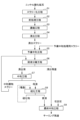
- FIG. 1 is an overall process diagram of a hydrometallurgical process that can be carried out using the hydrometallurgical smelting method for nickel oxide ore of the present invention.
- FIG. 1 is a schematic diagram showing the basic configuration of a spiral concentrator that can be used in the hydrometallurgical smelting method of nickel oxide ore of the present invention.
- 3 is a schematic diagram showing the basic configuration of a slurry separation fence provided at the end of a slurry flow path of the spiral concentrator shown in FIG. 2.
- FIG. 1 is an overall process diagram of a hydrometallurgical process that can be carried out using the hydrometallurgical smelting method for nickel oxide ore of the present invention.
- FIG. 1 is a schematic diagram showing the basic configuration of a spiral concentrator that can be used in the hydrometallurgical smelting method of nickel oxide ore of the present invention.
- 3 is a schematic diagram showing the basic configuration of a slurry separation fence provided at the end of a slurry flow path of the spiral concentrat
- FIG. 1 An example of the overall flow of the nickel oxide ore smelting process that can be carried out using the "nickel oxide ore hydrometallurgical method" of the present invention is shown in FIG. 1.
- This hydrometallurgical smelting process includes a slurrying step S1 in which nickel oxide ore is slurried to obtain a nickel oxide ore slurry, and a pretreatment to separate and remove gangue components from the nickel oxide ore slurry obtained in the slurry step S1.
- Treatment step S2 concentration step S3 of removing water contained in the nickel oxide ore slurry and concentrating ore components, adding sulfuric acid to the nickel oxide ore slurry that has gone through the pretreatment step S2 and concentration step S3 and leaching under high temperature and high pressure.
- a leaching step S4 in which a leaching slurry is obtained by performing a treatment
- a pre-neutralization step S5 in which a pH adjuster is added to the leaching slurry obtained in the leaching step S4, and a leaching slurry that has undergone the preliminary neutralization step S5 is converted into a leaching solution and a leaching residue.
- a solid-liquid separation step S6 in which the leachate obtained in the solid-liquid separation step S6 is separated, a neutralization step S7 in which a neutralized precipitate containing impurity elements is separated to obtain a neutralized final solution containing nickel;
- a sulfiding step S8 in which a sulfurizing agent is added to the neutralized final liquid obtained in the neutralizing step S7 to generate a nickel-containing sulfide, and a final neutralizing step S9 are sequentially performed.
- the "hydro-smelting method for nickel oxide ore" of the present invention includes at least the leaching step S4, the pre-neutralization step S5, the solidification step A method that requires liquid separation step S6, neutralization step S7, sulfurization step S8, and final neutralization step S9, and in addition, in the pre-neutralization step S5, the magnesium grade is determined based on unique knowledge.
- the main feature of this process is that a "pre-neutralization slurry" with specified nickel quality and nickel quality is used as a pH adjuster.
- the slurry process S1, pretreatment process S2, and concentration process S3 are normally performed in sequence as described above. However, each of these steps is not necessarily an essential step in the "method for hydrometallurgical smelting of nickel oxide ore" of the present invention. Regardless of whether each of these upstream steps (S1 to S3) is implemented or the implementation mode of each of these upstream steps (S1 to S3), the steps after the leaching step S4 in which the "nickel oxide ore slurry" is input. Any smelting process that is carried out in a manner that satisfies the requirements of the present invention falls within the technical scope of the present invention.
- Slurrying step S1 is a step of mixing nickel oxide ore with water to form a highly fluid nickel oxide ore slurry.
- ore slurry that is a mixture of nickel oxide ore and water is referred to as "nickel oxide ore slurry", but “nickel oxide ore slurry” may include any other material that does not impede the effects of the present invention.
- components other than nickel oxide ore and water may be contained.
- the nickel oxide ore used as the raw material ore in the slurrying step S1 is an ore containing nickel and cobalt, and so-called laterite ores such as limonite ore and saprolite ore are mainly used.
- the nickel content of laterite ore is generally 0.8% by weight or more and 2.5% by weight or less, and is contained as a hydroxide or a magnesium silicate mineral.
- the iron content is 10% by weight or more and 50% by weight or less, and is mainly in the form of trivalent hydroxide (goethite), but some divalent iron is contained in siliceous minerals.
- Ru In addition to such laterite ores, oxide ores containing valuable metals such as nickel, cobalt, manganese, and copper, such as manganese nodules existing in the deep seabed, are used.
- the pretreatment step S2 is a step of performing pretreatment to improve the nickel quality of the nickel oxide ore slurry by separating and removing gangue components from the "nickel oxide ore slurry" obtained in the slurrying step S1.
- gangue components such as iron, magnesium, manganese, and aluminum can be separated from the nickel oxide ore slurry before the treatment.
- the "nickel oxide ore slurry" obtained in the slurrying step S1 is processed into a coarse particle portion in which the proportion of particles having a particle size of less than 45 ⁇ m is 40% by mass or less in the solid content. (hereinafter also simply referred to as “coarse grain part”) and fine grain part; and the "coarse grain part” separated in this first separation step. It is preferable to use a processing method in which a second separation step in which specific gravity separation processing is further performed is performed sequentially. In such a treatment method that performs separation treatment in stages, the fine particle portion obtained in the first separation step and the heavy specific gravity portion collected in the heavy specific gravity portion side in the second separation step are transferred to the leaching step S4.
- the part containing a large amount of gangue components such as magnesium (light specific gravity part) that was not recovered in the heavy specific gravity part is removed from the "nickel oxide ore slurry" supplied to the leaching process S4. Separated and removed.
- the “first separation step” in which the ore slurry of nickel oxide ore is separated into the “coarse grain part” and the “fine grain part” as described above uses at least one of a hydrocyclone and a density separator. It can be carried out.
- This can be done using a "spiral concentrator.”
- a “spiral concentrator” is a separation device that includes a slurry flow path 11 that is a spiral inclined slide, like the spiral concentrator 1 shown in FIG.
- slurry separation fences 121 and 122 are installed at the end portion 12 of the slurry flow path 11, which is a region near the end of the slurry flow path 11. These two fences separate the spiral slurry flow path.
- slurry separation fences 121 and 122 are installed in a structure that allows their installation positions to be variably adjusted along the direction perpendicular to the flow direction of the slurry.
- the heavy specific gravity portion of the nickel oxide ore slurry is collected inside the first slurry separation fence and the second slurry separation fence.
- the other part (light specific gravity part) containing a large amount of gangue components such as magnesium is collected outside the second slurry separation fence (Tail part, hereinafter referred to as "Tail").
- the magnesium quality of the slurry (light specific gravity part) collected in the "tail" changes depending on the position of the slurry separation fence at the outlet of the spiral concentrator.
- the second slurry separation fence 122 is installed at a position where the width of the tail basin zone 125 is 30% or more of the total width of the slurry flow path.
- the magnesium content in the slurry (light specific gravity part) recovered is 3% or more.
- the amount of sulfuric acid used in the leaching process S4 and the amount of neutralizing agent used in the final neutralization process S9 can be effectively reduced. can be done.
- the concentration step S3 is a step in which the "nickel oxide ore slurry" that has undergone the pretreatment step S2 is concentrated by solid-liquid separation means such as a thickener (sedimentation separator). In this step, the "nickel oxide ore slurry" is concentrated to a solid content of 40% by mass or more. Thereby, the ore processing ability in the leaching step S4 can be further improved.
- leaching process In the leaching step S4, sulfuric acid is added to the "nickel oxide ore slurry" that has passed through the pretreatment step S2 and the concentration step S3, and the ore slurry is stirred while pressurized at a high temperature of 220°C to 280°C to form a leaching solution.
- This is a step of performing a leaching treatment to generate a leaching slurry consisting of a leaching residue.
- this leaching treatment can be performed by charging the above-mentioned "oxidized ore slurry" into a pressurized leaching reaction vessel such as an autoclave.
- nickel oxide ore also contains impurities such as iron, magnesium, manganese, and aluminum, and since these impurities are also leached out by sulfuric acid, this method is used to increase the actual yield of nickel and cobalt to be recovered. It is necessary to add an excessive amount of sulfuric acid to the leaching process. In particular, when ore with a high magnesium grade is input, the amount of sulfuric acid required increases, and the supply cannot keep up, resulting in a decrease in the nickel leaching rate. On the other hand, by sufficiently separating and removing gangue components from the "nickel oxide ore slurry" supplied to the leaching step S4 in the pretreatment step S2, the above-mentioned excessive use of sulfuric acid can be suppressed.
- Pre-neutralization step S5 is a step in which a pH adjuster is added to the leaching slurry obtained in leaching step S4 to neutralize free sulfuric acid.
- a pH adjuster is added to the leaching slurry obtained in leaching step S4 to neutralize free sulfuric acid.
- sulfuric acid in excess of the stoichiometric amount of sulfuric acid required for leaching valuable metals is usually introduced into the autoclave, so the leaching slurry contains excess sulfuric acid that did not participate in the leaching reaction. Contained in the form of residual free acid. Therefore, conventionally, in this preliminary neutralization step S5, the pH of the leaching slurry was adjusted to 2.5 to 3.4 by adding calcium carbonate slurry or the like as a pH adjusting agent.
- a "pre-neutralization treatment method” in which the magnesium grade and nickel grade are specified within a predetermined range based on unique knowledge is used as a pH adjuster.
- Slurry was used as a pH adjuster.
- this "pre-neutralization slurry” may have a magnesium content of 3% by weight or more in the solid content and a nickel content of 0.7% or more in the solid content.
- Stone (Mg,Fe) 3 Si 2 O 5 (OH) 4 ) can be mentioned.
- Serpentinite containing metal elements other than magnesium and iron is generally available at low cost, and also contains nickel and cobalt, which have properties similar to iron.
- Nickel and cobalt are also convenient as raw materials for obtaining sulfides containing nickel (and cobalt), which will be described later.
- serpentinites have a high magnesium content and some have a high nickel content, but they can be used in combination with other magnesium sources and nickel sources, if necessary.
- the slurry for pre-neutralization treatment after blending has a magnesium content of 3% by weight or more in the solid content and a nickel content of 0.7% or more in the solid content, thereby reducing waste while minimizing waste. , benefits such as savings in neutralizing agents and increased nickel recovery can be enjoyed.
- the preliminary neutralization treatment in the second separation step of the pretreatment step S2 the slurry separated and collected from the outer circumference of the spiral concentrator, that is, the slurry (light specific gravity part) collected in the "Tail" is used as the slurry for solid content.
- the magnesium content in the slurry is 3% by weight or more, and the nickel content in the solid content is 0.7% or more.
- the slurry can be directly fed into the preliminary neutralization step S5. can.
- the pretreatment step S2 is a treatment performed for the purpose of separating and removing various gangue components including magnesium from the nickel oxide ore slurry input to the leaching step S4. Even if the slurry is separated as a gangue component, if it contains nickel and magnesium above a specified value, it can be used as a pH adjuster to be added to the pre-neutralization process. It has been found that the effect of reducing the overall amount of sulfuric acid and neutralizing agent used is effective. By not introducing slurry with a high magnesium grade into the leaching step S4, it is expected that the amount of chemicals will be reduced, and the nickel leaching rate of the ore slurry will increase.
- the slurry (light specific gravity part) recovered in the "Tail” also contains nickel, so if the liquid is not sent to the leaching step S4, the nickel production amount will decrease accordingly.
- the magnesium oxide in the slurry (light specific gravity part) recovered in the above-mentioned "Tail” can be used as a pH adjuster (neutralizing agent), and nickel is leached out at that time.
- the Ni leaching rate in the pre-neutralization step S5 is lower than the leaching rate in the leaching step S4, a slurry in which the nickel content in the solid content is 0.7% or more is introduced into the pre-neutralization step S5.
- the total difference in profit and loss between the chemical reduction effect of the present invention and the nickel production amount in the existing mining area compared to normal operation is calculated based on the magnesium grade of the "pre-neutralization slurry" which is input as a pH adjuster into the pre-neutralization step S5.
- the research conducted by the present inventors has revealed that if the ratio is 3% or more, there will be an economical improvement.
- the solid-liquid separation step S6 is a step in which the leaching slurry that has undergone the preliminary neutralization step S5 is washed in multiple stages, and the leaching solution containing impurity elements in addition to nickel and cobalt is separated from the leaching residue.
- the solid-liquid separation step S6 can be performed, for example, by mixing the leaching slurry with the cleaning liquid and then performing solid-liquid separation treatment using solid-liquid separation equipment such as a thickener.
- the cleaning liquid cleaning water
- the cleaning liquid is not particularly limited, but it is preferable to use one that does not contain nickel and does not affect the process.
- the cleaning liquid preferably, the poor liquid obtained in the subsequent sulfurization step S8 can be repeatedly used.
- the neutralization step S7 is a step of adjusting the pH of the leachate separated in the solid-liquid separation step S6, separating the neutralized precipitate containing impurity elements, and obtaining a neutralized final solution containing nickel and cobalt. .
- the pH of the resulting neutralized final solution is 4 or less, preferably 3.0 to 3.5, more preferably 3.1 to 3.2, a neutralizing agent such as calcium carbonate is added to the leachate to produce a neutralized final solution and a neutralized precipitate slurry containing trivalent iron, aluminum, etc. as impurity elements.
- impurities are removed as a neutralized precipitate in this way, and a neutralized final liquid is generated which becomes a mother liquid for nickel recovery.
- the sulfiding step S8 is a step in which a sulfurizing agent is added to the mother liquor for nickel recovery to separate it into nickel sulfide and poor liquor.
- a sulfurizing agent such as hydrogen sulfide gas is blown into the neutralized final solution, which is a mother liquor for nickel recovery, to cause a sulfiding reaction, thereby producing sulfides containing nickel (and cobalt) (hereinafter simply " (also called nickel sulfide) and poor liquor.
- the neutralized final solution which is the mother liquor for nickel recovery
- this mother liquor for nickel recovery may contain several g/L of impurity components such as iron, magnesium, and manganese, but these impurity components have low stability as sulfides (recovery nickel and cobalt), they are not contained in the produced nickel sulfide.
- Nickel recovery equipment includes, for example, a sulfurization reaction tank that performs a sulfurization reaction by blowing hydrogen sulfide gas etc. into the neutralized final liquid, which is the mother liquid, and a solid-liquid separation tank that separates and recovers nickel sulfide from the liquid after the sulfurization reaction. Equipped with.
- the solid-liquid separation tank is composed of, for example, a thickener, and performs sedimentation separation treatment on the slurry containing nickel sulfide after the sulfurization reaction, thereby separating and recovering the nickel sulfide precipitate from the bottom of the thickener. .
- the aqueous solution component is allowed to overflow and is recovered as a poor solution.
- the recovered poor solution is a solution with an extremely low concentration of valuable metals such as nickel, and contains impurity elements such as iron, magnesium, and manganese that remain without being sulfurized. This poor liquid is transferred to the final neutralization step S9, which will be described later, and is rendered harmless.
- the final neutralization step S9 is a neutralization treatment (detoxification treatment) in which the poor liquid containing impurity elements such as iron, magnesium, and manganese discharged in the sulfurization step S8 is adjusted to a predetermined pH range that satisfies the discharge standards. ).
- the leaching residue discharged from the solid-liquid separation process in the solid-liquid separation step S6 can also be treated.
- the method of detoxification treatment in the final neutralization step S9 is not particularly limited, but may include, for example, adding a neutralizing agent such as calcium carbonate (limestone) slurry or calcium hydroxide (slaked lime) slurry. can be adjusted within a predetermined range.
- the "pre-neutralization step S5 performed on the upstream side, as described above, the "pre-neutralization By using “slurry” as a pH adjusting agent, the amount of neutralizing agent such as slaked lime used in the final neutralization step S9 can be reduced.
- impurity elements such as magnesium and manganese contained in the ore slurry can be reduced.
- concentration of these elements contained in the poor liquid can be reduced, and thereby also the amount of the neutralizing agent used for the neutralization treatment in the final neutralization step S9 can be reduced.
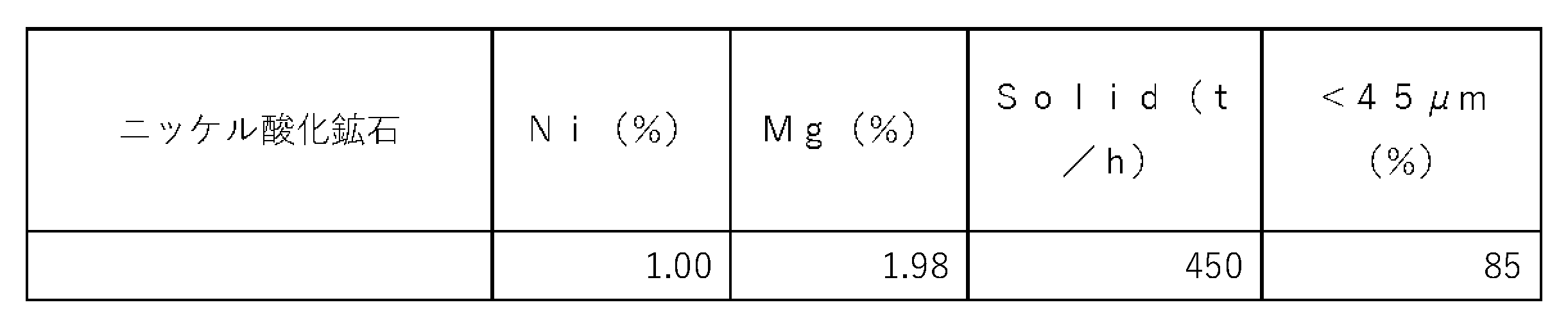
- Example 1 As shown below, nickel oxide ore was subjected to a hydrometallurgical process according to the process diagram shown in FIG. That is, first, as an ore slurry pretreatment step S2, a nickel oxide ore slurry obtained by slurrying nickel oxide ore having the composition shown in Table 1 below is subjected to a hydrocyclone (manufactured by Salter Cyclone, SC1030-P type). The underflow discharged from the hydrocyclone was then supplied to a density separator (manufactured by CS, 6 ⁇ 6 type) to undergo specific gravity separation. Note that these separation processing steps are referred to as a first separation step. Through the separation treatment in this first separation step, an ore slurry (coarse particle portion) was obtained in which the content of particles with a particle size of less than 45 ⁇ m in the underflow solid content of the density separator was 25% by mass.
- a hydrocyclone manufactured by Salter Cyclone, SC1030-P type
- the coarse ore slurry separated through the first separation step is prepared with a solid content concentration of 20%, and the width of the tail basin zone at the discharge port is 30% relative to the total width of the slurry flow path.
- % slurry separation fence slurry separation fence 122 in Figures 2 and 3
- An ore slurry containing solid content with a nickel grade of 0.86% and a magnesium grade of 3.2% as the slurry (hereinafter referred to as "Tail slurry") separated and recovered from the outer peripheral area (Tail basin zone). I got it. Note that this separation process is referred to as a second separation process.
- the ore slurry in the fine grain portion separated in the first separation step and the ore slurry in the heavy specific gravity portion separated in the second separation step were supplied to the leaching step.
- the above-mentioned "Tail slurry" obtained in the second separation step is used as a slurry for pre-neutralization treatment, and is subjected to the necessary pH adjustment to the target pH (approximately 3.1) in the pre-neutralization step. It was added to the pre-neutralization process as part of the agent.
- the reduction amount of sulfuric acid in the leaching process in which ore slurry was supplied and the reduction amount of slaked lime in the final neutralization step were 3.34t/Ni-t of sulfuric acid and 0.20t/Ni-t of slaked lime. became.
- the amount of Ni recovered in Table 2 indicates the ratio of the amount of recovered Ni when the amount of Ni recovered in the same operation in the existing mining area without separating and recovering "Tail Slurry" is set as 100. It is.
- Example 2 The same operation as in Example 1 was performed to obtain an ore slurry (coarse particle portion) in which the content of particles with a particle size of less than 45 ⁇ m in the underflow solid content of the density separator was 30% by mass in the first separation step. Ta.
- the coarse ore slurry separated through the first separation step is prepared with a solid content concentration of 20%, and the width of the tailing basin zone at the outlet is 40% relative to the total width of the slurry flow path.
- the slurry is supplied to a spiral concentrator (manufactured by Autotech) in which the position of the second slurry separation fence (slurry separation fence 122 in FIGS. 2 and 3) is adjusted so that the width of the slurry is 10%, and specific gravity separation is performed.
- An ore slurry containing solids with a grade of 0.88% and a magnesium grade of 4.1% was obtained. Note that this separation process is referred to as a second separation process.
- the ore slurry in the fine grain portion separated in the first separation step and the ore slurry in the heavy specific gravity portion separated in the second separation step were supplied to a leaching step in which the ore was subjected to leaching treatment.
- all of the above-mentioned "Tail slurry" obtained in the second separation step is used as a slurry for pre-neutralization treatment, and is adjusted to the required pH for the target pH (approximately 3.1) in the pre-neutralization step. It was added to the pre-neutralization step as part of the regulator.
- Example 3 The same operation as in Example 1 was performed to obtain an ore slurry (coarse particle portion) in which the content of particles with a particle size of less than 45 ⁇ m in the underflow solid content of the density separator was 35% by mass in the first separation step. Ta.
- the coarse ore slurry separated through the first separation step is prepared with a solid content concentration of 20%, and the width of the tail basin zone at the outlet is 50% relative to the total width of the slurry flow path.
- the slurry is supplied to a spiral concentrator (manufactured by Autotech Co., Ltd.) in which the position of the second slurry separation fence (slurry separation fence 122 in Figures 2 and 3) is adjusted so as to have a width of An ore slurry containing solids with a grade of 0.83% and a magnesium grade of 5.2% was obtained. Note that this separation process is referred to as a second separation process.
- the ore slurry in the fine grain portion separated in the first separation step and the ore slurry in the heavy specific gravity portion separated in the second separation step were supplied to a leaching step in which the ore was subjected to leaching treatment.
- all of the above-mentioned "Tail slurry" obtained in the second separation step is used as slurry for pre-neutralization treatment, and the pH is adjusted to the required pH for the target pH (approximately 3.1) in the pre-neutralization step. It was added to the pre-neutralization step as part of the regulator.
- the coarse ore slurry separated through the first separation step is prepared with a solid content concentration of 20%, and the width of the tail basin zone is 25% of the total width of the slurry channel.
- the slurry is supplied to a spiral concentrator (manufactured by Autotech) in which the position of the second slurry separation fence (slurry separation fence 122 in FIGS. 2 and 3) is adjusted so that specific gravity separation is performed, and the tail slurry has a nickel grade of 0.
- An ore slurry containing a solids content of .83% and a magnesium grade of 2.5% was obtained. Note that this separation process is referred to as a second separation process.
- the ore slurry in the fine grain portion separated in the first separation step and the ore slurry in the heavy specific gravity portion separated in the second separation step were supplied to a leaching step in which the ore was subjected to leaching treatment.
- all of the above-mentioned "Tail slurry" obtained in the second separation step is used as slurry for pre-neutralization treatment, and the pH is adjusted to the required pH for the target pH (approximately 3.1) in the pre-neutralization step. It was added to the pre-neutralization step as part of the regulator.
- the reduction amount of sulfuric acid in the leaching process in which ore slurry was supplied and the reduction amount of slaked lime in the final neutralization step were 2.26 t/Ni-t of sulfuric acid and 0.08 t/Ni-t of slaked lime.
- the amount of Ni recovered in the existing mining area will drop by more than 5%, resulting in an economic loss.
- Spiral concentrator 11 Slurry channel 12 End of slurry channel 121, 122 Slurry separation fence 123 Concentrate basin zone 124 Intermediate distribution basin zone 125 Tailing basin zone S1 Slurrying process S2 Pretreatment process S3 Concentration process S4 Leaching process S5 Preliminary Neutralization process S6 Solid-liquid separation process S7 Neutralization process S8 Sulfurization process S9 Final neutralization process
Landscapes
- Chemical & Material Sciences (AREA)
- Engineering & Computer Science (AREA)
- Metallurgy (AREA)
- Manufacturing & Machinery (AREA)
- Organic Chemistry (AREA)
- Mechanical Engineering (AREA)
- Materials Engineering (AREA)
- Geochemistry & Mineralogy (AREA)
- Geology (AREA)
- Life Sciences & Earth Sciences (AREA)
- General Life Sciences & Earth Sciences (AREA)
- Environmental & Geological Engineering (AREA)
- General Chemical & Material Sciences (AREA)
- Chemical Kinetics & Catalysis (AREA)
- Inorganic Chemistry (AREA)
- Manufacture And Refinement Of Metals (AREA)
Abstract
Description
本発明の「ニッケル酸化鉱石の湿式製錬方法」を用いて行うことができるニッケル酸化鉱石の製錬プロセスの全体工程としての流れは、一例として、図1に示す通りである。この湿式製錬プロセスは、ニッケル酸化鉱石をスラリー化してニッケル酸化鉱石スラリーを得るスラリー化工程S1、スラリー化工程S1で得たニッケル酸化鉱石スラリーから、脈石成分を分離除去する前処理を行う前処理工程S2、ニッケル酸化鉱石スラリーに含まれる水分を除去して鉱石成分を濃縮する濃縮工程S3、前処理工程S2及び濃縮工程S3を経たニッケル酸化鉱石スラリーに硫酸を添加して高温高圧下で浸出処理を施すことによって浸出スラリーを得る浸出工程S4、浸出工程S4で得た浸出スラリーにpH調整剤を添する予備中和工程S5、予備中和工程S5を経た浸出スラリーを、浸出液と浸出残渣とに分離する固液分離工程S6、固液分離工程S6で得た浸出液のpHを調整して不純物元素を含む中和澱物を分離してニッケルを含む中和終液を得る中和工程S7、中和工程S7で得た中和終液に硫化剤を添加することでニッケルを含む硫化物を生成させる硫化工程S8、及び、最終中和工程S9が順次行われるプロセスである。
スラリー化工程S1は、ニッケル酸化鉱石を水と混合して、流動性の高いニッケル酸化鉱石スラリーとする工程である。尚、本明細書においては、ニッケル酸化鉱石と水との混合物である鉱石スラリーのことを、「ニッケル酸化鉱石スラリー」と称するが、「ニッケル酸化鉱石スラリー」には、本発明の効果を阻害しない限りにおいて、ニッケル酸化鉱石及び水以外の成分が含有されていてもよい。
前処理工程S2は、スラリー化工程S1で得た「ニッケル酸化鉱石スラリー」から脈石成分を分離除去することによって、当該ニッケル酸化鉱石スラリーのニッケル品位を高める前処理を行う工程である。前処理工程S2において、上記の前処理をニッケル酸化鉱石スラリーに施すことによって、当該処理前のニッケル酸化鉱石スラリーから、鉄、マグネシウム、マンガン、アルミニウム等の脈石成分を分離することができる。
ニッケル酸化鉱石の鉱石スラリーを、上述したように「粗粒部」と、「細粒部」とに分離する「第1の分離工程」は、ハイドロサイクロン、デンシティセパレーターの少なくとも1つを使用して行うことができる。
第1の分離工程で分離した「粗粒部」から、ニッケルに対してマグネシウムの比率が大きく、比重の軽い脈石成分を選択的に除去する比重分離処理を更に行う「第2の分離工程」は、「スパイラルコンセントレーター」を用いて行うことができる。「スパイラルコンセントレーター」とは、図2に示すスパイラルコンセントレーター1のように、螺旋状の傾斜滑り台であるスラリー流路11を備える分離装置である。スラリー流路11の末端近傍域であるスラリー流路末端部12には、図3に示すようにスラリー分離柵121、122が設置されていて、これらの2つの柵により、螺旋状のスラリー流路11の内側から順に、濃縮物(Conc)流域帯123、中間物(Mids)流域帯124、テーリング(Tail)流域帯125の3つのスラリーの回収路が形成されている。尚、スラリー分離柵121、122はスラリーの流れ方向に直交する方向に沿ってその設置位置を可変的に調整することが可能な構造で設置されている。ニッケル酸化鉱石スラリーの重比重部は、第1のスラリー分離柵と第2のスラリー分離柵の内側に回収される。マグネシウム等の脈石成分を多く含むそれ以外の部分(軽比重部)は、は第2のスラリー分離柵の外側(Tail部分。以下「Tail」)に回収される。
濃縮工程S3は、前処理工程S2を経た「ニッケル酸化鉱石スラリー」を、シックナー(沈降分離装置)等の固液分離手段によって濃縮する工程である。この工程において、「ニッケル酸化鉱石スラリー」は、固形分40質量%以上に濃縮される。これにより、浸出工程S4での鉱石処理能力を更に向上させることができる。
浸出工程S4は、前処理工程S2及び濃縮工程S3を経た、「ニッケル酸化鉱石スラリー」に硫酸を添加し、220℃~280℃の高い温度条件下で加圧しながら鉱石スラリーを攪拌し、浸出液と浸出残渣とからなる浸出スラリーを生成させる浸出処理を行う工程である。この浸出処理は、具体的は、上記の「酸化鉱石スラリー」を、オートクレーブ等の加圧浸出反応容器に投入することによって行うことができる。
予備中和工程S5は、浸出工程S4で得た浸出スラリーにpH調整剤を添加して遊離硫酸を中和する工程である。浸出工程S4では、通常、有価金属の浸出に必要な硫酸の化学量論量よりも過剰の硫酸をオートクレーブに導入しているので、浸出スラリーには、浸出反応に関与しなかった余剰の硫酸が残留遊離酸の形態で含まれている。そこで、従来においては、この予備中和工程S5では、pH調整剤として炭酸カルシウムスラリー等を添加することによって浸出スラリーのpHを2.5~3.4に調整していた。
固液分離工程S6は、予備中和工程S5を経た浸出スラリーを、多段で洗浄しながら、ニッケル及びコバルトのほか不純物元素を含む浸出液と、浸出残渣とを分離する工程である。固液分離工程S6は、例えば、浸出スラリーを洗浄液と混合した後、シックナー等の固液分離設備により固液分離処理を施すことによって行うことができる。又、洗浄液(洗浄水)としては、特に限定されないが、ニッケルを含まず、工程に影響を及ぼさないものを用いることが好ましい。例えば、洗浄液として、好ましくは、後工程の硫化工程S8で得られる貧液を繰り返して利用することができる。
中和工程S7は、固液分離工程S6にて分離された浸出液のpHを調整し、不純物元素を含む中和澱物を分離して、ニッケルやコバルトを含む中和終液を得る工程である。具体的に、中和工程S7では、分離された浸出液の酸化を抑制しながら、得られる中和終液のpHが4以下、好ましくは3.0~3.5、より好ましくは3.1~3.2になるように、その浸出液に炭酸カルシウム等の中和剤を添加して、中和終液と不純物元素として3価の鉄やアルミニウム等を含む中和澱物スラリーとを生成させる。中和工程S7では、このようにして不純物を中和澱物として除去し、ニッケル回収用の母液となる中和終液を生成させる。
硫化工程S8は、上記のニッケル回収用の母液に硫化剤を添加して、ニッケル硫化物と貧液とに分離する工程である。硫化工程S8では、ニッケル回収用の母液である中和終液に対して、硫化水素ガス等の硫化剤を吹き込んで硫化反応を生じさせ、ニッケル(及びコバルト)を含む硫化物(以下、単に「ニッケル硫化物」ともいう)と貧液とを生成させる。
最終中和工程S9は、硫化工程S8にて排出された鉄、マグネシウム、マンガン等の不純物元素を含む貧液に対して、排出基準を満たす所定のpH範囲に調整する中和処理(無害化処理)を施す工程である。この最終中和工程S9では、固液分離工程S6における固液分離処理から排出された浸出残渣も併せて処理することもできる。最終中和工程S9における無害化処理の方法、即ち、pHの調整方法としては、特に限定されないが、例えば炭酸カルシウム(石灰石)スラリーや水酸化カルシウム(消石灰)スラリー等の中和剤を添加することによって所定の範囲に調整することができる。
以下に示すように、図1に示す工程図からなるニッケル酸化鉱石の湿式製錬処理を行った。即ち、先ず、鉱石スラリーの前処理工程S2として、下記表1に示す組成を有するニッケル酸化鉱石をスラリー化して得られたニッケル酸化鉱石スラリーを、ハイドロサイクロン(ソルターサイクロン社製,SC1030-P型)へ供給して分級分離処理を施し、続いて、ハイドロサイクロンから排出されたアンダーフローを、デンシティセパレーター(シーエフエス社製,6×6型)へ供給して比重分離処理を施した。尚、これらの分離処理の工程を第1の分離工程とする。この第1の分離工程における分離処理により、デンシティセパレーターのアンダーフロー固形分中における粒径45μm未満の粒子の含有量が25質量%である鉱石スラリー(粗粒部)を得た。
実施例1と同様の操作を行い、第1の分離工程において、デンシティセパレーターのアンダーフロー固形分中における粒径45μm未満の粒子の含有量が30質量%である鉱石スラリー(粗粒部)を得た。
実施例1と同様の操作を行い、第1の分離工程において、デンシティセパレーターのアンダーフロー固形分中における粒径45μm未満の粒子の含有量が35質量%である鉱石スラリー(粗粒部)を得た。
表1に組成を示したニッケル酸化鉱石をスラリー化し、実施例1と同様の操作を行い、第1の分離工程においてデンシティセパレーターのアンダーフロー固形分中における粒径45μm未満の粒子の含有量が25質量%である鉱石スラリー(粗粒部)を得た。
る消石灰使用量は低減できるものの、通常操業時との差損益が悪化した。
11 スラリー流路
12 スラリー流路末端部
121、122 スラリー分離柵
123 濃縮物流域帯
124 中間物流域帯
125 テーリング流域帯
S1 スラリー化工程
S2 前処理工程
S3 濃縮工程
S4 浸出工程
S5 予備中和工程
S6 固液分離工程
S7 中和工程
S8 硫化工程
S9 最終中和工程
Claims (2)
- ニッケル酸化鉱石スラリーに硫酸を添加して高温高圧下で浸出処理を施すことによって浸出スラリーを得る浸出工程と、
前記浸出スラリーにpH調整剤を添加する予備中和工程と、
前記予備中和工程を経た前記浸出スラリーを、浸出液と浸出残渣とに分離する固液分離工程と、
前記浸出液のpHを調整してニッケルを含む中和終液を得る中和工程と、
前記中和終液に硫化剤を添加することでニッケルを含む硫化物を生成させる硫化工程と、
前記硫化工程から排出された貧液を回収して無害化する最終中和工程と、
を含んでなる、ニッケル酸化鉱石の湿式製錬方法であって、
前記予備中和工程においては、前記pH調整剤として、固形分中のマグネシウム含有量が3重量%以上であり、固形分中のニッケル含有量が0.7%以上である、予備中和処理用スラリーを用いる、
ニッケル酸化鉱石の湿式製錬方法。 - ハイドロサイクロン及び/又はデンシティセパレーターを利用して、水分を加えてスラリー化した前記ニッケル酸化鉱石から、粒径が45μm以下の粒子の割合が40重量%以下である粗粒部を分離回収する第1の分離工程と、前記粗粒部をスパイラルコンセントレーターによって比重分離する第2の分離工程と、を含んでなる前処理工程が、前記浸出工程に先行して行われ、
前記予備中和処理用スラリーは、
前記前処理工程において、前記スパイラルコンセントレーターの外周部から分離回収されたスラリーである、
請求項1に記載のニッケル酸化鉱石の湿式製錬方法。
Priority Applications (1)
| Application Number | Priority Date | Filing Date | Title |
|---|---|---|---|
| AU2023316176A AU2023316176B2 (en) | 2022-07-28 | 2023-07-28 | Hydrometallurgical method for nickel oxide ore |
Applications Claiming Priority (2)
| Application Number | Priority Date | Filing Date | Title |
|---|---|---|---|
| JP2022-120949 | 2022-07-28 | ||
| JP2022120949A JP7273269B1 (ja) | 2022-07-28 | 2022-07-28 | ニッケル酸化鉱石の湿式製錬方法 |
Publications (1)
| Publication Number | Publication Date |
|---|---|
| WO2024024930A1 true WO2024024930A1 (ja) | 2024-02-01 |
Family
ID=86321998
Family Applications (1)
| Application Number | Title | Priority Date | Filing Date |
|---|---|---|---|
| PCT/JP2023/027703 Ceased WO2024024930A1 (ja) | 2022-07-28 | 2023-07-28 | ニッケル酸化鉱石の湿式製錬方法 |
Country Status (3)
| Country | Link |
|---|---|
| JP (2) | JP7273269B1 (ja) |
| AU (1) | AU2023316176B2 (ja) |
| WO (1) | WO2024024930A1 (ja) |
Citations (10)
| Publication number | Priority date | Publication date | Assignee | Title |
|---|---|---|---|---|
| WO2005098061A1 (ja) * | 2004-03-31 | 2005-10-20 | Pacific Metals Co., Ltd. | ニッケルまたはコバルトの浸出方法および回収方法 |
| JP2007077459A (ja) * | 2005-09-15 | 2007-03-29 | Taiheiyo Kinzoku Kk | ニッケルまたはコバルトの回収方法 |
| JP2013095971A (ja) * | 2011-11-01 | 2013-05-20 | Sumitomo Metal Mining Co Ltd | ニッケル酸化鉱石の湿式製錬方法 |
| JP2015000835A (ja) * | 2013-06-17 | 2015-01-05 | 住友金属鉱山株式会社 | ヘマタイトの製造方法、並びにそのヘマタイト |
| JP2019065341A (ja) * | 2017-09-29 | 2019-04-25 | 住友金属鉱山株式会社 | ニッケル酸化鉱石の湿式製錬方法 |
| JP2020028858A (ja) * | 2018-08-23 | 2020-02-27 | 住友金属鉱山株式会社 | ニッケル酸化鉱石の湿式製錬プロセスにおける最終中和方法 |
| JP2020076129A (ja) * | 2018-11-08 | 2020-05-21 | 住友金属鉱山株式会社 | 石膏スケールの析出を抑制したニッケル酸化鉱石の湿式製錬方法 |
| JP2020158819A (ja) * | 2019-03-26 | 2020-10-01 | 住友金属鉱山株式会社 | 水酸化ニッケルの精製方法 |
| JP2021008654A (ja) * | 2019-07-02 | 2021-01-28 | 住友金属鉱山株式会社 | ニッケル酸化鉱石の浸出処理方法及びこれを含む湿式製錬方法 |
| JP2021030101A (ja) * | 2019-08-15 | 2021-03-01 | 住友金属鉱山株式会社 | 中和処理方法 |
Family Cites Families (5)
| Publication number | Priority date | Publication date | Assignee | Title |
|---|---|---|---|---|
| GB2001612B (en) * | 1977-08-01 | 1982-05-26 | Amax Inc | Leaching nickeliferous oxide ores |
| US6379636B2 (en) * | 1999-11-03 | 2002-04-30 | Bhp Minerals International, Inc. | Method for leaching nickeliferous laterite ores |
| BRPI0505976B8 (pt) * | 2004-03-31 | 2016-05-24 | Pacific Metals Co Ltd | processo para recuperar níquel ou cobalto |
| JP2019203161A (ja) * | 2018-05-22 | 2019-11-28 | 住友金属鉱山株式会社 | フラッシュベッセルの運転方法 |
| JP7220846B2 (ja) * | 2019-04-24 | 2023-02-13 | 住友金属鉱山株式会社 | 湿式製錬の原料として使用されるニッケル酸化鉱石の前処理方法 |
-
2022
- 2022-07-28 JP JP2022120949A patent/JP7273269B1/ja active Active
-
2023
- 2023-04-13 JP JP2023065972A patent/JP2024018929A/ja active Pending
- 2023-07-28 WO PCT/JP2023/027703 patent/WO2024024930A1/ja not_active Ceased
- 2023-07-28 AU AU2023316176A patent/AU2023316176B2/en active Active
Patent Citations (10)
| Publication number | Priority date | Publication date | Assignee | Title |
|---|---|---|---|---|
| WO2005098061A1 (ja) * | 2004-03-31 | 2005-10-20 | Pacific Metals Co., Ltd. | ニッケルまたはコバルトの浸出方法および回収方法 |
| JP2007077459A (ja) * | 2005-09-15 | 2007-03-29 | Taiheiyo Kinzoku Kk | ニッケルまたはコバルトの回収方法 |
| JP2013095971A (ja) * | 2011-11-01 | 2013-05-20 | Sumitomo Metal Mining Co Ltd | ニッケル酸化鉱石の湿式製錬方法 |
| JP2015000835A (ja) * | 2013-06-17 | 2015-01-05 | 住友金属鉱山株式会社 | ヘマタイトの製造方法、並びにそのヘマタイト |
| JP2019065341A (ja) * | 2017-09-29 | 2019-04-25 | 住友金属鉱山株式会社 | ニッケル酸化鉱石の湿式製錬方法 |
| JP2020028858A (ja) * | 2018-08-23 | 2020-02-27 | 住友金属鉱山株式会社 | ニッケル酸化鉱石の湿式製錬プロセスにおける最終中和方法 |
| JP2020076129A (ja) * | 2018-11-08 | 2020-05-21 | 住友金属鉱山株式会社 | 石膏スケールの析出を抑制したニッケル酸化鉱石の湿式製錬方法 |
| JP2020158819A (ja) * | 2019-03-26 | 2020-10-01 | 住友金属鉱山株式会社 | 水酸化ニッケルの精製方法 |
| JP2021008654A (ja) * | 2019-07-02 | 2021-01-28 | 住友金属鉱山株式会社 | ニッケル酸化鉱石の浸出処理方法及びこれを含む湿式製錬方法 |
| JP2021030101A (ja) * | 2019-08-15 | 2021-03-01 | 住友金属鉱山株式会社 | 中和処理方法 |
Also Published As
| Publication number | Publication date |
|---|---|
| JP2024017958A (ja) | 2024-02-08 |
| JP7273269B1 (ja) | 2023-05-15 |
| AU2023316176B2 (en) | 2026-02-26 |
| JP2024018929A (ja) | 2024-02-08 |
| AU2023316176A1 (en) | 2025-02-20 |
Similar Documents
| Publication | Publication Date | Title |
|---|---|---|
| JP5757442B2 (ja) | ニッケル酸化鉱石の湿式製錬方法 | |
| JP6183788B2 (ja) | ニッケル酸化鉱石の湿式製錬方法 | |
| JP5403033B2 (ja) | ニッケル酸化鉱石の湿式製錬方法 | |
| EP2910655B1 (en) | Wet-mode nickel oxide ore smelting method | |
| JP6661926B2 (ja) | 鉱石スラリーの処理方法、ニッケル酸化鉱石の湿式製錬方法 | |
| JP2015206068A5 (ja) | ||
| EP3296410B1 (en) | Mineral ore slurry pretreatment method, and method for manufacturing mineral ore slurry | |
| EP3252176B1 (en) | Ore slurry pre-treatment method and ore slurry manufacturing method | |
| JP6969262B2 (ja) | ニッケル酸化鉱石の湿式製錬方法 | |
| JP2020028858A (ja) | ニッケル酸化鉱石の湿式製錬プロセスにおける最終中和方法 | |
| JP6977458B2 (ja) | ニッケル酸化鉱石の湿式製錬方法 | |
| JP7273269B1 (ja) | ニッケル酸化鉱石の湿式製錬方法 | |
| WO2021193424A1 (ja) | 鉱石スラリーの処理方法、ニッケル酸化鉱石の湿式製錬方法 | |
| CN103314124A (zh) | 从具有低镍含量的材料分离镍的方法 |
Legal Events
| Date | Code | Title | Description |
|---|---|---|---|
| 121 | Ep: the epo has been informed by wipo that ep was designated in this application |
Ref document number: 23846660 Country of ref document: EP Kind code of ref document: A1 |
|
| WWE | Wipo information: entry into national phase |
Ref document number: AU2023316176 Country of ref document: AU |
|
| ENP | Entry into the national phase |
Ref document number: 2023316176 Country of ref document: AU Date of ref document: 20230728 Kind code of ref document: A |
|
| NENP | Non-entry into the national phase |
Ref country code: DE |
|
| 122 | Ep: pct application non-entry in european phase |
Ref document number: 23846660 Country of ref document: EP Kind code of ref document: A1 |