WO2024024796A1 - 画像管理システム、サンプル選択方法、画像管理装置、画像表示装置、及びプログラム - Google Patents
画像管理システム、サンプル選択方法、画像管理装置、画像表示装置、及びプログラム Download PDFInfo
- Publication number
- WO2024024796A1 WO2024024796A1 PCT/JP2023/027237 JP2023027237W WO2024024796A1 WO 2024024796 A1 WO2024024796 A1 WO 2024024796A1 JP 2023027237 W JP2023027237 W JP 2023027237W WO 2024024796 A1 WO2024024796 A1 WO 2024024796A1
- Authority
- WO
- WIPO (PCT)
- Prior art keywords
- image
- information
- sample
- selection
- area
- Prior art date
Links
- 238000010187 selection method Methods 0.000 title claims abstract description 8
- LFEUVBZXUFMACD-UHFFFAOYSA-H lead(2+);trioxido(oxo)-$l^{5}-arsane Chemical compound [Pb+2].[Pb+2].[Pb+2].[O-][As]([O-])([O-])=O.[O-][As]([O-])([O-])=O LFEUVBZXUFMACD-UHFFFAOYSA-H 0.000 claims abstract description 64
- 238000003860 storage Methods 0.000 claims abstract description 56
- 238000000034 method Methods 0.000 claims description 42
- 239000000835 fiber Substances 0.000 claims description 32
- 238000005520 cutting process Methods 0.000 claims description 22
- 230000006870 function Effects 0.000 claims description 15
- 238000010191 image analysis Methods 0.000 claims description 10
- 238000003384 imaging method Methods 0.000 abstract description 41
- 238000013441 quality evaluation Methods 0.000 abstract description 10
- 238000011156 evaluation Methods 0.000 description 33
- 238000012545 processing Methods 0.000 description 23
- 239000000463 material Substances 0.000 description 16
- 239000011347 resin Substances 0.000 description 15
- 229920005989 resin Polymers 0.000 description 15
- 238000012360 testing method Methods 0.000 description 15
- 239000002131 composite material Substances 0.000 description 11
- 239000000945 filler Substances 0.000 description 9
- 239000004918 carbon fiber reinforced polymer Substances 0.000 description 7
- 238000004891 communication Methods 0.000 description 7
- 238000010586 diagram Methods 0.000 description 7
- 238000000605 extraction Methods 0.000 description 7
- 238000000465 moulding Methods 0.000 description 7
- 230000003287 optical effect Effects 0.000 description 7
- 239000000284 extract Substances 0.000 description 6
- 238000005259 measurement Methods 0.000 description 5
- 239000004033 plastic Substances 0.000 description 5
- 229920003023 plastic Polymers 0.000 description 5
- 239000000126 substance Substances 0.000 description 5
- 238000010521 absorption reaction Methods 0.000 description 4
- 229920000049 Carbon (fiber) Polymers 0.000 description 2
- 229920002430 Fibre-reinforced plastic Polymers 0.000 description 2
- 238000004458 analytical method Methods 0.000 description 2
- 238000005452 bending Methods 0.000 description 2
- 238000004364 calculation method Methods 0.000 description 2
- 239000004917 carbon fiber Substances 0.000 description 2
- 230000007547 defect Effects 0.000 description 2
- 238000001514 detection method Methods 0.000 description 2
- 230000000694 effects Effects 0.000 description 2
- 229920006351 engineering plastic Polymers 0.000 description 2
- 239000011151 fibre-reinforced plastic Substances 0.000 description 2
- 239000011152 fibreglass Substances 0.000 description 2
- 238000009863 impact test Methods 0.000 description 2
- 238000007689 inspection Methods 0.000 description 2
- 230000001678 irradiating effect Effects 0.000 description 2
- 239000011156 metal matrix composite Substances 0.000 description 2
- 238000003825 pressing Methods 0.000 description 2
- 238000000513 principal component analysis Methods 0.000 description 2
- 239000004065 semiconductor Substances 0.000 description 2
- 239000000454 talc Substances 0.000 description 2
- 229910052623 talc Inorganic materials 0.000 description 2
- 238000009864 tensile test Methods 0.000 description 2
- 229920003043 Cellulose fiber Polymers 0.000 description 1
- 239000004677 Nylon Substances 0.000 description 1
- 239000012790 adhesive layer Substances 0.000 description 1
- 239000004760 aramid Substances 0.000 description 1
- 229920006231 aramid fiber Polymers 0.000 description 1
- 230000005540 biological transmission Effects 0.000 description 1
- 239000000919 ceramic Substances 0.000 description 1
- 239000011153 ceramic matrix composite Substances 0.000 description 1
- 238000006243 chemical reaction Methods 0.000 description 1
- KPLQYGBQNPPQGA-UHFFFAOYSA-N cobalt samarium Chemical compound [Co].[Sm] KPLQYGBQNPPQGA-UHFFFAOYSA-N 0.000 description 1
- 239000003086 colorant Substances 0.000 description 1
- 239000000805 composite resin Substances 0.000 description 1
- 239000004567 concrete Substances 0.000 description 1
- 238000001816 cooling Methods 0.000 description 1
- 230000007423 decrease Effects 0.000 description 1
- -1 density unevenness Substances 0.000 description 1
- 238000013461 design Methods 0.000 description 1
- 238000011161 development Methods 0.000 description 1
- 238000009826 distribution Methods 0.000 description 1
- 238000009408 flooring Methods 0.000 description 1
- 239000003365 glass fiber Substances 0.000 description 1
- 230000005484 gravity Effects 0.000 description 1
- 230000001939 inductive effect Effects 0.000 description 1
- 238000002347 injection Methods 0.000 description 1
- 239000007924 injection Substances 0.000 description 1
- 238000001746 injection moulding Methods 0.000 description 1
- 229910010272 inorganic material Inorganic materials 0.000 description 1
- 239000011147 inorganic material Substances 0.000 description 1
- 238000004898 kneading Methods 0.000 description 1
- 239000004973 liquid crystal related substance Substances 0.000 description 1
- 239000000696 magnetic material Substances 0.000 description 1
- 229910052751 metal Inorganic materials 0.000 description 1
- 239000002184 metal Substances 0.000 description 1
- 239000007769 metal material Substances 0.000 description 1
- 150000002739 metals Chemical class 0.000 description 1
- 239000002105 nanoparticle Substances 0.000 description 1
- 229920001778 nylon Polymers 0.000 description 1
- 239000011368 organic material Substances 0.000 description 1
- 230000000704 physical effect Effects 0.000 description 1
- 239000011120 plywood Substances 0.000 description 1
- 230000000644 propagated effect Effects 0.000 description 1
- 230000001902 propagating effect Effects 0.000 description 1
- 239000011150 reinforced concrete Substances 0.000 description 1
- 230000002787 reinforcement Effects 0.000 description 1
- 239000012783 reinforcing fiber Substances 0.000 description 1
- 229910000938 samarium–cobalt magnet Inorganic materials 0.000 description 1
- 229910052712 strontium Inorganic materials 0.000 description 1
- CIOAGBVUUVVLOB-UHFFFAOYSA-N strontium atom Chemical compound [Sr] CIOAGBVUUVVLOB-UHFFFAOYSA-N 0.000 description 1
- 229920001169 thermoplastic Polymers 0.000 description 1
- 239000004416 thermosoftening plastic Substances 0.000 description 1
- 239000002023 wood Substances 0.000 description 1
- 229910000859 α-Fe Inorganic materials 0.000 description 1
Images


Classifications
-
- G—PHYSICS
- G01—MEASURING; TESTING
- G01N—INVESTIGATING OR ANALYSING MATERIALS BY DETERMINING THEIR CHEMICAL OR PHYSICAL PROPERTIES
- G01N23/00—Investigating or analysing materials by the use of wave or particle radiation, e.g. X-rays or neutrons, not covered by groups G01N3/00 – G01N17/00, G01N21/00 or G01N22/00
- G01N23/02—Investigating or analysing materials by the use of wave or particle radiation, e.g. X-rays or neutrons, not covered by groups G01N3/00 – G01N17/00, G01N21/00 or G01N22/00 by transmitting the radiation through the material
- G01N23/04—Investigating or analysing materials by the use of wave or particle radiation, e.g. X-rays or neutrons, not covered by groups G01N3/00 – G01N17/00, G01N21/00 or G01N22/00 by transmitting the radiation through the material and forming images of the material
- G01N23/041—Phase-contrast imaging, e.g. using grating interferometers
Definitions
- the present invention relates to an image management system, a sample selection method, an image management device, an image display device, and a program.
- CFRP Carbon Fiber Reinforced Plastics
- CFRP Carbon Fiber Reinforced Plastics
- test samples such as dumbbell test pieces and flat plates with different materials and molding conditions are created to evaluate the internal state of the molded product.
- base samples such as dumbbell test pieces and flat plates with different materials and molding conditions
- child sample the condition of the surface and inside of the test piece is confirmed by measuring the amount of fiber and fiber length after measuring the ash content, and using ⁇ CT, optical microscope, or SEM.
- tensile strength tests, Charpy impact tests, bending tests, and reliability tests such as repeated deformation and chemical application are conducted.
- Patent Document 1 A configuration for storing and displaying images is disclosed.
- an object of the present invention is to accumulate as know-how the reason and intention for selecting a region when selecting a region from a parent sample and performing quality evaluation.
- the image management system of the present invention includes: When a user selects an area from a first image of a first sample in which predetermined quality information can be recognized, information regarding the selection of the area is associated with the first image based on the user's proficiency information. and a control section for storing the information in the storage section.
- the sample selection method of the present invention includes: When a user selects an area from the first image information of the first sample that can recognize predetermined quality information, information regarding the selection of the area is added to the first image information based on the user's proficiency information. a step of associating and storing it in a storage unit; cutting out a second sample from the selected region, or performing image analysis of the selected region; including.
- the image management device of the present invention includes: When a region is selected from the first image information that can recognize the quality information in the first sample, information regarding the selection of the region is associated with the first image information based on the user's proficiency information, and the storage unit
- the controller includes a control unit that stores information in the memory.
- the image display device of the present invention includes: When a region is selected from the first image information that can recognize the quality information in the first sample, information regarding the selection of the region is associated with the first image information based on the user's proficiency information, and the storage unit Equipped with a control unit that stores information in The control unit acquires an image similar to the first sample from the storage unit, and causes the display unit to display information regarding the selection of the area associated with the acquired image.
- the program of the present invention is image management device computer, When a region is selected from the first image information that can recognize the quality information in the first sample, information regarding the selection of the region is associated with the first image information based on the user's proficiency information, and the storage unit function as a control unit to store data in
- the present invention when selecting a region from a parent sample and performing quality evaluation, it is possible to accumulate the reasons and intentions for region selection as know-how.
- FIG. 2 is a schematic diagram showing an overall image of an X-ray Talbot imaging device and a subject storage section.
- FIG. 1 is a block diagram showing a schematic configuration of an X-ray imaging system.
- FIG. 2 is a block diagram showing a schematic configuration of a storage unit. This is an example of the user information database 23g. It is a flowchart figure which shows an association process.
- This is a display example of an image analysis result display screen.
- This is a display example of an image analysis result display screen.
- This is a display example of an area selection screen.
- This is a display example of a cutout area registration screen.
- This is a display example of an evaluation result display screen.
- FIG. 7 is a flowchart showing information association processing regarding region selection.
- FIG. 3 is a flowchart showing automatic extraction position detection processing. This is an example showing the correspondence between a parent sample image and a child sample image. This is an example of pattern matching between a parent sample image and a child sample image.
- FIG. 3 is a flowchart diagram illustrating extraction influence identification processing. This is an example of a difference comparison between a parent sample image and a child sample image. It is a flowchart figure which shows similar sample information display processing. This is an example of similarity calculation. This is a display example of a similar image display screen.
- the evaluation result of the sample (child sample), the information on the cutout position of the second sample in the first sample, and the feature amount at the position corresponding to the cutout position of the first image are stored, and the first image and the second sample are An X-ray imaging system that associates evaluation results, cutout position information, and feature amounts will be described.
- Various processes including the association process are performed by the control device 20 connected to the X-ray Talbot imaging apparatus 1.
- the subject H in this embodiment is made of a composite material (also referred to as composite material), and includes, for example, space/aircraft-related objects, automobiles, ships, fishing rods, electric/electronic/home appliance parts, parabolic antennas, bathtubs, etc. It is used as a component of various products, including flooring materials, roofing materials, etc.
- composite materials include CFRP (Carbon-Fiber-Reinforced Plastics), which uses carbon fibers and glass fibers as reinforcing fibers, and CFRTP (Carbon Fiber Reinforced Plastics).
- FRP Fiber-Reinforced Plastics
- Thermo Plastics Carbon Fiber-Reinforced Thermoplastics
- GFRP Glass-Fiber-Reinforced Plastics
- CMC Ceramic Matrix Composites
- MMC Metal Matrix Composites
- the resin used for the composite material is, for example, general-purpose plastic, engineering plastic, or super engineering plastic, but is not limited to these.
- Resins are used as resin composite materials to which fillers with micro-sized or nano-sized structures are added in order to add predetermined properties such as strength, and are often used as plastic molded products.
- Fillers include organic materials, inorganic materials, magnetic materials, and metal materials.
- composite materials such as PPS, POM, PA, PC, and PP are used as resins, and aramid fibers, talc, and cellulose fibers as fillers.
- aramid fibers, talc, and cellulose fibers as fillers.
- the plastic molded product is a plastic mag
- a composite material such as nylon as the resin and strontium ferrite, samarium cobalt, etc. as the filler may be used.
- the X-ray Talbot imaging apparatus 1 employs a Talbot-Lau interferometer including a source grating (also referred to as a multi-grating, multi-slit, G0 grating, etc.) 12.
- a source grating also referred to as a multi-grating, multi-slit, G0 grating, etc.
- an X-ray Talbot imaging device is employed that uses a Talbot interferometer that does not include the source grating 12 but only includes a first grating (also referred to as G1 grating) 14 and a second grating (also referred to as G2 grating) 15. You can also do that.
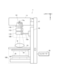
- FIG. 1 is a schematic diagram showing the overall image of the X-ray Talbot imaging apparatus 1.
- the X-ray Talbot imaging apparatus 1 includes an X-ray generator 11, the above-described source grating 12, a subject stage 13, the above-described first grating 14, the above-described second grating 15, It includes a line detector 16, a support 17, and a base 18.
- a moire image Mo of the subject H located at a predetermined position with respect to the subject stage 13 is captured by a method based on the principle of the fringe scanning method, and a moire image Mo is captured by Fourier imaging.
- a conversion method By analyzing using a conversion method, at least three types of images (two-dimensional images) can be reconstructed (referred to as reconstructed images). That is, an absorption image (same as a normal X-ray absorption image) that visualizes the average component of the moire fringe in the moire image Mo, a differential phase image that visualizes the phase information of the moire fringe, and a These are three types of small-angle scattering images. Note that it is also possible to generate more types of images by recombining these three types of reconstructed images.
- the fringe scanning method refers to scanning one of multiple gratings by 1/M of the slit period of the grating (M is a positive integer, M>2 for absorption images, M>3 for differential phase images and small-angle scattering images). ) This is a method in which reconstruction is performed using a moiré image Mo taken M times while moving in the slit period direction to obtain a high-definition reconstructed image.
- the Fourier transform method is a method in which a single moire image Mo is photographed using an X-ray Talbot imaging device in the presence of a subject, and in image processing, the moire image Mo is subjected to Fourier transform, etc., to create a differential phase image, etc. This is a method of reconstructing and generating images.
- the so-called vertical type is used, and the X-ray generator 11, the source grating 12, the subject stage 13, the first grating 14, the second grating 15, and the X-ray detector 16 are arranged in the gravity direction in this order. It is arranged in the z direction. That is, in this embodiment, the z direction is the irradiation direction of the X-rays from the X-ray generator 11.
- the X-ray generator 11 includes, as an X-ray source 11a, a Coolidge X-ray source, a rotating anode X-ray source, etc., which are widely used in medical settings, for example. It is also possible to use other X-ray sources.
- the X-ray generator 11 of this embodiment is configured to irradiate X-rays in a cone beam form from a focal point. That is, as shown in FIG.
- X-rays are irradiated with the X-ray irradiation axis Ca coinciding with the z direction as the central axis, and the X-rays are irradiated so as to spread further away from the X-ray generator 11 (that is, the X-ray irradiation range).
- a source grating 12 is provided below the X-ray generator 11. At this time, in order to prevent vibrations of the X-ray generator 11 caused by rotation of the anode of the X-ray source 11a from being transmitted to the source grating 12, in this embodiment, the source grating 12 is 11, but is attached to a fixing member 12a attached to a base portion 18 provided on the support column 17.
- a buffer member 17a is provided between the X-ray generator 11 and the support column 17.
- the fixing member 12a in addition to the source grating 12, the fixing member 12a includes a filter (also referred to as an additional filter) 112 for changing the quality of the X-rays transmitted through the source grating 12, and an irradiation filter.
- a filter also referred to as an additional filter
- a first cover unit 120 is arranged around the source grating 12 and the like to protect them.
- the controller 19 is a computer in which a CPU (Central Processing Unit), a ROM (Read Only Memory), a RAM (Random Access Memory), an input/output interface, etc. (not shown) are connected to a bus. It consists of Note that it is also possible to configure the controller 19 as a dedicated control device instead of a general-purpose computer as in this embodiment. Further, although not shown, the controller 19 is provided with appropriate means and devices such as an input means including an operation section, an output means, a storage means, and a communication means. The output means includes a display section (not shown) that displays information necessary for performing various operations of the X-ray Talbot imaging apparatus 1 and generated reconstructed images.
- a display section not shown
- the controller 19 is configured to perform general control over the X-ray Talbot imaging apparatus 1. That is, for example, the controller 19 is connected to the X-ray generator 11, and can set the tube voltage, tube current, irradiation time, etc. for the X-ray source 11a. Further, for example, it is also possible to configure the controller 19 to relay transmission and reception of signals and data between the X-ray detector 16 and the external image processing device 2, etc. That is, the controller 19 in this embodiment causes a series of shooting to be performed to obtain a plurality of moire images Mo (one moire image in the case of the Fourier transform method) necessary for generating a reconstructed image of the subject H. It functions as a control unit.
- moire images Mo one moire image in the case of the Fourier transform method
- control PC a general-purpose computer device
- the invention is not limited to this, and some of the functions of the control device 20 may be provided on a network so that each process can be executed by exchanging data through communication.
- the control device 20 includes a CPU 21 (Central Processing Unit), a RAM 22 (Random Access Memory), a storage section 23, an input section 24, a display section 25, a communication section 26, etc. .
- the CPU 21 reads various programs such as a system program and a processing program stored in the storage unit 23, expands them into the RAM 22, and executes various processes including an association process described later in accordance with the expanded programs. That is, the CPU 21 functions as a control unit for the entire X-ray imaging system.
- the CPU 21 stores a first image (parent image) of a first sample (parent sample) in a first storage unit (described later), and stores a second sample (child sample) cut out from the first sample in a second storage unit (described later). ) is stored in a third storage unit (to be described later), information on the cutout position of the second sample in the first sample and feature amounts at a position corresponding to the cutout position of the first image are stored, and the first image is stored. and the evaluation results of the second sample are associated using the information on the cutout position and the feature amount.
- the CPU 21 also functions as an acquisition unit that acquires proficiency information of a user who inputs information regarding selection of an area, which will be described later.
- the RAM 22 functions as a work area that temporarily stores various programs executable by the CPU 21 read from the storage unit 23, input or output data, parameters, etc. in various processes executed and controlled by the CPU 21.
- the storage unit 23 is composed of an HDD (Hard Disk Drive), a semiconductor nonvolatile memory, or the like.
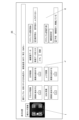
- the storage unit 23 stores the various programs described above, and also has a database shown in FIG. 3 for executing various processes such as those described later.
- the storage unit 23 functions as a first storage unit that stores a first image (parent image) obtained by photographing a first sample (parent sample) and in which predetermined quality information can be recognized.
- the storage unit 23 functions as a second storage unit that stores the evaluation results of the second samples (child samples) cut out from the first samples.
- the storage unit 23 functions as a third storage unit that stores information about the cutout position of the second sample in the first sample and the feature amount at the position corresponding to the cutout position of the first image.
- the parent sample information database 23a is a database that stores information regarding the subject H (parent sample).
- the parent sample information database 23a stores information such as sample ID, material, molding conditions, mold, etc.
- Material information includes the base material resin, the filler name and filler content in the case of composite materials, and the kneading conditions for the base material resin and filler, such as the screw shape of the kneader, back pressure, resin temperature, etc.
- the molding conditions include information about the temperature and pressure during molding, and molding time, such as the resin temperature in the screw, back pressure, injection speed, mold temperature, and cooling temperature.
- Mold information includes design drawings, gate position and gate diameter, runner shape, molded product shape (flat plate shape, dumbbell shape), and molded product size (information regarding width, height, and thickness).
- the parent image database 23b is a database that stores image data of the subject H.
- the parent image database 23b stores Talbot images (parent images) taken using the X-ray Talbot imaging device 1.
- the parent sample-child sample intermediate table 23c is a database that associates the parent sample information database 23a and the child sample information database 23d using sample IDs.
- the child sample information database 23d is a database that stores information regarding child samples cut out from the subject H.
- the child sample information database 23d stores sample IDs, extraction position information, feature amounts of selected positions (regions, ranges), selection know-how (child sample selection reasons, evaluation result predictions, know-how input person, etc.), etc.
- the feature amount of the selected position is a value extracted from the parent image and reflecting quality information, and is, for example, the average value or deviation of pixels in the selected area.
- the area of the region larger than a certain threshold value may be used as the feature amount of the region with a large amount of fibers, or the binarization processing and contour In combination with extraction, it also includes extracting the outline of an area above a certain threshold and counting the number of areas surrounded by the outline as a feature value as the number of areas where fibers aggregated.
- reason information information in the database regarding the child sample selection reason (reason for cutting out the second sample) is referred to as reason information.
- selection know-how (reason for selecting child samples, prediction of evaluation results, know-how input person, etc.) is used as information regarding region selection.
- the child image-child sample intermediate table 23e is a database that associates the child sample information database 23d with the child sample evaluation result database 23f.
- the child sample evaluation result database 23f is a database that stores measurement results of child samples.
- the child sample evaluation result database 23f stores child sample evaluation results and Talbot images (child images) taken using the X-ray Talbot imaging device 1.
- the child image is not limited to the Talbot image, but may be an optical image, an ultrasonic diagnostic image, a SEM (Scanning Electron Microscope) image, a ⁇ CT image, or the like.
- the material properties of the child sample may be evaluated by a tensile strength test, a Charpy impact test, a bending test, or a reliability test by repeated deformation, chemical application, or the like.
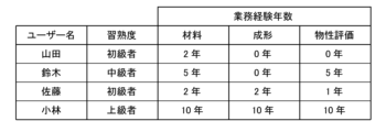
- the user information database 23g is a database that stores information regarding users who use the control device 20. For example, as shown in FIG. 4, the user information database 23g stores user names, proficiency levels (user proficiency information), years of work, and the like. Note that the user's proficiency information refers to information that corresponds to the user's work experience. For example, as shown in FIG. 4, by inputting the number of years of experience in material, molding, and physical property evaluation work, proficiency information may be used that considers a user with 5 years or more of material work as a veteran user.
- categories such as beginner, intermediate, advanced, beginner, and veteran may be explicitly prepared to classify each user.
- the evaluation results of the first image (parent image), the second sample (child sample), the information on the cutout position of the second sample in the first sample (parent sample), and the cutout position of the first image A feature amount at a position corresponding to (selected position) is associated with.
- the various databases described above may not only be stored in the storage unit 23 of the control device 20, but may also be provided on a network.
- the quality information relates to the quality of the subject H and includes fiber orientation, voids, cracks, foreign substances, density unevenness, fiber unevenness, and the like. Specifically, the density of the resin and fibers, the presence or absence of foreign substances such as metals inside the resin, the presence or absence of voids between the resin and the fibers, the presence or absence of voids inside the resin, and the presence or absence of voids formed by multiple fibers gathered together. The presence or absence of fiber bundles, the direction and degree of orientation of fibers, the density of fibers and fillers (e.g.
- the orientation information is the orientation and density of fibers included in the subject H.
- the orientation information includes voids and cracks, such as voids where the orientation is low and the amount of fiber is small. That is, the quality information includes orientation information.
- the input unit 24 includes a keyboard including cursor keys, numeric input keys, various function keys, etc., and a pointing device such as a mouse.
- the input unit 24 outputs a press signal of a key pressed on a keyboard or an operation signal from a mouse to the CPU 21 as an input signal.
- the CPU 21 can execute various processes based on operation signals from the input unit 24.
- the input unit 24 functions as an information input unit that inputs information regarding the selection of the area described above.
- the display unit 25 includes a monitor such as a CRT (Cathode Ray Tube) or an LCD (Liquid Crystal Display).
- the display unit 25 displays various screens according to instructions from display signals input from the CPU 21. Furthermore, when a touch panel is employed as the display section 25, the display section 25 also has the function of the input section 24.
- the communication unit 26 includes a communication interface and communicates with external devices on the network.
- the external devices on the network include the controller 19 of the X-ray Talbot imaging apparatus 1, and the controller 19 and the control device 20 are communicably connected via the communication unit 26.
- the control device 20 uses the various databases described above to perform various processes such as an association process, and the processes are executed based on a program stored in the storage unit 23.
- the association process executed in the control device 20 will be explained.
- the association process involves the evaluation results of the first image (parent image), the second sample (child sample), the information on the cutout position of the second sample in the first sample, and the position corresponding to the cutout position of the first image. This is the process of associating the feature amounts with.
- the CPU 21 registers information on the first sample (parent sample) input by the user via the input unit 24 in the parent sample information database 23a (step S1).
- the CPU 21 controls the controller 19, controls the X-ray Talbot imaging device 1, performs Talbot imaging of the first sample, and obtains a Talbot image (first image) of the parent sample (step S2).
- the CPU 21 registers the Talbot image of the parent sample in the parent image database 23b (step S3). Note that when the Talbot image is registered in the parent image database 23b, the parent sample information database 23a and the parent image database 23b are associated with each other.
- the CPU 21 analyzes the Talbot image (step S4). Specifically, as shown in a display area D to be described later, colors are divided according to the magnitude of the signal value of each pixel of the Talbot image. Note that, in order to facilitate judgment, all pixels below the threshold value are white. Further, it is preferable that the region to be grouped is set according to the shape of the sample to be cut out. for example. When measuring ash content (using the cutout area registration screen shown in FIG. 8, which will be described later), it is preferable to cut out the area into approximately 10 mm squares, so images corresponding to 10 mm squares are grouped and the characteristic amounts representative of the area are calculated. A mosaic process is performed to derive the information.
- the Talbot image size is an area of 50 mm x 50 mm, it will be displayed in a 5 x 5 area.
- the sample to be cut out has a dumbbell shape (dumbbell test piece) (when using the cutout area registration screen shown in FIG. 9, which will be described later)
- the representative width of the dumbbell test piece is 8 mm, Change the grouping area to 8mm square. This allows the user to determine which position in the Talbot image should be focused on, and also allows the user to explicitly indicate the position to be cut out.
- the CPU 21 causes the display unit 25 to display the Talbot image and the image analysis results on the image analysis result display screen shown in FIG. 6A (step S5). That is, the parent sample is evaluated using the Talbot image (first image).
- the user then refers to the image analysis result display screen shown in FIG. 6A and performs area selection, which will be described later.
- the image analysis result display screen shown in FIG. 6A will be described.
- Display area A is an area that displays sample IDs selected by the user.
- Display area B is an area where information about the sample corresponding to the sample ID displayed in display area A is displayed.
- Display area C is an area where Talbot images are displayed.
- Display area D is an area where image analysis results are displayed.
- FIG. 6B is a past evaluation result display screen. The user may refer to the past evaluation result display screen shown in FIG. 6B and select an area, which will be described later.
- the display area E is an area where the user selects an area (cutout area) from which a child sample is to be cut out from a parent sample.
- a specific method for registering a cutout area will be described below. For example, when the parent sample is a 50 mm flat plate and a 10 mm square child sample used for ash measurement is to be cut out using the cutout region registration screen shown in FIG. 8, guide lines are displayed at 10 mm intervals on the Talbot image.
- the cutout position information can be registered.
- the Talbot image may be displayed as is, or as shown in D in FIG. It's okay.
- the CPU 21 stores the ID of the child sample, the cutout shape, the upper left XY coordinates of the cutout position, and the cutout size in the DB (child sample information database 23d) as cutout position information.
- the parent sample is a flat plate and a dumbbell-shaped sample is cut out for a tensile test using the cutout area registration screen shown in FIG.
- the display area F is an area where information about the parent sample is displayed.
- the display area G is an area for displaying feature amounts extracted from the image portion of the cutout area selected in the display area E, the reason for selection by the user, and expected quality. In the example of FIG. 7, the average value and deviation of pixels are displayed as the feature amounts. Additionally, the user can input (or select) know-how such as the reason for selection (signal value, unevenness) and predictions (fiber amount, defibration). Note that in FIG. 7, information input by the input unit 24 is performed by selecting from options prepared in advance. By doing so, it becomes easier to analyze the correspondence between the options and the proficiency level of the person who inputs the know-how, which will be described later. For example, intermediate users tend to choose option A, while advanced users tend to choose option B.
- the display area H is an area where user information is displayed.
- the image of the cutout area is analyzed by the CPU 21, a feature amount is extracted, and the feature amount is displayed in the display area G. Further, when the selection of the cutout area and the like is completed, the CPU 21 registers information such as cutout position information, feature amount, selection know-how, know-how input person, etc. in the child sample information database 23d.
- the child sample information database 23d is associated with the parent sample information database 23a via the parent sample-child sample intermediate table 23c. Further, the user information database 23g is associated as information on the know-how input person.
- the CPU 21 uses information regarding area selection (selection know-how; child sample selection reason, evaluation results) based on the proficiency information included in the user information database 23g. Forecasts, know-how input persons, etc.) may be controlled whether to be associated with the parent sample information database 23a. For example, if the proficiency level is intermediate or higher as shown in FIG. 4, the information related to region selection is associated with the parent sample information database 23a, but if the proficiency level is beginner, it is not associated. It is also possible to control the weighting of associated information according to the level of proficiency. Note that this process will be described later as information association process regarding area selection.
- the cutting region selected by the user is cut out from the parent sample as a child sample.
- the CPU 21 controls the controller 19, controls the X-ray Talbot imaging device 1, and performs imaging of the child sample, etc. (step S7).
- position B is cut out, Talbot photography, photography using an optical microscope, and ash measurement are performed, and the fiber content can be evaluated from the weight change before and after the resin is evaporated or dissolved.
- the child samples shall be evaluated, such as the fiber length distribution of the remaining fibers or fillers. Furthermore, the evaluation method for child samples is not limited to these.
- the CPU 21 obtains image data and fiber amount data input by the user via the input unit 24 on the evaluation result registration screen shown in FIG. 10 (step S8).
- the display area I is a selection area where the user selects an area where a child sample is cut out from a parent sample.
- the display area J is a data (image data and fiber amount data) registration area.
- the parent image is a Talbot image, but the registered child image is not limited to a Talbot image, and may be an optical image, a SEM (Scanning Electron Microscope) image, a ⁇ CT image, or the like.
- the display area K is an area where the selection reason and prediction inputted on the area selection screen are displayed. Note that when the input is completed, the child sample evaluation result database 23f is registered. The child sample evaluation result database 23f is associated with the child sample information database 23d via the child image-child sample intermediate table 23e.
- the CPU 21 causes the display unit 25 to display the evaluation result display screen shown in FIG. 11 (step S9).
- position B is cut out and Talbot photography, photography using an optical microscope, and ash content measurement are performed, so position B is selected, and the Talbot image, optical image, fiber amount data, and area selection of the child sample are performed. The selection reasons and predictions entered will be displayed on the screen.
- the CPU 21 causes the display unit 25 to display the analysis result display screen shown in FIG. 12 (step S10).
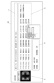
- a graph or the like can be displayed in which the horizontal axis is the feature quantity (statistical quantity) extracted from the Talbot image and the vertical axis is the evaluation result of the child sample.
- This makes it possible to compare the feature amounts and the evaluation results, making it easier to understand the meaning of the evaluation results.
- the pixel values of the parent image (Talbot image) and the corresponding tensile strength evaluation results can be confirmed. Furthermore, it is possible to visually judge which feature quantity is likely to have a correlation with tensile strength. Furthermore, as shown in the lower center diagram of FIG.
- the first component and second component of the principal component analysis can be selected and displayed as the feature amount of the Talbot image.
- this allows you to visually determine the presence or absence of correlations using feature values extracted using an inductive method (principal component analysis), and the meaning of evaluation results. becomes easier to understand.
- nine samples of dumbbell pieces that can form welds were prepared under different molding conditions and material conditions, and the results of a tensile strength test are shown.
- a Talbot image (an enlarged view of the weld area) of the parent sample of each sample is drawn, and the results of the tensile strength test are linked. This makes it possible to visually grasp the relationship between the tensile strength and the state of the weld portion, making it easier to judge what kind of feature quantity should be introduced.
- the CPU 21 obtains information about the person (user) who entered the area selection screen shown in FIG. 7 from the user information database 23g (step S21).
- the CPU 21 determines whether the input person's proficiency level is, for example, intermediate or higher (step S22).
- the criterion for judgment is whether the user is intermediate or above, but the criterion is not limited to this, and the criterion for judgment may be whether or not the user is advanced.
- step S22 if the user is intermediate or above (step S22; YES), the process advances to step S23. Further, in step S22, if the user is less than intermediate (step S22; NO), the information association process regarding region selection ends, and the information regarding region selection is not associated with the parent sample information database 23a.
- the CPU 21 associates information regarding region selection with the parent sample information database 23a (step S23). Then, the information association process regarding region selection ends. By doing this, it is possible to check the selection know-how of people with a high level of proficiency. Specifically, when another user opens the evaluation result display screen shown in FIG. 6B or FIG. Since the prediction will be displayed, even beginners can extract accurate samples by checking the know-how of the highly proficient inputter.
- the second sample is cut out in step S7, but the cutout position is manually input by the user.
- input position shifts, input errors, and input effort may occur. Therefore, in the second embodiment, the cutout position is automatically detected.
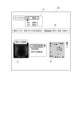
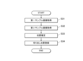
- the automatic extraction position detection process will be explained using FIG. 14.
- a parent sample (first sample) is subjected to Talbot imaging.
- the CPU 21 of the control device 20 acquires a parent sample image as shown in the upper row of FIG. 15 (step S21).
- a child sample (second sample) is physically cut out from the parent sample.
- the child sample is subjected to Talbot imaging using the X-ray Talbot imaging apparatus 1.
- the CPU 21 of the control device 20 acquires a child sample image as shown in the lower row of FIG. 15 (step S22).
- the CPU 21 performs pattern matching between the image of the parent sample and the image of the child sample, and estimates the position of the child sample in the parent sample (step S23).
- a general-purpose position search method such as opencv is used.
- the CPU 21 registers the estimated position information as a cutout position in the child sample information database 23d (step S24). In this way, instead of inputting the cutout position, the cutout position is estimated after the cutout and registered in the database, thereby preventing input position shifts, input errors, and input effort.
- a parent sample (first sample) is subjected to Talbot imaging.
- the CPU 21 of the control device 20 acquires a parent sample image as shown in the upper row of FIG. 18 (step S31).
- a child sample (second sample) is physically cut out from the parent sample.
- the child sample is subjected to Talbot imaging using the X-ray Talbot imaging apparatus 1.
- the CPU 21 of the control device 20 acquires a child sample image as shown in the lower row of FIG. 18 (step S32).
- the CPU 21 of the control device 20 extracts the image at the cutting position of the parent sample image (inside the upper frame in FIG. 18) and performs difference processing on the child sample image.
- the CPU 21 of the control device 20 generates a difference image as shown on the right side of FIG. 18 (step S33).
- the CPU 21 identifies locations affected by the cutout from the difference image (step S34). Specifically, in the example of the difference image on the right side of FIG. 18, the CPU 21 identifies that there are two cracks on the right side of the child sample.
- the signal values of the difference images may be subjected to arithmetic processing (such as addition as absolute values) to obtain a quantitative amount of change, which may be used as an index of damage due to processing.
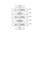
- a parent sample (first sample) is subjected to Talbot imaging.
- the CPU 21 of the control device 20 acquires a new parent sample image as shown on the right side of FIG. 20 (step S41).
- the CPU 21 calculates the degree of similarity between the new parent sample image and the parent sample image and child sample image (second sample image) taken in the past (step S42).
- the CPU 21 extracts parent sample images and child sample images with a high degree of similarity based on the calculated degree of similarity (step S43).
- the CPU 21 may extract only the one with the highest similarity, or extract a plurality (for example, three) of the similarities starting from the highest.
- the CPU 21 acquires information associated with the extracted parent sample image and child sample image from the storage unit 23 (step S44).
- the CPU 21 provides information on the cutout position, the reason for the cutout, and the evaluation performed on the child samples with respect to the parent samples with a high degree of similarity and the parent samples of child samples with a high degree of similarity.
- the results etc. are displayed on the display section 25 (step S45).
- the similarity can be calculated using a method using a histogram (using openCv's histogram similarity function), a method using template matching, or a method using AKAZE feature values and kNN (k-nearest neighbor algorithm). ). Furthermore, as image processing before similarity calculation, it is desirable to perform zero-filling processing on the background. Specifically, a process is performed in which contour extraction is performed and signals outside the sample contour are filled with zeros. In addition, small-angle scattering images and orientation images have signal value dependence depending on thickness, so when comparing subjects with different thicknesses, the levels of absolute values do not match and the degree of similarity decreases.
- an image obtained by dividing a small-angle scattering image by an absorption image (b) an eccentricity Ecc image, (c) an image obtained by dividing an Amp image by an Ave image, It is preferable to use .
- the Amp image refers to an image that represents the amplitude value (signal value amp) for each pixel
- the Ave image refers to an image that represents the average value (signal value ave) for each pixel (Japanese Patent Application Laid-Open No. 2021-089195 Public bulletin).
- the eccentricity Ecc image refers to an image showing the eccentricity ecc for each pixel.
- the image management system (X-ray Talbot imaging device 1, control device 20) is configured to control the area when the user selects an area from the first image of the first sample that can recognize predetermined quality information.
- the control unit (CPU 21) stores information regarding the selection in the storage unit (storage unit 23) in association with the first image based on the proficiency information of the user.
- the reasons and intentions for area selection can be accumulated as know-how.
- the first image is a Talbot image
- information such as fiber unevenness, defects, and voids You can tell from the image.
- control unit (CPU 21) associates the position information of the region in the first sample, the information regarding the selection of the region, and the first image and stores them in the storage unit (storage unit 23).
- storage unit 23 storage unit
- the control unit (CPU 21) also includes an information input unit (input unit 24) for inputting information regarding area selection, and an acquisition unit (CPU 21) for acquiring proficiency information of a user who inputs information regarding area selection. ) stores the know-how of a user with a high level of proficiency by associating information regarding region selection with the first image and storing it in the storage unit when the proficiency information acquired by the acquisition unit satisfies a predetermined criterion. Can be accumulated.
- the information input section allows the user to easily select an area by inputting information regarding area selection by selecting from options prepared in advance. Furthermore, it becomes easier to analyze the correspondence between the options and the proficiency level of the person inputting the know-how.
- control unit (CPU 21) can accurately grasp the cutting position of the child sample by specifying the positional information of the region in the first sample based on the second image of the region.
- the second image obtained by photographing the second sample cut out from the first sample is taken using the same photographing method as the first image, and the control unit (CPU 21) controls the image at the position selected from the first image and the second image.
- the control unit controls the image at the position selected from the first image and the second image.
- control unit acquires an image similar to the first sample and information associated with the acquired image from the storage unit (storage unit 23), and displays the acquired information on the display unit. , past knowledge can be utilized when determining the sample cutting position.
- the sample selection method includes, based on the user's proficiency information, information regarding the selection of the region when the user selects the region from the first image information of the first sample that can recognize the predetermined quality information.
- a step of storing the second sample in the storage unit in association with the first image information (step S6, step S23), and a step of cutting out a second sample from the selected region (step S7), or performing an image analysis of the selected region. step (step S6), the reasons and intentions for region selection can be accumulated as know-how when selecting regions from the parent sample and performing quality evaluation.
- the image management device (X-ray Talbot imaging device 1, control device 20) also provides information regarding the selection of the first region when the first region is selected from the first image information that can recognize the quality information in the first sample. Since the control unit (CPU 21) is configured to associate the image information with the first image information and store it in the storage unit (storage unit 23) based on the user's proficiency information, it is possible to select an area from the parent sample and perform quality evaluation. During implementation, the reasons and intentions for region selection can be accumulated as know-how.
- control unit acquires an image similar to the first sample from the storage unit, and causes the display unit (display unit 25) to display information regarding the selection of the area associated with the acquired image.
- display unit display unit 25
- the image display device (X-ray Talbot imaging device 1, control device 20) displays information regarding the region selection when the region is selected from the first image information in which the quality information of the first sample can be recognized.
- the control unit (CPU 21) is configured to store an image similar to the first sample from the storage unit in association with the first image information based on the proficiency information in the storage unit (storage unit 23).
- display unit 25 In order to display information regarding the selection of the region associated with the acquired image on the display unit (display unit 25), when selecting a region from the parent sample and performing quality evaluation, the reason and intention of the region selection are displayed. , can be confirmed as know-how.
- the program also controls the computer of the image management device (X-ray Talbot imaging device 1, control device 20) regarding selection of an area when selecting an area from the first image information that can recognize the quality information in the first sample.
- the image management device X-ray Talbot imaging device 1, control device 20
- CPU 21 control unit
- storage unit 23 storage unit
- first embodiment to the fourth embodiment may be combined as appropriate.
- the first image is a Talbot image, but the first image is not limited to this.
- an image taken using an optical microscope may be used, or an inspection device that can visually display cracks or the like may be used.
- the position (coordinates) of the cutout region may be based on a certain point of the first sample, or may be based on a certain point of the second sample.
- the CPU 21 also provides information about the cutout position, the reason for cutting out, and the cutout information regarding the parent samples with high similarity and the parent samples of child samples with high similarity, as shown in FIG.
- the evaluation results performed for the sample are displayed on the display unit 25, and the user cuts out the child sample based on that information, but the cutting position is automatically set on the cutting device without being displayed on the display unit 25. etc.
- the present disclosure can be used in image management systems, sample selection methods, image management devices, image display devices, and programs.
Landscapes
- Health & Medical Sciences (AREA)
- Analytical Chemistry (AREA)
- Physics & Mathematics (AREA)
- Life Sciences & Earth Sciences (AREA)
- Chemical & Material Sciences (AREA)
- Biochemistry (AREA)
- General Health & Medical Sciences (AREA)
- General Physics & Mathematics (AREA)
- Immunology (AREA)
- Pathology (AREA)
- Radiology & Medical Imaging (AREA)
- Nuclear Medicine, Radiotherapy & Molecular Imaging (AREA)
- Analysing Materials By The Use Of Radiation (AREA)
Abstract
親サンプルから領域を選択して品質評価を実施する際に、領域選択の理由や意図を、ノウハウとして蓄積できる画像管理システム、サンプル選択方法、画像管理装置、画像表示装置、及びプログラムを提供する。画像管理システム(X線タルボ撮影装置1、制御装置20)は、所定の品質情報を認識可能な第1サンプルの第1画像から、ユーザーが領域を選択した際の、領域の選択に関する情報を当該ユーザーの習熟度情報に基づいて、第1画像に関連付けして記憶部(記憶部23)に記憶させる制御部(CPU21)を備える。
Description
本発明は、画像管理システム、サンプル選択方法、画像管理装置、画像表示装置、及びプログラムに関する。
近年注目されている複合素材においては、材質そのものだけでなく、材料の微細な内部構造が部材の機械的な性質に大きな影響を及ぼす。例えばCFRP(Carbon Fiber Reinforced Plastics)であれば、炭素繊維の織り方や配向により、三次元的な構造を持っており、機械的な強度は、繊維配向性や繊維の密度に大きく影響される。
複合素材に限らず、樹脂開発初期段階では、材料や成形条件の異なる、ダンベル試験片や、平板などの、単純形状の試験サンプル(親サンプル)を大量に作成して、成形品内部状態の評価をするために、試験片から分析可能なサイズへの切り出しを行う事が一般的である。そして、切り出し後のサンプル(子サンプル)を使い、灰分測定後の繊維量・繊維長測定、μCTや光学顕微鏡、SEMにより、試験片表面や試験片内部の状態を確認する。また、材料特性の評価として、引張強度試験、シャルピー衝撃試験、曲げ試験、あるいは、繰り返し変形や薬品塗布等による信頼性試験を実施する。
これに関連して、親サンプルの画像(親画像)としてサンプル全体を俯瞰した撮影を行った後に、サンプルの特定箇所を拡大して撮影し子画像として保存して、親画像と子画像を関連付けて保存、画像表示する構成が開示されている(特許文献1)。
これに関連して、親サンプルの画像(親画像)としてサンプル全体を俯瞰した撮影を行った後に、サンプルの特定箇所を拡大して撮影し子画像として保存して、親画像と子画像を関連付けて保存、画像表示する構成が開示されている(特許文献1)。
しかしながら、親サンプルから、原因となる注目箇所(品質評価で不合格となる原因が生じると考えられる場所)を子サンプルとして的確に切り出すことができる評価者が限られていた。これは、熟練者の勘・コツ・経験によるところが大きいからである。
よって、勘・コツ・経験などを必要とせず、誰でも的確なサンプルを切り出すことができることが望まれる。
よって、勘・コツ・経験などを必要とせず、誰でも的確なサンプルを切り出すことができることが望まれる。
したがって、本発明の課題は、親サンプルから領域を選択して品質評価を実施する際に、領域の選択理由や意図を、ノウハウとして蓄積することを目的とする。
上記課題を解決するため、本発明の画像管理システムは、
所定の品質情報を認識可能な第1サンプルの第1画像から、ユーザーが領域を選択した際の、前記領域の選択に関する情報を当該ユーザーの習熟度情報に基づいて、前記第1画像に関連付けして記憶部に記憶させる制御部を備える。
所定の品質情報を認識可能な第1サンプルの第1画像から、ユーザーが領域を選択した際の、前記領域の選択に関する情報を当該ユーザーの習熟度情報に基づいて、前記第1画像に関連付けして記憶部に記憶させる制御部を備える。
また、本発明のサンプル選択方法は、
所定の品質情報を認識可能な第1サンプルの第1画像情報から、ユーザーが領域を選択した際の、前記領域の選択に関する情報を当該ユーザーの習熟度情報に基づいて、前記第
1画像情報に関連付けして記憶部に記憶させるステップと、
選択された前記領域から第2サンプルを切り出すステップ、もしくは、選択された前記領域の画像解析を行うステップと、
を含む。
所定の品質情報を認識可能な第1サンプルの第1画像情報から、ユーザーが領域を選択した際の、前記領域の選択に関する情報を当該ユーザーの習熟度情報に基づいて、前記第
1画像情報に関連付けして記憶部に記憶させるステップと、
選択された前記領域から第2サンプルを切り出すステップ、もしくは、選択された前記領域の画像解析を行うステップと、
を含む。
また、本発明の画像管理装置は、
第1サンプルにおける品質情報を認識可能な第1画像情報から領域を選択した際の、前記領域の選択に関する情報を、ユーザーの習熟度情報に基づいて、前記第1画像情報に関連付けして記憶部に記憶させる制御部を備える。
第1サンプルにおける品質情報を認識可能な第1画像情報から領域を選択した際の、前記領域の選択に関する情報を、ユーザーの習熟度情報に基づいて、前記第1画像情報に関連付けして記憶部に記憶させる制御部を備える。
また、本発明の画像表示装置は、
第1サンプルにおける品質情報を認識可能な第1画像情報から領域を選択した際の、前記領域の選択に関する情報を、ユーザーの習熟度情報に基づいて、前記第1画像情報に関連付けして記憶部に記憶させる制御部を備え、
前記制御部は、前記第1サンプルに類似した画像を、前記記憶部から取得し、取得した画像に関連付けられた前記領域の選択に関する情報を表示部に表示させる。
第1サンプルにおける品質情報を認識可能な第1画像情報から領域を選択した際の、前記領域の選択に関する情報を、ユーザーの習熟度情報に基づいて、前記第1画像情報に関連付けして記憶部に記憶させる制御部を備え、
前記制御部は、前記第1サンプルに類似した画像を、前記記憶部から取得し、取得した画像に関連付けられた前記領域の選択に関する情報を表示部に表示させる。
また、本発明のプログラムは、
画像管理装置のコンピューターを、
第1サンプルにおける品質情報を認識可能な第1画像情報から領域を選択した際の、前記領域の選択に関する情報を、ユーザーの習熟度情報に基づいて、前記第1画像情報に関連付けして記憶部に記憶させる制御部として機能させる。
画像管理装置のコンピューターを、
第1サンプルにおける品質情報を認識可能な第1画像情報から領域を選択した際の、前記領域の選択に関する情報を、ユーザーの習熟度情報に基づいて、前記第1画像情報に関連付けして記憶部に記憶させる制御部として機能させる。
本発明によれば、親サンプルから領域を選択して品質評価を実施する際に、領域選択の理由や意図を、ノウハウとして蓄積することができる。
以下、図面を参照して本発明の実施の形態について説明する。ただし、以下に述べる実施形態には、本発明を実施するために技術的に好ましい種々の限定が付されているが、本発明の技術的範囲を以下の実施形態および図示例に限定するものではない。
(第1実施形態)
本実施形態では、第1サンプル(親サンプル、被写体H)をX線タルボ撮影装置1によって撮影して得られ、所定の品質情報を認識可能な第1画像や、第1サンプルから切り出した第2サンプル(子サンプル)の評価結果や、第1サンプルにおける第2サンプルの切り出し位置の情報と、第1画像の切り出し位置に相当する位置における特徴量を記憶し、第1画像と、第2サンプルの評価結果と、切り出し位置の情報と、特徴量とを関連付けるX線撮影システムについて説明する。
関連付け処理を始めとする各種処理は、X線タルボ撮影装置1に接続された制御装置20によって行われる。
本実施形態では、第1サンプル(親サンプル、被写体H)をX線タルボ撮影装置1によって撮影して得られ、所定の品質情報を認識可能な第1画像や、第1サンプルから切り出した第2サンプル(子サンプル)の評価結果や、第1サンプルにおける第2サンプルの切り出し位置の情報と、第1画像の切り出し位置に相当する位置における特徴量を記憶し、第1画像と、第2サンプルの評価結果と、切り出し位置の情報と、特徴量とを関連付けるX線撮影システムについて説明する。
関連付け処理を始めとする各種処理は、X線タルボ撮影装置1に接続された制御装置20によって行われる。
[被写体について]
本実施形態における被写体Hは、複合素材(複合材料とも言う。)によって構成されており、例えば宇宙・航空機関係、自動車、船舶、つり竿の他、電気・電子・家電部品、パラボラアンテナ、浴槽、床材、屋根材等を始め、様々な製品等の構成部材として用いられるものである。
このような複合素材としては、例えば炭素繊維やガラス繊維を強化繊維として用いたCFRP(Carbon-Fiber-Reinforced Plastics:炭素繊維強化プラスチック)、CFRTP(Carbon Fiber Reinforced
Thermo Plastics:炭素繊維強化熱可塑性プラスチック)、GFRP(Glass-Fiber-Reinforced Plastics:ガラス繊維強化プラスチック)に代表されるFRP(Fiber-Reinforced Plastics:繊維強化プラスチック)や、セラミックス繊維を強化材とするCMC(Ceramic Matrix Composites:セラミック基複合材料)等が知られている。また、広義には、例えば合板のように複数種類の木材からなる複合素材が含まれるものとしてもよい。その他にも、例えば、MMC(Metal Matrix Composites:金属基複合材料)コンクリート、鉄筋コンクリート等のように、繊維を含まずに構成された複合材料も含まれるものとしてもよい。
なお、複合材料に用いられる樹脂は、例えば、汎用プラスチック、エンプラ、スーパーエンプラであるがこれらに限定されない。樹脂は、強度などの所定の特性を付加するためにマイクロサイズやナノサイズの構造を持つフィラーが添加される樹脂複合材料として用いられ、プラスチック成型加工品として使用されることが多い。フィラーには、有機材料、無機材料、磁性材料、金属材料がある。例えば、プラスチック成型加工品に強度や剛性を求められる場合には、樹脂としてPPS、POM、PA、PC、PPなど、フィラーとしてはアラミド繊維、タルク、セルロ―ス繊維など、の複合材料が用いられることがある。また、プラスチック成型加工品がプラマグである場合には、樹脂としてナイロン、フィラーとしてストロンチウムフェライト、サマリウムコバルトなど、の複合材料が用いられることがある。
[X線タルボ撮影装置について]
本実施形態においては、X線タルボ撮影装置1として、線源格子(マルチ格子やマルチスリット、G0格子等ともいう。)12を備えるタルボ・ロー干渉計を用いたものが採用されている。なお、線源格子12を備えず、第1格子(G1格子ともいう。)14と第2格子(G2格子ともいう。)15のみを備えるタルボ干渉計を用いたX線タルボ撮影装置を採用することもできる。
本実施形態においては、X線タルボ撮影装置1として、線源格子(マルチ格子やマルチスリット、G0格子等ともいう。)12を備えるタルボ・ロー干渉計を用いたものが採用されている。なお、線源格子12を備えず、第1格子(G1格子ともいう。)14と第2格子(G2格子ともいう。)15のみを備えるタルボ干渉計を用いたX線タルボ撮影装置を採用することもできる。
図1は、X線タルボ撮影装置1の全体像を表す概略図である。
本実施形態に係るX線タルボ撮影装置1は、X線発生装置11と、上記した線源格子12と、被写体台13と、上記した第1格子14と、上記した第2格子15と、X線検出器16と、支柱17と、基台部18と、を備えている。
本実施形態に係るX線タルボ撮影装置1は、X線発生装置11と、上記した線源格子12と、被写体台13と、上記した第1格子14と、上記した第2格子15と、X線検出器16と、支柱17と、基台部18と、を備えている。
このようなX線タルボ撮影装置1によれば、被写体台13に対して所定位置にある被写体Hのモアレ画像Moを、縞走査法の原理に基づく方法で撮影したり、モアレ画像Moを、フーリエ変換法を用いて解析したりすることで、少なくとも3種類の画像(二次元画像)を再構成することができる(再構成画像という)。すなわち、モアレ画像Moにおけるモアレ縞の平均成分を画像化した吸収画像(通常のX線の吸収画像と同じ)と、モアレ縞の位相情報を画像化した微分位相画像と、モアレ縞のVisibility(鮮明度)を画像化した小角散乱画像の3種類の画像である。なお、これらの3種類の再構成画像を再合成する等してさらに多くの種類の画像を生成することもできる。
なお、縞走査法とは、複数の格子のうちのひとつを格子のスリット周期の1/Mずつ(Mは正の整数、吸収画像はM>2、微分位相画像と小角散乱画像はM>3)スリット周期方向に移動させてM回撮影したモアレ画像Moを用いて再構成を行い、高精細の再構成画像を得る方法である。
また、フーリエ変換法とは、被写体が存在する状態で、X線タルボ撮影装置でモアレ画像Moを1枚撮影し、画像処理において、そのモアレ画像Moをフーリエ変換する等して微分位相画像等の画像を再構成して生成する方法である。
本実施形態に係るX線タルボ撮影装置1における他の部分の構成について説明する。本実施形態では、いわゆる縦型であり、X線発生装置11、線源格子12、被写体台13、第1格子14、第2格子15、X線検出器16が、この順序に重力方向であるz方向に配置されている。すなわち、本実施形態では、z方向が、X線発生装置11からのX線の照射方向ということになる。
X線発生装置11は、X線源11aとして、例えば医療現場で広く一般に用いられているクーリッジX線源や回転陽極X線源等を備えている。また、それ以外のX線源を用いることも可能である。本実施形態のX線発生装置11は、焦点からX線をコーンビーム状に照射するようになっている。つまり、図1に示すように、z方向と一致するX線照射軸Caを中心軸としてX線発生装置11から離れるほどX線が広がるように照射される(すなわち、X線照射範囲)。
そして、本実施形態では、X線発生装置11の下方に線源格子12が設けられている。その際、X線源11aの陽極の回転等により生じるX線発生装置11の振動が線源格子12に伝わらないようにするために、本実施形態では、線源格子12は、X線発生装置11には取り付けられず、支柱17に設けられた基台部18に取り付けられた固定部材12aに取り付けられている。
なお、本実施形態では、X線発生装置11の振動が支柱17等のX線タルボ撮影装置1の他の部分に伝播しないようにするために(あるいは伝播する振動をより小さくするために)、X線発生装置11と支柱17との間に緩衝部材17aが設けられている。
本実施形態では、上記の固定部材12aには、線源格子12のほか、線源格子12を透過したX線の線質を変えるためのろ過フィルター(付加フィルターともいう。)112や、照射されるX線の照射野を絞るための照射野絞り113、X線を照射する前にX線の代わりに可視光を被写体に照射して位置合わせを行うための照射野ランプ114等が取り付
けられている。
けられている。
なお、線源格子12とろ過フィルター112と照射野絞り113とは、必ずしもこの順番に設けられる必要はない。また、本実施形態では、線源格子12等の周囲には、それらを保護するための第1のカバーユニット120が配置されている。
また、コントローラー19(図1参照)は、本実施形態では、図示しないCPU(Central Processing Unit)やROM(Read Only Memory)、RAM(Random Access Memory)、入出力インターフェース等がバスに接続されたコンピューターで構成されている。なお、コントローラー19を、本実施形態のような汎用のコンピューターではなく、専用の制御装置として構成することも可能である。また、コントローラー19には、図示はしないが、操作部を含む入力手段や出力手段、記憶手段、通信手段等の適宜の手段や装置が設けられている。
出力手段には、X線タルボ撮影装置1の各種操作を行うために必要な情報や、生成された再構成画像を表示する表示部(図示省略)が含まれている。
出力手段には、X線タルボ撮影装置1の各種操作を行うために必要な情報や、生成された再構成画像を表示する表示部(図示省略)が含まれている。
コントローラー19は、X線タルボ撮影装置1に対する全般的な制御を行うようになっている。すなわち、例えば、コントローラー19は、X線発生装置11に接続されており、X線源11aに管電圧や管電流、照射時間等を設定することができるようになっている。また、例えば、コントローラー19が、X線検出器16と外部の画像処理装置2等との信号やデータの送受信を中継するように構成することも可能である。
つまり、本実施形態におけるコントローラー19は、被写体Hの再構成画像の生成に必要な複数のモアレ画像Mo(フーリエ変換法の場合は1枚のモアレ画像)を取得するための一連の撮影を行わせる制御部として機能している。
つまり、本実施形態におけるコントローラー19は、被写体Hの再構成画像の生成に必要な複数のモアレ画像Mo(フーリエ変換法の場合は1枚のモアレ画像)を取得するための一連の撮影を行わせる制御部として機能している。
[制御装置について]
本実施形態においては、各種処理を実行する制御装置20として、汎用のコンピューター装置(制御PC)が採用されている。ただし、これに限られるものではなく、制御装置20の機能の一部をネットワーク上に設け、通信によりデータを授受することで各処理を実行できるようにしてもよい。
制御装置20は、図2に示すように、CPU21(Central Processing Unit)や、RAM22(Random Access Memory)、記憶部23、入力部24、表示部25、通信部26等を備えて構成されている。
本実施形態においては、各種処理を実行する制御装置20として、汎用のコンピューター装置(制御PC)が採用されている。ただし、これに限られるものではなく、制御装置20の機能の一部をネットワーク上に設け、通信によりデータを授受することで各処理を実行できるようにしてもよい。
制御装置20は、図2に示すように、CPU21(Central Processing Unit)や、RAM22(Random Access Memory)、記憶部23、入力部24、表示部25、通信部26等を備えて構成されている。
CPU21は、記憶部23に記憶されているシステムプログラムや処理プログラム等の各種プログラムを読み出してRAM22に展開し、展開されたプログラムに従って、後述する関連付け処理を始めとする各種処理を実行する。すなわち、当該CPU21が、X線撮影システム全体における制御部として機能することになる。
CPU21は、後述する第1記憶部に、第1サンプル(親サンプル)の第1画像(親画像)を記憶させ、後述する第2記憶部に、第1サンプルから切り出した第2サンプル(子サンプル)の評価結果を記憶させ、後述する第3記憶部に、第1サンプルにおける第2サンプルの切り出し位置の情報と、第1画像の切り出し位置に相当する位置における特徴量を記憶させ、第1画像と第2サンプルの評価結果を、切り出し位置の情報と特徴量により関連付ける。
また、CPU21は、後述する領域の選択に関する情報を入力したユーザーの習熟度情報を取得する取得部としても機能する。
CPU21は、後述する第1記憶部に、第1サンプル(親サンプル)の第1画像(親画像)を記憶させ、後述する第2記憶部に、第1サンプルから切り出した第2サンプル(子サンプル)の評価結果を記憶させ、後述する第3記憶部に、第1サンプルにおける第2サンプルの切り出し位置の情報と、第1画像の切り出し位置に相当する位置における特徴量を記憶させ、第1画像と第2サンプルの評価結果を、切り出し位置の情報と特徴量により関連付ける。
また、CPU21は、後述する領域の選択に関する情報を入力したユーザーの習熟度情報を取得する取得部としても機能する。
RAM22は、CPU21により実行制御される各種処理において、記憶部23から読み出されたCPU21で実行可能な各種プログラム、入力若しくは出力データ、及びパラメーター等を一時的に記憶するワークエリアとして機能する。
記憶部23は、HDD(Hard Disk Drive)や半導体の不揮発性メモリー等により構成される。記憶部23には、上記した各種プログラムが記憶されている他、後述する処理などの各種処理を実行するために図3に示すデータベースを有している。
記憶部23は、第1サンプル(親サンプル)を撮影して得られ、所定の品質情報を認識可能な第1画像(親画像)を記憶する第1記憶部として機能する。
また、記憶部23は、第1サンプルから切り出した第2サンプル(子サンプル)の評価結果を記憶する第2記憶部として機能する。
また、記憶部23は、第1サンプルにおける第2サンプルの切り出し位置の情報と、第1画像の切り出し位置に相当する位置における特徴量を記憶する第3記憶部として機能する。
記憶部23は、第1サンプル(親サンプル)を撮影して得られ、所定の品質情報を認識可能な第1画像(親画像)を記憶する第1記憶部として機能する。
また、記憶部23は、第1サンプルから切り出した第2サンプル(子サンプル)の評価結果を記憶する第2記憶部として機能する。
また、記憶部23は、第1サンプルにおける第2サンプルの切り出し位置の情報と、第1画像の切り出し位置に相当する位置における特徴量を記憶する第3記憶部として機能する。
ここで、具体的に、記憶部23に記憶されているデータベース(DB)について、図3を用いて説明する。
親サンプル情報データベース23aは、被写体H(親サンプル)に関する情報を記憶するデータベースである。例えば、親サンプル情報データベース23aには、サンプルID、材料、成形条件、金型等の情報が記憶されている。材料の情報としては、母材となる樹脂、複合材料の場合はフィラー名称、フィラーの含有率、さらに、母材となる樹脂とフィラーの混錬条件として、混錬機のスクリュー形状、背圧、樹脂温度、などがある。成形条件としては、射出成型の場合は、スクリュー内の樹脂温度、背圧、射出速度、金型温度、冷却温度、などの、成型時の温度や圧力、成形時間に関する情報を示す。金型の情報としては、設計図面、ゲート位置やゲート径、ランナー形状、成型品の形状(平板形状、ダンベル形状)や、成型品のサイズ(幅、高さ、厚みに関する情報)などがある。
親画像データベース23bは、被写体Hの画像データを記憶するデータベースである。例えば、親画像データベース23bには、X線タルボ撮影装置1を用いて撮影されたタルボ画像(親画像)が記憶されている。
親サンプル-子サンプル中間テーブル23cは、サンプルIDを用いて、親サンプル情報データベース23aと子サンプル情報データベース23dを関連付けるデータベースである。
子サンプル情報データベース23dは、被写体Hから切り出した子サンプルに関する情報を記憶するデータベースである。例えば、子サンプル情報データベース23dには、サンプルID、切り出し位置情報、選択位置(領域、範囲)の特徴量、選択ノウハウ(子サンプル選択理由、評価結果予想、ノウハウ入力者等)等が記憶されている。ここで、選択位置の特徴量とは、親画像から抽出した、品質情報を反映した値であり、例えば、選択した領域の画素の平均値や偏差等である。他の例としては、親画像の選択した領域に対して、2値化処理を行った後にある閾値以上の領域の面積を、繊維量の多い領域の特徴量としたり、2値化処理と輪郭抽出と組み合わせることで、ある閾値以上の領域の輪郭を抽出し、その輪郭に囲まれた領域の個数をカウントした値を、繊維凝集した領域の個数として特徴量としたりすることなども含む。なお、子サンプル選択理由(第2サンプルを切り出した理由)に関するデータベースにおける情報を理由情報とする。また、選択ノウハウ(子サンプル選択理由、評価結果予想、ノウハウ入力者等)に関するデータベースにおける情報を領域の選択に関する情報とする。
子画像-子サンプル中間テーブル23eは、子サンプル情報データベース23dと子サンプル評価結果データベース23fを関連付けるデータベースである。
子サンプル評価結果データベース23fは、子サンプルの測定結果を記憶するデータベースである。例えば、子サンプル評価結果データベース23fには、子サンプル評価結果や、X線タルボ撮影装置1を用いて撮影されたタルボ画像(子画像)が記憶されている。なお、子画像はタルボ画像に限定されず、光学画像や超音波診断画像やSEM(Scanning Electron Microscope)画像、μCT画像等でもよい。
また、子サンプルに対する材料特性の評価として、引張強度試験、シャルピー衝撃試
験、曲げ試験、あるいは、繰り返し変形や薬品塗布等による信頼性試験などによる評価でもよい。
ユーザー情報データベース23gは、制御装置20を使用するユーザーに関する情報を記憶するデータベースである。例えば、図4に示すように、ユーザー情報データベース23gには、ユーザー名、習熟度(ユーザーの習熟度情報)、業務年数等が記憶されている。なお、ユーザーの習熟度情報とは、ユーザーの業務経験に応じた情報を指す。例えば、図4に示すように、材料、成形、物性評価の業務の経験年数を入力することで、材料業務5年以上をベテランユーザーとみなす習熟度情報としてもよい。また、明示的に、初心者、中級者、上級者、や、ビギナー、ベテランというカテゴリ分類を準備して、ユーザー毎に分類してもよい。
以上のように、第1画像(親画像)と、第2サンプル(子サンプル)の評価結果と、第1サンプル(親サンプル)における第2サンプルの切り出し位置の情報と、第1画像の切り出し位置に相当する位置(選択位置)における特徴量と、が関連付けられている。
なお、上記した各種データベースは、制御装置20の記憶部23に記憶されるだけでなく、ネットワーク上に設けられていてもよい。
ここで、品質情報について説明する。
品質情報とは、被写体Hの品質に係り、繊維配向、ボイド、クラック、異物、密度ムラ、繊維ムラなどを含む。具体的には、樹脂と繊維の密度の濃淡、樹脂内部に存在する金属等の異物の有無、樹脂と繊維の間に存在するボイドや樹脂内部のボイドの有無、繊維が複数本集まって形成される繊維束の有無、繊維の配向方向・配向度、繊維やフィラー(例:タルク)の密度の濃淡(繊維量のムラ)、ウエルド(発生位置、形状)、樹脂の流動方向(ゲート近傍、ゲート末端の流動方向など)、引張試験・ヒートサイクル試験・ケミカルアタック等により発生する微小クラック(クラック幅μmオーダーのもの等)、接着層の微小気泡(μmオーダーの気泡を検出)などが挙げられる。
配向情報とは、被写体Hに含まれる繊維の配向や密度である。例えば、配向が低く、繊維量が少ない箇所はボイドである等、配向情報には、ボイドやクラックも含む。
つまり、品質情報は、配向情報を含む。
入力部24は、カーソルキー、数字入力キー、及び各種機能キー等を備えたキーボードと、マウス等のポインティングデバイスを備えて構成される。入力部24は、キーボードで押下操作されたキーの押下信号やマウスによる操作信号を、入力信号としてCPU21に出力する。CPU21は、入力部24からの操作信号に基づいて、各種処理を実行することができる。
入力部24は、上述した領域の選択に関する情報を入力する情報入力部として機能する。
入力部24は、上述した領域の選択に関する情報を入力する情報入力部として機能する。
表示部25は、例えばCRT(Cathode Ray Tube)やLCD(Liquid Crystal Display)等のモニターを備えて構成されている。表示部25は、CPU21から入力される表示信号の指示に従って、各種画面を表示する。また、表示部25としてタッチパネルを採用する場合は、表示部25は、入力部24としての機能も併せ持つものとする。
通信部26は、通信インターフェースを備えており、ネットワーク上の外部装置と通信する。
ネットワーク上の外部装置には、X線タルボ撮影装置1のコントローラー19が含まれており、通信部26を介して、コントローラー19と制御装置20とが通信可能に接続されている。
ネットワーク上の外部装置には、X線タルボ撮影装置1のコントローラー19が含まれており、通信部26を介して、コントローラー19と制御装置20とが通信可能に接続されている。
制御装置20(CPU21)は、以上の各種データベースを用いて、関連付け処理など
の各種処理を行うが、その処理は、記憶部23に記憶されたプログラムに基づいて実行される。
の各種処理を行うが、その処理は、記憶部23に記憶されたプログラムに基づいて実行される。
[関連付け処理について]
制御装置20において実行される関連付け処理について説明する。関連付け処理とは、第1画像(親画像)と、第2サンプル(子サンプル)の評価結果と、第1サンプルにおける第2サンプルの切り出し位置の情報と、第1画像の切り出し位置に相当する位置における特徴量と、を関連付ける処理である。
制御装置20において実行される関連付け処理について説明する。関連付け処理とは、第1画像(親画像)と、第2サンプル(子サンプル)の評価結果と、第1サンプルにおける第2サンプルの切り出し位置の情報と、第1画像の切り出し位置に相当する位置における特徴量と、を関連付ける処理である。
まず、CPU21は、ユーザーにより入力部24を介して入力された第1サンプル(親サンプル)の情報を、親サンプル情報データベース23aに登録する(ステップS1)。
次に、CPU21は、コントローラー19を制御し、X線タルボ撮影装置1を制御し、第1サンプルのタルボ撮影を実施し、親サンプルのタルボ画像(第1画像)を取得する(ステップS2)。
次に、CPU21は、親サンプルのタルボ画像を親画像データベース23bに登録する(ステップS3)。なお、親画像データベース23bにタルボ画像が登録されると、親サンプル情報データベース23aと親画像データベース23bは、関連付けられる。
次に、CPU21は、タルボ画像を解析する(ステップS4)。
具体的には、後述する表示領域Dに示すように、タルボ画像の各画素の信号値の大きさに応じて、色分けをしている。なお、判断を容易にするために、閾値以下の画素は、全て白色としている。
また、切り出しを行うサンプル形状に応じてグルーピングする領域を設定されることが好ましい。例えば。灰分測定を行う場合(後述する図8に示す切り出し領域登録画面を用いる場合)は10mm角程度に切り出すのが好ましいので、10mm角に相当する画像をグルーピングして、その領域の代表する特徴量を導出するモザイク処理が行われる。例えば、タルボ画像サイズが50mm×50mmの領域の場合、5×5の領域で表示されることになる。
切り出すサンプルがダンベル形状(ダンベル試験片)の場合(後述する図9に示す切り出し領域登録画面を用いる場合)は、ダンベル試験片を代表する幅(例えば、短辺の幅)が8mmであれば、グルーピングする領域を8mm角に変更する。
これにより、ユーザーは、タルボ画像のどの位置に注目すべきか判断でき、また、切り出す位置を明示的に示すことが可能になる。
次に、CPU21は、表示部25にタルボ画像と画像解析結果を、図6Aに示す画像解析結果表示画面に表示させる(ステップS5)。つまり、親サンプルは、タルボ画像(第1画像)を用いて、評価される。そして、ユーザーは、図6Aに示す画像解析結果表示画面を参照し、後述する領域選択を行う。
ここで、図6Aに示す画像解析結果表示画面について説明する。
表示領域Aは、ユーザーにより選択されるサンプルIDを表示する領域である。
表示領域Bは、表示領域Aにおいて表示されたサンプルIDに対応するサンプルの情報を表示する領域である。
表示領域Cは、タルボ画像を表示する領域である。
表示領域Dは、画像解析結果を表示する領域である。
なお、図6Bは、過去の評価結果表示画面である。ユーザーは、図6Bに示す過去の評価結果表示画面を参照し、後述する領域選択を行ってもよい。
ここで、図6Aに示す画像解析結果表示画面について説明する。
表示領域Aは、ユーザーにより選択されるサンプルIDを表示する領域である。
表示領域Bは、表示領域Aにおいて表示されたサンプルIDに対応するサンプルの情報を表示する領域である。
表示領域Cは、タルボ画像を表示する領域である。
表示領域Dは、画像解析結果を表示する領域である。
なお、図6Bは、過去の評価結果表示画面である。ユーザーは、図6Bに示す過去の評価結果表示画面を参照し、後述する領域選択を行ってもよい。
次に、CPU21は、図7に示す領域選択画面において、ユーザーにより入力部24を
介して入力された、第2サンプルの切り出し位置選択結果や、選択理由及び第2サンプル測定予想結果を取得する(ステップS6)。
ここで、図7に示す領域選択画面について説明する。
表示領域Eは、ユーザーにより親サンプルから子サンプルを切り出す領域(切り出し領域)を選択する領域である。以下に、具体的な切り出し領域を登録する方法を記載する。
例えば、図8に示す切り出し領域登録画面を用いて、親サンプルが50mmの平板で、灰分測定に用いる10mm角の子サンプルを切り出す場合、タルボ画像上に10mm間隔でガイド線が表示されており、区分けした領域の1つを選択し、登録ボタンを押下することで、切り出し位置情報を登録することができる。なお、図8に示す切り出し領域登録画面において、タルボ画像をそのまま表示してもよいし、図6AのDのように、切り出すサンプルの大きさに応じた区画毎の特徴量に応じた表示を行っても良い。そして、CPU21は、子サンプルのIDとともに、切り出し形状、切り出し位置の左上のXY座標、切り出しサイズを切り出し位置情報としてDB(子サンプル情報データベース23d)に保存する。
また、例えば、図9に示す切り出し領域登録画面を用いて、親サンプルが平板で、引張試験用にダンベル形状のサンプルを切り出す場合(なお、ダンベル試験片の短辺の幅は10mmとする)、タルボ画像上に10mm間隔でガイド線が表示され、切り出す予定のダンベル形状を画像上でカーソル移動させ、登録ボタンを押下することで、ユーザーは切り出し位置を指定することができる。そして、CPU21は、子サンプルのIDとともに、切り出し形状としてダンベル形状、切り出し位置の左上のXY座標、切り出し方向の角度情報、を切り出し位置情報としてDB(子サンプル情報データベース23d)に保存する。
なお、切り出し領域としたが、後述するステップS7において切り出さず、選択した領域をさらに画像処理してもよい。
表示領域Fは、親サンプルの情報を表示する領域である。
表示領域Gは、表示領域Eにて選択されている切り出し領域の画像部分から抽出した特徴量と、ユーザーによる選択理由や予想される品質を表示する領域である。図7の例では、特徴量として、画素の平均値と偏差を表示している。また、ユーザーは、選択理由(信号値、ムラ)や予想(繊維量、解繊)などのノウハウを、入力(もしくは選択)することができる。
なお、図7では、入力部24による情報入力は、予め用意された選択肢からの選択によって行われる。このようにすることで、選択肢と後述するノウハウ入力者の習熟度の対応関係を分析しやすくなる。例えば、中級者では、選択肢Aを選ぶ傾向にあるが、上級者では、選択肢Bを選ぶ傾向にあることが挙げられる。
表示領域Hは、ユーザー情報を表示する領域である。
なお、表示領域Eにて子サンプルの切り出し領域が選択されると、その切り出し領域がCPU21により画像解析され、特徴量が抽出され、当該特徴量が表示領域Gに表示される。
また、切り出し領域の選択などが完了すると、CPU21は、切り出し位置情報や特徴量、選択ノウハウ、ノウハウ入力者等の情報を、子サンプル情報データベース23dに登録する。そして、子サンプル情報データベース23dは、親サンプル-子サンプル中間テーブル23cを介して、親サンプル情報データベース23aに関連付けられる。また、ノウハウ入力者の情報として、ユーザー情報データベース23gが関連付けられる。
また、CPU21は、子サンプル情報データベース23dと親サンプル情報データベース23aを関連付ける際に、ユーザー情報データベース23gに含まれる習熟度情報に基づき、領域の選択に関する情報(選択ノウハウ;子サンプル選択理由、評価結果予想、ノウハウ入力者等)を、親サンプル情報データベース23aに関連付けるかどうか制御してもよい。例えば、図4に示すような習熟度が、中級者以上の場合は、領域の選択に関する情報を親サンプル情報データベース23aに関連付けるが、初級者の場合は、関連付けないという制御である。また、習熟度に応じて、関連付けられた情報の重み付けをする制御
も可能である。なお、本処理については、領域の選択に関する情報関連付け処理として後述する。
次に、子サンプルの切り出し装置を用い、ユーザーにより選択された切り出し領域を、子サンプルとして親サンプルから切り出す。CPU21は、コントローラー19を制御し、X線タルボ撮影装置1を制御し、子サンプルの撮影等を行う(ステップS7)。なお、本実施形態では、位置Bを切り出し、タルボ撮影、光学顕微鏡を用いた撮影、灰分測定が実施され、樹脂を蒸発、または、溶解させた前後の重量変化から繊維量含有量の評価や、残った繊維ないしフィラーの繊維長の分布の評価、などの子サンプルの評価がされるものとする。また、子サンプルの評価方法は、これらに限られない。
次に、CPU21は、図10に示す評価結果登録画面において、ユーザーにより入力部24を介して入力された、画像データや繊維量データを取得する(ステップS8)。
表示領域Iは、ユーザーにより親サンプルから子サンプルを切り出した領域を選択する選択領域である。
表示領域Jは、データ(画像データや繊維量データ)登録領域である。本実施形態では、親画像はタルボ画像であるが、登録される子画像はタルボ画像に限定されず、光学画像やSEM(Scanning Electron Microscope)画像、μCT画像等でもよい。
表示領域Kは、領域選択画面にて入力された選択理由や予想が表示される領域である。
なお、入力が完了すると、子サンプル評価結果データベース23fが登録される。そして、子サンプル評価結果データベース23fは、子画像-子サンプル中間テーブル23eを介して、子サンプル情報データベース23dに関連付けられる。
次に、CPU21は、図11に示す評価結果表示画面を、表示部25に表示させる(ステップS9)。本実施形態では、位置Bを切り出し、タルボ撮影、光学顕微鏡を用いた撮影、灰分測定が実施されているため、位置Bが選択され、子サンプルのタルボ画像・光学画像・繊維量データ、領域選択画面にて入力された選択理由や予想が表示されることとなる。
次に、CPU21は、図12に示す分析結果表示画面を、表示部25に表示させる(ステップS10)。例えば、タルボ画像から抽出した特徴量(統計量)を横軸とし、縦軸を子サンプルの評価結果としたグラフなどを表示できる。
これにより、特徴量と評価結果を比較することができ、評価結果の意味を理解しやすくなる。例えば、親画像(タルボ画像)の画素の値と、対応する引張強度の評価結果を確認できる。また、どの特徴量が、引張強度と相関がありそうか、について視覚的に判断する事ができる。
また、図12下段中央図のように、タルボ画像の特徴量として、主成分分析の第1成分と第2成分を選択して表示する事ができる。縦軸と横軸として、第1主成分と第2主成分を設定し、各サンプルに紐づく引張強度の結果をバブルチャートとして表現した例である。これにより、平均値や偏差などの簡易的な特徴量に加えて、帰納的な手法(主成分分析)で抽出された特徴量による、相関関係の有無を視覚的にとらえられ、評価結果の意味を理解しやすくなる。
また、図12下段左下図のように、ウエルドができるダンベル片について、成形条件や材料条件が異なる9個のサンプルを作成して、引張強度試験を行った結果を示している。それぞれのサンプルの親サンプルのタルボ画像(ウエルド部分を拡大したもの)を描画するとともに、引張強度試験の結果が紐づけられている。これにより、引張強度とウエルド部の状態の関係を視覚的に把握することができ、どんな特徴量を導入すべきか、判断しやすくなる。
[領域の選択に関する情報関連付け処理について]
上述したように、図7に示す領域選択画面の入力が完了すると、子サンプル情報データベース23dは、親サンプル-子サンプル中間テーブル23cを介して、親サンプル情報データベース23aに関連付けられるが、図4に示すような習熟度の情報(習熟度情報)によって、領域の選択に関する情報を親サンプル情報データベース23aに関連付けるかどうか制御すること(領域の選択に関する情報関連付け処理)が可能である。図13を用いて、領域の選択に関する情報関連付け処理を説明する。
上述したように、図7に示す領域選択画面の入力が完了すると、子サンプル情報データベース23dは、親サンプル-子サンプル中間テーブル23cを介して、親サンプル情報データベース23aに関連付けられるが、図4に示すような習熟度の情報(習熟度情報)によって、領域の選択に関する情報を親サンプル情報データベース23aに関連付けるかどうか制御すること(領域の選択に関する情報関連付け処理)が可能である。図13を用いて、領域の選択に関する情報関連付け処理を説明する。
まず、CPU21は、図7に示す領域選択画面の入力者(ユーザー)の情報を、ユーザー情報データベース23gから取得する(ステップS21)。
次に、CPU21は、入力者の習熟度が、例えば、中級者以上であるか判断する(ステップS22)。ここでは、中級者以上かどうかを判断基準としているが、これに限定されず、上級者かどうか等を判断の基準としてもよい。ステップS22において、中級者以上の場合(ステップS22;YES)、ステップS23に進む。また、ステップS22において、中級者未満の場合(ステップS22;NO)、領域の選択に関する情報関連付け処理は終了し、領域の選択に関する情報は、親サンプル情報データベース23aに関連付けられない。
次に、CPU21は、領域の選択に関する情報を親サンプル情報データベース23aに関連付ける(ステップS23)。そして、領域の選択に関する情報関連付け処理は終了する。
このようにすることで、習熟度が高い人の選択ノウハウを確認できる。具体的には、別のユーザーが、過去の試験結果を確認する際に、図6Bや図11に示す評価結果表示画面を開くと、習熟度が高い入力者の子サンプル選択理由や子サンプル評価予測が表示されることとなるため、初級者でも習熟度が高い入力者のノウハウを確認することで、的確なサンプルを切り出すことができる。
(第2実施形態)
上記第1実施形態では、ステップS7において第2サンプルの切り出しを行っているが、切り出し位置の入力は、ユーザーにより手動で行われている。そのため、入力位置のずれや、入力ミス、入力の手間、が発生する。
そのため、第2実施形態では、切り出し位置の自動検出を行う。図14を用いて、切り出し位置自動検出処理を説明する。
上記第1実施形態では、ステップS7において第2サンプルの切り出しを行っているが、切り出し位置の入力は、ユーザーにより手動で行われている。そのため、入力位置のずれや、入力ミス、入力の手間、が発生する。
そのため、第2実施形態では、切り出し位置の自動検出を行う。図14を用いて、切り出し位置自動検出処理を説明する。
まず、X線タルボ撮影装置1を用いて、親サンプル(第1サンプル)をタルボ撮影する。制御装置20のCPU21は、図15上段のような親サンプル画像を取得する(ステップS21)。
次に、親サンプルから子サンプル(第2サンプル)を物理的に切り出す。
次に、X線タルボ撮影装置1を用いて、子サンプルをタルボ撮影する。制御装置20のCPU21は、図15下段のような子サンプル画像を取得する(ステップS22)。
次に、CPU21は、図16のように、親サンプルの画像と子サンプルの画像をパターンマッチングし、親サンプルにおける子サンプルの位置を推定する(ステップS23)。例えば、opencvなどの汎用的な位置探索手法を利用する。
次に、CPU21は、推定した位置情報を切り出し位置として子サンプル情報データベース23dに登録する(ステップS24)。
これにより、切り出し位置を入力するのではなく、切り出した後に、切り出し位置を推定し、データベースに登録することで、入力位置のずれや、入力ミス、入力の手間の発生を防ぐことができる。
(第3実施形態)
上記第1実施形態や第2実施形態では、子サンプルを物理的に切り出すが、切り出した
(サンプルを加工した)ことによるダメージが分からない。
そのため、第3実施形態では、子サンプル切り出し前の親画像と、子サンプルを物理的に切り出した後に撮影した子画像とを、比較することにより、切り出しによる影響を把握する。図20を用いて、切り出し影響特定処理を説明する。
上記第1実施形態や第2実施形態では、子サンプルを物理的に切り出すが、切り出した
(サンプルを加工した)ことによるダメージが分からない。
そのため、第3実施形態では、子サンプル切り出し前の親画像と、子サンプルを物理的に切り出した後に撮影した子画像とを、比較することにより、切り出しによる影響を把握する。図20を用いて、切り出し影響特定処理を説明する。
まず、X線タルボ撮影装置1を用いて、親サンプル(第1サンプル)をタルボ撮影する。制御装置20のCPU21は、図18上段のような親サンプル画像を取得する(ステップS31)。
次に、親サンプルから子サンプル(第2サンプル)を物理的に切り出す。
次に、X線タルボ撮影装置1を用いて、子サンプルをタルボ撮影する。制御装置20のCPU21は、図18下段のような子サンプル画像を取得する(ステップS32)。
次に、制御装置20のCPU21は、親サンプルの画像の切り出し位置の画像を抜き出して(図18上段枠内)、子サンプルの画像の差分処理を行う。制御装置20のCPU21は、図18右側のような差分画像を生成する(ステップS33)。
次に、CPU21は、差分画像から切り出しによる影響箇所を特定する(ステップS34)。具体的には、CPU21は、図18右側の差分画像の例では、子サンプルの右側に2か所の亀裂が入っていることを特定する。
なお、差分画像の信号値を演算処理(絶対値として加算など)して、定量的な変化量を求め、加工によるダメージの指標としてもよい。
(第4実施形態)
切り出し位置の決定に際し、切り出しの経験が十分にある人では、切り出し位置の決定に迷いが生じることは少ないが、経験が浅い人では、迷いが生じることがある。
そのため、第4実施形態では、サンプルの切り出し位置を決める際に、過去の知見を活かせるようにする。つまり、過去に撮影した親サンプルの画像や、親画像から切り出した子画像の中から、対象となるサンプルの親画像に類似する事例を探しだし、切り出した位置の情報や切り出した理由、子サンプルに対して実施した評価結果、などの情報を提示する。図19を用いて、類似サンプル情報表示処理について説明する。
切り出し位置の決定に際し、切り出しの経験が十分にある人では、切り出し位置の決定に迷いが生じることは少ないが、経験が浅い人では、迷いが生じることがある。
そのため、第4実施形態では、サンプルの切り出し位置を決める際に、過去の知見を活かせるようにする。つまり、過去に撮影した親サンプルの画像や、親画像から切り出した子画像の中から、対象となるサンプルの親画像に類似する事例を探しだし、切り出した位置の情報や切り出した理由、子サンプルに対して実施した評価結果、などの情報を提示する。図19を用いて、類似サンプル情報表示処理について説明する。
まず、X線タルボ撮影装置1を用いて、親サンプル(第1サンプル)をタルボ撮影する。制御装置20のCPU21は、図20右側のような新規の親サンプル画像を取得する(ステップS41)。
次に、CPU21は、新規の親サンプル画像と、過去に撮影した親サンプル画像や子サンプル画像(第2サンプルの画像)との類似度を算出する(ステップS42)。
次に、CPU21は、算出した類似度に基づき、類似度が高い親サンプル画像や子サンプル画像を抽出する(ステップS43)。
具体的には、CPU21は、類似度が最も高いもののみ抽出したり、最も高いものから順に複数(例えば、3つ)抽出したりすることが挙げられる。
次に、CPU21は、抽出した親サンプル画像や子サンプル画像に関連付けられた情報を、記憶部23から取得する(ステップS44)。
次に、CPU21は、図21に示すような、類似度の高い親サンプルや、類似度の高い子サンプルの親サンプルに関して、切り出した位置の情報や切り出した理由、子サンプルに対して実施した評価結果等、を表示部25に表示させる(ステップS45)。
なお、類似度の算出方法は、具体的には、ヒストグラムを利用する方法(openCvのヒストグラム類似度関数を利用)や、テンプレートマッチングを利用する方法や、AKAZE特徴量とkNN(k-nearest neighbor algorithm)を組み合わせた方法などが挙げられる。
また、類似度算出前の画像処理として、背景を0埋め処理するのが望ましい。具体的には、輪郭抽出を行い、サンプルの輪郭外の信号を0埋めする処理を実施する。
また、小角散乱画像や配向画像は、厚みによる信号値依存性があるため、厚みが異なる被写体を比較する場合、絶対値のレベルが合わず、類似度が低下してしまう。被写体の厚みが異なる影響を低減して比較したい場合は、(あ)小角散乱画像を吸収画像で除算した画像、(い)偏心度Ecc画像、(う)Amp画像をAve画像で除算した画像、を使う事が望ましい。
なお、Amp画像とは、画素ごとの振幅値(信号値amp)を表す画像を指し、Ave画像とは、画素ごとの平均値(信号値ave)を示す画像を指す(特開2021-089195号公報)。また、偏心度Ecc画像とは、画素ごとの偏心度eccを示す画像を指す。偏心度eccは、配向画像から得られた信号値amp、aveを用いてσ1=ave+amp(小角信号値の最大値に相当)と、σ2=ave-amp(小角信号値の最小値に相当)を算出した場合、下記式を用いて算出される。
(効果)
以上説明したように、画像管理システム(X線タルボ撮影装置1、制御装置20)は、所定の品質情報を認識可能な第1サンプルの第1画像から、ユーザーが領域を選択した際の、領域の選択に関する情報を当該ユーザーの習熟度情報に基づいて、第1画像に関連付けして記憶部(記憶部23)に記憶させる制御部(CPU21)を備えることで、親サンプルから領域を選択して品質評価を実施する際に、領域選択の理由や意図を、ノウハウとして蓄積することができる。
以上説明したように、画像管理システム(X線タルボ撮影装置1、制御装置20)は、所定の品質情報を認識可能な第1サンプルの第1画像から、ユーザーが領域を選択した際の、領域の選択に関する情報を当該ユーザーの習熟度情報に基づいて、第1画像に関連付けして記憶部(記憶部23)に記憶させる制御部(CPU21)を備えることで、親サンプルから領域を選択して品質評価を実施する際に、領域選択の理由や意図を、ノウハウとして蓄積することができる。
また、第1画像は、タルボ画像であるため、繊維のムラ、欠陥、ボイドなどの情報を取得することができ、切り出したサンプルの品質である配向の異方性や、ボイドの多い少ない、を画像から判断できる。
また、制御部(CPU21)は、第1サンプルにおける領域の位置情報と、領域の選択に関する情報と、第1画像とを関連付けして記憶部(記憶部23)に記憶させることで、親サンプルから領域を選択して品質評価を実施する際に、領域選択の理由や意図を、ノウハウとして蓄積することができる。
また、領域の選択に関する情報を入力する情報入力部(入力部24)と、領域の選択に関する情報を入力したユーザーの習熟度情報を取得する取得部(CPU21)と、を備え、制御部(CPU21)は、取得部により取得した習熟度情報が所定の基準を満たす場合に、領域の選択に関する情報を第1の画像に関連付けして記憶部に記憶させることで、習熟度が高いユーザーのノウハウを蓄積できる。
また、情報入力部は、予め用意された選択肢からの選択によって、領域の選択に関する情報を入力することで、ユーザーは選択しやすくなる。また、選択肢とノウハウ入力者の習熟度の対応関係を分析しやすくなる。
また、制御部(CPU21)は、領域を撮像した第2画像に基づいて、第1サンプルにおける領域の位置情報を特定することで、子サンプルの切り出し位置を正確に把握できる。
また、第1サンプルから切り出した第2サンプルを撮影した第2画像は、第1画像と同じ撮影手法であり、制御部(CPU21)は、第1画像から選択された位置における画像
と第2画像を比較すること第2サンプルの切り出し前後の変化を特定するため、サンプルを加工したことによるダメージを確認できる。
と第2画像を比較すること第2サンプルの切り出し前後の変化を特定するため、サンプルを加工したことによるダメージを確認できる。
また、制御部(CPU21)は、第1サンプルに類似した画像と、取得した画像に関連付けられた情報と、を記憶部(記憶部23)から取得し、取得した情報を表示部に表示させるため、サンプルの切り出し位置を決める際に、過去の知見を活かすことができる。
また、サンプル選択方法は、所定の品質情報を認識可能な第1サンプルの第1画像情報から、ユーザーが領域を選択した際の、領域の選択に関する情報を当該ユーザーの習熟度情報に基づいて、第1画像情報に関連付けして記憶部に記憶させるステップ(ステップS6、ステップS23)と、選択された領域から第2サンプルを切り出すステップ(ステップS7)、もしくは、選択された領域の画像解析を行うステップ(ステップS6)と、を含むため、親サンプルから領域を選択して品質評価を実施する際に、領域選択の理由や意図を、ノウハウとして蓄積することができる。
また、画像管理装置(X線タルボ撮影装置1、制御装置20)は、第1サンプルにおける品質情報を認識可能な第1画像情報から第1領域を選択した際の、第1領域の選択に関する情報を、ユーザーの習熟度情報に基づいて、第1の画像情報に関連付けして記憶部(記憶部23)に記憶させる制御部(CPU21)を備えるため、親サンプルから領域を選択して品質評価を実施する際に、領域選択の理由や意図を、ノウハウとして蓄積することができる。
また、制御部(CPU21)は、第1サンプルに類似した画像を、記憶部から取得し、取得した画像に関連付けられた領域の選択に関する情報を表示部(表示部25)に表示させるため、親サンプルから領域を選択して品質評価を実施する際に、領域選択の理由や意図を、ノウハウとして確認することができる。
また、画像表示装置(X線タルボ撮影装置1、制御装置20)は、第1サンプルにおける品質情報を認識可能な第1画像情報から領域を選択した際の、領域の選択に関する情報を、ユーザーの習熟度情報に基づいて、第1画像情報に関連付けして記憶部(記憶部23)に記憶させる制御部(CPU21)を備え、制御部は、第1サンプルに類似した画像を、記憶部から取得し、取得した画像に関連付けられた領域の選択に関する情報を表示部(表示部25)に表示させるため、親サンプルから領域を選択して品質評価を実施する際に、領域選択の理由や意図を、ノウハウとして確認することができる。
また、プログラムは、画像管理装置(X線タルボ撮影装置1、制御装置20)のコンピューターを、第1サンプルにおける品質情報を認識可能な第1画像情報から領域を選択した際の、領域の選択に関する情報を、ユーザーの習熟度情報に基づいて、第1画像情報に関連付けして記憶部(記憶部23)に記憶させる制御部(CPU21)として機能させるため、親サンプルから領域を選択して品質評価を実施する際に、領域選択の理由や意図を、ノウハウとして蓄積することができる。
以上、本発明の実施形態について説明したが、上述した本実施形態における記述は、本発明に係る好適な一例であり、これに限定されるものではない。
例えば、第1実施形態から第4実施形態を適宜組み合わせてもよい。
また、上記の説明では、第1画像はタルボ画像としたが、これに限定されない。例えば、光学顕微鏡を用いて撮影した画像でもよいし、クラックなどを視覚的に表示可能な検査装置でもよい。
また、切り出し領域の位置(座標)は、第1サンプルのある点を基準としてもよいし、第2サンプルのある点を基準としてもよい。
また、第4実施形態では、CPU21は、図19に示すような、類似度の高い親サンプルや、類似度の高い子サンプルの親サンプルに関して、切り出した位置の情報や切り出した理由、子サンプルに対して実施した評価結果等、を表示部25に表示させ、ユーザーがその情報を基に子サンプルを切り出すこととなるが、表示部25に表示させず、自動で切り出し装置に切り出し位置を設定するなどしてもよい。
また、上記の説明では、本発明に係るプログラムのコンピューター読み取り可能な媒体としてハードディスクや半導体の不揮発性メモリー等を使用した例を開示したが、この例に限定されない。その他のコンピューター読み取り可能な媒体として、CD-ROM等の可搬型記録媒体を適用することが可能である。
その他、各装置の細部構成及び細部動作に関しても、発明の趣旨を逸脱することのない範囲で適宜変更可能である。
本開示は、画像管理システム、サンプル選択方法、画像管理装置、画像表示装置、及びプログラムに利用できる。
1 X線タルボ撮影装置
11 X線発生装置
19 コントローラー
2 画像処理装置
20 制御装置
21 CPU(制御部)
22 RAM
23 記憶部
23a 親サンプル情報データベース
23b 親画像データベース
23c 親サンプル-子サンプル中間テーブル
23d 子サンプル情報データベース
23e 子画像-子サンプル中間テーブル
23f 子サンプル評価結果データベース
23g ユーザー情報データベース
24 入力部(情報入力部)
25 表示部
26 通信部
H 被写体(検査対象物)
11 X線発生装置
19 コントローラー
2 画像処理装置
20 制御装置
21 CPU(制御部)
22 RAM
23 記憶部
23a 親サンプル情報データベース
23b 親画像データベース
23c 親サンプル-子サンプル中間テーブル
23d 子サンプル情報データベース
23e 子画像-子サンプル中間テーブル
23f 子サンプル評価結果データベース
23g ユーザー情報データベース
24 入力部(情報入力部)
25 表示部
26 通信部
H 被写体(検査対象物)
Claims (17)
- 所定の品質情報を認識可能な第1サンプルの第1画像から、ユーザーが領域を選択した際の、前記領域の選択に関する情報を当該ユーザーの習熟度情報に基づいて、前記第1画像に関連付けして記憶部に記憶させる制御部を備える画像管理システム。
- 前記品質情報は、繊維の配向情報を含む請求項1に記載の画像管理システム。
- 前記第1画像は、タルボ画像である請求項1記載に記載の画像管理システム。
- 前記制御部は、前記第1サンプルにおける前記領域の位置情報と、前記領域の選択に関する情報と、前記第1画像とを関連付けして前記記憶部に記憶させる請求項1記載の画像管理システム。
- 前記領域の選択に関する情報を入力する情報入力部と、
前記領域の選択に関する情報を入力したユーザーの習熟度情報を取得する取得部と、を備え、
前記制御部は、前記取得部により取得した習熟度情報が所定の基準を満たす場合に、前記領域の選択に関する情報を前記第1画像に関連付けして前記記憶部に記憶させる請求項1記載の画像管理システム。 - 前記情報入力部は、予め用意された選択肢からの選択によって、前記領域の選択に関する情報を入力する請求項5記載の画像管理システム。
- 前記制御部は、前記領域を撮影した第2画像に基づいて、前記第1サンプルにおける前記領域の位置情報を特定する請求項1記載の画像管理システム。
- 前記第1サンプルから切り出した第2サンプルを撮影した第2画像は、前記第1画像と同じ撮影手法であり、
前記制御部は、前記第1画像から選択された位置における画像と前記第2画像を比較すること前記第2サンプルの切り出し前後の変化を特定する請求項1に記載の画像管理システム。 - 前記制御部は、前記第1サンプルに類似した画像と、取得した画像に関連付けられた情報と、を前記記憶部から取得し、取得した情報を表示部に表示させる請求項1に記載の画像管理システム。
- 所定の品質情報を認識可能な第1サンプルの第1画像情報から、ユーザーが領域を選択した際の、前記領域の選択に関する情報を当該ユーザーの習熟度情報に基づいて、前記第1画像情報に関連付けして記憶部に記憶させるステップと、
選択された前記領域から第2サンプルを切り出すステップ、もしくは、選択された前記領域の画像解析を行うステップと、
を含む、サンプル選択方法。 - 前記第1画像情報は、繊維の配向情報に関わる請求項10に記載のサンプル選択方法。
- 第1サンプルにおける品質情報を認識可能な第1画像情報から領域を選択した際の、前記領域の選択に関する情報を、ユーザーの習熟度情報に基づいて、前記第1画像情報に関連付けして記憶部に記憶させる制御部を備える画像管理装置。
- 前記制御部は、前記第1サンプルに類似した画像を、前記記憶部から取得し、取得した画像に関連付けられた前記領域の選択に関する情報を表示部に表示させる請求項12に記載の画像管理装置。
- 前記第1画像情報は、繊維の配向情報に関わる請求項12に記載の画像管理装置。
- 第1サンプルにおける品質情報を認識可能な第1画像情報から領域を選択した際の、前記領域の選択に関する情報を、ユーザーの習熟度情報に基づいて、前記第1画像情報に関連付けして記憶部に記憶させる制御部を備え、
前記制御部は、前記第1サンプルに類似した画像を、前記記憶部から取得し、取得した画像に関連付けられた前記領域の選択に関する情報を表示部に表示させる画像表示装置。 - 前記第1画像情報は、繊維の配向情報に関わる請求項15に記載の画像表示装置。
- 画像管理装置のコンピューターを、
第1サンプルにおける品質情報を認識可能な第1画像情報から領域を選択した際の、前記領域の選択に関する情報を、ユーザーの習熟度情報に基づいて、前記第1画像情報に関連付けして記憶部に記憶させる制御部として機能させるプログラム。
Applications Claiming Priority (2)
| Application Number | Priority Date | Filing Date | Title |
|---|---|---|---|
| JP2022121146 | 2022-07-29 | ||
| JP2022-121146 | 2022-07-29 |
Publications (1)
| Publication Number | Publication Date |
|---|---|
| WO2024024796A1 true WO2024024796A1 (ja) | 2024-02-01 |
Family
ID=89706361
Family Applications (1)
| Application Number | Title | Priority Date | Filing Date |
|---|---|---|---|
| PCT/JP2023/027237 WO2024024796A1 (ja) | 2022-07-29 | 2023-07-25 | 画像管理システム、サンプル選択方法、画像管理装置、画像表示装置、及びプログラム |
Country Status (1)
| Country | Link |
|---|---|
| WO (1) | WO2024024796A1 (ja) |
Citations (6)
| Publication number | Priority date | Publication date | Assignee | Title |
|---|---|---|---|---|
| US4158766A (en) * | 1977-03-25 | 1979-06-19 | Saab-Scania Aktiebolag | Inspection of elongated workpieces such as random length boards |
| JP2014192743A (ja) * | 2013-03-27 | 2014-10-06 | Olympus Corp | 撮像装置、構図アシスト装置、構図アシスト方法、及び構図アシストプログラム |
| JP2018159691A (ja) * | 2017-03-24 | 2018-10-11 | 三菱ケミカル株式会社 | 繊維強化複合材料の繊維蛇行状態の評価方法 |
| JP2021120639A (ja) * | 2020-01-30 | 2021-08-19 | 株式会社日立製作所 | アラート出力タイミング制御装置、アラート出力タイミング制御方法、アラート出力タイミング制御プログラム |
| JP2022052102A (ja) * | 2020-09-23 | 2022-04-04 | コニカミノルタ株式会社 | 情報処理装置、学習装置、情報処理システム、情報処理方法、プログラム、および、記録媒体 |
| JP2023088704A (ja) * | 2021-12-15 | 2023-06-27 | コニカミノルタ株式会社 | 放射線撮影装置、画像生成方法、放射線撮影システム、及びプログラム |
-
2023
- 2023-07-25 WO PCT/JP2023/027237 patent/WO2024024796A1/ja unknown
Patent Citations (6)
| Publication number | Priority date | Publication date | Assignee | Title |
|---|---|---|---|---|
| US4158766A (en) * | 1977-03-25 | 1979-06-19 | Saab-Scania Aktiebolag | Inspection of elongated workpieces such as random length boards |
| JP2014192743A (ja) * | 2013-03-27 | 2014-10-06 | Olympus Corp | 撮像装置、構図アシスト装置、構図アシスト方法、及び構図アシストプログラム |
| JP2018159691A (ja) * | 2017-03-24 | 2018-10-11 | 三菱ケミカル株式会社 | 繊維強化複合材料の繊維蛇行状態の評価方法 |
| JP2021120639A (ja) * | 2020-01-30 | 2021-08-19 | 株式会社日立製作所 | アラート出力タイミング制御装置、アラート出力タイミング制御方法、アラート出力タイミング制御プログラム |
| JP2022052102A (ja) * | 2020-09-23 | 2022-04-04 | コニカミノルタ株式会社 | 情報処理装置、学習装置、情報処理システム、情報処理方法、プログラム、および、記録媒体 |
| JP2023088704A (ja) * | 2021-12-15 | 2023-06-27 | コニカミノルタ株式会社 | 放射線撮影装置、画像生成方法、放射線撮影システム、及びプログラム |
Similar Documents
| Publication | Publication Date | Title |
|---|---|---|
| JP7067221B2 (ja) | X線撮影システム | |
| Glud et al. | Automated counting of off-axis tunnelling cracks using digital image processing | |
| Salaberger et al. | Evaluation of computed tomography data from fibre reinforced polymers to determine fibre length distribution | |
| JP5164777B2 (ja) | 液体物品の検査方法及びその設備 | |
| Smith et al. | Progress in 3D characterisation and modelling of monolithic carbon-fibre composites | |
| Devivier et al. | Impact damage detection in composite plates using deflectometry and the Virtual Fields Method | |
| Jespersen et al. | Uncovering the fatigue damage initiation and progression in uni-directional non-crimp fabric reinforced polyester composite | |
| Holmes et al. | Digital image and volume correlation for deformation and damage characterisation of fibre-reinforced composites: A review | |
| JP7484610B2 (ja) | 情報処理装置、学習装置、情報処理システム、情報処理方法、プログラム、および、記録媒体 | |
| CN104272094A (zh) | 缺陷判定装置、放射线摄像系统及缺陷判定方法 | |
| JP2018091765A (ja) | 画像解析装置、方法およびプログラム | |
| Swery et al. | Automated tool to determine geometric measurements of woven textiles using digital image analysis techniques | |
| US20210170635A1 (en) | Molding support apparatus and molding support method | |
| Denos et al. | Progressive failure analysis in platelet based composites using CT-measured local microstructure | |
| EP4180197A1 (en) | Program for inspecting molded article region, method for inspecting molded article region, and device for inspecting molded article region | |
| WO2024024796A1 (ja) | 画像管理システム、サンプル選択方法、画像管理装置、画像表示装置、及びプログラム | |
| Lobanov et al. | Mathematical data processing according to digital image correlation method for polymer composites | |
| WO2024024797A1 (ja) | 画像管理システム、画像管理装置、画像管理方法及び画像管理プログラム | |
| Sanabria et al. | In-situ quantification of microscopic contributions of individual cells to macroscopic wood deformation with synchrotron computed tomography | |
| CN111351810B (zh) | 一种含多尺度缺陷金属断裂失效行为的分析方法 | |
| Sisodia et al. | The effects of voids in quasi-static indentation of resin-infused reinforced polymers | |
| Cilley et al. | Methods of fiber and void measurement in graphite/epoxy composites | |
| Cosmi et al. | Threshold identification for micro‐tomographic damage characterisation in a short‐fibre‐reinforced polymer | |
| Hittawe et al. | A machine vision based approach for timber knots detection | |
| JP2022093509A (ja) | X線撮影システム |
Legal Events
| Date | Code | Title | Description |
|---|---|---|---|
| 121 | Ep: the epo has been informed by wipo that ep was designated in this application |
Ref document number: 23846526 Country of ref document: EP Kind code of ref document: A1 |