WO2024024745A1 - 測定装置、受光器、及び投光器 - Google Patents
測定装置、受光器、及び投光器 Download PDFInfo
- Publication number
- WO2024024745A1 WO2024024745A1 PCT/JP2023/027061 JP2023027061W WO2024024745A1 WO 2024024745 A1 WO2024024745 A1 WO 2024024745A1 JP 2023027061 W JP2023027061 W JP 2023027061W WO 2024024745 A1 WO2024024745 A1 WO 2024024745A1
- Authority
- WO
- WIPO (PCT)
- Prior art keywords
- light
- viewing range
- reflected light
- entrance surface
- diffraction grating
- Prior art date
- Legal status (The legal status is an assumption and is not a legal conclusion. Google has not performed a legal analysis and makes no representation as to the accuracy of the status listed.)
- Ceased
Links
Images






Classifications
-
- G—PHYSICS
- G01—MEASURING; TESTING
- G01C—MEASURING DISTANCES, LEVELS OR BEARINGS; SURVEYING; NAVIGATION; GYROSCOPIC INSTRUMENTS; PHOTOGRAMMETRY OR VIDEOGRAMMETRY
- G01C3/00—Measuring distances in line of sight; Optical rangefinders
- G01C3/02—Details
- G01C3/06—Use of electric means to obtain final indication
-
- G—PHYSICS
- G01—MEASURING; TESTING
- G01S—RADIO DIRECTION-FINDING; RADIO NAVIGATION; DETERMINING DISTANCE OR VELOCITY BY USE OF RADIO WAVES; LOCATING OR PRESENCE-DETECTING BY USE OF THE REFLECTION OR RERADIATION OF RADIO WAVES; ANALOGOUS ARRANGEMENTS USING OTHER WAVES
- G01S7/00—Details of systems according to groups G01S13/00, G01S15/00, G01S17/00
- G01S7/48—Details of systems according to groups G01S13/00, G01S15/00, G01S17/00 of systems according to group G01S17/00
- G01S7/481—Constructional features, e.g. arrangements of optical elements
-
- G—PHYSICS
- G01—MEASURING; TESTING
- G01S—RADIO DIRECTION-FINDING; RADIO NAVIGATION; DETERMINING DISTANCE OR VELOCITY BY USE OF RADIO WAVES; LOCATING OR PRESENCE-DETECTING BY USE OF THE REFLECTION OR RERADIATION OF RADIO WAVES; ANALOGOUS ARRANGEMENTS USING OTHER WAVES
- G01S17/00—Systems using the reflection or reradiation of electromagnetic waves other than radio waves, e.g. lidar systems
- G01S17/88—Lidar systems specially adapted for specific applications
- G01S17/89—Lidar systems specially adapted for specific applications for mapping or imaging
- G01S17/894—Three-dimensional [3D] imaging with simultaneous measurement of time-of-flight at a two-dimensional [2D] array of receiver pixels, e.g. time-of-flight cameras or flash lidar
Definitions
- the present disclosure relates to a measuring device, a light receiver, and a light projector, and particularly relates to a technique for expanding the viewing range of a measuring device.
- LiDAR Development/research on light detection and ranging is progressing.
- LiDAR includes a light projector that projects (irradiates) a laser beam onto a measurement target, and a light receiver that receives reflected light that is reflected by the laser light and returns to the measurement target.
- LiDAR provides information about a measurement target by measuring the distance to the measurement target based on the difference between the timing at which a light projector emits a laser beam and the timing at which a light receiver receives reflected light.
- Patent Document 1 describes a LiDAR system configured for implementation in a vehicle.
- a LiDAR system includes multiple light emitters (such as Vertical Cavity Surface Emitting Laser (VCSEL) devices) that generate multiple optical beams.
- VCSEL Vertical Cavity Surface Emitting Laser
- a LiDAR system has a first lens that focuses a plurality of optical beams into a focused optical beam having a beam waist, and a second lens that projects the focused optical beam onto a target area.
- VCSEL Vertical Cavity Surface Emitting Laser
- Flash LiDAR uses a method in which a projector diffuses and irradiates laser light over a viewing range. Flash LiDAR does not include mechanical components such as motors or MEMS (Micro Electro Mechanical Systems), so it is attracting attention as a promising candidate for LiDAR in fields where durability is required, such as when used for automotive purposes. There is.
- the field of view (FOV: viewing angle, beam profile, light distribution size) of the flash LiDAR receiver and emitter is determined by the size (area) of the light receiver and emitter and the optical system (receiving optical system, light emitter). It is determined by the focal length of the optical system). For this reason, when applying flash LiDAR to an individual system such as a ranging sensor for a vehicle, it is necessary to configure the system so that the field of view satisfies the specifications required by the system to which it is applied.
- the present disclosure has been made in view of this background, and aims to provide a measuring device, a light projector, and a light receiver that can flexibly respond to specifications required by the system to which the system is applied.
- One aspect of the present disclosure is a measuring device that includes a light projector and a light receiver that receives reflected light generated by the light projector projecting light toward a viewing range, and the light receiver includes a light receiving section and a light receiving section. , a transmission type diffraction grating, wherein the first reflected light from the first viewing range enters the light receiving section as a first order diffracted light, and the first reflected light from the first viewing range enters the light receiving section, The second reflected light from the second visual field lined up is incident on the light receiving section as second order diffracted light.
- a measuring device including a light projector and a light receiver that receives reflected light generated by the projector projecting light toward a viewing range
- the projector includes a light emitting section. and a transmission type diffraction grating, the diffraction grating emits first-order diffracted light generated when light from the light emitting section passes through the diffraction grating toward a first viewing range.
- the second-order diffracted light generated when the light passes through the diffraction grating is emitted toward a second viewing range that is aligned with the first viewing range.
- a measurement device including a light projector and a light receiver that receives reflected light generated by the light projector projecting light toward a viewing range, and the light receiver receives light. and a transmissive optical element, the optical element having a first incident surface on which the first reflected light from the first viewing range is incident, and a transmissive optical element that is continuous with the first incident surface.
- the first incident surface is inclined with respect to the first incident surface with a boundary line with the first incident surface as a fold line.
- a measuring device including a light projector and a light receiver that receives reflected light generated by the projector projecting light toward a viewing range
- the projector includes a light emitting section. and a transmissive optical element, wherein the optical element includes an incident surface on which light from the light emitting section is incident, and a first surface that emits the light incident on the incident surface toward a first viewing range. and a second exit surface that outputs the light incident on the entrance surface toward a second viewing range, the entrance surface, the first exit surface, and the second exit surface. All of the output surfaces are flat surfaces, and the second output surface is inclined with respect to the first output surface with a boundary line with the second output surface as a fold.
- a measuring device a light projector, and a light receiver that can flexibly respond to specifications required by the system to which the system is applied.
- FIG. 1 is a diagram showing a schematic configuration of a measuring device.
- FIG. 2A is a diagram illustrating the relationship between the light receiving section, the light receiving optical system, and the viewing range.
- FIG. 2B is a diagram illustrating the relationship between the light emitting unit, the projection optical system, and the viewing range.
- FIG. 3 is a diagram illustrating the relationship between the light receiver and the viewing range when a diffraction grating is used in the light receiving optical system according to the first embodiment.
- FIG. 4A is a diagram illustrating one aspect of the configuration of a measuring device that distinguishes from which viewing range the reflected light comes.
- FIG. 4B is a diagram showing one aspect of the arrangement of diffraction gratings.
- FIG. 1 is a diagram showing a schematic configuration of a measuring device.
- FIG. 2A is a diagram illustrating the relationship between the light receiving section, the light receiving optical system, and the viewing range.
- FIG. 2B is a diagram illustrating the relationship between the
- FIG. 5A is a diagram showing the relationship between the visual field range and the received light image in the configuration shown in FIG. 4A.
- FIG. 5B is a diagram showing the relationship between the viewing range and the received light image when the direction in which the slits of the diffraction grating are arranged is not rotated around the optical axis.
- FIG. 6 is a diagram illustrating parameters that determine the characteristics of the diffraction grating.
- FIG. 7 is a diagram illustrating the relationship between the projector and the viewing range when a diffraction grating is used in the projecting optical system according to the second embodiment.
- FIG. 8 is a diagram illustrating the relationship between the light receiver and the viewing range according to the third embodiment.
- FIG. 9A is an external perspective view of an optical element applied to the light receiver of FIG. 8.
- FIG. 9B is a side view of an optical element applied to the light receiver of FIG. 8.
- FIG. 10A is a diagram illustrating one aspect of the configuration of a measuring device that distinguishes from which viewing range the reflected light comes from.
- FIG. 10B is an external perspective view of the optical element used in the configuration of FIG. 10A.
- FIG. 11 is a diagram illustrating the relationship between the projector and the viewing range according to the fourth embodiment.
- FIG. 12A is an external perspective view of an optical element applied to the projector of FIG. 11.
- FIG. 12B is a side view of an optical element applied to the projector of FIG. 11.
- FIG. 1 shows a schematic configuration (block diagram) of a measuring device 100 as an embodiment of the present disclosure.
- the measuring device 100 includes a light projector that projects (irradiates) light (irradiation light, light beam (laser light)) onto a measurement target, and a reflected light (return light) that reflects the projected light onto the measurement target and returns to the measurement target. ), and functions as a flash LiDAR (Flash Light Detection and Ranging).
- the measuring device 100 measures the difference between the timing at which the projector emits the projected light and the timing at which the receiver receives the reflected light (the flight time of the laser beam, hereinafter referred to as "TOF" (Time Of Flight)). to obtain information about the measurement target.
- TOF Time Of Flight
- the measuring device 100 is installed, for example, in a vehicle in which AD (Autonomous Driving) or ADAS (Advanced Driver Assistance System) is installed.
- AD Autonomous Driving
- ADAS Advanced Driver Assistance System
- the measuring device 100 assists in detecting people, other vehicles, and objects while the vehicle is running, as well as ensuring the safety of the vehicle driver and those around the vehicle.
- the illustrated measurement device 100 includes a light emitting section 11, a light projection control device 112, a current source 113, a light projection optical system 14, a light receiving optical system 15, a light receiving section 16, a TOF measurement device 117, and a calculation device. 150, and a communication I/F 160 (I/F:Interface).
- the light emitting section 11, the light projection control device 112, the current source 113, and the light projection optical system 14 constitute a light projector
- the light receiving optical system 15 and the light receiving section 16 constitute a light receiver.
- the light emitting unit 11 constituting the floodlight includes one or more light emitting elements or one or more light emitting element arrays (for example, light emitting elements arranged in a linear (one-dimensional) or planar (two-dimensional) manner. ).
- the light emitting element include a laser diode, a surface emitting type laser emitting element (e.g., VCSEL (Vertical Cavity Surface Emitting Laser), hereinafter referred to as a "surface emitting element”), and a plurality of surface emitting elements that are one-dimensional.
- VCSEL Vertical Cavity Surface Emitting Laser
- it is a surface emitting element array (for example, a VCSEL array) arranged two-dimensionally on a substrate (semiconductor substrate, ceramic substrate, etc.).
- the light projection control device 112 generates a control signal for a current source 113 that supplies a drive current for a light emitting element constituting the light emitting unit 11 and inputs the control signal to the current source 113, so that the control signal is supplied from the current source 113 to the light emitting element. Controls the current (drive current).
- the light projection control device 112 inputs to the TOF measuring device 117 a signal indicating the timing at which the light emitting element emits light (the timing at which the projected light is emitted from the light emitting element; hereinafter referred to as "light projection timing").
- the light projection control device 112 controls the light emitting elements to periodically and repeatedly turn on and off a current flowing through each of the light emitting elements, for example, thereby causing the light emitting elements to periodically and repeatedly emit light.
- the current source 113 supplies a current to the light emitting element according to a control signal input from the light projection control device 112.
- the current source 113 supplies, for example, a periodic square wave current to the light emitting elements to turn on and off the current flowing through each of the light emitting elements.
- the light projection optical system 14 adjusts the light distribution of the projected light by, for example, applying an optical effect (refraction, scattering, diffraction, etc.) to the projected light emitted from the light emitting unit 11.
- the light projection optical system 14 is configured using, for example, various lenses such as a collimating lens, optical components such as a reflecting mirror (mirror), and the like.
- the light-receiving optical system 15 collects reflected light (return light), which is the light projected by the light projector and reflected by the measurement object 50 or the like, onto the light-receiving section 16 .
- the light receiving optical system 15 is configured using optical components such as various lenses such as a condenser lens, various filters such as a wavelength filter, and a reflecting mirror.
- the light receiving section 16 includes one or more light receiving elements (a plurality of light receiving elements), or one or more light receiving element arrays (for example, light receiving elements are arranged in a linear (one-dimensional) or planar (two-dimensional) manner. It is composed of The above light receiving element is, for example, a photodiode, a SPAD (Single Photon Avalanche Diode), a balanced photodetector, or the like.
- the light receiving unit 16 photoelectrically converts the reflected light incident from the light receiving optical system 15 to generate a current (hereinafter referred to as "light receiving current") according to the intensity of the reflected light.
- the light receiving section 16 performs TOF measurement of a signal indicating the timing at which each light receiving element constituting the light receiving section 16 receives reflected light (hereinafter referred to as "light receiving timing") and the light receiving current generated by each light receiving element. input to device 117;
- the TOF measurement device 117 determines the TOF based on the signal indicating the light emission timing inputted from the light emission control device 112 and the signal indicating the light reception timing inputted from the light receiving section 16.
- the TOF measurement device 117 is configured using, for example, a time measurement IC (Integrated Circuit) equipped with a TDC (Time to Digital Converter) circuit.
- the TOF measuring device 117 inputs the determined TOF and the light receiving current input from the light receiving section 16 to the arithmetic device 150.
- the arithmetic unit 150 is configured using a processor (CPU (Central Processing Unit), MPU (Micro Processing Unit), ASIC (Application Specific Integrated Circuit), FPGA (Field Programmable Gate Array), DSP (Digital Signal Processor), etc.). Ru.
- the arithmetic unit 150 generates information used for various measurements such as detection of the measurement target 50 and distance measurement based on the light reception current and TOF input from the TOF measurement device 117.
- the above information includes, for example, a histogram used in the Time Correlated Single Photon Counting method, distances to each point of the measurement target 50, and a point cloud (point cloud information). etc.
- the arithmetic device 150 controls the light projection control device 112 and the light receiving section 16.
- the arithmetic unit 150 controls the above-mentioned light projection timing and light reception timing, for example, by controlling the light projection control device 112 and the light receiving unit 16, so that the processing related to histogram generation is sped up or optimized. .
- the information generated by the arithmetic device 150 is provided (transmitted) via the communication I/F 160 to devices that use the information (hereinafter referred to as "various usage devices 40").
- the various utilization devices 40 for example, create an environmental map using a point cloud, self-position estimation (SLAM (Simultaneous Localization and Mapping)) using a scan matching algorithm (NDT (Normal Distribution Transform), ICP (Iterative Closest Point), etc.) etc.
- SLAM Simultaneous Localization and Mapping
- NDT Normal Distribution Transform
- ICP Iterative Closest Point
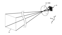
- FIG. 2A is a schematic diagram illustrating the relationship between the light receiving section 16, the light receiving optical system 15, and the viewing range 51.
- the viewing range 51 is determined by the size (shape, size, light-receiving area) of the light-receiving region of the light-receiving section 16 and the focal length of the light-receiving optical system 15.
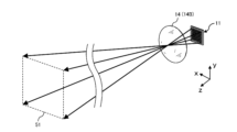
- FIG. 2B is a schematic diagram illustrating the relationship between the light emitting unit 11, the light projection optical system 14, and the viewing range 51.
- the viewing range 51 is determined by the size (shape, size, light receiving area) of the light emitting region of the light emitting unit 11 and the focal length of the light projecting optical system 14.
- the size of the viewing range 51 is restricted by the size of the light receiving section 16 and the size of the light emitting section 11. Therefore, the viewing range when using ready-made products as the light receiving section 16 and the light emitting section 11, for example, does not necessarily match the purpose or application of the system to which the measuring device 100 is applied. Furthermore, depending on the purpose and application of the measuring device 100, there is a need to increase measurement accuracy in a specific visual field range compared to other visual field ranges. For example, when flash LiDAR is applied to AD or ADAS, there is a need to improve measurement accuracy in a specific field of view such as far away from oncoming traffic. It is necessary to respond flexibly to these needs.
- a diffraction grating (diffractive optical element) is used as an element of the light receiving optical system 15 of the light receiver or the light emitting optical system 14 of the light projector, thereby meeting the above-mentioned needs. I'm trying. The specific configuration will be explained below.
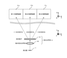
- FIG. 3 shows a light receiver and a viewing range 51 of the light receiver (a first viewing range aligned in the +x direction in the figure) when a diffraction grating (diffraction optical element) is used in the light receiving optical system 15 of the light receiver. 51a, a second viewing range 51b, and a third viewing range 51c).
- the elements of the light receiver are depicted as viewed from a direction perpendicular to the optical axis of the light-receiving section 16 (viewed from the +y side).
- the viewing range 51 is depicted as a view viewed from the direction of the optical axis (a view viewed from the -z side).
- the arrows shown in the figure indicate the direction in which the projector projects light toward each viewing range 51 (first viewing range 51a, second viewing range 51b, third viewing range 51c), which enters the receiver from each viewing range. Represents reflected light caused by light. In this figure, the size of the light receiver is exaggerated.
- the light-receiving optical system 15 includes a diffraction grating 151 on whose surface minute irregularities on the order of a wavelength are periodically formed, and other optical systems 152 (various lenses, various filters, etc.).
- the diffraction grating 151 is a transmission phase grating.
- the reflected light that enters the diffraction grating 151 from the first viewing range 51a (hereinafter referred to as "first reflected light”) is +1st order diffracted light (first order diffracted light).
- the light enters another optical system 152 as light).
- the reflected light that enters the diffraction grating 151 from the second viewing range 51b adjacent to the first viewing range 51a (hereinafter referred to as "second reflected light”) is the 0th order diffracted light (second order is incident on another optical system 152 as diffracted light).
- the reflected light (hereinafter referred to as "third reflected light”) that enters the diffraction grating 151 from the third viewing range 51c adjacent to the second viewing range 51b is -1st order diffracted light (third The light is incident on another optical system 152 as diffracted light of the second order. Then, each reflected light (first reflected light, second reflected light, and third reflected light) that has entered the other optical system 152 is focused on the light receiving section 16.
- each viewing range 51 (first viewing range 51a, second viewing range 51b, third viewing range 51c) can be reduced. Both can be focused on the light receiving section 16. Therefore, the field of view (FOV) of the light receiver can be expanded without expanding the light receiving area of the light receiving section 16 (without increasing the number of light receiving elements).
- the reflected light (diffraction light) from each viewing range 51 is The light will be incident on the same light receiving element of the light receiving section 16. Therefore, when implemented in the measuring device 100, some kind of mechanism is required to distinguish from which viewing range 51 the reflected light is received.
- the above mechanism projects light from the projector to each viewing range 51 (first viewing range 51a, second viewing range 51b, third viewing range 51c) at different timings for each viewing range 51.
- the arithmetic unit 150 controls the light projection control device 112 so that light is projected from the light projector at different timings for each viewing range 51, and the light receiving element of the light receiving unit 16 receives reflected light. Based on the timing, it is determined which viewing range 51 the reflected light comes from (hereinafter referred to as the "first method").
- the projector illuminates a part of each viewing range 51 (a part of the first viewing range 51a, a part of the first viewing range 51a where the light does not enter the same light-receiving element, (a partial area of the second visual field range 51b and a partial area of the third visual field range 51c), and the light may be emitted simultaneously for each selected area (hereinafter referred to as the "second method").
- the second method since light can be received simultaneously for each of the above viewing ranges 51, all the viewing ranges 51 (the first viewing range 51a, the second viewing range 51b, the third viewing range 51c) can reduce the time required for light projection (scan speed).
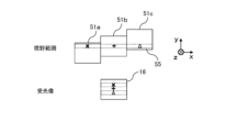
- the projector simultaneously projects light onto a band-shaped region 55 spanning a first viewing range 51a, a second viewing range 51b, and a third viewing range 51c.
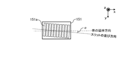
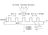
- FIG. 4B the direction in which the slits 1511 of the diffraction grating 151 (one unit of the grating (FIG. 6) consisting of convex portions and concave portions) is aligned with the extension of the above-mentioned band-shaped region 55 is shown in FIG.
- the diffraction grating 151 may be arranged in a positional relationship rotated by a predetermined angle ⁇ around the optical axis (Z axis in FIG. 4B) with respect to the direction (hereinafter referred to as the "third method"). ).
- the thickness (distance (width) in the y direction in the figure) of the above-mentioned strip-shaped area 55 is set so that the reflected light from different viewing ranges 51 does not enter the light receiving section 16 at the same time. (in the example shown in the figure, the amount of deviation (step difference) in the y direction of adjacent viewing ranges 51).
- FIG. 5A is an example of the visual field range 51 and an image of reflected light focused on the light receiving section 16 (light-receiving image) when the third method is adopted. As shown in the figure, reflected light from each viewing range 51 (+1st order diffracted light, 0th order diffracted light, -1st order diffracted light) is focused on different light receiving elements of the light receiving section 16.
- the optical axis of the diffraction grating 151 is made to coincide with the extending direction of the strip-shaped region 55, as shown in FIG. (reflected light from the strip-shaped area 55 of each viewing range 51) overlaps and is condensed at the same time.
- light can be emitted and received at the same time for the strip-shaped area 55 extending from the first viewing range 51a to the third viewing range 51c, and the light projection for the entire viewing range 51 can be performed.
- the time (scanning speed) can be shortened.
- the field of view (FOV) of the light receiver can be improved without expanding the light-receiving area of the light-receiving section 16 (without increasing the number of light-receiving elements). can be easily extended from the first viewing range 51a to the third viewing range 51c.
- M ⁇ d ⁇ sin ⁇ ...Formula 1 Therefore, by selecting the grating pitch d and the wavelength ⁇ of the incident light, the field of view (FOV) of the light receiver can be adjusted.
- the diffraction angle ⁇ of the diffraction grating 151 is set to 40° (the viewing angle of the first viewing range 51a is +20° to +60°, and the viewing angle of the second viewing range 51b is 40°).
- the grating pitch d may be set to 1.4 ⁇ m.
- FIG. 6 is a diagram illustrating parameters that determine the characteristics of the diffraction grating 151.
- the diffraction efficiency (transmittance) of the diffraction grating 151 is determined by the grating density shown in the figure (the proportion occupied by the convex portions 1511a in the slits 1511) and the height of the convex portions 1511a. Therefore, by adjusting these values, each reflected light (+1st order diffracted light, 0 It is possible to adjust the diffraction efficiency (the amount of reflected light incident on the light receiving section 16) of the next diffracted light (-1st order diffracted light).
- the amount of diffracted light when the height of the convex portion 1511a is 0.905 ⁇ m and the grating density is 0.65 is, assuming that the amount of incident light is 100%.
- the amount of +1st order diffracted light is 31.1%
- the amount of 0th order diffracted light is 33.1%
- the amount of ⁇ 1st order diffracted light is 31.3%.
- the viewing range 51 (light receiving range) of the light receiver can be adjusted to the viewing range required by the system to which it is applied.
- the values of parameters such as the refractive index, grating density, and height of the convex portion 1511a of the diffraction grating 151, each diffracted light (+1st order diffracted light, 0th order diffracted light) emitted from the diffraction grating 151 can be adjusted.
- -1st order diffracted light can be adjusted.
- the measuring device 100 of this embodiment can flexibly respond to the specifications required by the system to which it is applied.
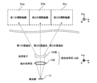
- FIG. 7 shows a light projector and a field of view of the light projector when a diffraction grating 141 having the same configuration as the diffraction grating 151 used in the light receiving optical system 15 described above is used in the light projecting optical system 14 of the light projector of the measuring device 100.
- 51 light projection range
- 51a first viewing range 51a, second viewing range 51b, third viewing range 51c.
- the elements of the light projector (light projecting optical system 14 and light emitting section 11) are depicted as viewed from a direction perpendicular to the optical axis of the light emitting section 11 (viewed from the +y side).
- each viewing range 51 is depicted as a view viewed from the direction of the optical axis (a view viewed from the -z side).
- the arrows shown in the figure represent the correspondence between each diffracted light beam emitted from the projector and each viewing range 51 (first viewing range 51a, second viewing range 51b, third viewing range 51c).
- the size of the projector is exaggerated.
- the light projection optical system 14 includes a diffraction grating 141 and other optical systems 142 (various lenses, various filters, etc.). As shown in the figure, the light emitted from the light emitting unit 11 passes through another optical system 142 and enters the diffraction grating 141, and as a result, the +1st-order light is directed from the diffraction grating 141 toward the first viewing range 51a. Diffracted light, 0th-order diffracted light toward the second viewing range 51b, and -1st-order diffracted light toward the third viewing range 51c are emitted.
- the field of view (FOV) of the light projector can be increased without expanding the light emitting area of the light emitting unit 11 (without increasing the number of light emitting elements). , can be easily extended to a range from the first visual field range 51a to the third visual field range 51c.
- the viewing range 51 of the projector can be adjusted by selecting the grating pitch d of the diffraction grating 141 and the wavelength ⁇ of the incident light.
- the values of parameters such as the refractive index, grating density, and height of the convex portion of the diffraction grating 141, each diffracted light (+1st-order diffracted light, 0th-order diffracted light, -1st-order diffracted light) ) can be adjusted. Therefore, it is possible to flexibly respond to the specifications required by the system to which the measuring device 100 is applied.
- a diffraction grating (diffraction optical element) is used as an element of the light receiving optical system 15 of the light receiver.
- a diffraction grating (diffraction optical element) is used as an element of the light projection optical system 14 of the light projector.
- the above-mentioned needs are met by using an optical element having a prism structure as an element of the light receiving optical system 15B of the light receiver or the light projecting optical system 14B of the light emitter. We are taking measures. The specific configuration will be explained below.
- FIG. 8 shows a light receiver and a viewing range 51 of the light receiver (a first viewing range lined up in the + 51a, a second viewing range 51b, and a third viewing range 51c).
- the same components as those shown in FIG. 3 are denoted by the same reference numerals, and the description thereof will be omitted.
- the light receiving optical system 15B includes an optical element 151B having a prism structure and other optical systems 152 (various lenses, various filters, etc.).
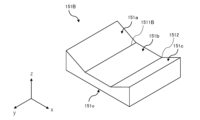
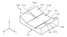
- FIG. 9A shows an external perspective view of the optical element 151B.
- the optical element 151B has a first entrance surface 151a, a second entrance surface 151b, and a third entrance surface 151c.
- the first incident surface 151a is formed on the upper surface side (+z side in the figure) of the optical element 151B, and the first reflected light from the first viewing range 51a is incident on the first incident surface 151a.
- the second incident surface 151b is formed continuously to the first incident surface 151a, and the second reflected light from the second visual field range 51b continuous to the first visual field range 51a is reflected from the second incident surface 151b. incident on .
- the third entrance surface 151c is formed continuously to the second entrance surface 151b, and the third reflected light from the third viewing range 51c that is continuous to the second viewing range 51b is reflected from the third entrance surface 151c. incident on .
- the optical element 151B receives the refracted light of the first reflected light, the transmitted light of the second reflected light, and the refracted light of the third reflected light on the lower surface side (-z side in the figure) of the optical element 151B. It has an output surface 151o that outputs light to the portion 16.
- the first entrance surface 151a, the second entrance surface 151b, the third entrance surface 151c, and the exit surface 151o are all flat surfaces.
- FIG. 9B is a side view of the optical element 151B viewed from the +y side of FIG. 9A.
- the second entrance surface 151b is parallel to the exit surface 151o.
- the first entrance surface 151a is inclined toward the +z side at an inclination angle ⁇ 1 with respect to the second entrance surface 151b, with the first boundary line 1511B between the second entrance surface 151b and the second entrance surface 151b as a fold.
- a prism structure is formed on one end side (-x side).
- the third entrance surface 151c is inclined toward the +z side at an inclination angle ⁇ 2 with the second boundary line 1512 between the second entrance surface 151b and the second entrance surface 151b as a fold line.
- a prism structure is formed on the other end side (+x side) of 151B.
- the optical axis of the optical element 151B (a line passing through the center line of the second entrance surface 151b and perpendicular to the exit surface 151o (normal to the exit surface 151o),
- the optical axis 1515 is arranged to coincide with the optical axes of the other optical system 152 and the light receiving section 16 .
- the first reflected light from the first viewing range 51a enters the first incident surface 151a of the optical element 151B and is refracted, and then exits from the exit surface 151o and is transmitted to other optical devices.
- the light passes through the system 152 and is focused on the light receiving section 16 .
- the second reflected light from the second viewing range 51b enters the second entrance surface 151b of the optical element 151B, then exits from the exit surface 151o, passes through another optical system 152, and enters the light receiving section 16. The light is focused.
- the third reflected light from the third viewing range 51c enters the third entrance surface 151c of the optical element 151B and is refracted, then exits from the exit surface 151o, passes through another optical system 152, and is received. The light is focused on the portion 16.
- each viewing range 51 (first viewing range 51a, second viewing range 51b, third viewing range 51c) can be reduced. Both can be focused on the light receiving section 16. Therefore, the field of view (FOV) of the light receiver can be expanded without expanding the light receiving area of the light receiving section 16 (without increasing the number of light receiving elements).
- each viewing range 51 (the first viewing range 51a, the second viewing range 51b, and the third viewing range 51c) is reflected from the light receiving unit 16.
- the light will be incident on the same light-receiving element. Therefore, when implemented in the measuring device 100B, some kind of mechanism is required to distinguish from which viewing range 51 the reflected light is received.
- the above mechanism may use, for example, the first method and the second method described above.
- the projector simultaneously projects light onto a band-shaped region 55 spanning a first viewing range 51a, a second viewing range 51b, and a third viewing range 51c.
- the first entrance surface 151a is further inclined with respect to the second entrance surface 151b at an inclination angle ⁇ 1 along the first boundary line 1511B.
- the third entrance surface 151c is further separated from the first entrance surface 151a along the second boundary line 1512 with respect to the second entrance surface 151b. It is tilted in the opposite direction at an angle of inclination ⁇ 2 (hereinafter referred to as the "fourth method").
- the first entrance surface 151a may be tilted by rotating around an axis 1516a parallel to the x-axis set within the plane of the first entrance surface 151a, or It may also be tilted by rotating about an axis 1517a extending in the direction.
- the third entrance surface 151c may be tilted by rotating around an axis 1516b parallel to the x-axis set within the plane of the third entrance surface 151c, or may be tilted in the same direction as the x-axis. It may be tilted by rotating about the extending axis 1517b.
- an example of the visual field range 51 and the image (received light image) of the reflected light focused on the light receiving section 16 is the same as that in FIG. 5A. As shown in the figure, the reflected light from each viewing range 51 is focused on different light receiving elements of the light receiving section 16.
- light can be emitted and received simultaneously for the strip-shaped area 55 extending from the first viewing range 51a to the third viewing range 51c, and the light projection for the entire viewing range 51 can be performed.
- the time (scanning speed) can be shortened.
- the light-receiving area of the light-receiving section 16 can be expanded (without increasing the number of light-receiving elements).
- the field of view (FOV) can be easily expanded from the first field of view 51a to the third field of view 51c.
- the light receiving range first viewing range 51a and third viewing range 51c
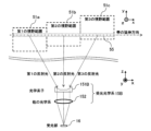
- FIG. 11 shows a light projector and a field of view range 51 (light projection range)
- FIG. 4 is a diagram illustrating the relationship between a first visual range 51a, a second visual range 51b, and a third visual range 51c).
- the same components as those shown in FIG. 7 are denoted by the same reference numerals, and the description thereof will be omitted.
- the arrows shown in the figure represent the correspondence between the light emitted from the optical element 141B and each viewing range 51 (first viewing range 51a, second viewing range 51b, and third viewing range 51c).
- the light projection optical system 14B includes an optical element 141B having a prism structure and other optical systems 142 (various lenses, various filters, etc.).
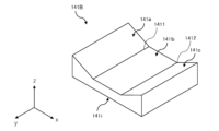
- FIG. 12A shows an external perspective view of the optical element 141B.
- the optical element 141B has an entrance surface 141i on the lower surface side (-z side in the figure) of the optical element 141B, into which light from the light emitting section 11 enters.
- the optical element 141B has a first output surface 141a, a second output surface 141b, and a third output surface 141c.
- the first output surface 141a outputs the light incident on the input surface 141i from the light emitting section 11 toward the first viewing range 51a toward the upper surface side (+z side in the figure) of the optical element 141B.
- the second output surface 141b is formed continuously from the first output surface 141a, and outputs the light that is incident on the input surface 141i from the light emitting section 11 toward the second viewing range 51b.
- the third output surface 141c is formed continuously with the second output surface 141b, and outputs the light that is incident on the input surface 141i from the light emitting section 11 toward the third viewing range 51c.
- the entrance surface 141i, the first exit surface 141a, the second exit surface 141b, and the third exit surface 141c are all flat surfaces.
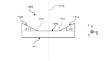
- FIG. 12B is a side view of the optical element 141B viewed from the ⁇ y side of FIG. 9A.
- the entrance surface 141i is parallel to the second exit surface 141b.
- the first exit surface 141a is inclined toward the +z side at an inclination angle ⁇ 1 with respect to the second exit surface 141b, with the first boundary line 1411 between the second exit surface 141b and the second exit surface 141b as a fold.
- a prism structure is formed on one end side (-x side).
- the third exit surface 141c is inclined toward the +z side at an inclination angle ⁇ 2 with the second boundary line 1412 between the second exit surface 141b and the second exit surface 141b as a fold line, thereby increasing the angle of the optical element 141B.
- a prism structure is formed on the other end side (+x side).
- the optical element 141B has an optical axis (a line passing through the center line of the second exit surface 141b and perpendicular to the entrance surface 141i (normal to the entrance surface 141i, denoted by the reference numeral in FIG. 12B).
- the optical axis 1415) is arranged to coincide with the optical axes of the other optical system 142 and the light emitting section 11.
- the light emitted from the light emitting section 11 passes through another optical system 142 and enters the optical element 141B.
- the first transmitted light is refracted at the first output surface 141a and goes to the first viewing range 51a
- the first transmitted light is transmitted through the second output surface 141b and goes to the second viewing range 51b.
- the second transmitted light and the third transmitted light that is refracted by the third output surface 141c and directed toward the third viewing range 51c are emitted.
- the field of view (FOV) of the light emitter can be increased without expanding the light emitting area of the light emitting unit 11 (without increasing the number of light emitting elements).
- the light projection range can be adjusted to meet the specifications required by the system to which the measuring device 100B is applied. Able to respond flexibly.
- the case where there are three viewing ranges (light emitting range, light receiving range) (the first viewing range 51a, the second viewing range 51b, and the third viewing range 51c) has been described as an example.
- the disclosure can also be applied to cases where there are two viewing ranges or four or more viewing ranges.
- the configurations of the emitter and the light receiver described above include both of these. It may be applied to the measuring device 100, or only one of them may be applied.
- the viewing range was expanded by using diffracted light of three different orders (+1st order, 0th order, -1st order) of the diffraction grating, but it is possible to expand the viewing range by using diffracted light of orders other than these.
- the viewing range may be expanded.
- the configurations of the light emitter and the light receiver described above include both of these. It may be applied to the measuring device 100B, or only one of them may be applied.
Landscapes
- Physics & Mathematics (AREA)
- Engineering & Computer Science (AREA)
- General Physics & Mathematics (AREA)
- Radar, Positioning & Navigation (AREA)
- Remote Sensing (AREA)
- Electromagnetism (AREA)
- Computer Networks & Wireless Communication (AREA)
- Investigating Or Analysing Materials By Optical Means (AREA)
- Length Measuring Devices By Optical Means (AREA)
Abstract
Description
図3は、受光器の受光光学系15に回折格子(回折光学素子)を用いた場合における、受光器と、受光器の視野範囲51(同図において+xの方向に並ぶ、第1の視野範囲51a、第2の視野範囲51b、第3の視野範囲51c)との関係を説明する図である。同図は、受光器の要素(受光光学系15、受光部16)については、これらを受光部16の光軸に垂直な方向から眺めた図(+y側から眺めた図)として描いている。また同図は、視野範囲51については、上記光軸の方向から眺めた図(-z側から眺めた図)として描いている。同図に示す矢線は、各視野範囲から受光器に入射する、投光器が各視野範囲51(第1の視野範囲51a、第2の視野範囲51b、第3の視野範囲51c)に向けて投光することにより生じる反射光を表す。同図は、受光器のサイズを誇張して描いている。
[数1]
M×λ=d×sinθ ・・・式1
このため、格子ピッチdと入射光の波長λを選択することで、受光器の視野範囲(FOV)を調節することができる。例えば、入射する反射光の波長λが905nmである場合、回折格子151の回折角θを40゜(第1の視野範囲51aの視野角を+20゜~+60゜、第2の視野範囲51bの視野角を±20゜、第3の視野範囲51cの視野角を-20゜~-60゜)とするには、格子ピッチdを1.4μmとすればよい。
図7は、測定装置100の投光器の投光光学系14に、前述の受光光学系15に用いた回折格子151と同様の構成の回折格子141を用いた場合における、投光器と、投光器の視野範囲51(投光範囲)(第1の視野範囲51a、第2の視野範囲51b、第3の視野範囲51c)との関係を説明する図である。同図は、投光器の要素(投光光学系14、及び発光部11)についてはこれらを発光部11の光軸に垂直な方向から眺めた図(+y側から眺めた図)として描いている。また同図は、各視野範囲51については、上記光軸の方向から眺めた図(-z側から眺めた図)として描いている。同図に示す矢線は、投光器から出射した各回折光と各視野範囲51(第1の視野範囲51a、第2の視野範囲51b、第3の視野範囲51c)との対応を表している。同図は、投光器のサイズを誇張して描いている。
図8は、プリズム構造を有する光学素子151Bを受光器の受光光学系15Bに用いた場合における、受光器と、受光器の視野範囲51(同図において+xの方向に並ぶ、第1の視野範囲51a、第2の視野範囲51b、第3の視野範囲51c)との関係を説明する図である。図8に示す構成において、図3に示した構成と同一の構成については同一の符号を付し、その説明を省略する。
図11は、測定装置100Bの投光器の投光光学系14Bに、前述した光学素子151Bと同様の構成の光学素子141Bを用いた場合における、投光器と、投光器の視野範囲51(投光範囲)(第1の視野範囲51a、第2の視野範囲51b、第3の視野範囲51c)との関係を説明する図である。図11に示す構成において、図7に示した構成と同一の構成については同一の符号を付し、その説明を省略する。同図に示す矢線は、光学素子141Bから出射する光と各視野範囲51(第1の視野範囲51a、第2の視野範囲51b、第3の視野範囲51c)との対応を表している。
Claims (30)
- 投光器と、前記投光器が視野範囲に向けて投光することにより生じる反射光を受光する受光器と、を備え、
前記受光器は、受光部と、透過型の回折格子と、を含み、
前記回折格子が、第1の視野範囲からの第1の反射光が第1の次数の回折光として前記受光部に入射し、前記第1の視野範囲に並ぶ第2の視野範囲からの第2の反射光が第2の次数の回折光として前記受光部に入射するように配置されている、
測定装置。 - 請求項1に記載の測定装置であって、
前記投光器は、前記第1の視野範囲と前記第2の視野範囲に向けて、夫々異なるタイミングで投光する、
測定装置。 - 請求項1に記載の測定装置であって、
前記受光部は、複数の受光素子を含み、
前記回折格子は、前記回折格子のスリットの並び方向が、前記第1の視野範囲と前記第2の視野範囲の並び方向に一致するように配置され、
前記投光器は、前記第1の反射光と前記第2の反射光が同じ前記受光素子に入射しない関係となる、前記第1の視野範囲の一部と前記第2の視野範囲の一部に向けて同時に投光する、
測定装置。 - 請求項1に記載の測定装置であって、
前記受光部は、面状に配置された複数の受光素子を含み、
前記投光器は、前記第1の視野範囲から前記第2の視野範囲に亘る帯状の領域を同時に投光し、
前記回折格子は、前記回折格子のスリットの並び方向を、前記第1の反射光と前記第2の反射光が夫々異なる前記受光素子に入射するように、前記帯状の領域の延伸方向に対して当該回折格子の光軸周りに所定角度回転させた位置関係で配置されている、
測定装置。 - 投光器と、前記投光器が視野範囲に向けて投光することにより生じる反射光を受光する受光器と、を備え、
前記受光器は、受光部と、透過型の回折格子と、を含み、
前記回折格子は、
第1の視野範囲からの第1の反射光が+1次の回折光として前記受光部に入射し、
前記第1の視野範囲に並ぶ第2の視野範囲からの第2の反射光が0次の回折光として前記受光部に入射し、
前記第1の視野範囲から前記第2の視野範囲の方向に、前記第2の視野範囲に並ぶ第3の視野範囲からの第3の反射光が-1次の回折光として前記受光部に入射する
ように配置されている、
測定装置。 - 請求項5に記載の測定装置であって、
前記投光器は、前記第1の視野範囲、前記第2の視野範囲、及び前記第3の視野範囲に向けて、夫々異なるタイミングで投光する、
測定装置。 - 請求項5に記載の測定装置であって、
前記受光部は、面状に配置された複数の受光素子を含み、
前記回折格子は、前記回折格子のスリットの並び方向が、前記第1の視野範囲から前記第3の視野範囲の並び方向に一致するように配置され、
前記投光器は、前記第1の反射光、前記第2の反射光、及び前記第3の反射光が、いずれも前記受光素子に入射しない関係となる、前記第1の視野範囲の一部、前記第2の視野範囲の一部、及び前記第3の視野範囲の一部に向けて同時に投光する、
測定装置。 - 請求項5に記載の測定装置であって、
前記受光部は、面状に配置された複数の受光素子を含み、
前記投光器は、前記第1の視野範囲から前記第3の視野範囲に亘る帯状の領域を同時に投光し、
前記回折格子は、前記回折格子のスリットの並び方向を、前記第1の反射光、前記第2の反射光、及び前記第3の反射光が、夫々異なる前記受光素子に入射するように、前記帯状の領域の延伸方向に対して当該回折格子の光軸周りに所定角度回転させた位置関係で配置されている、
測定装置。 - 投光器が視野範囲に向けて投光することにより生じる反射光を受光する受光器であって、
受光部と、透過型の回折格子と、を含み、
前記回折格子が、第1の視野範囲からの第1の反射光が第1の次数の回折光として前記受光部に入射し、前記第1の視野範囲に並ぶ第2の視野範囲からの第2の反射光が第2の次数の回折光として前記受光部に入射するように配置されている、
受光器。 - 投光器が視野範囲に向けて投光することにより生じる反射光を受光する受光器であって、
前記受光器は、受光部と、透過型の回折格子と、を含み、
前記回折格子は、
第1の視野範囲からの第1の反射光が+1次の回折光として前記受光部に入射し、
前記第1の視野範囲に並ぶ第2の視野範囲からの第2の反射光が0次の回折光として前記受光部に入射し、
前記第1の視野範囲から前記第2の視野範囲の方向に、前記第2の視野範囲に並ぶ第3の視野範囲からの第3の反射光が-1次の回折光として前記受光部に入射する
ように配置されている、
受光器。 - 投光器と、前記投光器が視野範囲に向けて投光することにより生じる反射光を受光する受光器と、を備え、
前記投光器は、発光部と、透過型の回折格子と、を含み、
前記回折格子が、前記発光部からの光が当該回折格子を透過することにより生じる第1の次数の回折光を第1の視野範囲に向けて出射し、前記光が当該回折格子を透過することにより生じる第2の次数の回折光を前記第1の視野範囲に並ぶ第2の視野範囲に向けて出射するように配置されている、
測定装置。 - 投光器と、前記投光器が視野範囲に向けて投光することにより生じる反射光を受光する受光器と、を備え、
前記投光器は、発光部と、透過型の回折格子と、を含み、
前記回折格子が、
前記発光部からの光が当該回折格子を透過することにより生じる+1次の回折光を、第1の視野範囲に向けて出射し、
前記光が当該回折格子を透過することにより生じる0次の回折光を、前記第1の視野範囲に並ぶ第2の視野範囲に向けて出射し、
前記光が当該回折格子を透過することにより生じる-1次の回折光を、前記第1の視野範囲から前記第2の視野範囲の方向に、前記第2の視野範囲に並ぶ第3の視野範囲に向けて出射する
ように配置されている、
測定装置。 - 視野範囲に向けて投光する投光器であって、
発光部と、透過型の回折格子と、を含み、
前記回折格子が、
前記発光部からの光が当該回折格子を透過することにより生じる第1の次数の回折光を第1の視野範囲に向けて出射し、
前記光が当該回折格子を透過することにより生じる第2の次数の回折光を前記第1の視野範囲に並ぶ第2の視野範囲に向けて出射する
ように配置されている、
投光器。 - 視野範囲に向けて投光する投光器であって、
発光部と、透過型の回折格子と、を含み、
前記回折格子が、
前記発光部からの光が当該回折格子を透過することにより生じる+1次の回折光を、第1の視野範囲に向けて出射し、
前記光が当該回折格子を透過することにより生じる0次の回折光を、前記第1の視野範囲に並ぶ第2の視野範囲に向けて出射し、
前記光が当該回折格子を透過することにより生じる-1次の回折光を、前記第1の視野範囲から前記第2の視野範囲の方向に、前記第2の視野範囲に並ぶ第3の視野範囲に向けて出射する
ように配置されている、
投光器。 - 投光器と、前記投光器が視野範囲に向けて投光することにより生じる反射光を受光する受光器と、を備え、
前記受光器は、受光部と、透過型の光学素子と、を含み、
前記光学素子は、
第1の視野範囲からの第1の反射光が入射する第1の入射面と、
前記第1の入射面に連続して形成され、前記第1の視野範囲に連続する第2の視野範囲からの第2の反射光が入射する第2の入射面と、
前記第1の反射光及び前記第2の反射光を、前記受光部に出射する出射面と、
を有し、
前記第1の入射面、前記第2の入射面、及び前記出射面は、いずれも平坦面であり、
前記第2の入射面は、前記第1の入射面に対して前記第1の入射面との境界線を折り目として傾斜している、
測定装置。 - 請求項15に記載の測定装置であって、
前記投光器は、前記第1の視野範囲と前記第2の視野範囲に向けて、夫々異なるタイミングで投光する、
測定装置。 - 請求項15に記載の測定装置であって、
前記受光部は、複数の受光素子を含み、
前記投光器は、前記第1の反射光及び前記第2の反射光が夫々異なる前記受光素子に入射するように、前記第1の視野範囲と前記第2の視野範囲に向けて投光する、
測定装置。 - 請求項15に記載の測定装置であって、
前記受光部は、面状に配置された複数の受光素子を含み、
前記第2の入射面は、更に、前記第1の入射面に対して前記境界線に沿って傾斜し、
前記投光器は、前記第1の反射光及び前記第2の反射光が夫々前記受光部の異なる前記受光素子に入射するように、前記第1の視野範囲から前記第2の視野範囲に亘る帯状の領域を同時に投光する、
測定装置。 - 投光器と、前記投光器が視野範囲に向けて投光することにより生じる反射光を受光する受光器と、を備え、
前記受光器は、受光部と、透過型の光学素子と、を含み、
前記光学素子は、
第1の視野範囲からの第1の反射光が入射する第1の入射面と、
前記第1の入射面に連続して形成され、第2の視野範囲からの第2の反射光が入射する第2の入射面と、
前記第2の入射面に連続して形成され、第3の視野範囲からの第3の反射光が入射する第3の入射面と、
前記第1の反射光、前記第2の反射光、及び前記第3の反射光を、前記受光部に出射する出射面と、
を有し、
前記第1の入射面、前記第2の入射面、前記第3の入射面、及び前記出射面は、いずれも平坦面であり、
前記第1の入射面は、前記第2の入射面に対して前記第2の入射面との第1の境界線を折り目として傾斜し、
前記第3の入射面は、前記第2の入射面に対して前記第2の入射面との第2の境界線を折り目として傾斜している、
測定装置。 - 請求項19に記載の測定装置であって、
前記投光器は、前記第1の視野範囲、前記第2の視野範囲、及び前記第3の視野範囲に向けて、夫々異なるタイミングで投光する、
測定装置。 - 請求項19に記載の測定装置であって、
前記受光部は複数の受光素子を含み、
前記投光器は、前記第1の反射光、前記第2の反射光、及び前記第3の反射光が夫々、異なる前記受光素子に入射するように、前記第1の視野範囲、前記第2の視野範囲、及び前記第3の視野範囲に向けて投光する、
測定装置。 - 請求項19に記載の測定装置であって、
前記受光部は、面状に配置された複数の受光素子を含み、
前記第1の入射面は、更に、前記第2の入射面に対し、前記第1の境界線に沿って傾斜し、
前記第3の入射面は、更に、前記第2の入射面に対し、前記第2の境界線に沿って、前記第1の入射面とは逆の方向に傾斜し、
前記投光器は、前記第1の反射光、前記第2の反射光、及び前記第3の反射光が夫々前記受光部の異なる前記受光素子に入射するように、前記第1の視野範囲から前記第3の視野範囲に亘る帯状の領域を同時に投光する、
測定装置。 - 投光器が視野範囲に向けて投光することにより生じる反射光を受光する受光器であって、
受光部と、透過型の光学素子と、を含み、
前記光学素子は、
第1の視野範囲からの第1の反射光が入射する第1の入射面と、
前記第1の入射面に連続して形成され、前記第1の視野範囲に連続する第2の視野範囲からの第2の反射光が入射する第2の入射面と、
前記第1の反射光及び前記第2の反射光を、前記受光部に出射する出射面と、
を有し、
前記第1の入射面、前記第2の入射面、及び前記出射面は、いずれも平坦面であり、
前記第2の入射面は、前記第1の入射面に対して前記第1の入射面との境界線を折り目として傾斜している、
受光器。 - 請求項23に記載の受光器であって、
前記受光部は、面状に配置された複数の受光素子を含み、
前記第2の入射面は、更に、前記第1の入射面に対して前記境界線に沿って傾斜している、
受光器。 - 投光器が視野範囲に向けて投光することにより生じる反射光を受光する受光器であって、
受光部と、透過型の光学素子と、を含み、
前記光学素子は、
第1の視野範囲からの第1の反射光が入射する第1の入射面と、
前記第1の入射面に連続して形成され、第2の視野範囲からの第2の反射光が入射する第2の入射面と、
前記第2の入射面に連続して形成され、第3の視野範囲からの第3の反射光が入射する第3の入射面と、
前記第1の反射光、前記第2の反射光、及び前記第3の反射光を、前記受光部に出射する出射面と、
を有し、
前記第1の入射面、前記第2の入射面、前記第3の入射面、及び前記出射面は、いずれも平坦面であり、
前記第1の入射面は、前記第2の入射面に対して前記第2の入射面との第1の境界線を折り目として傾斜し、
前記第3の入射面は、前記第2の入射面に対して前記第2の入射面との第2の境界線を折り目として傾斜している、
受光器。 - 請求項25に記載の受光器であって、
前記受光部は、面状に配置された複数の受光素子を含み、
前記第1の入射面は、更に、前記第2の入射面に対し、前記第1の境界線に沿って傾斜し、
前記第3の入射面は、更に、前記第2の入射面に対し、前記第2の境界線に沿って、前記第1の入射面とは逆の方向に傾斜する、
受光器。 - 投光器と、前記投光器が視野範囲に向けて投光することにより生じる反射光を受光する受光器と、を備え、
前記投光器は、発光部と、透過型の光学素子と、を含み、
前記光学素子は、
前記発光部からの光が入射する入射面と、
前記入射面に入射する光を第1の視野範囲に向けて出射する第1の出射面と、
前記入射面に入射する光を第2の視野範囲に向けて出射する第2の出射面と、
を有し、
前記入射面、前記第1の出射面、及び前記第2の出射面は、いずれも平坦面であり、
前記第2の出射面は、前記第1の出射面に対して前記第2の出射面との境界線を折り目として傾斜している、
測定装置。 - 投光器と、前記投光器が視野範囲に向けて投光することにより生じる反射光を受光する受光器と、を備え、
前記投光器は、発光部と、透過型の光学素子と、を含み、
前記光学素子は、
前記発光部からの光が入射する入射面と、
前記入射面に入射する光を第1の視野範囲に向けて出射する第1の出射面と、
前記入射面に入射する光を第2の視野範囲に向けて出射する第2の出射面と、
前記入射面に入射する光を第3の視野範囲に向けて出射する第3の出射面と、
を有し、
前記入射面、前記第1の出射面、前記第2の出射面、及び前記第3の出射面は、いずれも平坦面であり、
前記第1の出射面は、前記第2の出射面に対して前記第2の出射面との第1の境界線を折り目として傾斜し、
前記第3の出射面は、前記第2の出射面に対して前記第2の出射面との第2の境界線を折り目として傾斜している、
測定装置。 - 視野範囲に向けて投光する投光器であって、
発光部と、透過型の光学素子と、を含み、
前記光学素子は、
前記発光部からの光が入射する入射面と、
前記入射面に入射する光を第1の視野範囲に向けて出射する第1の出射面と、
前記入射面に入射する光を第2の視野範囲に向けて出射する第2の出射面と、
を有し、
前記入射面、前記第1の出射面、及び前記第2の出射面は、いずれも平坦面であり、
前記第2の出射面は、前記第1の出射面に対して前記第2の出射面との境界線を折り目として傾斜している、
投光器。 - 視野範囲に向けて投光する投光器であって、
発光部と、透過型の光学素子と、を含み、
前記光学素子は、
前記発光部からの光が入射する入射面と、
前記入射面に入射する光を第1の視野範囲に向けて出射する第1の出射面と、
前記入射面に入射する光を第2の視野範囲に向けて出射する第2の出射面と、
前記入射面に入射する光を第3の視野範囲に向けて出射する第3の出射面と、
を有し、
前記入射面、前記第1の出射面、前記第2の出射面、及び前記第3の出射面は、いずれも平坦面であり、
前記第1の出射面は、前記第2の出射面に対して前記第2の出射面との第1の境界線を折り目として傾斜し、
前記第3の出射面は、前記第2の出射面に対して前記第2の出射面との第2の境界線を折り目として傾斜している、
投光器。
Priority Applications (1)
| Application Number | Priority Date | Filing Date | Title |
|---|---|---|---|
| CN202380056222.2A CN119546977A (zh) | 2022-07-28 | 2023-07-24 | 测定装置、受光器以及投光器 |
Applications Claiming Priority (4)
| Application Number | Priority Date | Filing Date | Title |
|---|---|---|---|
| JP2022-120205 | 2022-07-28 | ||
| JP2022-120204 | 2022-07-28 | ||
| JP2022120205A JP7849242B2 (ja) | 2022-07-28 | 2022-07-28 | 測定装置 |
| JP2022120204A JP7849241B2 (ja) | 2022-07-28 | 2022-07-28 | 測定装置、及び受光器 |
Publications (1)
| Publication Number | Publication Date |
|---|---|
| WO2024024745A1 true WO2024024745A1 (ja) | 2024-02-01 |
Family
ID=89706638
Family Applications (1)
| Application Number | Title | Priority Date | Filing Date |
|---|---|---|---|
| PCT/JP2023/027061 Ceased WO2024024745A1 (ja) | 2022-07-28 | 2023-07-24 | 測定装置、受光器、及び投光器 |
Country Status (2)
| Country | Link |
|---|---|
| CN (1) | CN119546977A (ja) |
| WO (1) | WO2024024745A1 (ja) |
Citations (9)
| Publication number | Priority date | Publication date | Assignee | Title |
|---|---|---|---|---|
| JPH03199931A (ja) * | 1989-12-27 | 1991-08-30 | Nippon Arefu:Kk | 光学センサ |
| JPH04147019A (ja) * | 1990-10-11 | 1992-05-20 | Nippon Arefu:Kk | 光学センサ |
| JPH07270602A (ja) * | 1994-03-31 | 1995-10-20 | Omron Corp | 受光用レンズ,受光装置,これらを用いた光電センサおよびレーザ・レーダ,ならびにレーザ・レーダを搭載した車両 |
| JPH08220230A (ja) * | 1994-12-14 | 1996-08-30 | Seiko Epson Corp | 光センシング装置 |
| DE102018133302A1 (de) * | 2018-12-21 | 2020-06-25 | Valeo Schalter Und Sensoren Gmbh | Optische Vorrichtung und optische Sensoreinrichtung mit einer solchen Vorrichtung und Kraftfahrzeug mit einer solchen optischen Sensoreinrichtung |
| CN211426796U (zh) * | 2019-10-18 | 2020-09-04 | 深圳奥锐达科技有限公司 | 一种离轴扫描距离测量系统 |
| JP2021015112A (ja) * | 2020-03-25 | 2021-02-12 | Dolphin株式会社 | 光走査装置、物体検出装置、光検出装置、光走査方法、物体検出方法及びプログラム |
| CN113156460A (zh) * | 2020-01-23 | 2021-07-23 | 华为技术有限公司 | 一种飞行时间tof传感模组及电子设备 |
| JP2022503383A (ja) * | 2018-06-07 | 2022-01-12 | バラハ ピーティーワイ リミテッド | 光ビーム導波器 |
-
2023
- 2023-07-24 CN CN202380056222.2A patent/CN119546977A/zh active Pending
- 2023-07-24 WO PCT/JP2023/027061 patent/WO2024024745A1/ja not_active Ceased
Patent Citations (9)
| Publication number | Priority date | Publication date | Assignee | Title |
|---|---|---|---|---|
| JPH03199931A (ja) * | 1989-12-27 | 1991-08-30 | Nippon Arefu:Kk | 光学センサ |
| JPH04147019A (ja) * | 1990-10-11 | 1992-05-20 | Nippon Arefu:Kk | 光学センサ |
| JPH07270602A (ja) * | 1994-03-31 | 1995-10-20 | Omron Corp | 受光用レンズ,受光装置,これらを用いた光電センサおよびレーザ・レーダ,ならびにレーザ・レーダを搭載した車両 |
| JPH08220230A (ja) * | 1994-12-14 | 1996-08-30 | Seiko Epson Corp | 光センシング装置 |
| JP2022503383A (ja) * | 2018-06-07 | 2022-01-12 | バラハ ピーティーワイ リミテッド | 光ビーム導波器 |
| DE102018133302A1 (de) * | 2018-12-21 | 2020-06-25 | Valeo Schalter Und Sensoren Gmbh | Optische Vorrichtung und optische Sensoreinrichtung mit einer solchen Vorrichtung und Kraftfahrzeug mit einer solchen optischen Sensoreinrichtung |
| CN211426796U (zh) * | 2019-10-18 | 2020-09-04 | 深圳奥锐达科技有限公司 | 一种离轴扫描距离测量系统 |
| CN113156460A (zh) * | 2020-01-23 | 2021-07-23 | 华为技术有限公司 | 一种飞行时间tof传感模组及电子设备 |
| JP2021015112A (ja) * | 2020-03-25 | 2021-02-12 | Dolphin株式会社 | 光走査装置、物体検出装置、光検出装置、光走査方法、物体検出方法及びプログラム |
Also Published As
| Publication number | Publication date |
|---|---|
| CN119546977A (zh) | 2025-02-28 |
Similar Documents
| Publication | Publication Date | Title |
|---|---|---|
| US11977183B2 (en) | 2D scanning high precision LiDAR using combination of rotating concave mirror and beam steering devices | |
| US7193204B2 (en) | Multi-track optical encoder employing beam divider | |
| JP2022022361A (ja) | 小角度発散を伴うvcselアレイlidar送信機 | |
| JP7565342B2 (ja) | ソリッドステートlidarシステム用のプロジェクタ | |
| US20110222073A1 (en) | Optical encoder and displacement measurement apparatus having the same | |
| US20080048104A1 (en) | Optical Encoder | |
| RU2467336C2 (ru) | Устройство измерения перемещения и устройство измерения скорости | |
| JP3752538B2 (ja) | 光結合装置 | |
| US10436953B2 (en) | Arched collimating lens forming a disk-like illumination | |
| US20240411146A1 (en) | Device for emitting a light beam and partial beam splitter | |
| WO2024024745A1 (ja) | 測定装置、受光器、及び投光器 | |
| JP2002243503A (ja) | 光学式エンコーダ | |
| JP2024017518A (ja) | 測定装置、受光器、及び投光器 | |
| JP2024017519A (ja) | 測定装置、受光器、及び投光器 | |
| CN113767300B (zh) | 测距系统 | |
| JP5454373B2 (ja) | エンコーダ | |
| JP3639378B2 (ja) | 光学式エンコーダ | |
| EP4446778A1 (en) | Improved lidar imaging device | |
| JP2023181650A (ja) | レーザレーダおよび受光光学系 | |
| WO2023153438A1 (ja) | 投光器、受光器、及び測定装置 | |
| JP2000121388A (ja) | 光学式エンコーダ | |
| JP2564419B2 (ja) | 光学式測長装置 | |
| KR20240113427A (ko) | 광출력 모듈 및 이를 포함하는 자동차 및 그 제어 방법 | |
| JP2005291794A (ja) | 光学式エンコーダ | |
| CN118843804A (zh) | 用于发射光束的装置和部分分束器 |
Legal Events
| Date | Code | Title | Description |
|---|---|---|---|
| 121 | Ep: the epo has been informed by wipo that ep was designated in this application |
Ref document number: 23846475 Country of ref document: EP Kind code of ref document: A1 |
|
| WWE | Wipo information: entry into national phase |
Ref document number: 202380056222.2 Country of ref document: CN |
|
| WWP | Wipo information: published in national office |
Ref document number: 202380056222.2 Country of ref document: CN |
|
| NENP | Non-entry into the national phase |
Ref country code: DE |
|
| 122 | Ep: pct application non-entry in european phase |
Ref document number: 23846475 Country of ref document: EP Kind code of ref document: A1 |