WO2024024482A1 - コネクタ装置 - Google Patents
コネクタ装置 Download PDFInfo
- Publication number
- WO2024024482A1 WO2024024482A1 PCT/JP2023/025478 JP2023025478W WO2024024482A1 WO 2024024482 A1 WO2024024482 A1 WO 2024024482A1 JP 2023025478 W JP2023025478 W JP 2023025478W WO 2024024482 A1 WO2024024482 A1 WO 2024024482A1
- Authority
- WO
- WIPO (PCT)
- Prior art keywords
- housing
- fitting
- base member
- movable member
- guide
- Prior art date
- Legal status (The legal status is an assumption and is not a legal conclusion. Google has not performed a legal analysis and makes no representation as to the accuracy of the status listed.)
- Ceased
Links
Images







Classifications
-
- H—ELECTRICITY
- H01—ELECTRIC ELEMENTS
- H01R—ELECTRICALLY-CONDUCTIVE CONNECTIONS; STRUCTURAL ASSOCIATIONS OF A PLURALITY OF MUTUALLY-INSULATED ELECTRICAL CONNECTING ELEMENTS; COUPLING DEVICES; CURRENT COLLECTORS
- H01R13/00—Details of coupling devices of the kinds covered by groups H01R12/70 or H01R24/00 - H01R33/00
- H01R13/62—Means for facilitating engagement or disengagement of coupling parts or for holding them in engagement
- H01R13/629—Additional means for facilitating engagement or disengagement of coupling parts, e.g. aligning or guiding means, levers, gas pressure electrical locking indicators, manufacturing tolerances
- H01R13/631—Additional means for facilitating engagement or disengagement of coupling parts, e.g. aligning or guiding means, levers, gas pressure electrical locking indicators, manufacturing tolerances for engagement only
-
- H—ELECTRICITY
- H01—ELECTRIC ELEMENTS
- H01R—ELECTRICALLY-CONDUCTIVE CONNECTIONS; STRUCTURAL ASSOCIATIONS OF A PLURALITY OF MUTUALLY-INSULATED ELECTRICAL CONNECTING ELEMENTS; COUPLING DEVICES; CURRENT COLLECTORS
- H01R13/00—Details of coupling devices of the kinds covered by groups H01R12/70 or H01R24/00 - H01R33/00
- H01R13/62—Means for facilitating engagement or disengagement of coupling parts or for holding them in engagement
- H01R13/629—Additional means for facilitating engagement or disengagement of coupling parts, e.g. aligning or guiding means, levers, gas pressure electrical locking indicators, manufacturing tolerances
- H01R13/631—Additional means for facilitating engagement or disengagement of coupling parts, e.g. aligning or guiding means, levers, gas pressure electrical locking indicators, manufacturing tolerances for engagement only
- H01R13/6315—Additional means for facilitating engagement or disengagement of coupling parts, e.g. aligning or guiding means, levers, gas pressure electrical locking indicators, manufacturing tolerances for engagement only allowing relative movement between coupling parts, e.g. floating connection
-
- H—ELECTRICITY
- H01—ELECTRIC ELEMENTS
- H01R—ELECTRICALLY-CONDUCTIVE CONNECTIONS; STRUCTURAL ASSOCIATIONS OF A PLURALITY OF MUTUALLY-INSULATED ELECTRICAL CONNECTING ELEMENTS; COUPLING DEVICES; CURRENT COLLECTORS
- H01R13/00—Details of coupling devices of the kinds covered by groups H01R12/70 or H01R24/00 - H01R33/00
- H01R13/62—Means for facilitating engagement or disengagement of coupling parts or for holding them in engagement
- H01R13/629—Additional means for facilitating engagement or disengagement of coupling parts, e.g. aligning or guiding means, levers, gas pressure electrical locking indicators, manufacturing tolerances
- H01R13/62905—Additional means for facilitating engagement or disengagement of coupling parts, e.g. aligning or guiding means, levers, gas pressure electrical locking indicators, manufacturing tolerances comprising a camming member
- H01R13/62911—U-shaped sliding element
Definitions
- the present disclosure relates to a connector device.
- Patent Document 1 discloses a standby connector in which an outer housing and an inner housing are attached to a motor case.
- the standby connector is fitted with a mating connector fixed to the inverter case.
- a spring member is attached to the inner housing of the standby connector. Misalignment between the mating connector and the inner housing is absorbed by elastically deforming the spring member.
- the above-described standby connector can absorb positional deviation in a two-dimensional direction perpendicular to the fitting direction of the mating connector and the inner housing. However, it is not possible to absorb positional deviation in a direction parallel to the fitting direction between the mating connector and the inner housing.
- the connector device of the present disclosure was completed based on the above circumstances, and aims to be able to absorb positional deviation in a direction parallel to the fitting direction.
- the connector device of the present disclosure includes: a first base member; a first housing fixed to the first base member; a second base member provided so as to be relatively accessible to the first base member; a second housing that is movable relative to the second base member and that can be fitted into the first housing as the first base member and the second base member approach each other; a movable member attached to the second base member and movable in a direction perpendicular to the fitting direction of the first housing and the second housing between a fitting start position and a fitting completion position,
- the movable member is formed with a guide portion extending diagonally with respect to the fitting direction, In the process in which the first base member and the second base member approach each other, the guide section moves the movable member from the fitting start position to the fitting completion position while moving the first housing and the second base member closer to each other.
- positional deviation in the direction parallel to the fitting direction can be absorbed.
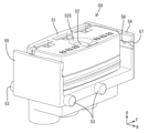
- FIG. 1 is a perspective view showing a state before a first connector and a second connector are fitted together.
- FIG. 2 is a perspective view of the second base member.
- FIG. 3 is a perspective view of the movable member.
- FIG. 4 is a perspective view of the second housing viewed diagonally from above and from the front.
- FIG. 5 is a perspective view of the second housing viewed diagonally from above and behind.
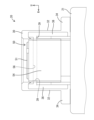
- FIG. 6 is a side view showing the state of the first connector and the second connector before they are fitted together.
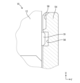
- FIG. 7 is a partially enlarged side view of FIG. 6.
- FIG. 8 is a side view showing a state in which the first housing and the second housing have started to fit together.
- FIG. 9 is a side view showing a state in which the first housing and the second housing are completely fitted.
- FIG. 10 is a partially enlarged side view of FIG. 9.
- FIG. 11 is a side view illustrating a state in which the first housing and the second housing in a properly fitted state are moved to absorb the positional deviation in the fitting direction between the first base member and the second base member.
- FIG. 12 is a partially enlarged side view of FIG. 11.
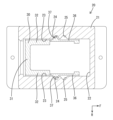
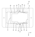
- FIG. 13 is a sectional view taken along the line XX in FIG. 6.
- FIG. 14 is a sectional view taken along the YY line in FIG. 9.
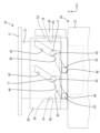
- FIG. 15 is a front view of the second connector in the state shown in FIGS. 1 and 6.
- FIG. FIG. 16 is a partially enlarged perspective view of the state shown in FIG. 15, viewed diagonally from above and behind.
- FIG. 17 is a front view of the second connector in the state shown in FIG. 8.
- FIG. 18 is a partially enlarged side cross-sectional view showing the locked state of the connecting protrusion of the first housing and the connecting groove of the second housing.
- the connector device of the present disclosure includes: (1) A first base member, a first housing fixed to the first base member, a second base member provided so as to be relatively accessible to the first base member, and the second base member a second housing that is movable relative to the first base member and that can be fitted into the first housing as the first base member and the second base member approach each other;
- the movable member is attached and movable between a fitting start position and a fitting completion position in a direction perpendicular to the fitting direction of the first housing and the second housing.
- a guide portion extending diagonally with respect to the fitting direction is formed on the movable member.
- the guide section moves the movable member from the fitting start position to the fitting completion position while moving the first housing and the second base member closer to each other. Guide the housings to fit together.
- the fitting completion position the fitting of the first housing and the second housing is completed, and the first housing and the second housing in the fitting completion state are integrated. It becomes possible to make a relative displacement with respect to the second base member in a direction parallel to the fitting direction.
- the first housing and the second housing are fitted together by the guide portion, and during this period, the movable member moves from the fitting start position to the fitting completion position. Move to.
- the first housing and the second housing are displaced relative to the second base member in a direction parallel to the mating direction while maintaining the mating completion state.
- the first base member and the second base member are relatively displaced in a direction parallel to the fitting direction of the first housing and the second housing.
- the guide portion includes a first guide groove that slides the first cam pin of the first housing during the fitting process of the first housing and the second housing, and the movable member includes a first guide groove that allows the first cam pin of the first housing to come into sliding contact with the first housing.
- a first relief groove is formed that communicates with the terminal end of the guide groove, and when the movable member reaches the mating completion position, the first cam pin enters the first relief groove to prevent the movable member from moving. It is preferable that the member be able to move relative to the member in a direction parallel to the fitting direction.
- both housings are subsequently displaced relative to the second base member.
- the guide portion includes a second guide groove that allows the second cam pin of the second housing to slide into contact with the movable member during the fitting process of the first housing and the second housing.
- a second relief groove is formed that communicates with a terminal end of the second guide groove, and when the movable member reaches the fitting completion position, the second cam pin enters the second relief groove. It is preferable that this makes it possible to move relative to the movable member in a direction parallel to the fitting direction. According to this configuration, since the guide portion extends diagonally with respect to the fitting direction, the second guide groove included in the guide portion also extends diagonally with respect to the fitting direction.
- the fitting direction during the fitting process of both housings is The stroke becomes longer. This makes it possible to avoid a sudden increase in the fitting resistance between both housings, resulting in good workability.
- a pair of the first guide grooves are provided at intervals in a direction orthogonal to the fitting direction, and the first cam pin is arranged in a direction orthogonal to the fitting direction. It is preferable that the guide grooves are arranged at the same interval as the interval between the pair of first guide grooves in the direction in which the first guide grooves are aligned. According to this configuration, by bringing the pair of first cam pins into sliding contact with the pair of first guide grooves, it is possible to prevent the first housing from tilting with respect to the movable member.
- a pair of the second guide grooves are provided at intervals in a direction perpendicular to the fitting direction, and the second cam pin is arranged in the direction perpendicular to the fitting direction. It is preferable that they are arranged at the same interval as the interval between the pair of second guide grooves.
- the movable member is provided with a holding portion that holds the second cam pin at a starting end of the second guide groove.
- the second housing is positioned with respect to the movable member by holding the second cam pin at the starting end of the second guide groove, so that the fitting operation of the first housing and the second housing is performed. can be started smoothly.
- the holding portion is formed on one of the second housing and the movable member, and exhibits a holding function by being locked to the other of the second housing and the movable member.
- the first housing includes an elastic holding piece, and the first housing is provided with a release part that releases the locking by the elastic holding piece when the first housing and the second housing start to be fitted together.
- the release portion releases the holding by the elastic holding piece, allowing the second housing to move relative to the movable member. Since no work is required just to release the holding of the elastic holding piece, workability is good.
- FIGS. 1 to 18 A connector device according to a first embodiment embodying the present disclosure will be described with reference to FIGS. 1 to 18.
- the present invention is not limited to these examples, but is indicated by the scope of the claims, and includes all changes within the meaning and scope equivalent to the scope of the claims.
- the F direction in FIGS. 1 to 14, 16, and 18 is defined as the front.
- the R direction in FIGS. 1 to 5 and 13 to 17 is defined as the right direction.
- the U direction in FIGS. 1 to 12 and 15 to 18 is defined as upward.
- the connector device of the first embodiment includes a first connector 10 and a second connector 20 disposed below the first connector 10, as shown in FIG.
- the first connector 10 and the second connector 20 can be fitted to each other.
- the first connector 10 is capable of parallel movement in the vertical direction.
- the second connector 20 is provided in a standby state (a state in which it is fixed so as not to move).
- the fitting direction of the first connector 10 and the second connector 20 is the vertical direction.
- the first connector 10 includes a first base member 11 and a first housing 12 fixed to the lower surface of the first base member 11. The surface of the first connector 10 facing the second connector 20 faces downward.
- the second connector 20 is constructed by assembling a second base member 21, a movable member 30, and a second housing 50.
- the second base member 21 is provided in a fixed state.
- the movable member 30 is attached to the second base member 21 so that it can be displaced relative to the second base member 21 only in two-dimensional directions (front-back direction and left-right direction).
- the second housing 50 is attached to the movable member 30 so that it can be displaced relative to the movable member 30 only in two-dimensional directions (front-back direction and up-down direction).
- the second housing 50 is provided so as to be movable relative to the second base member 21 in three-dimensional directions (up-down direction, front-back direction, and left-right direction).
- the surface of the second housing 50 facing the first connector 10 faces upward.
- the first base member 11 and the second base member 21 are assembled by approaching each other in the vertical direction, and are fixed in the assembled state by a fitting structure, a fastening structure, etc. (not shown). In the process of the first base member 11 and the second base member 21 approaching each other, the first housing 12 and the second housing 50 are fitted together.
- the fitting direction of the first housing 12 and the second housing 50 (hereinafter simply referred to as the “fitting direction”) is a direction parallel to the direction in which the first base member 11 and the second base member 21 are assembled.
- the positional relationship between the first base member 11 and the second base member 21 that are fixed in the assembled state varies within the range of assembly tolerance. The direction of this variation is three-dimensional.
- the second housing 50 is provided so as to be relatively displaceable in the three-dimensional direction with respect to the second base member 21, while absorbing the positional deviation between the first base member 11 and the second base member 21,
- the first housing 12 and the second housing 50 can be fitted together.
- the detailed structures of the first connector 10 and the second connector 20 will be described below.
- the first base member 11 shown in FIG. 1 has a flat plate shape with the thickness direction facing up and down.
- the first base member 11 has a fitting part (not shown) and an assembly part (not shown) for assembling it to the second base member 21 .
- the first housing 12 includes a rectangular terminal holding portion 13 and a hood portion 14 projecting downward from the outer peripheral edge of the lower surface of the terminal holding portion 13 in a rectangular tube shape.
- the terminal holding portion 13 holds a plurality of male-shaped first terminal fittings 15 .
- the tab (lower end portion) of the first terminal fitting 15 projects downward from the terminal holding portion 13 and is surrounded by the hood portion 14 .
- a guide pin 16 is formed in the first housing 12.
- the guide pin 16 protrudes from the lower surface of the terminal holding part 13 to a position below the lower end of the hood part 14.
- a first tapered surface 16S having a tapered shape is formed at the lower end (tip) of the guide pin 16.
- a pair of first cam pins 17 each having a cylindrical projection shape are formed on both left and right outer surfaces of the hood portion 14 .
- the pair of first cam pins 17 are spaced apart from each other in the front-rear direction and are arranged at the same height in the up-down direction.
- a pair of left and right release portions 18 are formed at the lower end of the outer peripheral surface of the hood portion 14 .
- the pair of release parts 18 are arranged at the protruding corners where both the left and right outer surfaces and the front surface are connected.
- Connecting protrusions 19 are formed on both front and rear surfaces of the outer peripheral surface of the hood portion 14, respectively. The connecting protrusion 19 is located above the release portion 18.
- the second base member 21 is a box-shaped member. As shown in FIG. 2, an operating space 22 is formed inside the second base member 21 and is open to the top and rear surfaces of the second base member 21. As shown in FIG. A portion of the horizontal upper wall portion of the second base member 21 that constitutes the opening edge of the operating space 22 functions as a pair of left and right guide rails 23 extending in the front-rear direction. A fitting start position recess 24 and a fitting completion position recess 25 disposed forward of the fitting start position recess 24 are formed in both guide rails 23, respectively.
- the movable member 30 is a single component having a rear wall portion 31 and a pair of left and right side wall portions 32.
- a fitting space 33 is formed inside the movable member 30 and is open to both upper and lower surfaces and the front surface of the movable member 30 .
- the first housing 12 and the second housing 50 are fitted.
- a pair of upper and lower ribs 34 extending in the front-rear direction are formed at the lower end portions of the outer surfaces of the left and right side wall portions 32, respectively, and are spaced apart from each other in the vertical direction.
- a groove portion 35 extending in the front-rear direction is formed between the pair of ribs 34 .
- elastic locking pieces 36 extending rearward in a cantilevered manner are formed in the regions of the left and right side wall portions 32 facing the groove portion 35, respectively.
- the elastic locking piece 36 can be elastically displaced in the left-right direction.
- a locking protrusion 37 is formed at the rear end of the outer surface of the elastic locking piece 36 .
- a pair of left and right elastic holding pieces 38 are formed at the front end of the movable member 30.
- the elastic holding piece 38 has a shape that extends upward from the lower end of the front end edge of the both side wall portions 32 in a cantilevered manner.
- the elastic holding piece 38 can be elastically deformed to tilt in the left-right direction.
- protrusions 39 are formed which protrude inward in the left-right direction.
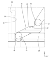
- the left and right side walls 32 of the movable member 30 each include a pair of front and rear entry grooves 41, a pair of front and rear first guide grooves 42, and a pair of front and rear first escape grooves 43. , a pair of front and rear communication grooves 44, a pair of front and rear second guide grooves 45, and a pair of front and rear second escape grooves 46 are formed.
- the first guide groove 42 and the second guide groove 45 have a function of fitting the first housing 12 and the second housing 50 into each other during the process in which the first housing 12 and the second housing 50 are displaced downward.
- the pair of entry grooves 41 are spaced apart in the front-rear direction and are arranged parallel to each other.
- the entry groove 41 extends in the vertical direction parallel to the fitting direction of both the housings 12 and 50, and opens at the upper end surface of the side wall portion 32.
- the pair of first guide grooves 42 are spaced apart in the front-rear direction and are arranged parallel to each other.
- the first guide groove 42 extends obliquely downward from the terminal end (lower end) of the entry groove 41 in a straight line.
- the starting end (upper end) of the first guide groove 42 is the same as the terminal end of the entry groove 41 .
- the pair of first guide grooves 42 are oblique to both the up-down direction (direction parallel to the fitting direction of both housings 12, 50) and the front-back direction (direction perpendicular to the fitting direction of both housings 12, 50). to do.
- the pair of first relief grooves 43 are arranged parallel to each other with an interval in the front-rear direction.
- the first escape groove 43 extends downward from the terminal end (lower rear end) of the first guide groove 42 .
- the starting end (upper end) of the first relief groove 43 is the same as the terminal end of the first guide groove 42 .
- the vertical dimension of the first relief groove 43 is smaller than the vertical dimension of the first guide groove 42 .
- the distance between the pair of entry grooves 41 in the front-rear direction, the distance between the pair of first guide grooves 42 in the front-rear direction, and the distance between the pair of first relief grooves 43 in the front-rear direction are all the same as the distance between the pair of first cam pins 17. It has the same dimensions as .
- the pair of communication grooves 44 are arranged parallel to each other with an interval in the front-rear direction.
- the communication groove 44 extends linearly from the terminal end (lower end) of the first relief groove 43 to the rear (in a direction perpendicular to the fitting direction of both housings 12 and 50).
- the starting end (front end) of the communication groove 44 is the same as the terminal end of the first relief groove 43 .
- a holding protrusion 47 is formed in the rear communication groove 44. As shown in FIG. The holding protrusion 47 projects downward from the upper surface of both the upper and lower surfaces forming the communication groove 44 .
- the pair of second guide grooves 45 are arranged parallel to each other with an interval in the front-rear direction.
- the second guide groove 45 extends linearly from the terminal end (rear end) of the communication groove 44 diagonally downward and rearward.
- the starting end (upper front end) of the second guide groove 45 is the same as the terminal end of the communication groove 44 .
- the pair of second guide grooves 45 are diagonal with respect to both the up-down direction and the front-back direction.
- the length of the second guide groove 45 in the front-rear direction is the same as the length of the first guide groove 42 in the front-rear direction.
- the vertical dimension of the second guide groove 45 is smaller than the vertical dimension of the first guide groove 42 .
- the inclination angle ⁇ of the second guide groove 45 with respect to the horizontal direction (front-back direction) is equal to the inclination angle ⁇ of the first guide groove 42.
- the pair of second relief grooves 46 are arranged parallel to each other with an interval in the front-rear direction.
- the second escape groove 46 extends downward from the terminal end (lower rear end) of the second guide groove 45 .
- the starting end (upper end) of the second relief groove 46 is the same as the terminal end of the second guide groove 45 .
- the vertical dimension of the second relief groove 46 (direction parallel to the fitting direction of both housings 12 and 50) is smaller than the vertical dimension of the second guide groove 45, and the vertical dimension of the first relief groove 43 is smaller than the vertical dimension of the second guide groove 45.
- the dimensions are the same as the dimensions.
- the vertical dimensions of the first relief groove 43 and the second relief groove 46 are set to be larger than the assumed vertical positional deviation amount between the first base member 11 and the second base member 21.
- the second housing 50 is constructed by assembling a plurality of parts, and has a housing main body 51, a front plate part 54, and a rear plate part 55, as shown in FIGS. 4 and 5.
- a plurality of female second terminal fittings (not shown) are housed inside the housing main body 51 .
- An electric wire (not shown) connected to the second terminal fitting is led out below the housing body 51.
- a guide hole 52 extending in the vertical direction is formed on the surface of the housing body 51 facing the first housing 12 .
- a second tapered surface 52S that expands upward is formed at the opening edge of the guide hole 52.
- a pair of second cam pins 53 having a cylindrical protrusion shape are formed on both left and right outer surfaces of the housing body 51, respectively.
- the pair of second cam pins 53 are spaced apart from each other in the front-rear direction and are arranged at the same height in the up-down direction.
- the distance between the pair of second cam pins 53 is the same as the distance between the pair of first cam pins 17, the distance between the pair of second guide grooves 45 in the front-rear direction, and the distance between the pair of second relief grooves 46 in the front-rear direction. .
- the front plate portion 54 has a flat plate shape with the thickness direction facing the front-rear direction.
- the front plate portion 54 is formed to rise upward from the lower end of the front surface of the housing body 51.
- the rear plate portion 55 has a flat plate shape with the thickness direction facing the front-rear direction.
- the rear plate portion 55 is formed to rise upward from the lower end of the rear surface of the housing body 51.
- a connecting groove 56 extending in the left-right direction over the entire width of the front plate part 54 is formed on the rear surface of the front plate part 54 .
- a connecting groove 56 extending in the left-right direction over the entire width of the rear plate part 55 is also formed on the rear surface of the rear plate part 55. As shown in FIG.
- a pair of holding recesses 57 are formed at both left and right ends of the connecting groove 56 formed in the front plate portion 54.
- a guide recess 58 is formed at the upper end of the rear surface of the front plate 54 and is cut out from the upper edge of the front plate 54 toward the connecting groove 56 .
- a guide recess 58 is formed at the upper end of the rear surface of the rear plate part 55, which is cut out from the upper edge of the rear plate part 55 toward the connecting groove 56.
- the assembly process and fitting process of the connector device will be explained.
- the first connector 10 is kept on standby above the second connector 20.
- a second terminal fitting (not shown) is attached to the second housing 50
- the second housing 50 is assembled to the movable member 30, and the movable member 30 is assembled to the second base member 21.
- the second housing 50 is placed above the movable member 30, and the electric wire (not shown) led out below the second housing 50 is connected to the movable member 30. It penetrates into the fitting space 33.
- the second housing 50 is moved downward, and the four second cam pins 53 are individually entered into the four entry grooves 41. Thereafter, while advancing the second housing 50 into the fitting space 33, the four second cam pins 53 are sequentially brought into sliding contact with the first guide groove 42, the first escape groove 43, and the communication groove 44, and as shown in FIG. 7, it is moved to the starting end of the second guide groove 45. During this time, the second housing 50 is displaced diagonally downward and rearward relative to the movable member 30.
- the second housing 50 is held at the starting end of the second guide groove 45 in a state where relative displacement in the front-back direction and the up-down direction with respect to the movable member 30 is restricted. Through the above steps, the assembly of the second housing 50 to the movable member 30 is completed.
- the movable member 30 is assembled to the second base member 21 from the rear. At this time, the lower end portion of the movable member 30 is advanced into the working space 22 while the groove portion 35 is fitted into the guide rail 23 and brought into sliding contact. As shown in FIG. 13, when the locking protrusion 37 of the elastic locking piece 36 is fitted into the fitting start position recess 24, the assembly of the movable member 30 to the second base member 21 is completed. In this state, the movable member 30 is held at the fitting start position by the engagement between the elastic locking piece 36 and the fitting start position recess 24.
- the assembly of the second connector 20 is completed, and at the same time, preparations for the second connector 20 to start fitting with the first connector 10 are completed.
- the movable member 30 can be assembled to the second base member 21 before the second housing 50 is assembled to the movable member 30.
- the first base member 11 is lowered to approach the second base member 21, and the lower end of the guide pin 16 is fitted into the guide hole 52.
- the first housing 12 and the second housing 50 are misaligned in the horizontal direction (front-back direction or left-right direction)
- the first tapered surface 16S and the second tapered surface 52S come into sliding contact
- the second The housing 50 and the movable member 30 are displaced in the front-rear direction or the left-right direction, and the positional deviation between the housings 12 and 50 is absorbed. Since a horizontal clearance is ensured between the movable member 30 and the second base member 21, the second base member 21 does not move.
- the first cam pin 17 moves downward within the first guide groove 42 and presses the inclined surface of the first guide groove 42, so that the movable member 30 , and is guided by the guide rail 23 and pushed forward.
- the inclined surface of the second guide groove 45 presses the second cam pin 53 obliquely downward and forward. Since the second housing 50 is restricted from moving in the front-rear direction by fitting with the first housing 12, the second housing 50 is pushed downward as the movable member 30 moves forward. That is, the first housing 12 and the second housing 50 move downward without relative displacement in the front-back direction.
- the inclination angle ⁇ of the first guide groove 42 with respect to the horizontal direction is set to be larger than the inclination angle ⁇ of the second guide groove 45. Therefore, when the movable member 30 moves forward by a certain distance, the distance that the first housing 12 moves downward (in the direction of approaching the second housing 50 and the movable member 30) is the same as the distance that the second housing 50 moves downward (movable). the distance traveled in the direction toward the member 30). As a result, in the process in which the first connector 10 approaches the second base member 21, the first housing 12 and the second housing 50 move downward while the first housing 12 approaches the second housing 50, and both housings The fitting operation of 12 and 50 proceeds.
- the first cam pin 17 reaches the terminal end of the first guide groove 42 (the starting end of the first relief groove 43),
- the second cam pin 53 reaches the terminal end of the second guide groove 45 (the starting end of the second relief groove 46).
- the movable member 30 reaches the fitting completion position. As shown in FIG. 14, the movable member 30 is held at the fully fitted position by the locking protrusion 37 of the elastic locking piece 36 and the fully fitted position recess 25.
- the positional deviation in the vertical direction (direction parallel to the fitting direction) between the first base member 11 and the second base member 21 is corrected during the fitting process between the first housing 12 and the second housing 50.
- the connector device of the first embodiment after the fitting of both the housings 12 and 50 is completed, by integrally moving both the housings 12 and 50 in the properly fitted state, the first base member 11 and the positional shift of the second base member 21 is absorbed. Therefore, the depth of engagement between both housings 12 and 50 is stabilized.
- the front and rear connecting protrusions 19 of the first housing 12 and the front and rear connecting grooves 56 of the second housing 50 fit together.
- the first connector 10 is moved upward.
- the second housing 50 moves up together with the first housing 12 due to the engagement between the connecting protrusion 19 and the connecting groove 56 .
- the first cam pin 17 moves within the first relief groove 43 and the second cam pin 53 moves within the second relief groove 46.
- the first connector 10 is further raised.
- the first cam pin 17 rises faster than the second cam pin 53 due to the difference in inclination angle between the first guide groove 42 and the second guide groove 45, so that it is connected to the connecting protrusion 19.
- the groove 56 is unlocked.
- the coupling protrusion 19 and the coupling groove 56 are disengaged, the first housing 12 and the second housing 50 are disengaged, so that only the first housing 12 rises and both housings 12 and 50 separate. .
- the connector device of the first embodiment includes a first connector 10 and a second connector 20.
- the first connector 10 includes a first base member 11 and a first housing 12 fixed to the first base member 11.
- the second connector 20 includes a second base member 21 that is relatively accessible to the first base member 11, a second housing 50, and a movable member 30.
- the second housing 50 is movable relative to the second base member 21, and can be fitted into the first housing 12 as the first base member 11 and second base member 21 approach each other. be.
- the movable member 30 is attached to the second base member 21 and is movable between a fitting start position and a fitting completion position.
- the moving direction of the movable member 30 is a direction perpendicular to the fitting direction of the first housing 12 and the second housing 50.
- the movable member 30 is formed with guide portions (a first guide groove 42 and a second guide groove 45) that extend obliquely with respect to the fitting direction of both the housings 12 and 50.
- the first guide groove 42 and the second guide groove 45 move the movable member 30 from the fitting start position to the fitting completion position.
- the housing 12 and the second housing 50 are guided so as to fit into each other.
- the mating completion position the mating of the first housing 12 and the second housing 50 has been completed, and both the housings 12 and 50 in the mated state are integrally connected to the second housing 50. 2. It becomes possible to make a relative displacement with respect to the base member 21 in a direction parallel to the fitting direction.
- the first housing 12 and the second housing 50 are moved by the first guide groove 42 and the second guide groove 45.
- the movable member 30 moves from the fitting start position to the fitting completion position.
- both housings 12 and 50 are displaced relative to the second base member 21 in the vertical direction parallel to the mating direction while maintaining the mating completion state. be able to.
- the housings 12 and 50 are displaced relative to the second base member 21, the first base member 11 and the second base member 21 are displaced relative to each other in a direction parallel to the fitting direction of the housings 12 and 50. Thereby, it is possible to absorb the positional deviation between the first base member 11 and the second base member 21 in the direction parallel to the fitting direction of both the housings 12 and 50.
- the movable member 30 has a guide function for fitting the first housing 12 and the second housing 50, a first positional deviation absorbing function, and a second positional deviation absorbing function.
- the first positional displacement absorption function causes the second housing 50, which is not fitted to the first housing 12, to be displaced relative to the second base member 21 in two-dimensional directions (front-back direction and left-right direction). It is a function.
- the second positional deviation absorption mechanism is a function that allows the housings 12 and 50 in the fitted state to be vertically displaced relative to the second base member 21.
- the movable member 30 has a guide portion for fitting the first housing 12 and the second housing 50 together.
- the guide portion includes a first guide groove 42 on which the first cam pin 17 of the first housing 12 slides during the process of fitting the housings 12 and 50 together.
- a first relief groove 43 is formed in the movable member 30 and communicates with the terminal end of the first guide groove 42 .
- both the housings 12 and 50 are successively moved against the second base member 21. relative displacement in the mating direction.
- the guide portion of the movable member 30 includes a second guide groove 45 on which the second cam pin 53 of the second housing 50 slides during the process of fitting the housings 12 and 50 together.
- a second relief groove 46 is formed in the movable member 30 and communicates with the terminal end of the second guide groove 45 .
- the second cam pin 53 enters the second escape groove 46, thereby being able to move relative to the movable member 30 in a direction parallel to the mating direction. It becomes possible. Since the guide portion extends diagonally with respect to the fitting direction, the second guide groove 45 included in the guide portion also extends diagonally with respect to the fitting direction.
- the fitting of both the housings 12 and 50 is The stroke in the mating direction during the mating process becomes longer. This makes it possible to avoid a sudden increase in the fitting resistance between the housings 12 and 50, resulting in good workability.
- a pair of first guide grooves 42 are provided at intervals in a direction perpendicular to the fitting direction (a direction parallel to the moving direction of the movable member 30).
- the first cam pins 17 are arranged at the same interval as the interval between the pair of first guide grooves 42 in the front-back direction perpendicular to the fitting direction. According to this configuration, by bringing the pair of first cam pins 17 into sliding contact with the pair of first guide grooves 42, it is possible to prevent the first housing 12 from tilting with respect to the movable member 30.
- a pair of second guide grooves 45 are provided at intervals in a direction perpendicular to the fitting direction (a direction parallel to the moving direction of the movable member 30).
- the second cam pins 53 are arranged at the same interval as the interval between the pair of second guide grooves 45 in the front-back direction perpendicular to the fitting direction. According to this configuration, by bringing the pair of second cam pins 53 into sliding contact with the pair of second guide grooves 45, it is possible to prevent the second housing 50 from tilting with respect to the movable member 30.
- the terminal end of the first relief groove 43 and the starting end of the second guide groove 45 communicate with each other via the communication groove 44. According to this configuration, when the second cam pin 53 is assembled into the second guide groove 45, the second cam pin 53 is attached to the second guide groove 45 by the first guide groove 42, the first relief groove 43, and the communication groove 44. can be induced.
- the movable member 30 is provided with a holding portion (elastic holding piece 38 and holding protrusion 47) that holds the second cam pin 53 at the starting end of the second guide groove 45.
- a holding portion elastic holding piece 38 and holding protrusion 47
- the second housing 50 is positioned relative to the movable member 30, so that the first housing 12 and the second The fitting operation of the housing 50 can be started smoothly.
- a holding portion for holding the second cam pin 53 at the starting end of the second guide groove 45 includes an elastic holding piece 38 .
- the elastic holding piece 38 is formed on the movable member 30 and exhibits a holding function by being engaged with the front plate portion 54 of the second housing 50.
- the first housing 12 is provided with a release portion 18 that releases the locking by the elastic holding piece 38 when the two housings 12 and 50 begin to fit together. According to this configuration, when the two housings 12 and 50 start to fit together, the release part 18 releases the holding by the elastic holding piece 38, and the second housing 50 can move relative to the movable member 30. Become. Since no work is required just to release the holding of the elastic holding piece 38, workability is good.
- the guide part includes the first guide groove and the second guide groove, but the guide part is configured to include only the first guide groove, and the second housing is fitted to the movable member. It may be possible to make a relative displacement in a direction perpendicular to the direction.
- a pair of first guide grooves are provided at intervals in a direction perpendicular to the fitting direction (a direction parallel to the moving direction of the movable member), but the number of first guide grooves is 1.
- a pair of second guide grooves are provided at intervals in a direction perpendicular to the fitting direction (a direction parallel to the moving direction of the movable member), but the number of second guide grooves is 1. It can be just one book, or it can be three or more.
- the terminal end of the first relief groove and the starting end of the second guide groove communicate with each other via the communication groove, but the terminal end of the first relief groove and the starting end of the second guide groove communicate with each other via the communication groove. It doesn't have to be connected.
- the elastic holding piece is formed on the movable member, but the elastic holding piece may be formed on the second housing.
- the second base member is fixed and the first base member is brought close to the second base member, but the first base member is fixed and the second base member is brought close to the first base member.
- both the first base member and the second base member may be brought closer to each other.
Landscapes
- Details Of Connecting Devices For Male And Female Coupling (AREA)
Abstract
Description
第1ベース部材と、
前記第1ベース部材に固定された第1ハウジングと、
前記第1ベース部材に対して相対的に接近可能に設けた第2ベース部材と、
前記第2ベース部材に対して相対変位可能であり、前記第1ベース部材と前記第2ベース部材が接近するのに伴って前記第1ハウジングと嵌合することが可能な第2ハウジングと、
前記第2ベース部材に取り付けられ、嵌合開始位置と嵌合完了位置との間で前記第1ハウジングと前記第2ハウジングの嵌合方向と直交する方向へ移動可能な可動部材と、を備え、
前記可動部材には、前記嵌合方向に対して斜め方向に延びるガイド部が形成され、
前記第1ベース部材と前記第2ベース部材が接近する過程では、前記ガイド部が、前記可動部材を前記嵌合開始位置から前記嵌合完了位置へ移動させながら、前記第1ハウジングと前記第2ハウジングを互いに嵌合させるようにガイドし、
前記可動部材が前記嵌合完了位置に到達した状態では、前記第1ハウジングと前記第2ハウジングの嵌合が完了し、嵌合完了状態の前記第1ハウジングと前記第2ハウジングが一体となって前記第2ベース部材に対して前記嵌合方向と平行な方向へ相対変位することが可能となる。
最初に本開示の実施形態を列記して説明する。
本開示のコネクタ装置は、
(1)第1ベース部材と、前記第1ベース部材に固定された第1ハウジングと、前記第1ベース部材に対して相対的に接近可能に設けた第2ベース部材と、前記第2ベース部材に対して相対変位可能であり、前記第1ベース部材と前記第2ベース部材が接近するのに伴って前記第1ハウジングと嵌合することが可能な第2ハウジングと、前記第2ベース部材に取り付けられ、嵌合開始位置と嵌合完了位置との間で前記第1ハウジングと前記第2ハウジングの嵌合方向と直交する方向へ移動可能な可動部材と、を備えている。前記可動部材には、前記嵌合方向に対して斜め方向に延びるガイド部が形成されている。前記第1ベース部材と前記第2ベース部材が接近する過程では、前記ガイド部が、前記可動部材を前記嵌合開始位置から前記嵌合完了位置へ移動させながら、前記第1ハウジングと前記第2ハウジングを互いに嵌合させるようにガイドする。前記可動部材が前記嵌合完了位置に到達した状態では、前記第1ハウジングと前記第2ハウジングの嵌合が完了し、嵌合完了状態の前記第1ハウジングと前記第2ハウジングが一体となって前記第2ベース部材に対して前記嵌合方向と平行な方向へ相対変位することが可能となる。
[実施例1]
本開示を具体化した実施例1のコネクタ装置を、図1~図18を参照して説明する。本発明は、これらの例示に限定されるものではなく、請求の範囲によって示され、請求の範囲と均等の意味および範囲内でのすべての変更が含まれる。本実施例1において、前後の方向については、図1~14,16,18におけるF方向を前方と定義する。左右の方向については、図1~5,13~17におけるR方向を右方と定義する。上下の方向については、図1~12,15~18におけるU方向を上方と定義する。
本実施例1のコネクタ装置は、図1に示すように、第1コネクタ10と、第1コネクタ10の下方に配置された第2コネクタ20とを有する。第1コネクタ10と第2コネクタ20は互いに嵌合が可能である。第1コネクタ10は、上下方向へ平行移動し得るようになっている。第2コネクタ20は、待ち受け状態(移動しないように固定された状態)で設けられている。第1コネクタ10と第2コネクタ20の嵌合方向は、上下方向である。第1コネクタ10は、第1ベース部材11と、第1ベース部材11の下面に固定された第1ハウジング12とを備えている。第1コネクタ10における第2コネクタ20との対向面は、下方に面している。
図1に示す第1ベース部材11は、板厚方向を上下方向に向けた平板形状をなす。第1ベース部材11は、第2ベース部材21に組み付けるための嵌合部(図示省略)や組付部(図示省略)を有している。第1ハウジング12は、直方形状の端子保持部13と、端子保持部13の下面外周縁から下方へ角筒状に突出したフード部14とを有する。端子保持部13には、雄形をなす複数の第1端子金具15が保持されている。第1端子金具15のタブ(下端部)は、端子保持部13から下向きに突出し、フード部14によって包囲されている。
第2ベース部材21は箱形をなす部材である。図2に示すように、第2ベース部材21の内部には、第2ベース部材21の上面と後面とに開放された作動空間22が形成されている。第2ベース部材21の水平な上壁部のうち、作動空間22の開口縁部を構成する部位は、前後方向に延びる左右一対のガイドレール23として機能する。両ガイドレール23には、夫々、嵌合開始位置用凹部24と、嵌合開始位置用凹部24よりも前方に配置された嵌合完了位置用凹部25とが形成されている。
本発明は、上記記述及び図面によって説明した実施例に限定されるものではなく、請求の範囲によって示される。本発明には、請求の範囲と均等の意味及び請求の範囲内でのすべての変更が含まれ、下記の実施形態も含まれる。
上記実施例1では、ガイド部が、第1ガイド溝と第2ガイド溝を含んでいるが、ガイド部を、第1ガイド溝のみを含む構成とし、第2ハウジングが可動部材に対して嵌合方向と直交する方向に相対変位し得るようになっていてもよい。
上記実施例1では、第1ガイド溝が嵌合方向と直交する方向(可動部材の移動方向と平行な方向)に間隔を空けて一対設けられているが、第1ガイド溝の数は、1本だけでもよく、3本以上でもよい。
上記実施例1では、第2ガイド溝が嵌合方向と直交する方向(可動部材の移動方向と平行な方向)に間隔を空けて一対設けられているが、第2ガイド溝の数は、1本だけでもよく、3本以上でもよい。
上記実施例1では、第1逃がし溝の終端部と第2ガイド溝の始端部とが連通溝を介して連通しているが、第1逃がし溝の終端部と第2ガイド溝の始端部は連通していなくてもよい。
上記実施例1では、弾性保持片を可動部材に形成したが、弾性保持片は、第2ハウジングに形成してもよい。
上記実施例1では、第2ベース部材を固定し、第1ベース部材を第2ベース部材に接近させるようにしたが、第1ベース部材を固定し、第2ベース部材を第1ベース部材に接近させるようにしてもよく、第1ベース部材と第2ベース部材の両方を互いに接近させるようにしてもよい。
11…第1ベース部材
12…第1ハウジング
13…端子保持部
14…フード部
15…第1端子金具
16…ガイドピン
16S:第1テーパ面
17…第1カムピン
18…解除部
19…連結突起
20…第2コネクタ
21…第2ベース部材
22…作動空間
23…ガイドレール
24…嵌合開始位置用凹部
25…嵌合完了位置用凹部
30…可動部材
31…後壁部
32…側壁部
33…嵌合空間
34…リブ
35…溝部
36…弾性係止片
37…係止突起
38…弾性保持片(保持部)
39…突起部
41…進入溝
42…第1ガイド溝(ガイド部)
43…第1逃がし溝
44…連通溝
45…第2ガイド溝(ガイド部)
46…第2逃がし溝
47…保持突起(保持部)
50…第2ハウジング
51…ハウジング本体
52…ガイド孔
52S…第2テーパ面
53…第2カムピン
54…前板部
55…後板部
56…連結溝
57…保持凹部
58…ガイド凹部
α…第1ガイド溝の傾斜角度
β…第2ガイド溝の傾斜角度
Claims (8)
- 第1ベース部材と、
前記第1ベース部材に固定された第1ハウジングと、
前記第1ベース部材に対して相対的に接近可能に設けた第2ベース部材と、
前記第2ベース部材に対して相対変位可能であり、前記第1ベース部材と前記第2ベース部材が接近するのに伴って前記第1ハウジングと嵌合することが可能な第2ハウジングと、
前記第2ベース部材に取り付けられ、嵌合開始位置と嵌合完了位置との間で前記第1ハウジングと前記第2ハウジングの嵌合方向と直交する方向へ移動可能な可動部材と、を備え、
前記可動部材には、前記嵌合方向に対して斜め方向に延びるガイド部が形成され、
前記第1ベース部材と前記第2ベース部材が接近する過程では、前記ガイド部が、前記可動部材を前記嵌合開始位置から前記嵌合完了位置へ移動させながら、前記第1ハウジングと前記第2ハウジングを互いに嵌合させるようにガイドし、
前記可動部材が前記嵌合完了位置に到達した状態では、前記第1ハウジングと前記第2ハウジングの嵌合が完了し、嵌合完了状態の前記第1ハウジングと前記第2ハウジングが一体となって前記第2ベース部材に対して前記嵌合方向と平行な方向へ相対変位することが可能となるコネクタ装置。 - 前記ガイド部は、前記第1ハウジングと前記第2ハウジングの嵌合過程で前記第1ハウジングの第1カムピンを摺接させる第1ガイド溝を含み、
前記可動部材には、前記第1ガイド溝の終端部に連通する第1逃がし溝が形成され、
前記可動部材が前記嵌合完了位置に到達したときに、前記第1カムピンは、前記第1逃がし溝に進入することによって、前記可動部材に対し前記嵌合方向と平行な方向へ相対移動することが可能になる請求項1に記載のコネクタ装置。 - 前記ガイド部は、前記第1ハウジングと前記第2ハウジングの嵌合過程で前記第2ハウジングの第2カムピンを摺接させる第2ガイド溝を含み、
前記可動部材には、前記第2ガイド溝の終端部に連通する第2逃がし溝が形成され、
前記可動部材が前記嵌合完了位置に到達したときに、前記第2カムピンは、前記第2逃がし溝に進入することによって、前記可動部材に対し前記嵌合方向と平行な方向へ相対移動することが可能になる請求項2に記載のコネクタ装置。 - 前記第1ガイド溝は、前記嵌合方向と直交する方向に間隔を空けて一対設けられており、
前記第1カムピンは、前記嵌合方向と直交する方向において前記一対の第1ガイド溝の間隔と同じ間隔を空けて配置されている請求項2又は請求項3に記載のコネクタ装置。 - 前記第2ガイド溝は、前記嵌合方向と直交する方向に間隔を空けて一対設けられており、
前記第2カムピンは、前記嵌合方向と直交する方向において前記一対の第2ガイド溝の間隔と同じ間隔を空けて配置されている請求項3に記載のコネクタ装置。 - 前記第1逃がし溝の終端部と前記第2ガイド溝の始端部とが連通している請求項3に記載のコネクタ装置。
- 前記可動部材には、前記第2カムピンを前記第2ガイド溝の始端部に保持する保持部が設けられている請求項3に記載のコネクタ装置。
- 前記保持部は、前記第2ハウジングと前記可動部材のうち一方に形成され、前記第2ハウジングと前記可動部材のうち他方に係止することによって保持機能を発揮する弾性保持片を含んでおり、
前記第1ハウジングには、前記第1ハウジングと前記第2ハウジングとの嵌合を開始したときに、前記弾性保持片による係止を解除する解除部が設けられている請求項7に記載のコネクタ装置。
Priority Applications (2)
| Application Number | Priority Date | Filing Date | Title |
|---|---|---|---|
| CN202380055480.9A CN119585958A (zh) | 2022-07-29 | 2023-07-10 | 连接器装置 |
| US18/995,138 US20260039059A1 (en) | 2022-07-29 | 2023-07-10 | Connector device |
Applications Claiming Priority (2)
| Application Number | Priority Date | Filing Date | Title |
|---|---|---|---|
| JP2022121173A JP7783559B2 (ja) | 2022-07-29 | 2022-07-29 | コネクタ装置 |
| JP2022-121173 | 2022-07-29 |
Publications (1)
| Publication Number | Publication Date |
|---|---|
| WO2024024482A1 true WO2024024482A1 (ja) | 2024-02-01 |
Family
ID=89706251
Family Applications (1)
| Application Number | Title | Priority Date | Filing Date |
|---|---|---|---|
| PCT/JP2023/025478 Ceased WO2024024482A1 (ja) | 2022-07-29 | 2023-07-10 | コネクタ装置 |
Country Status (4)
| Country | Link |
|---|---|
| US (1) | US20260039059A1 (ja) |
| JP (2) | JP7783559B2 (ja) |
| CN (1) | CN119585958A (ja) |
| WO (1) | WO2024024482A1 (ja) |
Citations (6)
| Publication number | Priority date | Publication date | Assignee | Title |
|---|---|---|---|---|
| JP2000036357A (ja) * | 1998-07-16 | 2000-02-02 | Tokai Rika Co Ltd | プラグイン結合構造 |
| JP2000123916A (ja) * | 1998-10-16 | 2000-04-28 | Fujikura Ltd | 補機用コネクタ |
| JP2004111318A (ja) * | 2002-09-20 | 2004-04-08 | Sumitomo Wiring Syst Ltd | コネクタ |
| JP2004111265A (ja) * | 2002-09-19 | 2004-04-08 | Sumitomo Wiring Syst Ltd | コネクタ |
| JP2004119135A (ja) * | 2002-09-25 | 2004-04-15 | Sumitomo Wiring Syst Ltd | コネクタの取付け構造 |
| JP2004214105A (ja) * | 2003-01-07 | 2004-07-29 | Sumitomo Wiring Syst Ltd | コネクタの接続構造 |
-
2022
- 2022-07-29 JP JP2022121173A patent/JP7783559B2/ja active Active
-
2023
- 2023-07-10 WO PCT/JP2023/025478 patent/WO2024024482A1/ja not_active Ceased
- 2023-07-10 US US18/995,138 patent/US20260039059A1/en active Pending
- 2023-07-10 CN CN202380055480.9A patent/CN119585958A/zh active Pending
-
2025
- 2025-11-27 JP JP2025206886A patent/JP2026020346A/ja active Pending
Patent Citations (6)
| Publication number | Priority date | Publication date | Assignee | Title |
|---|---|---|---|---|
| JP2000036357A (ja) * | 1998-07-16 | 2000-02-02 | Tokai Rika Co Ltd | プラグイン結合構造 |
| JP2000123916A (ja) * | 1998-10-16 | 2000-04-28 | Fujikura Ltd | 補機用コネクタ |
| JP2004111265A (ja) * | 2002-09-19 | 2004-04-08 | Sumitomo Wiring Syst Ltd | コネクタ |
| JP2004111318A (ja) * | 2002-09-20 | 2004-04-08 | Sumitomo Wiring Syst Ltd | コネクタ |
| JP2004119135A (ja) * | 2002-09-25 | 2004-04-15 | Sumitomo Wiring Syst Ltd | コネクタの取付け構造 |
| JP2004214105A (ja) * | 2003-01-07 | 2004-07-29 | Sumitomo Wiring Syst Ltd | コネクタの接続構造 |
Also Published As
| Publication number | Publication date |
|---|---|
| JP2026020346A (ja) | 2026-02-06 |
| CN119585958A (zh) | 2025-03-07 |
| JP7783559B2 (ja) | 2025-12-10 |
| JP2024018083A (ja) | 2024-02-08 |
| US20260039059A1 (en) | 2026-02-05 |
Similar Documents
| Publication | Publication Date | Title |
|---|---|---|
| JP5846105B2 (ja) | レバー式コネクタ | |
| KR20110066103A (ko) | 레버 커넥터 | |
| JP7480905B2 (ja) | コネクタ | |
| JP4950797B2 (ja) | 可動ガイド部材付きコネクタ | |
| JP3804830B2 (ja) | コネクタ | |
| WO2021192928A1 (ja) | カードエッジコネクタ及び回路基板 | |
| WO2024024482A1 (ja) | コネクタ装置 | |
| JP7447777B2 (ja) | コネクタ | |
| US11799238B2 (en) | Connector | |
| WO2018131447A1 (ja) | コネクタ | |
| JP2004214105A (ja) | コネクタの接続構造 | |
| US20250210915A1 (en) | Connector | |
| JP2002124341A (ja) | コネクタ | |
| JP3969266B2 (ja) | コネクタの取付け構造 | |
| JP2005347082A (ja) | コネクタ | |
| JP7850373B2 (ja) | コネクタ | |
| JP7413931B2 (ja) | コネクタ | |
| JP2024162010A (ja) | コネクタ | |
| JP2025147850A (ja) | コネクタ | |
| JP2026057983A (ja) | コネクタ | |
| JP2024067655A (ja) | コネクタ | |
| WO2021005992A1 (ja) | コネクタ | |
| JP3266024B2 (ja) | コネクタ | |
| WO2025052777A1 (ja) | コネクタ装置 | |
| JP2024134107A (ja) | コネクタ、コネクタ製造装置、及びコネクタ製造方法 |
Legal Events
| Date | Code | Title | Description |
|---|---|---|---|
| 121 | Ep: the epo has been informed by wipo that ep was designated in this application |
Ref document number: 23846213 Country of ref document: EP Kind code of ref document: A1 |
|
| WWE | Wipo information: entry into national phase |
Ref document number: 18995138 Country of ref document: US |
|
| WWE | Wipo information: entry into national phase |
Ref document number: 202380055480.9 Country of ref document: CN |
|
| NENP | Non-entry into the national phase |
Ref country code: DE |
|
| WWP | Wipo information: published in national office |
Ref document number: 202380055480.9 Country of ref document: CN |
|
| 122 | Ep: pct application non-entry in european phase |
Ref document number: 23846213 Country of ref document: EP Kind code of ref document: A1 |
|
| WWP | Wipo information: published in national office |
Ref document number: 18995138 Country of ref document: US |