WO2024024401A1 - 鋼線、及び鋼線の製造方法 - Google Patents
鋼線、及び鋼線の製造方法 Download PDFInfo
- Publication number
- WO2024024401A1 WO2024024401A1 PCT/JP2023/024538 JP2023024538W WO2024024401A1 WO 2024024401 A1 WO2024024401 A1 WO 2024024401A1 JP 2023024538 W JP2023024538 W JP 2023024538W WO 2024024401 A1 WO2024024401 A1 WO 2024024401A1
- Authority
- WO
- WIPO (PCT)
- Prior art keywords
- steel wire
- less
- mass
- wire
- steel
- Prior art date
- Legal status (The legal status is an assumption and is not a legal conclusion. Google has not performed a legal analysis and makes no representation as to the accuracy of the status listed.)
- Ceased
Links
Images

Classifications
-
- C—CHEMISTRY; METALLURGY
- C22—METALLURGY; FERROUS OR NON-FERROUS ALLOYS; TREATMENT OF ALLOYS OR NON-FERROUS METALS
- C22C—ALLOYS
- C22C38/00—Ferrous alloys, e.g. steel alloys
- C22C38/18—Ferrous alloys, e.g. steel alloys containing chromium
-
- C—CHEMISTRY; METALLURGY
- C21—METALLURGY OF IRON
- C21D—MODIFYING THE PHYSICAL STRUCTURE OF FERROUS METALS; GENERAL DEVICES FOR HEAT TREATMENT OF FERROUS OR NON-FERROUS METALS OR ALLOYS; MAKING METAL MALLEABLE, e.g. BY DECARBURISATION OR TEMPERING
- C21D8/00—Modifying the physical properties of ferrous metals or ferrous alloys by deformation combined with, or followed by, heat treatment
- C21D8/06—Modifying the physical properties of ferrous metals or ferrous alloys by deformation combined with, or followed by, heat treatment during manufacturing of rods or wires
-
- B—PERFORMING OPERATIONS; TRANSPORTING
- B21—MECHANICAL METAL-WORKING WITHOUT ESSENTIALLY REMOVING MATERIAL; PUNCHING METAL
- B21C—MANUFACTURE OF METAL SHEETS, WIRE, RODS, TUBES, PROFILES OR LIKE SEMI-MANUFACTURED PRODUCTS OTHERWISE THAN BY ROLLING; AUXILIARY OPERATIONS USED IN CONNECTION WITH METAL-WORKING WITHOUT ESSENTIALLY REMOVING MATERIAL
- B21C1/00—Manufacture of metal sheets, wire, rods, tubes or like semi-manufactured products by drawing
- B21C1/02—Drawing metal wire or like flexible metallic material by drawing machines or apparatus in which the drawing action is effected by drums
-
- C—CHEMISTRY; METALLURGY
- C21—METALLURGY OF IRON
- C21D—MODIFYING THE PHYSICAL STRUCTURE OF FERROUS METALS; GENERAL DEVICES FOR HEAT TREATMENT OF FERROUS OR NON-FERROUS METALS OR ALLOYS; MAKING METAL MALLEABLE, e.g. BY DECARBURISATION OR TEMPERING
- C21D1/00—General methods or devices for heat treatment, e.g. annealing, hardening, quenching or tempering
- C21D1/26—Methods of annealing
- C21D1/32—Soft annealing, e.g. spheroidising
-
- C—CHEMISTRY; METALLURGY
- C21—METALLURGY OF IRON
- C21D—MODIFYING THE PHYSICAL STRUCTURE OF FERROUS METALS; GENERAL DEVICES FOR HEAT TREATMENT OF FERROUS OR NON-FERROUS METALS OR ALLOYS; MAKING METAL MALLEABLE, e.g. BY DECARBURISATION OR TEMPERING
- C21D7/00—Modifying the physical properties of iron or steel by deformation
- C21D7/02—Modifying the physical properties of iron or steel by deformation by cold working
- C21D7/10—Modifying the physical properties of iron or steel by deformation by cold working of the whole cross-section, e.g. of concrete reinforcing bars
-
- C—CHEMISTRY; METALLURGY
- C21—METALLURGY OF IRON
- C21D—MODIFYING THE PHYSICAL STRUCTURE OF FERROUS METALS; GENERAL DEVICES FOR HEAT TREATMENT OF FERROUS OR NON-FERROUS METALS OR ALLOYS; MAKING METAL MALLEABLE, e.g. BY DECARBURISATION OR TEMPERING
- C21D9/00—Heat treatment, e.g. annealing, hardening, quenching or tempering, adapted for particular articles; Furnaces therefor
- C21D9/52—Heat treatment, e.g. annealing, hardening, quenching or tempering, adapted for particular articles; Furnaces therefor for wires; for strips ; for rods of unlimited length
- C21D9/525—Heat treatment, e.g. annealing, hardening, quenching or tempering, adapted for particular articles; Furnaces therefor for wires; for strips ; for rods of unlimited length for wire, for rods
-
- C—CHEMISTRY; METALLURGY
- C21—METALLURGY OF IRON
- C21D—MODIFYING THE PHYSICAL STRUCTURE OF FERROUS METALS; GENERAL DEVICES FOR HEAT TREATMENT OF FERROUS OR NON-FERROUS METALS OR ALLOYS; MAKING METAL MALLEABLE, e.g. BY DECARBURISATION OR TEMPERING
- C21D9/00—Heat treatment, e.g. annealing, hardening, quenching or tempering, adapted for particular articles; Furnaces therefor
- C21D9/52—Heat treatment, e.g. annealing, hardening, quenching or tempering, adapted for particular articles; Furnaces therefor for wires; for strips ; for rods of unlimited length
- C21D9/54—Furnaces for treating strips or wire
- C21D9/64—Patenting furnaces
-
- C—CHEMISTRY; METALLURGY
- C22—METALLURGY; FERROUS OR NON-FERROUS ALLOYS; TREATMENT OF ALLOYS OR NON-FERROUS METALS
- C22C—ALLOYS
- C22C38/00—Ferrous alloys, e.g. steel alloys
- C22C38/02—Ferrous alloys, e.g. steel alloys containing silicon
-
- C—CHEMISTRY; METALLURGY
- C22—METALLURGY; FERROUS OR NON-FERROUS ALLOYS; TREATMENT OF ALLOYS OR NON-FERROUS METALS
- C22C—ALLOYS
- C22C38/00—Ferrous alloys, e.g. steel alloys
- C22C38/04—Ferrous alloys, e.g. steel alloys containing manganese
-
- C—CHEMISTRY; METALLURGY
- C21—METALLURGY OF IRON
- C21D—MODIFYING THE PHYSICAL STRUCTURE OF FERROUS METALS; GENERAL DEVICES FOR HEAT TREATMENT OF FERROUS OR NON-FERROUS METALS OR ALLOYS; MAKING METAL MALLEABLE, e.g. BY DECARBURISATION OR TEMPERING
- C21D2201/00—Treatment for obtaining particular effects
- C21D2201/05—Grain orientation
-
- C—CHEMISTRY; METALLURGY
- C21—METALLURGY OF IRON
- C21D—MODIFYING THE PHYSICAL STRUCTURE OF FERROUS METALS; GENERAL DEVICES FOR HEAT TREATMENT OF FERROUS OR NON-FERROUS METALS OR ALLOYS; MAKING METAL MALLEABLE, e.g. BY DECARBURISATION OR TEMPERING
- C21D2211/00—Microstructure comprising significant phases
- C21D2211/009—Pearlite
Definitions
- the present disclosure relates to a steel wire and a method for manufacturing the steel wire.
- This application claims priority based on Japanese Application No. 2022-121882 filed on July 29, 2022, and incorporates all the contents described in the said Japanese application.
- Patent Document 1 discloses a steel wire with a wire diameter of 0.05 mm or more and 0.38 mm or less and a tensile strength of 3300 MPa or more and 3900 MPa or less. Such steel wires are used, for example, as reinforcing materials for tires.
- the method for manufacturing a steel wire described in Patent Document 1 is as follows. Obtain the steel wire material. Steel wire rods are heated through hot rolling to become austenite, and then cooled to become pearlite. The pearlitized steel wire rod is further processed into a predetermined wire diameter by being subjected to a combination of wire drawing and patenting treatment. A final patenting process is performed on the steel wire rod having a predetermined wire diameter. Next, the steel wire rod is subjected to a first wire drawing process.
- the wire drawn material obtained by the first wire drawing process is subjected to a swaging process.
- the intermediate wire drawing material obtained by the swaging process is subjected to a second wire drawing process.
- a steel wire is obtained by such a manufacturing method.
- the steel wire of the present disclosure is 0.9% by mass or more and 1.1% by mass or less of carbon, 0.15% by mass or more and 0.25% by mass or less of silicon, 0.25% by mass or more and 0.35% by mass or less of manganese; 0.15% by mass or more and 0.25% by mass or less of chromium, The remainder consists of iron and steel, which is an unavoidable impurity.
- the steel has a pearlite structure
- the diameter of the steel wire is 0.05 mm or more and 0.45 mm or less
- the tensile strength of the steel wire is 3900 MPa or more and 4700 MPa or less
- the structure of the surface area from the surface of the steel wire to a depth of 10% of the diameter is as follows: A tissue in which the total proportion A of the proportion A 100 of the texture in the ⁇ 100> direction, the proportion A 110 of the texture in the ⁇ 110> direction, and the proportion A 111 of the texture in the ⁇ 111> direction is 32% or less.
- the ratio A 100 is the area ratio of crystal grains whose ⁇ 100> orientation has a predetermined orientation among all crystal grains in the observation field of the surface region
- the ratio A 110 is the area ratio of crystal grains whose ⁇ 110> orientation has a predetermined orientation among all crystal grains in the observation field of the surface region
- the ratio A 111 is the area ratio of crystal grains having a predetermined ⁇ 111> orientation among all crystal grains in the observation field of the surface region.
- FIG. 1 is a sectional view showing a longitudinal section of a steel wire according to an embodiment.
- the steel wire according to the embodiment of the present disclosure is 0.9% by mass or more and 1.1% by mass or less of carbon, 0.15% by mass or more and 0.25% by mass or less of silicon, 0.25% by mass or more and 0.35% by mass or less of manganese; 0.15% by mass or more and 0.25% by mass or less of chromium, The remainder consists of iron and steel, which is an unavoidable impurity.
- the steel has a pearlite structure
- the diameter of the steel wire is 0.05 mm or more and 0.45 mm or less
- the tensile strength of the steel wire is 3900 MPa or more and 4700 MPa or less
- the structure of the surface area from the surface of the steel wire to a depth of 10% of the diameter is as follows: A tissue in which the total proportion A of the proportion A 100 of the texture in the ⁇ 100> direction, the proportion A 110 of the texture in the ⁇ 110> direction, and the proportion A 111 of the texture in the ⁇ 111> direction is 32% or less.
- the ratio A 100 is the area ratio of crystal grains whose ⁇ 100> orientation has a predetermined orientation among all crystal grains in the observation field of the surface region
- the ratio A 110 is the area ratio of crystal grains whose ⁇ 110> orientation has a predetermined orientation among all crystal grains in the observation field of the surface region
- the ratio A 111 is the area ratio of crystal grains having a predetermined ⁇ 111> orientation among all crystal grains in the observation field of the surface region.
- the total proportion A of each of the above-mentioned textures is 32% or less, so that the surface region has few crystal grains oriented in a specific direction. In other words, the structure of the surface region has a randomly distributed crystal orientation.
- Such a steel wire is susceptible to deformation in its surface area when subjected to bending and twisting.
- a steel wire in which the total proportion A is 32% or less has excellent toughness.
- the steel wire of the present disclosure has a tensile strength of 3900 MPa or more, so it has high strength. Therefore, the steel wire of the present disclosure has both high strength and toughness.
- the steel wire of the present disclosure has a diameter of 0.05 mm or more and 0.45 mm or less, it is possible to achieve weight reduction while ensuring the necessary strength.
- the total integration degree B of the integration degree B 100 of the ⁇ 100 ⁇ plane and the accumulation degree B 111 of the ⁇ 111 ⁇ plane may be 8.00 or more and 9.70 or less.
- a steel wire with a total integration degree B of 8.00 or more and 9.70 or less has both high strength and toughness.
- the total integration degree B is the sum of the integration degree B 100 and the integration degree B 111 .
- the total percentage A may be 29% or less.
- the total integration degree B may be 8.40 or more and 9.00 or less.
- the steel wire according to any of the above (1) to (4) is The diameter of the steel wire may be 0.15 mm or more and 0.42 mm or less.
- the steel wire in (5) above is The diameter of the steel wire may be 0.18 mm or more and 0.30 mm or less.
- the steel wire according to any of the above (1) to (6) is The tensile strength of the steel wire may be 3960 MPa or more and 4500 MPa or less.
- the strength is higher.
- the method for manufacturing a steel wire according to the embodiment of the present disclosure includes: 0.9% by mass to 1.1% by mass of carbon; 0.15% by mass to 0.25% by mass of silicon; 0.25% by mass to 0.35% by mass of manganese; A step of preparing a material made of steel containing 15% by mass or more and 0.25% by mass or less of chromium, the balance being iron and unavoidable impurities; a step of performing a first wire drawing process on the material; performing a patenting process on the first wire material that has been subjected to the first wire drawing process; a step of performing a second wire drawing process on the first wire material subjected to the patenting treatment; and a step of performing a skin pass on the second wire rod that has been subjected to the second wire drawing process.
- the method for manufacturing a steel wire of the present disclosure can control the orientation of crystal grains in the surface region of the steel wire by performing a skin pass after wire drawing. Specifically, due to the skin pass, the crystal orientation of the surface region becomes randomly oriented, and the proportion of texture in the surface region becomes small. As a result, a steel wire having both high strength and toughness is obtained.
- the skin pass may be performed on the second wire one or more times and eight times or less.
- the proportion of texture in the surface region can be sufficiently reduced.
- the area reduction rate per skin pass may be 1.0% or more and 6.0% or less.
- the proportion of texture in the surface region can be sufficiently reduced.
- the surface region has a specific structure in a longitudinal section.
- a steel wire 1 will be explained using a three-dimensional orthogonal coordinate system.
- the longitudinal section of the steel wire 1 is parallel to the Y-axis and passes through the center of the steel wire 1.
- the surface area 10 is an area from the surface of the steel wire 1 to a depth of 10% of the diameter of the steel wire 1. The depth is the distance from the surface of the steel wire 1 toward the center.
- the surface region 10 has a specific structure, so that the surface region 10 has fewer crystal grains oriented in a specific direction. In other words, the structure of the surface region 10 has a randomly distributed crystal orientation.
- the steel wire 1 of this embodiment has high strength and improved torsional properties.
- the Y axis is parallel to the longitudinal axis of the steel wire 1.
- the X-axis and Z-axis are each orthogonal to the Y-axis.
- the steel wire 1 contains carbon (C) of 0.9% by mass to 1.1% by mass, silicon (Si) of 0.15% to 0.25% by mass, and 0.25% by mass to 0. It contains manganese (Mn) of .35% by mass or less and chromium (Cr) of 0.15% by mass or more and 0.25% by mass or less, and the remainder is iron (Fe) and steel which is an unavoidable impurity.
- the steel wire 1 contains 0.9% by mass or more and 1.1% by mass or less of C.
- C is an element that increases the strength of the steel wire 1.
- the higher the content of C the higher the strength of the steel wire 1.
- the content of C may be, for example, 1.00% by mass or more and 1.05% by mass or less.
- the composition of the steel wire 1 includes 0.15% by mass or more and 0.25% by mass or less of Si.
- Si is an element effective in deoxidizing steel. Further, Si is dissolved in the ferrite of the pearlite structure and has the effect of increasing the strength of the steel wire 1. If Si is included excessively, the toughness of the steel wire 1 will decrease.
- the content of Si may be, for example, 0.20 mass% or more and 0.25 mass% or less, or 0.20 mass% or more and 0.23 mass% or less.
- the composition of the steel wire 1 includes 0.25% by mass or more and 0.35% by mass or less of Mn.
- Mn is an effective element for deoxidizing steel. Moreover, Mn has the effect of improving the hardenability of steel and increasing the strength of the steel wire 1. If Mn is included excessively, the toughness of the steel wire 1 will decrease.
- the content of Mn may be, for example, 0.27% by mass or more and 0.33% by mass or less, or 0.30% by mass.
- the composition of the steel wire 1 includes 0.15% by mass or more and 0.25% by mass or less of Cr.
- Cr has the effect of increasing the strength of the steel wire 1 by making the lamella spacing of the pearlite structure finer. When Cr is included excessively, pearlite transformation becomes difficult to occur.
- the content of Cr may be, for example, 0.20% by mass or more and 0.25% by mass or less, or 0.20% by mass or more and 0.21% by mass or less.
- the composition of the steel wire 1 may contain unavoidable impurities.
- Unavoidable impurities are, for example, phosphorus (P), sulfur (S), and copper (Cu).
- the content of each of P and S is preferably 0.025% by mass or less.
- the composition of the steel wire 1 can be determined by, for example, ICP optical emission spectrometry.
- the shape of the steel wire 1 can be selected as appropriate.
- the steel wire 1 of this embodiment is a round wire with a circular cross section.
- the cross section of the steel wire 1 is a cross section perpendicular to the Y axis.
- the cross-sectional shape of the steel wire 1 may be non-circular.
- the non-circular shape is, for example, a polygon or an ellipse.
- the polygon is, for example, a rectangle or a hexagon. Rectangles also include squares.
- the diameter of the steel wire 1 is 0.05 mm or more and 0.45 mm or less.
- the diameter of the steel wire 1 is the diameter of a circle having an area equal to the area of the cross section of the steel wire 1.
- the steel wire 1 having such a diameter can be suitably used as a reinforcing material for tires and the like.
- the diameter of the steel wire 1 may be 0.15 mm or more and 0.42 mm or less, or 0.18 mm or more and 0.30 mm or less.
- the tensile strength of the steel wire 1 is 3900 MPa or more and 4700 MPa or less.
- the steel wire 1 having such tensile strength has high strength and can be suitably used as a reinforcing material for tires and the like.
- the tensile strength of the steel wire 1 is the maximum stress until the steel wire 1 breaks when the steel wire 1 is pulled at a constant speed using a tensile testing machine. For example, a 200 mm test piece taken out from the steel wire 1 may be pulled at a tensile speed of 100 mm/min, and the tensile strength until the test piece breaks is measured.
- the tensile strength of the steel wire 1 may be 3900 MPa or more and 4400 MPa or less.
- the structure of the steel wire 1 is mainly pearlite structure.
- the steel wire 1 has the above-mentioned composition and is made of steel having a pearlite structure, so that it can have both high strength and toughness.
- steel wire is manufactured by wire drawing.
- the texture of a drawn steel wire is a texture in which crystal grains extend in the drawing direction and the crystal grains are strongly oriented in the length direction of the steel wire.
- a steel wire having such a texture is difficult to deform when it is bent or twisted, for example. For example, when a steel wire is twisted, it cannot follow the twisting deformation, and the steel wire tends to break or delamination occurs.
- the steel wire 1 of this embodiment has a texture in which a specific crystal plane is oriented in a specific direction in a small proportion in the surface region 10, and the crystal orientation is randomly oriented.
- the surface area 10 is an area from the surface of the steel wire 1 to a depth of 10% of the diameter of the steel wire 1.
- the surface region 10 may be a region having a depth of 5 ⁇ m or more and 20 ⁇ m or less from the surface of the steel wire 1.
- the texture of the surface region 10 has, in the longitudinal section, a proportion A 100 of the texture in the ⁇ 100> direction, a proportion A 110 of the texture in the ⁇ 110> direction, and a proportion A 111 of the texture in the ⁇ 111> direction.
- the total percentage A is 32% or less.
- the proportion of the structure of the surface region 10 excluding the above-mentioned textures is 68% or more.
- ⁇ 100> orientations of crystal grains have a predetermined orientation.
- the ratio A 100 is the area ratio of crystal grains having a predetermined ⁇ 100> orientation among all crystal grains in the observation field 30 of the surface region 10.
- ⁇ 110> orientations of crystal grains have a predetermined orientation.
- the ratio A 110 is the area ratio of crystal grains having a predetermined ⁇ 110> orientation among all crystal grains in the observation field 30 of the surface region 10.
- ⁇ 111> orientations of crystal grains have a predetermined orientation.
- the ratio A 111 is the area ratio of crystal grains having a predetermined ⁇ 111> orientation among all crystal grains in the observation field 30 of the surface region 10.
- the crystal grains in which the ⁇ 100> orientation has a predetermined orientation are crystal grains in which the ⁇ 100> orientation is within 10° with respect to each of the X axis and the Z axis in the longitudinal section.
- a crystal grain whose ⁇ 110> orientation has a predetermined orientation is a crystal grain whose ⁇ 110> orientation is within 10 degrees with respect to each of the X axis and the Z axis.
- a crystal grain whose ⁇ 111> orientation has a predetermined orientation is a crystal grain whose ⁇ 111> orientation is within 10 degrees with respect to each of the X axis and the Z axis.
- Steel wire 1 in which the total proportion A is 32% or less has excellent torsional properties. When the total proportion A is further 31% or less, 30% or less, or 29% or less, the torsional properties are further improved.
- the lower limit of the total percentage A is, for example, 20%.
- the total proportion A is, for example, 20% or more and 32% or less, further 20% or more and 31% or less, 20% or more and 30% or less, and 20% or more and 29% or less.
- Each of the proportion A 100 , the proportion A 110 , and the proportion A 111 is, for example, 4% or more and 20% or less, and further 5% or more and 18% or less.
- the respective ratios of the above-mentioned textures can be determined by electron beam backscatter diffraction (EBSD). Specifically, each ratio is determined by observing the surface region 10 in the longitudinal section of the steel wire 1 shown in FIG. Find it with For example, the ratio A 100 is determined as follows. The orientations of all crystal grains included in the observation field 30 of the surface region 10 are determined. The orientation of crystal grains is the orientation with respect to each direction of the X axis and the Z axis. Among all crystal grains, the area ratio of crystal grains whose ⁇ 100> orientation is within 10 degrees with respect to each of the X axis and the Z axis is determined.
- EBSD electron beam backscatter diffraction
- the average value of the area ratio of crystal grains whose ⁇ 100> orientation is within 10° with respect to the X axis and the area ratio of crystal grains whose ⁇ 100> orientation is within 10° with respect to the Z axis is calculated as ratio A. Set it to 100 .
- the proportion A 110 and the proportion A 111 can also be determined in the same manner as the proportion A 100 .
- the area ratio of crystal grains that are within 10 degrees of each of the ⁇ 111> orientation, ⁇ 110> orientation, and ⁇ 100> orientation is It only needs to be 32% or less of the area.
- the observation field 30 can be selected at any position within the surface area 10.
- the size of the observation field 30 is, for example, a length along the Y axis of 50 ⁇ m or more and 150 ⁇ m or less, and a length along the X axis of 5 ⁇ m or more and 30 ⁇ m or less.
- the length along the Y axis may be 100 ⁇ m, and the length along the X axis may be 20 ⁇ m.
- the observation magnification may be appropriately selected depending on the size of the crystal grains.
- the observation magnification may be, for example, 9000 times or more.
- the observation field 30 may be constructed by connecting a plurality of observation fields.
- the longitudinal section of the steel wire 1 is preferably polished.
- the longitudinal section may be processed, for example, by a cross-section polisher.
- the total integration degree B of the ⁇ 100 ⁇ plane integration degree B 100 and the ⁇ 111 ⁇ plane integration degree B 111 may be, for example, 8.00 or more and 9.70 or less.
- the total integration degree B may be 8.10 or more and 9.60 or less, or 8.40 or more and 9.00 or less.
- the degree of integration B 100 and the degree of integration B 111 are each, for example, 4.00 or more and 5.50 or less.
- the degree of integration B 100 and the degree of integration B 111 are determined from the pole figures of the ⁇ 100 ⁇ plane and the ⁇ 111 ⁇ plane.
- a pole figure is a stereoscopic projection of the crystal orientation distribution of a corresponding crystal plane.
- the distribution of crystal orientation is expressed as the ratio of the number of crystal grains in the crystal orientation of the corresponding crystal plane in the observation field to the number of crystal grains in a sample in which the crystal orientations are randomly distributed.
- the pole figure is an index indicating the degree of accumulation of crystal orientations relative to a random structure.
- a degree of integration of 1 means the same as a random organization. When the degree of integration is greater than 1, it means that there are more crystals oriented in that crystal orientation than in a random structure.
- the degree of agglomeration is represented by contour lines based on the distribution of the degree of agglomeration determined from the pole figure, a plurality of local maximum points with different heights appear in the pole figure.
- the above sample does not have a specific orientation.
- the above sample is obtained, for example, by heat-treating a steel wire at a high temperature.
- the ratio of crystal grains in ⁇ 100>, ⁇ 110>, and ⁇ 111> orientations to an ideal randomly oriented sample can be determined by calculation. The ratio to this calculated value becomes the degree of integration of the pole figures.
- the degree of integration B 100 and the degree of integration B 111 are defined as follows.
- the integration degree B 100 is the largest local maximum point in the pole figure of the ⁇ 100 ⁇ plane.
- the integration degree B 111 is the largest local maximum point in the pole figure of the ⁇ 111 ⁇ plane.
- the steel wire 1 of this embodiment can be suitably used as a reinforcing material embedded in rubber products such as tires.
- rubber products other than tires include conveyor belts, escalator handrails, and hoses. Since the steel wire 1 of this embodiment has high tensile strength, it can ensure strength even if it is thin, so that the weight of the rubber product can be reduced. Since the steel wire 1 of this embodiment has high torsional properties, the steel wire 1 is less likely to break when twisted, and delamination is less likely to occur in the steel wire 1. Further, even if twisting occurs in the steel wire 1 during use of the rubber product, the steel wire 1 is less likely to break and delamination is less likely to occur in the steel wire 1.
- the steel wire 1 of the embodiment can be manufactured by the method of manufacturing a steel wire according to the embodiment.
- the steel wire manufacturing method of the embodiment includes a first step, a second step, a third step, a fourth step, and a fifth step. Each step will be explained in detail below.
- the first step is to prepare a material made of steel.
- the composition of the steel is 0.9% by mass or more and 1.1% by mass of carbon, 0.15% by mass or more and 0.25% by mass of silicon, and 0.25% by mass or more and 0.35% by mass or less. It contains manganese and 0.15% by mass or more and 0.25% by mass or less of chromium, with the balance being iron and inevitable impurities.
- the composition of the strand is the same as that of the steel wire to be manufactured.
- the material is manufactured by a method such as a continuous casting method or a continuous casting and rolling method.
- the material may be processed to have a predetermined diameter, for example by hot rolling.
- the diameter of the material is, for example, 4 mm or more and 6 mm or less.
- the shape of the material is, for example, a round wire with a circular cross section.
- the second step is a step of subjecting the material to a first wire drawing process.
- the first wire drawing process is performed once or multiple times using a die until the diameter of the material reaches a predetermined diameter.
- the first wire drawing process is performed, for example, by a wet process.
- the area reduction rate per first wire drawing process is, for example, 10% or more and 20% or less.
- the area reduction rate per pass is the difference between the cross-sectional area of the material before passing through the die and the cross-sectional area of the material after passing through the die, when the material passes through one die. It is the ratio divided by the cross-sectional area of the previous material.
- a first wire rod subjected to the first wire drawing process is obtained.
- the diameter of the first wire is, for example, 1 mm or more and 2.5 mm or less.
- the total area reduction rate of the first wire drawing process is, for example, 70% or more and 90% or less.
- the total area reduction rate of the first wire drawing process is the difference between the cross-sectional area of the material before the first wire drawing process and the cross-sectional area of the first wire material after the first wire drawing process, divided by the cross-sectional area of the material. It is a percentage.
- the third step is a step of subjecting the first wire material that has been subjected to the first wire drawing process to a patenting process.
- the patenting treatment is a heat treatment for forming the steel constituting the first wire into a pearlite structure.
- the first wire is heated to make the steel an austenite structure, and then the first wire is cooled to make the steel a pearlite structure.
- the first wire is heated to an austenitizing temperature range and held for a certain period of time to austenitize the steel.
- the austenitizing temperature range is a temperature range above the austenitizing temperature, that is, a temperature range above the Acm point.
- the austenitizing temperature range is, for example, 950°C or more and 1000°C or less.
- the holding time in the austenitizing temperature range is, for example, 5 seconds or more and 10 seconds or less.
- the austenitized first wire rod is rapidly cooled to a pearlite transformation temperature range and held for a certain period of time to transform the steel into pearlite.
- the pearlite transformation temperature range is a temperature range lower than the austenitization temperature and higher than the temperature at which martensitic transformation starts, that is, a temperature range above the Ms point.
- the pearlite transformation temperature range is, for example, 500°C or higher and 600°C or lower.
- the holding time in the pearlite transformation temperature range is, for example, 3 seconds or more and 10 seconds or less.
- Such patenting treatment turns the steel into a fine pearlite structure.
- the first wire material is maintained in the pearlite transformation temperature range and then cooled to room temperature.
- the first wire may be heated in an inert gas atmosphere in order to suppress the occurrence of decarburization.
- the fourth step is a step of performing a second wire drawing process on the first wire material that has been subjected to the patenting treatment.
- the second wire drawing process is performed once or multiple times using a die until the diameter of the first wire rod becomes close to the diameter of the steel wire to be manufactured.
- the conditions for the second wire drawing process are the same as those for the first wire drawing process.
- a second wire rod subjected to the second wire drawing process is obtained.
- the diameter of the second wire is slightly smaller than the diameter of the steel wire.
- the diameter of the second wire is, for example, more than 0.05 mm and less than 0.45 mm.
- the total area reduction rate of the second wire drawing process after the patenting process is, for example, 95% or more and 99.5% or less.
- the total area reduction rate of the second wire drawing is the difference between the cross-sectional area of the first wire before the second wire drawing and the cross-sectional area of the second wire after the second wire drawing. It is the ratio divided by the area.
- the total area reduction rate of the second wire drawing is 95% or more, a high-strength steel wire with a tensile strength of 3900 MPa or more can be obtained.
- the fifth step is a step of performing a skin pass on the second wire rod that has been subjected to the second wire drawing process.
- Skin pass is a rolling process performed with a very small reduction in area.
- the skin pass is performed once or multiple times using dice.
- the skin pass may be performed wet or dry. It is preferable to perform the skin pass wet.
- the number of skin passes may be, for example, 1 or more and 8 or less. The greater the number of skin passes, the smaller the total percentage A becomes. If the number of skin passes is eight or less, the time required for skin passes can be shortened and productivity can be improved.
- the number of skin passes may further be 2 or more and 8 or less, or 3 or more and 8 or less.
- the area reduction rate per skin pass is, for example, 1.0% or more and 6.0% or less.
- the area reduction rate per pass is the difference between the cross-sectional area of the second wire before passing through the die and the cross-sectional area of the second wire after passing through the die, when the second wire passes through one die. is divided by the cross-sectional area of the second wire before passing through the die.
- the area reduction rate per skin pass is 1.0% or more and 6.0% or less, the crystal orientation in the surface area of the steel wire tends to be randomly oriented, and the total ratio A is 32% or less. Easy to control.
- the area reduction rate per skin pass may further be 1.5% or more and 5.5% or less, 1.5% or more and 5.0% or less, or 1.5% or more and 4.0% or less.
- the total area reduction rate of the skin pass is, for example, 7.7% or more and 39.0% or less.
- the total area reduction rate of the skin pass is the ratio of the difference between the cross-sectional area of the second wire before the skin pass and the cross-sectional area of the steel wire after the skin pass divided by the cross-sectional area of the second wire.
- the approach angle of the die used for the skin pass is, for example, 2° or more and 10° or less.
- the approach angle is 2° or more and 10° or less, it is easy to randomly orient the crystal orientation in the surface region of the steel wire.
- the approach angle is further 3° or more and 8° or less.
- the skin pass may be performed consecutively to the second wire drawing process, or may be performed after the second wire rod that has been subjected to the second wire drawing process is once wound up.
- Test Example 1 A steel wire sample was prepared. The prepared steel wire samples were evaluated.
- Sample No. 1 to No. No. 15 steel wire was produced by the above-described steel wire manufacturing method.
- a material made of steel having composition A or composition B shown in Table 1 was prepared.
- the content of each element shown in Table 1 is a value based on the total content of elements contained in the steel as 100% by mass.
- "bal.” in the "Fe” column indicates the remainder.
- the material is manufactured by melting and casting steel and then hot rolling it into a linear shape.
- the shape of the material is a round wire.
- the diameter of the material is 5.0 mm.
- a first wire material was obtained by subjecting the material to a first wire drawing process.
- the shape of the first wire is a round wire.
- the diameter of the first wire is 1.4 mm.
- the first wire drawing process was performed in a wet process.
- the area reduction rate per first wire drawing process was set to be 10% or more and 30% or less.
- the number of times of the first wire drawing process was 10 times.
- a patenting process was performed on the first wire material that had been subjected to the first wire drawing process.
- the first wire was heated to 980°C in a heating furnace and held for 8 seconds, then immediately placed in a cooling bath, cooled to 580°C, and held for 10 seconds. Thereafter, the first wire was cooled to room temperature. The first wire was heated in an inert gas atmosphere.
- a second wire rod was obtained by performing a second wire drawing process on the first wire rod that had been subjected to the patenting treatment.
- the shape of the second wire is a round wire.
- the diameter of the second wire is close to the diameter of the steel wire to be produced.
- the second wire drawing process was performed wet.
- the area reduction rate per second wire drawing process was set to be 10% or more and 20% or less.
- the number of times of the second wire drawing process was 24 times.
- the total area reduction rate from the start of the first wire drawing process to the end of the second wire drawing process is 95% or more.
- the total number of times of the first wire drawing process and the number of times of the second wire drawing process is 20 times or more.
- a skin pass was applied to the second wire rod that had been subjected to the second wire drawing process, and sample No. 1 to No. 15 steel wires were obtained.
- the shape of the steel wire is round.
- a wet skin pass was performed.
- the approach angle of the die is 5°.
- Table 2 shows the number of skin passes and the area reduction rate per skin pass.
- Sample No. 16 to no. Steel wire No. 20 was sample No. 20 except that no skin pass was performed. 1 to No. It was manufactured in the same manner as No. 15 steel wire.
- Sample No. 16 to no. Table 2 shows the diameter and composition of the No. 20 steel wire. Sample No. 16 to no. In No. 20, a skin pass was not performed, so in Table 2, the "Number of skin passes” column was set as "0", and the "Area reduction rate” column was set as "-".
- a longitudinal section of the measurement piece was observed using FE-SEM, and the structure of the surface area was analyzed.
- the FE-SEM used was Gemini450 manufactured by ZEISS.
- the observation conditions were set as follows: magnification: 300 times, acceleration voltage: 15 kV, irradiation current: 21 nA, and working distance (WD): 14.5 mm.
- the observed area was set to a depth of 20 ⁇ m from the surface of the steel wire.
- the size of the observation field is 100 ⁇ m in length along the Y axis ⁇ 20 ⁇ m in length along the X axis.
- ⁇ Analysis of crystal orientation> A longitudinal section of the measurement piece was observed by FE-SEM, and the crystal orientation of the surface region was analyzed by EBSD equipped with FE-SEM.
- the EBSD used was Symmetry manufactured by Oxford Instruments. The observation conditions were set to accelerating voltage: 15 kV and irradiation current: 10 nA. The EBSD conditions were set as follows: integration time: 0.3 ms, binning: 4 ⁇ 4, working distance (WD): 15 mm, step size: 0.04 ⁇ m, and tilt angle: 70°.
- the observed area and the size of the observed field are the same as the area in which the tissue was analyzed.
- ⁇ Tensile strength> The tensile strength of the steel wire of each sample was measured.
- a test piece for a tensile test was prepared by cutting the steel wire. The length of the test piece is 200 mm. Using a tensile tester, the test piece was pulled at a tensile speed of 100 mm/min, and the tensile strength until the test piece broke was measured. The results are shown in Table 2.
- a test piece for a torsion test was prepared by cutting the steel wire. The length of the test piece is 100 times the diameter, ie, diameter x 100 mm. Using an electric torsion tester, the test piece was twisted in one direction while tension was applied to the test piece, and the number of twists until the test piece broke was measured. As for the number of twists, one rotation is counted as one twist. This number of twists is called the twist value. The twisting speed was 30 rpm. Twisting speed is the number of rotations per minute. The tension was set to be 5% or less of the yield stress of the steel wire. The yield stress of steel wire is determined by a tensile test.
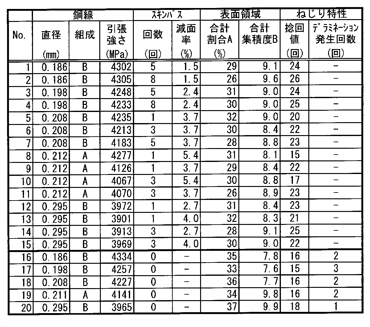
- Table 2 shows the torsion value of each sample. Additionally, the number of twists until delamination occurred was measured. If delamination occurs during a torsion test, the torque of the torsion tester will decrease. By measuring this torque, it is possible to check whether delamination has occurred. The number of times of twisting until delamination occurs in each sample is shown in the "Number of times delamination occurs" column in Table 2. If breakage occurred without delamination occurring, the "Number of delamination occurrences" column was set as "-".
- sample No. 1 was subjected to skin pass one or more times.
- 1 to No. Steel wire No. 15 has a twist value of 15 times or more, and no delamination occurs before breaking. Therefore, sample no. 1 to No. 15 steel wire has high torsional properties.
- Sample No. 1 to No. Among the 15 steel wires, sample No. 8 and no. All steel wires except No. 10 have twist values greater than or equal to 20 times and have higher torsional properties.
- sample No. 1 to No. Steel wire No. 15 has a tensile strength of 3900 MPa or more, and also has high tensile strength. Sample No. 1 to No. Steel wire No. 15 has high strength and excellent torsional properties.
- Sample No. 1 to No. All of the 15 steel wires have a specific structure in their surface regions. Specifically, these steel wires have a total percentage A of 32% or less. In addition, the total integration degree B of these steel wires also satisfies the range of 8.00 or more and 9.70 or less.
- sample No. 1 was not subjected to skin pass. 16 to no.
- the steel wire No. 20 had a twist value of 15 times or more, delamination occurred before it broke. In these steel wires, delamination occurred three times or less, and delamination occurred at an early stage. Furthermore, among these steel wires, the one with the largest twist value is 18 times.
- Sample No. 16 to no. Steel wire No. 20 has poor torsional properties. Sample No. 16 to no. All of the 20 steel wires have a total percentage A of 33% or more. In addition, the total integration degree B of these steel wires is also out of the range of 8.00 or more and 9.70 or less.
- the steel wire whose surface region has a specific structure has both high strength and toughness. Furthermore, it can be seen that such a steel wire can be obtained by performing a skin pass after the final wire drawing process.
- Test Example 1 reveal the following.
- the area reduction rate of the skin passes is the same, the greater the number of skin passes, the smaller the total ratio A tends to be. This is true, for example, for sample no. 5, No. 6, and no. This can be seen from the comparison of 7.
- sample No. 8 and no Comparison with sample no. 10 and no. From the comparison with No. 11, it is considered that the total ratio A can be further reduced if the area reduction rate of the skin pass is 5% or less.
Landscapes
- Chemical & Material Sciences (AREA)
- Engineering & Computer Science (AREA)
- Mechanical Engineering (AREA)
- Organic Chemistry (AREA)
- Materials Engineering (AREA)
- Metallurgy (AREA)
- Crystallography & Structural Chemistry (AREA)
- Thermal Sciences (AREA)
- Physics & Mathematics (AREA)
- Manufacturing & Machinery (AREA)
- Heat Treatment Of Steel (AREA)
- Heat Treatment Of Strip Materials And Filament Materials (AREA)
- Metal Extraction Processes (AREA)
Abstract
Description
0.9質量%以上1.1質量%以下の炭素と、
0.15質量%以上0.25質量%以下のシリコンと、
0.25質量%以上0.35質量%以下のマンガンと、
0.15質量%以上0.25質量%以下のクロムと、を含み、
残部が鉄、及び不可避不純物である鋼からなり、
前記鋼はパーライト組織を有し、
前記鋼線の直径は0.05mm以上0.45mm以下であり、
前記鋼線の引張強さは3900MPa以上4700MPa以下であり、
前記鋼線の縦断面において、前記鋼線の表面から前記直径の10%の深さまでの表面領域の組織は、
<100>方位の集合組織の割合A100と、<110>方位の集合組織の割合A110と、<111>方位の集合組織の割合A111との合計割合Aが32%以下である組織を有し、
前記割合A100は、前記表面領域の観察視野において、全ての結晶粒のうち、<100>方位が所定の配向を有する結晶粒の面積率であり、
前記割合A110は、前記表面領域の観察視野において、全ての結晶粒のうち、<110>方位が所定の配向を有する結晶粒の面積率であり、
前記割合A111は、前記表面領域の観察視野において、全ての結晶粒のうち、<111>方位が所定の配向を有する結晶粒の面積率である。
最初に本開示の実施態様を列記して説明する。
0.9質量%以上1.1質量%以下の炭素と、
0.15質量%以上0.25質量%以下のシリコンと、
0.25質量%以上0.35質量%以下のマンガンと、
0.15質量%以上0.25質量%以下のクロムと、を含み、
残部が鉄、及び不可避不純物である鋼からなり、
前記鋼はパーライト組織を有し、
前記鋼線の直径は0.05mm以上0.45mm以下であり、
前記鋼線の引張強さは3900MPa以上4700MPa以下であり、
前記鋼線の縦断面において、前記鋼線の表面から前記直径の10%の深さまでの表面領域の組織は、
<100>方位の集合組織の割合A100と、<110>方位の集合組織の割合A110と、<111>方位の集合組織の割合A111との合計割合Aが32%以下である組織を有し、
前記割合A100は、前記表面領域の観察視野において、全ての結晶粒のうち、<100>方位が所定の配向を有する結晶粒の面積率であり、
前記割合A110は、前記表面領域の観察視野において、全ての結晶粒のうち、<110>方位が所定の配向を有する結晶粒の面積率であり、
前記割合A111は、前記表面領域の観察視野において、全ての結晶粒のうち、<111>方位が所定の配向を有する結晶粒の面積率である。
前記表面領域の観察視野において、{100}面の集積度B100と{111}面の集積度B111との合計集積度Bが8.00以上9.70以下でもよい。
前記合計割合Aが29%以下でもよい。
前記合計集積度Bが8.40以上9.00以下でもよい。
前記鋼線の直径が0.15mm以上0.42mm以下でもよい。
前記鋼線の直径が0.18mm以上0.30mm以下でもよい。
前記鋼線の引張強さが3960MPa以上4500MPa以下でもよい。
0.9質量%以上1.1質量%以下の炭素と、0.15質量%以上0.25質量%以下のシリコンと、0.25質量%以上0.35質量%以下のマンガンと、0.15質量%以上0.25質量%以下のクロムと、を含み、残部が鉄、及び不可避不純物である鋼からなる素材を準備する工程と、
前記素材に第一伸線加工を行う工程と、
前記第一伸線加工が施された第一線材にパテンティング処理を行う工程と、
前記パテンティング処理が施された第一線材に第二伸線加工を行う工程と、
前記第二伸線加工が施された第二線材にスキンパスを行う工程と、を備える。
前記スキンパスを行う工程は、前記第二線材に前記スキンパスを1回以上8回以下行ってもよい。
前記スキンパスの1回あたりの減面率が1.0%以上6.0%以下でもよい。
本開示の実施形態に係る鋼線の具体例を説明する。
なお、本発明はこれらの例示に限定されるものではなく、請求の範囲によって示され、請求の範囲と均等の意味および範囲内でのすべての変更が含まれることが意図される。
本実施形態に係る鋼線は、縦断面において、表面領域が特定の組織を有する点を特徴の一つとする。図1を参照して、鋼線1は3次元直交座標系を用いて説明される。鋼線1の縦断面は、Y軸に平行で、かつ鋼線1の中心を通る断面である。表面領域10は、鋼線1の表面から鋼線1の直径の10%の深さまでの領域である。深さとは、鋼線1の表面から中心方向への距離である。本実施形態の鋼線1は、後述するように、表面領域10が特定の組織を有することで、表面領域10において特定の方向に配向した結晶粒が少ない。つまり、表面領域10の組織は、結晶方位がランダムに分布した状態である。その結果、本実施形態の鋼線1は、高強度でありながら、ねじり特性が向上する。
鋼線1は、0.9質量%以上1.1質量%以下の炭素(C)と、0.15質量%以上0.25質量%以下のシリコン(Si)と、0.25質量%以上0.35質量%以下のマンガン(Mn)と、0.15質量%以上0.25質量%以下のクロム(Cr)と、を含み、残部が鉄(Fe)、及び不可避不純物である鋼からなる。
鋼線1は、Cを0.9質量%以上1.1質量%以下含む。Cは鋼線1の強度を高める元素である。Cの含有量が多いほど、鋼線1の強度が向上する。一方、Cを過剰に含むと、鋼線1の靭性が低下する。Cの含有量は、例えば1.00質量%以上1.05質量%以下でもよい。
鋼線1の組成は、Siを0.15質量%以上0.25質量%以下含む。Siは、鋼の脱酸に有効な元素である。また、Siは、パーライト組織のフェライトに固溶して、鋼線1の強度を高める効果を有する。Siを過剰に含むと、鋼線1の靭性が低下する。Siの含有量は、例えば0.20質量%以上0.25質量%以下でもよく、0.20質量%以上0.23質量%以下でもよい。
鋼線1の組成は、Mnを0.25質量%以上0.35質量%以下含む。Mnは鋼の脱酸に有効な元素である。また、Mnは、鋼の焼入れ性を向上させ、鋼線1の強度を高める効果を有する。Mnを過剰に含むと、鋼線1の靭性が低下する。Mnの含有量は、例えば0.27質量%以上0.33質量%以下でもよく、0.30質量%でもよい。
鋼線1の組成は、Crを0.15質量%以上0.25質量%以下含む。Crは、パーライト組織のラメラ間隔を微細化することによって、鋼線1の強度を高める効果がある。Crを過剰に含むと、パーライト変態が起こり難くなる。Crの含有量は、例えば0.20質量%以上0.25質量%以下でもよく、0.20質量%以上0.21質量%以下でもよい。
鋼線1の組成は不可避不純物を含んでもよい。不可避不純物は、例えばリン(P)、硫黄(S)、及び銅(Cu)である。P及びSのそれぞれの含有量は0.025質量%以下が好ましい。
鋼線1の形状は適宜選択できる。本実施形態の鋼線1は、横断面が円形状の丸線である。鋼線1の横断面は、Y軸に直交する断面である。鋼線1の横断面の形状は非円形でもよい。非円形は、例えば多角形、楕円形である。多角形は、例えば長方形、六角形である。長方形には、正方形も含まれる。
鋼線1の直径は0.05mm以上0.45mm以下である。鋼線1の直径とは、鋼線1の横断面の面積と等しい面積を有する円の直径である。このような直径を有する鋼線1は、タイヤなどの補強材に好適に使用できる。鋼線1の直径は、0.15mm以上0.42mm以下でもよく、0.18mm以上0.30mm以下でもよい。
鋼線1の引張強さは3900MPa以上4700MPa以下である。このような引張強さを有する鋼線1は、高強度であり、タイヤなどの補強材に好適に使用できる。鋼線1の引張強さは、引張試験機を用いて一定の速度で鋼線1を引っ張り、鋼線1が破断するまでの最大応力である。例えば、鋼線1から取り出した200mmの試験片を、100mm/分の引張速度で引っ張り、試験片が破断するまでの引張強さを測定すればよい。鋼線1の引張強さは、3900MPa以上4400MPa以下でもよい。
鋼線1の組織は主にパーライト組織である。鋼線1は、上述した組成を有し、パーライト組織を有する鋼からなることで、高強度と靭性とを兼ね備えることができる。
(集合組織の合計割合)
本実施形態の鋼線1は、表面領域10において、特定の結晶面が特定の方位に配向した集合組織の割合が小さく、結晶方位がランダムに配向した組織を有する。表面領域10は、鋼線1の表面から鋼線1の直径の10%の深さまでの領域である。表面領域10は、鋼線1の表面から深さ5μm以上20μm以下の領域でもよい。
表面領域10の組織は、縦断面において、{100}面の集積度B100と{111}面の集積度B111との合計集積度Bが、例えば8.00以上9.70以下でもよい。合計集積度Bが8.00以上9.70以下である場合、高いねじり特性と高い引張強さとを両立できる。合計集積度Bは、8.10以上9.60以下、8.40以上9.00以下でもよい。集積度B100及び集積度B111はそれぞれ、例えば4.00以上5.50以下である。
本実施形態の鋼線1は、タイヤなどのゴム製品に埋め込まれる補強材に好適に使用できる。タイヤ以外のゴム製品は、例えば、コンベアベルト、エスカレータのハンドレール、ホースなどである。本実施形態の鋼線1は、高い引張強さを有することから、細くても強度を確保できるので、ゴム製品の軽量化を図ることができる。本実施形態の鋼線1は、高いねじり特性を有することから、撚り加工した際に鋼線1が断線し難く、鋼線1にデラミネーションが発生したりし難い。また、ゴム製品の使用中に鋼線1にねじれが発生しても、鋼線1が断線し難く、鋼線1にデラミネーションが発生したりし難い。
実施形態の鋼線1は、実施形態に係る鋼線の製造方法によって製造できる。実施形態の鋼線の製造方法は、第一工程と、第二工程と、第三工程と、第四工程と、第五工程とを備える。以下、各工程を詳しく説明する。
第一工程は、鋼からなる素材を準備する工程である。鋼の組成は、0.9質量%以上1.1質量%以下の炭素と、0.15質量%以上0.25質量%以下のシリコンと、0.25質量%以上0.35質量%以下のマンガンと、0.15質量%以上0.25質量%以下のクロムと、を含み、残部が鉄、及び不可避不純物である。素線の組成は、製造する鋼線の組成と同じである。素材は、連続鋳造法、連続鋳造圧延法などの方法により製造されたものである。素材は、例えば熱間圧延により、所定の直径となるように加工してもよい。素材の直径は、例えば4mm以上6mm以下である。素材の形状は、例えば、横断面が円形状の丸線である。
第二工程は、素材に第一伸線加工を行う工程である。第一伸線加工は、ダイスを使用して素材の直径が所定の直径になるまで、1回又は複数回行う。第一伸線加工は、例えば湿式で行う。第一伸線加工の1回あたりの減面率は、例えば10%以上20%以下である。1回あたりの減面率とは、素材が1つのダイスを通過するとき、ダイスを通過する前の素材の断面積とダイスを通過した後の素材の断面積との差を、ダイスを通過する前の素材の断面積で割った割合である。第二工程により、第一伸線加工が施された第一線材が得られる。第一線材の直径は、例えば1mm以上2.5mm以下である。
第三工程は、第一伸線加工が施された第一線材にパテンティング処理を行う工程である。パテンティング処理は、第一線材を構成する鋼をパーライト組織にするための熱処理である。パテンティング処理は、第一線材を加熱して鋼をオーステナイト組織にした後、第一線材を冷却して鋼をパーライト組織にする。具体的には、パテンティング処理は、まず、第一線材をオーステナイト化温度域に加熱した状態で一定時間保持して、鋼をオーステナイト化する。オーステナイト化温度域は、オーステナイト化温度以上の温度域、即ちAcm点以上の温度域である。オーステナイト化温度域は、例えば950℃以上1000℃以下である。オーステナイト化温度域の保持時間は、例えば5秒以上10秒以下である。次に、オーステナイト化した第一線材をパーライト変態温度域まで急冷して一定時間保持し、鋼をパーライト化する。パーライト変態温度域は、オーステナイト化温度よりも低く、マルテンサイト変態を開始する温度よりも高い温度域、即ちMs点以上の温度域である。パーライト変態温度域は、例えば500℃以上600℃以下である。パーライト変態温度域の保持時間は、例えば3秒以上10秒以下である。このようなパテンティング処理により、鋼が微細なパーライト組織になる。第一線材は、パーライト変態温度域に保持された後、常温まで冷却される。オーステナイト化する処理では、脱炭の発生を抑制するために、不活性ガス雰囲気中で第一線材を加熱してもよい。
第四工程は、パテンティング処理が施された第一線材に第二伸線加工を行う工程である。第二伸線加工は、ダイスを使用して第一線材の直径が製造する鋼線の直径に近い直径になるまで、1回又は複数回行う。第二伸線加工の条件は、第一伸線加工の条件と同様である。第四工程により、第二伸線加工が施された第二線材が得られる。第二線材の直径は、鋼線の直径よりも少し小さい直径である。第二線材の直径は、例えば0.05mm超0.45mm以下である。
第五工程は、第二伸線加工が施された第二線材にスキンパスを行う工程である。スキンパスは非常に小さい減面率で行う圧延加工である。スキンパスを施すことで、鋼線の表面領域における結晶粒の配向性を変化させることができる。この工程により、表面領域が特定の組織を有する本実施形態の鋼線1を得ることができる。
鋼線の試料を作製した。作製した鋼線の試料を評価した。
試料No.1からNo.15の鋼線は、上述した鋼線の製造方法によって作製した。ここでは、表1に示す組成A又は組成Bの鋼からなる素材を準備した。表1に示す各元素の含有量は、鋼に含まれる元素の合計含有量を100質量%とした値である。表1中、「Fe」の欄の「bal.」は、残部であることを表す。素材は、鋼を溶解鋳造した後、線状に熱間圧延して製造されたものである。素材の形状は丸線である。素材の直径は5.0mmである。
〈組織の分析〉
各試料の鋼線の組織を分析した。各試料の鋼線から分析用の測定片を作製した。測定片の長さは20mmである。測定片を樹脂に埋めた後、クロスセクションポリッシャを用いて測定片に断面加工を行い、鋼線の縦断面を露出させた。クロスセクションポリッシャの条件は、加速電圧:6kV、照射電流:130μAとした。断面の仕上げ加工は、加速電圧を1kVとした。
測定片の縦断面をFE-SEMによって観察し、FE-SEMに備えるEBSDによって表面領域の結晶方位を解析した。使用したEBSDは、Oxford Instruments社製Symmetryである。観察条件は、加速電圧:15kV、照射電流:10nAに設定した。EBSDの条件は、積算時間:0.3m秒、ビニング:4×4、作動距離(WD):15mm、ステップサイズ:0.04μm、チルト角:70°に設定した。観察した領域と観察視野のサイズは、組織を分析した範囲と同じである。
観察視野において、<100>方位の集合組織の割合A100と、<110>方位の集合組織の割合A110と、<111>方位の集合組織の割合A111をそれぞれ解析ソフトウェアによって求めた。そして、割合A100と割合A110と割合A111との合計割合Aを求めた。その結果を表2に示す。
更に、解析ソフトウェアによって、{100}面の極点図と{111}面の極点図を取得した。それぞれの極点図から、{100}面の集積度B100と{111}面の集積度B111を求めた。そして、集積度B100と集積度B111との合計集積度Bを求めた。その結果を表2に示す。
各試料の鋼線の引張強さを測定した。鋼線を切断して引張試験用の試験片を作製した。試験片の長さは200mmである。引張試験機を用いて、試験片を100mm/分の引張速度で引っ張り、試験片が破断するまでの引張強さを測定した。その結果を表2に示す。
各試料の鋼線のねじり特性を評価した。鋼線を切断してねじり試験用の試験片を作製した。試験片の長さは直径の100倍、即ち直径×100mmである。電動式ねじり試験機を用いて、試験片に張力をかけた状態で試験片を一方向にねじり、試験片が破断するまでのねじり回数を測定した。ねじり回数は1回転を1回とカウントする。このねじり回数を捻回値と呼ぶ。ねじり速度は30rpmとした。ねじり速度は1分間に回転する回数である。張力は鋼線の降伏応力の5%以下となるように設定した。鋼線の降伏応力は、引張試験によって求められる。各試料の捻回値を表2に示す。また、デラミネーションが発生するまでのねじり回数を測定した。ねじり試験中にデラミネーションが発生すると、ねじり試験機のトルクが低下する。このトルクを測定することでデラミネーションの発生の有無を確認できる。各試料におけるデラミネーションが発生するまでのねじり回数を、表2の「デラミネーション発生回数」の欄に示す。デラミネーションが発生せずに破断に至った場合は、「デラミネーション発生回数」の欄は「-」とした。

10 表面領域
30 観察視野
Claims (10)
- 鋼線であって、
0.9質量%以上1.1質量%以下の炭素と、
0.15質量%以上0.25質量%以下のシリコンと、
0.25質量%以上0.35質量%以下のマンガンと、
0.15質量%以上0.25質量%以下のクロムと、を含み、
残部が鉄及び不可避不純物である鋼からなり、
前記鋼はパーライト組織を有し、
前記鋼線の直径は0.05mm以上0.45mm以下であり、
前記鋼線の引張強さは3900MPa以上4700MPa以下であり、
前記鋼線の縦断面において、前記鋼線の表面から前記直径の10%の深さまでの表面領域の組織は、
<100>方位の集合組織の割合A100と、<110>方位の集合組織の割合A110と、<111>方位の集合組織の割合A111との合計割合Aが32%以下であり、
前記割合A100は、前記表面領域の観察視野において、全ての結晶粒のうち、<100>方位が所定の配向を有する結晶粒の面積率であり、
前記割合A110は、前記表面領域の観察視野において、全ての結晶粒のうち、<110>方位が所定の配向を有する結晶粒の面積率であり、
前記割合A111は、前記表面領域の観察視野において、全ての結晶粒のうち、<111>方位が所定の配向を有する結晶粒の面積率である、
鋼線。 - 前記表面領域の観察視野において、{100}面の集積度B100と{111}面の集積度B111との合計集積度Bが8.00以上9.70以下である、請求項1に記載の鋼線。
- 前記合計割合Aが29%以下である、請求項1または請求項2に記載の鋼線。
- 前記合計集積度Bが8.40以上9.00以下である、請求項2に記載の鋼線。
- 前記鋼線の直径が0.15mm以上0.42mm以下である、請求項1から請求項4までのいずれか一項に記載の鋼線。
- 前記鋼線の直径が0.18mm以上0.30mm以下である、請求項5に記載の鋼線。
- 前記鋼線の引張強さが3960MPa以上4500MPa以下である、請求項1から請求項6までのいずれか一項に記載の鋼線。
- 0.9質量%以上1.1質量%以下の炭素と、0.15質量%以上0.25質量%以下のシリコンと、0.25質量%以上0.35質量%以下のマンガンと、0.15質量%以上0.25質量%以下のクロムと、を含み、残部が鉄、及び不可避不純物である鋼からなる素材を準備する工程と、
前記素材に第一伸線加工を行う工程と、
前記第一伸線加工が施された第一線材にパテンティング処理を行う工程と、
前記パテンティング処理が施された第一線材に第二伸線加工を行う工程と、
前記第二伸線加工が施された第二線材にスキンパスを行う工程と、を備える、
鋼線の製造方法。 - 前記スキンパスを行う工程は、前記第二線材に前記スキンパスを1回以上8回以下行う、請求項8に記載の鋼線の製造方法。
- 前記スキンパスの1回あたりの減面率が1.0%以上6.0%以下である、請求項8または請求項9に記載の鋼線の製造方法。
Priority Applications (4)
| Application Number | Priority Date | Filing Date | Title |
|---|---|---|---|
| CN202380051553.7A CN119487230A (zh) | 2022-07-29 | 2023-07-03 | 钢线以及钢线的制造方法 |
| JP2023563798A JP7436964B1 (ja) | 2022-07-29 | 2023-07-03 | 鋼線、及び鋼線の製造方法 |
| DE112023003278.5T DE112023003278T5 (de) | 2022-07-29 | 2023-07-03 | Stahldraht und Verfahren zur Herstellung von Stahldraht |
| US18/873,479 US20250320589A1 (en) | 2022-07-29 | 2023-07-03 | Steel wire and method of manufacturing steel wire |
Applications Claiming Priority (2)
| Application Number | Priority Date | Filing Date | Title |
|---|---|---|---|
| JP2022-121882 | 2022-07-29 | ||
| JP2022121882 | 2022-07-29 |
Publications (1)
| Publication Number | Publication Date |
|---|---|
| WO2024024401A1 true WO2024024401A1 (ja) | 2024-02-01 |
Family
ID=89706082
Family Applications (1)
| Application Number | Title | Priority Date | Filing Date |
|---|---|---|---|
| PCT/JP2023/024538 Ceased WO2024024401A1 (ja) | 2022-07-29 | 2023-07-03 | 鋼線、及び鋼線の製造方法 |
Country Status (5)
| Country | Link |
|---|---|
| US (1) | US20250320589A1 (ja) |
| JP (1) | JP7436964B1 (ja) |
| CN (1) | CN119487230A (ja) |
| DE (1) | DE112023003278T5 (ja) |
| WO (1) | WO2024024401A1 (ja) |
Citations (6)
| Publication number | Priority date | Publication date | Assignee | Title |
|---|---|---|---|---|
| JPH02263951A (ja) * | 1988-12-28 | 1990-10-26 | Nippon Steel Corp | 高強度高延性鋼線材および高強度高延性極細鋼線の製造方法 |
| JPH06158224A (ja) * | 1992-11-30 | 1994-06-07 | Nippon Steel Corp | 高強度鋼線とその製造法 |
| WO2010150450A1 (ja) * | 2009-06-22 | 2010-12-29 | 新日本製鐵株式会社 | 高強度極細鋼線及びその製造方法 |
| WO2016024635A1 (ja) * | 2014-08-15 | 2016-02-18 | 新日鐵住金株式会社 | 伸線加工用鋼線 |
| JP2017186633A (ja) * | 2016-04-08 | 2017-10-12 | 新日鐵住金株式会社 | 鋼線、及びその鋼線の製造方法 |
| JP2022056005A (ja) * | 2020-09-29 | 2022-04-08 | 日本製鉄株式会社 | 鋼線とその製造方法 |
-
2023
- 2023-07-03 DE DE112023003278.5T patent/DE112023003278T5/de active Pending
- 2023-07-03 CN CN202380051553.7A patent/CN119487230A/zh active Pending
- 2023-07-03 WO PCT/JP2023/024538 patent/WO2024024401A1/ja not_active Ceased
- 2023-07-03 JP JP2023563798A patent/JP7436964B1/ja active Active
- 2023-07-03 US US18/873,479 patent/US20250320589A1/en active Pending
Patent Citations (6)
| Publication number | Priority date | Publication date | Assignee | Title |
|---|---|---|---|---|
| JPH02263951A (ja) * | 1988-12-28 | 1990-10-26 | Nippon Steel Corp | 高強度高延性鋼線材および高強度高延性極細鋼線の製造方法 |
| JPH06158224A (ja) * | 1992-11-30 | 1994-06-07 | Nippon Steel Corp | 高強度鋼線とその製造法 |
| WO2010150450A1 (ja) * | 2009-06-22 | 2010-12-29 | 新日本製鐵株式会社 | 高強度極細鋼線及びその製造方法 |
| WO2016024635A1 (ja) * | 2014-08-15 | 2016-02-18 | 新日鐵住金株式会社 | 伸線加工用鋼線 |
| JP2017186633A (ja) * | 2016-04-08 | 2017-10-12 | 新日鐵住金株式会社 | 鋼線、及びその鋼線の製造方法 |
| JP2022056005A (ja) * | 2020-09-29 | 2022-04-08 | 日本製鉄株式会社 | 鋼線とその製造方法 |
Also Published As
| Publication number | Publication date |
|---|---|
| JP7436964B1 (ja) | 2024-02-22 |
| US20250320589A1 (en) | 2025-10-16 |
| CN119487230A (zh) | 2025-02-18 |
| DE112023003278T5 (de) | 2025-05-22 |
| JPWO2024024401A1 (ja) | 2024-02-01 |
Similar Documents
| Publication | Publication Date | Title |
|---|---|---|
| JP4719320B2 (ja) | 高強度極細鋼線及びその製造方法 | |
| JP4943564B2 (ja) | ソーワイヤ用素線及びその製造方法 | |
| CN101331243B (zh) | 拉丝特性优良的高强度线材及其制造方法 | |
| EP3103891A1 (en) | Steel wire | |
| JP6237793B2 (ja) | フィラメント | |
| US20180087125A1 (en) | High-carbon steel wire material with excellent wire drawability, and steel wire | |
| JPWO2019004454A1 (ja) | 高強度鋼線 | |
| JP6828592B2 (ja) | 伸線加工用熱間圧延線材 | |
| JP4377715B2 (ja) | 捻回特性に優れた高強度pc鋼線 | |
| JP3777166B2 (ja) | 高強度極細鋼線の製造方法 | |
| JP7436964B1 (ja) | 鋼線、及び鋼線の製造方法 | |
| JP5573223B2 (ja) | 耐断線性に優れた高強度極細鋼線及びその製造方法 | |
| JP4464511B2 (ja) | 延性及び疲労特性の優れた高強度極細鋼線の製造方法 | |
| JP3814070B2 (ja) | 高強度極細鋼線およびその製造方法 | |
| JP3267833B2 (ja) | 疲労特性の優れた高強度極細鋼線およびその製造方法 | |
| JP3641056B2 (ja) | 高強度極細鋼線 | |
| JP3299857B2 (ja) | 疲労特性の優れた高強度極細鋼線およびその製造方法 | |
| JP4555711B2 (ja) | 延性に優れた高強度極細鋼線 | |
| JP2025104030A (ja) | 鋼線及び撚り線 | |
| JP7173410B1 (ja) | 鋼線およびばね | |
| JP2025104031A (ja) | 鋼線及びロープ | |
| JPH06346190A (ja) | 疲労特性に優れた極細鋼線 | |
| WO2022259606A1 (ja) | 鋼線およびばね |
Legal Events
| Date | Code | Title | Description |
|---|---|---|---|
| WWE | Wipo information: entry into national phase |
Ref document number: 2023563798 Country of ref document: JP |
|
| 121 | Ep: the epo has been informed by wipo that ep was designated in this application |
Ref document number: 23846134 Country of ref document: EP Kind code of ref document: A1 |
|
| WWE | Wipo information: entry into national phase |
Ref document number: 18873479 Country of ref document: US |
|
| WWE | Wipo information: entry into national phase |
Ref document number: 202380051553.7 Country of ref document: CN |
|
| WWE | Wipo information: entry into national phase |
Ref document number: 2501000236 Country of ref document: TH |
|
| WWP | Wipo information: published in national office |
Ref document number: 202380051553.7 Country of ref document: CN |
|
| WWE | Wipo information: entry into national phase |
Ref document number: 112023003278 Country of ref document: DE |
|
| WWP | Wipo information: published in national office |
Ref document number: 112023003278 Country of ref document: DE |
|
| 122 | Ep: pct application non-entry in european phase |
Ref document number: 23846134 Country of ref document: EP Kind code of ref document: A1 |
|
| WWP | Wipo information: published in national office |
Ref document number: 18873479 Country of ref document: US |