WO2024024025A1 - 樹脂成形品及び樹脂成形品の製造方法 - Google Patents
樹脂成形品及び樹脂成形品の製造方法 Download PDFInfo
- Publication number
- WO2024024025A1 WO2024024025A1 PCT/JP2022/029111 JP2022029111W WO2024024025A1 WO 2024024025 A1 WO2024024025 A1 WO 2024024025A1 JP 2022029111 W JP2022029111 W JP 2022029111W WO 2024024025 A1 WO2024024025 A1 WO 2024024025A1
- Authority
- WO
- WIPO (PCT)
- Prior art keywords
- distance
- resin
- molded
- plane
- molding
- Prior art date
- Legal status (The legal status is an assumption and is not a legal conclusion. Google has not performed a legal analysis and makes no representation as to the accuracy of the status listed.)
- Ceased
Links
Images




Classifications
-
- B—PERFORMING OPERATIONS; TRANSPORTING
- B29—WORKING OF PLASTICS; WORKING OF SUBSTANCES IN A PLASTIC STATE IN GENERAL
- B29C—SHAPING OR JOINING OF PLASTICS; SHAPING OF MATERIAL IN A PLASTIC STATE, NOT OTHERWISE PROVIDED FOR; AFTER-TREATMENT OF THE SHAPED PRODUCTS, e.g. REPAIRING
- B29C45/00—Injection moulding, i.e. forcing the required volume of moulding material through a nozzle into a closed mould; Apparatus therefor
- B29C45/14—Injection moulding, i.e. forcing the required volume of moulding material through a nozzle into a closed mould; Apparatus therefor incorporating preformed parts or layers, e.g. injection moulding around inserts or for coating articles
-
- B—PERFORMING OPERATIONS; TRANSPORTING
- B29—WORKING OF PLASTICS; WORKING OF SUBSTANCES IN A PLASTIC STATE IN GENERAL
- B29C—SHAPING OR JOINING OF PLASTICS; SHAPING OF MATERIAL IN A PLASTIC STATE, NOT OTHERWISE PROVIDED FOR; AFTER-TREATMENT OF THE SHAPED PRODUCTS, e.g. REPAIRING
- B29C45/00—Injection moulding, i.e. forcing the required volume of moulding material through a nozzle into a closed mould; Apparatus therefor
- B29C45/14—Injection moulding, i.e. forcing the required volume of moulding material through a nozzle into a closed mould; Apparatus therefor incorporating preformed parts or layers, e.g. injection moulding around inserts or for coating articles
- B29C45/14639—Injection moulding, i.e. forcing the required volume of moulding material through a nozzle into a closed mould; Apparatus therefor incorporating preformed parts or layers, e.g. injection moulding around inserts or for coating articles for obtaining an insulating effect, e.g. for electrical components
-
- B—PERFORMING OPERATIONS; TRANSPORTING
- B29—WORKING OF PLASTICS; WORKING OF SUBSTANCES IN A PLASTIC STATE IN GENERAL
- B29C—SHAPING OR JOINING OF PLASTICS; SHAPING OF MATERIAL IN A PLASTIC STATE, NOT OTHERWISE PROVIDED FOR; AFTER-TREATMENT OF THE SHAPED PRODUCTS, e.g. REPAIRING
- B29C45/00—Injection moulding, i.e. forcing the required volume of moulding material through a nozzle into a closed mould; Apparatus therefor
- B29C45/16—Making multilayered or multicoloured articles
- B29C45/1671—Making multilayered or multicoloured articles with an insert
-
- B—PERFORMING OPERATIONS; TRANSPORTING
- B29—WORKING OF PLASTICS; WORKING OF SUBSTANCES IN A PLASTIC STATE IN GENERAL
- B29L—INDEXING SCHEME ASSOCIATED WITH SUBCLASS B29C, RELATING TO PARTICULAR ARTICLES
- B29L2031/00—Other particular articles
- B29L2031/34—Electrical apparatus, e.g. sparking plugs or parts thereof
- B29L2031/3481—Housings or casings incorporating or embedding electric or electronic elements
-
- H—ELECTRICITY
- H10—SEMICONDUCTOR DEVICES; ELECTRIC SOLID-STATE DEVICES NOT OTHERWISE PROVIDED FOR
- H10W—GENERIC PACKAGES, INTERCONNECTIONS, CONNECTORS OR OTHER CONSTRUCTIONAL DETAILS OF DEVICES COVERED BY CLASS H10
- H10W74/00—Encapsulations, e.g. protective coatings
- H10W74/01—Manufacture or treatment
Definitions
- the present disclosure relates to a resin molded product and a method for manufacturing a resin molded product.
- resin molded products including connectors are known.
- the resin molded product disclosed in Patent Document 1 includes components such as a connector terminal, and a resin housing that is integrated with the connector terminal.
- the housing has a fitting portion for a mating connector to be connected to the connector terminal.
- Such resin molded products are manufactured by injection molding using parts such as connector terminals as inserts.
- the resin molded products as described above there are a plurality of resin molded products whose connector terminals have different shapes but are the same in other respects, or a plurality of resin molded products whose fitting portions have different shapes but are the same in other respects.
- a plurality of molds are required for each resin molded product.
- Each of the plurality of molds has a slightly different shape in only a portion thereof, while the shape of most of the molds is the same.
- a large amount of cost is required to manufacture and manage a large number of molds.
- an object of the present disclosure is to provide a resin molded product that enables reduction of mold cost, and to provide a method for manufacturing such a resin molded product.
- the resin molded product of the present disclosure is It has a first molding part and a second molding part,
- the first molded part has a part as an insert and a first resin part that is integrated with the part,
- the second molded part has a second resin part,
- the first resin part includes a first surface, a second surface, a third surface, and a fourth surface, the first surface is annular;
- the second surface is a surface including the normal to the first surface,
- the second surface is annular along the first surface, the second surface is located adjacent to the first surface,
- the third surface is recessed in the normal direction of the first surface,
- the third surface is annular along the first surface,
- the third surface is arranged adjacent to the first surface on the opposite side of the second surface,
- the fourth surface is recessed in the normal direction of the second surface,
- the fourth surface is annular along the second surface,
- the fourth surface is arranged adjacent to the second surface on the opposite side of the first surface,
- the method for manufacturing a resin molded article of the present disclosure is the method for manufacturing the resin molded article, comprising: a preparation step of arranging the first molding part in a mold; a molding step of supplying molten resin to the mold to mold the second molding part; When the molten resin solidifies, a demolding step of removing the resin molded product in which the first molded part and the second molded part are integrated from the mold; has.
- the sealing property between the first resin part and the second resin part is good, and moisture is removed from the external space into the gap between the first resin part and the second resin part. difficult to penetrate.
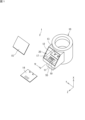
- FIG. 1 is a perspective view showing an example of a resin molded product.
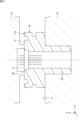
- FIG. 2 is an explanatory diagram of a method for manufacturing a resin molded product.
- FIG. 3 is an explanatory diagram of a preparation process for secondary injection molding.
- FIG. 4 is an explanatory diagram of the molding process of secondary injection molding.
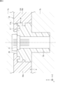
- FIG. 5 is a cross-sectional view of a part of the resin molded product.
- FIG. 6 is an explanatory diagram of a resin molded product that has undergone secondary injection molding.
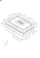
- FIG. 7 is a perspective view of the first molding section.
- FIG. 8 is a cross-sectional view showing a part of FIG. 5 in an enlarged manner.
- the resin molded product of the present disclosure is It has a first molding part and a second molding part,
- the first molded part has a part as an insert and a first resin part that is integrated with the part,
- the second molded part has a second resin part,
- the first resin part includes a first surface, a second surface, a third surface, and a fourth surface, the first surface is annular;
- the second surface is a surface including the normal to the first surface,
- the second surface is annular along the first surface, the second surface is located adjacent to the first surface,
- the third surface is recessed in the normal direction of the first surface,
- the third surface is annular along the first surface,
- the third surface is arranged adjacent to the first surface on the opposite side of the second surface,
- the fourth surface is recessed in the normal direction of the second surface,
- the fourth surface is annular along the second surface,
- the fourth surface is arranged adjacent to the second surface on the opposite side of the first surface,
- the sealing property between the first resin part and the second resin part is good, and moisture is removed from the external space into the gap between the first resin part and the second resin part. difficult to penetrate.
- the bonding strength between the first molded part and the second molded part and the sealing performance between them become issues. Intrusion of moisture in the air causes deterioration such as corrosion of the first resin part, the second resin part, and the insert.
- the resin molded product of the present disclosure can solve these problems.
- the method for manufacturing a resin molded article of the present disclosure is the method for manufacturing a resin molded article according to (1A) above, comprising: a preparation step of arranging the first molding part in a mold; a molding step of supplying molten resin to the mold to mold the second molding part; When the molten resin solidifies, a demolding step of removing the resin molded product in which the first molded part and the second molded part are integrated from the mold; has.
- the molding of the first molded part is All you have to do is change the mold.
- the mold for molding the second molding part can be common. Therefore, it is possible to reduce mold costs. It becomes possible to improve the strength between the first resin part and the second resin part and the sealing performance between them.
- the resin molded product of the present disclosure from another perspective, a first molded part having a part as an insert and a first resin part integral with the part; a second molded part that is integral with the first molded part as an insert, The second molded part has a second resin part that covers at least a peripheral edge of the first resin part, As a bonding interface between the first resin part and the second resin part, a first interface; an annular second interface having a surface that is continuous from the entire circumferential edge of the first interface and intersects with the first interface; a first concave interface recessed from the first interface; a second concave interface recessed from the second interface; has The first concave interface is formed in an annular shape along an edge region of the first interface, The second concave interface is formed in an annular shape along the second interface within a range overlapping with the edge region.
- the mold for molding the first molded part when the shape of the part included in the first molded part or the part of the first resin part surrounding the part varies, the mold for molding the first molded part is changed. Just change it.
- the mold for molding the second molding part can be common. Therefore, it is possible to reduce the mold cost compared to the conventional method.
- the first concave interface and the second concave interface are concave in different directions.
- the first concave interface is located in the edge region of the first interface, and the second concave interface is located within the range that overlaps the edge region, so the first concave interface and the second concave interface are close to each other. ing.
- the resin of the second resin portion enters and contacts the first concave interface and the second concave interface. Therefore, the shrinkage of the second resin part during molding makes it possible to increase the strength of the joint between the first resin part and the second resin part and the airtightness between them.
- the first interface has a first surface that is planar
- the second interface has a second surface that is planar orthogonal to the first surface
- the first concave surface has a third surface located opposite to the second surface and perpendicular to the first surface
- the second concave surface is opposite to the first surface. It has a fourth surface located on the side and perpendicular to the second surface.
- the first surface and the second surface are perpendicular to each other.
- the third surface is a surface perpendicular to the first surface
- the fourth surface is a surface perpendicular to the second surface.
- the distance between the second surface and the third surface along the first surface is a first distance
- the distance between the first surface and the fourth surface is preferably a first distance
- the distance along the second surface between the first surface and the third surface is defined as the second distance
- the distance between the first surface and the third surface is the distance between the first surface and the third surface.
- the distance along the third surface is defined as the third distance
- the method for manufacturing a resin molded article of the present disclosure from another perspective is the method for manufacturing a resin molded article according to any one of (1B) to (3B) above, a preparation step of arranging the first molding part in a mold; a molding step of supplying molten resin to the mold to mold the second molding part; When the molten resin hardens, the resin molded product in which the first molded part and the second molded part are integrated is removed from the mold; has.
- the molding of the first molded part is All you have to do is change the mold.
- the mold for molding the second molding part can be common. Therefore, it is possible to reduce mold costs. It becomes possible to increase the strength of the joint between the first resin part and the second resin part and the airtightness between them.
- FIG. 1 is a perspective view showing an example of a product.
- the product 1 shown in FIG. 1 includes a resin molded product 10, a substrate 14, and a lid 15.
- the resin molded product 10 includes a connector terminal 11 as a first component, a sensor 12 as a second component, and a housing 13. Connector terminal 11, sensor 12, and housing 13 are not separated.
- the board 14 is attached to the housing 13.
- the lid 15 is fixed to the housing 13.
- FIG. 1 shows a product 1 in which a substrate 14, a lid 15, and a resin molded product 10 are separated.
- Product 1 is a sensor device.
- the housing 13 is made of resin.
- the resin molded product 10 is a composite component in which a housing 13, a connector terminal 11, and a sensor 12 are integrally molded by injection molding.
- the resin molded product 10 can be divided into a first molded part 16 and a second molded part 18.
- Injection molding includes primary injection molding and secondary injection molding.
- FIG. 2 is an explanatory diagram of a method for manufacturing the resin molded product 10.
- the primary injection molding is an injection molding in which the connector terminal 11 is used as an insert and the first resin part 17 is integrally molded.
- the first molded part 16 is a part that includes the connector terminal 11 (component) and the first resin part 17.
- the connector terminal 11 (component) and the first resin portion 17 are integrated.
- the secondary injection molding is an injection molding in which the first molded part 16 and the sensor 12 are used as inserts, and the second resin part 19 is molded.
- the second molded part 18 is a part that includes the sensor 12 and the second resin part 19.
- the resin molded product 10 is manufactured by secondary injection molding.
- the resin molded product 10 is a composite component in which a first molded part 16 and a second molded part 18 are integrated.
- Housing 13 includes a first resin part 17 and a second resin part 19.
- the housing has a fitting part 55 in the first resin part 17.
- the connector terminal 11 is fixed to a fitting portion 55 of the housing 13.
- a mating connector (not shown) fits into the fitting portion 55.
- the mating connector is different from the resin molded product 10. When the fitting portion 55 and the mating connector are connected, the connector terminals 11 are connected to the mating connector terminals of the mating connector.
- FIG. 3 and 4 are explanatory diagrams of secondary injection molding.
- FIG. 3 shows a preparation process for arranging the first molding part 16 in the molds 7a and 7b.
- the first molding part 16 and the sensor 12 (not shown in FIG. 3) are arranged at predetermined positions of the molds 7a and 7b.
- FIG. 4 shows that after arranging the first molding part 16 and the sensor 12 as inserts in the cavities 8 of the molds 7a and 7b, the second resin part 19 is integrally molded by supplying molten resin 19a.
- the molding process is shown.
- the secondary injection molding is an injection molding in which the molten resin 19a supplied into the cavity 8 is solidified.
- the first molded part 16 and the second molded part 18 become integrated by solidifying the molten resin 19a.
- FIG. 5 is a cross-sectional view of a part of the resin molded product 10 obtained after being removed from the molds 7a and 7b.
- FIG. 5 is a sectional view taken in the direction of arrow V in FIG.
- the resin molded product 10 in which the first molded part 16 and the second molded part 18 are integrated is taken out from the molds 7a and 7b.
- the process in which the resin molded product 10 in which the first molded part 16 and the second molded part 18 are integrated is taken out from the molds 7a and 7b is a take-out process.
- the solidified portion of the molten resin 19a is the second resin portion 19.
- the second resin part 19 covers a part of the first resin part 17.
- a resin molded product 10 manufactured by secondary injection molding has a housing space 20.
- the board 14 is installed in the accommodation space 20.
- the board 14 is electrically connected to the connector terminal 11.
- the substrate 14 is electrically connected to the sensor 12.
- the lid 15 closes the accommodation space 20.
- the lid 15 made of resin is fixed to the resin molded product 10 by, for example, laser welding.
- the accommodation space 20 becomes a closed space.
- the process of attaching the substrate 14 to the resin molded product 10 and fixing the lid 15 to the resin molded product 10 is an assembly process.
- the preparation process is a process of arranging the first molded part 16 manufactured by primary injection molding in the molds 7a and 7b.
- the molding process is a process of supplying the molten resin 19a to the molds 7a and 7b, solidifying the molten resin 19a, and molding the second molded part 18.
- the taking-out process is a process of taking out the resin molded product 10, in which the first molded part 16 and the second molded part 18 are integrated, from the molds 7a and 7b.
- the assembly process is a process of assembling the substrate 14 and the lid 15 onto the resin molded product 10. Product 1 is completed through four steps.
- the X direction is a direction perpendicular to the plane containing the rectangle.
- the Y direction is a direction perpendicular to the X direction and along the long sides of the rectangle.
- the Z direction is a direction perpendicular to the X direction and the Y direction and along the short sides of the rectangle.
- Each figure shows the X direction, Y direction, and Z direction, respectively.
- the arrow head side of the arrow in the X direction in each figure is the first side in the X direction, and the side opposite to the arrow head is the second side in the X direction.
- the arrowhead side of the Y-direction arrow in each figure is the first side in the Y-direction, and the side opposite to the arrowhead is the second side in the Y-direction.
- the arrowhead side of the Z-direction arrow in each figure is the first side in the Z-direction, and the side opposite to the arrowhead is the second side in the Z-direction.
- the first molded part 16 of the resin molded product 10 includes the connector terminal 11 as the first component, and the second molded part 18 includes the sensor 12 as the second component.
- the second part may be omitted.
- the first component may be a component other than the connector terminal 11.
- the second component may be other than the sensor 12.
- the first molded part 16 is manufactured by primary injection molding.
- the first molded part 16 has a connector terminal 11 as an insert and a first resin part 17 that is integral with the connector terminal 11.
- the second molded part 18 is manufactured by secondary injection molding.
- the second molded part 18 has a second resin part 19 that is integrated with the first molded part 16 as an insert.
- FIG. 6 is an explanatory diagram of the resin molded product 10 that has undergone secondary injection molding.
- FIG. 6 is an image diagram in which the first molding part 16 is separated from the second molding part 18 in order to distinguish and explain the first molding part 16.
- the molten resin 19a molded by secondary injection molding becomes the second resin part 19 of the second molded part 18 by solidifying.
- the second resin part 19 covers a part of the first resin part 17.
- the second resin portion 19 has an annular portion.
- the annular portion covers the first resin portion 17 in an annular manner.
- the second resin part 19 covers at least a part of the first resin part 17 in an annular shape.
- the first resin part 17 includes a first groove 26 and a second groove 27.
- the first groove 26 is an annular groove recessed in the X direction from a plane whose perpendicular direction is the X direction.
- the second groove 27 is an annular groove having a groove portion recessed from two planes whose perpendicular direction is the Y direction, and a groove portion recessed from each of the two planes whose perpendicular direction is the Z direction. It's a groove.
- the second resin portion 19 completely fills the first groove 26 and the second groove 27. As shown in FIG. The second resin portion 19 is in contact with each surface forming the first groove 26 and each surface forming the second groove 27.
- the first resin portion 17 includes a first surface 31 , a second surface 32 , a third surface 33 , and a fourth surface 34 .
- the third surface 33 is a surface adjacent to the first surface 31 of the first groove 26 .
- the fourth surface 34 is a surface adjacent to the second surface 32 of the second groove 27 .
- the first resin portion 17 further includes a fifth surface 35, a sixth surface 36, a seventh surface 37, an eighth surface 38, a ninth surface 39, and a tenth surface 40. , is provided.
- the fifth surface 35 is a surface opposite to the first surface 31 of the first groove 26 .
- the fifth surface 35 and the first surface 31 are on the same plane.
- Each surface of the sixth surface 36 is a surface opposite to each surface of the second surface 32 of the second groove 27.
- Each surface of the sixth surface 36 and each surface of the second surface 32 are on the same plane.
- the seventh surface 37 is a surface adjacent to the fifth surface 35 of the first groove 26 .
- the eighth surface 38 is a surface between the third surface 33 and the fifth surface 35.
- Each surface of the ninth surface 39 is a surface adjacent to each surface of the sixth surface 36 of the second groove 27, respectively.
- Each surface of the tenth surface 40 is a surface between each surface of the fourth surface 34 and each surface of the ninth surface 39.
- the first surface 31 is an annular first plane perpendicular to the X-axis.
- the first surface 31 is parallel to the Y axis and parallel to the Z axis.
- the first surface 31 is an annular surface between the first circumference 61 and the second circumference 62.
- the first periphery 61 has a rectangular first long side 61a, a second long side 61b, a first short side 61c, and a second short side 61d.
- the second periphery 62 has a rectangular third long side 62a, a fourth long side 62b, a third short side 62c, and a fourth short side 62d.
- the third long side 62a and the fourth long side 62b are located between the first long side 61a and the second long side 61b.
- the first long side 61a, the second long side 61b, the third long side 62a, and the fourth long side 62b are on the same plane and parallel to each other.
- the third short side 62c and the fourth short side 62d are located between the first short side 61c and the second short side 61d.
- the first short side 61c, the second short side 61d, the third short side 62c, and the fourth short side 62d are on the same plane and parallel to each other.
- the second surface 32 is a surface whose perpendicular line is a direction perpendicular to the X-axis.
- the second surface 32 is a surface including the normal to the first surface 31.
- the second surface 32 is an annular surface along the first surface 31.
- the second surface 32 is an annular surface between the first circumference 61 and the third circumference 63.
- the third circumference 63 coincides with the circumference obtained by moving the first circumference 61 to the second side in the X direction.
- the third periphery 63 includes a rectangular fifth long side 63a, a sixth long side 63b, a fifth short side 63c, and a sixth short side 63d.
- the fifth long side 63a is located on the second side of the first long side 61a in the X direction.
- the sixth long side 63b is located on the second side of the second long side 61b in the X direction.
- the fifth short side 63c is located on the second side of the first short side 61c in the X direction.
- the sixth short side 63d is located on the second side of the second short side 61d in the X direction.
- a second plane 72 is located between the first long side 61a and the fifth long side 63a.
- a third plane 73 is located between the second long side 61b and the sixth long side 63b.
- a fourth plane 74 is located between the first short side 61c and the fifth short side 63c.
- a fifth plane 75 is located between the second short side 61d and the sixth short side 63d.
- the second surface 32 has a second plane 72 , a third plane 73 , a fourth plane 74 , and a fifth plane 75 .
- the third surface 33 is a surface opposite to the second surface 32 with respect to the first surface 31.
- the third surface 33 is depressed in the normal direction of the first surface 31.
- the third surface 33 is a side surface of the first groove 26.
- the third surface 33 is an annular surface along the first surface 31.
- the third surface 33 is an annular surface between the second circumference 62 and the fourth circumference 64.
- the fourth circumference 64 coincides with the circumference obtained by moving the second circumference 62 to the second side in the X direction.
- the fourth periphery 64 includes a seventh long side 64a, an eighth long side 64b, a seventh short side 64c, and an eighth short side 64d of the rectangle.
- the seventh long side 64a is located on the second side of the third long side 62a in the X direction.
- the eighth long side 64b is located on the second side of the fourth long side 62b in the X direction.
- the seventh short side 64c is located on the second side of the third short side 62c in the X direction.
- the eighth short side 64d is located on the second side of the fourth short side 62d in the X direction.
- a sixth plane 76 is located between the third long side 62a and the seventh long side 64a.
- a seventh plane 77 is located between the fourth long side 62b and the eighth long side 64b.
- An eighth plane 78 is located between the third short side 62c and the seventh short side 64c.
- a ninth plane 79 is located between the fourth short side 62d and the eighth short side 64d.
- the third surface 33 has a sixth plane 76 , a seventh plane 77 , an eighth plane 78 , and a ninth plane 79 .
- the fourth surface 34 is on the opposite side of the first surface 31 with respect to the second surface 32.
- the fourth surface 34 is recessed in the normal direction of the second surface.
- the fourth surface 34 is a side surface of the second groove 27.
- the fourth surface 34 is an annular tenth plane 80 along the second surface 32 .
- the fourth surface 34 is an annular surface between the third circumference 63 and the fifth circumference 65.
- the fifth circumference 65 includes a ninth long side 65a, a tenth long side 65b, a ninth short side 65c, and a tenth short side 65d of the rectangle.
- the ninth long side 65a is located on the first side of the fifth long side 63a in the Z direction.
- the tenth long side 65b is located on the second side of the sixth long side 63b in the Z direction.
- the ninth short side 65c is located on the first side of the fifth short side 63c in the Y direction.
- the tenth short side 65d is located on the second side of the sixth short side 63d in the Y direction.
- the ninth long side 65a and the tenth long side 65b are located between the fifth long side 63a and the sixth long side 63b.
- the fifth long side 63a, the sixth long side 63b, the ninth long side 65a, and the tenth long side 65b are on the same plane and parallel to each other.
- the ninth short side 65c and the tenth short side 65d are located between the fifth short side 63c and the sixth short side 63d.
- the fifth short side 63c, the sixth short side 63d, the third short side 65c, and the fourth short side 65d are on the same plane and parallel to each other.
- the first distance L1 is the distance on the first surface 31 in the normal direction of the second surface 32 of any point on the first circumference 61, and is the distance between the second surface 32 and the third surface 33. is the distance.
- the first distance L1 is the distance on the first plane 31 in the normal direction of the second plane 72 of any point on the first long side 61a, and is the distance between the first long side 61a and the third long side. Including the distance to the side 62a.
- the first distance L1 is the distance on the first plane 31 in the normal direction of the third plane 73 of any point on the second long side 61b, and is the distance between the second long side 61b and the fourth long side. Including the distance to the side 62b.
- the first distance L1 is the distance on the first plane 31 in the normal direction of the fourth plane 74 of any point on the first short side 61c, and is the distance between the first short side 61c and the third short side. Including the distance to the side 62c.
- the first distance L1 is the distance on the first plane 31 in the normal direction of the fifth plane 75 of any point on the second short side 61d, and is the distance between the second short side 61d and the fourth short side. Including the distance to the side 62d.
- the second distance L2 is the distance on the second surface 32 in the normal direction of the first surface 31 of any point on the first circumference 61, and is the distance between the first surface 31 and the fourth surface 34. is the distance.
- the second distance L2 is the distance on the second plane 72 in the normal direction of the first plane 31 of any point on the first long side 61a, and is the distance between the first long side 61a and the fifth long side. Including the distance to the side 63a.
- the second distance L2 is the distance on the third plane 73 in the normal direction of the first plane 31 of any point on the second long side 61b, and is the distance between the second long side 61b and the sixth long side. Including the distance to the side 63b.
- the second distance L2 is the distance on the fourth plane 74 in the normal direction of the first plane 31 of any point on the first short side 61c, and is the distance between the first short side 61c and the fifth short side. Including the distance to the side 63c.
- the second distance L2 is the distance on the fifth plane 75 in the normal direction of the first plane 31 of any point on the second short side 61d, and is the distance between the second short side 61d and the sixth short side. Including the distance to side 63d.
- the third distance L3 is the distance on the third surface 33 in the normal direction of the first surface 31 of any point on the second circumference 62, and is the distance between the first surface 31 and the first surface 31. This is the distance from the farthest position.
- the third distance L3 is the distance on the sixth plane 76 in the normal direction of the first plane 31 of any point on the third long side 62a, and is the distance between the third long side 62a and the seventh length. Including the distance to the side 64a.
- the third distance L3 is the distance on the seventh plane 77 in the normal direction of the first plane 31 of any point on the fourth long side 62b, and is the distance between the fourth long side 62b and the eighth long side. Including the distance to the side 64b.
- the third distance L3 is the distance on the eighth plane 78 in the normal direction of the first plane 31 of any point on the third short side 62c, and is the distance between the third short side 62c and the seventh short side. Including the distance to the side 64c.
- the third distance L3 is the distance on the ninth plane 79 in the normal direction of the first plane 31 of any point on the fourth short side 62d, and is the distance between the fourth short side 62d and the eighth short side. Including the distance to the side 64d.
- the fourth distance L4 is the distance on the fourth surface 34 in the normal direction of the second surface 32 of any point on the third circumference 63, and is the distance between the second surface 32 and the second surface 32. This is the distance from the farthest position.
- the fourth distance L4 is the distance on the tenth plane 80 in the normal direction of the second plane 72 of any point on the fifth long side 63a, and is the distance between the fifth long side 63a and the ninth long side. Including the distance to the side 65a.
- the fourth distance L4 is the distance on the tenth plane 80 in the normal direction of the third plane 73 of any point on the sixth long side 63b, and is the distance between the sixth long side 63b and the tenth long side. Including the distance to side 65b.
- the fourth distance L4 is the distance on the tenth plane 80 in the normal direction of the fourth plane 74 of any point on the fifth short side 63c, and is the distance between the fifth short side 63c and the ninth short side. Including the distance to side 65c.
- the fourth distance L4 is the distance on the tenth plane 80 in the normal direction of the fifth plane 75 of any point on the fifth short side 63d, and is the distance between the sixth short side 63d and the tenth short side. Including the distance to side 65d.
- the second resin part 19 is applied to all of the first surface 31, second surface 32, third surface 33, and fourth surface 34 of the first resin part 17. are in contact with each other.
- each of the first surface 31, second surface 32, third surface 33, and fourth surface 34 of the first resin part 17 is in contact with the second resin part 19. It is an interface.
- the second resin part 19 is in contact with all surfaces of the first groove 26 and the second groove 27 of the first resin part 17.
- the first surface 31 and the second surface 32 are connected at a corner.
- the locus of this corner is the first circumference 61.
- the first surface 31 and the third surface 33 are connected at a corner.
- the locus of this corner is the second circumference 62.
- the second surface 32 and the fourth surface 34 are connected at a corner.
- the locus of this corner is the third circumference 63.
- the bonding interface 25 between the first resin part 17 and the second resin part 19 includes a first interface 21 , a second interface 22 , a first concave interface 23 , and a second concave interface 24 .
- the second resin portion 19 covers the entire surface of the first interface 21 and the entire surface of the second interface 22.
- the second resin portion 19 covers the entire surface of the first concave interface 23 and the entire surface of the second concave interface 24.
- the first interface 21 is a part of the upper surface 29 of the first molded part 16 facing in the X direction.
- the second resin part 19 has an annular part that covers the peripheral edge 17a of the first resin part 17 (see FIGS. 5 and 6).
- the first interface 21 is an annular surface centered on the center reference line C in the X direction.
- the first interface 21 has a first surface 31 that is planar. Furthermore, the first interface 21 has a fifth surface 35 opposite to the first surface 31 with the first concave interface 23 in between.
- the second interface 22 is a Y direction, a direction opposite to the Y direction, a Z direction, and a side surface facing in a direction opposite to the Z direction. That is, the second interface 22 becomes an annular (cylindrical) surface.
- the second interface 22 has a second surface 32.
- the second surface 32 is continuous from the edge 21 a around the entire circumference of the first interface 21 and intersects with the first interface 21 .
- the second surface 32 is a plane orthogonal to the first surface 31.
- the second interface 22 has a sixth surface 36 opposite to the second surface 32 with the second concave interface 24 in between.
- the second interface 22 has four planar second surfaces 32 as surfaces facing in the Y direction, the opposite direction to the Y direction, the Z direction, and the opposite direction to the Z direction.
- the second surface 32 is a surface that extends in a direction perpendicular to the first surface 31 (first interface 21).
- the second interface 22 has four planar sixth surfaces 36 that face in the same direction as the second surface 32.
- FIG. 7 is a perspective view of the first molding section 16.
- the first concave interface 23 is a surface that is depressed from the first interface 21.
- the first concave interface 23 is continuous along the annular first interface 21.
- the first concave interface 23 is an annular first groove 26 when the first molded part 16 is viewed alone.
- FIG. 8 is a cross-sectional view showing a part of FIG. 5 in an enlarged manner.
- the first concave interface 23 has a third surface 33, a first opposing surface (seventh surface 37), and a first bottom surface (eighth surface 38).
- the third surface 33 is located on the opposite side to the second surface 32 and is orthogonal to the first surface 31.
- the first opposing surface (seventh surface 37) is a surface that faces the third surface 33.
- the first bottom surface (eighth surface 38) is the bottom surface of the first groove 26, and connects the third surface 33 and the first opposing surface (seventh surface 37).
- the second concave interface 24 is a surface that is concave from the second interface 22.
- the second concave interface 24 is continuous along the annular second interface 22.
- the second concave interface 24 is an annular second groove 27 when the first molded portion 16 is viewed alone.
- the second concave interface 24 has a fourth surface 34, a second opposing surface (ninth surface 39), and a second bottom surface (tenth surface 40).
- the fourth surface 34 is located on the opposite side of the first surface 31 and is orthogonal to the second surface 32.
- the second opposing surface (ninth surface 39) is a surface that faces the fourth surface 34.
- the second bottom surface (tenth surface 40) is the bottom surface of the second groove 27, and connects the fourth surface 34 and the second opposing surface (ninth surface 39).
- the first concave interface 23 and the second concave interface 24 are arranged close to each other.
- the first concave interface 23 is formed in an annular shape along the edge region K1 of the first interface 21.
- the second concave interface 24 is formed in an annular shape along the second interface 22 within a range overlapping with the edge region K1.
- the second concave interface 24 is formed within a range overlapping with the edge region K1 of the first interface 21 in the Z direction, the opposite direction to the Z direction, the Y direction, and the opposite direction to the Y direction.
- the resin molded product 10 of this embodiment includes the first molded part 16 and the second molded part 18.
- the first molded part 16 has a connector terminal 11 as an insert and a first resin part 17 that is integral with the connector terminal 11.
- the second molded part 18 has a second resin part 19.
- the first resin portion 17 includes a first surface 31 , a second surface 32 , a third surface 33 , and a fourth surface 34 .
- the second resin portion 19 is in contact with all of the first surface 31 , second surface 32 , third surface 33 , and fourth surface 34 of the first resin portion 17 .
- the first The mold for molding the molding portion 16 may be changed.
- the molds 7a and 7b (see FIGS. 3 and 4) for molding the second molding part 18 can be made common. Therefore, the mold cost can be reduced compared to the conventional method in which a plurality of molds each having a shape slightly different in a portion but having the same shape in most parts is required.
- the first surface 31 is annular
- the second surface 32 is a surface including the normal to the first surface 31
- the second surface 32 is a surface including the normal to the first surface 31.
- the surface 32 is annular along the first surface 31, the second surface 32 is arranged adjacent to the first surface 31, and the third surface 33 is recessed in the normal direction of the first surface 31.
- the third surface 33 is annular along the first surface 31, the third surface 33 is arranged adjacent to the first surface 31 on the opposite side to the second surface 32, and The surface 34 is recessed in the normal direction of the second surface 32, the fourth surface 34 is annular along the second surface 32, and the fourth surface 34 is recessed in the normal direction of the second surface 32.
- the distance between the second surface 32 and the third surface 33 in the normal direction of the second surface 32 of the first surface 31 is defined as the first distance L1.
- the distance between the first surface 31 and the fourth surface 34 in the normal direction of the first surface 31 of the second surface 32 is the second distance L2
- the first surface of the third surface 33 is The distance between the first surface 31 in the normal direction of 31 and the position farthest from the first surface 31 of the third surface 33 is defined as a third distance L3, and the second surface 32 of the fourth surface 34
- the distance between the second surface 32 in the normal direction of , the relationship is 1/3 ⁇ fourth distance L4/first distance L1 ⁇ 9/10
- the third distance L3 is 1/3 ⁇ with respect to the second distance L2.
- the relationship is third distance L3/second distance L2 ⁇ 9/10
- the first distance L1 has a relationship of 2/5 ⁇ first distance L1/second distance with respect to second distance L2.
- the first surface 31 and the second surface 32 are connected at the corner, the first surface 31 and the third surface 33 are connected at the corner, and the second surface 32 is connected at the corner.
- 32 and the fourth surface 34 are connected at a corner.
- the second resin part 19 covers all of the first surface 31 , the second surface 32 , the third surface 33 , and the fourth surface 34 .
- the second resin part 19 contracts during molding. Since the first resin part 17 does not shrink, the second resin part 19 tightens the first surface 31, second surface 32, third surface 33, and fourth surface 34 of the first resin part 17.
- arrows F1 and F2 are tension forces that cause the second resin part 19 to tighten the first resin part 17 due to contraction of the second resin part 19 during molding.
- the contraction of the second resin part 19 makes it possible to increase the strength of the joint between the first resin part 17 and the second resin part 19 and the sealing performance between them.
- the first surface 31, the second surface 32, the third surface 33, and the fourth surface 34 are the first surface 31, the second surface 72, the third surface 73, and the fourth surface 34. It consists of a plane 74, a fifth plane 75, a sixth plane 76, a seventh plane 77, an eighth plane 78, a ninth plane 79, and a tenth plane 80. Among these planes, any plane is orthogonal to any other adjacent plane. Therefore, when manufacturing the first molded part 16 by injection molding, there is no need for a complicated combination of molds, and the first molded part 16 is difficult to forcefully remove from the mold. It can be easily removed.
- the cross section shown in FIG. 8 shows the first distance L1, second distance L2, third distance L3, and fourth distance L4 of this embodiment.
- the relationship between the first distance L1, the second distance L2, the third distance L3, and the fourth distance L4 is expressed by the following equations (1), (2), and (3). Satisfy everything.
- Formula (1) 1/3 ⁇ fourth distance L4/first distance L1 ⁇ 9/10 Formula (2): 1/3 ⁇ third distance L3/second distance L2 ⁇ 9/10 Formula (3): 2/5 ⁇ first distance L1/second distance L2 ⁇ 5/2
- the depth of the fourth surface 34 in the Z direction is 1/3 or more of the first distance L1.
- the depth in the Z direction of the second resin part 19 that contacts the fourth surface 34 becomes sufficient, and the tension force (arrow F1 in FIG. 8) due to the contraction of the second resin part 19 has an effect on the fourth surface 34. conveyed clearly.
- the sealing property of the seal formed by the first resin part 17 and the second resin part 19 is good, and moisture is difficult to enter into the gap between the first resin part 17 and the second resin part 19 from the external space.
- the depth of the third surface 33 in the X direction becomes 1/3 or more of the second distance L2.
- the depth in the X direction of the second resin part 19 that contacts the third surface 33 becomes sufficient, and the tension force (arrow F2 in FIG. 8) due to the contraction of the second resin part 19 has an effect on the third surface 33. conveyed clearly.
- the sealing property of the seal formed by the first resin part 17 and the second resin part 19 is good, and moisture is difficult to enter into the gap between the first resin part 17 and the second resin part 19 from the external space.
- the position P1 and the position P2 are not too close to each other.
- the first resin part 17 has a first surface 31, a second surface 32, a third surface 33, and a fourth surface 34.
- the corner block portions 54 of the center block portion 53 are prevented from being cut off from the other central block portions 53.
- the first molded part 16 is difficult to separate from the second molded part 18.
- one of the first distance L1 and the second distance L2 does not become extremely large compared to the other.
- the first distance L1 is extremely small with respect to the third distance L3, or the second distance L2 is extremely small with respect to the fourth distance L4. If it is small, the second resin part 19 will not press the third surface 33 or the fourth surface 34 strongly, so it will be difficult to improve the sealing performance of the seal formed by the first resin part 17 and the second resin part 19.
- the first surface 31, the second surface 32, the third surface 33, and the fourth surface 34 are each a plane or a combination of planes, and are orthogonal to each other.
- the first surface 31, the second surface 32, the third surface 33, and the fourth surface 34 of the present invention are such that the first surface 31, the second surface 32, the third surface 33, and the fourth surface 34 cannot be forcibly removed when removing the mold, or the first resin portion 17 is plastic.
- the shape of the surface may be partially convex or concave as long as it is not deformed.
- the first surface 31 and the second surface 32 are perpendicular to each other, but they may intersect at other angles as long as it is not unreasonable.
- the angles formed by adjacent surfaces may not be right angles.
Landscapes
- Engineering & Computer Science (AREA)
- Manufacturing & Machinery (AREA)
- Mechanical Engineering (AREA)
- Moulds For Moulding Plastics Or The Like (AREA)
- Injection Moulding Of Plastics Or The Like (AREA)
Priority Applications (4)
| Application Number | Priority Date | Filing Date | Title |
|---|---|---|---|
| EP22952154.7A EP4563319A4 (en) | 2022-07-28 | 2022-07-28 | RESIN MOLDED ARTICLE AND METHOD FOR PRODUCING RESIN MOLDED ARTICLE |
| PCT/JP2022/029111 WO2024024025A1 (ja) | 2022-07-28 | 2022-07-28 | 樹脂成形品及び樹脂成形品の製造方法 |
| CN202280097279.2A CN119384347A (zh) | 2022-07-28 | 2022-07-28 | 树脂成型品及树脂成型品的制造方法 |
| JP2024536681A JPWO2024024025A1 (https=) | 2022-07-28 | 2022-07-28 |
Applications Claiming Priority (1)
| Application Number | Priority Date | Filing Date | Title |
|---|---|---|---|
| PCT/JP2022/029111 WO2024024025A1 (ja) | 2022-07-28 | 2022-07-28 | 樹脂成形品及び樹脂成形品の製造方法 |
Publications (1)
| Publication Number | Publication Date |
|---|---|
| WO2024024025A1 true WO2024024025A1 (ja) | 2024-02-01 |
Family
ID=89705756
Family Applications (1)
| Application Number | Title | Priority Date | Filing Date |
|---|---|---|---|
| PCT/JP2022/029111 Ceased WO2024024025A1 (ja) | 2022-07-28 | 2022-07-28 | 樹脂成形品及び樹脂成形品の製造方法 |
Country Status (4)
| Country | Link |
|---|---|
| EP (1) | EP4563319A4 (https=) |
| JP (1) | JPWO2024024025A1 (https=) |
| CN (1) | CN119384347A (https=) |
| WO (1) | WO2024024025A1 (https=) |
Citations (4)
| Publication number | Priority date | Publication date | Assignee | Title |
|---|---|---|---|---|
| JP2009166368A (ja) * | 2008-01-16 | 2009-07-30 | Denso Corp | 樹脂成形品及びその製造方法 |
| JP2016082129A (ja) * | 2014-10-20 | 2016-05-16 | 株式会社デンソー | 樹脂成形体およびその製造方法 |
| JP2021037634A (ja) * | 2019-08-30 | 2021-03-11 | 矢崎総業株式会社 | 樹脂成形体の製造方法、及び、樹脂成形体の成形型 |
| JP2022051061A (ja) | 2020-09-18 | 2022-03-31 | 株式会社ジェイテクト | 樹脂成形品および樹脂成形品の製造方法 |
-
2022
- 2022-07-28 JP JP2024536681A patent/JPWO2024024025A1/ja active Pending
- 2022-07-28 WO PCT/JP2022/029111 patent/WO2024024025A1/ja not_active Ceased
- 2022-07-28 EP EP22952154.7A patent/EP4563319A4/en active Pending
- 2022-07-28 CN CN202280097279.2A patent/CN119384347A/zh active Pending
Patent Citations (4)
| Publication number | Priority date | Publication date | Assignee | Title |
|---|---|---|---|---|
| JP2009166368A (ja) * | 2008-01-16 | 2009-07-30 | Denso Corp | 樹脂成形品及びその製造方法 |
| JP2016082129A (ja) * | 2014-10-20 | 2016-05-16 | 株式会社デンソー | 樹脂成形体およびその製造方法 |
| JP2021037634A (ja) * | 2019-08-30 | 2021-03-11 | 矢崎総業株式会社 | 樹脂成形体の製造方法、及び、樹脂成形体の成形型 |
| JP2022051061A (ja) | 2020-09-18 | 2022-03-31 | 株式会社ジェイテクト | 樹脂成形品および樹脂成形品の製造方法 |
Non-Patent Citations (1)
| Title |
|---|
| See also references of EP4563319A4 |
Also Published As
| Publication number | Publication date |
|---|---|
| CN119384347A (zh) | 2025-01-28 |
| EP4563319A4 (en) | 2025-08-06 |
| EP4563319A1 (en) | 2025-06-04 |
| JPWO2024024025A1 (https=) | 2024-02-01 |
Similar Documents
| Publication | Publication Date | Title |
|---|---|---|
| CN101523263B (zh) | 插芯、使用插芯的光波导连接器的制造方法及光波导连接器 | |
| US20100255732A1 (en) | Metal-resin compound member | |
| WO2011089815A1 (ja) | 撮像レンズユニット及びその製造方法 | |
| US7986031B2 (en) | Resin molding part and manufacturing method thereof | |
| WO2024024025A1 (ja) | 樹脂成形品及び樹脂成形品の製造方法 | |
| JP6871284B2 (ja) | 樹脂成形体 | |
| US5879178A (en) | Waterproof connector housing | |
| JP5640871B2 (ja) | 樹脂成形品およびその製造法 | |
| JP3865024B2 (ja) | ガスケット | |
| US6165393A (en) | Production method of dielectric lens | |
| JP2022066808A (ja) | ハウジングの製造方法 | |
| JP6993309B2 (ja) | コネクタ及びコネクタの製造方法 | |
| JP7303772B2 (ja) | シールリングおよびユニット | |
| US20240066770A1 (en) | Injection molding method for resin molded product and injection molding apparatus | |
| WO2024252624A1 (ja) | 電子装置 | |
| JP2542583B2 (ja) | モ−ルドステ−タの製造方法 | |
| JPS6230685B2 (https=) | ||
| US20250087923A1 (en) | Connector | |
| WO2024261975A1 (ja) | 樹脂成形品及びコネクタ装置 | |
| JPH08287997A (ja) | コネクタ組立体及びその製造方法 | |
| JP2713541B2 (ja) | パッケージ型固体電解コンデンサーの構造及びその製造方法 | |
| JP4026328B2 (ja) | ステッピングモータ及びその製造方法 | |
| JPWO2024024025A5 (https=) | ||
| KR20260033475A (ko) | 수지 성형품의 제조 방법, 금형 및 수지 성형품 | |
| JP2525240B2 (ja) | テ―プカ―トリッジ |
Legal Events
| Date | Code | Title | Description |
|---|---|---|---|
| 121 | Ep: the epo has been informed by wipo that ep was designated in this application |
Ref document number: 22952154 Country of ref document: EP Kind code of ref document: A1 |
|
| WWE | Wipo information: entry into national phase |
Ref document number: 202280097279.2 Country of ref document: CN |
|
| WWE | Wipo information: entry into national phase |
Ref document number: 2024536681 Country of ref document: JP |
|
| WWP | Wipo information: published in national office |
Ref document number: 202280097279.2 Country of ref document: CN |
|
| WWE | Wipo information: entry into national phase |
Ref document number: 2022952154 Country of ref document: EP |
|
| NENP | Non-entry into the national phase |
Ref country code: DE |
|
| ENP | Entry into the national phase |
Ref document number: 2022952154 Country of ref document: EP Effective date: 20250228 |
|
| WWP | Wipo information: published in national office |
Ref document number: 2022952154 Country of ref document: EP |